Embed Size (px)
Citation preview

Seminar on Testing and Certification for
Fire Safety in Buildings -
Testing Methods and Requirements for Fire
Performance of Curtain Wall Systems
Speaker: Ir Dr. S.W. Yuen
Date: 19 October 2016 Disclaimer: All information and views expressed by speakers and in their conference materials do not reflect the official opinion and position of the HKIE. No responsibility is accepted by the HKIE or their publisher for such information and views, including their accuracy, correctness, and veracity. 1

Agenda
Section 1: Fire Resistance Tests on Curtain Walling Systems
Section 2: Smoke Control Tests on Smoke Barrier at the Void Between the Façade and Floor Slab
Section 3: Common issue on Tests for Curtain Walling Systems
Section 4: Q &A
2
Section 1
Fire Resistance Tests on Curtain Walling Systems
3

What and Why is a standard test?
• Standardized test with repeatable testing condition (heating curve, pressure, etc.) e.g. BS EN 1364-3 – Fire Resistance Tests for Non-loadbearing elements: Curtain walling – Full Configuration (Complete assembly)
• Standardized pass/fail criteria to compare same types of products
• Limitation: – The test only gives information about the performance of the product under
specific test conditions and specific design – The test results only applicable to the specimens that was tested – The result may not reflect the real situation in practice
• Different from some mechanical test like tension force of re-bar (test on material vs test on system)
– Every fire in real practice are different • The location of fire, close to the door or remote from the door cause significant difference
4

Heating Curve
• Real Compartment Fire
• How long the Growth Period and the Fully Development Phase last for?
5

Heating Curve (Cont.)
• Heating Curve Use in Fire Test – Expression: T = 345 log10 (8t +1) + 20
• T is the average temperature in furnace (oC) • t is the time, in minute
– Same for BS 476 and BS EN 1363
Time (min) Temp (oC)
30 842 60 945 90 1006
120 1049 180 1110 240 1153 360 1214
6

A Very Conservative Testing Condition?
7

BS EN 1363-2:
External Fire Exposure Curve
8

External Fire Exposure Curve
0
200
400
600
800
1000
1200
1400
0 60 120 180 240 300 360
Tem
pe
ratu
re (
oC
)
Time (mins)
Standard Temp/Time Curve
External Exposure Heating Curve
Time (min)
Standard (oC)
External (oC)
1 349 346
2 445 441
3 502 506
4 544 554
5 576 588
6 603 614
7 626 632
8 645 645
9 663 655
10 678 662
20 781 679
30 842 680
40 885 680
50 918 680
60 945 680
70 968 680
80 988 680
90 1006 680
100 1022 680
110 1036 680
120 1049 680
9

Fire Test Furnace
10
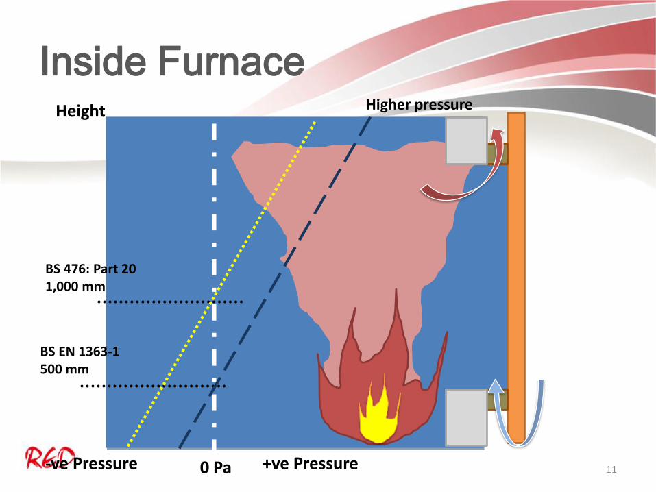
Inside Furnace
+ve Pressure 0 Pa -ve Pressure
Height
BS 476: Part 20 1,000 mm
BS EN 1363-1 500 mm
Higher pressure
11

Performance Criteria
• Integrity performance – The ability of the specimen to prevent the passage of
flames and hot gases through it and to prevent the occurrence of flame on the unexposed side
• Insulation performance – The ability of a specimen to restrict the temperature
rise of the unexposed face to below specific level
• Loadbearing capacity – The ability of a specimen intended to bear external
loading to support its load, without exceeding specified criteria with respect to both the extent of, and rate of deflection
12
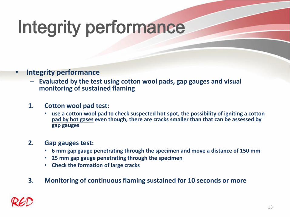
Integrity performance
• Integrity performance – Evaluated by the test using cotton wool pads, gap gauges and visual
monitoring of sustained flaming
1. Cotton wool pad test: • use a cotton wool pad to check suspected hot spot, the possibility of igniting a cotton
pad by hot gases even though, there are cracks smaller than that can be assessed by gap gauges
2. Gap gauges test:
• 6 mm gap gauge penetrating through the specimen and move a distance of 150 mm • 25 mm gap gauge penetrating through the specimen • Check the formation of large cracks
3. Monitoring of continuous flaming sustained for 10 seconds or more
13
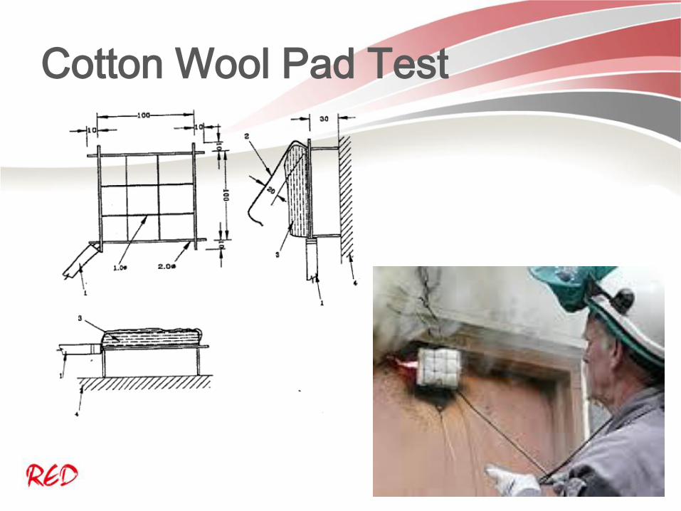
Cotton Wool Pad Test
14

Gap Gauges
15
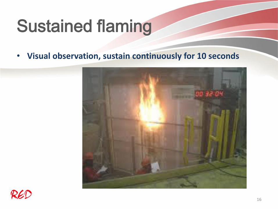
Sustained flaming
• Visual observation, sustain continuously for 10 seconds
16

What is Integrity?
• Prevent the fire or hot gases to penetrating through
• No matter how large or small scale of the flame is, as long as it sustained for 10 seconds, the integrity is regarded as fail
• Help to prevent fire spread, contain the fire within the compartment
17
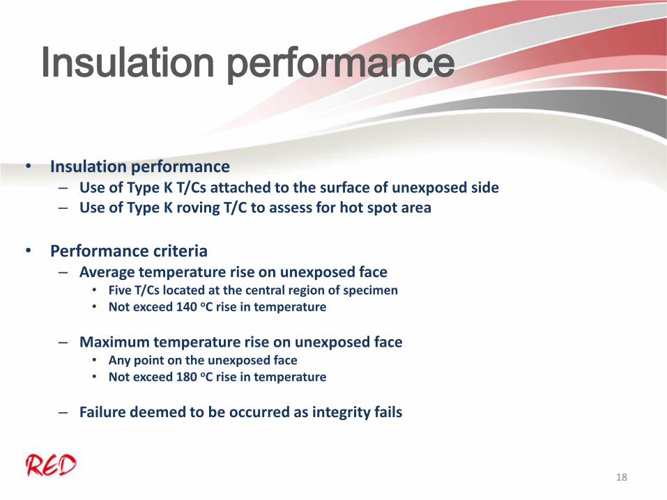
Insulation performance
• Insulation performance – Use of Type K T/Cs attached to the surface of unexposed side – Use of Type K roving T/C to assess for hot spot area
• Performance criteria
– Average temperature rise on unexposed face • Five T/Cs located at the central region of specimen • Not exceed 140 oC rise in temperature
– Maximum temperature rise on unexposed face • Any point on the unexposed face • Not exceed 180 oC rise in temperature
– Failure deemed to be occurred as integrity fails
18

Fire Test Standard: BS EN 1364-3
• BS EN 1364-3 – Full configuration of the curtain walling is tested
• Representative part or parts of the whole curtain walling
– Specimens with the sizes that can be accommodated by the furnace
depends on its opening, incorporated the fire rated glazing, horizontal sealing and vertical sealing
– Fixing details as in practice (spacing and the use of materials) or using weaker fixing (for follow up assessment purpose)
– Assess the separation function of the vertical and horizontal sealing to protect the adjacent surfaces not subjected to heat directly
19

Fire Test Standard: BS EN 1364-4
• BS EN 1364-4 – Test on partial configuration, may be the façade which have the
spandrel area fire rated but contains non-fire rated glazing outside the spandrel area
– Mainly test on part of the curtain walling system which is fire rated, e.g. spandrel (the upstand and/or downstand and the associated horizontal sealing and the fixing details)
20

Fire Test Standards
• Test on Partition to BS EN 1364-1 • Symmetrical System • Fixing at the top and bottom to the slab
within the concrete aperture • Nominal weight bear by the floor • Assess for
• Integrity • Insulation • may be load bearing capacity
• Test on Curtain Walling to BS EN 1364-3 • Asymmetrical System • Fixing at edge face of the slab • Fixing to bear the weight of the curtain wall • Assess for
• Integrity • Insulation • Perimeter sealing
21

Fire Test Standards
• Area above the spandrel affected by hot gas?
• Function of perimeter sealing (horizontal sealing)
• The ability of the fixing to bear the weight of thefaçade
• Function of vertical sealing. Area separated by walls and mullions can maintain compartmentation ?
• Boundary Condition
Min 500 mm
Min 150 mm
Min 500 mm
22

T/Cs locations on each surface and
sealings (Internal Exposure) View from unexposed side
View from exposed side
23

T/Cs locations on each surface and
sealings (External Exposure)
View from unexposed side
24

Observation during the test
• Observations below need to be recorded but not the performance criteria in the test: – Behaviours of fixings
• Failure of fixings • Sagging of the specimens occurred?
– Falling parts from the external face of the curtain walling
– Deflection of the curtain walling system
25

Deflection measurement
• Measurement of deflection is not compulsory in the test of non-loadbearing element
• Measurement will still be taken, as secondary evaluation of the integrity and insulation performance
• Large deflection lead to risk in integrity or insulation failure
• The deflection data is one of the key consideration for the follow up assessment after the test
26

Fire test: BS EN 1364-3
(External Exposure)
27

What’s the result represent? For Internal Exposure
Surface or Linear gap seal
Integrity
Insulation (for each discrete area ≥ 0.1 m2
Cotton pad
Gap gauge
Flaming Mean Temperature
Maximum Temperature
S2# 66 66 59 59* 59*
S3 66 - 66 66 66
S4 66 - 66 66 66
S5# 66 - 66 66 66
S6# 66 - 66 - 66
Horizontal Linear Gap Seal
66 66 66 - 66
Vertical Linear Gap Seal, if required
66 66 66 - 66
# Falling Parts, * Insulation deemed not to satisfy as the integrity failed
28

What’s the result represent? For External Exposure
Surface or Linear gap seal
Integrity
Insulation (for each discrete area ≥ 0.1 m2
Cotton pad
Gap gauge
Flaming Mean Temperature
Maximum Temperature
S1 67 67 67 67 67
S2# - - - - -
# Falling Parts
29

Design the specimen before test
• Critical to ‘design’ the test specimen in order to obtain the full and widest range of application, more than one test may be needed to test all the features
– Maximum mullions spacing, maximum gap width for sealing, the potential need for increasing the height span (the sizes of the sections for shorter span in test), etc.
• The sizes of the specimen is confined by the opening area of the test furnace (e.g.
normally 3m by 3m)
• The direct field of application allow maximum increase of 1.5 times of tested span of height (Section 13 of 2014 version referred) provided that
– With 10% performance overrun, deflection < 50 mm and adequate expansion coefficient allowed
> Tested 3m high span, maximum allowed is 4.5 m span in height
• For much longer span (>5 m), – The test using furnace with higher opening height (e.g. 4 m high furnace), and – Use of computer calculation, using larger sections to compensate for the required increased
moment due to increase in span – Additional measurement of temperature on the mullions or transoms
30

Latest version of BS EN 1364-3
and BS EN 1364-4
• The CoP Fire Safety nominates BS EN 1364-3: 2006 and BS EN 1364-4: 2007
• The test standards BS EN 1364-3 and BS EN 1364-4 had been updated in 2014
• In the 2014 version: – Incorporated the test method of curved (faceted) façade – More detail in the scope of direct field of application – Slight difference in the location of unexposed face
thermocouples for curtain wall containing fire rated glazing
31
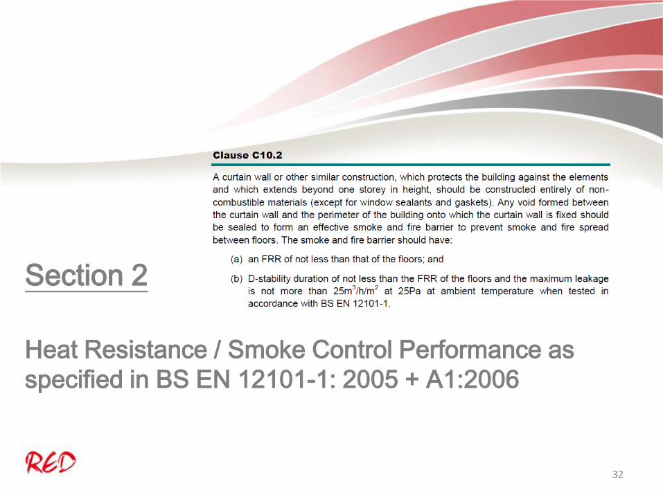
Section 2
Heat Resistance / Smoke Control Performance as
specified in BS EN 12101-1: 2005 + A1:2006
32

What is BS EN 12101-1: 2005 +
A1: 2006
• Smoke and heat control systems – Specification of smoke barriers – A specification, not a test standard – Describe how to test and which test method
shall refer to – Type of smoke barriers
• Static or active • Static barriers used at the void between façade
and floor slab
33

What is BS EN 12101-1: 2005 +
A1: 2006
• Annex D, Clause 5.2: Temperature/time Classification
• Test to vertical type of barrier (e.g automatic drop down smoke curtain)
• Using the general principle as in
BS EN 1363-1, 3m x 3 m specimen
• Only integrity is considered
34
What is BS EN 12101-1: 2005 +
A1: 2006
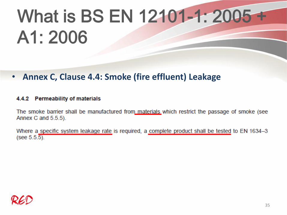
• Annex C, Clause 4.4: Smoke (fire effluent) Leakage
35

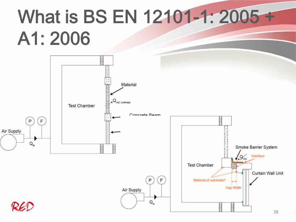
What is BS EN 12101-1: 2005 +
A1: 2006
• If checking the permeability of materials, then refer to Annex C
• Test method BS EN 1634-3, using a 1 m2 sample with edge tightly sealed
• Sample shall have typical seams and joints
• Pressure: 25 Pa, Temperature ambient or 200 oC
• Criteria: leakage rate is less than 25 m3/h/m2
36

What is BS EN 12101-1: 2005 +
A1: 2006
• Outcome: • The permeability of the
material is good for use as smoke barrier
• Limitation:
• May be irrelevant to the smoke leakage rate in the actual system
• Involve fixing details, interface between the substrate (aluminium mullion and concrete slab)
37
What is BS EN 12101-1: 2005 +
A1: 2006
38

What is BS EN 12101-1: 2005 +
A1: 2006
• If go for checking the leakage rate of a smoke barrier system
• Test method BS EN 1634-3, using representative portion with maximum 3m wide
• Sample shall have typical seams and joints as in practice
• Pressure: 25 Pa, Temperature: ambient or 200 oC
• Criteria: leakage rate is less than 25 m3/h/m2
39

What is BS EN 12101-1: 2005 +
A1: 2006
Vertical Section Horizontal Section
40

BS EN 1634-3 test
r in
Pressure developed
Air in = leakage out at constant pressure
Air out from supporting
Air out from supporting
Air out from barrier
Ai
41

BS EN 1634-3 test condition
42

BS EN 1634-3 test
Air in
Pressure developed
Air in = leakage out at constant pressure
Air out from supporting
Air out from supporting
Seal the barrier to measure the leakage rate from supporting Qapp+sup
43

BS EN 1634-3 test
Air in
Pressure developed
Air in = leakage out at constant pressure
Air out from supporting
Air out from supporting
Remove the seal to measure the leakage of all Qtotal
44

What is BS EN 1634-3
• The leakage rate of door will be Qtotal – Qapp+sup
• The measurement shall be done for each temperature condition at each
pressure point
• Measurement of Qtotal start after 30 minutes of heating period, and shall be done within 10 minutes
• The pressure shall be constant for 2 minutes and take the measurement
45
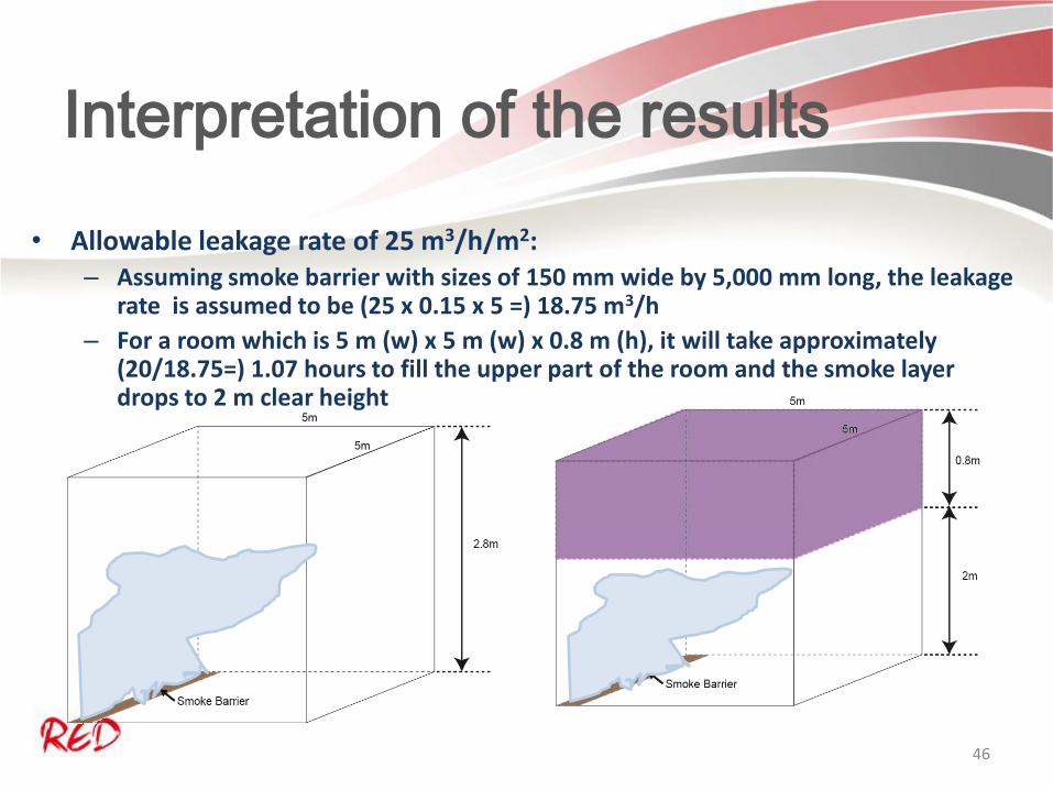
Interpretation of the results
• Allowable leakage rate of 25 m3/h/m2: – Assuming smoke barrier with sizes of 150 mm wide by 5,000 mm long, the leakage
rate is assumed to be (25 x 0.15 x 5 =) 18.75 m3/h
– For a room which is 5 m (w) x 5 m (w) x 0.8 m (h), it will take approximately (20/18.75=) 1.07 hours to fill the upper part of the room and the smoke layer drops to 2 m clear height
46

Fire Test?
Smoke Test?
• Fire Resistance Test and Smoke Control Test are two different tests
• The test are conducted separately with the use of different equipments
• Tests are conducted under different test conditions – Under fire test, the door subjected to over 1,000 oC and 20 Pa at the head of the
specimen – Under smoke test, the barrier subjected to ambient temperature or 200 oC and up to
50 Pa
• The barrier shall subject to the fire resistant test and smoke control test, separately, to prove that its design can satisfy the FRR and Smoke control performance
• The performance expression are different, 60 minutes FRR but no 60 minutes smoke control performance
47

Test for a system
• Both Fire Resistance Test and Smoke Control Test are test on a system but not a material
• The System include the installation, the assembly of different material
• The failure may due to a number of reason, even for the specimen tested, the result of fire test may be different every time.
48
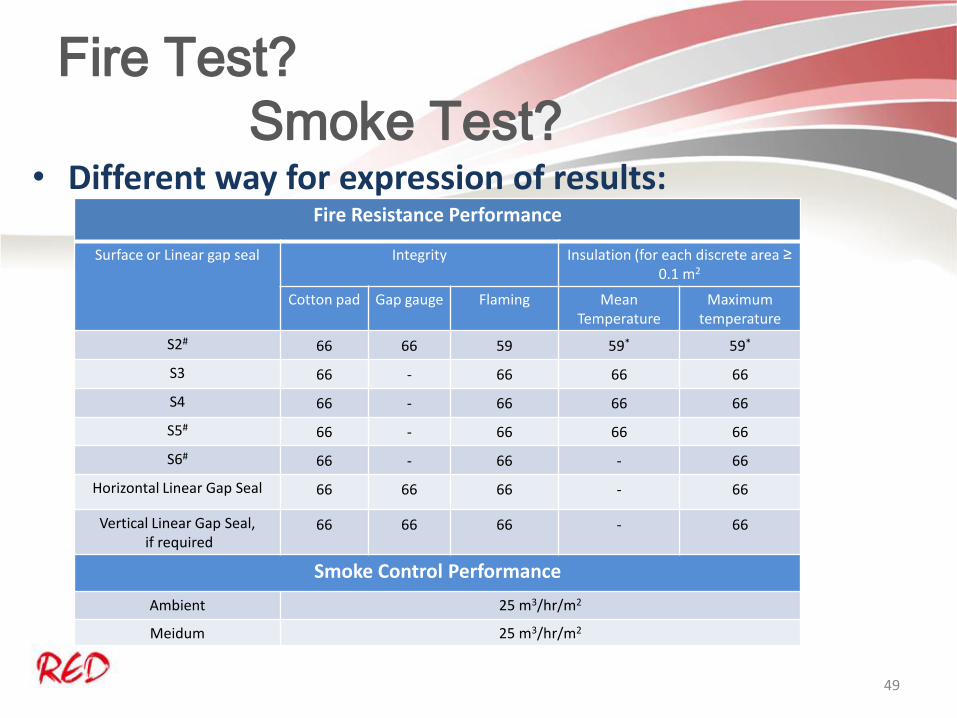
Fire Test?
Smoke Test? • Different way for expression of results:
Fire Resistance Performance
Surface or Linear gap seal Integrity
Insulation (for each discrete area ≥
0.1 m2
Cotton pad Gap gauge Flaming Mean Temperature
Maximum temperature
S2# 66 66 59 59* 59*
S3 66 - 66 66 66
S4 66 - 66 66 66
S5# 66 - 66 66 66
S6# 66 - 66 - 66
Horizontal Linear Gap Seal 66 66 66 - 66
Vertical Linear Gap Seal, if required
66 66 66 - 66
Smoke Control Performance
Ambient 25 m3/hr/m2
Meidum 25 m3/hr/m2
49

Section 3
Common issue on Tests for Curtain Walling Systems
50

Code of Practice for Fire Safety in
Buildings 2011
• Extract from CoP Fire Safety 2011
51

Fire Resistance Rating?
• Fire Resistance Period in old CoP
• Fire Resistance Rating in CoP 2011
• Definition in CoP 2011
52

What is the Fire Resistance Test
Standard?
• FRR of the barrier at the void?
• Which test standard shall refer to?
• Is the old BS 476: Part 20: 1987 applicable?
• How about if the façade is not fire rated
53

The Design to comply with Fire
Resistance Performance and Smoke
Control Performance
In case of fire, the barrier can’t resist fire and at the same time prevent the smoke pass through
54

Non-fire rated Façade
55

Q and A Section
Thank you for your attention
56

Q and A Section
Extract from BS EN 1364-3: 2014
57