Embed Size (px)
Citation preview
1
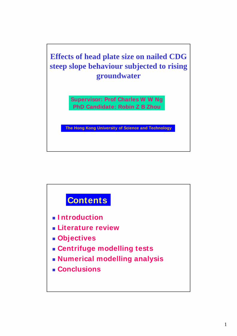
Effects of head plate size on nailed CDG steep slope behaviour subjected to rising
groundwater
Supervisor: Prof Charles W W NgPhD Candidate: Robin Z B Zhou
The Hong Kong University of Science and Technology
Contents
IntroductionLiterature reviewObjectivesCentrifuge modelling testsNumerical modelling analysisConclusions
2
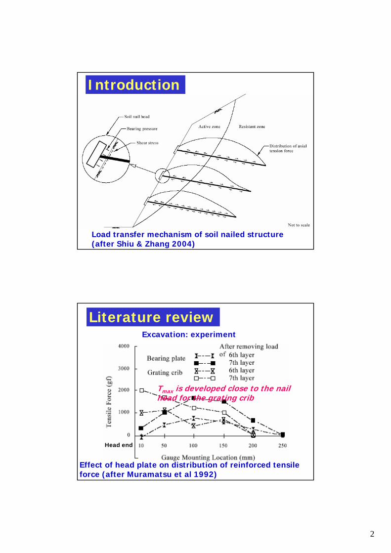
Introduction
Load transfer mechanism of soil nailed structure (after Shiu & Zhang 2004)
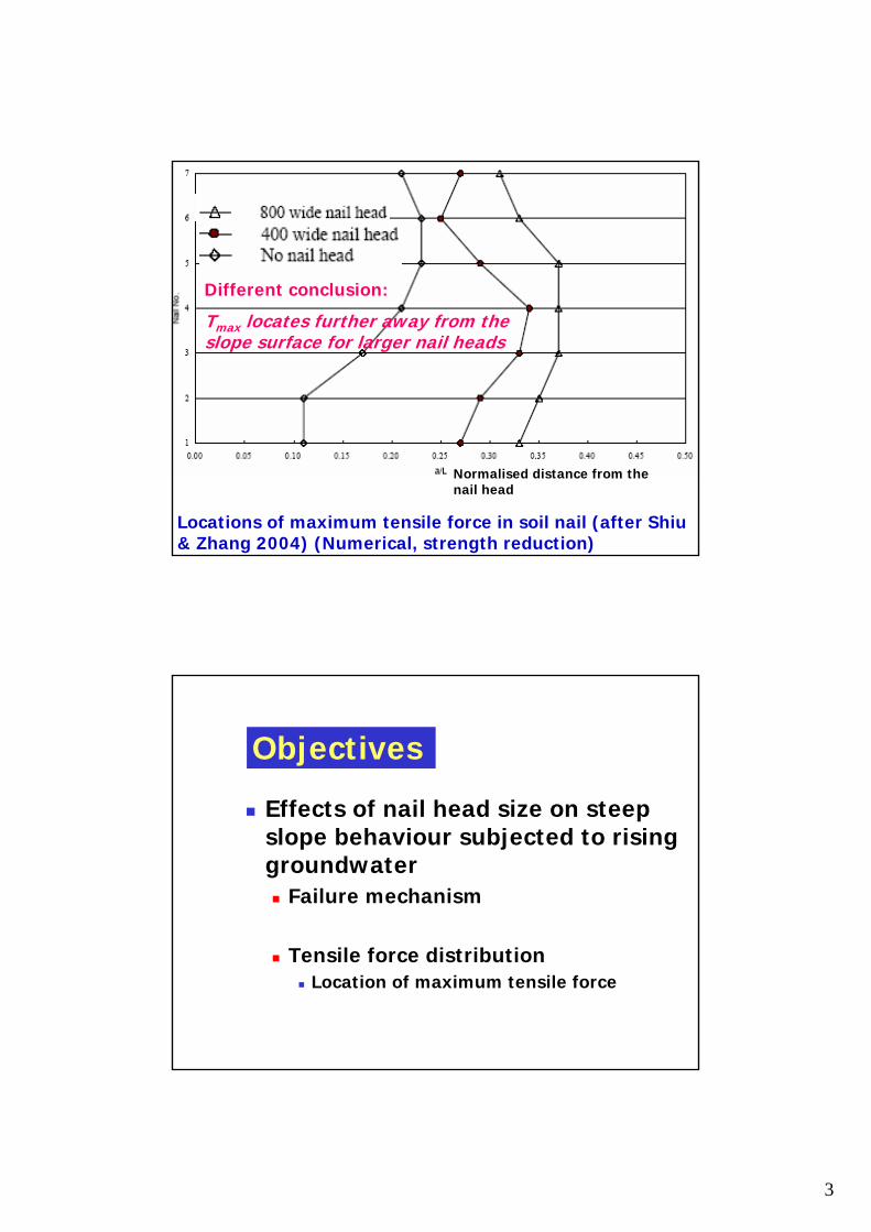
Literature review
Effect of head plate on distribution of reinforced tensile force (after Muramatsu et al 1992)
Tmax is developed close to the nail head for the grating crib
Excavation: experiment
Head end
3
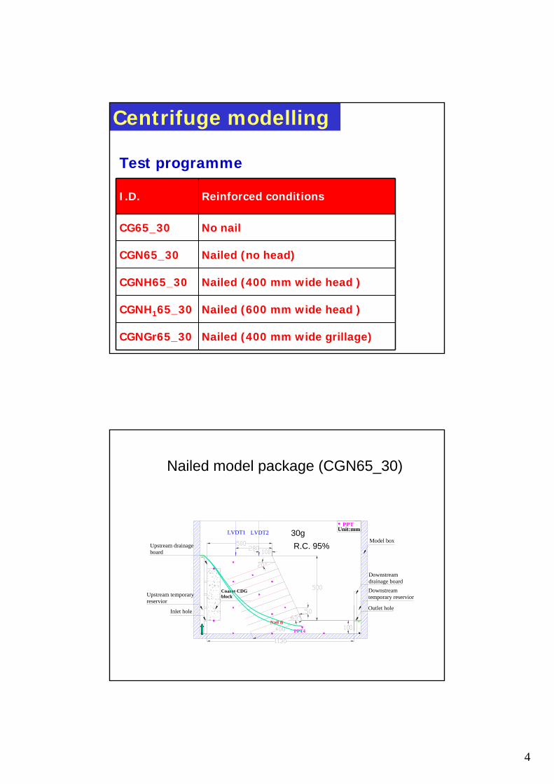
Locations of maximum tensile force in soil nail (after Shiu& Zhang 2004) (Numerical, strength reduction)
Normalised distance from the nail head
Different conclusion:
Tmax locates further away from the slope surface for larger nail heads
Objectives
Effects of nail head size on steep slope behaviour subjected to rising groundwater
Failure mechanism
Tensile force distributionLocation of maximum tensile force
4
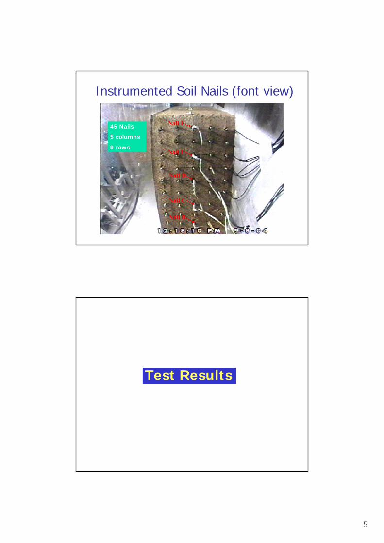
Centrifuge modelling
Nailed (400 mm wide grillage)CGNGr65_30
Nailed (600 mm wide head )
Nailed (400 mm wide head )
Nailed (no head)
No nail
Reinforced conditions
CGNH165_30
CGNH65_30
CG65_30
CGN65_30
I.D.
Test programme
Nailed model package (CGN65_30)
LVDT1PPT
Model box
Downstream drainage board
Upstream drainageboard
Outlet hole
Upstream temporary reservior
Downstream temporary reservior
Inlet hole
Unit:mm
Coarse CDG block
PPT4
LVDT2
Nail B
R.C. 95%30g
5
Instrumented Soil Nails (font view)
45 Nails
5 columns
9 rows
Test Results
6
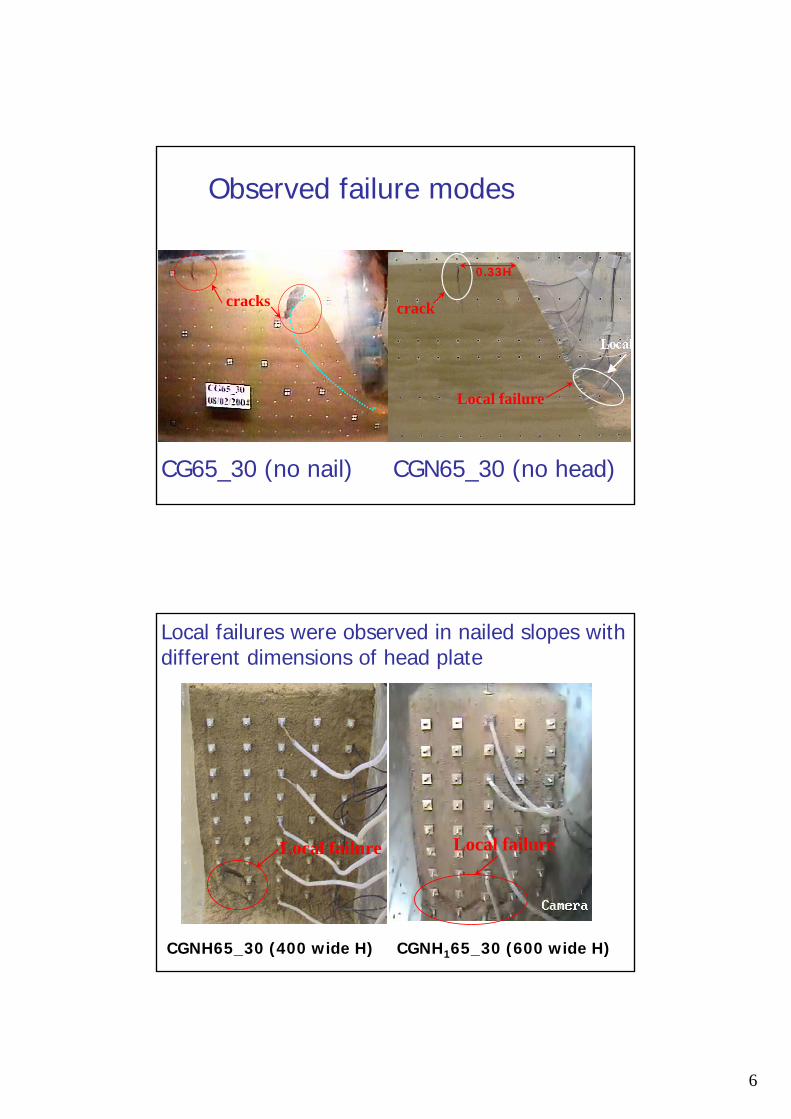
Observed failure modes
cracks
CGN65_30 (no head)
0.33H
crack
Local failure
CG65_30 (no nail)
Local failures were observed in nailed slopes with different dimensions of head plate
Localized failure
CGNH165_30 (600 wide H)CGNH65_30 (400 wide H)
Local failure Local failure
7
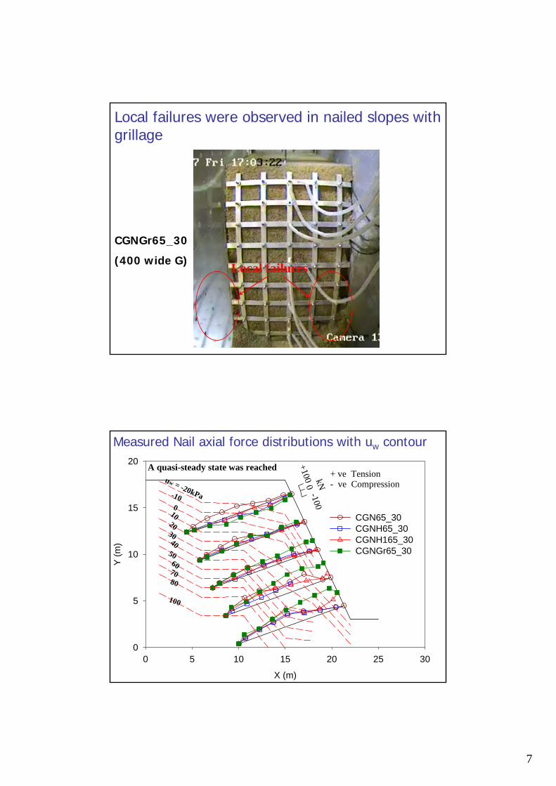
Local failures were observed in nailed slopes with grillage
Local failures
CGNGr65_30
(400 wide G)
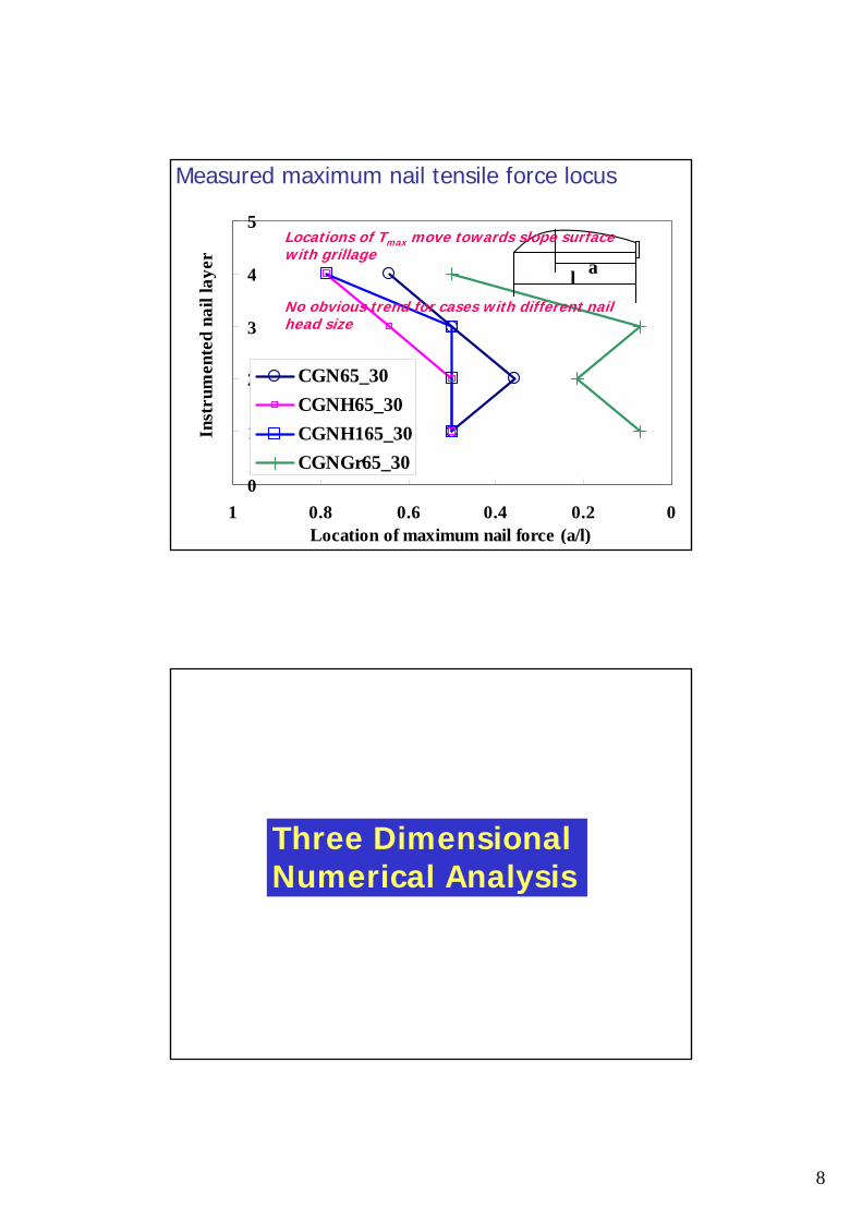
Measured Nail axial force distributions with uw contour
X (m)
0 5 10 15 20 25 30
Y (m
)
0
5
10
15
20
CGN65_30 CGNH65_30 CGNH165_30 CGNGr65_30
-100
0
+100 kN
A quasi-steady state was reached+ ve Tension- ve Compressionuw = -20kPa
100
60
100
8070
50
20
4030
-10
8
0
1
2
3
4
5
00.20.40.60.81Location of maximum nail force (a/l)
Inst
rum
ente
d na
il la
yer
CGN65_30CGNH65_30CGNH165_30CGNGr65_30
l a
Measured maximum nail tensile force locus
Locations of Tmax move towards slope surface with grillage
No obvious trend for cases with different nail head size
Three Dimensional Numerical Analysis
9
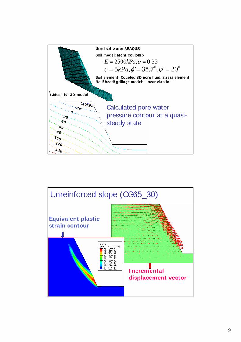
Used software: ABAQUS
Soil model: Mohr Coulomb
Mesh for 3D-model
35.0,2500 == υkPaE00 20,7.38',5' === ψφkPac
Soil element: Coupled 3D pore fluid/stress elementNail/head/grillage model: Linear elastic
-40kPa-200
2040
6080
100120140
Calculated pore water pressure contour at a quasi-steady state
Unreinforced slope (CG65_30)
Equivalent plastic strain contour
Incremental displacement vector
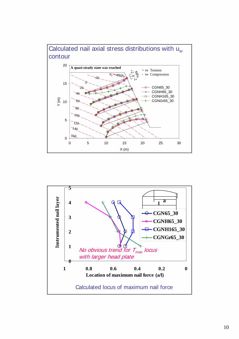
10
Calculated nail axial stress distributions with uwcontour
X (m)
0 5 10 15 20 25 30
Y (m
)
0
5
10
15
20
CGN65_30 CGNH65_30 CGNH165_30 CGNGr65_30
-2
0
+2 MPa
A quasi-steady state was reached+ ve Tension- ve Compressionuw=-40kPa-20
020
40
60
80
100
120140
160
Calculated locus of maximum nail force
0
1
2
3
4
5
00.20.40.60.81Location of maximum nail force (a/l)
Inst
rum
ente
d na
il la
yer
CGN65_30CGNH65_30CGNH165_30CGNGr65_30
l a
No obvious trend for Tmax locus with larger head plate
11
Summary (1)
For the slope without soil nail, a continuous slip surface was triggered by rising groundwaterInclusion of soil nails (without nail head) didprevent the formation of an obvious continuous slip surface but not crack at the crest and local failure near the toeFurther inclusion of nail heads is beneficial to prevent the failure with the active zone sliding off the upper soil
Summary (2)
Greater nail axial tensile forces (especially for lower nails) were mobilised close to slope surface with larger nail head plate/grillageUsed numerical model can simulate experimental nail force distribution reasonably if there is no crack was observed in the testFrom these models (experimental, numerical), Tmax locus does not lie further away from or closer to the head for larger nail heads
12
Thank You!
Q & A