Embed Size (px)
Citation preview
1
Senior Project:
Solar Bench
Submitted by:
Meshari Alharbi, Electrical Engineering
Sponsored by University of Evansville
Submitted to:
DR. Christina Howe
Project advisor:
Dr. Mohsen Lotfalian
Date and Place:
March 25, 2017
2
Acknowledgements:
I wish to express my gratitude to Dr. Lotfalian for advising my project, and Mr. Jeff Cron for his
help with acquiring parts support, guidance and encouragement, without which this project
wouldn’t have come forth. I would like also to express my gratitude to the staff of the Electrical
Engineering Department for their support during the project.
3
Table of Contents:
I. Introduction
II. Problem Definition
III. Design Approach
Main parts
IV. Safety and Environment
V. Standards
VI. Expected Result
VII. References
VIII. Appendix
4
Table of Figures:
Figure 1: PV system Demo
Figure 2: Arduino Nano layout
Figure 3: MP1584EN Buck converter
Figure 4: MP1584EN buck converter performance
Figure 5: Schematics for the charge controller
Figure 6: Final demo of the solar bench
Table of tables:
Table 1: Solar panels specification
Table 2: Charge controller specifications
Table 3: Charge controller parts coast
5
Solar Bench
I. Introduction:
In today’s technology, many products are being redesigned to be more efficient. As more
products become more portable, the demand for portable power increases. Due to the limitations
of fossil fuels, solar energy is becoming more popular as the renewable energy source that could
change the future. The world depended on oil and gas as the main sources of energy, which
damage the environment in many aspects. Some Engineers are trying to make energy without
effecting the environment (renewable energy), for example oxygen, fresh water, solar, timber,
and biomass energy. Solar energy has many benefits for individuals. For example, families can
reduce their electricity spending by using solar systems instead of using electrical companies
services. Also people can benefit from such methods in public places like public parks and
transportation stations etc.
On the other hand, countries and governments can benefit from solar energy. For instant
contrives can use clean energy to generate electricity for their people cheaper than generating
energy from oil and gasses, which means they can relay on such methods for economically
energy like solar energy aside with oil and gas. This project will result in a solar powered charger
that can provide energy out of the sunlight. The idea of the project is to have a DC current stored
in a battery from the solar panel that gets converted to AC current to charge small devises such
as phones and laptops. So, solar Cells receive sunlight and then generate DC current and send it
to charge controller to keep batteries from overcharging. Inverter converts the DC current to AC
current to the outlets.
6
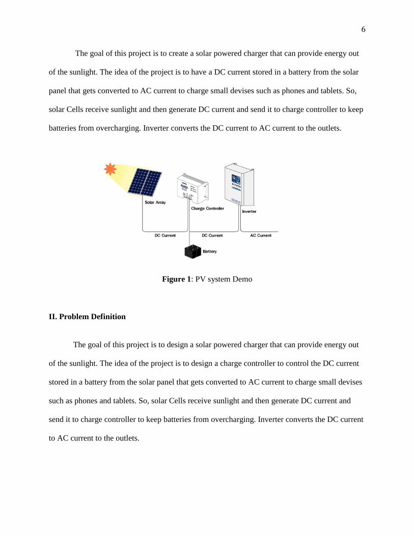
The goal of this project is to create a solar powered charger that can provide energy out
of the sunlight. The idea of the project is to have a DC current stored in a battery from the solar
panel that gets converted to AC current to charge small devises such as phones and tablets. So,
solar Cells receive sunlight and then generate DC current and send it to charge controller to keep
batteries from overcharging. Inverter converts the DC current to AC current to the outlets.
Figure 1: PV system Demo
II. Problem Definition
The goal of this project is to design a solar powered charger that can provide energy out
of the sunlight. The idea of the project is to design a charge controller to control the DC current
stored in a battery from the solar panel that gets converted to AC current to charge small devises
such as phones and tablets. So, solar Cells receive sunlight and then generate DC current and
send it to charge controller to keep batteries from overcharging. Inverter converts the DC current
to AC current to the outlets.
7
There are two methods for solar power production. The first one utilizes photovoltaic
(PV) cells to convert sunlight into an electric current, which is called photoelectric effect. A
photovoltaic cell takes advantage of this effect by harnessing the electron flow in the form of
direct current electricity. The second method of solar production is the concentrated solar power
(CSP) method. CSP generation uses mirrors to concentrate sunlight into a specific spot. Unlike
the PV method, the goal of the CSP method is to produce heat in order to drive a heat engine.
Electricity is produced via a generator connected to the heat engine. This project will be focusing
on the use of PV cells.
Due to the large amount of energy that we need to provide people with around the world,
we need to find more sources of energy. Solar charging can be a solution for many reasons I. Clean energy: Won’t affect the environment because it will not produce any kind of
pollution
II. Low coast: The coast for making a solar system power supply is cheap in the long
term compared with using electricity from the provided companies
III. Easy to work with: Solar power supply is easy to work with because it is safe and can
used by people easily.
IV. This type of method is already being used in public places like parks, schools and
some countries. For example in Japan they are making big solar systems (The
Yamakura Dam plant is due to begin operation by March 2018). This solar system is
divided into four main parts, which can give the consumer 300 watts a day.
8
III. Design Approach:
Solar systems in general are divided intro two main ways of connection. The first one is
grid-connected photovoltaic power system (on-grid) which the electricity generating solar PV
power system that is connected to the utility grid. And the other one is the Standalone
photovoltaic system (off-grid) is when your solar photovoltaic system is not connected to the
utility grid. For this project, the off-grid method was used, which means my system will not be
connected to the utility company. To make an off grid solar system we need to use 4 main parts.
Main part
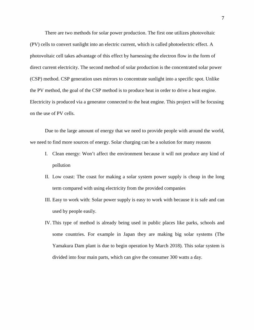
1) Solar Cells:
Solar cells are devices that convert light into energy. There are many types of solar panels; I am
using Monocrystalline solar panels for this project. Monocrystalline are slightly more
expensive, but also slightly more efficient. The mechanical engineering department has an extra
Monocrystalline 85 W panel was used for the project.
Table 1: Solar panels specification
Watts (STC), W 85W
Max Power (Vmp) 17.2 V
Max Current (Imp) 4.9 A
Weight (KG) 11.00 KG
Dimensions 1206 X 545 X 35mm

9
2) Battery bank:
I have used a 12 volt, 35Ah, last for 2 hours with 2 devices charging at the same time and able to
last for at least 30 minutes while supplying a 120 volt AC voltage. The outlet is which going
to charge the devises will take the power from the battery or the solar panels depends on the
logic situation. The output from the solar panel is dc power. Since the system will generate
electricity during specific time, we need to store this energy into the battery to keep charging all
the time.
First we calculate total Watt-hours per day used by appliances.
= 85W
Divide the total Watt-hours per day used by 0.85 for battery loss.
= 100W
Divide the power after loss by 0.6 for depth of discharge.
= 166W
Divide the answer obtained by the nominal battery voltage (using 12V)
= 13.9W
3) Power Inverter:
A solar inverter, or converter (PV inverter), converts direct current (DC) output of a
photovoltaic (PV) solar panel into a utility alternating current (AC) that can be fed into a
commercial electrical grid or used by a local, off-grid electrical system.
1- Converts DC to AC power
2- Offers one 110/120V AC outlet on a swivel
3- Built-in fault for circuit protection

10
Charge controller
For the hardware design, University of Evansville facilities and labs was used to test and
build the parts of the project. I’m going to use the 3D printers to make a box, which will contain
the charge controller and the inverter inside using AutoCAD Inventory. The charge controller is
a regulator that limits the amount of current added or drawn from the batteries. It also protects
the battery from overcharging and overvoltage, which can reduce battery performance or
lifespan, and may pose a safety risk. We cannot use normal voltage regulators because we need
to control current not voltages only.
Table 2: Charge controller parts
Charge controller Parts required
Arduino Nano
P-MOSFET IRF9549: act as switch
Power diode MBR2045: rectification
Buck converter
TVS diode P6KE36CA: It is used to protect sensitive components from electrical overstress
Transistors 2N3904
Resistors (100k x 2, 20k x 2,10k x 2,1k x 2, 330ohm x 5)
Ceramic Capacitors (0.1uF x 2)
Electrolytic Capacitors (100uF and 10uF)
11
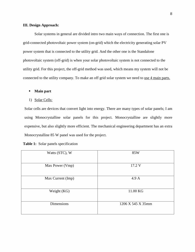
I. Arduino Nano: to make the current follow the logic to decide how to charge the load,
figure 2.
Figure 2: Arduino Nano layout
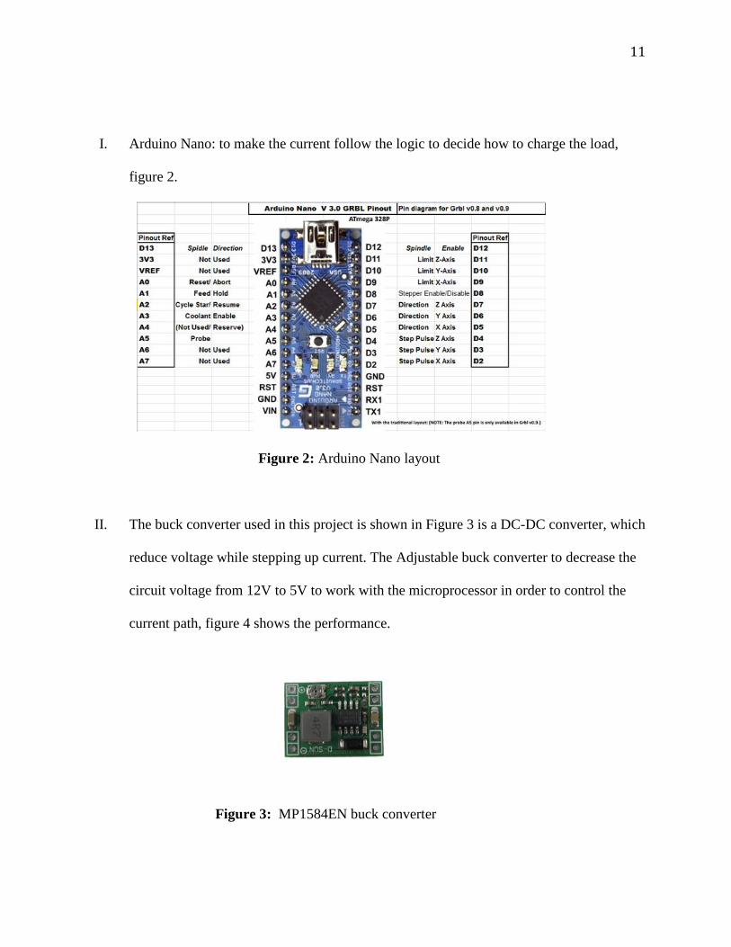
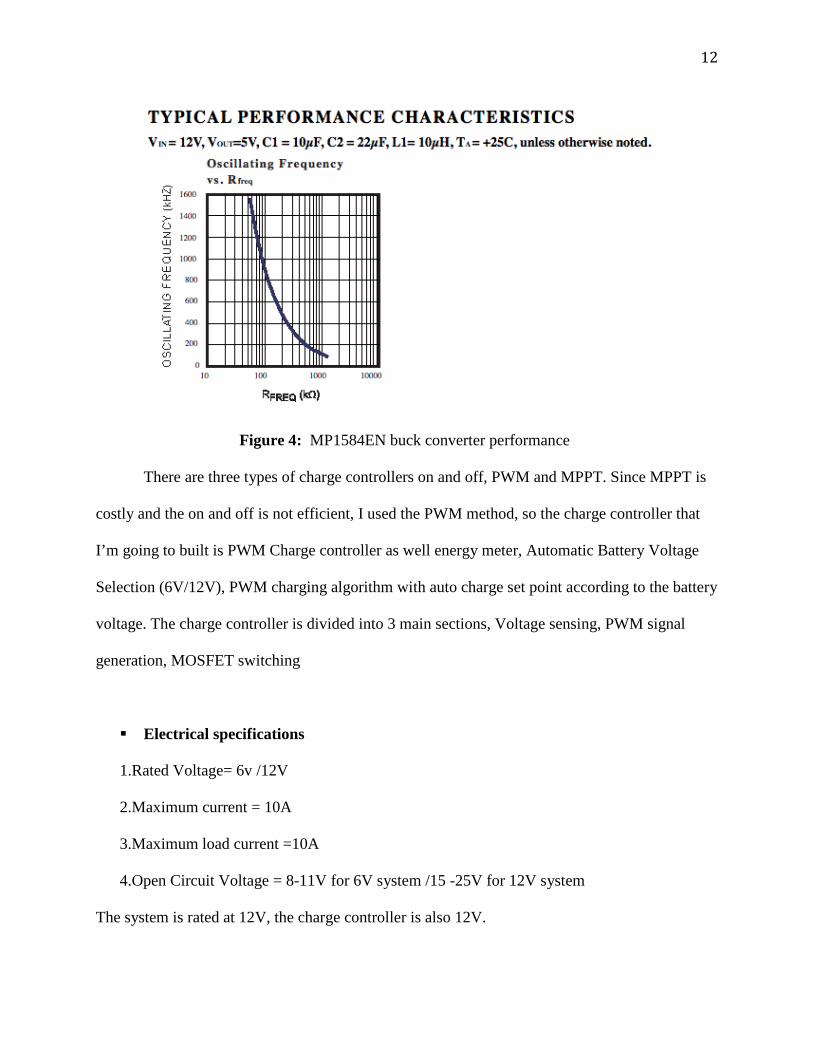
II. The buck converter used in this project is shown in Figure 3 is a DC-DC converter, which
reduce voltage while stepping up current. The Adjustable buck converter to decrease the
circuit voltage from 12V to 5V to work with the microprocessor in order to control the
current path, figure 4 shows the performance.
Figure 3: MP1584EN buck converter
12
Figure 4: MP1584EN buck converter performance
There are three types of charge controllers on and off, PWM and MPPT. Since MPPT is
costly and the on and off is not efficient, I used the PWM method, so the charge controller that
I’m going to built is PWM Charge controller as well energy meter, Automatic Battery Voltage
Selection (6V/12V), PWM charging algorithm with auto charge set point according to the battery
voltage. The charge controller is divided into 3 main sections, Voltage sensing, PWM signal
generation, MOSFET switching
Electrical specifications
1.Rated Voltage= 6v /12V
2.Maximum current = 10A
3.Maximum load current =10A
4.Open Circuit Voltage = 8-11V for 6V system /15 -25V for 12V system
The system is rated at 12V, the charge controller is also 12V.
13
Current rating = Power output of Panels / Voltage = 85 W / 12V = 7 Ah
So choose a Charge Controller of 12 V and more than 7 Ah.
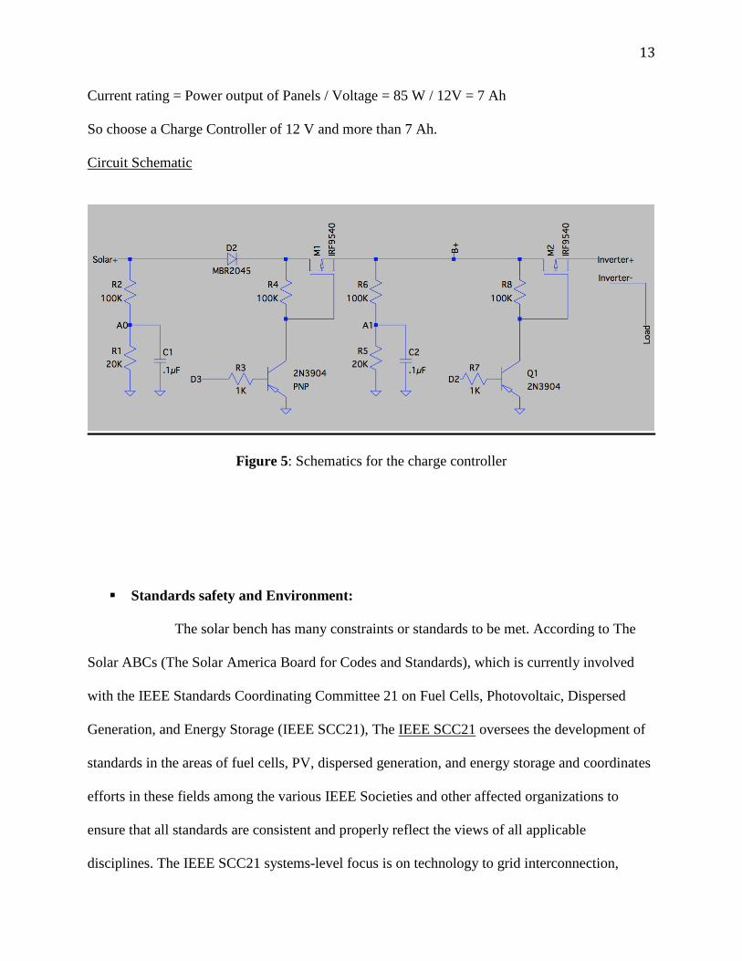
Circuit Schematic
Figure 5: Schematics for the charge controller
Standards safety and Environment:
The solar bench has many constraints or standards to be met. According to The
Solar ABCs (The Solar America Board for Codes and Standards), which is currently involved
with the IEEE Standards Coordinating Committee 21 on Fuel Cells, Photovoltaic, Dispersed
Generation, and Energy Storage (IEEE SCC21), The IEEE SCC21 oversees the development of
standards in the areas of fuel cells, PV, dispersed generation, and energy storage and coordinates
efforts in these fields among the various IEEE Societies and other affected organizations to
ensure that all standards are consistent and properly reflect the views of all applicable
disciplines. The IEEE SCC21 systems-level focus is on technology to grid interconnection,
14
integration and impacts, and, Smart Grid interoperability including electric-sourced
transportation and energy storage systems. (See appendix)
The use of solar energy is a sustainable solution to the energy challenges of today. Not
only do solar energy systems generate energy with zero greenhouse gas emissions, but the solar
industry has also taken on the responsibility to mitigate and manage the full range of social and
environmental impacts during the entire lifecycle of the solar energy system. These social and
environmental impacts include respecting the human rights of workers, ensuring the rights of
communities and other stakeholders are respected, and making business operations safe and
environmentally responsible. The use of solar energy is a sustainable solution to the energy
challenges today. The solar energy systems generate energy with zero greenhouse gas emissions.
The solar bench project has taken on the responsibility to manage following the standards of the
solar system. Also social and environmental impacts include respecting my classmates in the lab,
make sure that I don’t damage the solar panels since I borrow it from the mechanical engineering
department.
Solar energy is one of the cleanest was to generate energy and considered as a green
source of energy. Solar energy benefit ranges from low carbon emission, no fossil fuel
requirement, long-term solar resources, less payback time. However like other power generation
sources, solar energy has also some Safety, Health and Environmental (SHE) concerns. During
the process of making the solar bench, all the safety standers were followed and cables were
taped properly because an inverter was used which means AC current is involved in the circuit.
Manufacturability wise, many startups around the world is doing solar projects due.
15
Costs:
The University of Evansville has sponsored this project ($300). Most of the parts that are
used in this project were from the university of Evansville stockroom. The price for the solar
panel was $150 + shipping price witch was almost the same price as the solar panels itself. So, I
have used the solar panels provided by the Mechanical Engineering department. Dr. Mohsen
Lotfalian also provided me with the Inverter and the battery instead of buying them. The bench
was ordered from Target.com. The charge controller parts were either ordered online or was in
the university stockroom
Inverter: $150
Battery: $50
Solar arrays PV: $150
Bench: $47
Charge controller (UE stockroom)
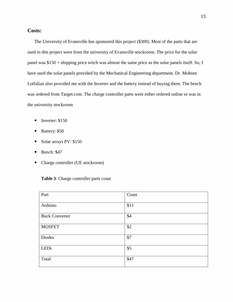
Table 3: Charge controller parts coast
Part Coast
Arduino $11
Buck Converter $4
MOSFET $2
Diodes $7
LEDs $5
Total $47
16
Conclusion:
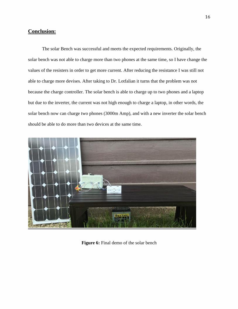
The solar Bench was successful and meets the expected requirements. Originally, the
solar bench was not able to charge more than two phones at the same time, so I have change the
values of the resisters in order to get more current. After reducing the resistance I was still not
able to charge more devises. After taking to Dr. Lotfalian it turns that the problem was not
because the charge controller. The solar bench is able to charge up to two phones and a laptop
but due to the inverter, the current was not high enough to charge a laptop, in other words, the
solar bench now can charge two phones (3000m Amp), and with a new inverter the solar bench
should be able to do more than two devices at the same time.
Figure 6: Final demo of the solar bench
17
References
[1] "Off-Grid Solar System Calculator." Off-Grid Solar System Calculator. N.p., n.d. Web.
02 Dec. 2016.. [online].
Available: http://www.easybib.com/cite/view
[2] @WaldenLabs. "9 Steps to Build a DIY Off-Grid Solar PV System - Walden Labs."
Walden Labs. N.p., 23 June 2016. Web. 07 Dec. 2016.. [online]. Available:
http://waldenlabs.com/diy-off-grid-solar-system/
[3] "Off-grid Solar Calculator - Affordable Solar Distribution." Affordable Solar. N.p., n.d.
Web. 07 Dec. 2016..
Available: http://www.affordable-solar.com/solar-tools/off-grid-estimator/
[4] Deba168. "ARDUINO SOLAR CHARGE CONTROLLER ( Version 2.0)."
Instructables.com. N.p., 26 Oct. 2014. Web. 07 Dec. 2016.
/.latest_citation_text
Available: http://www.instructables.com/id/ARDUINO-SOLAR-CHARGE-CONTROLLER-
Version-20/?ALLSTEPS
Http://www.solarabcs.org/index.html. The Solar America Board for Codes and Standards, n.d.
Web. 21 Apr. 2017.
[5] "SolarPro Magazine." Understanding and Optimizing Battery Temperature Compensation
| SolarPro Magazine. N.p., n.d. Web. 07 Dec. 2016.
/.latest_citation_text
Available: http://solarprofessional.com/articles/design-installation/understanding-and-
optimizing-battery-temperature-compensation

18
Appendices A. Standards:
PV-specific and systems-level IEEE SCC21 standards include the following (the "P" designation
are standards projects that are currently being developed and the others are published):
. IEEE 1547 - Standard for Interconnecting Distributed Resources with Electric Power Systems
. IEEE 1547.1 - Standard for Conformance Tests Procedures for Equipment Interconnecting
Distributed Resources with Electric Power Systems
. IEEE 1547.2 - Application Guide for IEEE 1547 Standard for Interconnecting Distributed
Resources with Electric Power Systems
. IEEE 1547.3 - Guide For Monitoring, Information Exchange, and Control of Distributed
Resources Interconnected with Electric Power Systems
. IEEE 1547.4 - Guide for Design, Operation, and Integration of Distributed Resource Island
Systems with Electric Power Systems
. IEEE 1547.6 - Recommended Practice For Interconnecting Distributed Resources With
Electric Power Systems Distribution Secondary Networks
. IEEE P1547.7 - Draft Guide to Conducting Distribution Impact Studies for Distributed
Resource Interconnection
. IEEE P1547.8 - Recommended Practice for Establishing Methods and Procedures that Provide
Supplemental Support for Implementation Strategies for Expanded Use of IEEE Standard
1547
. IEEE 937 - IEEE Recommended Practice for Installation and Maintenance of Lead-Acid
Batteries for Photovoltaic Systems
. IEEE 1013 - IEEE Recommended Practice for Sizing Lead-Acid Batteries for Stand-Alone
19
Photovoltaic Systems
. IEEE 1361 - IEEE Guide for Selection, Charging, Test and Evaluation of Lead-Acid Batteries
Used in Stand-Alone Photovoltaic Systems
. IEEE 1526 - Recommended Practice for Testing the Performance of Stand Alone Photovoltaic
Systems
. IEEE 1561 - Guide for Optimizing the Performance and Life of Lead-Acid Batteries in
Remote Hybrid Power Systems
. IEEE 1562 - Guide for Array and Battery Sizing in Stand-Alone Photovoltaic Systems
. IEEE 1661 - Guide for Test and Evaluation of Lead-Acid Batteries Used in Photovoltaic (PV)
Hybrid Power Systems
. IEEE 2030 - Guide for Smart Grid Interoperability of Energy Technology and Information
Technology Operation with the Electric Power System (EPS), and End-Use Applications
and Loads
. IEEE P2030.1 - Draft Guide for Electric-Sourced Transportation Infrastructure
. IEEE P2030.2 -Draft Guide for the Interoperability of Energy Storage Systems Integrated with
the Electric Power Infrastructure
IEEE P2030.3 - Draft Standard for Test Procedures for Electric Energy Storage Equipment and
Systems for Electric Power Systems Applications.
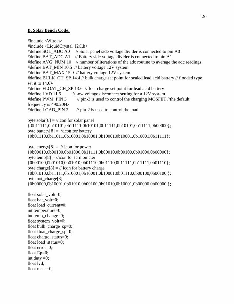
20
B. Solar Bench Code: #include <Wire.h> #include <LiquidCrystal_I2C.h> #define SOL_ADC A0 // Solar panel side voltage divider is connected to pin A0 #define BAT_ADC A1 // Battery side voltage divider is connected to pin A1 #define AVG_NUM 10 // number of iterations of the adc routine to average the adc readings #define BAT_MIN 10.5 // battery voltage 12V system #define BAT_MAX 15.0 // battery voltage 12V system #define BULK_CH_SP 14.4 // bulk charge set point for sealed lead acid battery // flooded type set it to 14.6V #define FLOAT_CH_SP 13.6 //float charge set point for lead acid battery #define LVD 11.5 //Low voltage disconnect setting for a 12V system #define PWM_PIN 3 // pin-3 is used to control the charging MOSFET //the default frequency is 490.20Hz #define LOAD_PIN 2 // pin-2 is used to control the load byte solar[8] = //icon for solar panel { 0b11111,0b10101,0b11111,0b10101,0b11111,0b10101,0b11111,0b00000}; byte battery[8] = //icon for battery {0b01110,0b11011,0b10001,0b10001,0b10001,0b10001,0b10001,0b11111}; byte energy[8] = // icon for power {0b00010,0b00100,0b01000,0b11111,0b00010,0b00100,0b01000,0b00000}; byte temp[8] = //icon for termometer {0b00100,0b01010,0b01010,0b01110,0b01110,0b11111,0b11111,0b01110}; byte charge[8] = // icon for battery charge {0b01010,0b11111,0b10001,0b10001,0b10001,0b01110,0b00100,0b00100,}; byte not_charge[8]= {0b00000,0b10001,0b01010,0b00100,0b01010,0b10001,0b00000,0b00000,}; float solar_volt=0; float bat_volt=0; float load_current=0; int temperature=0; int temp_change=0; float system_volt=0; float bulk_charge_sp=0; float float_charge_sp=0; float charge_status=0; float load_status=0; float error=0; float Ep=0; int duty =0; float lvd; float msec=0;
21
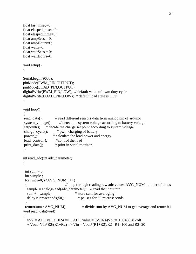
float last_msec=0; float elasped_msec=0; float elasped_time=0; float ampSecs = 0; float ampHours=0; float watts=0; float wattSecs = 0; float wattHours=0; void setup() { Serial.begin(9600); pinMode(PWM_PIN,OUTPUT); pinMode(LOAD_PIN,OUTPUT); digitalWrite(PWM_PIN,LOW); // default value of pwm duty cycle digitalWrite(LOAD_PIN,LOW); // default load state is OFF } void loop() { read_data(); // read different sensors data from analog pin of arduino system_voltage(); // detect the system voltage according to battery voltage setpoint(); // decide the charge set point according to system voltage charge_cycle(); // pwm charging of battery power(); // calculate the load power and energy load_control(); //control the load print_data(); // print in serial monitor } int read_adc(int adc_parameter) { int sum = 0; int sample ; for (int i=0; i<AVG_NUM; i++) { // loop through reading raw adc values AVG_NUM number of times sample = analogRead(adc_parameter); // read the input pin sum += sample; // store sum for averaging delayMicroseconds(50); // pauses for 50 microseconds } return(sum / AVG_NUM); // divide sum by AVG_NUM to get average and return it} void read_data(void) { //5V = ADC value 1024 => 1 ADC value = (5/1024)Volt= 0.0048828Volt // Vout=Vin*R2/(R1+R2) => Vin = Vout*(R1+R2)/R2 R1=100 and R2=20
22
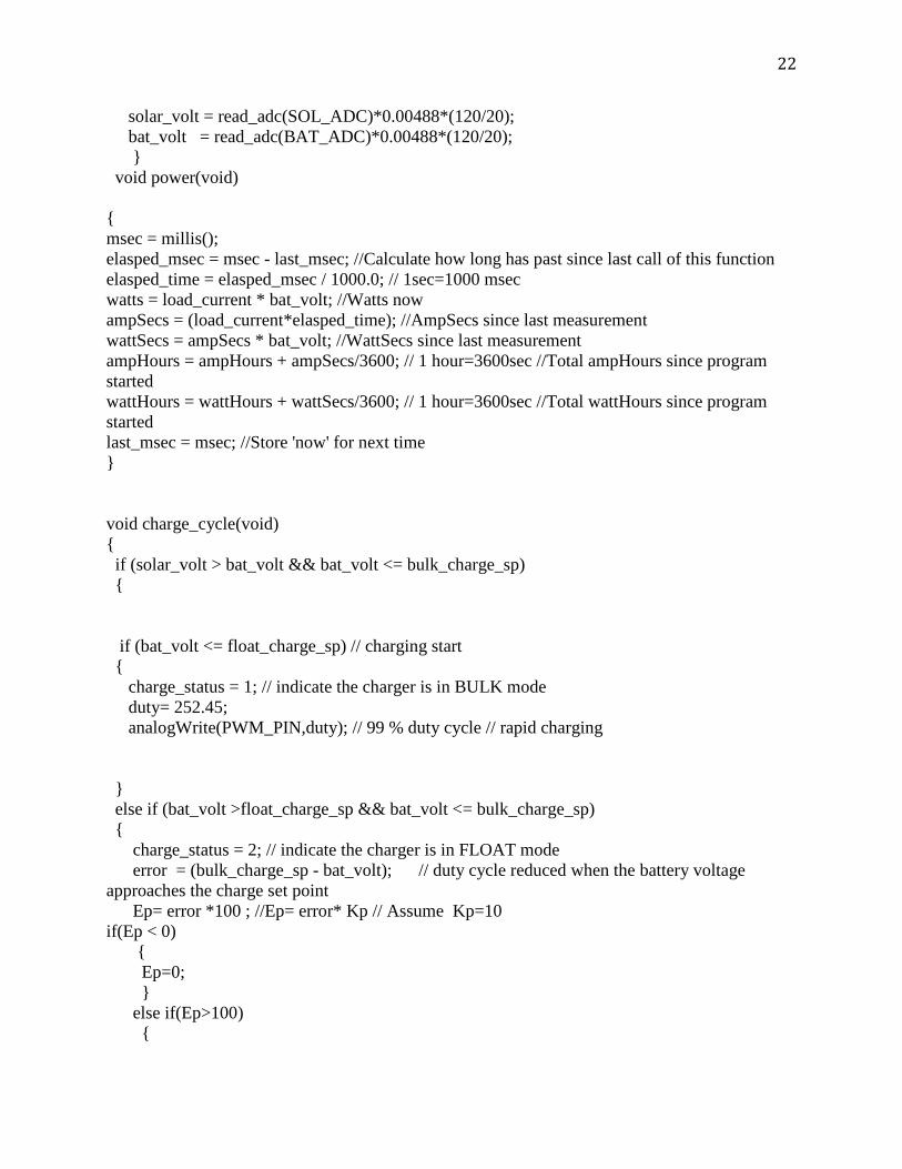
solar_volt = read_adc(SOL_ADC)*0.00488*(120/20); bat_volt = read_adc(BAT_ADC)*0.00488*(120/20); } void power(void) { msec = millis(); elasped_msec = msec - last_msec; //Calculate how long has past since last call of this function elasped_time = elasped_msec / 1000.0; // 1sec=1000 msec watts = load_current * bat_volt; //Watts now ampSecs = (load_current*elasped_time); //AmpSecs since last measurement wattSecs = ampSecs * bat_volt; //WattSecs since last measurement ampHours = ampHours + ampSecs/3600; // 1 hour=3600sec //Total ampHours since program started wattHours = wattHours + wattSecs/3600; // 1 hour=3600sec //Total wattHours since program started last_msec = msec; //Store 'now' for next time } void charge_cycle(void) { if (solar_volt > bat_volt && bat_volt <= bulk_charge_sp) { if (bat_volt <= float_charge_sp) // charging start { charge_status = 1; // indicate the charger is in BULK mode duty= 252.45; analogWrite(PWM_PIN,duty); // 99 % duty cycle // rapid charging } else if (bat_volt >float_charge_sp && bat_volt <= bulk_charge_sp) { charge_status = 2; // indicate the charger is in FLOAT mode error = (bulk_charge_sp - bat_volt); // duty cycle reduced when the battery voltage approaches the charge set point Ep= error *100 ; //Ep= error* Kp // Assume Kp=10 if(Ep < 0) { Ep=0; } else if(Ep>100) {
23
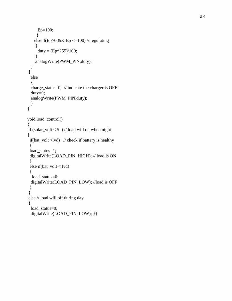
Ep=100; } else if(Ep>0 && Ep <=100) // regulating { duty = (Ep*255)/100; } analogWrite(PWM_PIN,duty); } } else { charge_status=0; // indicate the charger is OFF duty=0; analogWrite(PWM_PIN,duty); } } void load_control() { if (solar_volt < 5 ) // load will on when night { if(bat_volt >lvd) // check if battery is healthy { load_status=1; digitalWrite(LOAD_PIN, HIGH); // load is ON } else if(bat_volt < lvd) { load_status=0; digitalWrite(LOAD_PIN, LOW); //load is OFF } } else // load will off during day { load_status=0; digitalWrite(LOAD_PIN, LOW); }}