Embed Size (px)
Citation preview
6
Sensor Fusion Techniques in Navigation Application for Mobile Robot
Surachai Panich1 and Nitin Afzulpurkar2
1Srinakharinwirot University
2Asian Institute of Technology
Thailand
1. Introduction
Generally, the mobile robots are researched and used in many applications. The
fundamental method of navigation is localization, which includes aspects such as sensing,
mapping, localization, planning and control. In order to we build the navigation system for
mobile robot operating in unmodified environments, we must know the mobile robot’s
position in reference frame. Typically reference frame is a Cartesian or we can specify the
landmark as reference position. The dead reckoning based on odometry is widely to identify
and classify landmarks. Dead reckoning systems estimate the position of the mobile robot
with respect to an initial point by measuring linear and angular velocities or accelerations.
There are also hybrid models, which have sensor systems of both dead reckoning and
landmark recognition. Dead reckoning is the estimate of current position based on a
previously determined position or estimated speeds from a known past position over time.
This can also determine the future position by projecting an ordered course and speed of
advance from a known present position. A disadvantage of dead reckoning is that new
positions are calculated solely from previous positions. The errors of the process are
cumulative, so the error in the position fix grows with time (Hans-Joachim von der Hardt &
Didier Wolf Rene Husson, 1996; Hye Ri Park et al., 2009). Odometry is widely used in
mobile robots to estimate their position relative to reference frame. This method estimates
the position over time with errors accumulation due to the integration of velocity
measurements (Cristina Tar in Sauer and Hermann Brugger, 2001; Houshangi, N. and Azizi,
F., 2006; Agostino Martinelli, 2002). The navigation system for mobile robot based on
odometry has typically problem with inaccuracy. Because of the odometry problems
navigation systems for mobile robot application cannot work solely on dead reckoning. This
is the reason that the navigation system needs the addition of sensory information.
Additional sensors can be defined as information provided to assist the accomplishment of a
task by a system. Practically, sensor fusion refers to the integration process where the
different sources of sensory information are combined into one representational format.
Typically in navigation systems sensory information can be fused from complementary
sensors, redundant sensors or even from a single sensor over a period of time. The
advantage of sensory fusion provides uncertainty and noise reduction, failure toleration and
extended flexibility of sensor ability.
www.intechopen.com
Sensor Fusion - Foundation and Applications
102
2. Sensor system in navigation application
The navigation system plays very an important role and challenging competence for mobile
robot. In navigation application, a mobile robot must interpret its sensors data to extract
environment information, with which the mobile robot can determine its position. After
mobile robot can localize its position, it must decide how to act to achieve its purpose.
Lastly, the mobile robot must control its drive system to achieve the desired path. The
localization of mobile robot’s position has significant research,so in this chapter we
introduce mainly the navigation system for the successful localization with relative and
absolute instruments only. The increment distance of the robot‘s movement sensed with
wheel encoders is integrated to calculate position. Because measurement errors from
encoders are integrated, the position error is accumulated over time. Using additional
sensors can help to reduce the cumulative errors. There are many error sources of
differential encoder system from environmental factors, such as misalignment of the wheels,
uncertainty of wheel diameter, variation in the contact point between wheel and floor and
slipping.
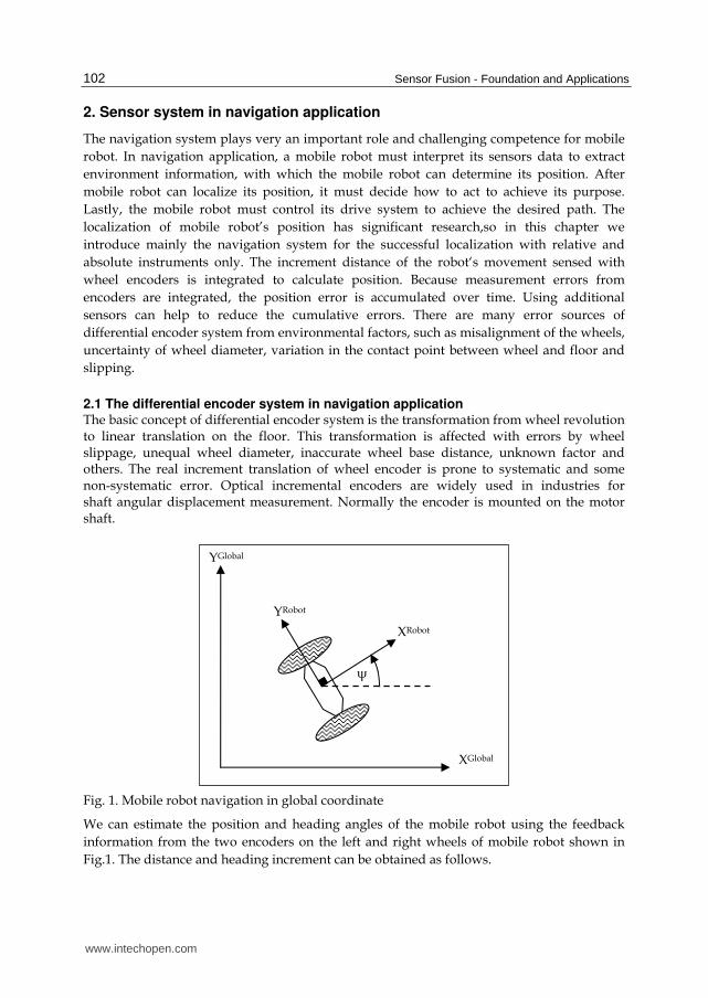
2.1 The differential encoder system in navigation application The basic concept of differential encoder system is the transformation from wheel revolution to linear translation on the floor. This transformation is affected with errors by wheel slippage, unequal wheel diameter, inaccurate wheel base distance, unknown factor and others. The real increment translation of wheel encoder is prone to systematic and some non-systematic error. Optical incremental encoders are widely used in industries for shaft angular displacement measurement. Normally the encoder is mounted on the motor shaft.
Fig. 1. Mobile robot navigation in global coordinate
We can estimate the position and heading angles of the mobile robot using the feedback
information from the two encoders on the left and right wheels of mobile robot shown in
Fig.1. The distance and heading increment can be obtained as follows.
XGlobal
ψ
XRobot
YRobot
YGlobal
www.intechopen.com
Sensor Fusion Techniques in Navigation Application for Mobile Robot
103
Δd +ΔdΔd =
2
encoder encoderR,k L,kencoder
k
(1)
Δd - Δd
Δψ =B
encoder encoderR,k L,kencoder
kk
(2)
Then the position can be estimated as
1 ,X = X +Δdencoderk k x k+ (3)
1 ,Y = Y +Δdencoderk k y k+ (4)
1ψ = ψ +Δψencoderk k k+ (5)
where
,Δd = Δd cosψencoder encoderx k k k∗
,Δd = Δd sinψencoder encodery k k k∗
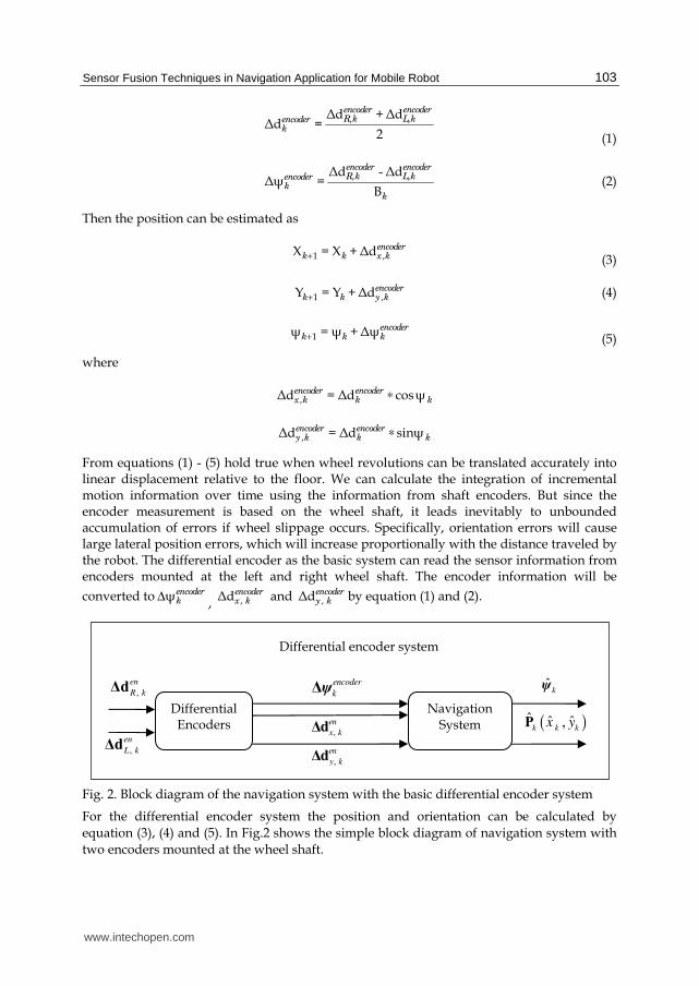
From equations (1) - (5) hold true when wheel revolutions can be translated accurately into linear displacement relative to the floor. We can calculate the integration of incremental motion information over time using the information from shaft encoders. But since the encoder measurement is based on the wheel shaft, it leads inevitably to unbounded accumulation of errors if wheel slippage occurs. Specifically, orientation errors will cause large lateral position errors, which will increase proportionally with the distance traveled by the robot. The differential encoder as the basic system can read the sensor information from encoders mounted at the left and right wheel shaft. The encoder information will be
converted to ψencoderkΔ
, , Δdencoderx k and , Δdencoder
y k by equation (1) and (2).
Fig. 2. Block diagram of the navigation system with the basic differential encoder system
For the differential encoder system the position and orientation can be calculated by
equation (3), (4) and (5). In Fig.2 shows the simple block diagram of navigation system with
two encoders mounted at the wheel shaft.
,
en
L kΔd
,
en
R kΔd
Differential Encoders
,
en
x kΔd
,
en
y kΔd
Navigation System ( )ˆ ˆ ˆ,
k k kx yP
ˆkψ ψencoder
kΔ
Differential encoder system
www.intechopen.com
Sensor Fusion - Foundation and Applications
104
2.2 Complementary sensors for differential encoder system Although the differential encoder system for mobile robot is practice in navigation application, the mobile robot’s position is estimated over time with unbound errors accumulation due to the integration of sensor information. To construct a reliable navigation system, sensor fusion is considered to improve the position estimation generated by differential encoder system. Many researchers worked on sensor fusion with variety of sensors.
2.2.1 Gyroscope Gyros measure rotational rate, which can be integrated to yield orientation. Typically, Gyroscope is mounted at the mobile robot. Many researchers work on fusion between encoder and gyroscope (Komoriya, K. and Oyama, E., 1994; Houshangi, N. and Azizi, F., 2006)
2.2.2 Compass Compass is a navigational instrument for determining direction relative to the Earth's magnetic poles. It can be used to calculate heading and provided a much improved navigational capability. A compass is any magnetically sensitive device capable of indicating the direction of the magnetic north of a planet's magnetosphere. In navigation compass is introduced to capture the navigating direction information including direction angle and angular velocity (Yikang Yang, 2002).
2.2.3 Ultrasonic sensor Ultrasonic sensor generates an ultrasonic pulse in a particular direction. If there is an object in the range of this pulse, part or all of the pulse will be reflected back to the transmitter as an echo and can be detected through the receiver. By measurement of the difference in time between the transmitted pulse and the received echo, it is possible to determine object’s range. In navigation system, ultrasonic sensors play an important role for automatic guidance (Miao Yu and Li Shu-qin, 2010; Tao Guo and Silamu, W., 2009).
2.2.4 Camera Camera is used to determine the relationship between the three-dimensional geometric location of one point and its corresponding point in the image. In many applications for navigation system, camera is utilized to detect landmarks and match them to pre-provided map information for localization. They implement matching process using environmental objects such as walls or obstacles. (Zhang, J., et. al, 2010; Chen, Yen-Sheng, et. al, 2010)
2.2.5 Accelerometer Accelerometer measures static acceleration forces such as gravity, allowing it to be used as a
tilt sensor (Surachai, P., 2009).
2.2.6 Light intensity sensor Light intensity sensor system measures light in analog and convert to digital values. In a Cartesian coordinate system the robot’s current position can be determined using the differences between opposite light intensity sensors in X and Y direction due to reference frame (Surachai, P., 2009).
www.intechopen.com
Sensor Fusion Techniques in Navigation Application for Mobile Robot
105
3. Sensor fusion algorithm
Consider an algorithm to comprise of two sensors, which are sensor A and B. The data processing algorithm, which can combine the information from sensor A and B generates the proper estimate. The measurements of sensor A and B are given as
, δA k Ax= +Z (6)
, δB k Bx= +Z (7)
where x is true value and δ is measurement error.
The estimate of x is determined using the combination of information from sensor A and B
and defined as
, , , ,X w Z w Zk A k A k B k B k= ∗ + ∗ (8)
where ,wA k and ,wB k are optimal quantity computed by variances.
To fuse information of two sensors corrupted by error, the optimal estimation (Gelb, 1974) can be expressed as follows
2 2
, ,, ,2 2 2 2
, , , ,
σ σX = * Z + * Z
σ +σ σ +σB k A k
k A k B k
A k B k A k B k
(9)
where ,A kZ is the measurement from sensor A with error variance ( 2,σA k ) and ,ZB k is the
measurement from sensor B with error variance ( 2,σB k ).
Generally, the differential encoder system generates incremental distance and heading and with integration of them over time the position and orientation are estimated. In this work the differential encoder is used as basic system in navigation purpose for mobile robot. To improve the accuracy of basic drive system the complementary systems with additional sensors are combined by sensor fusion algorithm. The complementary system can give the information both increment position and orientation and also both absolute position and orientation. This complementary information will be combined with information generated by differential encoder system with fusion algorithm.
3.1 Sensor fusion between differential encoder as basic system of mobile robot and gyroscope as relative complementary system with incremental rotation The creation of relative complementary for differential encoder sytem is the compensation of incremental translation and rotation. With the compensation of additional relative sensor, it can reduce error directly generated by encoders. Gyroscope is widely used to compensate error in many applications. Many researchers on robotic field work on about gyroscope sensor (Komoriya & Oyama, 1994; Karthick Srinivasan and Jason Gu, 2007). The dominant gyroscope random errors are the random bias and the scale factor error. Generally, the gyroscope output signal is not zero even though there is no input and the effect of the earth rotation is neglected. The bias error of gyroscope is the signal output from the gyroscope when it is not any rotation. The bias error tends to vary with temperature and over time. The scale factor relates the output of the gyroscope to rotation angle of corresponding gyroscope about its
www.intechopen.com
Sensor Fusion - Foundation and Applications
106
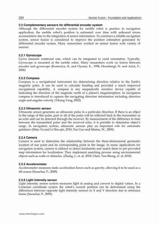
input axis. By error of the scale factor in gyroscope it means the deviation between the actual scale factor and the nominal scale factor. The output beat frequency changes with the changing of the scale factor when the input rate is the same, which affects precision of gyro directly. This chapter introduces relative complementary system of incremental rotation
Δ Gkψ with gyroscope sensor. The output of gyroscope is used to compensate the rotation
increment. The commercial gyroscope CRS-03 is selected working in measurement area ±
200°/s and Δ Gkψ = 3.2°±0.01° as shown in Fig.3. It is used to combine with differential
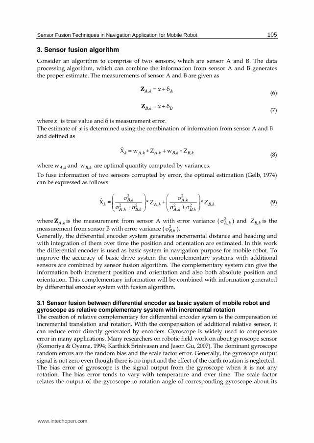
encoder system for error reduction of incremental rotation as shown in Fig.4.
Fig. 3. Gyroscope CRS03
Fig. 4. Block diagram of the navigation system with the basic differential encoder system compensated with gyroscope.
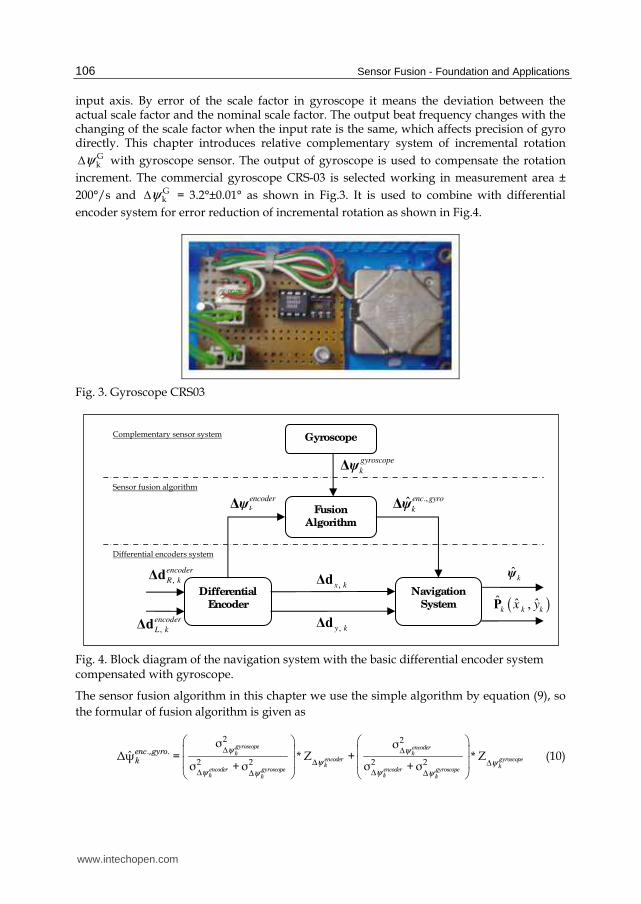
The sensor fusion algorithm in this chapter we use the simple algorithm by equation (9), so
the formular of fusion algorithm is given as
2 2
., .
2 2 2 2
σ σˆΔψ = * Z + * Z
σ +σ σ +σ
gyroscope encoderk k
encoder gyroscopek k
encoder gyroscope encoder gyroscopek kk k
enc gyrok
ψ ψ
ψ ψψ ψψ ψ
Δ Δ
Δ Δ
Δ ΔΔ Δ
(10)
Differential
Encoder
Fusion
Algorithm
, x kΔd
, y kΔd
Gyroscope
.,ψenc gyro
kΔ
Navigation
System ( )ˆ ˆ ˆ,k k kx yP
ˆkψ
ψencoder
kΔ
ψ gyroscope
kΔ
,
encoder
R kΔd
,
encoder
L kΔd
Differential encoders system
Sensor fusion algorithm
Complementary sensor system
www.intechopen.com
Sensor Fusion Techniques in Navigation Application for Mobile Robot
107
where ., .ˆΔψenc gyro
k is the estimated incremental rotation from sensor fusion algorithm,
ΔψZ encoderk
is the measurement of incremental rotation read from encoder,
ΔψZ gyroscopek
is the measurement of incremental rotation read from gyroscope,
2Δψσ encoder
k
is variance of the measurement of incremental rotation read from encoder and
2
Δψσ gyroscopek
is variance of the measurement of incremental rotation read from gyroscope.
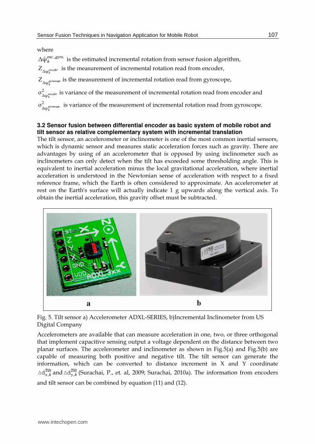
3.2 Sensor fusion between differential encoder as basic system of mobile robot and tilt sensor as relative complementary system with incremental translation The tilt sensor, an accelerometer or inclinometer is one of the most common inertial sensors, which is dynamic sensor and measures static acceleration forces such as gravity. There are advantages by using of an accelerometer that is opposed by using inclinometer such as inclinometers can only detect when the tilt has exceeded some thresholding angle. This is equivalent to inertial acceleration minus the local gravitational acceleration, where inertial acceleration is understood in the Newtonian sense of acceleration with respect to a fixed reference frame, which the Earth is often considered to approximate. An accelerometer at rest on the Earth's surface will actually indicate 1 g upwards along the vertical axis. To obtain the inertial acceleration, this gravity offset must be subtracted.
Fig. 5. Tilt sensor a) Accelerometer ADXL-SERIES, b)Incremental Inclinometer from US Digital Company
Accelerometers are available that can measure acceleration in one, two, or three orthogonal that implement capacitive sensing output a voltage dependent on the distance between two planar surfaces. The accelerometer and inclinometer as shown in Fig.5(a) and Fig.5(b) are capable of measuring both positive and negative tilt. The tilt sensor can generate the information, which can be converted to distance increment in X and Y coordinate
,Tiltx kΔd and ,
Tilty kΔd (Surachai, P., et. al, 2009; Surachai, 2010a). The information from encoders
and tilt sensor can be combined by equation (11) and (12).
www.intechopen.com
Sensor Fusion - Foundation and Applications
108
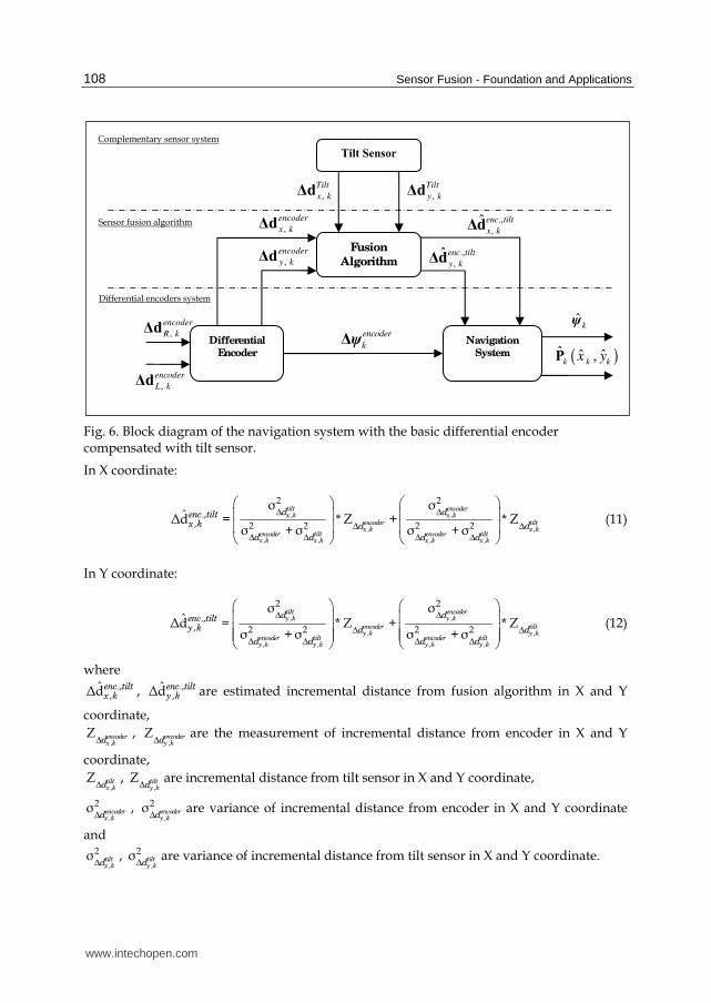
Fig. 6. Block diagram of the navigation system with the basic differential encoder compensated with tilt sensor.
In X coordinate:
, ,
, ,
, , , ,
2 2
.,, 2 2 2 2
σ σˆΔd = * Z + * Z
σ +σ σ +σ
tilt encoderx k x k
encoder tiltx k x k
encoder tilt encoder tiltx k x k x k x k
d denc tiltx k d d
d d d d
Δ Δ
Δ Δ
Δ Δ Δ Δ
(11)
In Y coordinate:
, ,
, ,
, , , ,
2 2
.,, 2 2 2 2
σ σˆΔd = * Z + * Z
σ +σ σ +σ
tilt encodery k y k
encoder tilty k y k
encoder tilt encoder tilty k y k y k y k
d denc tilty k d d
d d d d
Δ Δ
Δ Δ
Δ Δ Δ Δ
(12)
where .,
,ˆΔdenc tilt
x k , .,,
ˆΔdenc tilty k are estimated incremental distance from fusion algorithm in X and Y
coordinate,
,Z encoder
x kdΔ,
,Z encoder
y kdΔare the measurement of incremental distance from encoder in X and Y
coordinate,
,Z tilt
x kdΔ,
,Z tilt
y kdΔare incremental distance from tilt sensor in X and Y coordinate,
,
2σ encoderx kdΔ
, ,
2σ encodery kdΔ
are variance of incremental distance from encoder in X and Y coordinate
and
,
2σ tiltx kdΔ
, ,
2σ tilty kdΔ
are variance of incremental distance from tilt sensor in X and Y coordinate.
,
encoder
R kΔd
,
encoder
L kΔd
Differential
Encoder
Fusion
Algorithm
,
encoder
x kΔd
,
encoder
y kΔd
Tilt Sensor
Navigation
System
( )ˆ ˆ ˆ,
k k kx yP
ˆkψ
ψencoder
kΔ
,
Tilt
x kΔd
Differential encoders system
Sensor fusion algorithm
Complementary sensor system
,
Tilt
y kΔd
.,
, ˆ enc tilt
x kΔd
.,
, ˆ enc tilt
y kΔd
www.intechopen.com
Sensor Fusion Techniques in Navigation Application for Mobile Robot
109
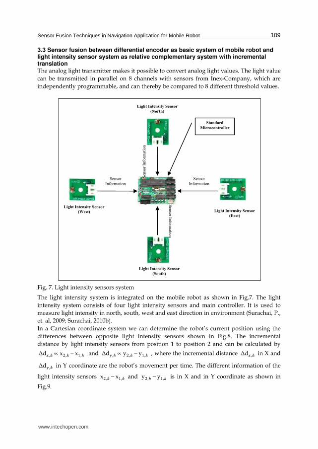
3.3 Sensor fusion between differential encoder as basic system of mobile robot and light intensity sensor system as relative complementary system with incremental translation The analog light transmitter makes it possible to convert analog light values. The light value
can be transmitted in parallel on 8 channels with sensors from Inex-Company, which are
independently programmable, and can thereby be compared to 8 different threshold values.
Fig. 7. Light intensity sensors system
The light intensity system is integrated on the mobile robot as shown in Fig.7. The light
intensity system consists of four light intensity sensors and main controller. It is used to
measure light intensity in north, south, west and east direction in environment (Surachai, P.,
et. al, 2009; Surachai, 2010b).
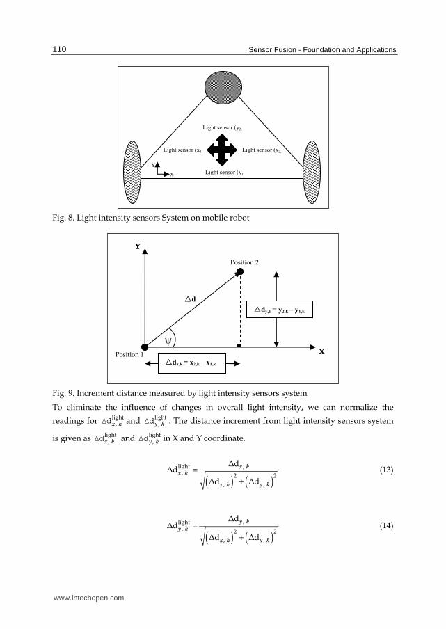
In a Cartesian coordinate system we can determine the robot’s current position using the
differences between opposite light intensity sensors shown in Fig.8. The incremental
distance by light intensity sensors from position 1 to position 2 and can be calculated by
, 2 , 1,Δd x xx k k k∝ − and , 2 , 1,Δd y yy k k k∝ − , where the incremental distance ,Δdx k
in X and
,Δdy k in Y coordinate are the robot’s movement per time. The different information of the
light intensity sensors 2, 1,x xk k− and 2, 1,y yk k− is in X and in Y coordinate as shown in
Fig.9.
Light Intensity Sensor
(West)
Light Intensity Sensor
(North)
Light Intensity Sensor
(South)
Light Intensity Sensor
(East)
Sensor
Information
Sensor
Information
Sen
sor
Info
rmat
ion
S
enso
r Info
rmatio
n
Standard
Microcontroller
www.intechopen.com
Sensor Fusion - Foundation and Applications
110
Fig. 8. Light intensity sensors System on mobile robot
Fig. 9. Increment distance measured by light intensity sensors system
To eliminate the influence of changes in overall light intensity, we can normalize the
readings for light, x kΔd and light
, y kΔd . The distance increment from light intensity sensors system
is given as light, x kΔd and light
, y kΔd in X and Y coordinate.
( ) ( )
light , , 2 2
, ,
ΔdΔd
Δd Δd
x kx k
x k y k
=
+
(13)
( ) ( )
, light, 2 2
, ,
ΔdΔd
Δd Δd
y k
y k
x k y k
=
+
(14)
Position 1
ψ
dx,k = x2,k – x1,k
dy,k = y2,k – y1,k
Position 2
d
X
Y
Light sensor (y2,
Light sensor (y1,
Light sensor (x2, Light sensor (x1,
Y
X
www.intechopen.com
Sensor Fusion Techniques in Navigation Application for Mobile Robot
111
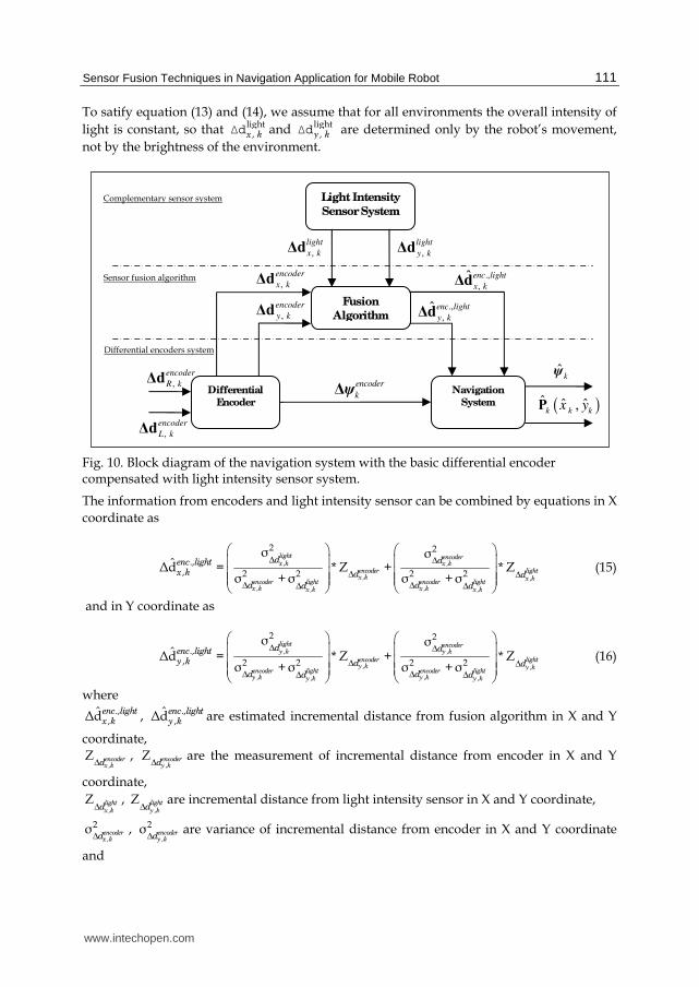
To satify equation (13) and (14), we assume that for all environments the overall intensity of
light is constant, so that light, x kΔd and light
, y kΔd are determined only by the robot’s movement,
not by the brightness of the environment.
Fig. 10. Block diagram of the navigation system with the basic differential encoder compensated with light intensity sensor system.
The information from encoders and light intensity sensor can be combined by equations in X
coordinate as
, ,
, ,
, ,, ,
2 2
.,, 2 2 2 2
σ σˆΔd = * Z + * Z
σ +σ σ +σ
light encoderx k x k
encoder lightx k x k
encoder light encoder lightx k x kx k x k
d denc lightx k d d
d dd d
Δ Δ
Δ Δ
Δ ΔΔ Δ
(15)
and in Y coordinate as
, ,
, ,
, ,, ,
2 2
.,, 2 2 2 2
σ σˆΔd = * Z + * Z
σ +σ σ +σ
light encodery k y k
encoder lighty k y k
encoder light encoder lighty k y ky k y k
d denc lighty k d d
d dd d
Δ Δ
Δ Δ
Δ ΔΔ Δ
(16)
where .,
,ˆΔdenc light
x k , .,,
ˆΔdenc lighty k are estimated incremental distance from fusion algorithm in X and Y
coordinate,
,Z encoder
x kdΔ,
,Z encoder
y kdΔare the measurement of incremental distance from encoder in X and Y
coordinate,
,
Z lightx kdΔ
, ,
Z lighty kdΔ
are incremental distance from light intensity sensor in X and Y coordinate,
,
2σ encoderx kdΔ
, ,
2σ encodery kdΔ
are variance of incremental distance from encoder in X and Y coordinate
and
Differential encoders system
Sensor fusion algorithm
Complementary sensor system
,
encoder
R kΔd
,
encoder
L kΔd
Differential
Encoder
Fusion
Algorithm
,
encoder
x kΔd
,
encoder
y kΔd
Light Intensity
Sensor System
Navigation
System ( )ˆ ˆ ˆ,k k kx yP
ˆkψ
ψencoder
kΔ
,
light
x kΔd
,
light
y kΔd
.,
, ˆ enc light
x kΔd
.,
, ˆ enc light
y kΔd
www.intechopen.com
Sensor Fusion - Foundation and Applications
112
,
2σ lightx kdΔ
,,
2σ lighty kdΔ
are variance of incremental distance from light intensity sensor in X and Y
coordinate.
3.4 Sensor fusion between differential encoder as basic system of mobile robot and compass as absolute complementary system of orientation Absolute positioning systems use the geometry relation between the position and
environment map (Byoung-Suk Choi, 2009). Some methods have been proposed for robot
position reference. One of them has designed landmarks placed at specified positions with
respect to the reference coordinate system. The current position and orientation of the robot
can be obtained by geometry transformations between robot sensors and these landmarks.
Kabuka and Arenas (1987) researched on absolute positioning by using barcodes. Kim
(1996) described the experiments on orientation recovery of mobile robot by using compass.
Ojeda, L. (2000) discussed on the use of electronic compasses in mobile robots with different
error sources and solutions to correct these errors. From the geometry measurement the
Cartesian coordinates (X, Y, θ) can be specified under certain assumption. If the position of
the geometry reference is known, the position of mobile robot can be calculated usually with
good accuracy. The compass can generate direct the output of absolute orientation ψcompassk
located at the mobile robot’s center.
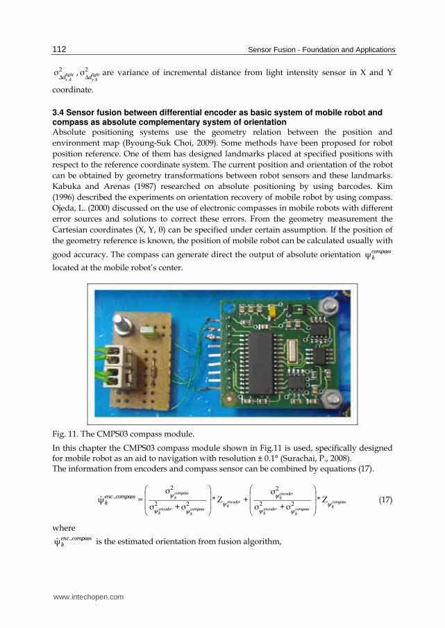
Fig. 11. The CMPS03 compass module.
In this chapter the CMPS03 compass module shown in Fig.11 is used, specifically designed for mobile robot as an aid to navigation with resolution ± 0.1° (Surachai, P., 2008). The information from encoders and compass sensor can be combined by equations (17).
2 2
.,
2 2 2 2
σ σψ = * Z + * Z
σ +σ σ +σ
compass encoderk k
encoder compassk k
encoder compass encoder compassk kk k
enc compassk
ψ ψ
ψ ψψ ψψ ψ
(17)
where .,ψenc compass
k is the estimated orientation from fusion algorithm,
www.intechopen.com
Sensor Fusion Techniques in Navigation Application for Mobile Robot
113
Z encoderkψ
is the measurement of orientation read from navigation system of differential
encoder system,
Z compasskψ
is the measurement of orientation read from compass,
2σ encoderkψ
is variance of the measurement of orientation read from navigation system of
differential encoder system and 2σ compass
kψ is variance of the measurement of orientation read from compass.
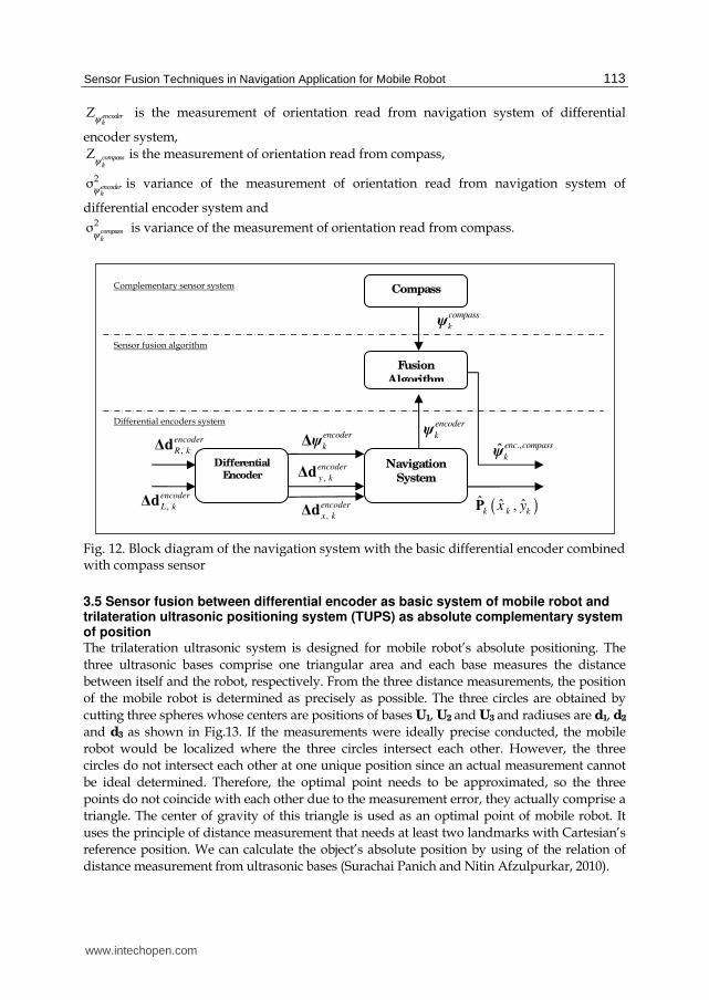
Fig. 12. Block diagram of the navigation system with the basic differential encoder combined with compass sensor
3.5 Sensor fusion between differential encoder as basic system of mobile robot and trilateration ultrasonic positioning system (TUPS) as absolute complementary system of position The trilateration ultrasonic system is designed for mobile robot’s absolute positioning. The
three ultrasonic bases comprise one triangular area and each base measures the distance
between itself and the robot, respectively. From the three distance measurements, the position
of the mobile robot is determined as precisely as possible. The three circles are obtained by
cutting three spheres whose centers are positions of bases U1, U2 and U3 and radiuses are d1, d2
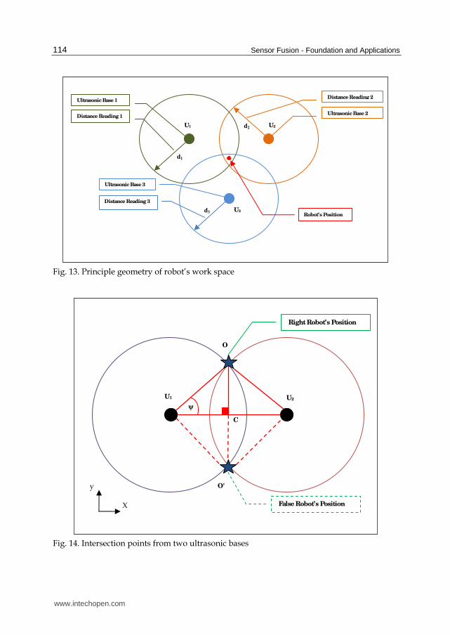
and d3 as shown in Fig.13. If the measurements were ideally precise conducted, the mobile
robot would be localized where the three circles intersect each other. However, the three
circles do not intersect each other at one unique position since an actual measurement cannot
be ideal determined. Therefore, the optimal point needs to be approximated, so the three
points do not coincide with each other due to the measurement error, they actually comprise a
triangle. The center of gravity of this triangle is used as an optimal point of mobile robot. It
uses the principle of distance measurement that needs at least two landmarks with Cartesian’s
reference position. We can calculate the object’s absolute position by using of the relation of
distance measurement from ultrasonic bases (Surachai Panich and Nitin Afzulpurkar, 2010).
,
encoder
R kΔd
,
encoder
L kΔd
Differential
Encoder
Fusion
Algorithm
,
encoder
x kΔd
,
encoder
y kΔd
Compass
.,ψenc compass
k Navigation
System
( )ˆ ˆ ˆ,k k kx yP
ψencoder
kΔ
ψcompass
k
Differential encoders system
Sensor fusion algorithm
Complementary sensor system
ψencoder
k
www.intechopen.com
Sensor Fusion - Foundation and Applications
114
Fig. 13. Principle geometry of robot’s work space
Fig. 14. Intersection points from two ultrasonic bases
U1 U2
Right Robot’s Position
ψ
O
C
O'
False Robot’s Position X
y
U1 U2
U3 Robot’s Position
Ultrasonic Base 2
Ultrasonic Base 1
Ultrasonic Base 3
Distance Reading 1
Distance Reading 3
Distance Reading 2
d1
d2
d3
www.intechopen.com
Sensor Fusion Techniques in Navigation Application for Mobile Robot
115
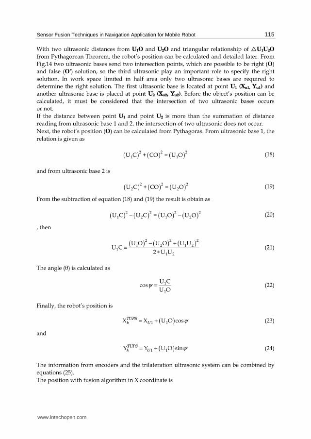
With two ultrasonic distances from U1O and U2O and triangular relationship of U1U2O
from Pythagorean Theorem, the robot’s position can be calculated and detailed later. From
Fig.14 two ultrasonic bases send two intersection points, which are possible to be right (O)
and false (O') solution, so the third ultrasonic play an important role to specify the right
solution. In work space limited in half area only two ultrasonic bases are required to
determine the right solution. The first ultrasonic base is located at point U1 (Xu1, Yu1) and
another ultrasonic base is placed at point U2 (Xu2, Yu2). Before the object’s position can be
calculated, it must be considered that the intersection of two ultrasonic bases occurs
or not.
If the distance between point U1 and point U2 is more than the summation of distance
reading from ultrasonic base 1 and 2, the intersection of two ultrasonic does not occur.
Next, the robot’s position (O) can be calculated from Pythagoras. From ultrasonic base 1, the
relation is given as
( ) ( ) ( )2 2 2
1 1U C + CO = U O (18)
and from ultrasonic base 2 is
( ) ( ) ( )2 2 2
2 2U C + CO = U O (19)
From the subtraction of equation (18) and (19) the result is obtain as
( ) ( ) ( ) ( )2 2 2 2
1 2 1 2U C U C = U O U O− − (20)
, then
( ) ( ) ( )
2 2 21 2 1 2
11 2
U O U O U UU C
2 U U
− +=
∗ (21)
The angle (θ) is calculated as
1
1
U Ccos
U Oψ = (22)
Finally, the robot’s position is
( )1 1X X U O cosTUPSk U ψ= + (23)
and
( )1 1Y Y U O sinTUPSk U ψ= + (24)
The information from encoders and the trilateration ultrasonic system can be combined by
equations (25).
The position with fusion algorithm in X coordinate is
www.intechopen.com
Sensor Fusion - Foundation and Applications
116
2 2
.,2 2 2 2
σ σX = * Z + * Z
σ +σ σ +σ
TUPS encoderk k
encoder TUPSk k
encoder TUPS encoder TUPSk k k k
x xenc TUPSk x x
x x x x
(25)
and the position with fusion algorithm in Y coordinate is
2 2
.,2 2 2 2
σ σY = * Z + * Z
σ +σ σ +σ
TUPS encoderk k
encoder TUPSk k
encoder TUPS encoder TUPSk k k k
y yenc TUPSk y y
y y y y
(26)
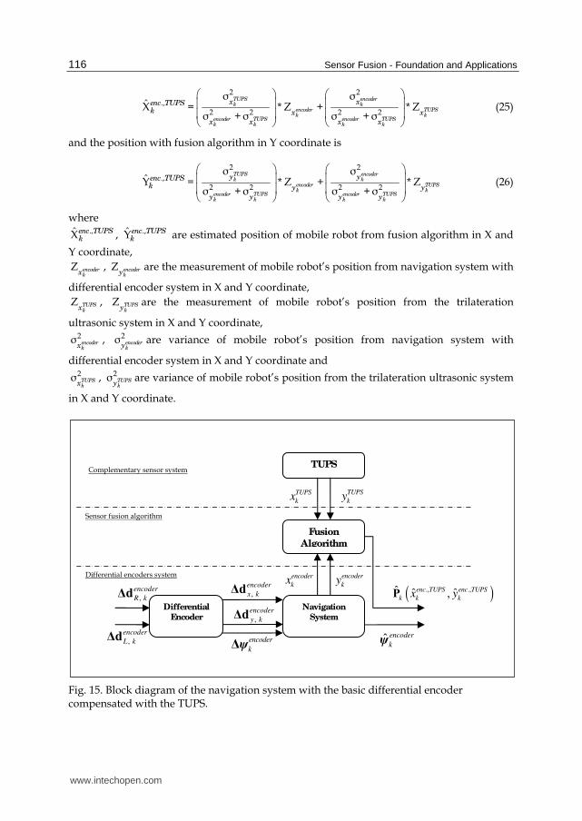
where .,Xenc TUPS
k , .,Yenc TUPSk are estimated position of mobile robot from fusion algorithm in X and
Y coordinate,
Z encoderkx
, Z encoderky
are the measurement of mobile robot’s position from navigation system with
differential encoder system in X and Y coordinate,
Z TUPSkx
, Z TUPSky
are the measurement of mobile robot’s position from the trilateration
ultrasonic system in X and Y coordinate, 2σ encoder
kx, 2σ encoder
kyare variance of mobile robot’s position from navigation system with
differential encoder system in X and Y coordinate and 2σ TUPS
kx, 2σ TUPS
kyare variance of mobile robot’s position from the trilateration ultrasonic system
in X and Y coordinate.
Fig. 15. Block diagram of the navigation system with the basic differential encoder compensated with the TUPS.
Differential encoders system
Sensor fusion algorithm
Complementary sensor system
,
encoder
R kΔd
,
encoder
L kΔd
Differential
Encoder
Fusion
Algorithm
,
encoder
x kΔd
,
encoder
y kΔd
TUPS
ψencoder
k
Navigation
System
( )., .,ˆ ˆ ˆ,enc TUPS enc TUPS
k k kx yP
ψencoder
kΔ
encoder
kx
encoder
ky
TUPS
kx
TUPS
ky
www.intechopen.com
Sensor Fusion Techniques in Navigation Application for Mobile Robot
117
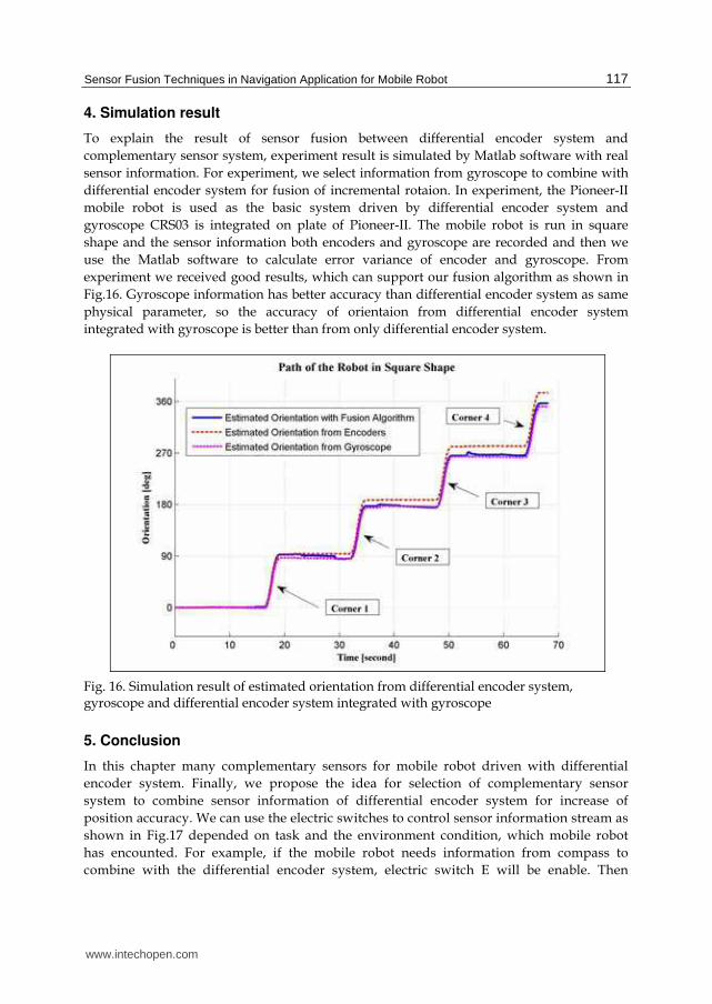
4. Simulation result
To explain the result of sensor fusion between differential encoder system and
complementary sensor system, experiment result is simulated by Matlab software with real
sensor information. For experiment, we select information from gyroscope to combine with
differential encoder system for fusion of incremental rotaion. In experiment, the Pioneer-II
mobile robot is used as the basic system driven by differential encoder system and
gyroscope CRS03 is integrated on plate of Pioneer-II. The mobile robot is run in square
shape and the sensor information both encoders and gyroscope are recorded and then we
use the Matlab software to calculate error variance of encoder and gyroscope. From
experiment we received good results, which can support our fusion algorithm as shown in
Fig.16. Gyroscope information has better accuracy than differential encoder system as same
physical parameter, so the accuracy of orientaion from differential encoder system
integrated with gyroscope is better than from only differential encoder system.
Fig. 16. Simulation result of estimated orientation from differential encoder system, gyroscope and differential encoder system integrated with gyroscope
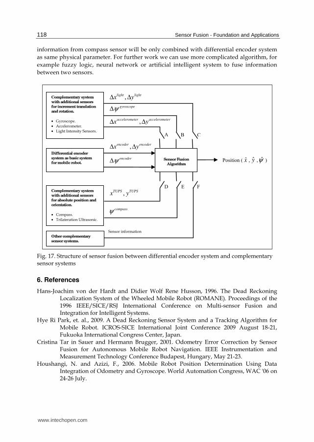
5. Conclusion
In this chapter many complementary sensors for mobile robot driven with differential
encoder system. Finally, we propose the idea for selection of complementary sensor
system to combine sensor information of differential encoder system for increase of
position accuracy. We can use the electric switches to control sensor information stream as
shown in Fig.17 depended on task and the environment condition, which mobile robot
has encounted. For example, if the mobile robot needs information from compass to
combine with the differential encoder system, electric switch E will be enable. Then
www.intechopen.com
Sensor Fusion - Foundation and Applications
118
information from compass sensor will be only combined with differential encoder system
as same physical parameter. For further work we can use more complicated algorithm, for
example fuzzy logic, neural network or artificial intelligent system to fuse information
between two sensors.
Fig. 17. Structure of sensor fusion between differential encoder system and complementary sensor systems
6. References
Hans-Joachim von der Hardt and Didier Wolf Rene Husson, 1996. The Dead Reckoning Localization System of the Wheeled Mobile Robot (ROMANE). Proceedings of the 1996 IEEE/SICE/RSJ International Conference on Multi-sensor Fusion and Integration for Intelligent Systems.
Hye Ri Park, et. al., 2009. A Dead Reckoning Sensor System and a Tracking Algorithm for Mobile Robot. ICROS-SICE International Joint Conference 2009 August 18-21, Fukuoka International Congress Center, Japan.
Cristina Tar in Sauer and Hermann Brugger, 2001. Odometry Error Correction by Sensor Fusion for Autonomous Mobile Robot Navigation. IEEE Instrumentation and Measurement Technology Conference Budapest, Hungary, May 21-23.
Houshangi, N. and Azizi, F., 2006. Mobile Robot Position Determination Using Data Integration of Odometry and Gyroscope. World Automation Congress, WAC '06 on 24-26 July.
Sensor Fusion
Algorithm
Complementary system
with additional sensors
for increment translation
and rotation.
• Gyroscope.
• Accelerometer.
• Light Intensity Sensors.
Differential encoder
system as basic system
for mobile robot.
Complementary system
with additional sensors
for absolute position and
orientation.
• Compass.
• Trilateration Ultrasonic.
Position ( x , y ,ψ ) encoderψΔ
,Δ Δencoder encoderx y
gyroscopeψΔ
,Δ Δaccelerometer accelerometerx y
,Δ Δlight lightx y
compassψ
A B C
D E F
,TUPS TUPSx y
Other complementary
sensor systems.
Sensor information
www.intechopen.com
Sensor Fusion Techniques in Navigation Application for Mobile Robot
119
Agostino Martinelli, 2002. The Odometry Error of a Mobile Robot with a Synchronous Drive System IEEE Transactions on Robotics and Automation, Vol. 18, No. 3, June.
Komoriya, K. and Oyama, E., 1994. Position estimation of a mobile robot using optical fiber gyroscope (OFG). Intelligent Robots and Systems, Advanced Robotic Systems and the Real World, IROS '94. Proceedings of the IEEE/RSJ/GI International Conference on 12-16 Sept. 1994.
Yikang Yang, Yong Lin and Yongxuan Huang, 2002. The Navigation Principle and Algorithm of Vehicular Dead Reckoning System with Differential Compass. Proceedings of the 4th World Congress an Intelligent Control and Automation, June 10-14, Shanghai, P.R.China.
Miao Yu and Li Shu-qin, 2010. A Method of Robot Navigation Based on the Multi-Sensor Fusion. Intelligent Systems and Applications (ISA), 2nd International Workshop on 22-23 May, DOI: 10.1109/IWISA.2010.5473355
Tao Guo and Silamu, W., 2009. A fuzzy logic information fusion algorithm for autonomous mobile robot avoidance based on multi-ultrasonic range sensors. Joint Conference of the 2009 Symposium on Piezoelectricity, Acoustic Waves, and Device Applications (SPAWDA) and Control Technology,
DOI: 10.1109/SPAWDA.2009.5428888, Page(s): 84 - 84 Zhang, J., Wu, Y., Liu, W., Chen, X., 2010. Novel Approach to Position and Orientation
Estimation in Vision-Based UAV Navigation. IEEE Transactions on Aerospace and Electronic Systems, Volume: 46 , Issue: 2 DOI: 10.1109/TAES.2010.5461649 , Page(s): 687 - 700
Chen, Yen-Sheng, Wang, Wei-Hsun, Juang, Jih-Gau, 2010. Application of intelligent computing to autonomous vehicle control. IEEE Congress on Evolutionary Computation (CEC). DOI: 10.1109/CEC.2010.5586475, Page(s): 1 – 8
Surachai, P.; Thiraporn, T.; Chaiyaporn, L.; Kittichai, T.; Tayawat, S., 2009. Sensor fusion for differential encoder integrated with light intensity sensors and accelerometer. 2009 IEEE International Symposium on Computational Intelligence in Robotics and Automation (CIRA), DOI: 10.1109/CIRA.2009.5423180, Page(s): 349 – 354
Gelb (1974). Applied Optimal Estimation. MIT Press, Massachusetts Institute of Technology Cambridge, Massachusetts 02142
Srinivasan, K. and Gu, J. Multiple Sensor Fusion in Mobile Robot Localization, Electrical and Computer Engineering, 2007. CCECE 2007 Canadian Conference on, 22-26 April 2007 Page(s): 1207 - 1210
Byoung-Suk Choi (2009). Mobile Robot Localization in Indoor Environment using RFID and Sonar Fusion System, IEEE/RSJ International Conference on Intelligent Robots and
Systems, October 11-15, 2009 St. Louis, USA Kakuba and Arenas (1987). Position Verification of a Mobile Robot Using Standard Pattern”
IEEE Journal of Robotics and Automation, vol. RA-3, NO.6, December. Ojeda, L. and Borenstein, J. (2000). Experimental Results with the KVH C-100 Fluxgate
Compass in Mobile Robots, Proceedings of the IASTED International Conference
Robotics and Applications, August 14-16, 2000 – Honolulu, Hawaii, USA. Panich, S. (2008). A mobile robot with an inter-integrated circuit system, 10th International
Conference on Control, Automation, Robotics and Vision, Publication Year: 2008, Page(s): 2010 – 2014, Digital Object Identifier: 10.1109/ICARCV.2008.4795839
www.intechopen.com

Sensor Fusion - Foundation and Applications
120
Surachai Panich (2010a). Mobile Robot Driven by Odometry System Integrated with Accelerometer. Far East Journal of Electronics and Communications, Volume 4, Issue 2 (June 2010) Page: 113 – 122
Surachai Panich (2010b). Dynamics, Control and Simulation of Robots with Differential Drive Integrated with Light Intensity Sensors. Far East Journal of Dynamical Systems, Volume 13, Issue 2 (July 2010) Page: 157 – 164
Surachai Panich and Nitin Afzulpurkar (2010). Absolute Positioning Instruments for Odometry System Integrated with Gyroscope by Using IKF, Global Journal of
Researches in Engineering, Vol.10 Issue 4 (Ver 1.0) , September 2010, pp:63-74
www.intechopen.com
Sensor Fusion - Foundation and ApplicationsEdited by Dr. Ciza Thomas
ISBN 978-953-307-446-7Hard cover, 226 pagesPublisher InTechPublished online 24, June, 2011Published in print edition June, 2011
InTech EuropeUniversity Campus STeP Ri Slavka Krautzeka 83/A 51000 Rijeka, Croatia Phone: +385 (51) 770 447 Fax: +385 (51) 686 166www.intechopen.com
InTech ChinaUnit 405, Office Block, Hotel Equatorial Shanghai No.65, Yan An Road (West), Shanghai, 200040, China
Phone: +86-21-62489820 Fax: +86-21-62489821
Sensor Fusion - Foundation and Applications comprehensively covers the foundation and applications ofsensor fusion. This book provides some novel ideas, theories, and solutions related to the research areas inthe field of sensor fusion. The book explores some of the latest practices and research works in the area ofsensor fusion. The book contains chapters with different methods of sensor fusion for different engineering aswell as non-engineering applications. Advanced applications of sensor fusion in the areas of mobile robots,automatic vehicles, airborne threats, agriculture, medical field and intrusion detection are covered in this book.Sufficient evidences and analyses have been provided in the chapter to show the effectiveness of sensorfusion in various applications. This book would serve as an invaluable reference for professionals involved invarious applications of sensor fusion.
How to referenceIn order to correctly reference this scholarly work, feel free to copy and paste the following:
Surachai Panich and Nitin Afzulpurkar (2011). Sensor Fusion Techniques in Navigation Application for MobileRobot, Sensor Fusion - Foundation and Applications, Dr. Ciza Thomas (Ed.), ISBN: 978-953-307-446-7,InTech, Available from: http://www.intechopen.com/books/sensor-fusion-foundation-and-applications/sensor-fusion-techniques-in-navigation-application-for-mobile-robot

© 2011 The Author(s). Licensee IntechOpen. This chapter is distributedunder the terms of the Creative Commons Attribution-NonCommercial-ShareAlike-3.0 License, which permits use, distribution and reproduction fornon-commercial purposes, provided the original is properly cited andderivative works building on this content are distributed under the samelicense.