Embed Size (px)
Citation preview
Sensorless Action-reaction-based Residual Vibration
Suppression for Multi-degree-of-freedom Flexible
Systems
Islam S. M. Khalil and Asif Sabanovic
School of Engineering and Natural Sciences
Sabanci University
Istanbul, Turkey 34956
Email: kahalil, [email protected]
Telephone: (+90) 216–4839502
Fax: (+90) 216–4839550
Abstract—This paper demonstrates the feasibility of control-ling motion and vibration of a class of flexible systems withinaccessible or unknown outputs through measurements takenfrom their actuators which are used as single platforms formeasurements, whereas flexible dynamical systems are kept freefrom any attached sensors. Based on the action reaction lawof dynamics, the well-known disturbance observer is used todetermine the incident reaction forces from these dynamicalsystems on the interface planes with their actuators. Reactionforces are considered as feedback-like signals that can be usedas alternatives to the inaccessible system outputs. The sensorlessaction reaction based motion and vibration control technique isimplemented on a flexible system with finite modes and all resultsare verified experimentally.
I. INTRODUCTION
Desire for systems with high speeds, lighter weights and
less powerful actuators became significant for majority of
nowadays design specifications. On one hand, these flexible
systems have numerous advantages over rigid ones. On the
other hand, their actuators must attempt to satisfy two de-
mands, namely motion control and active residual vibration
suppression. The problem of controlling motion and vibration
of flexible systems was extensively studied over the past
few decades. However, outputs of these systems are assumed
accessible or known. This work is concerned with motion
control and active vibration suppression of a class of flexible
systems with inaccessible outputs.
Much effort has been expended to suppress flexible system’s
residual vibration, the most common technique for reducing
residual vibration is to pre-filter the control input using either
a low-pass or a notch filter [1]-[2] in order to take away
any energy at system’s resonant frequencies such that the
flexible modes will not be excited. Point-to-point motion
control is capable of achieving zero residual vibration if the
control input waveform succeeded to eliminate any kinetic and
potential energy from the elastic elements at the end of the
travel [3]-[4]. Introducing additional switching times to the
conventional bang-bang control input eliminates the undesired
residual vibrations for non-rigid systems [5]-[6]. A novel Pre-
shaping technique was proposed in [7] for eliminating residual
vibration, based on convolving an arbitrary control signal with
a sequence of impulses chosen such that it would not cause
residual vibration in the absence of control input. Minimum
Energy control of residual vibration was proposed in [9] by
imposing additional constrain to the optimal control problem
to guarantee the uniqueness of the control law. However, the
minimum energy control ignores the higher frequency reso-
nances which would contribute to residual vibration. Cooper
and Skaar [10] mentioned that this problem can be alleviated
if the control input was to be a minimum ”Jerk” rather than a
”minimum energy solution”.
Each of the previous vibration control technique has special
characteristics and drawbacks. None is completely satisfactory
under all headings. Furthermore, they all depend on the
availability of system states or outputs by either using sensors
to measure each state variable or by designing state observers
based on availability of system outputs.
A question naturally arises: can we realize motion and vibra-
tion suppression control if system outputs are inaccessible and
non of them can be measured for certain reasons ? This work
presents a motion control and active vibration suppression
framework based on realization of the action reaction law of
dynamics to control motion and vibration of flexible structures
with finite or infinite modes through measurements taken from
their actuators.
The proposed algorithm depends on two measurements
from the actuator keeping the flexible system free from any
additional measurement. Therefore, the word ”Sensorless”
refers to the flexible plant excluding the actuator, these two
measurements are used as inputs to the well-known distur-
bance observer [12]-[13]. Then disturbance observer structure
is modified in order to decouple incident reaction forces from
flexible system out of the total disturbance [14]-[15]. Reaction
forces are conceptually considered as feedback-like signals
which can be used as alternatives to the system inaccessible
outputs.
Remainder of this paper is organized as follows, Section II
includes a design procedure of an action reaction state observer
to estimate system states from measurements taken from the
actuator side. Motion and vibration suppression control law
is realized in Section III. Experimental results which are
conducted on a flexible system with 3-dof are included in
Section IV. Eventually, conclusions and final remarks are
discussed in Section V.
II. ACTION REACTION STATE OBSERVER
The class of dynamical flexible system with inaccessible
outputs that we consider is modeled by
x = Ax + Bu , y = Cx (1)
where x ∈ Rn and y ∈ Rm are the state and measurement
vectors, respectively. A ∈ Rn×n, B ∈ Rn×1 and C ∈ R1×n
are the system matrix, distribution vector of input and obser-
vation column vector, respectively. We assume that system (1)
has a single input u. It can be shown that system (1) can be
partitioned as follows
xa = Aaxa + Baua + Breacfreac(x, x) (2)
xp = Apxp + Bpfreac(x, x)
where xa and xp are actuator and plant state vectors, respec-
tively. The subscripts (a) and (p) denote the actuator and plant.
freac(x, x) is the incident instantaneous reaction force on the
actuator, Breac is the reaction force distribution vector. For
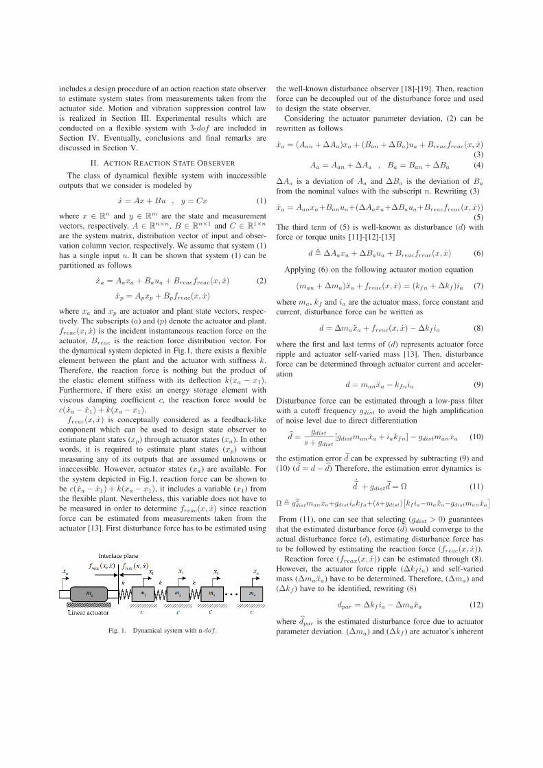
the dynamical system depicted in Fig.1, there exists a flexible
element between the plant and the actuator with stiffness k.
Therefore, the reaction force is nothing but the product of
the elastic element stiffness with its deflection k(xa − x1).Furthermore, if there exist an energy storage element with
viscous damping coefficient c, the reaction force would be
c(xa − x1) + k(xa − x1).freac(x, x) is conceptually considered as a feedback-like
component which can be used to design state observer to
estimate plant states (xp) through actuator states (xa). In other
words, it is required to estimate plant states (xp) without
measuring any of its outputs that are assumed unknowns or
inaccessible. However, actuator states (xa) are available. For
the system depicted in Fig.1, reaction force can be shown to
be c(xa − x1) + k(xa − x1), it includes a variable (x1) from
the flexible plant. Nevertheless, this variable does not have to
be measured in order to determine freac(x, x) since reaction
force can be estimated from measurements taken from the
actuator [13]. First disturbance force has to be estimated using
Fig. 1. Dynamical system with n-dof .
the well-known disturbance observer [18]-[19]. Then, reaction
force can be decoupled out of the disturbance force and used
to design the state observer.
Considering the actuator parameter deviation, (2) can be
rewritten as follows
xa = (Aan + ∆Aa)xa + (Ban + ∆Ba)ua + Breacfreac(x, x)(3)
Aa = Aan + ∆Aa , Ba = Ban + ∆Ba (4)
∆Aa is a deviation of Aa and ∆Ba is the deviation of Ba
from the nominal values with the subscript n. Rewriting (3)
xa = Aanxa+Banua+(∆Aaxa+∆Baua+Breacfreac(x, x))(5)
The third term of (5) is well-known as disturbance (d) with
force or torque units [11]-[12]-[13]
d , ∆Aaxa + ∆Baua + Breacfreac(x, x) (6)
Applying (6) on the following actuator motion equation
(man + ∆ma)xa + freac(x, x) = (kfn + ∆kf )ia (7)
where ma, kf and ia are the actuator mass, force constant and
current, disturbance force can be written as
d = ∆maxa + freac(x, x) − ∆kf ia (8)
where the first and last terms of (d) represents actuator force
ripple and actuator self-varied mass [13]. Then, disturbance
force can be determined through actuator current and acceler-
ation
d = manxa − kfnia (9)
Disturbance force can be estimated through a low-pass filter
with a cutoff frequency gdist to avoid the high amplification
of noise level due to direct differentiation
d =gdist
s + gdist
[gdistmanxa + iakfn] − gdistmanxa (10)
the estimation error d can be expressed by subtracting (9) and
(10) (d = d − d) Therefore, the estimation error dynamics is
˙d + gdistd = Ω (11)
Ω , g2
distmanxa+gdistiakfa+(s+gdist)[
kf ia−maxa−gdistmanxa
]
From (11), one can see that selecting (gdist > 0) guarantees
that the estimated disturbance force (d) would converge to the
actual disturbance force (d), estimating disturbance force has
to be followed by estimating the reaction force (freac(x, x)).Reaction force (freax(x, x)) can be estimated through (8).
However, the actuator force ripple (∆kf ia) and self-varied
mass (∆maxa) have to be determined. Therefore, (∆ma) and
(∆kf ) have to be identified, rewriting (8)
dpar = ∆kf ia − ∆maxa (12)
where dpar is the estimated disturbance force due to actuator
parameter deviation. (∆ma) and (∆kf ) are actuator’s inherent
properties. Therefore, they can be identified from the actuator
through (12) [14]-[15].
[kf −ma
]1×2
[ia
xa
]
2×r
=[
dpar
](13)
[kf −ma
]= H
†[
dpar
], H ,
[im xa
]T
(14)
Matrix H consists of two vectors, actuator current (ia) and
acceleration data points (xa). H† is the pseudo inverse of H.
rewriting (8) using estimated disturbance force and identified
parameters obtained through (10) and (15), respectively.
d = ∆maxa + freac(x, x) − ∆kf ia (15)
Similar to (10), reaction force can be estimated through the
following low-pass filter with cutoff frequency g
freac(x, x) =g
s + g[g∆maxa + ia∆kf + d]−g∆maxa (16)
Similar to the well-known Luenberger observer, structure of
the action reaction state observer can be written as follows
˙x = Ax + Bu + M(freac(x, x) − freac(x, ˙x)
)(17)
freac(x, x) is the estimated reaction force which can be
obtained through (16) while freac(x, ˙x) is the reaction force
computed using the estimated states (x)
freac(x, ˙x) = c(xa − ˙x1) + k(xa − x1) (18)
M is the observer gain vector. It is at least intuitively clear
that, observability of system (1) has to be analyzed when
measurements are only allowed to be taken from the actuator
which implies that the observation vector can be written as
C =[
1 1 0 · · · 0]
(19)
The change of coordinates x = Tξ transforms the system (1)
into the form
ξ = T−1ATξ + T−1Bu = Aξ + Bu (20)
y = CTξ = Cξ
selecting the non-singular matrix T as
T =
1 1 1 . . . 1
λ1 λ2 λ3 . . . λn
λ21 λ2
2 λ23 . . . λ2
n
......
.... . .
...
λn−11 λn−1
2 λn−13 . . . λn−1
n
(21)
guarantees that system (20) has a diagonal form. Where,
λ1, . . . , λn are the eigenvalues of the system matrix A. Here-
after, system (20) can be written in the following form
[ξa
ξp
]=
[Aa φ
φ Ap
] [ξa
ξp
]+
[Ba
Bp
]u (22)
Aa and Ap are the actuator and plant diagonal system matrices,
respectively. Ba and Bp are the actuator and plant input
distribution vectors. respectively.
A regular procedure for estimating states of the flexible
plant depicted in Fig.1 is to measure some of its states
(xp = Tξp), then using these measurements to design state
observer. In this work, plant states (xp) are assumed inacces-
sible. However, the reaction force freac(x, x) is conceptually
considered as a natural feedback from the plant on the actuator
and therefore used as an alternative to any measurement from
the plant required to design the state observer. Computing C
C =[
1 + λ1 1 + λ2 1 + λ3 . . . 1 + λn
](23)
taking the time derivatives of the output equation of system
(20) we obtain the following matrix equation
y
y
y...y
...
︸︷︷ ︸ℵ(y)
=
C
CA
CA2
CA3
...
︸ ︷︷ ︸O
ξ +
0 0 0 0 · · ·
CB 0 0 0 · · ·
CAB CB 0 0 · · ·
CA2B CAB CB 0 · · ·
......
......
. . .
︸ ︷︷ ︸Γ
u
u
u...u
...
︸︷︷ ︸ℵ(u)
(24)
Putting (24) in the following compact form
ℵ(y) = O ξ + Γ ℵ(u) (25)
where ℵ(y) and ℵ(u) are the Nordsieck vectors of the output
and the input, respectively.Computing the observability matrix O using (23) and (24),
we obtain
O =
1 + λ1 1 + λ2 1 + λ3 . . . 1 + λn−1
λ1 + λ2
1 λ2 + λ2
2 λ3 + λ2
3 . . . λn−1 + λ2
n−1
λ2
1 + λ3
1 λ2
2 + λ3
2 λ2
3 + λ3
3 . . . λ2
n−1 + λ3
n−1
......
.... . .
...
λn−1
1+ λn
1 λn−1
2+ λn
2 λn−1
3+ λn
3 . . . λn−1
n + λnn
(26)
It can be easily shown that O is full ranked if all eigenvalues
of the system matrix A are distinct. Therefore, plant states (xp)
can be observed from measurements taken from the actuator
(xa) under the condition that all eigenvalues of A are distinct.
The similarity transformation xp = Tξp allows obtaining the
unique structure of the observability matrix O. Now from (1)
and (17), estimation error is e = x − x, thus error dynamics
is governed by
e = (I − cML)−1(A + kML)e = Ae (27)
L = [1 0 · · · 0]
Therefore, estimation error (e) will converge to zero if all
eigenvalues of (A = (I − cML)−1(A + kML)) lie on the
left-half plane. Selection of the observer gain (M) is a regular
pole placement problem. It can be shown now that the state
observer (17) does not necessitate taking any measurement

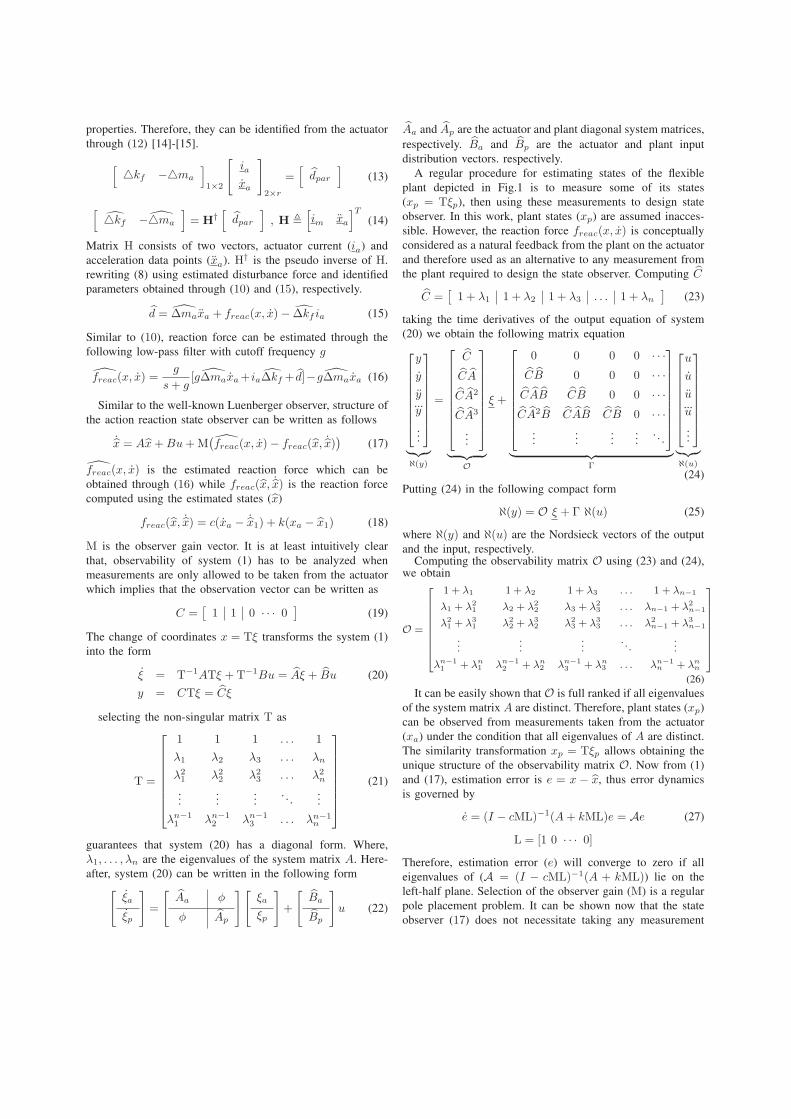
Fig. 2. Action reaction state observer.
from the plant side, plant states (xp) are not measured at all.
However, the incident reaction force is conceptually consid-
ered as a natural feedback from the sensorless plant. Thus,
used to design the state observer (17) which only requires two
measurements from the actuator to estimate disturbance and
reaction forces through (10) and (16), respectively. The action
reaction state observer is depicted in Fig.2 where flexible plant
is kept free from any measurement except the reaction force
that is estimated through actuator variables and considered as
a single feedback from the flexible plant.
III. MOTION AND VIBRATION SUPPRESSION CONTROL
In order to achieve vibrationless point-to-point motion con-trol of the flexible lumped system depicted in Fig.1, the endconditions have to be
ξ |t=T =
ξa
0
...
0
, ξ |t=T =
0
0
...
0
(28)
which indicates that in order to achieve vibrationless motion
control manoeuvre, potential and kinetic energy have to vanish
at the end of the travel (t = T ). Solution of (20) can be
expressed in terms of the following convolution integral [1]
ξ(t) = ξ(0)eAt +
∫ t
0
eA(t−τ).Bu(τ)dτ (29)
assuming zero initial condition and replacing the actual state
(x = Tξ) with the estimated ones (x = Tξ) obtained through
(17)
e−Atξ(t) =
∫ t
0
eA(−τ).Bu(τ)dτ (30)
Using constrain equation (30) to determine the control u
which minimizes the energy content of the flexible plant.
Therefore, the performance index can be expressed as
J =
∫ t
0
|u|2dτ + λT
[e−Atξ(t) −
∫ t
0
e−Aτ .Bu(τ)dτ
](31)
where λ is a vector of Lagrange multipliers. Variation δJ can
be shown to be
δJ =
∫ t
0
[2u∗ − λT e−Aτ .B
]δu dτ (32)
the variation δJ will vanish if the integrand of (32) is zero.
Therefore, the control u is
u =1
2λT e−A∗t.B (33)
Equation (33) along with the estimated states obtained through
(17) allow controlling motion and vibration of any non-
collocated mass along the flexible plant from measurements
taken from its actuator. In (33), the control law is depending
on the Lagrange multipliers which can be computed from the
estimated states obtained through (17).

(a) Microsystems workstation (b) Flexible plant with 3-dof
Fig. 3. Experimental setup.
2 2.2 2.4 2.6 2.8 30
0.05
0.1
0.15
0.2
0.25
0.3
Time (secs)
Position (mm)
x3
x3
(a) x1 vs. x1
2 2.2 2.4 2.6 2.8 30
0.05
0.1
0.15
0.2
0.25
0.3
Time (secs)
Position (mm)
x5
x5
(b) x3 vs. x3
2 2.2 2.4 2.6 2.8 30
0.05
0.1
0.15
0.2
0.25
0.3
Time (secs)
Position (mm)
x7
x7
(c) x5 vs. x5
Fig. 4. Experimental states estimation results of a dynamical system with 3-dof (x3, x5 and x7 represent first, second and third masses positions, respectively).
11.3 11.4 11.5 11.6 11.7 11.8 11.9 12
−0.4
−0.3
−0.2
−0.1
0
0.1
Time (sec)
Position (mm)
Estimated position
Actual position (Non−collocated 2nd mass)
Reference (475 µm)
A−A
(a) Response of the 2nd non-collocated mass to a 475µm
reference input
11.25 11.3 11.35 11.4 11.45 11.5 11.55 11.6
−0.2
−0.1
0
0.1
Time (sec)
Position (mm)
A−A
(b) Magnified plot
Fig. 5. Sensorless vibrationless motion control experimental result of the 2nd non-collocated mass.
IV. EXPERIMENTAL RESULTS
Experiments are conducted on a flexible system with 3-
dof as depicted in Fig.3. The experimental setup consists of a
microscope mounted on the top of the 3-dof flexible system. A
linear actuator is used as a single platform for measurements.
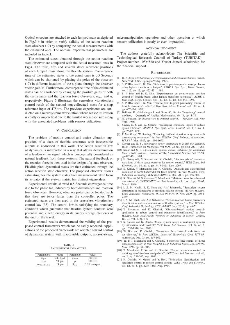
Optical encoders are attached to each lumped mass as depicted
in Fig.3-b in order to verify validity of the action reaction
state observer (17) by comparing the actual measurements with
the estimated ones. The nominal experimental parameters are
included in table.I.
The estimated states obtained through the action reaction
state observer are compared with the actual measured ones in
Fig.4. The third, fifth and seventh states represent positions
of each lumped mass along the flexible system. Convergence
time of the estimated states to the actual ones is 0.5 Seconds
which can be shortened by placing the poles of the observer
(17) in different locations of the s-plane through the observer
vector gain M. Furthermore, convergence time of the estimated
states can be shortened by changing the positive gains of both
the disturbance and the reaction force observers, gdist and g,
respectively. Figure 5 illustrates the sensorless vibrationless
control result of the second non-collocated mass for a step
reference input of 475µm. The previous experiments are con-
ducted on a microsystems workstation where sensor utilization
is costly or impractical due to the limited workspace size along
with the associated problems with sensors utilization.
V. CONCLUSION
The problem of motion control and active vibration sup-
pression of a class of flexible structures with inaccessible
outputs is addressed in this work. The action reaction law
of dynamics is interpreted in a way that allows determination
of a feedback-like signal which is conceptually considered as
natural feedback from these systems. The natural feedback or
the reaction force is then used in the design of a state observer.
Flexible plant dynamical states are then estimated through the
action reaction state observer. The proposed observer allows
estimating flexible system states from measurement taken from
its actuator if the system matrix has distinct eigenvalues.
Experimental results showed 0.5 Seconds convergence time
due to the phase lag induced by both disturbance and reaction
force observers. However, observer poles can be located such
that they are twice faster than the controller poles. The
estimated states are then used in the sensorless vibrationless
control law (33). The control law is satisfying the boundary
condition which guarantee that flexible system contains zero
potential and kinetic energy in its energy storage elements at
the end of the travel.
Experimental results demonstrated the validity of the pro-
posed control framework which can be easily repeated. Appli-
cations of the proposed framework are oriented toward control
of dynamical system with inaccessible outputs, microsystems,
TABLE IEXPERIMENTAL PARAMETERS.
Parameters Value Parameter Value
kfn 6.43 N/A gdist 100 Hzman 59 gm g 100 Hz
m1n,2n,3n 19 gm kbn 5.25 mv/rpm
micromanipulation operation and other operation at which
sensors utilization is costly or even impractical.
ACKNOWLEDGMENT
The authors gratefully acknowledge The Scientific and
Technological Research Council of Turkey (TUBITAK) -
Project number 108M520 and Yousef Jameel scholarship for
the financial support.
REFERENCES
[1] D. K .Miu, Mechatronics-electromechanics and contromechanics, 3rd ed.New York, USA: Springer-Verlag, 1993.
[2] S. P. Bhat and D. K. Miu, ”Solutions to point-to-point control problemsusing laplace transform technique”, ASME J. Dyn. Syst., Meas. Control,vol. 113, no. 13, pp. 425-431, 1991.
[3] S. P. Bhat and D. K. Miu, ”Experimentats on point-to-point positioncontrol of flexible beam using laplace transform technique”, ASME J.
Dyn. Syst., Meas. Control, vol. 113, no. 13, pp. 438-443, 1991.[4] S. P. Bhat and D. K. Miu, ”Precise point-to-point positioning control of
flexible structures”, ASME J. Dyn. Syst., Meas. Control, vol. 112, no. 4,pp. 667-674, 1990.
[5] Bellman, R., Glicksbergm I. and Gross. O, On the ’bang-bang’ control
problem, Quarterly of Applied Mathematics, Vol 14, pp.11-18.[6] G. Leitmann, An introduction to optimal control, McGraw-Hill, New
York, 1966.[7] Singer, N. C and W. Seering, ”Preshaping command inputs to reduce
systen vibration”, ASME J. Dyn. Syst., Meas. Control, vol. 112, no. 1,pp. 76-82, 1990.
[8] P. Meckl and W. Seering, ”Reducing residual vibration in systems withtime-varying resonances,” in Proc IEEEInt. Conf. Robotics, Automation,
ICRA’87, Mar. 1987, pp. 1690-1695.[9] Cooper and E. S , Minimizing power dissipation in a disk file actuator,
IEEE Transaction on Magnetics, Vol MAG-24-N3, pp.2081-2091, 1988.[10] Skaar and S. B, Closed form optimal control solutions for continuios
linear elastic systems, Journal of The Astronatical Science, Vol 32-N4,pp.447-461, 1984.
[11] H. Kobayashi, S. Katsura and K. Ohnishi, ”An analysis of parametervariations of disturbance observer for motion control,” IEEE Trans. Ind
Electron., vol. 54, no. 6, pp. 3413-3421, Dec. 2007.[12] S. Katsur, Y. Matsumoto and K. Ohnishi, ”Analysis and experimental
validation of force bandwidth for force control,” in Proc IEEEInt. Conf.
Industrial Technology, ICIT’03-MARIBOR, Dec. 2003, pp. 796-801.[13] K. Ohnishi, M. Shibata and T. Murakami, ”Motion control for advanced
mechatronics”, IEEE/ASME Trans. Mechatronics, vol. 1, no. 1, pp. 56-67,March. 1996.
[14] I. S. M. Khalil, E. D. Kunt and Asif Sabanovic, ”Sensorless torqueestimation in multidegree-of-freedom flexible system,” in Proc IEEEInt.
Conf. Industrial Technology, IECON’09-PORTO, Nov. 2009, pp. 2354-2359.
[15] I. S. M. Khalil and Asif Sabanovic, ”Action-reaction based parametersidentification and states estimation of flexible systems,” in Proc IEEEInt.
Conf. Industrial Technology, ISIE’10-PARI, July. 2010, pp. 46-51.[16] T. Murakami and K. Ohnishi, ”Observer-based motion control-
application to robust control and parameter identification,” in Proc
IEEEInt. Conf. Asia-Pacific Worshop on Advances in Motion Control,Jul. 93, vol. 1, pp. 1-6.
[17] S. Katsura and K. Ohishi, ”Modal system design of multirobot systemsby interaction mode control,” IEEE Trans. Ind Electron., vol. 54, no. 3,pp. 1537-1546, Jun. 2007.
[18] W. Iida and K. Ohnishi, ”Sensorless force control with force er-ror observer,” in Proc IEEEInt. Industrial Technology, Conf. ICIT’03-
MARIBOR, Dec. 03, pp. 157-162.[19] Yu. F, T. Murakami and K. Ohnishi, ”Sensorless force control of direct
drive manipulator,” in Proc IEEEInt. Conf. Industrial Technology, ISIE’92,May. 1992, pp. 311-315.
[20] T. Murakami, F. Yu and K. Ohnishi, ”Torque sensorless control inmultidegree-of-freedom manipulator,” IEEE Trans. Ind Electron., vol. 40,no. 2, pp. 259-265, Apr. 1993.
[21] K. Ohnishi, N. Matsui and Y. Hori, ”Estimation, identification, andsensorless control in motion control system,” IEEE Trans. Ind Electron.,vol. 82, no. 8, pp. 1253-1265, Aug. 1994.