Embed Size (px)
Citation preview

www.sensorlink.no www.sensorlink.no
Online and Real-Time Corrosion and Erosion
Monitoring of Subsea Pipework and Pipelines using Permanently Installed or Retrofitted
Ultrasonic Sensor Arrays
Edd Tveit Director Business Development [email protected]
Hanne Martinussen COO [email protected]

www.sensorlink.no www.sensorlink.no
Motivations and Applications
Pulse/Echo Ultrasonic Measurements
UT versus ring pair probe spools
Subsea configurations and communication options
Executed subsea projects
Future UT arrays
Outline
www.sensorlink.no www.sensorlink.no
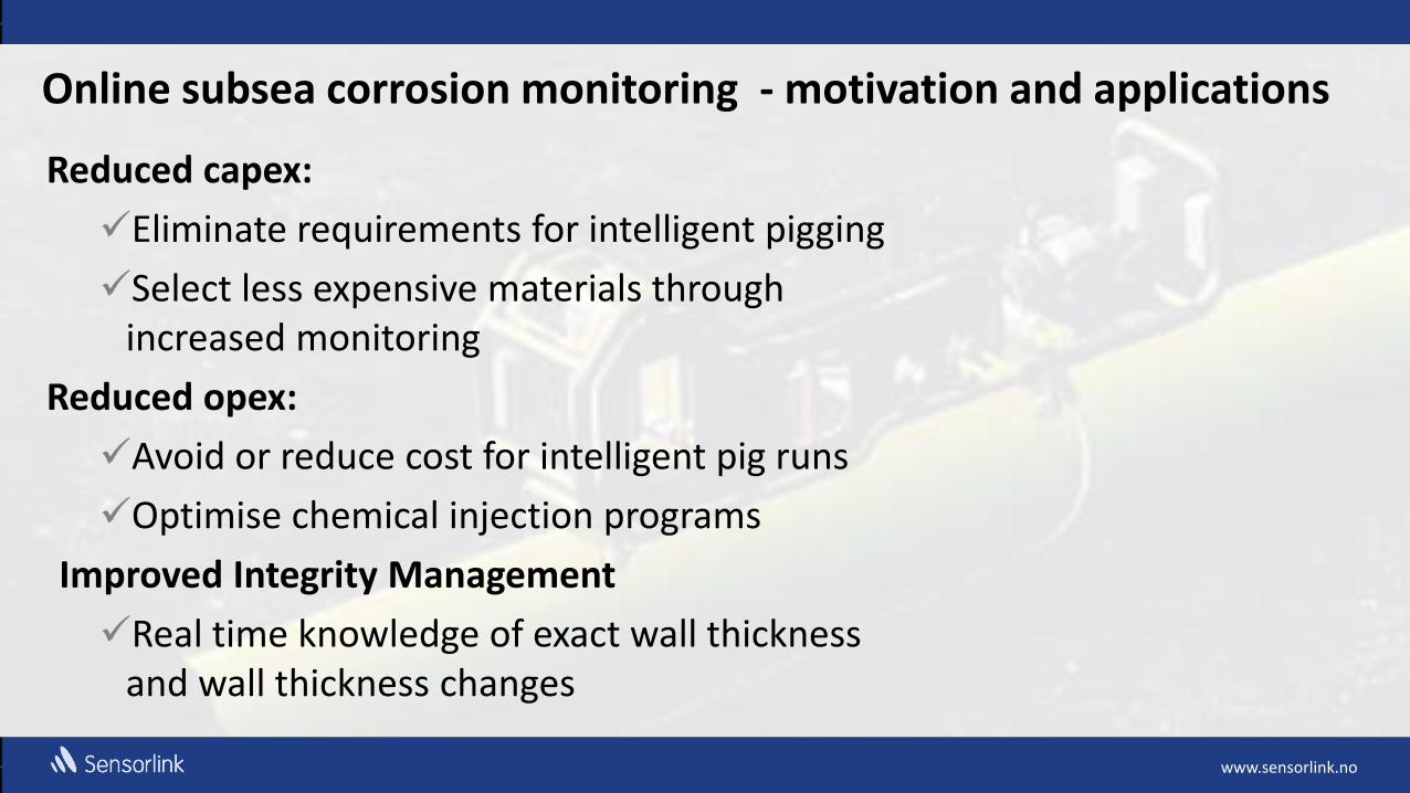
Online subsea corrosion monitoring - motivation and applications
Reduced capex:
Eliminate requirements for intelligent pigging
Select less expensive materials through increased monitoring
Reduced opex:
Avoid or reduce cost for intelligent pig runs
Optimise chemical injection programs
Improved Integrity Management
Real time knowledge of exact wall thickness and wall thickness changes
www.sensorlink.no www.sensorlink.no
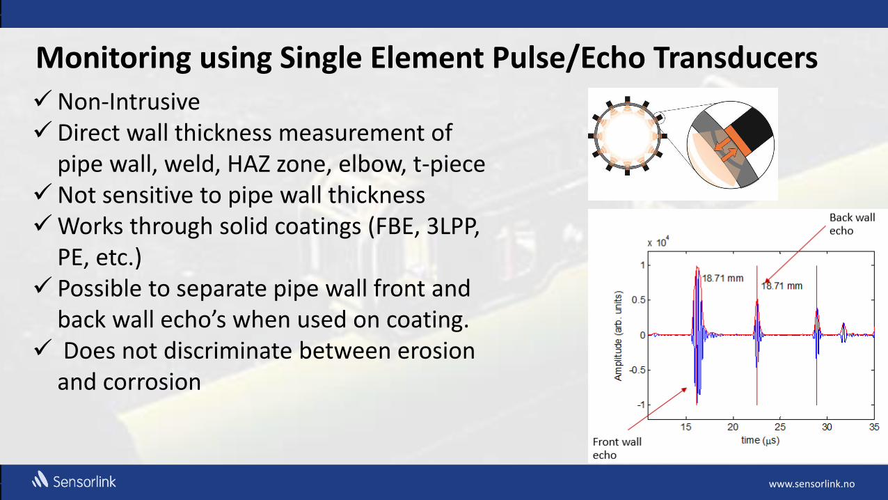
Monitoring using Single Element Pulse/Echo Transducers Non-Intrusive Direct wall thickness measurement of
pipe wall, weld, HAZ zone, elbow, t-piece Not sensitive to pipe wall thickness Works through solid coatings (FBE, 3LPP,
PE, etc.) Possible to separate pipe wall front and
back wall echo’s when used on coating. Does not discriminate between erosion
and corrosion

www.sensorlink.no www.sensorlink.no
No need for calibration: - speed of sound in steel is known - time of flight is measured using a crystal
Works with a “stand off” between the transducer and the pipe wall - not sensitive for installation on “out of roundness” pipelines
Fixed sensors combined with advanced signal processing detects wall loss of less than .1 mills (2.5 micrometres)
Free forming sensor matrix to suit corrosion/erosion phenomena
Pulse-echo:
𝑑 =𝑡 ∙ 𝑐
2
c – speed of sound in steel t – time d – wall thickness
Monitoring using Single Element Pulse/Echo Transducers

www.sensorlink.no
Pulse Echo UT array versus Ring Pair Probe Spools
Ethernet, OPC
Parameter UT Array Ring pair probes
Type of measurement Directly measurement of the pipe wall using pulse/echo UT
Indirect Electiral Restiance (Same as FSM) measurement on sample rings in the ring pair probe spool
Installation on new pipelines Preinstalled on standard pipe joint on top of a field weld. Truly none intrusive with no pipe wall penetration
Special pipejoint made sensing instrumentatioin inside pressure barrier with wall penetration to external electronics
Installation on existing pipework and pipelines
ROV or Diver deployable. Truly none intrusive with no pipe wall penetration
Not possible
Temperature sensitivy Moderate High
Concept for obtaining high resolution
High quality electronics and transducers and advanced signal processing
Use of thin ring-coupons (life time limits on coupons?)
Erosion versus corrsosion Does not descrimitate between erosion and corrsosion. Measures erosion on the pipeline itselves
Measures erosion in the ring pair probe spool
www.sensorlink.no
Ethernet, OPC
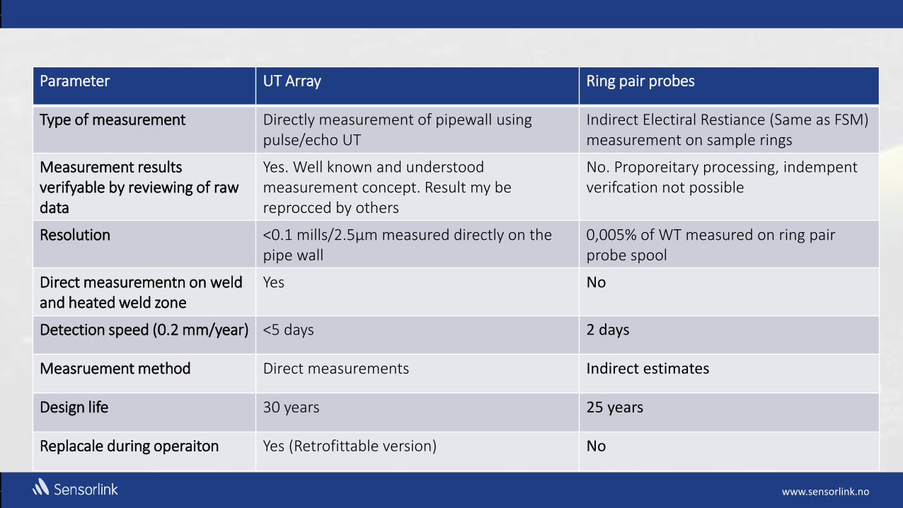
Parameter UT Array Ring pair probes
Type of measurement Directly measurement of pipewall using pulse/echo UT
Indirect Electiral Restiance (Same as FSM) measurement on sample rings
Measurement results verifyable by reviewing of raw data
Yes. Well known and understood measurement concept. Result my be reprocced by others
No. Proporeitary processing, indempent verifcation not possible
Resolution <0.1 mills/2.5µm measured directly on the pipe wall
0,005% of WT measured on ring pair probe spool
Direct measurementn on weld and heated weld zone
Yes No
Detection speed (0.2 mm/year) <5 days 2 days
Measruement method Direct measurements Indirect estimates
Design life 30 years 25 years
Replacale during operaiton Yes (Retrofittable version) No
www.sensorlink.no
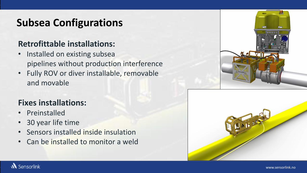
Subsea Configurations
Retrofittable installations: • Installed on existing subsea pipelines without production interference • Fully ROV or diver installable, removable and movable
Fixes installations: • Preinstalled • 30 year life time • Sensors installed inside insulation • Can be installed to monitor a weld

www.sensorlink.no
Specifications of Permanent Installed and retrofit subsea UT Arrays:
• Design temperature: -20 to 150°C • Design pressure exposed electronics: 300 bar (10000
feet) • Design pressure canister datalogger: 300 bar (10000
feet) • Design life permanent installations: 30 years • Design life retrofit installations: 15 years • Transducer density >30% • Resolution: <2.5 µm • Wall thickness: <200 mm
www.sensorlink.no
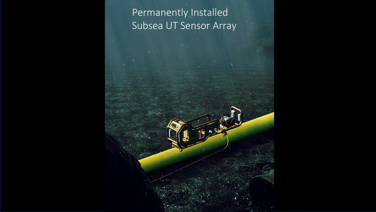
Permanently Installed Subsea UT Sensor Array

www.sensorlink.no
Layout of permanent UT Array
2
1
3
www.sensorlink.no
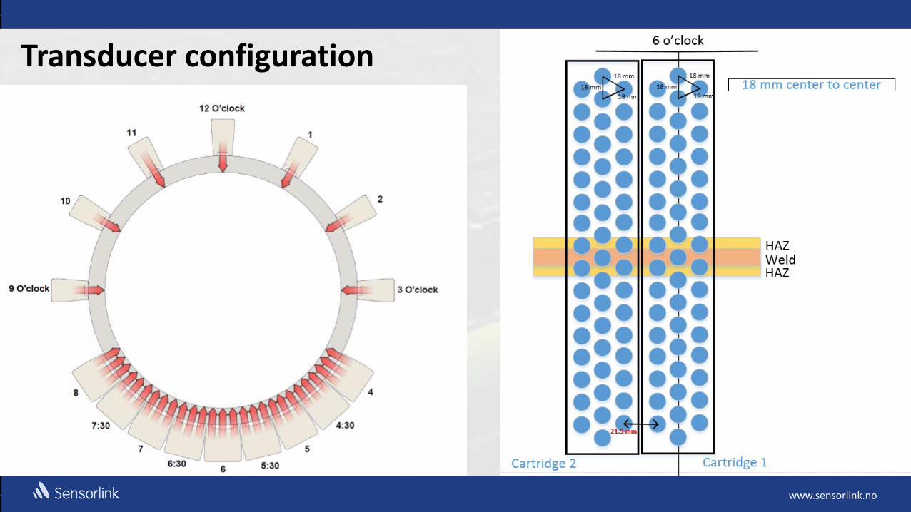
Transducer configuration

www.sensorlink.no
Wall thickness plot from one sensor

www.sensorlink.no

www.sensorlink.no
Ethernet Modbus TCP/IP Modbus RTU Canbus
Main control system
Network interface - Display Data
Subsea Signal Processing
Transfer of display data ~20 per unit, 1-6 times per day

www.sensorlink.no
Amount of dispaly/engineering data for communication
• 6 readings per day on a tool with 500 sensors • Local Data logger processess raw data and converts to wall thickness and
communicates results, inclusive one temperature reading per cassette and housekeeping data; ~ 24 kB per day, og 4 kB every 4 hours.
• Power consumption active < 10 W idle/sleep: <0.001w
www.sensorlink.no
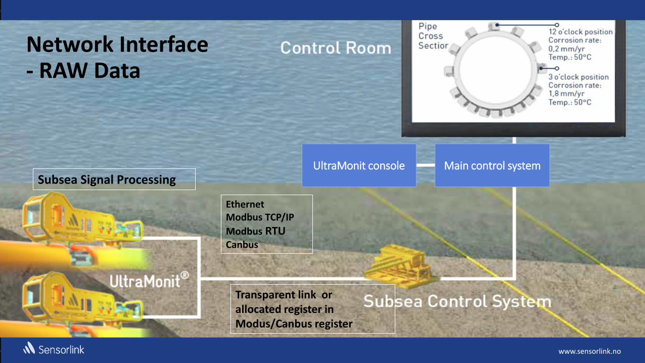
Ethernet Modbus TCP/IP
Modbus RTU Canbus
Main control system
Network Interface - RAW Data
Transparent link or allocated register in Modus/Canbus register
UltraMonit console Subsea Signal Processing

www.sensorlink.no
Amount of data communicated collecting raw data
• Raw data for 52 weekly readings for one cassette having 17 sensors equals about 3500 kB of data.
• Raw data is relevant for commissioning post processing for detailed corrosion analyzis
www.sensorlink.no
19
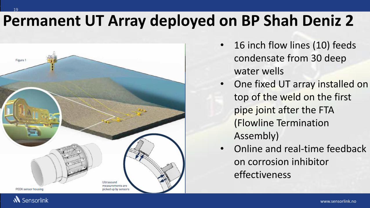
Permanent UT Array deployed on BP Shah Deniz 2
• 16 inch flow lines (10) feeds condensate from 30 deep water wells
• One fixed UT array installed on top of the weld on the first pipe joint after the FTA (Flowline Termination Assembly)
• Online and real-time feedback on corrosion inhibitor effectiveness

www.sensorlink.no
20
BP Shah Deniz In-Situ:
• Transducer array with 144 sensors covers straight pipe, field weld and HAZ zone.
• Real-time feed back on corrosion inhibitors effectiveness gives reduced opex cost
• The ability to rapidly detect corrosion rate changes enables the operator to plan and execute necessary actions to ensure that the corrosion rate do not exceed the maximum allowed rate (30 year design life time)
www.sensorlink.no
21
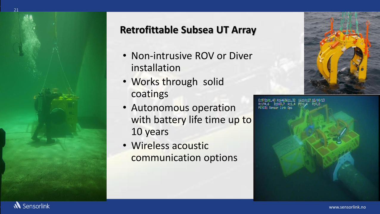
Retrofittable Subsea UT Array
• Non-intrusive ROV or Diver installation
• Works through solid coatings
• Autonomous operation with battery life time up to 10 years
• Wireless acoustic communication options

www.sensorlink.no
Data storage and collection – Battery Operation
Local data processing and storage Wall thickness data transfer via acoustic link 10 year battery life (@ 4 measurements per
day and 100 transducers) Consumption active: <10w, idle/sleep:
<0.001w
www.sensorlink.no
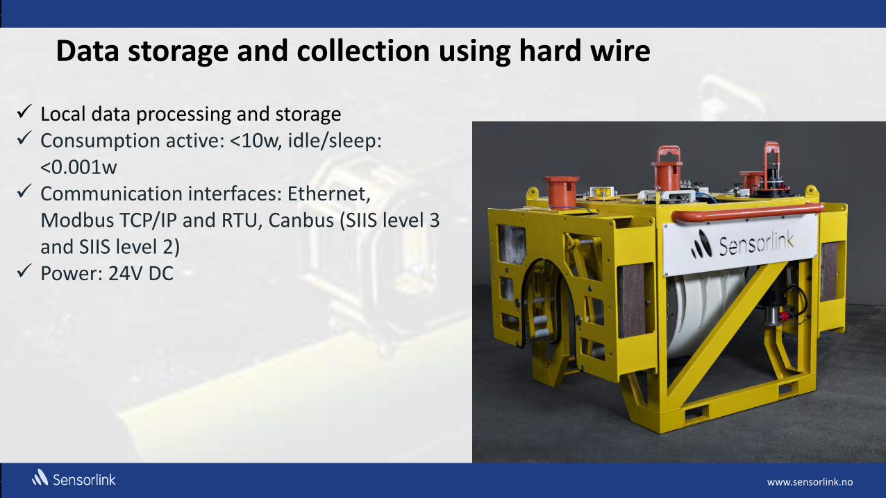
Data storage and collection using hard wire
Local data processing and storage Consumption active: <10w, idle/sleep:
<0.001w Communication interfaces: Ethernet,
Modbus TCP/IP and RTU, Canbus (SIIS level 3 and SIIS level 2)
Power: 24V DC

www.sensorlink.no
24
• Pigging showed local corrosion areas
• A 34” UltraMonit® subsea tool was installed to verify the chemical inhibition program
• Real time communication to the platform via radio link
• Data buoy with solar panels, batteries, data logger and radio link
• Anchor structure with subsea backup Data Logger
• Data showed little or no corrosion – inhibition successful
Retrofittable UT Array deployed on a 34 inch subsea crude oil pipeline
www.sensorlink.no
25
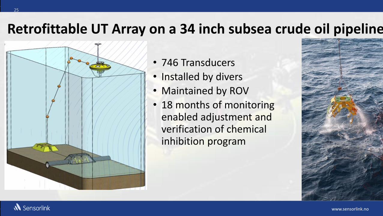
• 746 Transducers
• Installed by divers
• Maintained by ROV
• 18 months of monitoring enabled adjustment and verification of chemical inhibition program
Retrofittable UT Array on a 34 inch subsea crude oil pipeline

www.sensorlink.no www.sensorlink.no
ROV Deployable UT Sensor Arrays for Inspection

www.sensorlink.no www.sensorlink.no
UT Arrays for Subsea Pipeline Inspection
ROV deployable inspection tool providing autonomous scanning using an array of pulse/echo transducers operated by a battery driven data logger

www.sensorlink.no www.sensorlink.no
ROV flies in and mount an anchor frame. The anchor frame may be left in position to enable re-inspection of the same spot
ROV flies in the inspection unit. A green light will indicate completed inspection cycle
www.sensorlink.no www.sensorlink.no
Any Questions, please?

www.sensorlink.no www.sensorlink.no
Trondheim by night ©John Einar Sandvand
Thank You!