Embed Size (px)
Citation preview
ME 423: Machine DesignInstructor: Ramesh Singh
Sensors and Actuators:Servomotors and Servo Drives
Notes: From Omron Technical Guidehttp://www.ia.omron.com/support/guide/14/introduction.html
1
ME 423: Machine DesignInstructor: Ramesh Singh
Outline
• Servomotors and Servo Drive• Definition of key terms • Selection of Servomotors
2
ME 423: Machine DesignInstructor: Ramesh Singh
Servomotors & Servo Drive• A servomotor is a structural unit of a servo system and
is used with a servo drive• The servomotor includes :
– Motor that drives the load – Position detection component, such as an encoder.
• The servo system varies the controlled quantity, – Position, speed, or torque, according to the set target value
(command value) to precisely control the machine operation
3
ME 423: Machine DesignInstructor: Ramesh Singh
Servo System Configuration
4
SensorsSwitches
Safety Components
RelaysControl Com
ponentsAutom
ation Systems
Motion / DrivesEnergy Conservation Support / Environment Measure Equipment
Power Supplies /In Addition
OthersCom
mon
1
CSM_Servo_TG_E_1_1
Technical Explanation for Servomotors and Servo Drives
IntroductionWhat Is a Servomotor and What Is a Servo Drive?A servomotor is a structural unit of a servo system and is used with a servo drive. The servomotor includes the motor that drives the load and a position detection component, such as an encoder.The servo system vary the controlled amount, such as position, speed, or torque, according to the set target value (command value) to precisely control the machine operation.
Servo System Configuration Example
EncoderServomotor
Table
Ball screw
Servomotor
Power transmission mechanism
Servo drive
Feedback signalsFeedback signals
Motor power signalsTarget values
Controller
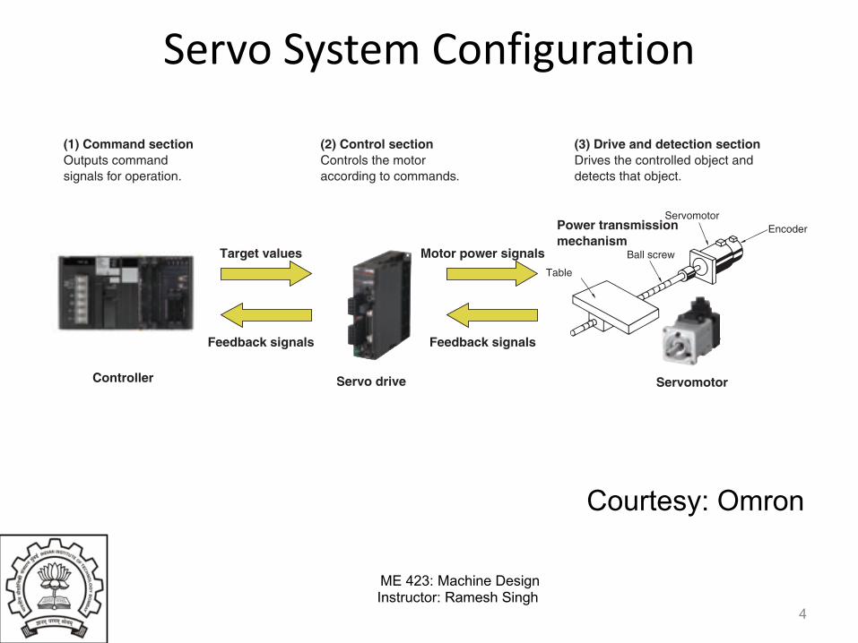
(1) Command section (2) Control sectionControls the motor according to commands.
Outputs command signals for operation.
(3) Drive and detection sectionDrives the controlled object and detects that object.
Courtesy: Omron

ME 423: Machine DesignInstructor: Ramesh Singh
Features of Servomotors• Precise, High-speed Control
– Servomotors excel at position and speed control– Precise and flexible positioning is possible– Servomotors do not stall even at high speeds– Deviations due to large external forces are corrected
because encoders are used to monitor movement.
5
ME 423: Machine DesignInstructor: Ramesh Singh
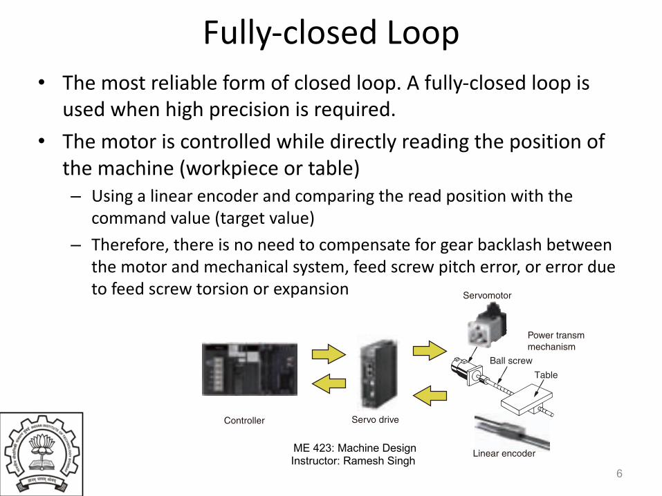
Fully-closed Loop• The most reliable form of closed loop. A fully-closed loop is
used when high precision is required.• The motor is controlled while directly reading the position of
the machine (workpiece or table)– Using a linear encoder and comparing the read position with the
command value (target value)– Therefore, there is no need to compensate for gear backlash between
the motor and mechanical system, feed screw pitch error, or error due to feed screw torsion or expansion
6
Technical Explanation for Servomotors and Servo Drives
2
SensorsSwitches
Safety Components
RelaysControl Com
ponentsAutom
ation Systems
Motion / DrivesEnergy Conservation Support / Environment Measure Equipment
Power Supplies /In Addition
OthersCom
mon
FeaturesPrecise, High-speed Control
Fully-closed LoopThe most reliable form of closed loop. A fully-closed loop is used when high precision is required.The motor is controlled while directly reading the position of the machine (workpiece or table) using a linear encoder and comparing the read position with the command value (target value). Therefore, there is no need to compensate for gear backlash between the motor and mechanical system, feed screw pitch error, or error due to feed screw torsion or expansion.
Fully-closed Loop System Configuration Example
Semi-closed LoopThis method is commonly used in servo systems.It is faster and has better positioning precision than an open loop.Typically an encoder or other detector is attached behind the motor. The encoder detects the rotation angle of a feed screw (ball screw) and provides it as feedback of the machine (workpiece or table) travel position. This means that the position of the machine is not detected directly.The characteristics depend on where the detector is installed.
Semi-closed Loop System Configuration Example
Open LoopA stepper motor is used instead of a servomotor. There is no feedback loop.The overall configuration is simple. Positioning can be performed at low cost, but gear and ball screw backlash and pitch errors cannot be compensated. When a stepper motor stalls, an error will occur between the command value and the actual movement. This error cannot be compensated.Open loop control is suitable for low-precision, low-cost, low-speed, and low-load-change applications.
Open Loop System Configuration Example
• Servomotors excel at position and speed control.• Precise and flexible positioning is possible.• Servomotors do not stall even at high speeds. Deviations due to large external forces are corrected because encoders are used
to monitor movement.
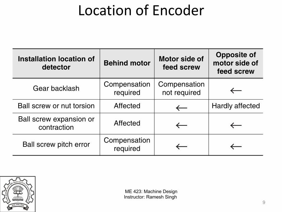
Installation location of detector Behind motor Motor side of
feed screw
Opposite of motor side of
feed screw
Gear backlash Compensation required
Compensation not required
Ball screw or nut torsion Affected Hardly affected
Ball screw expansion or contraction Affected
Ball screw pitch error Compensation required
Servomotor
Power transmissimechanism
Linear encoder
Servo driveController
Ball screw
Table
Table
Ball screw
Servomotor
Servo driveController
Stepper motor drive
Stepper motor
Controller
Table
Ball screw

ME 423: Machine DesignInstructor: Ramesh Singh
Open Loop• A stepper motor is used instead of a servomotor. There is no feedback
loop.• The overall configuration is simple. Positioning can be performed at low
cost, but gear and ball screw backlash and pitch errors cannot be compensated.
• When a stepper motor stalls, an error will occur between the command value and the actual movement. This error cannot be compensated.
• Open loop control is suitable for low-precision, low-cost, low- speed, and low-load-change applications.
7
Technical Explanation for Servomotors and Servo Drives
2
SensorsSwitches
Safety Components
RelaysControl Com
ponentsAutom
ation Systems
Motion / DrivesEnergy Conservation Support / Environment Measure Equipment
Power Supplies /In Addition
OthersCom
mon
FeaturesPrecise, High-speed Control
Fully-closed LoopThe most reliable form of closed loop. A fully-closed loop is used when high precision is required.The motor is controlled while directly reading the position of the machine (workpiece or table) using a linear encoder and comparing the read position with the command value (target value). Therefore, there is no need to compensate for gear backlash between the motor and mechanical system, feed screw pitch error, or error due to feed screw torsion or expansion.
Fully-closed Loop System Configuration Example
Semi-closed LoopThis method is commonly used in servo systems.It is faster and has better positioning precision than an open loop.Typically an encoder or other detector is attached behind the motor. The encoder detects the rotation angle of a feed screw (ball screw) and provides it as feedback of the machine (workpiece or table) travel position. This means that the position of the machine is not detected directly.The characteristics depend on where the detector is installed.
Semi-closed Loop System Configuration Example
Open LoopA stepper motor is used instead of a servomotor. There is no feedback loop.The overall configuration is simple. Positioning can be performed at low cost, but gear and ball screw backlash and pitch errors cannot be compensated. When a stepper motor stalls, an error will occur between the command value and the actual movement. This error cannot be compensated.Open loop control is suitable for low-precision, low-cost, low-speed, and low-load-change applications.
Open Loop System Configuration Example
• Servomotors excel at position and speed control.• Precise and flexible positioning is possible.• Servomotors do not stall even at high speeds. Deviations due to large external forces are corrected because encoders are used
to monitor movement.
Installation location of detector Behind motor Motor side of
feed screw
Opposite of motor side of
feed screw
Gear backlash Compensation required
Compensation not required
Ball screw or nut torsion Affected Hardly affected
Ball screw expansion or contraction Affected
Ball screw pitch error Compensation required
Servomotor
Power transmissimechanism
Linear encoder
Servo driveController
Ball screw
Table
Table
Ball screw
Servomotor
Servo driveController
Stepper motor drive
Stepper motor
Controller
Table
Ball screw

ME 423: Machine DesignInstructor: Ramesh Singh
Semi-closed Loop• This method is commonly used in servo systems.• It is faster and has better positioning precision than an open loop.• Typically an encoder or other detector is attached behind the motor. The
encoder detects the rotation angle of a feed screw (ball screw) and provides it as feedback of the machine (workpiece or table) travel position. This means that the position of the machine is not detected directly.
• The characteristics depend on where the detector is installed.
8
Technical Explanation for Servomotors and Servo Drives
2
SensorsSwitches
Safety Components
RelaysControl Com
ponentsAutom
ation Systems
Motion / DrivesEnergy Conservation Support / Environment Measure Equipment
Power Supplies /In Addition
OthersCom
mon
FeaturesPrecise, High-speed Control
Fully-closed LoopThe most reliable form of closed loop. A fully-closed loop is used when high precision is required.The motor is controlled while directly reading the position of the machine (workpiece or table) using a linear encoder and comparing the read position with the command value (target value). Therefore, there is no need to compensate for gear backlash between the motor and mechanical system, feed screw pitch error, or error due to feed screw torsion or expansion.
Fully-closed Loop System Configuration Example
Semi-closed LoopThis method is commonly used in servo systems.It is faster and has better positioning precision than an open loop.Typically an encoder or other detector is attached behind the motor. The encoder detects the rotation angle of a feed screw (ball screw) and provides it as feedback of the machine (workpiece or table) travel position. This means that the position of the machine is not detected directly.The characteristics depend on where the detector is installed.
Semi-closed Loop System Configuration Example
Open LoopA stepper motor is used instead of a servomotor. There is no feedback loop.The overall configuration is simple. Positioning can be performed at low cost, but gear and ball screw backlash and pitch errors cannot be compensated. When a stepper motor stalls, an error will occur between the command value and the actual movement. This error cannot be compensated.Open loop control is suitable for low-precision, low-cost, low-speed, and low-load-change applications.
Open Loop System Configuration Example
• Servomotors excel at position and speed control.• Precise and flexible positioning is possible.• Servomotors do not stall even at high speeds. Deviations due to large external forces are corrected because encoders are used
to monitor movement.
Installation location of detector Behind motor Motor side of
feed screw
Opposite of motor side of
feed screw
Gear backlash Compensation required
Compensation not required
Ball screw or nut torsion Affected Hardly affected
Ball screw expansion or contraction Affected
Ball screw pitch error Compensation required
Servomotor
Power transmissimechanism
Linear encoder
Servo driveController
Ball screw
Table
Table
Ball screw
Servomotor
Servo driveController
Stepper motor drive
Stepper motor
Controller
Table
Ball screw
ME 423: Machine DesignInstructor: Ramesh Singh
Location of Encoder
9
Technical Explanation for Servomotors and Servo Drives
2
SensorsSwitches
Safety Components
RelaysControl Com
ponentsAutom
ation Systems
Motion / DrivesEnergy Conservation Support / Environment Measure Equipment
Power Supplies /In Addition
OthersCom
mon
FeaturesPrecise, High-speed Control
Fully-closed LoopThe most reliable form of closed loop. A fully-closed loop is used when high precision is required.The motor is controlled while directly reading the position of the machine (workpiece or table) using a linear encoder and comparing the read position with the command value (target value). Therefore, there is no need to compensate for gear backlash between the motor and mechanical system, feed screw pitch error, or error due to feed screw torsion or expansion.
Fully-closed Loop System Configuration Example
Semi-closed LoopThis method is commonly used in servo systems.It is faster and has better positioning precision than an open loop.Typically an encoder or other detector is attached behind the motor. The encoder detects the rotation angle of a feed screw (ball screw) and provides it as feedback of the machine (workpiece or table) travel position. This means that the position of the machine is not detected directly.The characteristics depend on where the detector is installed.
Semi-closed Loop System Configuration Example
Open LoopA stepper motor is used instead of a servomotor. There is no feedback loop.The overall configuration is simple. Positioning can be performed at low cost, but gear and ball screw backlash and pitch errors cannot be compensated. When a stepper motor stalls, an error will occur between the command value and the actual movement. This error cannot be compensated.Open loop control is suitable for low-precision, low-cost, low-speed, and low-load-change applications.
Open Loop System Configuration Example
• Servomotors excel at position and speed control.• Precise and flexible positioning is possible.• Servomotors do not stall even at high speeds. Deviations due to large external forces are corrected because encoders are used
to monitor movement.
Installation location of detector Behind motor Motor side of
feed screw
Opposite of motor side of
feed screw
Gear backlash Compensation required
Compensation not required
Ball screw or nut torsion Affected Hardly affected
Ball screw expansion or contraction Affected
Ball screw pitch error Compensation required
Servomotor
Power transmissimechanism
Linear encoder
Servo driveController
Ball screw
Table
Table
Ball screw
Servomotor
Servo driveController
Stepper motor drive
Stepper motor
Controller
Table
Ball screw

ME 423: Machine DesignInstructor: Ramesh Singh
Servo Operation and Configuration
• Controls motor operation in closed loop• The actual position, speed, or torque of the
servomotor is fed back to compare to the command value and errors
• Then the servo drive corrects the operation of the servomotor in real time using this error
• This cycle of feedback, error detection, and correction is called closed-loop control.
10

ME 423: Machine DesignInstructor: Ramesh Singh
Servo Operation• The control loop is processed by either of servo drive
or motion controller, or both • The control loops for position, speed, and torque are
independently used to achieve the required operation. • Applications will not always require all three control
loops• In some applications, only the control loop for torque
control will be required. • In other applications, current and speed for speed
control are required• In some cases, three control loops for position control
are required.
11

ME 423: Machine DesignInstructor: Ramesh Singh
Principle
12
Technical Explanation for Servomotors and Servo Drives
3
SensorsSwitches
Safety Components
RelaysControl Com
ponentsAutom
ation Systems
Motion / DrivesEnergy Conservation Support / Environment Measure Equipment
Power Supplies /In Addition
OthersCom
mon
PrinciplesServo Operation and ConfigurationA system built with servo drives and servomotors controls motor operation in closed loop. The actual position, speed, or torque of the servomotor is fed back to compare to the command value and calculate the following errors between them. Then the servo drive corrects the operation of the servomotor in realtime using this error information to ensure that the system can achieve the required performance. This cycle of feedback, error detection, and correction is called closed-loop control.The control loop is processed by either of servo drive or motion controller, or both depending on the required control. The control loops for position, speed, and torque are independently used to achieve the required operation. Applications will not always require all three control loops. In some applications, only the control loop for torque control will be required. In other applications, current and speed for speed control are required, and in still other applications, three control loops for position control are required.
ServomotorThe most common types of industrial servomotors are those based on brushless motors. The rotor has a powerful permanent magnet. The stator is composed of multiple conductor coils, and the rotor spins when the coils are powered in the specified order. The movement of the rotor is determined by the stator’s frequency, phase, polarity, and current when the correct current is supplied to the stator coils at the appropriate time.
EncoderServomotors are different from typical motors in that they have encoders. This allows high-speed and high-precision control according to the given position and speed commands.Encoders are one of the hardware elements that form the core of a servo system, and they generate speed and position feedback. In many cases, the encoder is built into the servomotor or attached to the servomotor. In certain applications, the encoder is an independent unit that is installed away from the servomotor. When the encoder is installed in a remote location, it is used for related parameters in addition to for control of servomotor operation.Encoders are divided into two kinds.• Incremental encoders• Absolute encoders
Multi-turn absolute encoders are typically used for servomotors.Refer to the Technical Explanation for Rotary Encoders for more information on encoders.
Servo DriveServo drives follow commands from the host controller and control the output torque, rotation speed, or position of motors.The position, speed, or torque are controlled according to inputs from a motion controller, feedback encoder, and the servomotor itself, and the servo drive supplies the appropriate amounts of power to the servomotor at the appropriate times.
The basic operating principle is the same as for an inverter, in which the motor is operated by converting AC power to DC power to be a certain frequency.
A servo drive also has the following functions.• Communications with the motion controller• Encoder feedback reading and realtime closed-loop control
adjustment• I/O processing for safety components, mode inputs, and
operating status output signals
Speed controlControl section Oscillator
Error counter Motor
Encoder
Position controlPosition commandSpeed command
Position feedback
Speed feedback
Current feedback
Torque control
Position loop gain
Error/speed conversion
Frequency/speed conversion
Multiplication
Drive
Speed loop gain Speed loop integral time constant
Motor shaftCase
Encoder
Rotor Permanent magnet
Stator coils
Speed, position, or torque
Control circuits
PWM
Encoder
Motor
Smoothing circuit section
Inverter section
Converter section
Servo drive
Fixed frequency (50/60 Hz)
Required frequency (0 to 400 Hz)
ME 423: Machine DesignInstructor: Ramesh Singh
Servomotors• Servomotors based on brushless motors are most
common• The rotor has a powerful permanent magnet• The stator is composed of multiple conductor coils,
and the rotor spins when the coils are powered in the specified order.
• The movement of the rotor is determined by the stator’s frequency, phase, polarity, and current
13

ME 423: Machine DesignInstructor: Ramesh Singh
Servomotors
14
Technical Explanation for Servomotors and Servo Drives
3
SensorsSwitches
Safety Components
RelaysControl Com
ponentsAutom
ation Systems
Motion / DrivesEnergy Conservation Support / Environment Measure Equipment
Power Supplies /In Addition
OthersCom
mon
PrinciplesServo Operation and ConfigurationA system built with servo drives and servomotors controls motor operation in closed loop. The actual position, speed, or torque of the servomotor is fed back to compare to the command value and calculate the following errors between them. Then the servo drive corrects the operation of the servomotor in realtime using this error information to ensure that the system can achieve the required performance. This cycle of feedback, error detection, and correction is called closed-loop control.The control loop is processed by either of servo drive or motion controller, or both depending on the required control. The control loops for position, speed, and torque are independently used to achieve the required operation. Applications will not always require all three control loops. In some applications, only the control loop for torque control will be required. In other applications, current and speed for speed control are required, and in still other applications, three control loops for position control are required.
ServomotorThe most common types of industrial servomotors are those based on brushless motors. The rotor has a powerful permanent magnet. The stator is composed of multiple conductor coils, and the rotor spins when the coils are powered in the specified order. The movement of the rotor is determined by the stator’s frequency, phase, polarity, and current when the correct current is supplied to the stator coils at the appropriate time.
EncoderServomotors are different from typical motors in that they have encoders. This allows high-speed and high-precision control according to the given position and speed commands.Encoders are one of the hardware elements that form the core of a servo system, and they generate speed and position feedback. In many cases, the encoder is built into the servomotor or attached to the servomotor. In certain applications, the encoder is an independent unit that is installed away from the servomotor. When the encoder is installed in a remote location, it is used for related parameters in addition to for control of servomotor operation.Encoders are divided into two kinds.• Incremental encoders• Absolute encoders
Multi-turn absolute encoders are typically used for servomotors.Refer to the Technical Explanation for Rotary Encoders for more information on encoders.
Servo DriveServo drives follow commands from the host controller and control the output torque, rotation speed, or position of motors.The position, speed, or torque are controlled according to inputs from a motion controller, feedback encoder, and the servomotor itself, and the servo drive supplies the appropriate amounts of power to the servomotor at the appropriate times.
The basic operating principle is the same as for an inverter, in which the motor is operated by converting AC power to DC power to be a certain frequency.
A servo drive also has the following functions.• Communications with the motion controller• Encoder feedback reading and realtime closed-loop control
adjustment• I/O processing for safety components, mode inputs, and
operating status output signals
Speed controlControl section Oscillator
Error counter Motor
Encoder
Position controlPosition commandSpeed command
Position feedback
Speed feedback
Current feedback
Torque control
Position loop gain
Error/speed conversion
Frequency/speed conversion
Multiplication
Drive
Speed loop gain Speed loop integral time constant
Motor shaftCase
Encoder
Rotor Permanent magnet
Stator coils
Speed, position, or torque
Control circuits
PWM
Encoder
Motor
Smoothing circuit section
Inverter section
Converter section
Servo drive
Fixed frequency (50/60 Hz)
Required frequency (0 to 400 Hz)
ME 423: Machine DesignInstructor: Ramesh Singh
Encoders• Servomotors are different from typical motors in that they have
encoders. This allows high-speed and high-precision control according to the given position and speed commands
• Encoders are one of the hardware elements that form the core of a servo system, and they generate speed and position feedback.
• In many cases, the encoder is built into the servomotor or attached to the servomotor.
• In certain applications, the encoder is an independent unit that is installed away from the servomotor. When the encoder is installed in a remote location.
• Encoders are divided into two kinds:– Incremental encoders– Absolute encoders
• Multi-turn absolute encoders are typically used for servomotors
15

ME 423: Machine DesignInstructor: Ramesh Singh
Servo Drive• Servo drives follow commands from the host controller
and control the output torque, rotation speed, or position
• The position, speed, or torque are controlled according to inputs from a motion controller, feedback encoder, and the servomotor
• The servo drive supplies the appropriate amounts of power to the servomotor at the appropriate times.
• The basic operating principle is the same as for an inverter, in which the motor is operated by converting AC power to DC power to be a certain frequency
16

ME 423: Machine DesignInstructor: Ramesh Singh
Servo Drive
17
Technical Explanation for Servomotors and Servo Drives
3
SensorsSwitches
Safety Components
RelaysControl Com
ponentsAutom
ation Systems
Motion / DrivesEnergy Conservation Support / Environment Measure Equipment
Power Supplies /In Addition
OthersCom
mon
PrinciplesServo Operation and ConfigurationA system built with servo drives and servomotors controls motor operation in closed loop. The actual position, speed, or torque of the servomotor is fed back to compare to the command value and calculate the following errors between them. Then the servo drive corrects the operation of the servomotor in realtime using this error information to ensure that the system can achieve the required performance. This cycle of feedback, error detection, and correction is called closed-loop control.The control loop is processed by either of servo drive or motion controller, or both depending on the required control. The control loops for position, speed, and torque are independently used to achieve the required operation. Applications will not always require all three control loops. In some applications, only the control loop for torque control will be required. In other applications, current and speed for speed control are required, and in still other applications, three control loops for position control are required.
ServomotorThe most common types of industrial servomotors are those based on brushless motors. The rotor has a powerful permanent magnet. The stator is composed of multiple conductor coils, and the rotor spins when the coils are powered in the specified order. The movement of the rotor is determined by the stator’s frequency, phase, polarity, and current when the correct current is supplied to the stator coils at the appropriate time.
EncoderServomotors are different from typical motors in that they have encoders. This allows high-speed and high-precision control according to the given position and speed commands.Encoders are one of the hardware elements that form the core of a servo system, and they generate speed and position feedback. In many cases, the encoder is built into the servomotor or attached to the servomotor. In certain applications, the encoder is an independent unit that is installed away from the servomotor. When the encoder is installed in a remote location, it is used for related parameters in addition to for control of servomotor operation.Encoders are divided into two kinds.• Incremental encoders• Absolute encoders
Multi-turn absolute encoders are typically used for servomotors.Refer to the Technical Explanation for Rotary Encoders for more information on encoders.
Servo DriveServo drives follow commands from the host controller and control the output torque, rotation speed, or position of motors.The position, speed, or torque are controlled according to inputs from a motion controller, feedback encoder, and the servomotor itself, and the servo drive supplies the appropriate amounts of power to the servomotor at the appropriate times.
The basic operating principle is the same as for an inverter, in which the motor is operated by converting AC power to DC power to be a certain frequency.
A servo drive also has the following functions.• Communications with the motion controller• Encoder feedback reading and realtime closed-loop control
adjustment• I/O processing for safety components, mode inputs, and
operating status output signals
Speed controlControl section Oscillator
Error counter Motor
Encoder
Position controlPosition commandSpeed command
Position feedback
Speed feedback
Current feedback
Torque control
Position loop gain
Error/speed conversion
Frequency/speed conversion
Multiplication
Drive
Speed loop gain Speed loop integral time constant
Motor shaftCase
Encoder
Rotor Permanent magnet
Stator coils
Speed, position, or torque
Control circuits
PWM
Encoder
Motor
Smoothing circuit section
Inverter section
Converter section
Servo drive
Fixed frequency (50/60 Hz)
Required frequency (0 to 400 Hz)

ME 423: Machine DesignInstructor: Ramesh Singh
Functions of Servo Drive
• A servo drive also has the following functions. – Communications with the motion controller – Encoder feedback reading and realtime closed-
loop control adjustment – I/O processing for safety components, mode
inputs, and operating status output signals
18
ME 423: Machine DesignInstructor: Ramesh Singh
19
Technical Explanation for Servomotors and Servo Drives
9
SensorsSwitches
Safety Components
RelaysControl Com
ponentsAutom
ation Systems
Motion / DrivesEnergy Conservation Support / Environment Measure Equipment
Power Supplies /In Addition
OthersCom
mon
* When handling vertical loads and a load affected by the external torque, allow for about 30% of capacity.
Explanation References
• Calculate Regenerative Energy from the Torque of all the moving parts.
• Please see the user manual of each product for the details on calculation of the regenerative energy.
• Check if the the number of encoder pulses meets the system specified resolution.
• Accuracy of Positioning
• Check if the calculation meets the specifications of the temporarily selected motor.If not, change the temporarily selected motor and re-calculate it.
• The following table
2
NO
Is the ResolutionOK?
YES
END Selection
Calculate Regenerative Energy
1
YES
NO
Are the Check Items on Characteristics
All OK?
Specialized Check Items
Check Items
Load Inertia Load Inertia ! Motor Rotor Inertia x Applicable Inertia Ratio
Effective TorqueEffective Torque < Motor Rated Torque• Please allow a margin of about 20%. *
Maximum Momentary Torque
Maximum Momentary Torque < Motor Maximum Momentary Torque• Please allow a margin of about 20%. *• For the motor Maximum Momentary Torque, use the value
that is combined with a driver and the one of the motor itself.
Maximum Rotation Speed
Maximum Rotation Speed ! Rated Rotation Speed of a motor• Try to get as close to the motor's rated rotations as possible.
It will increase the operating efficiency of a motor.• For the formula, please see "Straight-line Speed and Motor
Rotation Speed" on Page 16.
Regenerative Energy
Regenerative Energy ! Regenerative Energy Absorption of a motor• When the Regenerative Energy is large, connect a
Regenerative Energy Absorption Resistance to increase the Absorption capacity of the driver.
Encoder ResolutionEnsure that the Encoder Resolution meets the system specifications.
Characteristics of a Positioner
Check if the Pulse Frequency does not exceed the Maximum Response Frequency or Maximum Command Frequency of a Positioner.
Operating ConditionsEnsure that values of the ambient operating temperature/humidity, operating atmosphere, shock and vibrations meet the product specifications.
Technical Explanation for Servomotors and Servo Drives
8
SensorsSwitches
Safety Components
RelaysControl Com
ponentsAutom
ation Systems
Motion / DrivesEnergy Conservation Support / Environment Measure Equipment
Power Supplies /In Addition
OthersCom
mon
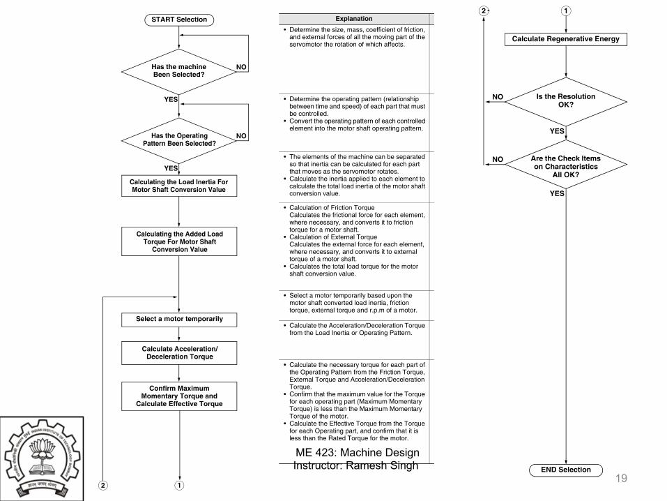
Further InformationServomotor Selection Flow Chart
Explanation References
• Determine the size, mass, coefficient of friction, and external forces of all the moving part of the servomotor the rotation of which affects.
---
• Determine the operating pattern (relationship between time and speed) of each part that must be controlled.
• Convert the operating pattern of each controlled element into the motor shaft operating pattern.
• Operation Pattern Formula
• The elements of the machine can be separated so that inertia can be calculated for each part that moves as the servomotor rotates.
• Calculate the inertia applied to each element to calculate the total load inertia of the motor shaft conversion value.
• Inertia Formulas
• Calculation of Friction TorqueCalculates the frictional force for each element, where necessary, and converts it to friction torque for a motor shaft.
• Calculation of External TorqueCalculates the external force for each element, where necessary, and converts it to external torque of a motor shaft.
• Calculates the total load torque for the motor shaft conversion value.
• Load Torque Formulas
• Select a motor temporarily based upon the motor shaft converted load inertia, friction torque, external torque and r.p.m of a motor.
---
• Calculate the Acceleration/Deceleration Torque from the Load Inertia or Operating Pattern.
• Acceleration/Deceleration Torque Formulas
• Calculate the necessary torque for each part of the Operating Pattern from the Friction Torque, External Torque and Acceleration/Deceleration Torque.
• Confirm that the maximum value for the Torque for each operating part (Maximum Momentary Torque) is less than the Maximum Momentary Torque of the motor.
• Calculate the Effective Torque from the Torque for each Operating part, and confirm that it is less than the Rated Torque for the motor.
• Calculation of Maximum Momentary Torque, Effective Torque
Has the Operating Pattern Been Selected?
NO
YES
START Selection
Has the machineBeen Selected?
NO
YES
Calculating the Load Inertia For Motor Shaft Conversion Value
Calculating the Added Load Torque For Motor Shaft
Conversion Value
Select a motor temporarily
Calculate Acceleration/Deceleration Torque
Confirm Maximum Momentary Torque and
Calculate Effective Torque
12
Technical Explanation for Servomotors and Servo Drives
8
SensorsSwitches
Safety Components
RelaysControl Com
ponentsAutom
ation Systems
Motion / DrivesEnergy Conservation Support / Environment Measure Equipment
Power Supplies /In Addition
OthersCom
mon
Further InformationServomotor Selection Flow Chart
Explanation References
• Determine the size, mass, coefficient of friction, and external forces of all the moving part of the servomotor the rotation of which affects.
---
• Determine the operating pattern (relationship between time and speed) of each part that must be controlled.
• Convert the operating pattern of each controlled element into the motor shaft operating pattern.
• Operation Pattern Formula
• The elements of the machine can be separated so that inertia can be calculated for each part that moves as the servomotor rotates.
• Calculate the inertia applied to each element to calculate the total load inertia of the motor shaft conversion value.
• Inertia Formulas
• Calculation of Friction TorqueCalculates the frictional force for each element, where necessary, and converts it to friction torque for a motor shaft.
• Calculation of External TorqueCalculates the external force for each element, where necessary, and converts it to external torque of a motor shaft.
• Calculates the total load torque for the motor shaft conversion value.
• Load Torque Formulas
• Select a motor temporarily based upon the motor shaft converted load inertia, friction torque, external torque and r.p.m of a motor.
---
• Calculate the Acceleration/Deceleration Torque from the Load Inertia or Operating Pattern.
• Acceleration/Deceleration Torque Formulas
• Calculate the necessary torque for each part of the Operating Pattern from the Friction Torque, External Torque and Acceleration/Deceleration Torque.
• Confirm that the maximum value for the Torque for each operating part (Maximum Momentary Torque) is less than the Maximum Momentary Torque of the motor.
• Calculate the Effective Torque from the Torque for each Operating part, and confirm that it is less than the Rated Torque for the motor.
• Calculation of Maximum Momentary Torque, Effective Torque
Has the Operating Pattern Been Selected?
NO
YES
START Selection
Has the machineBeen Selected?
NO
YES
Calculating the Load Inertia For Motor Shaft Conversion Value
Calculating the Added Load Torque For Motor Shaft
Conversion Value
Select a motor temporarily
Calculate Acceleration/Deceleration Torque
Confirm Maximum Momentary Torque and
Calculate Effective Torque
12

ME 423: Machine DesignInstructor: Ramesh Singh
Operating Patterns: Triangular
20
Technical Explanation for Servomotors and Servo Drives
10
SensorsSwitches
Safety Components
RelaysControl Com
ponentsAutom
ation Systems
Motion / DrivesEnergy Conservation Support / Environment Measure Equipment
Power Supplies /In Addition
OthersCom
mon
FormulasFormulas for Operating Patterns
Triangular
Maximum Speed
Acceleration/Deceleration Time
Travel Distance
Trapezoid
Maximum Speed
Acceleration/Deceleration Time
Total Travel Time
Constant-velocity travel time
Total Travel Distance
Acceleration/Deceleration Travel Distance
Constant-velocity travel distance
Speed and Slope When Ascending
Ascending Time
Ascending Time (tA) including distance moved
Speed after Ascending
Time
Speed
tA tA
t0
X0
v0X0: Distance Moved in t0 Time [mm]
v0: Maximum Speed [mm/s]
v0 =X0
tA
t0: Positioning Time [s]
tA: Acceleration/ Deceleration Time [s]
tA =X0
v0
X0 = v0·tA
TimetA tB
t0
tA
XA XB
X0
XA
v0
Speed v0 =X0
t0 – tA
tA = t0 – X0
v0
t0 = tA +X0
v0
X0
v0tB = t0 – 2·tA = 2·X0
v0 – t0 = – tA
X0 = v0 (t0 – tA)
XA = v0·tA2
v0·t0 – X0
2=
XB = v0·tB = 2·X0 – v0·t0
Timetg tA
v0
v1
vg
Speed Gradientvg
tg
Speed
tA = v0 – v1
Į
XA = 12 Į·tA2
+ v1·tA
12XA = (v0 – v1)
2
Į +v1·tA
v0 = v1+Į·tA

ME 423: Machine DesignInstructor: Ramesh Singh
Operating Patterns: Trapezoidal
21
Technical Explanation for Servomotors and Servo Drives
10
SensorsSwitches
Safety Components
RelaysControl Com
ponentsAutom
ation Systems
Motion / DrivesEnergy Conservation Support / Environment Measure Equipment
Power Supplies /In Addition
OthersCom
mon
FormulasFormulas for Operating Patterns
Triangular
Maximum Speed
Acceleration/Deceleration Time
Travel Distance
Trapezoid
Maximum Speed
Acceleration/Deceleration Time
Total Travel Time
Constant-velocity travel time
Total Travel Distance
Acceleration/Deceleration Travel Distance
Constant-velocity travel distance
Speed and Slope When Ascending
Ascending Time
Ascending Time (tA) including distance moved
Speed after Ascending
Time
Speed
tA tA
t0
X0
v0X0: Distance Moved in t0 Time [mm]
v0: Maximum Speed [mm/s]
v0 =X0
tA
t0: Positioning Time [s]
tA: Acceleration/ Deceleration Time [s]
tA =X0
v0
X0 = v0·tA
TimetA tB
t0
tA
XA XB
X0
XA
v0
Speed v0 =X0
t0 – tA
tA = t0 – X0
v0
t0 = tA +X0
v0
X0
v0tB = t0 – 2·tA = 2·X0
v0 – t0 = – tA
X0 = v0 (t0 – tA)
XA = v0·tA2
v0·t0 – X0
2=
XB = v0·tB = 2·X0 – v0·t0
Timetg tA
v0
v1
vg
Speed Gradientvg
tg
Speed
tA = v0 – v1
Į
XA = 12 Į·tA2
+ v1·tA
12XA = (v0 – v1)
2
Į +v1·tA
v0 = v1+Į·tA