Embed Size (px)
Citation preview
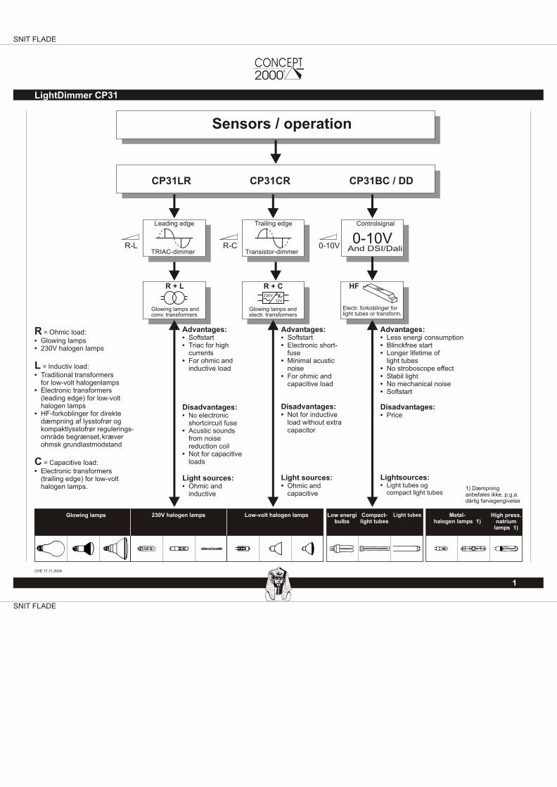
Sensors / operation
Glowing lamps 230V halogen lamps Low-volt halogen lamps Low energibulbs
Compact-light tubes
Light tubes Metal-halogen lamps 1)
High press.natrium
lamps 1)
R = Ohmic load:• Glowing lamps• 230V halogen lamps
L = Inductiv load:• Traditional transformers
for low-volt halogenlamps• Electronic transformers
(leading edge) for low-volthalogen lamps
• HF-forkoblinger for direkte dæmpning af lysstofrør og kompaktlysstofrør regulerings-
område begrænset,kræver ohmsk grundlastmodstand
C = Capacitive load:• Electronic transformers
(trailing edge) for low-volthalogen lamps.
Advantages:• Softstart• Electronic short-
fuse• Minimal acustic
noise• For ohmic and
capacitive load
Disadvantages:• Not for inductive
load without extracapacitor
Light sources:• Ohmic and
capacitive
Advantages:• Less energi consumption• Blinckfree start• Longer lifetime of
light tubes• No stroboscope effect• Stabil light• No mechanical noise• Softstart
Disadvantages:• Price
Lightsources:• Light tubes og
compact light tubes1) Dæmpning anbefales ikke, p.g.a. dårlig farvegengivelse
Advantages:
• Triac for highcurrents
• For ohmic andinductive load
• Softstart
Disadvantages:• No electronic
shortcircuit fuse• Acustic sounds
from noisereduction coil
• Not for capacitiveloads
Light sources:• Ohmic and
inductive
R + L
Glowing lamps and conv. transformers
TRIAC-dimmer
Leading edge
230V
12V
R + C
Glowing lamps andelectr. transformers
Transistor-dimmer
Trailing edge
0-10V
HF
Electr. forkoblinger forlight tubes or transform.
Controlsignal
CP31LR CP31CR CP31BC / DD
0-10VR-L R-C
CHE 17.11.2004
11
And DSI/Dali
SNIT FLADE
SNIT FLADE
LightDimmer CP31

2.03Side
blblbllbblblbllblbllb
LightDimmer CP31LR and CP31CR
Leading edge CP31LR EAN-Nr. 5703513005757
Trailing edge CP31CREAN-Nr. 5703513005917
Load controller CP31BC EAN-Nr. 5703513006143
Product descriptionCP31xx is an intelligent programmable light dimmer unit available in 3 versions:- CP31LR for dimming of 40-1000 VA ohmic and
inductive load.- CP31CR for dimming of 40-600 VA ohmic and
capacitive load.- CP31BC for dimming of HF-loads for
light tubes using 0-10V control signals.CP31xx regulates logaritmically and has built-in softstart, termical fuse and null-wire failure detection. In addition CP31CR has a electronicshort fuse. The lightdimmer is controlled by a switch connected to input G offering: ON, OFF, UP and DOWN.Operation over the databus controls up to 40 built-in functions, as for example: All Off, All On, Group Off, Group On (fixed light level), light scenes, Sleep timer, etc. Parallel operation via databus allows control of multiple CP31's.Programming of functions is carried out with CONKEY CP79 or a PC.CP31 holds a 75 ma indicator output reflecting whether module is On or Off.
Technical data CP31xx:
High voltage:CP31LRLoad 220V AC/50Hz 40-1000 VA
Load 110V AC/60Hz * 40-500 VAPower loss < 1%CP31CRLoad 220V AC/50Hz 40-600 VA
Load 110V AC60Hz * 40-300 VAPower loss < 1%Low current CP31LR og CP31CR:Curr. consumption @ 18 V DC max. 30 mAPower consumption @ 18 V DC max. 0,5 VACommon data for CP31xx:Mains 230V AC/50 HzSoftstart 500 msdiscontinuation time <300 msFuse (type B) max.10 AIndications output max. 75 mACurr. consumption switch 0.5 mAImpulse time for switch 50-300 msCable dimension low current f.ex 0.6 mmCable length pr. input R max. 1 K-ohm
* Special version
4 6 8 10
C D E F G H I K LB
Modul nr.
+ _
Concept 2000
L N
ON
ELECTRONIC DIMMER TYPE CP 31
Connections for CP31LR/CR:
High voltage SymbolPin 4 L Phase inputPin 6 N NullPin 8 Regulated phasePin 10 Ground
Low voltage for CP31LR/CR/BCPin B + Plus 24V DCPin C - Minus (-)Pin D-E-F See page 5.29Pin G Impulse input (-)Pin H indicator output (-)Pin I I PIR/potentiometerPin K K DaylightsensorPin L L Conversation
Connecting CP31LR, CP31CR and CP31BC
Plus 24VMinus (-)Data
L N
Modul-Nr.
......
+ _
D
+ _
D
+ _
NL4 6 8 10
B C D E F G H I K L
24V
PE
Plus 24VMinus (-)Data
CP 31LR/CR
On/OffDimmer CP73
230V~50Hz
1 12
2 3
3 + -
ut
A
tP
o CP75HCP46H
NC
Note: PIR andpotentiometer cannotwork together
10AType B
Lightdimmer (Type G - GLC)
Plus 24VMinus (-)Data
12
3
Modul-Nr.
......
+ _
D
+ _
D
+ _
CP 31BC42 6 8 10 12
B C D E
LNO+
0-10+
10-0-
N
F G H I K L
24V
LN
+-1-10V
230V~
Electronic load
Plus 24VMinus (-)Data
*
**
TCA-print
24V 1 2 3 4
17 VAC
F 1,25A
L
P ***
230V~50Hz
On/OffDimmer
1
2
3 + -
ut
A
tP
o
NC
10AType B
L N
CP75HCP73CP46H
Technical data for CP31BC
High voltageMains max. 230V AC/50 HzRelay output 10A/230V ~ Load ohmic - cos phi=1,0 2300 VALoad inductive - cos phi=0,5 1150 VAIn- and out time max. 50 msFuse max. 10 ALoad 0-10V output max. 75 mALoad 10-0V output max. 5 mA
Low voltage for CP31 BCCurr. consumption @ 18 V DC max. 50 mAPower consumption @ 18 V DC max. 0,9 VA
* Note ! When programming min/maxlight levels, the short cut is fitted and thenremoved when programming is done.
** At higher loads or at 3-phase controluse a contactor with an RC across coil.
*** After applying high current and control-wires, the potentiometer "P" must beregulated. Turn off CP31BC and thatlightdimmer type G eller GLC are off.If light is not off the potentiometer "P" isturned clockwise untill light turns off.
Connections for CP31BC
High voltage SymbolPin 2 NO Relay output 10APin 4 L Phase inputPin 6 N NullPin 8 0-10V Output 0-10VPin 10 Minus (-)Pin 12 10-0V Output 10-0V
Note: PIR andpotentiometer cannotwork together
CHE 17.11.2004
22
SNIT FLADE
SNIT FLADE
LightDimmer CP31

Aemployment examples/ energy saving
The curve shows how many hours it is possible to save on artificial light. Pay only for the necessary light quantity.The sun is a great light source, which varies over the day, it makes a 180 degrees journey and has different attitude depending on the season. Therefore , you have to make demands on method of control and sensorss as well as their position. CP31XX is fit with an entry point for a daylight sensor in such a way that you can control the light during the daytime.
General - need - economyWithout doubt, there is economy in light controlling and light dimming. How much depends on the individual installation. We have seen payback times from six to four years but it completely depends on the arrangement of the room and its condition. Contact your electrician and remember that you get ‘light’ experiences when using less energy. Put a damper on the electricity bill.
Create the right atmosphere with light scenesA single push on the button can create the right lighting.For instance, you can have buttons for:Daily - The luminous, whitch you prefewhen entering the room.Guests - Dim light different levels - more light over the dinner table.Comfortable-Dim light where a few things are in focus.TV - Blinds are closed and the light is being dimmee in order not to daze.Cleaning -100% light
Daylight controlling.
Life time of incandescent lampsAs it is seen from this graph, it pays to dim the light. If the nominal mains voltage is lowered by 5 to 10%, most light sources average life time will double immediately. Tis reduction also results in less heat emission reducing the demand for air condition.
CP31xx regulates the artificial light as to much daylight there is. (The daylight sensor must “see”
50% daylight and 50% artificial light).The goldsmith wishes a lot of light during the day and a more dimmed lighting in the evening in his show window. This kind of lighting optimizes the customers' perception of a display.Day lighting and evening lighting at a service station make a demand for accommodation to daylight aiming at creating as little contrast between inside and outside. This happens by means of reverse day lighting. (Daylight sensor shall only “see” daylight)
The preferred
light quantity
Sky
sun-light
Morning
Artificial light=electricity paid for
Free daylight = electricity saved
Pay only for the necessary light quantity
Noon Evening
400
t (%)m
U (%)n
200
90 95 100 105 110
100
50
25
Averagelifetime
A*
Moduleroom nr. 2
Moduleroom nr. 1
** **
Connecting dimmers and ballast controllerConson has developed dimmer and ballast controllers in such a way that up to 10 dimmers/ballast controllers can controlled together. This function may be applied seveal plases.
For instance:Large rooms which by means of folding doors can be divided up into smaller rooms. In rooms or halls in which the load is too great for one dimmer/ballast controller the load can be divided between several dimmer in such a way that these may be connected permanently by connecting the “L’’ Clamps.
NB ! The connection of dimmers/ballast controllers must only be done at the side with low current. The regulating phases or outputs MUST NOT be connected.
DinnerTable
Lysscene 1RELAX
Lysscene 2GUESTS
Lysscene 3TV
Lysscene 4CLEANING
ALL OFF
ON/OFF
DAYLI
CoffeeTable
Wall Ceiling
20%
0% 0% 0%
70%50% 50%
10%
40%20% 40%
0%
50% 80% 60% 40%
10%40% 30% 40%
100% 100% 100% 100%
LL
CHE 17.11.2004
33
SNIT FLADE
SNIT FLADE
LightDimmer CP31

* Auxiliary relay function is employed with special functions for instance Group Turn on/off (see CP20), twilight relay (see CP70D).
** With ‘L’ communication (meaning no short between clamps ‘E’ and ‘L’) “toggle /M1” functions as Turn on/off, “light up” as Turn on and “light down” as Turn off.
Employment The following description of our intelligent dimmer module CP31xx only gives a small insight into the many possibilities offered by these dimmers. Compared to other dimmers at the market Conson set the standardDimmers module Cp31xx - Three different hardware versions:- CP31LR for ohmic and inductive load- CP31CR for ohmic and capacitive load- CP31BC for 0-10 / 10-0 volt's control- CP31DD for digital protocolAdvantages of dimmer modules CP31xx:-Short-circuit fuse (version CR)-Overload protection (Long useful life)-No fuse to be changed-10 light levels – different luminous intensities-Timer function – sleep function-Touch-control – on/off, up/down-Indication – for lay-out panel/buttons-Battery backup – for the next 1000 years-Advanced automatic control – simple regulation-Soft start with high starting current-Thermal protection with too high temperatures-Both dimmers and ballast controllers can be connected in a simple way-Logarithmic dimming with a single touch -Protection against zero disconnection-Fade times
“Sleep timer”: For instance, one push at the ‘sleep timer’ button turns on the light at 30-50% light and automatically turns of the light after 30 minutes when the children has fallen to sleep.“Sleep control”: One push at the ‘sleep control’ button turns on the light at for instance 10% light and automatically turns of the light after 15 seconds.“Everyday light”: Comfortable and energy-saving light in the house.“Guests”: The right and predetermined luminous intensity in the whole house when the guests arrive. Not only does the table have to look nice and food taste good, candle lights and artificial light including the lamps outside have to create the right atmosphere.“TV”: A clear pictures with a non-dazzling light – and with the curtains drawn.“Comfortable”: Feeling pleasant and comfortable make a demand for the right light
atmosphere.“Cleaning”: A must which demands 100% light.“Up at night”: The button next to the bed – some might call it a luxury but still very pleasant. A single push and the light is turned on at 10% in the bedroom, 50% in the hallway and 90% in the bathroom. When go back to bed, the light will automatically be turn off.“Getting home”: Just push one button and turn on the light you need when you get home.“Going to bed”: The button is placed next to the bed and turn off all the light in the house except the light in the bedroom.“Party”: Evocative light when you are having a party. At the same time, you can block the buttons all over the house in order to avoid anyone fiddling with the buttons.“Outside lightning”: Normally, you would turn on the outside lightning at a 100% when it gets dark outside. With Conson’s intelligent dimmers you can control the light at different luminous intensities depending on whether a person is outside or not.Example: When it gets dark, from 4 pm to 8 pm, the light turns on at 70% and from 8 pm to midnight, the luminous intensity is 30%. If a person walks by, the light will automatically increase to 100% in five minutes.“Imitated activity”: (Protection against burglars) Now, it is possible to turn on various lamps at different intensities which is suited to your needs.“Delayed turn off”: If you have a centrally placed lay-out panel or a ‘turn off everything’ button you will be able to make a delay (turn off >60 seconds). You will then have 60 seconds to get to the door before the light turns off.“Memory”: (Turn on, turn on in ? time and change-over) The dimmer turns on at the level last used. If the M1 (change-over) button has not been activated within 20 seconds the next function is to adjust the light up (a long push).
*
**
**
**
Control possibilities of the dimmer module Cp31 via the data bus:
Aktion via CP-Bus LCD-Display ON ON OFF Sluk Pulse (on/off,dim) Pulse ON for 15 seconds ON 15 s 30 30 s 45 45 s 1 1 m 5 5 m 10 10 m 15 15 m 20 20 m 30 30 m 45 45 m
60 60 m OFF after 15 OFF > 15 s 30 > 30 s 60 > 60 s 5 > 5 m 15 > 15 m 30 > 30 m 60 > 60 m Blocking (Bus+kipindgang) Block Auxiliary relay function Aux Light level up Light up Light level down Light down Light level 10% Light 10%
ON for seconds ONON for seconds ONON for Minutes ONON for Minutes ONON for Minutes ONON for Minutes ONON for Minutes ONON for Minutes ONON for Minutes ON ON for Minutes ON
secondsOFF after seconds OFFOFF after seconds OFFOFF after Minutes OFFOFF after Minutes OFFOFF after Minutes OFFOFF after Minutes OFF
Light level 20% Light 20% Light level 30% Light 30% Light level 40% Light 40% Light level 50% Light 50% Light level 60% Light 60% Light level 70% Light 70% Light level 80% Light 80% Light level 90% Lys 90% Light level 100% Light 100% Fade 5 seconds Fade 5 s Fade 10 seconds Fade 10 s Fade 20 seconds Fade 20 s Fade 30 seconds Fade 30 s Fade 1 Minutes Fade 1 m Fade 5 Minutes Fade 5 m Fade 15 Minutes Fade 15 m Fade 2 Timer Fade 2 T Daylight control AUT Inverted daylight control AUT Inv Potentiometer control Pot
CHE 17.11.2004
44
SNIT FLADE
SNIT FLADE
LightDimmer CP31

++__
......
+ _•
+ _•
B C D E F G H I K L
Light dimmer and Ballast controller
Installation of dimming module CP31xxClip the module on the DIN rail and connect the connection wires to the modules. The plus/minus lines and “data line” are connected through this wire. Connect high voltage to the module and control the connection before turning on the power. NOTE: Regard the heat development when mounting the module. It is important to ensure good ventilation in the switchboard as temperatures above 35° Celsius may cause the dimmer to switch off. If this occurs, the module’s LED flashes the SOS signal (three short, three long and three short flashes).Reset the light dimmer by push and holding the M1-button (clamp G) for 20s, and then the dimmer can be restarted. Until the cause for switching off is found, it is possible to turn down the light to 30% to avoid the dimmer from switching off again. It is not possible to permanently overload a light dimmer with eg 10% and then believe that it is enough to turn down the light intensity by 10%. The light dimmer will switch off after some time. With inductive load, we recommend to reduce the power consumption by 10% due to loss in the transformers.Normaally it is not necessary to keep a distance between mounted modules.NOTE:When disconnecting the high voltage (either phase or null) the light dimmer will disconnect the light source and the LED will make short flashes – long pauses. When connecting the high voltage again, the light dimmer will turn on with Softstart. The light dimmer is turned on at the same level as before. If the M1(toggle ON/OFF) button has not been activated in 20s, the next function is to adjust the light up (long push).Adjusting max./min. levels on dimmer modules type CP31:As standard, the field of variation is adjusted at the factory where min. = 5% and max. = 95%. This can be changed by a new adjustment. The adjustment of these levels is done as follows:NOTE. By the dimmer module CP 31BC, mounting of a “short” between clamp two (NO) and clamp four (L) is necessary before making adjustments. After the adjustment, the “short” must be removed.Activate the M1 button (connect clamp G) until the module’s LED flashes (about 20s
after the dimming module reaches max./min. level).Max. level: Adjust the light until it reaches the wanted max. level and turn off the light on the M1 button. - Turn on again.Min. level: Adjust the light until it reaches the wanted min. level and turn off the light on the M1 button.- Turn on again and wait about 20s without touching the M1 button. When the LED stopsflashing, the max./min. levels are saved in the memory – also by power has been disconnected. The two latest levels, where the dimmer module was turned off, are saved. The lowest level of the two is saved as the minimum. NOTE. A small adjustment area must always be present between the max. and min. levels. The max. and min. levels are annulled if the two levels are placed to close to each other and the programming must start over again. Adjustment of the automatic level:After having adjusted the min. and max. level, the light is adjusted with the M1 button until the wanted automatic light level is reached. Afterwards, the automatic light level button (placed parallel above the light meter) is operated. Wait about 20s without touching the buttons – when the light turns off, the max.-, min.- and automatic levels are saved in the memory.The light dimmer is now ready for use.
As standard, the light dimmer CP31 is supplied so that it can replace all previous versions of Conson light dimmers for DIN bar mounting.
SA D Turn off all - (* for centralcontrol use) TA E Turn on all - (* for centralcontrol use)SD F Turn off partial - (* for centralcontrol use)M1 Manual button "Touch"- operating ON/
OFF and dimming together with min.-, Max.- And automatic light level.
M1 LD3-poleplug fordatabus
++__
......
+ _•
+ _•
B C D E F G H I K L
Light dimmer and ballast controller
When the module is used in a Concept 2000 system and receives a databus- or Conkey signal, the module automatically changes to Concept 2000 functions. (Clamp “D” also functions as CP-databus communication).
SA TA SD M1*
LD24V DC
fromCP 11(3 poleplug)
24V DCfrom/to
nextmodule
*
* To use the functions light up, light down, and toggle on/off via databus line from a link-module (CP20, CP70 A/B/C), it is necessary to mount a short between clamps “E” and “L” on the light dimmers. The light dimmers are supplied with this connection already mounted.When this short is mounted, the “L” communication (parallel operation of more light dimmers) cannot be used.NOTE:If “L” communication is to be used, the short must be removed, the power must be shortly disconnected and the databus connection between the light dimmers must be disconnected.When the connection between “E” and “L” is not mounted, the functions: change over, light up and light down via the databus will have the following functions:Light up - The light dimmer is
turned on at the latest levelLight down - The light dimmer is
turned offToggle on/off - The light dimmer is
turned off/on
All direct operations on the light dimmer’s terminal block are independent of the above-mentioned functions.
LD LED with resistor for indicationI I PIR/Potentiometer inputK K Daylight sensor inputL L Input/Output for master slave connection. All types and controlling version are Connectable
3-poleplug fordatabus
CHE 17.11.2004
55
SNIT FLADE
SNIT FLADE
LightDimmer CP31

* **
1 2
3
24V+ -
NC
++__
......
+ _•
+ _•
B C D E F G H I K L
M1-button
Aut.-Button
Light dimmer and ballast controller
* PIR-detector type CP 73** Daylight sensor type CP 75H
Automatic controlWith help from a daylight sensor CP75H, the light dimmer or ballast controller will dim the artificial light in such a way that the light level in the room is the same regardless wether the sun is shining or the weather is cloudy. Reversed daylight controlling is also possible. I.e. when the artificial light is lowered concurrently with the reduction of the light incidence. It is suitable for goldsmiths and silversmiths. Activation occurs via CP20 (permanent short). (The daylight sensor should only be able to “see” daylight).
Furthermore, it is possible to connect the motion sensor CP73, to turn off the light after ten minutes when nobody is in the room. More motion sensors may be linked in series. Moreover, “Touch” operation is also possible. Low power push button for the “Touch” operation is connected between clamps “G” and minus (clamp “C”). This button is called “the M1 button”. “Touch” operation: Push this button (M1 button) shortly for turning the light dimmer on/off. When holding down the button, the light level is adjusted and the direction is changed when the button is unactivated shortly. The automatic button (toggle on/off) for activation of daylight controlling is connected between clamps “K” and minus (clamp “C”). Daylight sensor type CP75H is to be connected to plus, minus and clamp “K” (see connection). The light may be turned on/off on the automatic button. If the light has turned off automatically because there is no motion detected in the room, it will ***
11 2
2 3
3
++__
......
+ _•
+ _•
B C D E F G H I K L
M1-button
Pot.-Button
Aut.-Button
Light dimmer and ballast controller
* Potentiometer CP46H** Daylight sensor CP75H
Potentiometer controlling:Apart from “Touch” operation, one might choose to operate the light dimmer or the ballast controller manual from a potentiometer CP46H (demands low power push button for on/off) or via an external control voltage 0.75-10 VDC. 0.75 VDC is the lowest light level and 10 volt is the highest light level. Less than 0.5 volt will turn the light dimmer or the ballast controller on/off alternately (ON/OFF) on the adjusted level. The control voltage and low power push button are connected to clamp “I”. The module will always turn on/off when the control voltage is adjusted down under 0.5 volt (minimum). It is possible to connect light meter CP75H to clamps "K" and automatic button in the same way as to the automatic action controlling (this does not apply to Cp73).
turn on immediately when motion is detected. If the light is turned off from a button (automatic button, M1 button or via CP 20) the motion sensor cannot turn the light back on. Here, activation of the automatic button, M1 button or a button via a link module, eg CP 20, is necessary.
FADE over time (sec)
Light level (%)
50%
5sec.
100%
10sec.
VIA BUS:You cannot use “fade time” + “turn on in ? time” or “turn off after ? time”.If you want to use “turn on”, “turn off” or “light level” together with “fade time” you must program the modules as shown in the following examples:F1 = “turn on” F2 = “fade time”F1 = “turn off” F2 = “fade time”
Technical data dimmer module CP31:Temperature range -5°…+35° CelsiusMounting DIN railSeparation 4KV>8mmEncapsulment DIN 40050DIN rail symmetrical DIN 46277Dimensions (h x w x d) 85x70x76mm.Weight CP31LR 295gWeight CP31CR 255gWeight CP31BC 195g
F1 = “light level” F2 = “fade time”If they are changed and programmed:F1 = “fade time” F2 = “turn on”,the dimmer will turn on without “fade time”.Another example: if you want to use “light level” together with “turn on in ? time”:F1 = “light level” F2 = “turn on in ? time”.If they are changed and programmed:F1 = “turn on in ? time” F2 = “light level”, the dimmer will turn on on “light level” and stay there.SUMMARY:If you use “light level” it must be programmed first.If you use “fade over time” it must be programmed last.
“Fade over time”: Can be used to make a long dimming time for eg cinemas or to make a “soft” change between light scenes. Fade 2 hours is especially suited for eg chicken farm.
Fade over time: the time is calculated from 0-100% light.If the light dimmer has been turned off, it starts from 0%. If the light dimmer is turned on at eg 50% and you say 100% - fade 10s, the light dimmer adjusts from 50% to 100% (the time is then 5s).
CHE 17.11.2004
66
SNIT FLADE
SNIT FLADE
LightDimmer CP31

Coupling of dimmers and ballast controllers connecting these permanently by combining programmed (standard setting is to be Conson has developed dimmers and ballast the clamps “L”. erased). Bus/data line is disconnected by controllers in such a way that up to ten The coupling occurs when the clamp “L” on connection of dimmers for more rooms.dimmers/ballast controllers may be controlled the dimmers/ballast controllers are together. Dimmers may also be connected connected. If the dimmers/ballast controllers NOTE: Coupling of dimmers/ballast with ballast controllers. This function may be are connected, the dimmer/ballast controller, controllers must only occur on the low voltage used in various places with advantage. Some which is operated, is the “Master” and side. The adjusted stages or exits must NOT examples: decides the light level. Via clamp “L”, the be connected. Large rooms, which may be divided up into Master “communicates” which light level the smaller rooms by means of folding doors. In other dimmers/ballast controllers (“Slaves”) rooms or premises, where the load is too are to be adjusted to. This happens when a large for one dimmer/ballast controller, the dimmer/ballast controller is operated via a load may be divided on more dimmers, thus button. The “Slave” dimmers may not be
This coupling is a combination of the two connections above
NOTE:Coupling lines over 1 m must be shielded.The maximum line length is 20 m.By longer line lengths, an auxiliary relay is placed, with an RC-LED or a blocking diode above the coil, in the electric switch board.
Connection switch
Coupling of more dimmers or ballast controllers (a combination is possible)
Master/slave connection with constant coupling
Master/slave connection with connection switch (two rooms)
Connection switch
B C D E F G H I K L B C D E F G H I K L
M1 M1
CP 31LR/CR/BC CP 31LR/CR/BC
B C D E F G H I K L
max 20 m.
CP31LR/CR/BC
B C D E F G H I K L
M1
CP 31LR/CR/BC
B C D E F G H I K L
CP 20 N7N3 N4 N5 N6
B C D E F G H I K L
CP 20
N2
2 dimmers or ballast controllers share the load in one room
B C D E F G H I K L B C D E F G H I K LB C D E F G H I K L B C D E F G H I K L B C D E F G H I K LB C D E F G H I K L
CP 20
Program N4:Program is erased(No program)
Program N6:Program is erased(No program)
Bus line must be disconnected
CP 31LR/CR/BC CP 31LR/CR/BCCP31LR/CR/BCCP 31LR/CR/BC CP 20 N7N3 N4 N5 N6N2
R- A:ON K:- 2- - - - - -T :CP31 N3 F2 L: SW -1
R- A:OFF K:1- - - - - - -T :CP31 N6 F1 L: SW -1
Program N3:
R- A:Lys 70% K:- - - 4- - - -T :CP31 N6 F2 L: SW -1
R- A:OFF K:1- - - - - - -T :CP31 N3 F1 L: SW -1
R- A:L 30% K:- - 3- - - - -T :CP31 N6 F2 L: SW -1
Program N5:
R- A:OFF K:1- - - - - - -T :CP31 N5 F1 L: SW -1
R- A:Lys 70% K:- - - 4- - - -T :CP31 N5 F2 L: SW -1
R- A:L 30% K:- - 3- - - - -T :CP31 N5 F2 L: SW -1
Master Slave
Master SlaveMaster Slave
Program N6:
Bus line must be disconnected
CHE 17.11.2004
77
SNIT FLADE
SNIT FLADE
LightDimmer CP31

2.03
Coupling of dimmers and the ballast controllers (or combined):2 rooms: If folding door A is opened (the button is closed) the dimmers or the ballast controllers will be connected. If one of the buttons is operated, both dimmersor ballast controllers are adjusted to the same level irrespective of type.
4 rooms: if all folding doors are closed, all dimmers will function separately. However, if folding door D is opened, dimmers/ballast controllers 1 and 2 will be connected. If door F is opened, dimmers/ballast controllers 3 and 4 will be connected. As a result, the room is now divided into two separate rooms.
If only the doors D and G are open, the dimmers/ballast controllers 1, 2 and 3 will function analogous while dimmer/ballast controller 4 still can be operated separately.
The connection will first take place when the dimmers or the ballast controllers are operated, despite the types which are connected.
NB! The rooms can also be fitted with CP20, CP70 etc.
3 rooms: If folding door A is opened (the button is closed) the dimmers/ballast controllers 1 and 2 will be connected and can be operated from the connected buttons. Dimmers/ballast controllers can be operated separately. If all doors are opened, all dimmers/ballast controllers will be connected and they could be operated from all buttons in the room, despite of type.
*Note that all connection buttons are switched off when the doors are closed.
Planning examples of coupling of dimmers or ballast controllers in a conference room which can be divided into several rooms.
** Ballast controllers, types of dimmers and number depend on load and wishes regarding control.
**Ballast controllers, types of dimmers and number depend on load.
**Ballast controllers, types of dimmers and number depend on load.
Module
room no 3
Module
room no 4
E
F
G
*
*
*
Module
room no 1
Module
room no 2
D
*
** **
****
A*
Module room no 2
Module room no 1
** **
B C
* *
Module room no 3
Module room no 2
Module room no 1
** ** **
CHE 17.11.2004
LL
LLL
L
L L
L
88
SNIT FLADE
SNIT FLADE
LightDimmer CP31

Modul-Nr.
C D E H I K...
..._ _
CP 11 8 104230V
+ + + _24VOLT + _
D
+ _
D
Input
Modul-Nr.
......
+ _
D
+ _
D
+_
CP 20
B C D E F G H I K
24V 1 2 3 4 5 6 7 8
1 2
10A
L N PE
Switch-Link type CP 20Programable Commander,transmit 8 input/channel
on the databus, max. 4 Pcs. CP 20each datastring (32 channel)
Power supply type CP 1124V DC - 17VA
L
Modul-Nr.
......
+ _
D
+ _
D
+ _
CP 31
B C D E F G H I K
24V
3
L
Push buttonfor toggle ON/OFF
L N
NL4 6 8 10
PE
10AType B
Modul-Nr.
C D E H I K...
..._ _
CP 11 8 104230V
+ + + _24VOLT + _
D
+ _
D
Input
Modul-Nr.
......
+ _
D
+ _
D
+_
CP 20
B C D E F G H I K
24V 1 2 3 4 5 6 7 8
1 2
10A
L N PE
Switch-Link type CP 20Programable Commander,transmit 8 input/channel
on the databus, max. 4 pcs. CP 20each datastring (32 channel)
Power supply type CP 1124V DC - 17VA
L
Modul-Nr.
......
+ _
D
+ _
D
+ _
CP 31
B C D E F G H I K
24V
3
L
Push buttonfor toggle ON/OFF
L N
NL4 6 8 10
PE
10AType B
Not programableT :CP11 N1
AND 1:- - - - - - - -T :CP20 N2 Link nr.: 1
R- A:L 30% K:- -3 - - - - - T :CP31 N3 F3 L: SW -1
Not programableT :CP11 N1
AND 1:- - - - - - - -T :CP20 N2 Link nr.: 1
R- A:Fade10s K:- -3 - - - - -T :CP31 N3 F4 L: SW -1
Not programableT :CP11 N1
AND 1:- - - - - - - -T :CP20 N2 Link nr.: 1
R- A:ON K:- 2- - - - - -T :CP31 N3 F2 L: SW -1
R- A:OFF K:1- - - - - - -T :CP31 N3 F1 L: SW -1
TASA
R- A:ON K:- 2- - - - - -T :CP31 N3 F2 L: SW -1
R- A:OFF K:1- - - - - - -T :CP31 N3 F1 L: SW -1
TASA
R- A:ON K:- 2- - - - - -T :CP31 N3 F2 L: SW -1
R- A:OFF K:1- - - - - - -T :CP31 N3 F1 L: SW -1
TASA
R- A:L 30% K:- -3 - - - - - T :CP31 N3 F3 L: SW -1
Factory setting
Input 1=Input 2=Input 3=Light 30%Input 3=fade over time 10 sec.
Turn all OFFTurn All ON
Input 1=Turn all OFFInput 2=Turn All ON
Input 1=Input 2=Input 3=Light 30%
Turn all OFFTurn All ON
99
CHE 17.11.2004
SNIT FLADE
SNIT FLADE
LightDimmer CP31

Input
Modul-Nr.
......
+ _
D
+ _
D
+_
CP 20
B C D E F G H I K
24V 1 2 3 4 5 6 7 8
2
L
Grp ON/OFF :1 - - - - - - -T :CP20 N2 Link nr.: 1
Modul-Nr.
......
+ _
D
+ _
D
+ _
CP 31
B C D E F G H I K
24V
3
L
L N
NL4 6 8 10
PE
10AType B
Modul-Nr.
......
+ _
D
+ _
D
+ _
CP 31
B C D E F G H I K
24V
6
L
L N
NL4 6 8 10
PE
10AType B
Modul-Nr.
......
+ _
D
+ _
D
+ _
CP 31
B C D E F G H I K
24V
4
L
L N
NL4 6 8 10
PE
10AType B
Modul-Nr.
......
+ _
D
+ _
D
+ _
CP 31
B C D E F G H I K
24V
6
L
L N
NL4 6 8 10
PE
10AType B
Modul-Nr.
......
+ _
D
+ _
D
+ _
CP 31
B C D E F G H I K
24V
5
L
L N
NL4 6 8 10
PE
10AType B
R- A:L 80% K:- - - - 5- - -T :CP31 N5 F2 L: SW -2
R- A:L 30% K:- - 3- - - - -T :CP31 N5 F3 L: SW -2
R- A:ON K:- 2- - - - - -T :CP31 N5 F2 L: SW -2
R- A:OFF K:1- - - - - - -T :CP31 N5 F1 L: SW -2
Input
Modul-Nr.
......
+ _
D
+ _
D
+_
CP 20
B C D E F G H I K
24V 1 2 3 4 5 6 7 8
3
L
AND 1:- - - - - - - -T :CP20 N3 Link nr.: 2
7
Dayli=Input 1Relax=Input 2Clean=Input 3TV=Input 4Guests=Input 5
Modul-Nr.
......
+ _
D
+ _
D
+ _
CP 31
B C D E F G H I K
24V
4
L
L N
NL4 6 8 10
PE
10AType B
R- A:L 40% K:- - - - 5- - -T :CP31 N6 F6 L: SW -1
R- A:L 100% K:- - 3- - - - -T :CP31 N6 F4 L: SW -1
R- A:L 20% K:- 2- - - - - -T :CP31 N6 F3 L: SW -1
R- A:L 10% K:1- - - - - - -T :CP31 N6 F2 L: SW -1
R- A:L 40% K:- - - 4- - - -T :CP31 N6 F5 L: SW -1
R- A:AUX K:1- - - - - - -T :CP31 N6 F1 L: SW -1
Modul-Nr.
......
+ _
D
+ _
D
+ _
CP 31
B C D E F G H I K
24V
5
L
L N
NL4 6 8 10
PE
10AType B
Dinner table Wall Celling Dinner table
R- A:L 60% K:- - - - 5- - -T :CP31 N5 F6 L: SW -1
R- A:L 100% K:- - 3- - - - -T :CP31 N5 F4 L: SW -1
R- A:L 40% K:- 2- - - - - -T :CP31 N5 F3 L: SW -1
R- A:L 50% K:1- - - - - - -T :CP31 N5 F2 L: SW -1
R- A:L 30% K:- - - 4- - - -T :CP31 N5 F5 L: SW -1
R- A:AUX K:1- - - - - - -T :CP31 N5 F1 L: SW -1
R- A:L 80% K:- - - - 5- - -T :CP31 N4 F6 L: SW -1
R- A:L 100% K:- - 3- - - - -T :CP31 N4 F4 L: SW -1
R- A:L 20% K:- 2- - - - - -T :CP31 N4 F3 L: SW -1
R- A:L 50% K:1- - - - - - -T :CP31 N4 F2 L: SW -1
R- A:L 40% K:- - - 4- - - -T :CP31 N4 F5 L: SW -1
R- A:AUX K:1- - - - - - -T :CP31 N4 F1 L: SW -1
R- A:L 50% K:- - - - 5- - -T :CP31 N3 F6 L: SW -1
R- A:L 100% K:- - 3- - - - -T :CP31 N3 F4 L: SW -1
R- A:L 40% K:- 2- - - - - -T :CP31 N3 F3 L: SW -1
R- A:L 70% K:1- - - - - - -T :CP31 N3 F2 L: SW -1
R- A:L 10% K:- - - 4- - - -T :CP31 N3 F5 L: SW -1
R- A:AUX K:1- - - - - - -T :CP31 N3 F1 L: SW -1
3 poleplug fromCP 11
RELAX
TV
GUESTSCLEAN
DAYLI
7
Input
Modul-Nr.
......
+ _
D
+ _
D
+_
CP 20
B C D E F G H I K
24V 1 2 3 4 5 6 7 8
2
Switch-Link type CP 20Programable Commander,transmit 8 input/channel
on the databus, max. 4 pcs. CP 20each datastring (32 channel)
L
AND 1:- - - - - - - -T :CP20 N2 Link nr.: 1
3 poletstik fraCP 11
2
4
5
31
7
2
4
5
31
R- A:L 50% K:- - - 4- - - -T :CP31 N5 F2 L: SW -2
R- A:L 80% K:- - - - 5- - -T :CP31 N4 F2 L: SW -1
R- A:L 30% K:- - 3- - - - -T :CP31 N4 F3 L: SW -1
R- A:ON K:- 2- - - - - -T :CP31 N4 F2 L: SW -1
R- A:OFF K:1- - - - - - -T :CP31 N4 F1 L: SW -1
R- A:L 50% K:- - - 4- - - -T :CP31 N4 F2 L: SW -1
Push buttonfor toggle ON/OFF
Push buttonfor toggle ON/OFF
Push buttonfor toggle ON/OFF
Push buttonfor toggle ON/OFF
Push buttonfor toggle ON/OFF
Push buttonfor toggle ON/OFF
Push buttonfor toggle ON/OFF
1010
CHE 17.11.2004
SNIT FLADE
SNIT FLADE
LightDimmer CP31

Module-No.
......
+ _
D
+ _
D
+ _
CP 31
B C D E F G H I K
24V
4Module-No.
......
+ _
D
+ _
D
+ _
CP 31
B C D E F G H I K
24V
6
Module-No.
C D E H I K...
..._ _
CP 11 8 104230V
+ + + _24VOLT + _
D
+ _
D
Input
Module-No.
......
+ _
D
+ _
D
+_
CP 20
B C D E F G H I K
L
24V 1 2 3 4 5 6 7 8
1 2 3Module-No.
......
+ _
D
+ _
D
+ _
CP 70B
B C D E F G H I K L
24V
L 1 2 3 4 L
OUTPUT+5VIN
10A
L N PE
YGGH
E
TV
GÆTES
RCLEAN
Grp.
7
3
"Stand alone": 3 lights in livingroom with 3 pcs. dimmer-module type CP 31 with Touch-function (on/off+dim) via direct toggle input. Overall control by Link-module.
LightDinner table
LightCoffee table
Module-No.
......
+ _
D
+ _
D
+ _
CP 31
B C D E F G H I K
24V
5
Lightwall+celling
Switch-Link type CP 20Programable Commander,transmit 8 input/channel
on the databus, max. 4 pcs. CP 20each datastring (32 channel)
SA1: Turn all OFF at the main doorSD1: Turn off partial in bedroom(SD1 Turn all OFF but not the light in the bedroom)
Push panel in Livingroom:Push panel type CP 2506 with 5 button+Sesamfunction1 button for dayli on/off (center button) and4 button for activating of light scenes
IR-ampfiler in Livingroom:Type CP 2509
RemoteControl
Type CP 2509 connectedfor mode 1 - symbol mode
BO-Link type CP 70Bfor wireless remote control with B&O´s
remote control, transmit 8 channel on the databus, max. 4 Pcs. CP 70B
pr. datastring (32 channel)
Power supply type CP 1124V DC - 17VA
Plus (+)24V DC
Bus wire 25cmtype CP 09
Minus (-)
Data
Employment examples:The diagram employment examples for light control of a livingroom in a house with 3 lights with dimmer-module type CP 31 (LR/CR or BC) witch can be controlled separate by a Touch function (on, off + dim) as ("stand alone") and overall controlled by signal from Switch-Link type CP 20 (central controled, light scenes ect.) And by BO-Link type CP 70B (wireless remote control with a B&O´s remote control).
Bus wiretype CP 09 (Plus, minus
and data) to other modulein the system
SA1 SD1
Livingroom: For eg direct "Touch"-control can push panel type CP 2505 with 5 button be used, then the button 1 (center button) control dimmer-moduel no. 4, button 2+5 control dimmer- module no. 5 and button 3+4 control dimmer-module no. 6.
12
3
5
4
L
LL
P N
NL4 6 8 10
PE
10AType B
P N
NL4 6 8 10
PE P N
NL4 6 8 10
PE
10AType B
10AType B
Push buttonfor toggle ON/OFF
Push buttonfor toggle ON/OFF
Push buttonfor toggle ON/OFF
1111
CHE 17.11.2004
SNIT FLADE
SNIT FLADE
LightDimmer CP31

R- A:OFF K:1- - - - - - -T :CP31 N4 F8 L: B&O-1
R- A:Aux K:-2 - - - - - -T :CP31 N4 F9 L: B&O-1
R- A:L 40% K:-2 - - - - - -T :CP31 N4 F10 L: B&O-1
R- A:L 20% K:- -3 - - - - -T :CP31 N4 F11 L: B&O-1
R- A:L 70% K:- - -4 - - - -T :CP31 N4 F12 L: B&O-1
R- A:L 100% K:- - - - -6 - -T :CP31 N4 F14 L: B&O-1
R- A:L 40% K:- - - -5 - - -T :CP31 N4 F13 L: B&O-1
R- A:OFF K:1- - - - -7-T :CP31 N5 F1 L: SW -1
R- A:Aux K:-2- - - - - -T :CP31 N5 F2 L: SW -1
R- A:L 40% K:-2- - - - - -T :CP31 N5 F3 L: SW -1
R- A:L 20% K:- -3- - - - -T :CP31 N5 F4 L: SW -1
R- A:L 70% K:- - -4- - - -T :CP31 N5 F5 L: SW -1
R- A:L 40% K:- - - -5- - -T :CP31 N5 F6 L: SW -1
R- A:L 100% K:- - - - -6- -T :CP31 N5 F7 L: SW -1
R- A:OFF K:1- - - - -7-T :CP31 N6 F1 L: SW -1
R- A:OFF K:1- - - - - - -T :CP31 N6 F8 L: B&O-1
R- A:Aux K:-2- - - - - -T :CP31 N6 F2 L: SW -1
R- A:Aux K:-2- - - - - -T :CP31 N6 F9 L: B&O-1
R- A:L 60% K:-2- - - - - -T :CP31 N6 F3 L: SW -1
R- A:L 60% K:-2- - - - - -T :CP31 N6 F10 L: B&O-1
R- A:L 30% K:- -3- - - - -T :CP31 N6 F4 L: SW -1
R- A:L 30% K:- -3- - - - -T :CP31 N6 F11 L: B&O-1
R- A:L 50% K:- - -4- - - -T :CP31 N6 F5 L: SW -1
R- A:L 50% K:- - -4- - - -T :CP31 N6 F12 L: B&O-1
R- A:L 10% K:- - - -5- - -T :CP31 N6 F6 L: SW -1
R- A:L 10% K:- - - -5- - -T :CP31 N6 F13 L: B&O-1
R- A:L 100% K:- - - - -6- -T :CP31 N6 F7 L: SW -1
R- A:L 100% K:- - - - -6- -T :CP31 N6 F14 L: B&O-1
Grp ON/OFF : 2T :CP20 N2 Link nr.: 1
Not programmableT :CP11 N1 T :CP70B N3 Link nr.: 1
Light scene 1Relax
Light scene 2Guests
Light scene 3TV
Light scene 4Cleaning
ON/OFFDayli
Turn all OFF
OFF partial
Maindoor
Livingroom - button 1
Livingroom - button 2
Livingroom - button 5
Livingroom - button 4
Livingroom - button 3
"CP-BUS"-function dimmer-module CP 31 module-no. 4, 5 og 6Wireless remote controlOverall push button control
Push button Place
2
1
3
4
5
6
-- -
7
CP 20Channel-no.
2
--
-
3
4
5
6
1
-
CP 70BChannel-no.
Symbol on Beo4Remote control
CP 31 Module-no. 6Light level Function
CP 31 Module-no. 4Light level Function
CP 31 Module-no. 5Light level Function
GO
STOP
Bedroom
Employment examples: Function (continued from previous page)The examples displays bus-signal from Switch-Link CP20 and B&O-Link type CP70B there transmits on the databus to actors-module (dimmer module-no. 4, 5 and 6). In the examples shows push button on panel and button on Beo4 Remote control (via CP70B) with activate the programmed function in the dimmer-module.
Employment examples: ProgrammingExamples displays configuration/programming of the module in menu windows of the display in the programming Key CONKEY CP79.
Switch-Link CP20 module-no. 28-input/channel - programmerbar
B&O-Link CP70B module-no. 3Remote control with B&O- 8 channel
Power supply CP11 module-no. 1CP 11 not grammable!
Dimmer-module CP31 module-no. 4Programmable with 40 busfunctions
Dimmer-module CP31 module-no. 5Programmable with 40 busfunctions
Dimmer-module CP31 module-no. 6Programmable with 40 busfunctions
Symbol explanations:Lamp/light level
Lamp switchOFF
OFF ON/OFF-toggleON
R- A:OFF K:1- - - - -7-T :CP31 N4 F1 L: SW -1
R- A:AUX K:-2- - - - - -T :CP31 N4 F2 L: SW -1
R- A:L 90% K:-2- - - - - -T :CP31 N4 F3 L: SW -1
R- A:L 40% K:- -3- - - - -T :CP31 N4 F4 L: SW -1
R- A:L 80% K:- - -4- - - -T :CP31 N4 F5 L: SW -1
R- A:L 100% K:- - - - -6- -T :CP31 N4 F7 L: SW -1
R- A:L 20% K:- - - -5- - -T :CP31 N4 F6 L: SW -1
R- A:Off K:1- - - - - - -T :CP31 N4 F8 L: B&O-1
R- A:Aux K:-2 - - - - - -T :CP31 N4 F9 L: B&O-1
R- A:L 90% K:-2 - - - - - -T :CP31 N4 F10 L: B&O-1
R- A:L 40% K:- -3 - - - - -T :CP31 N4 F11 L: B&O-1
R- A:L 80% K:- - -4 - - - -T :CP31 N4 F12 L: B&O-1
R- A:L 100% K:- - - - -6 - -T :CP31 N4 F14 L: B&O-1
R- A:L 20% K:- - - -5 - - -T :CP31 N4 F13 L: B&O-1
1212
CHE 17.11.2004
SNIT FLADE
SNIT FLADE
LightDimmer CP31

SNIT FLADE
SNIT FLADE
LightDimmer CP31