Embed Size (px)
Citation preview
Siemens Industry, Inc. SPEEDFAX™ 2011 Product Catalog15-20
15BU
SWAY
SY
STEM
S
Sentron® Busway Systems – Reference InformationSentron Busway Overview Overview
Siemens / Speedfax Previous folio: 14-21 NO Edits rev2
Sentron Busway for Global Power Distribution Applications Building on a solid foundation of advanced products for the construction industry, the Siemens Sentron name is recognized worldwide as synonymous with quality and consistent performance. Sentron Busway delivers impressive features and benefits that make it ideal for many types of industrial and construction implementations.
Engineered to ensure the safe and efficient distribution of power in industrial, commercial and institutional environments world-wide, Sentron ampacities range from 225A to 5000A UL and IEC. Thanks to an innovative design, you benefit from labor-saving installation and a flexible, compact bus system that is an ideal fit for most applications. In fact, Sentron Busway is one of the industry’s least labor-intensive systems.
Sentron Busway installs with minimal hardware and often costs less than cable and conduit installations. The lightweight aluminum housing acts as an integral ground, joint stacks connect with splice plates featuring a single-bolt design, and bus plugs and cable tap boxes offer the industry’s largest wire bending space. An optional 200% neutral within the bus bar housing accommodates harmonics common in today’s power systems.
Sentron Busway conductors are insulated with a state-of-the-art epoxy insulation system, which is applied using an electrostatic spray process for optimal insulation integrity.
Exemplifying the spirit of continuing innovation, Sentron Busway is now available with economical and convenient elbow stacks for changing left, right, up or down directions at 90 degrees.
And, of course, Sentron Busway is certified to design standards worldwide, including UL, NEMA, IEC, CSA, VDE and BS.
Siemens Busway Business uses industry leading technology in all its manufacturing processes. From bus bar fabrication to Electrostatic Spray Epoxy insulation, all the processes used in the manufacturing of Siemens Sentron Busway are electronically controlled to provide for consistent, high quality results, making Sentron Busway products best in its class.
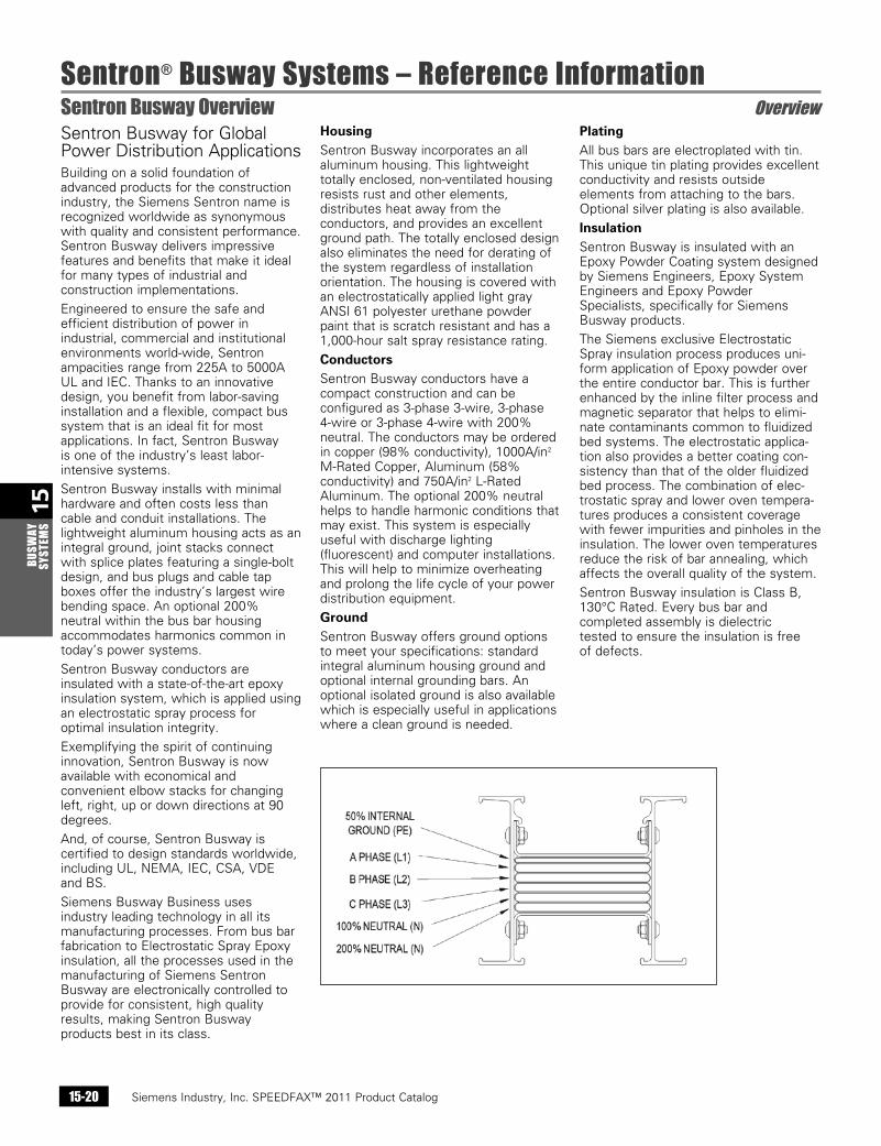
Housing Sentron Busway incorporates an all aluminum housing. This lightweight totally enclosed, non-ventilated housing resists rust and other elements, distributes heat away from the conductors, and provides an excellent ground path. The totally enclosed design also eliminates the need for derating of the system regardless of installation orientation. The housing is covered with an electrostatically applied light gray ANSI 61 polyester urethane powder paint that is scratch resistant and has a 1,000-hour salt spray resistance rating.
ConductorsSentron Busway conductors have a compact construction and can be configured as 3-phase 3-wire, 3-phase 4-wire or 3-phase 4-wire with 200% neutral. The conductors may be ordered in copper (98% conductivity), 1000A/in2 M-Rated Copper, Aluminum (58% conductivity) and 750A/in2 L-Rated Aluminum. The optional 200% neutral helps to handle harmonic conditions that may exist. This system is especially useful with discharge lighting (fluorescent) and computer installations. This will help to minimize overheating and prolong the life cycle of your power distribution equipment.
GroundSentron Busway offers ground options to meet your specifications: standard integral aluminum housing ground and optional internal grounding bars. An optional isolated ground is also available which is especially useful in applications where a clean ground is needed.
PlatingAll bus bars are electroplated with tin. This unique tin plating provides excellent conductivity and resists outside elements from attaching to the bars. Optional silver plating is also available.
InsulationSentron Busway is insulated with an Epoxy Powder Coating system designed by Siemens Engineers, Epoxy System Engineers and Epoxy Powder Specialists, specifically for Siemens Busway products.
The Siemens exclusive Electrostatic Spray insulation process produces uni-form application of Epoxy powder over the entire conductor bar. This is further enhanced by the inline filter process and magnetic separator that helps to elimi-nate contaminants common to fluidized bed systems. The electrostatic applica-tion also provides a better coating con-sistency than that of the older fluidized bed process. The combination of elec-trostatic spray and lower oven tempera-tures produces a consistent coverage with fewer impurities and pinholes in the insulation. The lower oven temperatures reduce the risk of bar annealing, which affects the overall quality of the system.
Sentron Busway insulation is Class B, 130°C Rated. Every bus bar and completed assembly is dielectric tested to ensure the insulation is free of defects.
Siemens Industry, Inc. SPEEDFAX™ 2011 Product Catalog 15-21
15BUSW
AY SYSTEM
S
Sentron® Busway Systems – Reference InformationSentron Busway Overview Overview
Siemens / Speedfax Previous folio: 14-22 SS 2/13/11
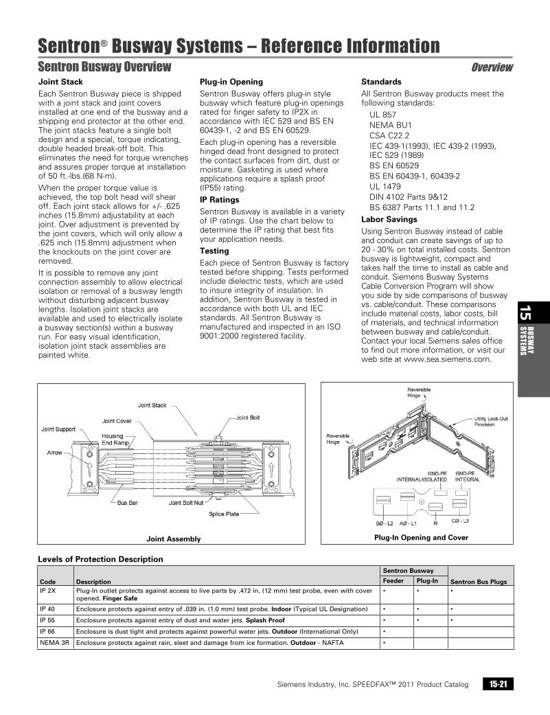
Joint Stack Each Sentron Busway piece is shipped with a joint stack and joint covers installed at one end of the busway and a shipping end protector at the other end. The joint stacks feature a single bolt design and a special, torque indicating, double headed break-off bolt. This eliminates the need for torque wrenches and assures proper torque at installation of 50 ft.-lbs.(68 N-m).
When the proper torque value is achieved, the top bolt head will shear off. Each joint stack allows for +/- .625 inches (15.8mm) adjustability at each joint. Over adjustment is prevented by the joint covers, which will only allow a .625 inch (15.8mm) adjustment when the knockouts on the joint cover are removed.
It is possible to remove any joint connection assembly to allow electrical isolation or removal of a busway length without disturbing adjacent busway lengths. Isolation joint stacks are available and used to electrically isolate a busway section(s) within a busway run. For easy visual identification, isolation joint stack assemblies are painted white.
Plug-in OpeningSentron Busway offers plug-in style busway which feature plug-in openings rated for finger safety to IP2X in accordance with IEC 529 and BS EN 60439-1, -2 and BS EN 60529.
Each plug-in opening has a reversible hinged dead front designed to protect the contact surfaces from dirt, dust or moisture. Gasketing is used where applications require a splash proof (IP55) rating.
IP RatingsSentron Busway is available in a variety of IP ratings. Use the chart below to determine the IP rating that best fits your application needs.
TestingEach piece of Sentron Busway is factory tested before shipping. Tests performed include dielectric tests, which are used to insure integrity of insulation. In addition, Sentron Busway is tested in accordance with both UL and IEC standards. All Sentron Busway is manufactured and inspected in an ISO 9001:2000 registered facility.
StandardsAll Sentron Busway products meet the following standards:
UL 857 NEMA BU1 CSA C22.2 IEC 439-1(1993), IEC 439-2 (1993),
IEC 529 (1989) BS EN 60529 BS EN 60439-1, 60439-2 UL 1479 DIN 4102 Parts 9&12 BS 6387 Parts 11.1 and 11.2
Labor SavingsUsing Sentron Busway instead of cable and conduit can create savings of up to 20 - 30% on total installed costs. Sentron busway is lightweight, compact and takes half the time to install as cable and conduit. Siemens Busway Systems Cable Conversion Program will show you side by side comparisons of busway vs. cable/conduit. These comparisons include material costs, labor costs, bill of materials, and technical information between busway and cable/conduit. Contact your local Siemens sales office to find out more information, or visit our web site at www.sea.siemens.com.
Levels of Protection Description
Code Description
Sentron Busway
Sentron Bus PlugsFeeder Plug-In
IP2X Plug-Inoutletprotectsagainstaccesstolivepartsby.472in.(12mm)testprobe,evenwithcoveropened.Finger Safe
• • •
IP40 Enclosureprotectsagainstentryof.039in.(1.0mm)testprobe.Indoor(TypicalULDesignation) • • •
IP55 Enclosureprotectsagainstentryofdustandwaterjets.Splash Proof • • •
IP66 Enclosureisdusttightandprotectsagainstpowerfulwaterjets.Outdoor(InternationalOnly) •
NEMA3R Enclosureprotectsagainstrain,sleetanddamagefromiceformation.Outdoor-NAFTA •
Joint Assembly Plug-In Opening and Cover
Siemens Industry, Inc. SPEEDFAX™ 2011 Product Catalog15-22
15BU
SWAY
SY
STEM
S
Sentron® Busway Systems – Reference InformationSentron Bus Plug Overview Overview
Siemens / Speedfax Previous folio: 14-23 NO Edits rev2
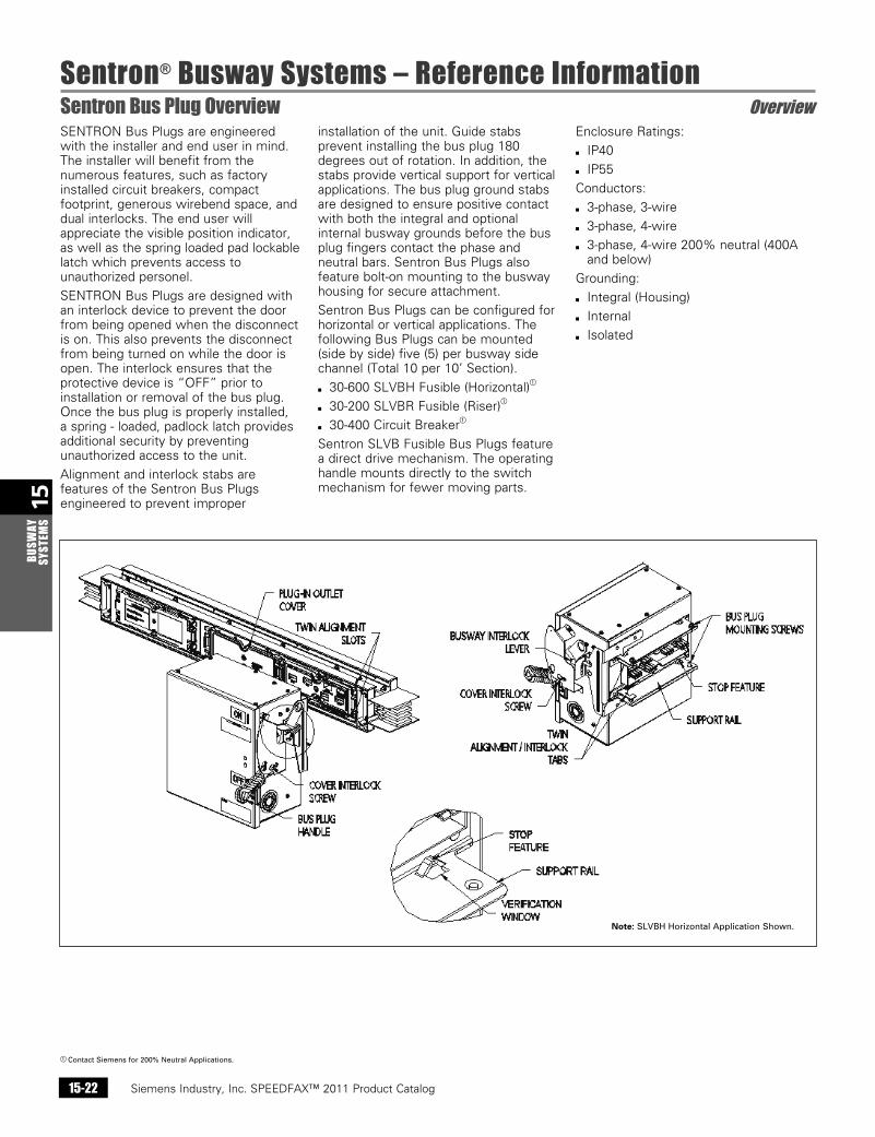
SENTRON Bus Plugs are engineered with the installer and end user in mind. The installer will benefit from the numerous features, such as factory installed circuit breakers, compact footprint, generous wirebend space, and dual interlocks. The end user will appreciate the visible position indicator, as well as the spring loaded pad lockable latch which prevents access to unauthorized personel.
SENTRON Bus Plugs are designed with an interlock device to prevent the door from being opened when the disconnect is on. This also prevents the disconnect from being turned on while the door is open. The interlock ensures that the protective device is “OFF” prior to installation or removal of the bus plug. Once the bus plug is properly installed, a spring - loaded, padlock latch provides additional security by preventing unauthorized access to the unit.
Alignment and interlock stabs are features of the Sentron Bus Plugs engineered to prevent improper
installation of the unit. Guide stabs prevent installing the bus plug 180 degrees out of rotation. In addition, the stabs provide vertical support for vertical applications. The bus plug ground stabs are designed to ensure positive contact with both the integral and optional internal busway grounds before the bus plug fingers contact the phase and neutral bars. Sentron Bus Plugs also feature bolt-on mounting to the busway housing for secure attachment.
Sentron Bus Plugs can be configured for horizontal or vertical applications. The following Bus Plugs can be mounted (side by side) five (5) per busway side channel (Total 10 per 10’ Section).
b 30-600 SLVBH Fusible (Horizontal)a
b 30-200 SLVBR Fusible (Riser)a
b 30-400 Circuit Breakera
Sentron SLVB Fusible Bus Plugs feature a direct drive mechanism. The operating handle mounts directly to the switch mechanism for fewer moving parts.
Enclosure Ratings:
b IP40
b IP55
Conductors:
b 3-phase, 3-wire
b 3-phase, 4-wire
b 3-phase, 4-wire 200% neutral (400A and below)
Grounding:
b Integral (Housing)
b Internal
b Isolated
a ContactSiemensfor200%NeutralApplications.
Note:SLVBHHorizontalApplicationShown.
Siemens Industry, Inc. SPEEDFAX™ 2011 Product Catalog 15-23
15BUSW
AY SYSTEM
S
Sentron® Busway Systems – Reference InformationTechnical Data Technical
Siemens / Speedfax Previous folio: 14-24 NO Edits rev2
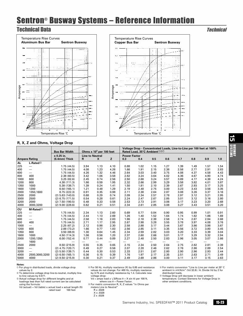
Voltage Drop - Concentrated Loads, Line-to-Line per 100 feet at 100% Bus Bar Width Ohms x 103 per 100 feet Rated Load, 35°C Ambientacg
x 0.25 in. Line to Neutral Power Factor Ampere Rating (6.4mm) Thick R X Z 0.3 0.4 0.5 0.6 0.7 0.8 0.9 1.0
AL L-Ratedc 225 — 1.75(44.5) 3.94 1.13 4.10 0.88 1.02 1.15 1.27 1.39 1.49 1.57 1.54400 — 1.75(44.5) 4.08 1.23 4.26 1.66 1.91 2.15 2.38 2.58 2.77 2.91 2.83600 — 1.75(44.5) 4.26 1.32 4.46 2.64 3.03 3.40 3.75 4.08 4.37 4.58 4.43800 400 2.38(60.5) 3.42 1.06 3.58 2.82 3.24 3.64 4.02 4.36 4.67 4.90 4.741000 600 3.25(82.6) 2.45 0.74 2.56 2.50 2.88 3.24 3.57 3.89 4.17 4.38 4.241200 800 4.38(111.3) 1.86 0.59 1.95 2.32 2.66 2.99 3.29 3.58 3.82 4.01 3.871350 1000 5.38(138.7) 1.39 0.24 1.41 1.50 1.81 2.10 2.39 2.67 2.93 3.17 3.251600 1200 6.50(165.1) 1.21 0.48 1.29 2.19 2.48 2.75 3.00 3.23 3.43 3.56 3.352000 1350,1600 8.75(222.3) 0.91 0.35 0.98 2.11 2.38 2.64 2.87 3.08 3.26 3.37 3.162500 2000 (2)5.63(143.0) 0.68 0.29 0.74 2.09 2.34 2.57 2.78 2.97 3.12 3.21 2.953000 2500 (2)6.75(171.5) 0.54 0.28 0.61 2.24 2.47 2.67 2.85 3.01 3.12 3.16 2.803200 2000 (2)7.50(190.5) 0.48 0.33 0.58 2.53 2.73 2.91 3.06 3.17 3.23 3.20 2.684000 3000,3200 (2)9.00(228.6) 0.62 0.21 0.51 2.34 2.61 2.85 3.08 3.27 3.43 3.51 3.20
CU M-Ratedc 225 — 1.75(44.5) 2.34 1.13 2.60 0.69 0.77 0.84 0.90 0.95 0.99 1.01 0.91400 — 1.75(44.5) 2.44 1.13 2.69 1.26 1.40 1.52 1.64 1.74 1.82 1.86 1.69600 — 1.75(44.5) 2.58 1.16 2.83 1.96 2.18 2.39 2.58 2.74 2.87 2.94 2.68800 400 1.75(44.5) 2.71 1.17 2.95 2.67 2.98 3.28 3.55 3.78 3.97 4.08 3.761000 — 2.25(67.2) 2.12 0.98 2.30 2.58 2.88 3.17 3.44 3.67 3.86 3.98 3.671200 600 2.88(73.2) 1.66 0.77 1.83 2.56 2.85 3.11 3.35 3.56 3.72 3.80 3.451350 800 3.50(88.9) 1.30 0.64 1.45 2.34 2.59 2.82 3.03 3.20 3.33 3.39 3.041600 1000 4.50(114.3) 1.06 0.56 1.20 2.37 2.60 2.66 3.01 3.17 3.29 3.32 2.942000 1200,1350 6.00(152.4) 0.77 0.44 0.89 2.27 2.48 2.50 2.83 2.96 3.05 3.07 2.66— 1600 — — — — — — — — — — — —2500 2000 8.50(215.9) 0.55 0.35 0.65 2.15 2.34 2.50 2.64 2.75 2.82 2.81 2.393000 — (2)4.75(120.7) 0.49 0.27 0.56 2.07 2.28 2.46 2.62 2.76 2.86 2.89 2.543200 — (2)5.50(139.7) 0.44 0.30 0.53 2.33 2.51 2.67 2.80 2.90 2.96 2.93 2.444000 2500,3000,3200 (2)6.50(165.1) 0.36 0.15 0.39 1.76 1.97 2.17 2.35 2.51 2.63 2.71 2.495000 4000 (2)8.50(215.9) 0.30 0.21 0.37 2.49 2.69 2.86 3.00 3.11 3.17 3.15 2.63
Notes:aForplug-indistributedloads,dividevoltagedrop
valuesby2.bTodeterminevoltagedropline-to-neutral,multiplyline-
to-linevaluesby0.577.cActualvoltagedropfordifferentlengthsandat
loadingslessthanfullratedcurrentcanbecalculatedusingtheformula:Vd(actual)=Vd(table)xactualloadxactuallength(ft)ratedload100feet
dFor50Hz,multiplyreactance(X)by0.85andresistancevaluesdonotchange.For400Hz,multiplyreactanceby3.75andmultiplyresistanceby1.4.Calculatenewvoltagedrop:Vd=ampsloadxE3(Rcosθ+Xsinθ)per100ft,wherecosθ=PowerFactor.
eFormetricconversionR,X,Zvalues”inOhmspermetersLinetoNeutral”Rx.0328Xx.0328Zx.0328
fFormetricconversion”LinetoLinepermeterat25°CambientinmV/A/m”(Vd32.8)/A.DivideVdby2fordistributedloads.
gVoltageDropwilldecreaseinlowerambienttemperature.ContactSiemensforVoltageDropinotherambientconditions.
R, X, Z and Ohms, Voltage Drop
TemperatureRiseCurvesAluminum Bus Bar Sentron Busway
TemperatureRiseCurvesCopper Bus Bar Sentron Busway
Am
per
age
Am
per
age
TemperatureRise˚C TemperatureRise˚C
Siemens Industry, Inc. SPEEDFAX™ 2011 Product Catalog15-24
15BU
SWAY
SY
STEM
S
Sentron® Busway Systems – Reference InformationTechnical Data Technical
Siemens / Speedfax Previous folio: 14-25 NO Edits rev2
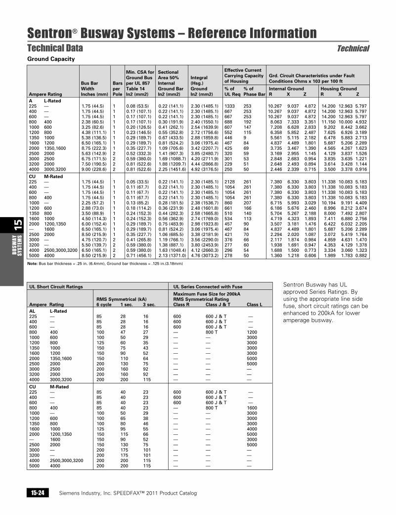
Min. CSA for Sectional Effective Current Ground Bus Area 50% Integral Carrying Capacity Grd. Circuit Characteristics under Fault Bus Bar Bars per UL 857 Internal (Hsg.) of Housing Conditions Ohms x 103 per 100 ft
Width per Table 14 Ground Bar Ground % of % of Internal Ground Housing Ground Ampere Rating Inches (mm) Pole In2 (mm2) In2 (mm2) In2 (mm2) UL Req Phase Bar R X Z R X Z A L-Rated 225 — 1.75(44.5) 1 0.08(53.5) 0.22(141.1) 2.30(1485.1) 1333 253 10.267 9.037 4.872 14.200 12.963 5.797 400 — 1.75(44.5) 1 0.17(107.1) 0.22(141.1) 2.30(1485.1) 667 253 10.267 9.037 4.872 14.200 12.963 5.797 600 — 1.75(44.5) 1 0.17(107.1) 0.22(141.1) 2.30(1485.1) 667 253 10.267 9.037 4.872 14.200 12.963 5.797 800 400 2.38(60.5) 1 0.17(107.1) 0.30(191.9) 2.40(1550.1) 688 192 8.063 7.333 3.351 11.150 10.000 4.932 1000 600 3.25(82.6) 1 0.20(126.5) 0.41(262.1) 2.54(1639.9) 607 147 7.208 6.628 2.833 9.202 8.442 3.662 1200 800 4.38(111.1) 1 0.23(146.5) 0.55(352.8) 2.72(1756.6) 552 115 6.358 5.852 2.487 7.625 6.926 3.189 1350 1000 5.38(136.5) 1 0.29(189.7) 0.67(433.5) 2.88(1859.8) 446 9 5.561 5.115 2.182 6.478 5.883 2.713 1600 1200 6.50(165.1) 1 0.29(189.7) 0.81(524.2) 3.06(1975.4) 467 84 4.837 4.489 1.801 5.687 5.206 2.289 2000 1350,1600 8.75(222.3) 1 0.35(227.7) 1.09(705.6) 3.42(2207.7) 425 69 3.735 3.467 1.390 4.565 4.267 1.623 2500 2000 5.63(142.9) 2 0.52(332.3) 1.41(907.3) 3.85(2480.7) 320 59 3.169 2.955 1.145 4.129 3.837 1.526 3000 2500 6.75(171.5) 2 0.59(380.0) 1.69(1088.7) 4.20(2711.9) 301 53 2.848 2.683 0.954 3.835 3.635 1.221 3200 2000 7.50(190.5) 2 0.81(522.6) 1.88(1209.7) 4.44(2866.8) 229 51 2.648 2.493 0.894 3.614 3.428 1.144 4000 3000,3200 9.00(228.6) 2 0.81(522.6) 2.25(1451.6) 4.92(3176.5) 250 50 2.446 2.339 0.715 3.500 3.378 0.916
CU M-Rated 225 — 1.75(44.5) 1 0.05(33.5) 0.22(141.1) 2.30(1485.1) 2128 261 7.380 6.330 3.803 11.338 10.083 5.183 400 — 1.75(44.5) 1 0.11(67.7) 0.22(141.1) 2.30(1485.1) 1054 261 7.380 6.330 3.803 11.338 10.083 5.183 600 — 1.75(44.5) 1 0.11(67.7) 0.22(141.1) 2.30(1485.1) 1054 261 7.380 6.330 3.803 11.338 10.083 5.183 800 400 1.75(44.5) 1 0.11(67.7) 0.22(141.1) 2.30(1485.1) 1054 261 7.380 6.330 3.803 11.338 10.083 5.183 1000 — 2.25(57.2) 1 0.13(85.2) 0.28(181.5) 2.38(1536.7) 860 207 6.715 5.993 3.029 10.194 9.191 4.409 1200 600 2.88(73.0) 1 0.18(114.2) 0.36(231.9) 2.48(1601.8) 661 166 6.186 5.676 2.460 8.996 8.212 3.674 1350 800 3.50(88.9) 1 0.24(152.3) 0.44(282.3) 2.58(1665.8) 510 140 5.704 5.267 2.188 8.000 7.492 2.807 1600 1000 4.50(114.3) 1 0.24(152.3) 0.56(362.9) 2.74(1769.0) 534 113 4.719 4.323 1.893 7.411 6.880 2.756 2000 1200,1350 6.00(152.4) 1 0.29(189.7) 0.75(483.9) 2.98(1923.8) 457 90 3.507 3.181 1.476 6.422 6.032 2.205 — 1600 6.50(165.1) 1 0.29(189.7) 0.81(524.2) 3.06(1975.4) 467 84 4.837 4.489 1.801 5.687 5.206 2.289 2500 2000 8.50(215.9) 1 0.35(227.7) 1.06(685.5) 3.38(2181.9) 421 70 2.294 2.020 1.087 3.072 5.419 1.764 3000 — 4.75(120.7) 2 0.41(265.8) 1.19(766.1) 3.56(2290.0) 376 66 2.117 1.874 0.984 4.859 4.631 1.470 3200 — 5.50(139.7) 2 0.59(380.0) 1.38(887.1) 3.80(2453.9) 277 60 1.938 1.691 0.947 4.353 4.129 1.378 4000 2500,3000,3200 6.50(165.1) 2 0.59(380.0) 1.63(1048.4) 4.12(2660.3) 296 54 1.688 1.500 0.773 3.334 3.060 1.323 5000 4000 8.50(215.9) 2 0.71(456.1) 2.13(1371.0) 4.76(3073.2) 278 50 1.360 1.218 0.606 1.989 1.783 0.882
Ground Capacity
Sentron Busway has UL approved Series Ratings. By using the appropriate line side fuse, short circuit ratings can be enhanced to 200kA for lower amperage busway.
Note:Busbarthickness=.25in.(6.4mm),Groundbarthickness=.125in.(3.18mm)
UL Short Circuit Ratings UL Series Connected with Fuse
Maximum Fuse Size for 200kA RMS Symmetrical (kA) RMS Symmetrical Rating Ampere Rating 6 cycle 1 sec. 3 sec. Class R Class J & T Class L AL L-Rated 225 — 85 28 16 600 600J&T — 400 — 85 28 16 600 600J&T — 600 — 85 28 16 600 600J&T — 800 400 100 47 27 — 800T 1200 1000 600 100 50 29 — — 3000 1200 800 125 60 35 — — 3000 1350 1000 150 75 43 — — 3000 1600 1200 150 90 52 — — 3000 2000 1350,1600 150 110 64 — — 5000 2500 2000 200 130 75 — — 5000 3000 2500 200 160 92 — — — 3200 2000 200 160 92 — — — 4000 3000,3200 200 200 115 — — —
CU M-Rated 225 — 85 40 23 600 600J&T — 400 — 85 40 23 600 600J&T — 600 — 85 40 23 600 600J&T — 800 400 85 40 23 — 800T 1600 1000 — 100 50 29 — — 3000 1200 600 100 65 38 — — 3000 1350 800 100 80 46 — — 3000 1600 1000 125 95 55 — — 4000 2000 1200,1350 150 115 66 — — 5000 — 1600 150 90 52 — — 3000 2500 2000 150 130 75 — — 5000 3000 — 200 175 101 — — — 3200 — 200 175 101 — — — 4000 2500,3000,3200 200 200 115 — — — 5000 4000 200 200 115 — — —
Siemens Industry, Inc. SPEEDFAX™ 2011 Product Catalog 15-25
15BUSW
AY SYSTEM
S
Sentron® Busway Systems – Reference InformationStraight Sections – Plug-In, Riser and Feeder Selection
Siemens / Speedfax Previous folio: 14-26 NO Edits rev2
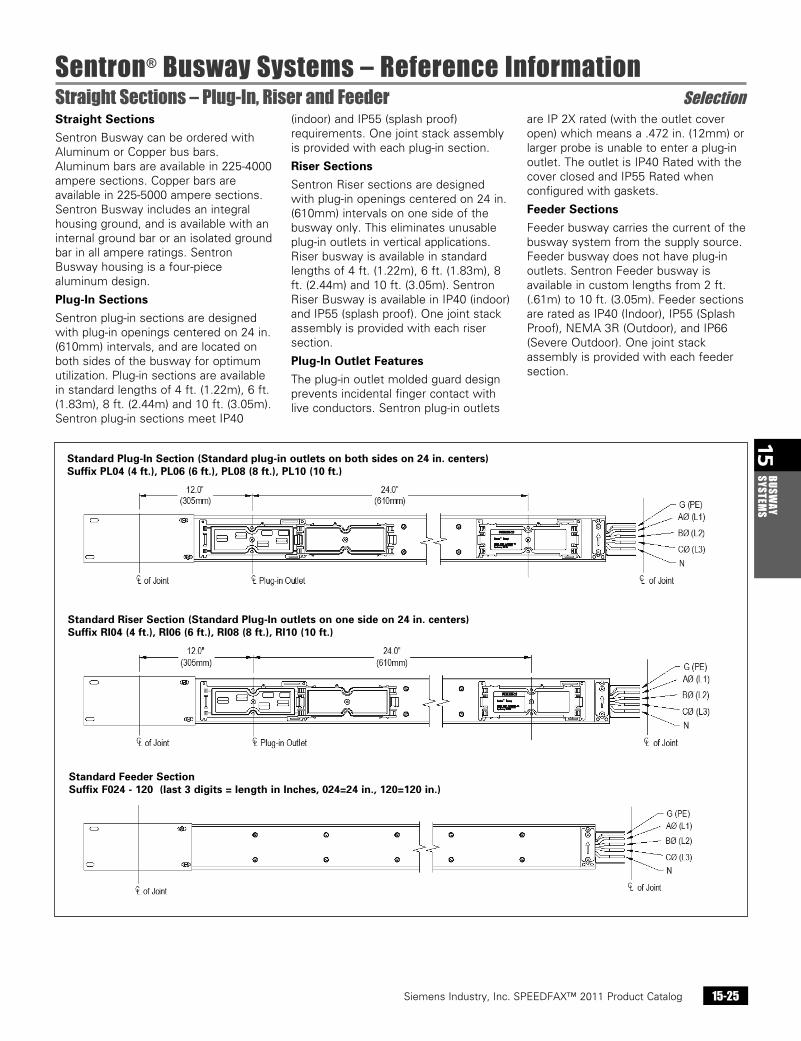
Straight Sections
Sentron Busway can be ordered with Aluminum or Copper bus bars. Aluminum bars are available in 225-4000 ampere sections. Copper bars are available in 225-5000 ampere sections. Sentron Busway includes an integral housing ground, and is available with an internal ground bar or an isolated ground bar in all ampere ratings. Sentron Busway housing is a four-piece aluminum design.
Plug-In Sections
Sentron plug-in sections are designed with plug-in openings centered on 24 in. (610mm) intervals, and are located on both sides of the busway for optimum utilization. Plug-in sections are available in standard lengths of 4 ft. (1.22m), 6 ft. (1.83m), 8 ft. (2.44m) and 10 ft. (3.05m). Sentron plug-in sections meet IP40
(indoor) and IP55 (splash proof) requirements. One joint stack assembly is provided with each plug-in section.
Riser Sections
Sentron Riser sections are designed with plug-in openings centered on 24 in. (610mm) intervals on one side of the busway only. This eliminates unusable plug-in outlets in vertical applications. Riser busway is available in standard lengths of 4 ft. (1.22m), 6 ft. (1.83m), 8 ft. (2.44m) and 10 ft. (3.05m). Sentron Riser Busway is available in IP40 (indoor) and IP55 (splash proof). One joint stack assembly is provided with each riser section.
Plug-In Outlet Features
The plug-in outlet molded guard design prevents incidental finger contact with live conductors. Sentron plug-in outlets
are IP 2X rated (with the outlet cover open) which means a .472 in. (12mm) or larger probe is unable to enter a plug-in outlet. The outlet is IP40 Rated with the cover closed and IP55 Rated when configured with gaskets.
Feeder Sections
Feeder busway carries the current of the busway system from the supply source. Feeder busway does not have plug-in outlets. Sentron Feeder busway is available in custom lengths from 2 ft. (.61m) to 10 ft. (3.05m). Feeder sections are rated as IP40 (Indoor), IP55 (Splash Proof), NEMA 3R (Outdoor), and IP66 (Severe Outdoor). One joint stack assembly is provided with each feeder section.
Standard Plug-In Section (Standard plug-in outlets on both sides on 24 in. centers) Suffix PL04 (4 ft.), PL06 (6 ft.), PL08 (8 ft.), PL10 (10 ft.)
Standard Riser Section (Standard Plug-In outlets on one side on 24 in. centers) Suffix RI04 (4 ft.), RI06 (6 ft.), RI08 (8 ft.), RI10 (10 ft.)
Standard Feeder Section Suffix F024 - 120 (last 3 digits = length in Inches, 024=24 in., 120=120 in.)
Siemens Industry, Inc. SPEEDFAX™ 2011 Product Catalog15-26
15BU
SWAY
SY
STEM
S
Sentron® Busway Systems – Reference Information Selection
Siemens / Speedfax Previous folio: 14-27 NO Edits rev2
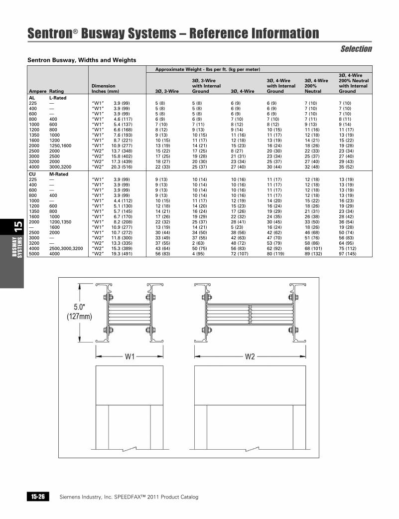
Sentron Busway, Widths and Weights
Approximate Weight - lbs per ft. (kg per meter) 3Ø, 4-Wire 3Ø, 3-Wire 3Ø, 4-Wire 3Ø, 4-Wire 200% Neutral Dimension with Internal with Internal 200% with Internal Ampere Rating Inches (mm) 3Ø, 3-Wire Ground 3Ø, 4-Wire Ground Neutral Ground AL L-Rated 225 — “W1” 3.9(99) 5(8) 5(8) 6(9) 6(9) 7(10) 7(10)400 — “W1” 3.9(99) 5(8) 5(8) 6(9) 6(9) 7(10) 7(10)600 — “W1” 3.9(99) 5(8) 5(8) 6(9) 6(9) 7(10) 7(10)800 400 “W1” 4.6(117) 6(9) 6(9) 7(10) 7(10) 7(11) 8(11)1000 600 “W1” 5.4(137) 7(10) 7(11) 8(12) 8(12) 9(13) 9(14)1200 800 “W1” 6.6(168) 8(12) 9(13) 9(14) 10(15) 11(16) 11(17)1350 1000 “W1” 7.6(193) 9(13) 10(15) 11(16) 11(17) 12(18) 13(19)1600 1200 “W1” 8.7(221) 10(15) 11(17) 12(18) 13(19) 14(21) 15(22)2000 1250,1600 “W1” 10.9(277) 13(19) 14(21) 15(23) 16(24) 18(26) 19(28)2500 2000 “W2” 13.7(348) 15(22) 17(25) 8(27) 20(30) 22(33) 23(34)3000 2500 “W2” 15.8(402) 17(25) 19(28) 21(31) 23(34) 25(37) 27(40)3200 2000 “W2” 17.3(439) 18(27) 20(30) 23(34) 25(37) 27(40) 29(43)4000 3000,3200 “W2” 20.3(516) 22(33) 25(37) 27(40) 30(44) 32(48) 35(52)
CU M-Rated225 — “W1” 3.9(99) 9(13) 10(14) 10(16) 11(17) 12(18) 13(19)400 — “W1” 3.9(99) 9(13) 10(14) 10(16) 11(17) 12(18) 13(19)600 — “W1” 3.9(99) 9(13) 10(14) 10(16) 11(17) 12(18) 13(19)800 400 “W1” 3.9(99) 9(13) 10(14) 10(16) 11(17) 12(18) 13(19)1000 — “W1” 4.4(112) 10(15) 11(17) 12(19) 14(20) 15(22) 16(23)1200 600 “W1” 5.1(130) 12(18) 14(20) 15(23) 16(24) 18(26) 19(29)1350 800 “W1” 5.7(145) 14(21) 16(24) 17(26) 19(29) 21(31) 23(34)1600 1000 “W1” 6.7(170) 17(26) 19(29) 22(32) 24(35) 26(38) 28(42)2000 1200,1350 “W1” 8.2(208) 22(32) 25(37) 28(41) 30(45) 33(50) 36(54)— 1600 “W1” 10.9(277) 13(19) 14(21) 5(23) 16(24) 18(26) 19(28)2500 2000 “W1” 10.7(272) 30(44) 34(50) 38(56) 42(62) 46(68) 50(74)3000 — “W2” 11.8(300) 33(49) 37(55) 42(63) 47(70) 51(76) 56(83)3200 — “W2” 13.3(335) 37(55) 2(63) 48(72) 53(79) 58(86) 64(95)4000 2500,3000,3200 “W2” 15.3(389) 43(64) 50(75) 56(83) 62(92) 68(101) 75(112)5000 4000 “W2” 19.3(491) 56(83) 4(95) 72(107) 80(119) 89(132) 97(145)
Siemens Industry, Inc. SPEEDFAX™ 2011 Product Catalog 15-27
15BUSW
AY SYSTEM
S
Sentron® Busway Systems – Reference InformationElbows Selection
Siemens / Speedfax Previous folio: 14-28 NO Edits rev2
Edge Down Edge Up
Suffix ESED Suffix ESEU
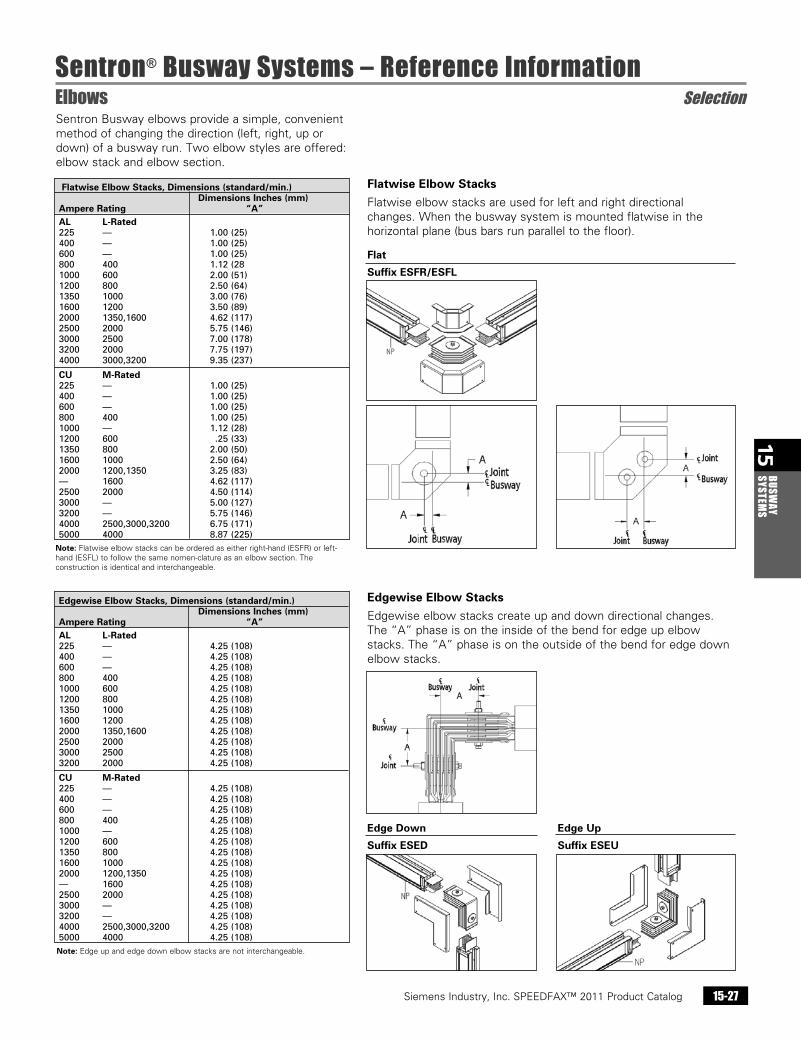
Edgewise Elbow Stacks
Edgewise elbow stacks create up and down directional changes. The “A” phase is on the inside of the bend for edge up elbow stacks. The “A” phase is on the outside of the bend for edge down elbow stacks.
Flatwise Elbow Stacks
Flatwise elbow stacks are used for left and right directional changes. When the busway system is mounted flatwise in the horizontal plane (bus bars run parallel to the floor).
Edgewise Elbow Stacks, Dimensions (standard/min.) Dimensions Inches (mm) Ampere Rating “A” AL L-Rated 225 — 4.25(108) 400 — 4.25(108) 600 — 4.25(108) 800 400 4.25(108) 1000 600 4.25(108) 1200 800 4.25(108) 1350 1000 4.25(108) 1600 1200 4.25(108) 2000 1350,1600 4.25(108) 2500 2000 4.25(108) 3000 2500 4.25(108) 3200 2000 4.25(108)
CU M-Rated 225 — 4.25(108) 400 — 4.25(108) 600 — 4.25(108) 800 400 4.25(108) 1000 — 4.25(108) 1200 600 4.25(108) 1350 800 4.25(108) 1600 1000 4.25(108) 2000 1200,1350 4.25(108) — 1600 4.25(108) 2500 2000 4.25(108) 3000 — 4.25(108) 3200 — 4.25(108) 4000 2500,3000,3200 4.25(108) 5000 4000 4.25(108)
Flatwise Elbow Stacks, Dimensions (standard/min.) Dimensions Inches (mm) Ampere Rating “A” AL L-Rated 225 — 1.00(25) 400 — 1.00(25) 600 — 1.00(25) 800 400 1.12(28 1000 600 2.00(51) 1200 800 2.50(64) 1350 1000 3.00(76) 1600 1200 3.50(89) 2000 1350,1600 4.62(117) 2500 2000 5.75(146) 3000 2500 7.00(178) 3200 2000 7.75(197) 4000 3000,3200 9.35(237)
CU M-Rated 225 — 1.00(25) 400 — 1.00(25) 600 — 1.00(25) 800 400 1.00(25) 1000 — 1.12(28) 1200 600 .25(33) 1350 800 2.00(50) 1600 1000 2.50(64) 2000 1200,1350 3.25(83) — 1600 4.62(117) 2500 2000 4.50(114) 3000 — 5.00(127) 3200 — 5.75(146) 4000 2500,3000,3200 6.75(171) 5000 4000 8.87(225)Note: Flatwise elbow stacks can be ordered as either right-hand (ESFR) or left-hand (ESFL) to follow the same nomen-clature as an elbow section. The construction is identical and interchangeable.
Sentron Busway elbows provide a simple, convenient method of changing the direction (left, right, up or down) of a busway run. Two elbow styles are offered: elbow stack and elbow section.
Note: Edge up and edge down elbow stacks are not interchangeable.
Flat
Suffix ESFR/ESFL
Siemens Industry, Inc. SPEEDFAX™ 2011 Product Catalog15-28
15BU
SWAY
SY
STEM
S
Sentron® Busway Systems – Reference InformationElbows Selection
Siemens / Speedfax Previous folio: 14-29 NO Edits rev2
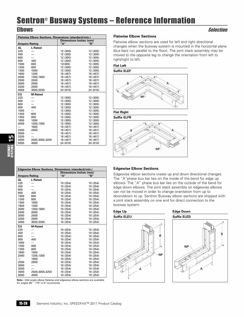
Flatwise Elbow Sections
Flatwise elbow sections are used for left and right directional changes when the busway system is mounted in the horizontal plane (bus bars run parallel to the floor). The joint stack assembly may be moved to the opposite leg to change the orientation from left to right/right to left.
Edgewise Elbow Sections
Edgewise elbow sections create up and down directional changes. The “A”phase bus bar lies on the inside of the bend for edge up elbows. The “A” phase bus bar lies on the outside of the bend for edge down elbows. The joint stack assembly on edgewise elbows can not be moved in order to change orientation from up to down/down to up. Sentron Busway elbow sections are shipped with a joint stack assembly on one end for direct connection to the busway system.
Flatwise Elbow Sections, Dimensions (standard/min.) Dimensions Inches (mm) Ampere Rating “A” ”B” AL L-Rated 225 — 12(305) 12(305) 400 — 12(305) 12(305) 600 — 12(305) 12(305) 800 400 12(305) 12(305) 1000 600 12(305) 12(305) 1200 800 12(305) 12(305) 1350 1000 12(305) 12(305) 1600 1200 18(457) 18(457) 2000 1350,1600 18(457) 18(457) 2500 2000 18(457) 18(457) 3000 2500 18(457) 18(457) 3200 2000 18(457) 18(457) 4000 3000,3200 24(610) 24(610)
CU M-Rated 225 — 12(305) 12(305) 400 — 12(305) 12(305) 600 — 12(305) 12(305) 800 400 12(305) 12(305) 1000 — 12(305) 12(305) 1200 600 12(305) 12(305) 1350 800 12(305) 12(305) 1600 1000 12(305) 12(305) 2000 1200,1350 12(305) 12(305) — 1600 18(457) 18(457) 2500 2000 18(457) 18(457) 3000 — 18(457) 18(457) 3200 — 18(457) 18(457) 4000 2500,3000,3200 18(457) 18(457) 5000 4000 24(610) 24(610)
Edgewise Elbow Sections, Dimensions (standard/min.) Dimensions Inches (mm) Ampere Rating “A” ”B” AL L-Rated 225 — 10(254) 10(254) 400 — 10(254) 10(254) 600 — 10(254) 10(254) 800 400 10(254) 10(254) 1000 600 10(254) 10(254) 1200 800 10(254) 10(254) 1350 1000 10(254) 10(254) 1600 1200 10(254) 10(254) 2000 1350,1600 10(254) 10(254) 2500 2000 10(254) 10(254) 3000 2500 10(254) 10(254) 3200 2000 10(254) 10(254) 4000 3000,3200 10(254) 10(254)
CU M-Rated 225 — 10(254) 10(254) 400 — 10(254) 10(254) 600 — 10(254) 10(254) 800 400 10(254) 10(254) 1000 — 10(254) 10(254) 1200 600 10(254) 10(254) 1350 800 10(254) 10(254) 1600 1000 10(254) 10(254) 2000 1200,1350 10(254) 10(254) — 1600 10(254) 10(254) 2500 2000 10(254) 10(254) 3000 — 10(254) 10(254) 3200 — 10(254) 10(254) 4000 2500,3000,3200 10(254) 10(254) 5000 4000 10(254) 10(254)
Note :Oddangleelbowflatwiseandedgewiseelbowsectionsareavailableforangles95°-175°in5°increments.
Flat Right
Suffix ELFR
Flat Left
Suffix ELEF
Edge Up Edge Down
Suffix ELEU Suffix ELED
Siemens Industry, Inc. SPEEDFAX™ 2011 Product Catalog 15-29
15BUSW
AY SYSTEM
S
Sentron® Busway Systems – Reference InformationOffsets Selection
Siemens / Speedfax Previous folio: 14-30 SS 2/13/11
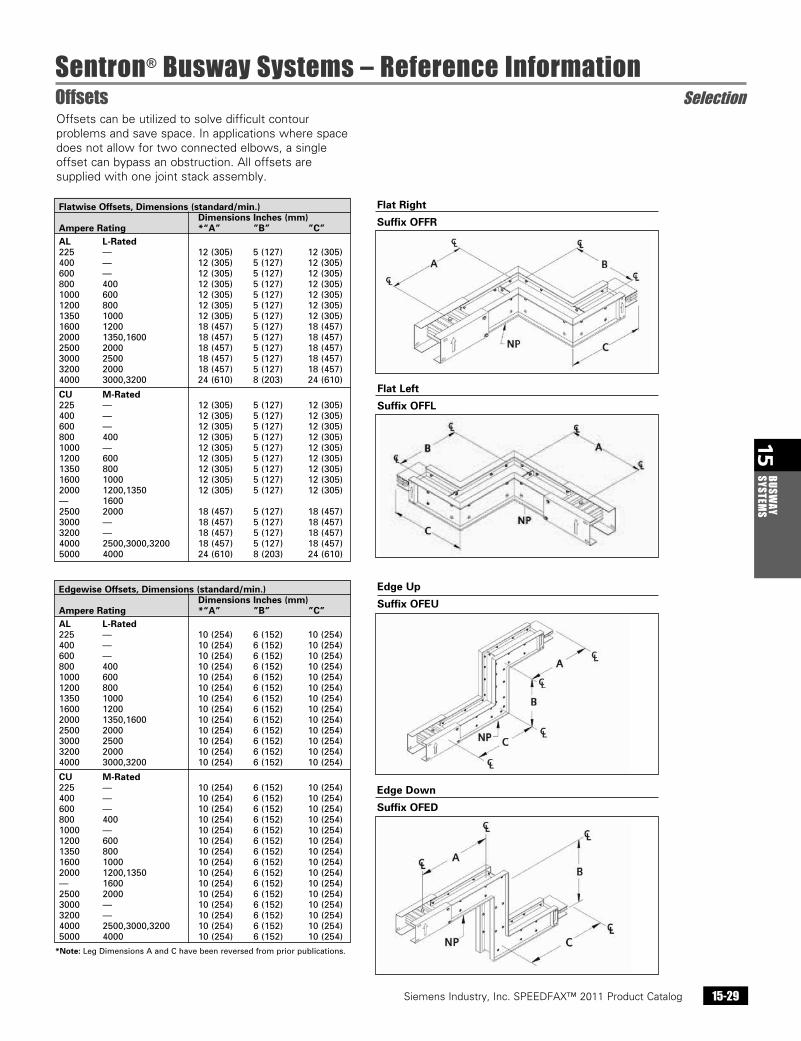
Edge Up
Suffix OFEU
Offsets can be utilized to solve difficult contour problems and save space. In applications where space does not allow for two connected elbows, a single offset can bypass an obstruction. All offsets are supplied with one joint stack assembly.
Flatwise Offsets, Dimensions (standard/min.) Dimensions Inches (mm) Ampere Rating *“A” ”B” ”C” AL L-Rated 225 — 12(305) 5(127) 12(305) 400 — 12(305) 5(127) 12(305) 600 — 12(305) 5(127) 12(305) 800 400 12(305) 5(127) 12(305) 1000 600 12(305) 5(127) 12(305) 1200 800 12(305) 5(127) 12(305) 1350 1000 12(305) 5(127) 12(305) 1600 1200 18(457) 5(127) 18(457) 2000 1350,1600 18(457) 5(127) 18(457) 2500 2000 18(457) 5(127) 18(457) 3000 2500 18(457) 5(127) 18(457) 3200 2000 18(457) 5(127) 18(457) 4000 3000,3200 24(610) 8(203) 24(610)
CU M-Rated 225 — 12(305) 5(127) 12(305) 400 — 12(305) 5(127) 12(305) 600 — 12(305) 5(127) 12(305) 800 400 12(305) 5(127) 12(305) 1000 — 12(305) 5(127) 12(305) 1200 600 12(305) 5(127) 12(305) 1350 800 12(305) 5(127) 12(305) 1600 1000 12(305) 5(127) 12(305) 2000 1200,1350 12(305) 5(127) 12(305) — 1600 2500 2000 18(457) 5(127) 18(457) 3000 — 18(457) 5(127) 18(457) 3200 — 18(457) 5(127) 18(457) 4000 2500,3000,3200 18(457) 5(127) 18(457) 5000 4000 24(610) 8(203) 24(610)
Edgewise Offsets, Dimensions (standard/min.) Dimensions Inches (mm) Ampere Rating *“A” ”B” ”C” AL L-Rated 225 — 10(254) 6(152) 10(254) 400 — 10(254) 6(152) 10(254) 600 — 10(254) 6(152) 10(254) 800 400 10(254) 6(152) 10(254) 1000 600 10(254) 6(152) 10(254) 1200 800 10(254) 6(152) 10(254) 1350 1000 10(254) 6(152) 10(254) 1600 1200 10(254) 6(152) 10(254) 2000 1350,1600 10(254) 6(152) 10(254) 2500 2000 10(254) 6(152) 10(254) 3000 2500 10(254) 6(152) 10(254) 3200 2000 10(254) 6(152) 10(254) 4000 3000,3200 10(254) 6(152) 10(254)
CU M-Rated 225 — 10(254) 6(152) 10(254) 400 — 10(254) 6(152) 10(254) 600 — 10(254) 6(152) 10(254) 800 400 10(254) 6(152) 10(254) 1000 — 10(254) 6(152) 10(254) 1200 600 10(254) 6(152) 10(254) 1350 800 10(254) 6(152) 10(254) 1600 1000 10(254) 6(152) 10(254) 2000 1200,1350 10(254) 6(152) 10(254) — 1600 10(254) 6(152) 10(254) 2500 2000 10(254) 6(152) 10(254) 3000 — 10(254) 6(152) 10(254) 3200 — 10(254) 6(152) 10(254) 4000 2500,3000,3200 10(254) 6(152) 10(254) 5000 4000 10(254) 6(152) 10(254)
Edge Down
Suffix OFED
Flat Right
Suffix OFFR
Flat Left
Suffix OFFL
*Note:LegDimensionsAandChavebeenreversedfrompriorpublications.
Siemens Industry, Inc. SPEEDFAX™ 2011 Product Catalog15-30
15BU
SWAY
SY
STEM
S
Sentron® Busway Systems – Reference InformationCombinations Selection
Siemens / Speedfax Previous folio: 14-31 SS 2/13/11
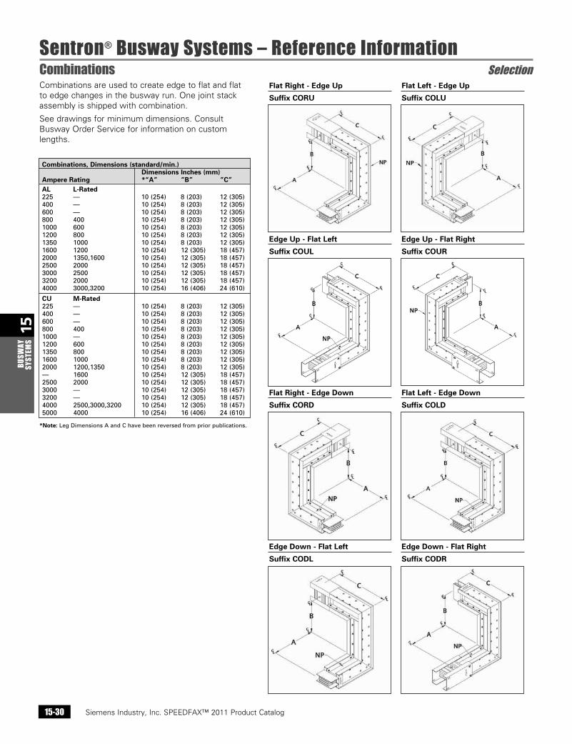
Flat Right - Edge Up Flat Left - Edge Up
Suffix CORU Suffix COLU
Edge Up - Flat Left Edge Up - Flat Right
Suffix COUL Suffix COUR
Flat Right - Edge Down Flat Left - Edge Down
Suffix CORD Suffix COLD
Edge Down - Flat Left Edge Down - Flat Right
Suffix CODL Suffix CODR
Combinations are used to create edge to flat and flat to edge changes in the busway run. One joint stack assembly is shipped with combination.
See drawings for minimum dimensions. Consult Busway Order Service for information on custom lengths.
Combinations, Dimensions (standard/min.) Dimensions Inches (mm) Ampere Rating *“A” ”B” ”C” AL L-Rated 225 — 10(254) 8(203) 12(305) 400 — 10(254) 8(203) 12(305) 600 — 10(254) 8(203) 12(305) 800 400 10(254) 8(203) 12(305) 1000 600 10(254) 8(203) 12(305) 1200 800 10(254) 8(203) 12(305) 1350 1000 10(254) 8(203) 12(305) 1600 1200 10(254) 12(305) 18(457) 2000 1350,1600 10(254) 12(305) 18(457) 2500 2000 10(254) 12(305) 18(457) 3000 2500 10(254) 12(305) 18(457) 3200 2000 10(254) 12(305) 18(457) 4000 3000,3200 10(254) 16(406) 24(610)
CU M-Rated 225 — 10(254) 8(203) 12(305) 400 — 10(254) 8(203) 12(305) 600 — 10(254) 8(203) 12(305) 800 400 10(254) 8(203) 12(305) 1000 — 10(254) 8(203) 12(305) 1200 600 10(254) 8(203) 12(305) 1350 800 10(254) 8(203) 12(305) 1600 1000 10(254) 8(203) 12(305) 2000 1200,1350 10(254) 8(203) 12(305) — 1600 10(254) 12(305) 18(457) 2500 2000 10(254) 12(305) 18(457) 3000 — 10(254) 12(305) 18(457) 3200 — 10(254) 12(305) 18(457) 4000 2500,3000,3200 10(254) 12(305) 18(457) 5000 4000 10(254) 16(406) 24(610)
*Note:LegDimensionsAandChavebeenreversedfrompriorpublications.
Siemens Industry, Inc. SPEEDFAX™ 2011 Product Catalog 15-31
15BUSW
AY SYSTEM
S
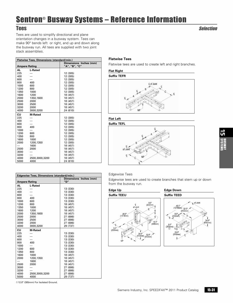
Sentron® Busway Systems – Reference InformationTees Selection
Siemens / Speedfax Previous folio: 14-32 NO Edits rev2
Flat Right
Suffix TEFR
Flat Left
Suffix TEFL
Flatwise Tees
Flatwise tees are used to create left and right branches.
Edgewise Tees
Edgewise tees are used to create branches that stem up or down from the busway run.
Flatwise Tees, Dimensions (standard/min.) Dimensions Inches (mm) Ampere Rating “A”, ”B”, ”C” AL L-Rated 225 — 12(305) 400 — 12(305) 600 — 12(305) 800 400 12(305) 1000 600 12(305) 1200 800 12(305) 1350 1000 12(305) 1600 1200 18(457) 2000 1350,1600 18(457) 2500 2000 18(457) 3000 2500 18(457) 3200 2000 18(457) 4000 3000,3200 24(610)
CU M-Rated 225 — 12(305) 400 — 12(305) 600 — 12(305) 800 400 12(305) 1000 — 12(305) 1200 600 12(305) 1350 800 12(305) 1600 1000 12(305) 2000 1200,1350 12(305) — 1600 18(457) 2500 2000 18(457) 3000 — 18(457) 3200 — 18(457) 4000 2500,3000,3200 18(457) 5000 4000 24(610)
Edgewise Tees, Dimensions (standard/min.) Dimensions Inches (mm) Ampere Rating “D” AL L-Rated 225 — 13(330) 400 — 13(330) 600 — 13(330) 800 400 13(330) 1000 600 13(330) 1200 800 18(457) 1350 1000 18(457) 1600 1200 18(457) 2000 1350,1600 18(457) 2500 2000 27(686) 3000 2500 27(686) 3200 2000 27(686) 4000 3000,3200 29(737)
CU M-Rated 225 — 13(330) 400 — 13(330) 600 — 13(330) 800 400 13(330) 1000 — 13(330) 1200 600 13(330) 1350 800 13(330) 1600 1000 18(457) 2000 1200,1350 18(457) — 1600 18(457) 2500 2000 18(457) 3000 — 27(686) 3200 — 27(686) 4000 2500,3000,3200 27(686) 5000 4000 29(737)
Edge Up Edge Down
Suffix TEEU Suffix TEED
a 12.0"(305mm)ForIsolatedGround.
Tees are used to simplify directional and plane orientation changes in a busway system. Tees can make 90° bends left or right, and up and down along the busway run. All tees are supplied with two joint stack assemblies.
a
Siemens Industry, Inc. SPEEDFAX™ 2011 Product Catalog15-32
15BU
SWAY
SY
STEM
S
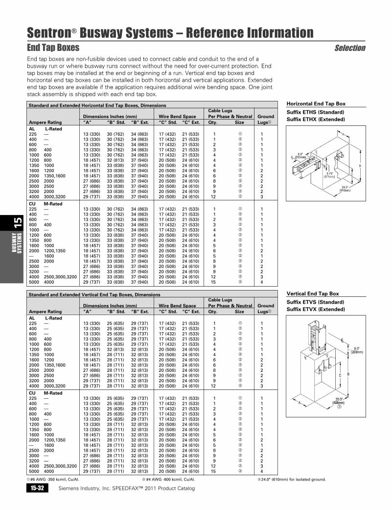
Sentron® Busway Systems – Reference InformationEnd Tap Boxes Selection
Siemens / Speedfax Previous folio: 14-33 NO Edits rev2
End tap boxes are non-fusible devices used to connect cable and conduit to the end of a busway run or where busway runs connect without the need for over-current protection. End tap boxes may be installed at the end or beginning of a run. Vertical end tap boxes and horizontal end tap boxes can be installed in both horizontal and vertical applications. Extended end tap boxes are available if the application requires additional wire bending space. One joint stack assembly is shipped with each end tap box.
a #6AWG-350kcmil,Cu/AI. b#4AWG-600kcmil,Cu/AI. c 24.0"(610mm)forisolatedground.
Standard and Extended Horizontal End Tap Boxes, Dimensions Cable Lugs Dimensions Inches (mm) Wire Bend Space Per Phase & Neutral Ground Ampere Rating “A” “B” Std. “B” Ext. “C” Std. “C” Ext. Qty. Size Lugsa
AL L-Rated 225 — 13(330) 30(762) 34(863) 17(432) 21(533) 1 a 1 400 — 13(330) 30(762) 34(863) 17(432) 21(533) 1 b 1 600 — 13(330) 30(762) 34(863) 17(432) 21(533) 2 b 1 800 400 13(330) 30(762) 34(863) 17(432) 21(533) 3 b 1 1000 600 13(330) 30(762) 34(863) 17(432) 21(533) 4 b 1 1200 800 18(457) 32(813) 37(940) 20(508) 24(610) 4 b 1 1350 1000 18(457) 33(838) 37(940) 20(508) 24(610) 4 b 1 1600 1200 18(457) 33(838) 37(940) 20(508) 24(610) 6 b 2 2000 1350,1600 18(457) 33(838) 37(940) 20(508) 24(610) 6 b 2 2500 2000 27(686) 33(838) 37(940) 20(508) 24(610) 8 b 2 3000 2500 27(686) 33(838) 37(940) 20(508) 24(610) 9 b 2 3200 2000 27(686) 33(838) 37(940) 20(508) 24(610) 9 b 2 4000 3000,3200 29(737) 33(838) 37(940) 20(508) 24(610) 12 b 3
CU M-Rated 225 — 13(330) 30(762) 34(863) 17(432) 21(533) 1 a 1 400 — 13(330) 30(762) 34(863) 17(432) 21(533) 1 b 1 600 — 13(330) 30(762) 34(863) 17(432) 21(533) 2 b 1 800 400 13(330) 30(762) 34(863) 17(432) 21(533) 3 b 1 1000 — 13(330) 30(762) 34(863) 17(432) 21(533) 4 b 1 1200 600 13(330) 33(838) 37(940) 20(508) 24(610) 4 b 1 1350 800 13(330) 33(838) 37(940) 20(508) 24(610) 4 b 1 1600 1000 18(457) 33(838) 37(940) 20(508) 24(610) 5 b 1 2000 1200,1350 18(457) 33(838) 37(940) 20(508) 24(610) 6 b 2 — 1600 18(457) 33(838) 37(940) 20(508) 24(610) 5 b 1 2500 2000 18(457) 33(838) 37(940) 20(508) 24(610) 8 b 2 3000 — 27(686) 33(838) 37(940) 20(508) 24(610) 9 b 2 3200 — 27(686) 33(838) 37(940) 20(508) 24(610) 9 b 2 4000 2500,3000,3200 27(686) 33(838) 37(940) 20(508) 24(610) 12 b 3 5000 4000 29(737) 33(838) 37(940) 20(508) 24(610) 15 b 4
Horizontal End Tap Box
Suffix ETHS (Standard) Suffix ETHX (Extended)
Standard and Extended Vertical End Tap Boxes, Dimensions Cable Lugs Dimensions Inches (mm) Wire Bend Space Per Phase & Neutral Ground Ampere Rating “A” “B” Std. “B” Ext. “C” Std. “C” Ext. Qty. Size Lugsa
AL L-Rated 225 — 13(330) 25(635) 29(737) 17(432) 21(533) 1 a 1 400 — 13(330) 25(635) 29(737) 17(432) 21(533) 1 b 1 600 — 13(330) 25(635) 29(737) 17(432) 21(533) 2 b 1 800 400 13(330) 25(635) 29(737) 17(432) 21(533) 3 b 1 1000 600 13(330) 25(635) 29(737) 17(432) 21(533) 4 b 1 1200 800 18(457) 32(813) 32(813) 20(508) 24(610) 4 b 1 1350 1000 18(457) 28(711) 32(813) 20(508) 24(610) 4 b 1 1600 1200 18(457) 28(711) 32(813) 20(508) 24(610) 6 b 2 2000 1350,1600 18(457) 28(711) 32(813) 20(508) 24(610) 6 b 2 2500 2000 27(686) 28(711) 32(813) 20(508) 24(610) 8 b 2 3000 2500 27(686) 28(711) 32(813) 20(508) 24(610) 9 b 2 3200 2000 29(737) 28(711) 32(813) 20(508) 24(610) 9 b 2 4000 3000,3200 29(737) 28(711) 32(813) 20(508) 24(610) 12 b 3
CU M-Rated 225 — 13(330) 25(635) 29(737) 17(432) 21(533) 1 a 1 400 — 13(330) 25(635) 29(737) 17(432) 21(533) 1 b 1 600 — 13(330) 25(635) 29(737) 17(432) 21(533) 2 b 1 800 400 13(330) 25(635) 29(737) 17(432) 21(533) 3 b 1 1000 — 13(330) 25(635) 29(737) 17(432) 21(533) 4 b 1 1200 600 13(330) 28(711) 32(813) 20(508) 24(610) 4 b 1 1350 800 13(330) 28(711) 32(813) 20(508) 24(610) 4 b 1 1600 1000 18(457) 28(711) 32(813) 20(508) 24(610) 5 b 1 2000 1200,1350 18(457) 28(711) 32(813) 20(508) 24(610) 6 b 2 — 1600 18(457) 28(711) 32(813) 20(508) 24(610) 5 b 1 2500 2000 18(457) 28(711) 32(813) 20(508) 24(610) 8 b 2 3000 — 27(686) 28(711) 32(813) 20(508) 24(610) 9 b 2 3200 — 27(686) 28(711) 32(813) 20(508) 24(610) 9 b 2 4000 2500,3000,3200 27(686) 28(711) 32(813) 20(508) 24(610) 12 b 3 5000 4000 29(737) 28(711) 32(813) 20(508) 24(610) 15 b 4
Vertical End Tap Box
Suffix ETVS (Standard) Suffix ETVX (Extended)
Siemens Industry, Inc. SPEEDFAX™ 2011 Product Catalog 15-33
15BUSW
AY SYSTEM
S
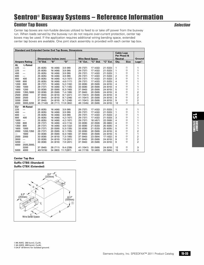
Sentron® Busway Systems – Reference InformationCenter Tap Boxes Selection
Siemens / Speedfax Previous folio: 14-34 SS 2/13/11
Standard and Extended Center End Tap Boxes, Dimensions Cable Lugs Per Phase & Dimensions Inches (mm) Wire Bend Space Neutral Ground Ampere Rating “A”Std. “B” “D” “A” Ext.. “C” Std. “C” Ext. Qty. Size Lugsa
AL L-Rated 225 — 25(635) 16(406) 3.9(99) 29(737) 17(432) 21(533) 1 a 1 225 — 25(635) 16(406) 3.9(99) 29(737) 17(432) 21(533) 1 b 1 400 — 25(635) 16(406) 3.9(99) 29(737) 17(432) 21(533) 1 b 1 600 — 25(635) 16(406) 3.9(99) 29(737) 17(432) 21(533) 2 b 1 800 400 25(635) 16(406) 4.2(107) 29(737) 17(432) 21(533) 3 b 1 1000 600 25(635) 16(406) 4.6(117) 29(737) 17(432) 21(533) 4 b 1 1200 800 29(737) 16(406) 5.2(132) 33(838) 20(508) 24(610) 4 b 1 1350 1000 29(737) 16(406) 5.7(145) 33(838) 20(508) 24(610) 4 b 1 1600 1200 33(838) 20(508) 6.3(160) 37(940) 20(508) 24(610) 5 b 1 2000 1350,1600 33(838) 20(508) 7.4(188) 37(940) 20(508) 24(610) 6 b 2 2500 2000 37(940) 24(610) 8.7(221) 41(1041) 20(508) 24(610) 8 b 2 3000 2500 37(940) 24(610) 9.7(246) 41(1041) 20(508) 24(610) 9 b 2 3200 2000 37(940) 24(610) 9.7(246) 41(1041) 20(508) 24(610) 9 b 2 4000 3000,3200 45(1143) 28(711)11.9(302) 49(1245) 20(508) 24(610) 12 b 3
CU M-Rated 225 — 25(635) 16(406) 3.9(99) 29(737) 17(432) 21(533) 1 b 1 400 — 25(635) 16(406) 3.9(99) 29(737) 17(432) 21(533) 1 b 1 600 — 25(635) 16(406) 3.9(99) 29(737) 17(432) 21(533) 2 b 1 800 400 25(635) 16(406) 4.2(107) 29(737) 17(432) 21(533) 3 b 1 1000 — 25(635) 16(406) 4.2(107) 29(737) 18(457) 22(559) 4 b 1 1200 600 29(737) 16(406) 4.5(114) 33(838) 22(559) 26(660) 4 b 1 1350 800 29(737) 16(406) 4.8(122) 33(838) 21(533) 25(635) 4 b 1 1600 1000 29(737) 20(508) 5.3(135) 33(838) 21(533) 25(635) 5 b 1 2000 1200,1350 29(737) 20(508) 6.1(155) 33(838) 20(508) 24(610) 6 b 2 — 1600 33(838) 20(508) 6.3(160) 37(940) 20(508) 24(610) 5 b 1 2500 2000 33(838) 24(610) 7.3(185) 37(940) 23(584) 17(432) 8 b 2 3000 — 33(838) 24(610) 7.9(201) 37(940) 20(508) 24(610) 9 b 2 3200 — 33(838) 24(610) 7.9(201) 37(940) 20(508) 24(610) 9 b 2 4000 2500,3000, 3200 37(940) 28(711) 9.4(239) 41(1041) 20(508) 24(610) 12 b 3 5000 4000 40(1016) 34(863) 11.7(297) 44(1118) 19(483) 23(584) 15 b 4
Center tap boxes are non-fusible devices utilized to feed to or take off power from the busway run. When loads served by the busway run do not require over-current protection, center tap boxes may be used. If the application requires additional wiring bending space, extended center tap boxes are available. One joint stack assembly is provided with each center tap box.
a #6AWG-350kcmil,Cu/AI.b#4AWG-600kcmil,Cu/AI.c 24.0"(610mm)forisolatedground.
Center Tap Box
Suffix CTBS (Standard) Suffix CTBX (Extended)
Siemens Industry, Inc. SPEEDFAX™ 2011 Product Catalog15-34
15BU
SWAY
SY
STEM
S
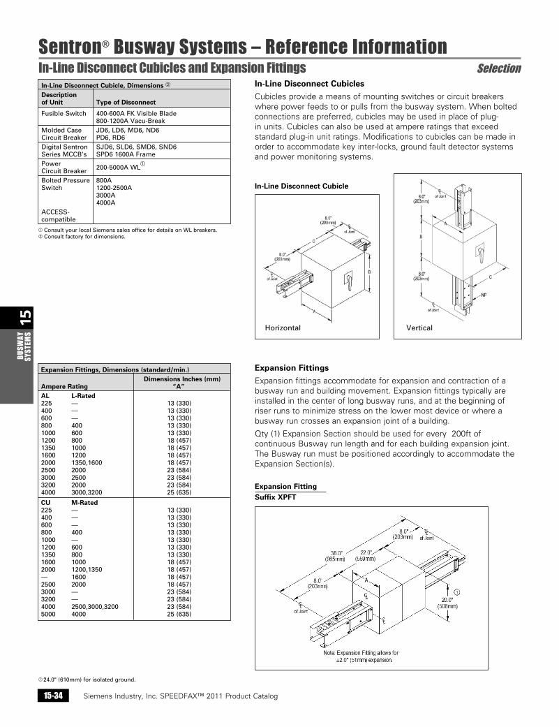
Sentron® Busway Systems – Reference InformationIn-Line Disconnect Cubicles and Expansion Fittings Selection
Siemens / Speedfax Previous folio: 14-35 SS 2/13/11
In-Line Disconnect Cubicles
Cubicles provide a means of mounting switches or circuit breakers where power feeds to or pulls from the busway system. When bolted connections are preferred, cubicles may be used in place of plug-in units. Cubicles can also be used at ampere ratings that exceed standard plug-in unit ratings. Modifications to cubicles can be made in order to accommodate key inter-locks, ground fault detector systems and power monitoring systems.
Expansion Fittings
Expansion fittings accommodate for expansion and contraction of a busway run and building movement. Expansion fittings typically are installed in the center of long busway runs, and at the beginning of riser runs to minimize stress on the lower most device or where a busway run crosses an expansion joint of a building.
Qty (1) Expansion Section should be used for every 200ft of continuous Busway run length and for each building expansion joint. The Busway run must be positioned accordingly to accommodate the Expansion Section(s).
In-Line Disconnect Cubicle
Expansion FittingSuffix XPFT
In-Line Disconnect Cubicle, Dimensions b
Description of Unit Type of Disconnect
FusibleSwitch 400-600AFKVisibleBlade 800-1200AVacu-Break MoldedCase JD6,LD6,MD6,ND6 CircuitBreaker PD6,RD6 DigitalSentron SJD6,SLD6,SMD6,SND6 SeriesMCCB’s SPD61600AFrame Power 200-5000AWL
a
CircuitBreaker BoltedPressure 800A Switch 1200-2500A 3000A 4000A ACCESS- compatible
Expansion Fittings, Dimensions (standard/min.) Dimensions Inches (mm) Ampere Rating “A” AL L-Rated 225 — 13(330) 400 — 13(330) 600 — 13(330) 800 400 13(330) 1000 600 13(330) 1200 800 18(457) 1350 1000 18(457) 1600 1200 18(457) 2000 1350,1600 18(457) 2500 2000 23(584) 3000 2500 23(584) 3200 2000 23(584) 4000 3000,3200 25(635)
CU M-Rated 225 — 13(330) 400 — 13(330) 600 — 13(330) 800 400 13(330) 1000 — 13(330) 1200 600 13(330) 1350 800 13(330) 1600 1000 18(457) 2000 1200,1350 18(457) — 1600 18(457) 2500 2000 18(457) 3000 — 23(584) 3200 — 23(584) 4000 2500,3000,3200 23(584) 5000 4000 25(635)
a 24.0"(610mm)forisolatedground.
aConsultyourlocalSiemenssalesofficefordetailsonWLbreakers.bConsultfactoryfordimensions.
Horizontal Vertical
Siemens Industry, Inc. SPEEDFAX™ 2011 Product Catalog 15-35
15BUSW
AY SYSTEM
S
Sentron® Busway Systems – Reference InformationReducers and Phase Rotation Fittings Selection
Siemens / Speedfax Previous folio: 14-36 SS 2/13/11
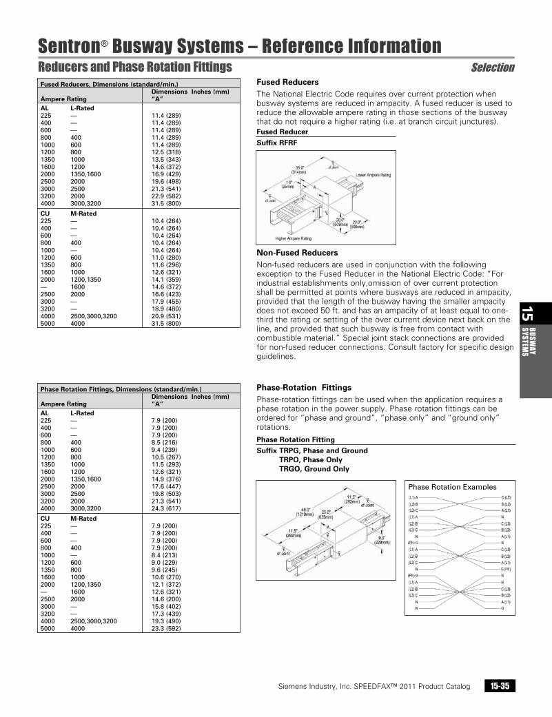
Fused Reducers The National Electric Code requires over current protection when busway systems are reduced in ampacity. A fused reducer is used to reduce the allowable ampere rating in those sections of the busway that do not require a higher rating (i.e. at branch circuit junctures).
Non-Fused Reducers Non-fused reducers are used in conjunction with the following exception to the Fused Reducer in the National Electric Code: “For industrial establishments only,omission of over current protection shall be permitted at points where busways are reduced in ampacity, provided that the length of the busway having the smaller ampacity does not exceed 50 ft. and has an ampacity of at least equal to one-third the rating or setting of the over current device next back on the line, and provided that such busway is free from contact with combustible material.” Special joint stack connections are provided for non-fused reducer connections. Consult factory for specific design guidelines.
Phase-Rotation FittingsPhase-rotation fittings can be used when the application requires a phase rotation in the power supply. Phase rotation fittings can be ordered for “phase and ground”, “phase only” and “ground only” rotations.
Fused ReducerSuffix RFRF
Phase Rotation FittingSuffix TRPG, Phase and Ground
TRPO, Phase Only TRGO, Ground Only
Fused Reducers, Dimensions (standard/min.) Dimensions Inches (mm) Ampere Rating “A” AL L-Rated 225 — 11.4(289) 400 — 11.4(289) 600 — 11.4(289) 800 400 11.4(289) 1000 600 11.4(289) 1200 800 12.5(318) 1350 1000 13.5(343) 1600 1200 14.6(372) 2000 1350,1600 16.9(429) 2500 2000 19.6(498) 3000 2500 21.3(541) 3200 2000 22.9(582) 4000 3000,3200 31.5(800)
CU M-Rated 225 — 10.4(264) 400 — 10.4(264) 600 — 10.4(264) 800 400 10.4(264) 1000 — 10.4(264) 1200 600 11.0(280) 1350 800 11.6(296) 1600 1000 12.6(321) 2000 1200,1350 14.1(359) — 1600 14.6(372) 2500 2000 16.6(423) 3000 — 17.9(455) 3200 — 18.9(480) 4000 2500,3000,3200 20.9(531) 5000 4000 31.5(800)
Phase Rotation Fittings, Dimensions (standard/min.) Dimensions Inches (mm) Ampere Rating “A” AL L-Rated 225 — 7.9(200) 400 — 7.9(200) 600 — 7.9(200) 800 400 8.5(216) 1000 600 9.4(239) 1200 800 10.5(267) 1350 1000 11.5(293) 1600 1200 12.6(321) 2000 1350,1600 14.9(376) 2500 2000 17.6(447) 3000 2500 19.8(503) 3200 2000 21.3(541) 4000 3000,3200 24.3(617)
CU M-Rated 225 — 7.9(200) 400 — 7.9(200) 600 — 7.9(200) 800 400 7.9(200) 1000 — 8.4(213) 1200 600 9.0(229) 1350 800 9.6(245) 1600 1000 10.6(270) 2000 1200,1350 12.1(372) — 1600 12.6(321) 2500 2000 14.6(200) 3000 — 15.8(402) 3200 — 17.3(439) 4000 2500,3000,3200 19.3(490) 5000 4000 23.3(592)
PhaseRotationExamples
Siemens Industry, Inc. SPEEDFAX™ 2011 Product Catalog15-36
15BU
SWAY
SY
STEM
S
Sentron® Busway Systems – Reference InformationService Heads Selection
Siemens / Speedfax Previous folio: 14-37 NO Edits rev2
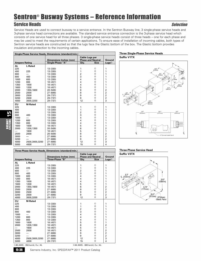
Three-Phase Service Heads, Dimensions (standard/min.) Cable Lugs per Dimensions Inches (mm) Phase and Neutral Ground Ampere Rating Three-Phase “B” Qty. Size Lugsa
AL L-Rated 225 13(330) 1 a 1 400 225 13(330) 1 b 1 600 — 13(330) 2 b 1 800 400 13(330) 3 b 1 1000 600 13(330) 4 b 1 1200 800 18(457) 4 b 1 1350 1000 18(457) 4 b 1 1600 1200 18(457) 5 b 1 2000 1350,1600 18(457) 6 b 2 2500 2000 27(686) 8 b 2 3000 2500 27(686) 9 b 2 3200 2000 27(686) 9 b 2 4000 3000,3200 29(737) 12 b 3
CU M-Rated 225 13(330) 1 a 1 400 13(330) 1 b 1 600 13(330) 2 b 1 800 400 13(330) 3 b 1 1000 — 13(330) 4 b 1 1200 600 13(330) 4 b 1 1350 800 13(330) 4 b 1 1600 1000 18(457) 5 b 1 2000 1200,1350 18(457) 6 b 2 — 1600 18(457) 5 b 1 2500 2000 18(457) 8 b 2 3000 — 27(686) 9 b 2 3200 — 27(686) 9 b 2 4000 2500,3000,3200 27(686) 12 b 3 5000 4000 29(737) 15 b 4a #6AWG-350kcmil,Cu/Al. b #4AWG-600kcmil,Cu/Al.
Single-Phase Service Heads, Dimensions (standard/min.) Cable Lugs per Dimensions Inches (mm) Phase and Neutral Ground Ampere Rating Single-Phase “A” Qty. Size Lugsa
AL L-Rated 225 13(330) 1 a 1 400 225 13(330) 1 b 1 600 — 13(330) 2 b 1 800 400 13(330) 3 b 1 1000 600 13(330) 4 b 1 1200 800 18(457) 4 b 1 1350 1000 18(457) 4 b 1 1600 1200 18(457) 5 b 1 2000 1350,1600 20(508) 6 b 2 2500 2000 27(686) 8 b 2 3000 2500 29(737) 9 b 2 3200 2000 29(737) 9 b 2 4000 3000,3200 29(737) 12 b 3
CU M-Rated 225 13(330) 1 a 1 400 13(330) 1 b 1 600 13(330) 2 b 1 800 400 13(330) 3 b 1 1000 — 13(330) 4 b 1 1200 600 13(330) 4 b 1 1350 800 13(330) 4 b 1 1600 1000 18(457) 5 b 1 2000 1200,1350 20(508) 6 b 2 — 1600 18(457) 5 b 1 2500 2000 20(508) 8 b 2 3000 — 27(686) 9 b 2 3200 — 27(686) 9 b 2 4000 2500,3000,3200 27(686) 12 b 3 5000 4000 29(737) 15 b 4
Service Heads are used to connect busway to a service entrance. In the Sentron Busway line, 3 single-phase service heads and 3-phase service head connections are available. The standard service entrance connection is the 3-phase service head which consists of one service head for all three phases. 3 single-phase service heads consist of three heads – one for each phase and may be used to meet the requirements of certain applications. To ensure ease of installation of incoming cables, both types of Sentron service heads are constructed so that the lugs face the Glastic bottom of the box. The Glastic bottom provides insulation and protection to the incoming cables.
Three-Phase Service HeadSuffix V3TX
Three Single-Phase Service HeadsSuffix V1TX
Siemens Industry, Inc. SPEEDFAX™ 2011 Product Catalog 15-37
15BUSW
AY SYSTEM
S
Sentron® Busway Systems – Reference InformationHangers Selection
Siemens / Speedfax Previous folio: 14-38 NO Edits rev2
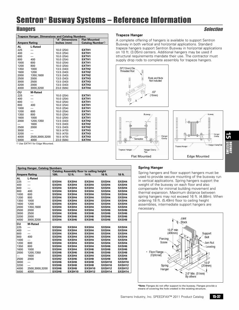
Trapeze HangerA complete offering of hangers is available to support Sentron Busway in both vertical and horizontal applications. Standard trapeze hangers support Sentron Busway in horizontal applications on 10 ft. (3.05m) centers. Additional hangers may be used if structural requirements mandate their use. The contractor must supply drop rods to complete assembly for trapeze hangers.
Spring Hanger, Catalog Numbers Catalog Assembly floor to ceiling height Ampere Rating 10ft. 12 ft. 14 ft. 16 ft. 18 ft. AL L-Rated225 — SXSH4 SXSH4 SXSH4 SXSH4 SXSH4400 — SXSH4 SXSH4 SXSH4 SXSH4 SXSH4600 — SXSH4 SXSH4 SXSH4 SXSH4 SXSH4800 400 SXSH4 SXSH4 SXSH4 SXSH4 SXSH41000 600 SXSH4 SXSH4 SXSH4 SXSH4 SXSH41200 800 SXSH4 SXSH4 SXSH4 SXSH4 SXSH41350 1000 SXSH4 SXSH4 SXSH4 SXSH4 SXSH41600 1200 SXSH4 SXSH4 SXSH4 SXSH4 SXSH42000 1350,1600 SXSH4 SXSH4 SXSH4 SXSH4 SXSH42500 2000 SXSH4 SXSH4 SXSH4 SXSH6 SXSH63000 2500 SXSH4 SXSH6 SXSH6 SXSH6 SXSH63200 2000 SXSH4 SXSH6 SXSH6 SXSH6 SXSH64000 3000,3200 SXSH4 SXSH6 SXSH6 SXSH6 SXSH8
CU M-Rated225 — SXSH4 SXSH4 SXSH4 SXSH4 SXSH4400 — SXSH4 SXSH4 SXSH4 SXSH4 SXSH4600 — SXSH4 SXSH4 SXSH4 SXSH4 SXSH4800 400 SXSH4 SXSH4 SXSH4 SXSH4 SXSH41000 — SXSH4 SXSH4 SXSH4 SXSH4 SXSH41200 600 SXSH4 SXSH4 SXSH4 SXSH4 SXSH41350 800 SXSH4 SXSH4 SXSH4 SXSH6 SXSH61600 1000 SXSH4 SXSH4 SXSH6 SXSH6 SXSH62000 1200,1350 SXSH6 SXSH6 SXSH6 SXSH6 SXSH8— 1600 SXSH4 SXSH4 SXSH4 SXSH4 SXSH42500 2000 SXSH2 SXSH6 SXSH8 SXSH8 SXSH83000 — SXSH6 SXSH8 SXSH8 SXSH10 SXSH103200 — SXSH6 SXSH8 SXSH8 SXSH10 SXSH124000 2500,3000,3200 SXSH6 SXSH8 SXSH10 SXSH12 SXSH125000 4000 SXSH6 SXSH10 SXSH12 SXSH14 SXSH14
Trapeze Hanger, Dimensions and Catalog Numbers “A” Dimensions Flat Mounted Ampere Rating Inches (mm) Catalog Numbera
AL L-Rated 225 — 10.0(254) SXTH1 400 — 10.0(254) SXTH1 600 — 10.0(254) SXTH1 800 400 10.0(254) SXTH1 1000 600 10.0(254) SXTH1 1200 800 10.0(254) SXTH1 1350 1000 13.5(343) SXTH2 1600 1200 13.5(343) SXTH2 2000 1350,1600 13.5(343) SXTH2 2500 2000 13.5(343) SXTH3 3000 2500 13.5(343) SXTH3 3200 2000 13.5(343) SXTH3 4000 3000,3200 23.0(584) SXTH4
CU M-Rated 225 — 10.0(254) SXTH1 400 — 10.0(254) SXTH1 600 — 10.0(254) SXTH1 800 400 10.0(254) SXTH1 1000 — 10.0(254) SXTH1 1200 600 10.0(254) SXTH1 1350 800 10.0(254) SXTH1 1600 1000 10.0(254) SXTH1 2000 1200,1350 13.5(343) SXTH2 — 1600 13.5(343) SXTH2 2500 2000 13.5(343) SXTH2 3000 — 18.5(470) SXTH3 3200 — 18.5(470) SXTH3 4000 2500,3000,3200 18.5(470) SXTH3 5000 4000 23.0(584) SXTH4
Spring HangerSpring hangers and floor support hangers must be used to provide secure mounting of the busway run in vertical applications. Spring hangers support the weight of the busway on each floor and also compensate for minimal building movement and thermal expansion. Maximum distance between spring hangers may not exceed 16 ft. (4.88m). When ordering 18 ft. (5.49m) floor to ceiling height assemblies, intermediate support hangers are necessary.
aUseSXTH1forEdgeMounted.
*Note:Flangesdonotoffersupporttothebusway.Flangesprovideameansofcoveringtheholecreatedintheexistingstructure.
FlatMounted EdgeMounted
*
Siemens Industry, Inc. SPEEDFAX™ 2011 Product Catalog15-38
15BU
SWAY
SY
STEM
S
Sentron® Busway Systems – Reference InformationHangers Selection
Siemens / Speedfax Previous folio: 14-39 SS 2/13/11
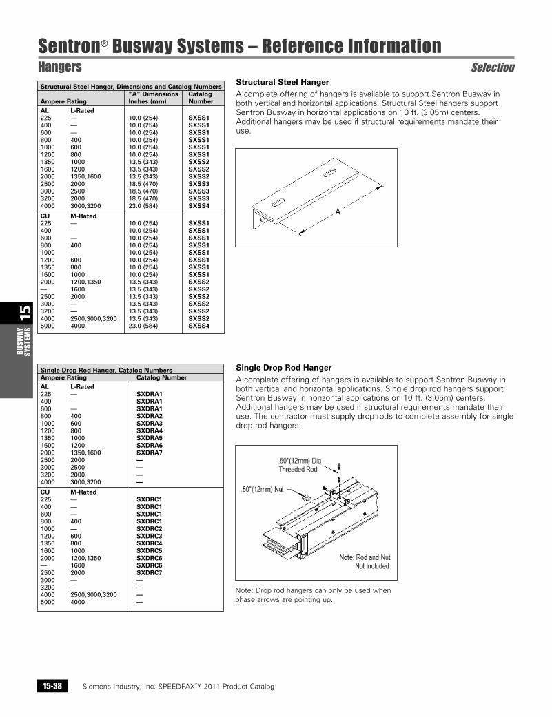
Single Drop Rod Hanger, Catalog Numbers Ampere Rating Catalog Number AL L-Rated 225 — SXDRA1 400 — SXDRA1 600 — SXDRA1 800 400 SXDRA2 1000 600 SXDRA3 1200 800 SXDRA4 1350 1000 SXDRA5 1600 1200 SXDRA6 2000 1350,1600 SXDRA7 2500 2000 — 3000 2500 — 3200 2000 — 4000 3000,3200 —
CU M-Rated 225 — SXDRC1 400 — SXDRC1 600 — SXDRC1 800 400 SXDRC1 1000 — SXDRC2 1200 600 SXDRC3 1350 800 SXDRC4 1600 1000 SXDRC5 2000 1200,1350 SXDRC6 — 1600 SXDRC6 2500 2000 SXDRC7 3000 — — 3200 — — 4000 2500,3000,3200 — 5000 4000 —
Structural Steel Hanger A complete offering of hangers is available to support Sentron Busway in both vertical and horizontal applications. Structural Steel hangers support Sentron Busway in horizontal applications on 10 ft. (3.05m) centers. Additional hangers may be used if structural requirements mandate their use.
Single Drop Rod HangerA complete offering of hangers is available to support Sentron Busway in both vertical and horizontal applications. Single drop rod hangers support Sentron Busway in horizontal applications on 10 ft. (3.05m) centers. Additional hangers may be used if structural requirements mandate their use. The contractor must supply drop rods to complete assembly for single drop rod hangers.
Structural Steel Hanger, Dimensions and Catalog Numbers “A” Dimensions Catalog Ampere Rating Inches (mm) Number AL L-Rated 225 — 10.0(254) SXSS1 400 — 10.0(254) SXSS1 600 — 10.0(254) SXSS1 800 400 10.0(254) SXSS1 1000 600 10.0(254) SXSS1 1200 800 10.0(254) SXSS1 1350 1000 13.5(343) SXSS2 1600 1200 13.5(343) SXSS2 2000 1350,1600 13.5(343) SXSS2 2500 2000 18.5(470) SXSS3 3000 2500 18.5(470) SXSS3 3200 2000 18.5(470) SXSS3 4000 3000,3200 23.0(584) SXSS4
CU M-Rated 225 — 10.0(254) SXSS1 400 — 10.0(254) SXSS1 600 — 10.0(254) SXSS1 800 400 10.0(254) SXSS1 1000 — 10.0(254) SXSS1 1200 600 10.0(254) SXSS1 1350 800 10.0(254) SXSS1 1600 1000 10.0(254) SXSS1 2000 1200,1350 13.5(343) SXSS2 — 1600 13.5(343) SXSS2 2500 2000 13.5(343) SXSS2 3000 — 13.5(343) SXSS2 3200 — 13.5(343) SXSS2 4000 2500,3000,3200 13.5(343) SXSS2 5000 4000 23.0(584) SXSS4
Note: Drop rod hangers can only be used when phase arrows are pointing up.
Siemens Industry, Inc. SPEEDFAX™ 2011 Product Catalog 15-39
15BUSW
AY SYSTEM
S
Sentron® Busway Systems – Reference InformationHangers and End Closers Selection
Siemens / Speedfax Previous folio: 14-40 NO Edits rev2
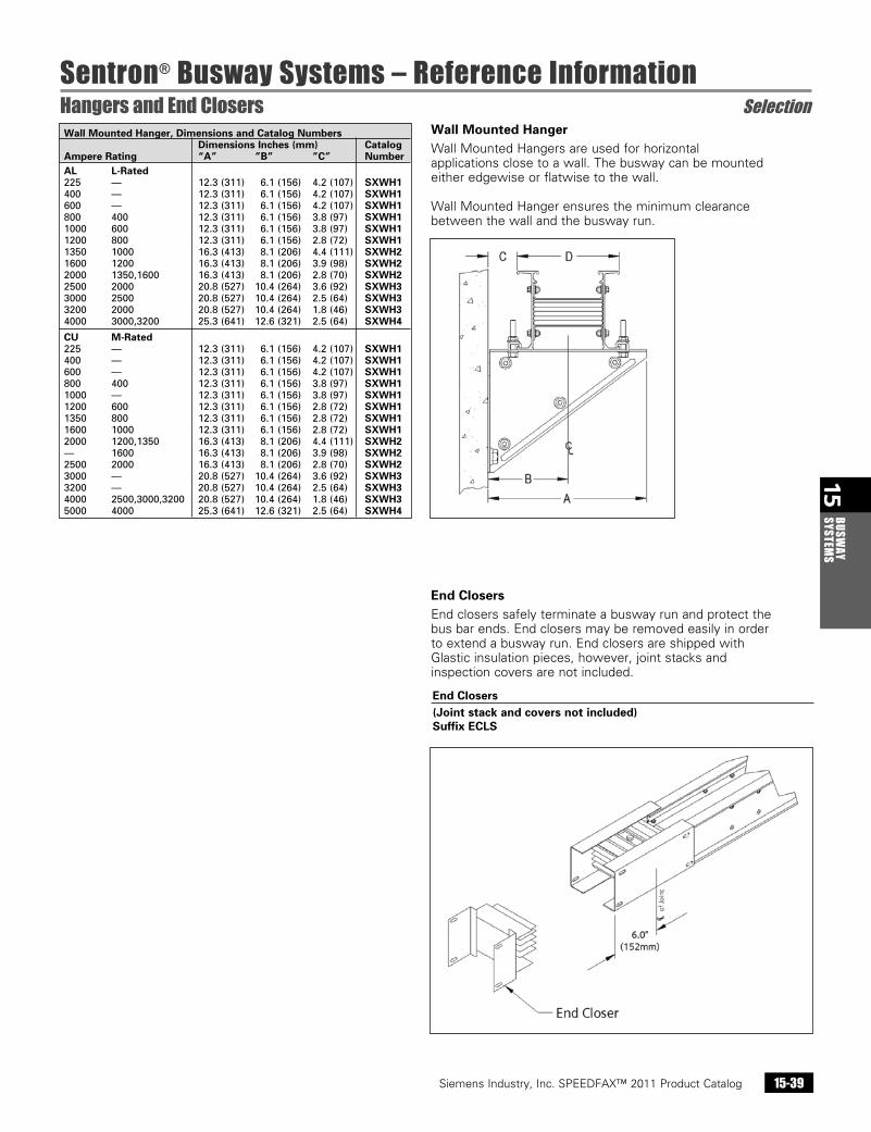
End ClosersEnd closers safely terminate a busway run and protect the bus bar ends. End closers may be removed easily in order to extend a busway run. End closers are shipped with Glastic insulation pieces, however, joint stacks and inspection covers are not included.
Wall Mounted HangerWall Mounted Hangers are used for horizontal applications close to a wall. The busway can be mounted either edgewise or flatwise to the wall.
Wall Mounted Hanger ensures the minimum clearance between the wall and the busway run.
End Closers(Joint stack and covers not included)Suffix ECLS
Wall Mounted Hanger, Dimensions and Catalog Numbers Dimensions Inches (mm) Catalog Ampere Rating “A” ”B” ”C” Number AL L-Rated 225 — 12.3(311) 6.1(156) 4.2(107) SXWH1 400 — 12.3(311) 6.1(156) 4.2(107) SXWH1 600 — 12.3(311) 6.1(156) 4.2(107) SXWH1 800 400 12.3(311) 6.1(156) 3.8(97) SXWH1 1000 600 12.3(311) 6.1(156) 3.8(97) SXWH1 1200 800 12.3(311) 6.1(156) 2.8(72) SXWH1 1350 1000 16.3(413) 8.1(206) 4.4(111) SXWH2 1600 1200 16.3(413) 8.1(206) 3.9(98) SXWH2 2000 1350,1600 16.3(413) 8.1(206) 2.8(70) SXWH2 2500 2000 20.8(527) 10.4(264) 3.6(92) SXWH3 3000 2500 20.8(527) 10.4(264) 2.5(64) SXWH3 3200 2000 20.8(527) 10.4(264) 1.8(46) SXWH3 4000 3000,3200 25.3(641) 12.6(321) 2.5(64) SXWH4
CU M-Rated 225 — 12.3(311) 6.1(156) 4.2(107) SXWH1 400 — 12.3(311) 6.1(156) 4.2(107) SXWH1 600 — 12.3(311) 6.1(156) 4.2(107) SXWH1 800 400 12.3(311) 6.1(156) 3.8(97) SXWH1 1000 — 12.3(311) 6.1(156) 3.8(97) SXWH1 1200 600 12.3(311) 6.1(156) 2.8(72) SXWH1 1350 800 12.3(311) 6.1(156) 2.8(72) SXWH1 1600 1000 12.3(311) 6.1(156) 2.8(72) SXWH1 2000 1200,1350 16.3(413) 8.1(206) 4.4(111) SXWH2 — 1600 16.3(413) 8.1(206) 3.9(98) SXWH2 2500 2000 16.3(413) 8.1(206) 2.8(70) SXWH2 3000 — 20.8(527) 10.4(264) 3.6(92) SXWH3 3200 — 20.8(527) 10.4(264) 2.5(64) SXWH3 4000 2500,3000,3200 20.8(527) 10.4(264) 1.8(46) SXWH3 5000 4000 25.3(641) 12.6(321) 2.5(64) SXWH4
Siemens Industry, Inc. SPEEDFAX™ 2011 Product Catalog15-40
15BU
SWAY
SY
STEM
S
Sentron® Busway Systems – Reference InformationRoof and Wall Flanges Selection
Siemens / Speedfax Previous folio: 14-41 NO Edits rev2
Wall, Ceiling and Floor Flanges, Dimensions Dimensions Inches (mm) Ampere Rating “A” ”B” AL L-Rated 225 — 11(279) 7(178) 400 — 11(279) 7(178) 600 — 11(279) 7(178) 800 400 11(279) 7(178) 1000 600 12(305) 8(203) 1200 800 13(330) 9(229) 1350 1000 14(356) 10(254) 1600 1200 15(381) 11(279) 2000 1350,1600 17(432) 13(330) 2500 2000 20(508) 16(406) 3000 2500 22(559) 18(457) 3200 2000 24(610) 20(508) 4000 3000,3200 26(660) 22(559)
CU M-Rated 225 — 10(254) 6(152) 400 — 10(254) 6(152) 600 — 10(254) 6(152) 800 400 10(254) 6(152) 1000 — 11(279) 7(178) 1200 600 12(305) 8(203) 1350 800 12(305) 8(203) 1600 1000 13(330) 9(229) 2000 1200,1350 15(381) 11(279) — 1600 15(381) 11(279) 2500 2000 17(432) 13(330) 3000 — 18(457) 14(356) 3200 — 19(483) 15(381) 4000 2500,3000,3200 21(533) 17(432) 5000 4000 26(660) 22(559)
Wall, Ceiling and Floor FlangesSuffix GWFL
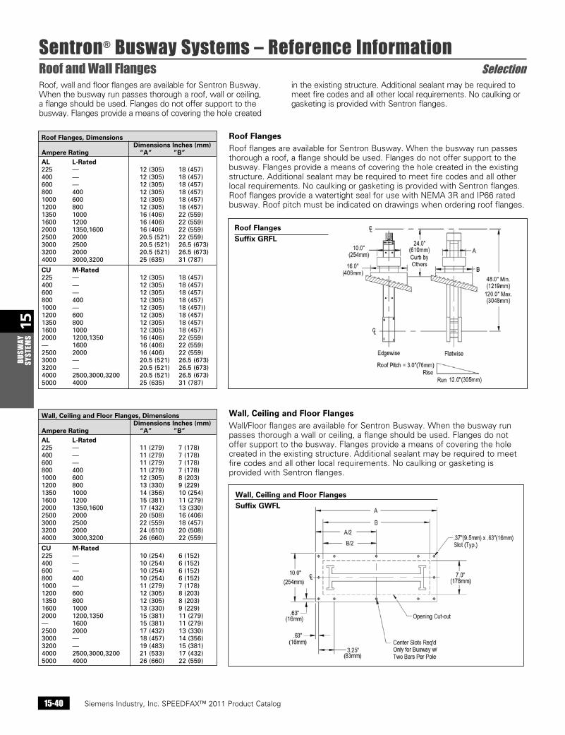
Wall, Ceiling and Floor FlangesWall/Floor flanges are available for Sentron Busway. When the busway run passes thorough a wall or ceiling, a flange should be used. Flanges do not offer support to the busway. Flanges provide a means of covering the hole created in the existing structure. Additional sealant may be required to meet fire codes and all other local requirements. No caulking or gasketing is provided with Sentron flanges.
Roof FlangesSuffix GRFL
Roof FlangesRoof flanges are available for Sentron Busway. When the busway run passes thorough a roof, a flange should be used. Flanges do not offer support to the busway. Flanges provide a means of covering the hole created in the existing structure. Additional sealant may be required to meet fire codes and all other local requirements. No caulking or gasketing is provided with Sentron flanges. Roof flanges provide a watertight seal for use with NEMA 3R and IP66 rated busway. Roof pitch must be indicated on drawings when ordering roof flanges.
Roof Flanges, Dimensions Dimensions Inches (mm) Ampere Rating “A” ”B” AL L-Rated 225 — 12(305) 18(457) 400 — 12(305) 18(457) 600 — 12(305) 18(457) 800 400 12(305) 18(457) 1000 600 12(305) 18(457) 1200 800 12(305) 18(457) 1350 1000 16(406) 22(559) 1600 1200 16(406) 22(559) 2000 1350,1600 16(406) 22(559) 2500 2000 20.5(521) 22(559) 3000 2500 20.5(521) 26.5(673) 3200 2000 20.5(521) 26.5(673) 4000 3000,3200 25(635) 31(787)
CU M-Rated 225 — 12(305) 18(457) 400 — 12(305) 18(457) 600 — 12(305) 18(457) 800 400 12(305) 18(457) 1000 — 12(305) 18(457)) 1200 600 12(305) 18(457) 1350 800 12(305) 18(457) 1600 1000 12(305) 18(457) 2000 1200,1350 16(406) 22(559) — 1600 16(406) 22(559) 2500 2000 16(406) 22(559) 3000 — 20.5(521) 26.5(673) 3200 — 20.5(521) 26.5(673) 4000 2500,3000,3200 20.5(521) 26.5(673) 5000 4000 25(635) 31(787)
Roof, wall and floor flanges are available for Sentron Busway. When the busway run passes thorough a roof, wall or ceiling, a flange should be used. Flanges do not offer support to the busway. Flanges provide a means of covering the hole created
in the existing structure. Additional sealant may be required to meet fire codes and all other local requirements. No caulking or gasketing is provided with Sentron flanges.
Siemens Industry, Inc. SPEEDFAX™ 2011 Product Catalog 15-41
15BUSW
AY SYSTEM
S
Sentron® Busway Systems – Reference InformationFlanged Ends Selection
Siemens / Speedfax Previous folio: 14-42 SS 2/13/11
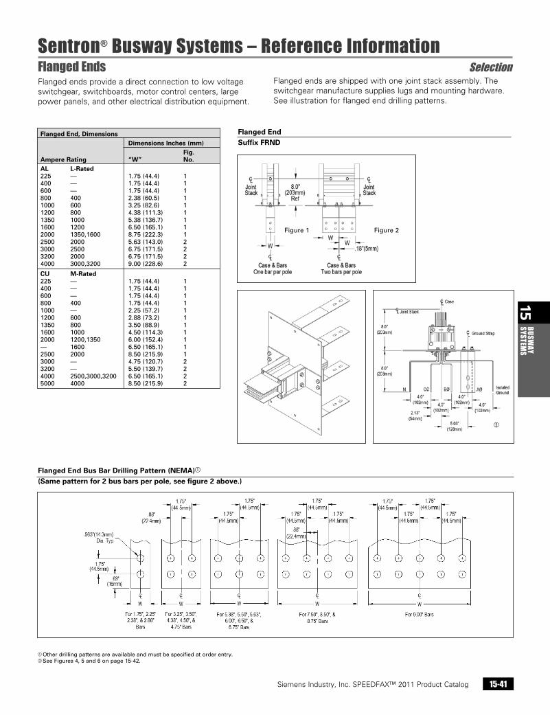
Flanged ends provide a direct connection to low voltage switchgear, switchboards, motor control centers, large power panels, and other electrical distribution equipment.
Flanged EndSuffix FRND
Flanged End Bus Bar Drilling Pattern (NEMA)a
(Same pattern for 2 bus bars per pole, see figure 2 above.)
a Otherdrillingpatternsareavailableandmustbespecifiedatorderentry.b SeeFigures4,5and6onpage15-42.
Flanged End, Dimensions Dimensions Inches (mm) Fig. Ampere Rating “W” No. AL L-Rated 225 — 1.75(44.4) 1 400 — 1.75(44.4) 1 600 — 1.75(44.4) 1 800 400 2.38(60.5) 1 1000 600 3.25(82.6) 1 1200 800 4.38(111.3) 1 1350 1000 5.38(136.7) 1 1600 1200 6.50(165.1) 1 2000 1350,1600 8.75(222.3) 1 2500 2000 5.63(143.0) 2 3000 2500 6.75(171.5) 2 3200 2000 6.75(171.5) 2 4000 3000,3200 9.00(228.6) 2
CU M-Rated 225 — 1.75(44.4) 1 400 — 1.75(44.4) 1 600 — 1.75(44.4) 1 800 400 1.75(44.4) 1 1000 — 2.25(57.2) 1 1200 600 2.88(73.2) 1 1350 800 3.50(88.9) 1 1600 1000 4.50(114.3) 1 2000 1200,1350 6.00(152.4) 1 — 1600 6.50(165.1) 1 2500 2000 8.50(215.9) 1 3000 — 4.75(120.7) 2 3200 — 5.50(139.7) 2 4000 2500,3000,3200 6.50(165.1) 2 5000 4000 8.50(215.9) 2
Figure1 Figure2
b
Flanged ends are shipped with one joint stack assembly. The switchgear manufacture supplies lugs and mounting hardware. See illustration for flanged end drilling patterns.
Siemens Industry, Inc. SPEEDFAX™ 2011 Product Catalog15-42
15BU
SWAY
SY
STEM
S
Sentron® Busway Systems – Reference InformationFlanged Ends Selection
Siemens / Speedfax Previous folio: 14-43 SS 2/13/11
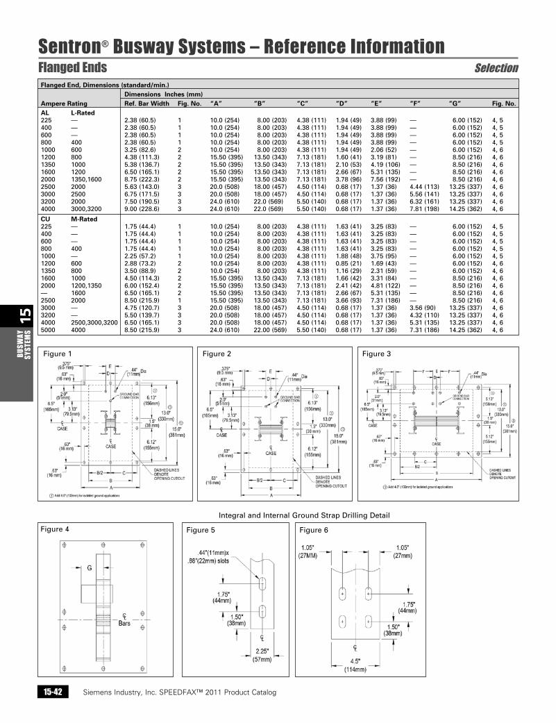
Flanged End, Dimensions (standard/min.) Dimensions Inches (mm) Ampere Rating Ref. Bar Width Fig. No. “A” ”B” ”C” ”D” ”E” ”F” ”G” Fig. No. AL L-Rated 225 — 2.38(60.5) 1 10.0(254) 8.00(203) 4.38(111) 1.94(49) 3.88(99) — 6.00(152) 4,5 400 — 2.38(60.5) 1 10.0(254) 8.00(203) 4.38(111) 1.94(49) 3.88(99) — 6.00(152) 4,5 600 — 2.38(60.5) 1 10.0(254) 8.00(203) 4.38(111) 1.94(49) 3.88(99) — 6.00(152) 4,5 800 400 2.38(60.5) 1 10.0(254) 8.00(203) 4.38(111) 1.94(49) 3.88(99) — 6.00(152) 4,5 1000 600 3.25(82.6) 2 10.0(254) 8.00(203) 4.38(111) 1.94(49) 2.06(52) — 6.00(152) 4,6 1200 800 4.38(111.3) 2 15.50(395) 13.50(343) 7.13(181) 1.60(41) 3.19(81) — 8.50(216) 4,6 1350 1000 5.38(136.7) 2 15.50(395) 13.50(343) 7.13(181) 2.10(53) 4.19(106) — 8.50(216) 4,6 1600 1200 6.50(165.1) 2 15.50(395) 13.50(343) 7.13(181) 2.66(67) 5.31(135) — 8.50(216) 4,6 2000 1350,1600 8.75(222.3) 2 15.50(395) 13.50(343) 7.13(181) 3.78(96) 7.56(192) — 8.50(216) 4,6 2500 2000 5.63(143.0) 3 20.0(508) 18.00(457) 4.50(114) 0.68(17) 1.37(36) 4.44(113) 13.25(337) 4,6 3000 2500 6.75(171.5) 3 20.0(508) 18.00(457) 4.50(114) 0.68(17) 1.37(36) 5.56(141) 13.25(337) 4,6 3200 2000 7.50(190.5) 3 24.0(610) 22.0(569) 5.50(140) 0.68(17) 1.37(36) 6.32(161) 13.25(337) 4,6 4000 3000,3200 9.00(228.6) 3 24.0(610) 22.0(569) 5.50(140) 0.68(17) 1.37(36) 7.81(198) 14.25(362) 4,6
CU M-Rated 225 — 1.75(44.4) 1 10.0(254) 8.00(203) 4.38(111) 1.63(41) 3.25(83) — 6.00(152) 4,5 400 — 1.75(44.4) 1 10.0(254) 8.00(203) 4.38(111) 1.63(41) 3.25(83) — 6.00(152) 4,5 600 — 1.75(44.4) 1 10.0(254) 8.00(203) 4.38(111) 1.63(41) 3.25(83) — 6.00(152) 4,5 800 400 1.75(44.4) 1 10.0(254) 8.00(203) 4.38(111) 1.63(41) 3.25(83) — 6.00(152) 4,5 1000 — 2.25(57.2) 1 10.0(254) 8.00(203) 4.38(111) 1.88(48) 3.75(95) — 6.00(152) 4,5 1200 600 2.88(73.2) 2 10.0(254) 8.00(203) 4.38(111) 0.85(21) 1.69(43) — 6.00(152) 4,6 1350 800 3.50(88.9) 2 10.0(254) 8.00(203) 4.38(111) 1.16(29) 2.31(59) — 6.00(152) 4,6 1600 1000 4.50(114.3) 2 15.50(395) 13.50(343) 7.13(181) 1.66(42) 3.31(84) — 8.50(216) 4,6 2000 1200,1350 6.00(152.4) 2 15.50(395) 13.50(343) 7.13(181) 2.41(42) 4.81(122) — 8.50(216) 4,6 — 1600 6.50(165.1) 2 15.50(395) 13.50(343) 7.13(181) 2.66(67) 5.31(135) — 8.50(216) 4,6 2500 2000 8.50(215.9) 1 15.50(395) 13.50(343) 7.13(181) 3.66(93) 7.31(186) — 8.50(216) 4,6 3000 — 4.75(120.7) 3 20.0(508) 18.00(457) 4.50(114) 0.68(17) 1.37(36) 3.56(90) 13.25(337) 4,6 3200 — 5.50(139.7) 3 20.0(508) 18.00(457) 4.50(114) 0.68(17) 1.37(36) 4.32(110) 13.25(337) 4,6 4000 2500,3000,3200 6.50(165.1) 3 20.0(508) 18.00(457) 4.50(114) 0.68(17) 1.37(36) 5.31(135) 13.25(337) 4,6 5000 4000 8.50(215.9) 3 24.0(610) 22.00(569) 5.50(140) 0.68(17) 1.37(36) 7.31(186) 14.25(362) 4,6
IntegralandInternalGroundStrapDrillingDetail
Figure1 Figure3Figure2
Figure4 Figure5 Figure6
Siemens Industry, Inc. SPEEDFAX™ 2011 Product Catalog 15-43
15BUSW
AY SYSTEM
S
Sentron® Busway Systems – Reference InformationPanelboards and Meter Center Modules Selection
Siemens / Speedfax Previous folio: 14-44 NO Edits rev2
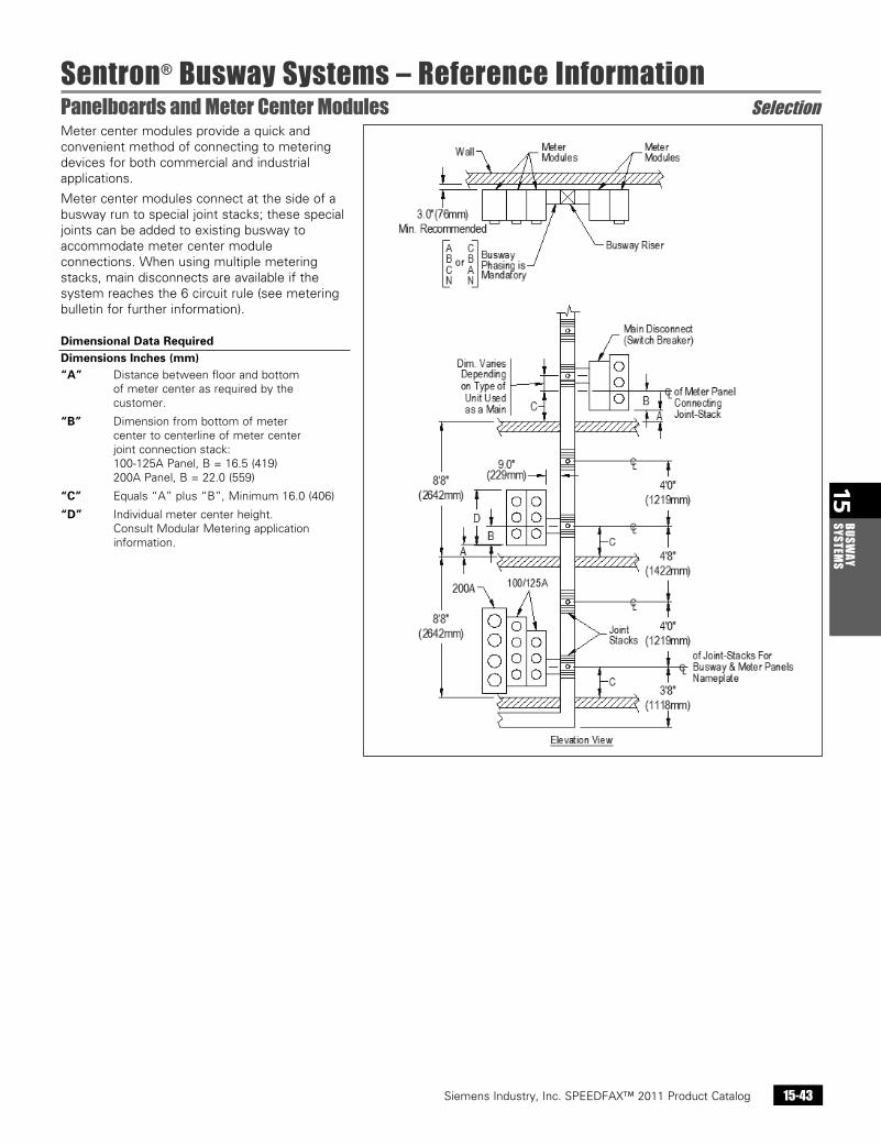
Meter center modules provide a quick and convenient method of connecting to metering devices for both commercial and industrial applications.
Meter center modules connect at the side of a busway run to special joint stacks; these special joints can be added to existing busway to accommodate meter center module connections. When using multiple metering stacks, main disconnects are available if the system reaches the 6 circuit rule (see metering bulletin for further information).
Dimensional Data RequiredDimensions Inches (mm)“A” Distance between floor and bottom
of meter center as required by the customer.
“B” Dimension from bottom of meter center to centerline of meter center joint connection stack: 100-125A Panel, B = 16.5 (419) 200A Panel, B = 22.0 (559)
“C” Equals “A” plus “B”, Minimum 16.0 (406)
“D” Individual meter center height.Consult Modular Metering application information.
Siemens Industry, Inc. SPEEDFAX™ 2011 Product Catalog15-44
15BU
SWAY
SY
STEM
S
Sentron® Busway Systems – Reference Information Selection
Siemens / Speedfax Previous folio: 14-45 NO Edits rev2
Meter Center Module Main Disconnect Meter Module
Side Mount Panelboard
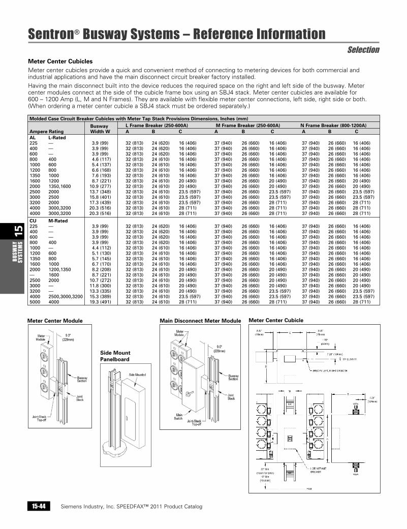
Meter Center CubiclesMeter center cubicles provide a quick and convenient method of connecting to metering devices for both commercial and industrial applications and have the main disconnect circuit breaker factory installed.
Having the main disconnect built into the device reduces the required space on the right and left side of the busway. Meter center modules connect at the side of the cubicle frame box using an SBJ4 stack. Meter center cubicles are available for 600 – 1200 Amp (L, M and N Frames). They are available with flexible meter center connections, left side, right side or both. (When ordering a meter center cubicle a SBJ4 stack must be ordered separately.)
Molded Case Circuit Breaker Cubicles with Meter Tap Stack Provisions Dimensions, Inches (mm) Busway L Frame Breaker (250-600A) M Frame Breaker (250-600A) N Frame Breaker (800-1200A) Ampere Rating Width W A B C A B C A B C AL L-Rated225 — 3.9(99) 32(813) 24(620) 16(406) 37(940) 26(660) 16(406) 37(940) 26(660) 16(406)400 — 3.9(99) 32(813) 24(620) 16(406) 37(940) 26(660) 16(406) 37(940) 26(660) 16(406)600 — 3.9(99) 32(813) 24(620) 16(406) 37(940) 26(660) 16(406) 37(940) 26(660) 16(406)800 400 4.6(117) 32(813) 24(610) 16(406) 37(940) 26(660) 16(406) 37(940) 26(660) 16(406)1000 600 5.4(137) 32(813) 24(610) 16(406) 37(940) 26(660) 16(406) 37(940) 26(660) 16(406)1200 800 6.6(168) 32(813) 24(610) 16(406) 37(940) 26(660) 16(406) 37(940) 26(660) 16(406)1350 1000 7.6(193) 32(813) 24(610) 16(406) 37(940) 26(660) 16(406) 37(940) 26(660) 16(406)1600 1200 8.7(221) 32(813) 24(610) 20(490) 37(940) 26(660) 20(490) 37(940) 26(660) 20(490)2000 1350,1600 10.9(277) 32(813) 24(610) 20(490) 37(940) 26(660) 20(490) 37(940) 26(660) 20(490)2500 2000 13.7(348) 32(813) 24(610) 23.5(597) 37(940) 26(660) 23.5(597) 37(940) 26(660) 23.5(597)3000 2500 15.8(401) 32(813) 24(610) 23.5(597) 37(940) 26(660) 23.5(597) 37(940) 26(660) 23.5(597)3200 2000 17.3(439) 32(813) 24(610) 23.5(597) 37(940) 26(660) 28(711) 37(940) 26(660) 28(711)4000 3000,3200 20.3(516) 32(813) 24(610) 28(711) 37(940) 26(660) 28(711) 37(940) 26(660) 28(711)4000 3000,3200 20.3(516) 32(813) 24(610) 28(711) 37(940) 26(660) 28(711) 37(940) 26(660) 28(711)
CU M-Rated225 — 3.9(99) 32(813) 24(620) 16(406) 37(940) 26(660) 16(406) 37(940) 26(660) 16(406)400 — 3.9(99) 32(813) 24(620) 16(406) 37(940) 26(660) 16(406) 37(940) 26(660) 16(406)600 — 3.9(99) 32(813) 24(620) 16(406) 37(940) 26(660) 16(406) 37(940) 26(660) 16(406)800 400 3.9(99) 32(813) 24(620) 16(406) 37(940) 26(660) 16(406) 37(940) 26(660) 16(406)1000 — 4.4(112) 32(813) 24(610) 16(406) 37(940) 26(660) 16(406) 37(940) 26(660) 16(406)1200 600 5.1(130) 32(813) 24(610) 16(406) 37(940) 26(660) 16(406) 37(940) 26(660) 16(406)1350 800 5.7(145) 32(813) 24(610) 16(406) 37(940) 26(660) 16(406) 37(940) 26(660) 16(406)1600 1000 6.7(170) 32(813) 24(610) 16(406) 37(940) 26(660) 16(406) 37(940) 26(660) 16(406)2000 1200,1350 8.2(208) 32(813) 24(610) 20(490) 37(940) 26(660) 20(490) 37(940) 26(660) 20(490)— 1600 8.7(221) 32(813) 24(610) 20(490) 37(940) 26(660) 20(490) 37(940) 26(660) 20(490)2500 2000 10.7(272) 32(813) 24(610) 20(490) 37(940) 26(660) 20(490) 37(940) 26(660) 20(490)3000 — 11.8(300) 32(813) 24(610) 20(490) 37(940) 26(660) 20(490) 37(940) 26(660) 20(490)3200 — 13.3(335) 32(813) 24(610) 20(490) 37(940) 26(660) 23.5(597) 37(940) 26(660) 23.5(597)4000 2500,3000,3200 15.3(389) 32(813) 24(610) 23.5(597) 37(940) 26(660) 23.5(597) 37(940) 26(660) 23.5(597)5000 4000 19.3(491) 32(813) 24(610) 28(711) 37(940) 26(660) 28(711) 37(940) 26(660) 28(711)
Meter Center Cubicle
Siemens Industry, Inc. SPEEDFAX™ 2011 Product Catalog 15-45
15BUSW
AY SYSTEM
S
Sentron® Busway Systems – Reference InformationInstallation and Application Information Selection
Siemens / Speedfax Previous folio: new page, 14-46 SS 2/13/11
Installation
In preparation for installation of your busway systems, it is important to familiarize yourself with the following installation publications:
b General Instructions For Handling,Installation, Operation and Maintenance of Busway Rated 600 volts or less (NEMA Standards Publication BU1)
b Storage, Installation and Maintainance Instructions for Sentron Busway
These publications should be read through thoroughly and used as reference during installation to ensure proper installation procedures. All
equipment should be inspected upon delivery. If the busway is not installed immediately, it should be stored in a clean, dry location. Factory supplied record drawings as well as installation tools should be accessible in preparation for installation.
UL 1479 Fire Rated Installations
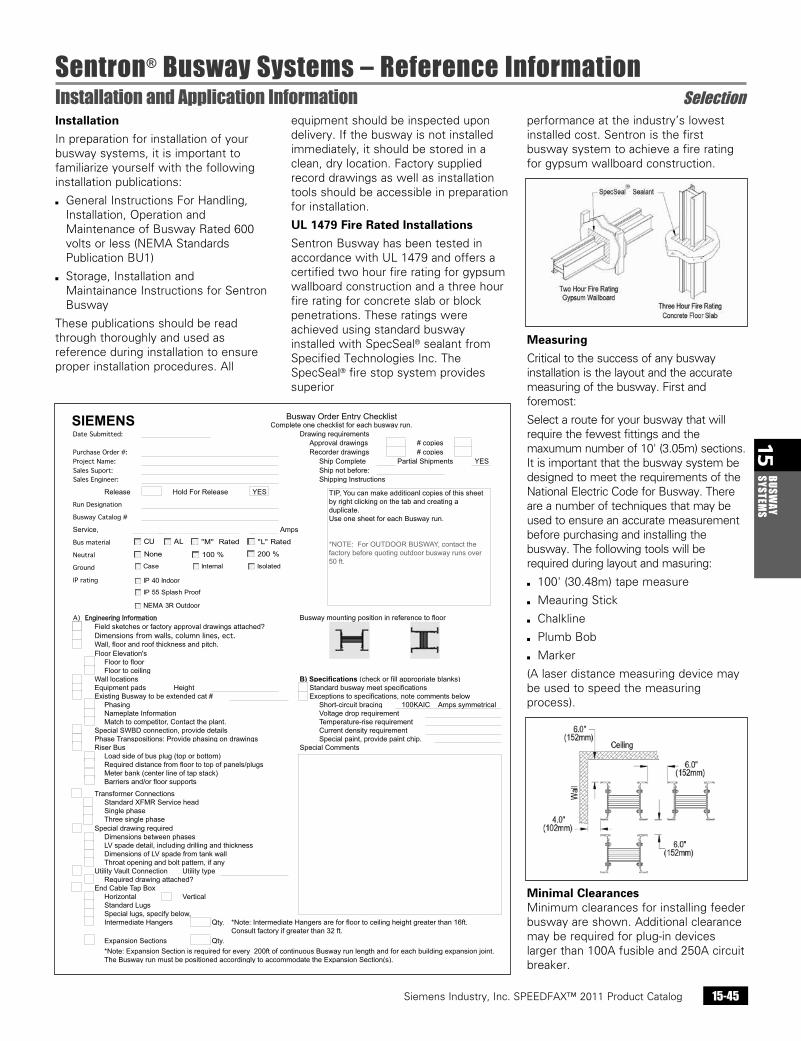
Sentron Busway has been tested in accordance with UL 1479 and offers a certified two hour fire rating for gypsum wallboard construction and a three hour fire rating for concrete slab or block penetrations. These ratings were achieved using standard busway installed with SpecSeal® sealant from Specified Technologies Inc. The SpecSeal® fire stop system provides superior
performance at the industry’s lowest installed cost. Sentron is the first busway system to achieve a fire rating for gypsum wallboard construction.
Measuring
Critical to the success of any busway installation is the layout and the accurate measuring of the busway. First and foremost:
Select a route for your busway that will require the fewest fittings and the maxumum number of 10' (3.05m) sections. It is important that the busway system be designed to meet the requirements of the National Electric Code for Busway. There are a number of techniques that may be used to ensure an accurate measurement before purchasing and installing the busway. The following tools will be required during layout and masuring:
b 100' (30.48m) tape measure
b Meauring Stick
b Chalkline
b Plumb Bob
b Marker
(A laser distance measuring device may be used to speed the measuring process).
Minimal ClearancesMinimum clearances for installing feeder busway are shown. Additional clearance may be required for plug-in devices larger than 100A fusible and 250A circuit breaker.
Siemens Industry, Inc. SPEEDFAX™ 2011 Product Catalog15-46
15BU
SWAY
SY
STEM
S
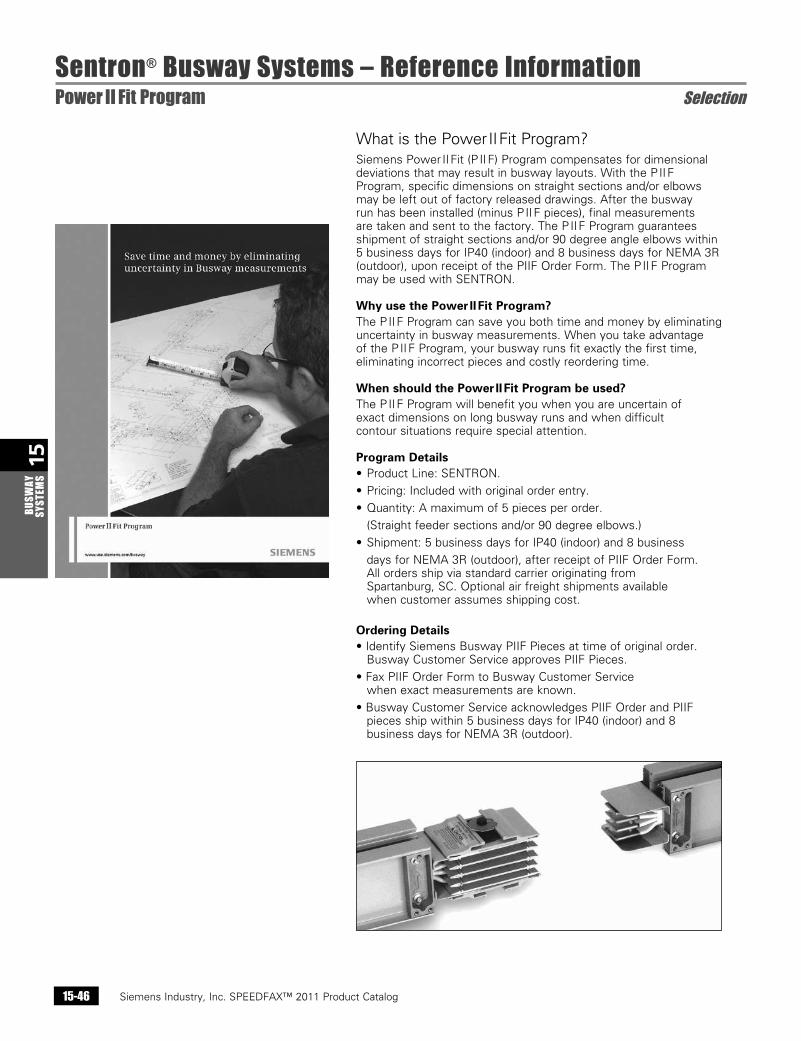
What is the Power II Fit Program?Siemens Power II Fit (P II F) Program compensates for dimensional deviations that may result in busway layouts. With the P II F Program, specific dimensions on straight sections and/or elbows may be left out of factory released drawings. After the busway run has been installed (minus P II F pieces), final measurements are taken and sent to the factory. The P II F Program guarantees shipment of straight sections and/or 90 degree angle elbows within 5 business days for IP40 (indoor) and 8 business days for NEMA 3R (outdoor), upon receipt of the PIIF Order Form. The P II F Program may be used with SENTRON.
Why use the Power II Fit Program?The P II F Program can save you both time and money by eliminating uncertainty in busway measurements. When you take advantage of the P II F Program, your busway runs fit exactly the first time, eliminating incorrect pieces and costly reordering time.
When should the Power II Fit Program be used?The P II F Program will benefit you when you are uncertain ofexact dimensions on long busway runs and when difficultcontour situations require special attention.
Program Details• Product Line: SENTRON.
• Pricing: Included with original order entry.
• Quantity: A maximum of 5 pieces per order.
(Straight feeder sections and/or 90 degree elbows.)
• Shipment: 5 business days for IP40 (indoor) and 8 business
days for NEMA 3R (outdoor), after receipt of PIIF Order Form. All orders ship via standard carrier originating from Spartanburg, SC. Optional air freight shipments available when customer assumes shipping cost.
Ordering Details• Identify Siemens Busway PIIF Pieces at time of original order.
Busway Customer Service approves PIIF Pieces.
• Fax PIIF Order Form to Busway Customer Service when exact measurements are known.
• Busway Customer Service acknowledges PIIF Order and PIIF pieces ship within 5 business days for IP40 (indoor) and 8 business days for NEMA 3R (outdoor).
Sentron® Busway Systems – Reference InformationPower II Fit Program Selection
Siemens Industry, Inc. SPEEDFAX™ 2011 Product Catalog 15-47
15BUSW
AY SYSTEM
S
Sentron® Busway Systems – Reference InformationPower II Measure Selection
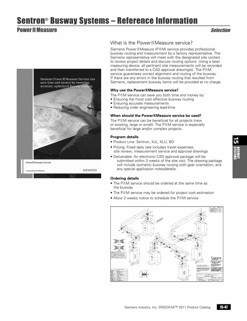
What is the Power II Measure service?Siemens Power II Measure (P II M) service provides professional busway routing and measurement by a factory representative. The Siemens representative will meet with the designated site contact to review project details and discuss routing options. Using a laser measuring device, all pertinent site measurements will be recorded and then transferred to a CAD approval drawing(s). The P II M service guarantees correct alignment and routing of the busway. If there are any errors in the busway routing that resulted from Siemens, replacement busway items will be provided at no charge.
Why use the Power II Measure service?The P II M service can save you both time and money by:• Ensuring the most cost effective busway routing• Ensuring accurate measurements• Reducing order engineering lead-time
When should the Power II Measure service be used?The P II M service can be beneficial for all projects (newor existing, large or small). The P II M service is especiallybeneficial for large and/or complex projects. Program details• Product Line: Sentron, XJL, XLU, BD
• Pricing: Fixed daily rate includes travel expenses, site review, measurement service and approval drawings
• Deliverable: An electronic CAD approval package will be submitted within 3 weeks of the site visit. The drawing package will include isometric busway routing with gear orientation, and any special application notes/details.
Ordering details• The P II M service should be ordered at the same time as
the busway
• The P II M service may be ordered for project cost estimation
• Allow 2 weeks notice to schedule the P II M service
Siemens Industry, Inc. SPEEDFAX™ 2011 Product Catalog15-48
15BU
SWAY
SY
STEM
S
Sentron® Busway Systems – Reference InformationSiemens Sentron Busway Quick Reference General
Siemens / Speedfax Previous folio: 14-47 New Word doc SS 2/13/11
Siemens Sentron Busway Quick ReferenceCritical Dimensions:
Busway that passes through a wall, ceiling or floor: b centerline of a joint to the wall, ceiling or floor = 7 in. min. b centerline of a joint (above a floor support) to a floor = 16 in. min. b joints cannot be positioned inside a wall, ceiling or floor (joints must be accessible for maintenance)
Feeder Busway clearances: b from the top of the busway to a ceiling/floor/wall or other busway = 6 in. min. b from the side of the busway to a ceiling/floor/wall or other busway = 4 in. min
Plug-in Busway clearances: b plug-In busway clearances depend on the configuration of bus plugs (see bus pug clearance charts in the Sentron Selection and Application Guide) b otherwise, clearances for feeder busway apply b note orientation of the operating handle and provide clearance for access & operation
Feeder Busway length: b minimum length = 14.38 in. b maximum length = 10 ft.
Plug-In & Riser length: b available only in 4, 6, 8 and 10 ft. lengths
Flat Elbow section: b maximum leg length = 4 ft. b minimum leg length: Varies according to amperage and bus bar material
Edge Elbow section: b maximum length = 4 ft. b minimum leg length = 10 in.
Combination and Offset Elbows: b maximum leg lengths = 4 ft. b minimum leg lengths: varies according to amperage and bus bar material (See Sentron Selection and Application Guide)
Elbow - Stub Combinations: b maximum leg length = 4 ft. b minimum leg length = 2.50 in. + (case size x .5)
Critical Details:
b busway DRAWINGs must include all releva¬nt dimensions b CENTERLINE dimensions are expected (please note any dimensions that are not center line dimensions) b WALLs and FLOORs must be located (wall & floor thickness must be included) b locate the FRONT of all switchboards and provide the phasing of any existing boards (advise if any PADs are located under boards) b when using RISER plug-in busway please note the desired direction of the load side of bus plugs (G,A,B,C,N from left to right will position the load side to the bottom and “UP is On” handle operation) b TRANSFORMER THROAT connections require complete details. b Horizontal plug-in busway must be oriented with the A phase on top (bolt head on top). b In-Line Disconnect CUBICLEs are engineered to order. The FRONT of the cubicle and Breaker information must be specified. b Panels - panel type and size / if a certain panel or breaker height is required (those dimensions) b Curb height
Intermediate Hangers
b Add qty (1) Intermediate Hanger for floor to ceiling height greater than 16ft. Consult factory if greater than 32 ft.
Expansion Sections:
b Qty (1) Expansion Section should be used for every 200ft of continuous Busway run length and for each building expansion joint. The Busway run must be positioned accordingly to accommodate the Expansion Section(s).
Outdoor Busway:
b route busway to minimize outdoor busway run length b call factory before quoting outdoor busway runs over 50 ft. b avoid installing busway near exhaust pipes that may generate steam or caustic vapors