Embed Size (px)
Citation preview

Sentry Barrier TL-4 ThrieBeam System
Longitudinal MASH TL-4 Barrier Product and Installation Manual Please call Australian Construction Products on 1800 724 172 or visit www.acprod.com.au for more information November 2020 v1.3

Product and Installation Manual: Sentry Barrier TL-4 ThrieBeam System
ACP | November 2020 | Page 2
New South Wales
Sydney 02 8708 4400
Victoria
Melbourne 02 8708 4400
Queensland
Brisbane 07 3442 6200
Western Australia
Perth 02 9772 4172 www.acprod.com.au
Contents Introduction ...................................................................................................................................... 4
System Overview ............................................................................................................................. 4
Limitations and Warnings ................................................................................................................ 5
Training ............................................................................................................................................ 6
Health and Safety............................................................................................................................. 6
Product Traceability ......................................................................................................................... 6
Before Installation ............................................................................................................................ 7
Safety statements ............................................................................................................................ 7
General Safety.............................................................................................................................. 7
Sentry Barrier TL-4 ThrieBeam System Safety Statements ......................................................... 7
Limited Warranty .............................................................................................................................. 8
System Design and Design Considerations .................................................................................... 9
Curbs ............................................................................................................................................ 9
Slopes ........................................................................................................................................... 9
Batter Hinge Proximity .................................................................................................................. 9
Posts on Base Plates ................................................................................................................. 10
Horizontal and Vertical Curves ................................................................................................... 10
Undulating Ground Conditions ................................................................................................... 10
Clear Zone / Hazard Free Zone ................................................................................................. 11
Terminal Ends ............................................................................................................................ 11
Soil Condition ................................................................................................................................ 11
Post Load Testing ...................................................................................................................... 12
Length of Need ............................................................................................................................. 13
System Deflection ......................................................................................................................... 13
Transitions ..................................................................................................................................... 14
Sentry Barrier TL-4 ThrieBeam System - Parts Identification ........................................... 14
Sentry Barrier TL-4 ThrieBeam System – Bill of Materials ............................................................ 15
Sentry Barrier TL-4 ThrieBeam System – Installation ................................................................... 16
Getting Started ........................................................................................................................... 16
Preparation ................................................................................................................................. 16
Soil Conditions............................................................................................................................ 16
Tools Required ............................................................................................................................... 17
Installation Tolerances ................................................................................................................... 18
Sentry Barrier TL-4 ThrieBeam System – Installation Instructions ................................................. 19
Site Preparation .......................................................................................................................... 19

Product and Installation Manual: Sentry Barrier TL-4 ThrieBeam System
ACP | November 2020 | Page 3
New South Wales
Sydney 02 8708 4400
Victoria
Melbourne 02 8708 4400
Queensland
Brisbane 07 3442 6200
Western Australia
Perth 02 9772 4172 www.acprod.com.au
Post Orientation with traffic flow direction .............................................................................. 19
Construction of Terminal End or Crash Cushion ....................................................................... 19
Installation Procedure (Posts and ThrieBeam) .......................................................................... 20
Inspection and Maintenance Frequency ........................................................................................ 23
Maintenance requirement for repair after a Bushfire ..................................................................... 23
Installation Checklist for the Sentry Barrier TL-4 ThrieBeam ........................................................ 24
Frequently Asked Questions .......................................................................................................... 25
Appendices .................................................................................................................................... 26
Appendix A – SENTRY BARRIER TL-4 THRIEBEAM SYSTEM .............................................. 26
Appendix B – SENTRY BARRIER POST TL-4 .......................................................................... 27
Appendix C – INSTALLATION TOLERANCE ............................................................................ 28
Appendix D – SENTRY BARRIER TL-4 THRIEBEAM BARRIER TRANSITION TO SENTRY BARRIER W BEAM ..................................................................................................................... 29
Appendix E – SENTRY BARRIER TL-4 THRIEBEAM BARRIER TRANSITION TO MAX-TENSION TL-2 TERMINAL ......................................................................................................... 30
Appendix F – SENTRY BARRIER TL-4 THRIEBEAM BARRIER TRANSITION TO MAX-TENSION TL-3 TERMINAL ........................................................................................................ 31
Appendix G – SENTRY TL-4 THRIEBEAM BASE PLATE OPTION ......................................... 32

Product and Installation Manual: Sentry Barrier TL-4 ThrieBeam System
ACP | November 2020 | Page 4
New South Wales
Sydney 02 8708 4400
Victoria
Melbourne 02 8708 4400
Queensland
Brisbane 07 3442 6200
Western Australia
Perth 02 9772 4172 www.acprod.com.au
Introduction
The Sentry Barrier TL-4 ThrieBeam System is a roadside Thrie-beam guardrail system suitable for
containing, redirecting and shielding vehicles from roadside obstacles. The barrier has been
designed and tested to meet the evaluation criteria of MASH Test Level 4 for a longitudinal barrier.
This is the current state of the art performance criteria, exceeding the requirements of NCHRP 350
Test Level 4.
The Sentry Barrier TL-4 ThrieBeam System has an initial installation height of 1050 mm to the top
of the rail, providing the system with the ability to withstand numerous road surface overlays without
the need to relevel of lifting of the barrier. The Sentry Barrier TL-4 ThrieBeam System can be
installed with an approved energy absorbing terminal end on the approach end, however it is
recommended that an approved tangential or flared MAX-TENSION terminal end be used for optimal
performance.
The rounded edges to the Sentry Barrier Post TL-4 and closed shape on the approach direction
provide increased protection for vulnerable road users. The compact Sentry Barrier Post TL-4 are
easy to drive into all soil types and provide increased resistance to rotation in the soil when
impacted. Unlike other systems on the market, any damage caused to the top of the posts or to the
rail mounting points during installation will not affect the performance of the system.
The connection system between the rail and posts is formed using conventional fasteners providing
it with the greatest tolerance of any system on the market. If the connection is damaged in any way
it can be easily replaced without replacing the posts allowing for simpler installations and repairs.
The Sentry Barrier TL-4 ThrieBeam System is installed quickly using conventional installation tools
and equipment.
System Overview
The Sentry Barrier TL-4 ThrieBeam System is designed to provide acceptable structural
adequacy, minimal occupant risk and safe vehicle trajectory as required by the latest in safety
standards, AASHTO MASH 16 Test Level 4 (TL4). This standard requires the system to be
independently evaluated with full scaling testing using 1,100 kg and 2,270 kg vehicles traveling at
speeds of 100 km/hr and impacting the system at an angle of 25 degrees, as well as a 10,000 kg
truck travelling at 90 km/hr impacting the system at an angle of 15 degrees. The requirements of
MASH 16 TL4 are so stringent that the system is required to absorb more energy during the impact
than the out-dated NCHRP 350 standard Test Level 4 (TL4).
When impacted by an errant vehicle, the Sentry Barrier TL-4 ThrieBeam System will redirect the
vehicle along the face of the barrier system, bringing it to a controlled stop. The system has been
developed to produce no debris during an impact, with all posts designed to remain firmly located in
the soil and the connection details to remain attached to the rail. Repair of the system is completed
by removing and replacing any bent or damaged ThrieBeam and posts impacted accordingly.

Product and Installation Manual: Sentry Barrier TL-4 ThrieBeam System
ACP | November 2020 | Page 5
New South Wales
Sydney 02 8708 4400
Victoria
Melbourne 02 8708 4400
Queensland
Brisbane 07 3442 6200
Western Australia
Perth 02 9772 4172 www.acprod.com.au
Any posts with damaged connections can be repaired by replacing the connection hardware only,
reducing the need to remove posts and repair damaged ground.
Key specifications for the Sentry Barrier TL-4 ThrieBeam System are:
System Width 200 mm
Height to top of rail 1050 mm
Height to top of post 1040 mm
Post Weight 20.5 kg
Post Length 2000 mm
Post spacing 2.00 m
MASH TL4.10 dynamic deflection (1,100 kg Vehicle) 1.06 m
MASH TL4.11 dynamic deflection (2,270 kg Vehicle) 1.45 m
MASH TL4.12 dynamic deflection (10,000 kg Vehicle) 1.53 m
The minimum Length of Need (LON) of the Sentry Barrier TL-4 ThrieBeam System is dependent on
the posted speed limit. Please refer to state roading authority approval letters for local minimum
length requirements. However, a minimum length of need for a two-way road with a posted speed
limit of 100 km/hr with a clear zone of approaching traffic is recommend as 86 m, excluding terminal
ends.
The Sentry Barrier TL-4 ThrieBeam System systems rails and posts are manufactured from hot-
rolled steel flat products in accordance with AS/NZS 1594 and hot-dip galvanised in accordance with
AS/NZS 4680 with an average minimum coating thickness of 35 microns. All galvanising is
undertaken after fabrication is completed to ensure no surfaces are left untreated.
Limitations and Warnings
The Sentry Barrier TL-4 ThrieBeam System forms part of an approved roadside protection system
and it must be installed in conjunction with an approved terminal end system on both the approach
and trailing ends. When installed in accordance with the manufacturer’s instruction the barrier
system allows an impacting vehicle to be re-directed in a safe and predictable manner under the
MASH impact conditions.
Vehicle impacts that vary from the MASH impact conditions for longitudinal barriers may result in
significantly different outcomes from those obtained in the experimental testing and may not meet
the MASH evaluation criteria.
The selection and placement of the Sentry Barrier TL-4 ThrieBeam System must be in accordance
with the Roading Controlling Authorities guidelines and the details shown in the construction
drawings. Installation must be within strict accordance with the installation instructions for the
product. Alternative installation techniques will be required if the soil conditions on site do not meet
the minimum requirements stated in this manual.

Product and Installation Manual: Sentry Barrier TL-4 ThrieBeam System
ACP | November 2020 | Page 6
New South Wales
Sydney 02 8708 4400
Victoria
Melbourne 02 8708 4400
Queensland
Brisbane 07 3442 6200
Western Australia
Perth 02 9772 4172 www.acprod.com.au
Training
Installers may choose to undergo formal training on the installation of the Sentry Barrier TL-4
ThrieBeam System if they have no prior experience with Sentry Barrier. This includes the correct
identification of each Sentry Barrier TL-4 ThrieBeam System components and installing it as per
the product specification and Installation Manual.
By the end of the training installers will be able to identify each component of the Sentry Barrier TL-
4 ThrieBeam System and have the knowledge to safely install the barrier as per the Installation
Manual and Specifications required.
The training will cover and include the correct Personal Protective Equipment (PPE) required to be
worn during installation and maintenance. Additionally, by the end of the training workers will know
the correct methods required to handle and install all components of the Sentry Barrier TL-4
ThrieBeam System.
Health and Safety
Installers should comply with all necessary health and safety legislation in the local jurisdiction,
including all safe work and lifting practices.
All appropriate traffic safety precautions must be adopted. All workers must wear the required safety
clothing, including but not limited to, high visibility vests, steel capped footwear, gloves and protective
glasses etc.
Before undertaking any earth works, including drilling or driving of posts, always check with the
appropriate service providers that the area is clear of underground services
All installers must be well clear of machinery when posts are being driven.
Product Traceability
The Sentry Barrier TL-4 ThrieBeam system is manufactured
and stamped with traceability batch identification numbers
on core components to ensure traceability of the product
back to the original material certificates.
The photo on the right represents an example of a batch
identification stamp on a Sentry Barrier post, which includes
the manufacturer, grade, thickness and batch stamp details.
Product and Installation Manual: Sentry Barrier TL-4 ThrieBeam System
ACP | November 2020 | Page 7
New South Wales
Sydney 02 8708 4400
Victoria
Melbourne 02 8708 4400
Queensland
Brisbane 07 3442 6200
Western Australia
Perth 02 9772 4172 www.acprod.com.au
Before Installation
Design, selection and placement of the Sentry Barrier TL-4 ThrieBeam System shall be in
accordance with the local Road Controlling Authority’s guidelines and as per the details shown in the
construction drawings. Installation shall be in accordance with the installation instructions supplied
for this product.
The Sentry Barrier TL-4 ThrieBeam System is an engineered safety device. Before starting
installation ensure familiarity with the makeup of the system.
Note: Soil conditions may require a local geotechnical engineer to confirm the soil condition on site met
the required condition described in the manual.
Safety statements
General Safety
➢ All required traffic safety precautions should be complied with. All workers should wear
required safety clothing (examples, but not limited to, include: high visibility vests, steel
capped footwear, gloves etc).
➢ Only authorised trained personnel should operate any machinery. Where overhead
machinery is used, care must be taken to avoid any overhead hazards.
➢ Before drilling or excavation always ensure that the area is clear of underground services.
The appropriate service providers may need to be contacted.
Sentry Barrier TL-4 ThrieBeam System Safety Statements
➢ All installers must be a safe distance from all drilling or excavating machinery operating.
➢ The components are not heavy enough to require specialised lifting equipment (note: check
your local OH&S procedures on lifting weights), but due to the dimensions and bulky nature,
care should be taken when lifting the larger components into position.
➢ Avoid placing hands or fingers in and around moving machine parts when components are
being lifted and manoeuvred into place.

Product and Installation Manual: Sentry Barrier TL-4 ThrieBeam System
ACP | November 2020 | Page 8
New South Wales
Sydney 02 8708 4400
Victoria
Melbourne 02 8708 4400
Queensland
Brisbane 07 3442 6200
Western Australia
Perth 02 9772 4172 www.acprod.com.au
Limited Warranty
Australian Construction Products (ACP) has tested the impact performance of its barriers and crash
cushion systems, and other highway safety hardware under controlled conditions, however, ACP
does not represent nor warrant that the results of those controlled conditions would necessarily avoid
injury to persons or property.
ACP EXPRESSLY DISCLAIMS ANY WARRANTY OR LIABILITY FOR CLAIMS ARISING BY REASONS OF DEATH OR PERSONAL INJURY OR DAMAGE TO PROPERTY RESULTING FROM ANY IMPACT, COLLISION OR HARMFUL CONTACT WITH THE PRODUCTS OR NEARBY HAZARDS OR OBJECTS BY ANY VEHICLE, OBJECTS OR PERSONS.
ACP warrants that any product or component part manufactured by ACP will be free from defects in
material or workmanship. ACP will replace free of cost any Product or component part manufactured
by ACP that contains such a defect.
THE FOREGOING WARRANTY IS IN LIEU OF AND EXCLUDES ALL OTHER WARRANTIES NOT EXPRESSLY SET FORTH HEREIN, WHETHER EXPRESS OR IMPLIED BY OPERATION OF LAW OR OTHERWISE, INCLUDING BUT NOT LIMITED TO ANY IMPLIED WARRANTIES OF MERCHANTABILITY OR FITNESS FOR A PARTICULAR PURPOSE. ACP’S LIABILITY UNDER THIS WARRANTY IS EXPRESSLY LIMITED TO REPLACEMENT FREE OF COST OF PARTS SUPPLIED BY ACP ONLY (IN THE FORM AND UNDER THE TERMS ORIGINALLY SHIPPED), OR TO REPAIR OR TO MANUFACTURE BY ACP, PRODUCTS OR PARTS NOT COMPLYING WITH ACP SPECIFICATIONS, OR, AT ACP’S ELECTION, TO THE REPAYMENT OF AN AMOUNT EQUAL TO THE PURCHASE PRICE OF SUCH PRODUCTS OR PARTS, WHETHER SUCH CLAIMS ARE FOR BREACH OF WARRANTY OR NEGLIGENCE. ACP SHALL NOT BE LIABLE FOR ANY INCIDENTAL, CONSEQUENTIAL OR SPECIAL LOSSES, DAMAGES OR EXPENSES OF ANY KIND, INCLUDING, WITHOUT LIMITATION, ANY SUCH LOSSES, DAMAGES OR EXPENSES ARISING DIRECTLY OR INDIRECTLY FROM THE SALE, HANDLING OR USE OF THE PRODUCTS FROM ANY OTHER CAUSE RELATING THERETO, OR FROM PERSONAL INJURY OR LOSS OF PROFIT.
Any claim by the Buyer with reference to Products sold hereunder for any cause shall be deemed
waived by the Buyer unless ACP is notified in writing, in the case of defects apparent on visual
inspection, within ninety (90) days from the delivery date, or, in the case of defects not apparent on
visual inspection, within twelve (12) months from the said delivery date. Products claimed to be
defective may be returned prepaid to ACP’s plant for inspection in accordance with return shipping
instructions that ACP shall furnish to the Buyer forthwith upon receipt of the Buyer’s notice of claim. If
the claim is established, ACP will reimburse that Buyer for all carriage costs incurred hereunder.
The forgoing warranty benefits shall not apply to (i) any Products that have been subject to improper
storage, accident, misuse or unauthorised alterations, or that have not been installed, operated and
maintained in accordance with approved procedures and (ii) any components manufactured by the
Buyer.

Product and Installation Manual: Sentry Barrier TL-4 ThrieBeam System
ACP | November 2020 | Page 9
New South Wales
Sydney 02 8708 4400
Victoria
Melbourne 02 8708 4400
Queensland
Brisbane 07 3442 6200
Western Australia
Perth 02 9772 4172 www.acprod.com.au
System Design and Design Considerations
Curbs As with all roadside safety hardware, the Sentry Barrier TL-4 ThrieBeam System has been
designed and tested so that the centre of gravity of the impacting vehicle is at a constant height in
relation to the system. For this reason, it is preferred that curbs or channels are not in front or directly
behind the Sentry Barrier TL-4 ThrieBeam System as they may result in altering the height of the
vehicle at impact.
If interaction with a curb cannot be avoided consult the local Road Controlling Authority guidelines
regarding allowable curb heights, curb shapes, and barrier offset distance.
Slopes The Sentry Barrier TL-4 ThrieBeam System can be installed on ground with a maximum cross fall
of 6H:1V. For steeper slopes it is recommended that the system is installed no closer than 400 mm
to the batter hinge point of the slope, please refer to below for guidance. If installations with less
clearance are required, please contact your local ACP Distributor.
Batter Hinge Proximity The offset proximity of the Sentry Barrier TL-4 ThrieBeam System to the batter hinge point of a
slope is dependent upon the design containment level of the road. For a TL-3 containment level, the
minimum proximity to the hinge point shall be minimum 400 mm from the back edge of the post to
the Batter Hinge Point as shown in the figure below. For a TL-4 containment level, the minimum
proximity to the hinge point measured from the face of the rail, shall be equal to the expected
deflection at TL-4, which is 1530 mm. Refer to below figure for guidance.
Installations in proximity to a batter hinge point should also be considered within the requirements of
the road controlling authority Extended Design Domain requirements, where applicable.

Product and Installation Manual: Sentry Barrier TL-4 ThrieBeam System
ACP | November 2020 | Page 10
New South Wales
Sydney 02 8708 4400
Victoria
Melbourne 02 8708 4400
Queensland
Brisbane 07 3442 6200
Western Australia
Perth 02 9772 4172 www.acprod.com.au
Posts on Base Plates In the event the Sentry Barrier TL-4 ThrieBeam System cannot be installed to the required in-
ground depth, the use of a base plate mounted on a suitable foundation can be adopted. Posts on
base plates are typically used at culvert locations, and in areas where underground services restrict
posts from being driven into the ground. Refer to Appendix G – SENTRY TL-4 THRIEBEAM BASE
PLATE OPTION. Contact ACP for concrete footing detail and for any further guidance and
information if required.
Horizontal and Vertical Curves The Sentry Barrier TL-4 ThrieBeam System can accommodate both horizontally and vertically
curved guardrail panels if required by site conditions. For radii less than 25m the system must be
anchored with an approved intermediate anchor or terminal end. Please refer to approved details of
the local Road Controlling Authority where necessary.
Concave Corner Convex Corner
Undulating Ground Conditions Site specific grading may be necessary to ensure that there are no ‘humps’ or ‘hollows’ that may
significantly alter the impacting vehicles stability or substantially alter the ThrieBeam heights in
relation to the ground. The Sentry Barrier TL-4 ThrieBeam System is required to be installed level

Product and Installation Manual: Sentry Barrier TL-4 ThrieBeam System
ACP | November 2020 | Page 11
New South Wales
Sydney 02 8708 4400
Victoria
Melbourne 02 8708 4400
Queensland
Brisbane 07 3442 6200
Western Australia
Perth 02 9772 4172 www.acprod.com.au
and centred on the barrier line as stated in the Installation Procedure.
Care must be taken to ensure all posts in the Sentry Barrier TL-4 ThrieBeam System are installed
to the correct height, alignment and orientation. It is strongly recommended that smoothing of
uneven ground conditions be completed along the length of the Sentry Barrier TL-4 ThrieBeam
System.
Clear Zone / Hazard Free Zone Clear Zones are areas adjacent to traffic lanes that provide errant vehicles the opportunity to slow
down or recover. The clear zone must be kept clear from roadside features that could be hazardous
to errant vehicles, such as but not limited to trees, poles and culverts. Although it is desirable to
maximize the available clear zone, please refer to your local Road Controlling Authority for
confirmation of the minimum width requirements.
Terminal Ends The Sentry Barrier TL-4 ThrieBeam System is designed to be compatible with a range of guardrail
terminals ends or crash cushions available, in accordance with designated transition details. It is
recommended that MAX-TENSION terminal ends be used with the Sentry Barrier TL-4 ThrieBeam
System for optimal performance. The X-TENSION 350 terminal ends can also be utilised if required.
Refer to the Appendices section for detailed drawings.
The purpose of the guardrail terminals ends, or crash cushions is to provide a soft impact and to
prevent the end rail from spearing or impacting the errant vehicle. The terminal ends and crash
cushions also provide tensile and deflection strength necessary to ensure the errant vehicle is
redirected for the length-of-need required.
➢ Care must be taken to ensure the correct post spacing is ALWAYS used during the
installation.
➢ Care must be taken to ensure the posts are orientated correctly during installation and to
ensure all ThrieBeam bolts are inserted and tightened accordingly.
➢ Care must be taken to ensure the line posts are installed at the correct height.
Soil Condition
The Sentry Barrier TL-4 ThrieBeam System is a soil-mounted system driven directly into the soil.
To meet the barrier’s performance, the soil is required to meet AASHTO Standard Soil (Grade B)
and requirements set out by AS/NZS 3845 and (if applicable) TNZ Specification M/4 2006.
Additionally, you should refer to the local Roading Controlling Authorities guidelines for minimum soil
requirements for road safety barrier installation.
Soil conditions on site that do not meet these requirements will require alternative installation or
further investigation. Contact your ACP distributor for guidance.
It is strongly recommended that soil tests be completed at the location where the Sentry Barrier TL-
4 ThrieBeam System is to be installed.

Product and Installation Manual: Sentry Barrier TL-4 ThrieBeam System
ACP | November 2020 | Page 12
New South Wales
Sydney 02 8708 4400
Victoria
Melbourne 02 8708 4400
Queensland
Brisbane 07 3442 6200
Western Australia
Perth 02 9772 4172 www.acprod.com.au
Post Load Testing
To ensure soil conditions on site meet the
required resistance in the ground for the
system to perform adequately. A Sentry
Barrier TL-4 post should be installed at
the required site location and pull tested.
The method involves applying a 5KN
(510kg.f) force at 700mm above ground
level using a soft strop or similar, capable
of sustaining such force. The maximum
permanent post deflection allowable
onsite is 5mm (+5mm) horizontally at the
ground level. Therefore, the tolerance
allowable is 0-10mm.
Note: All technical information required to
assist in designing a site-specific
foundation is available from ACP
Distributor.
IF SOIL CONDITIONS ON SITE DO NOT MEET OR EXCEED THE REQUIRED STRENGTH, SITE SPECIFIC CONDITIONS, REFER TO A LOCAL GEOTECHNICAL ENGINEER FOR FURTHER ADVICE.

Product and Installation Manual: Sentry Barrier TL-4 ThrieBeam System
ACP | November 2020 | Page 13
New South Wales
Sydney 02 8708 4400
Victoria
Melbourne 02 8708 4400
Queensland
Brisbane 07 3442 6200
Western Australia
Perth 02 9772 4172 www.acprod.com.au
Length of Need
The minimum Length of Need (LoN) of the Sentry Barrier TL-4 ThrieBeam System is dependent on
the specific hazard being protected and the posted speed limit. The default Length of Need (LoN)
determined through crash testing is 86.0m excluding transitions and terminal ends, however, refer to
state roading authority approval letters for local minimum length requirements where applicable.
Designers should also refer to the Austroads Guide to Road Design – Part 6, Section 6.3, for
detailed design process of barrier length run required.
For sites where geometric constraints exist, designers may require shorter length of need, in such
instances, a 12m* length of need for TL-3 containment design can be utilised plus the length of the
transition and terminal end regions on either end of the barrier system. For TL-4 containment design,
a 20m* length of need can be utilised plus transition and terminal end regions. We recommend
designers or Installers contact their local Roading Control Authority for further information or
guidance if required.
* These lengths have been calculated based upon the actual vehicle contact lengths from the
respective Test 4-11 and Test 4-12 crash test articles noted in the crash test report.
System Deflection
The transverse deflection of a barrier during a crash is dependent upon the mass, speed, and impact
angle of the errant vehicle. The maximum levels of dynamic deflections measured during impact
testing are presented below.
Test 4-10 Test 4-11 Test 4-12
Vehicle Type Car Pick up Truck
Vehicle Mass 1,100 kg 2,270 kg 10,000 kg
Vehicle Speed 100 km/hr 100 km/hr 90 km/hr
Impact Angle 25° 25° 15°
Dynamic Deflection 1.06 m 1.45 m 1.53 m
Crash testing typically represents the extremes impact parameters. A review of the proposed barrier
location can be undertaken to assess the following variables influence on the likely maximum system
deflection;
• Maximum attainable impact angle;
• Design speed; and
• Design vehicle.
Note:
The TL-3 containment level is measured in Test 4-11 i.e. Dynamic Deflection of 1.45m.
The TL-4 containment level is measured in Test 4-12 i.e. Dynamic Deflection of 1.53m

Product and Installation Manual: Sentry Barrier TL-4 ThrieBeam System
ACP | November 2020 | Page 14
New South Wales
Sydney 02 8708 4400
Victoria
Melbourne 02 8708 4400
Queensland
Brisbane 07 3442 6200
Western Australia
Perth 02 9772 4172 www.acprod.com.au
Transitions
A transition zone may be required to connect the Sentry Barrier TL-4 ThrieBeam System to other
types of barriers or non-approved terminal ends. Refer to the Appendices section for guidance.
Please contact your ACP distributor for guidance on acceptable transitions systems if required.
The Sentry Barrier TL-4 ThrieBeam System can be connected to approved proprietary or public
domain terminal ends through a transition zone. Refer to the Appendices section for designated
transition drawings.
Sentry Barrier TL-4 ThrieBeam System - Parts
Identification
Sentry Barrier TL-4 ThrieBeam System Post (2 views)
Sentry Barrier Bolt, Washer and Nut ThrieBeam Splice Bolt and Nut

Product and Installation Manual: Sentry Barrier TL-4 ThrieBeam System
ACP | November 2020 | Page 15
New South Wales
Sydney 02 8708 4400
Victoria
Melbourne 02 8708 4400
Queensland
Brisbane 07 3442 6200
Western Australia
Perth 02 9772 4172 www.acprod.com.au
ALL STEEL COMPONENTS USED IN THE SENTRY BARRIER TL-4 THRIEBEAM SYSTEM ARE HOT DIPPED GALVANISED IN ACCORDANCE WITH AS/NZS 4680 (AVERAGE MINIMUM COASTING THICKNESS SHOULD BE 35 MICRONS) WITH THE EXCEPTION OF THE ACP SENTRY BARRIER WASHER BEING SPUN GALVANISED.
Sentry Barrier TL-4 ThrieBeam System – Bill of Materials
Bill of Materials – Checklist per panel (4 m of barrier) installed
Yes
➢ 2x Sentry Barrier TL-4 ThrieBeam System Posts (per ThrieBeam)
➢ 2x ACP Sentry Barrier Bolt, Washer and Nut (one per post connection)
➢ 1x 4m ThrieBeam Rail
➢ 12x Splice Bolts and Nuts (at the end of ThrieBeam and overlapping the
prior ThrieBeam)
General equipment required ➢ Drilling or compactor suitable for foundation
➢ String line and pegs
➢ Measuring tape
➢ Level
➢ 32mm Wrench
➢ 32mm Ring Spanner
➢ Suitable driving head with machined Sentry post profile

Product and Installation Manual: Sentry Barrier TL-4 ThrieBeam System
ACP | November 2020 | Page 16
New South Wales
Sydney 02 8708 4400
Victoria
Melbourne 02 8708 4400
Queensland
Brisbane 07 3442 6200
Western Australia
Perth 02 9772 4172 www.acprod.com.au
Sentry Barrier TL-4 ThrieBeam System – Installation
Getting Started The Sentry Barrier TL-4 ThrieBeam System is a ThrieBeam barrier designed to run the length of
need required and is attached to a compatible terminal end or crash cushion through a designated
transition, refer to the Appendices section. For guidance on minimum Length of Need (LON), refer to
the Length of Need section earlier in the manual.
Preparation Before installing an Sentry Barrier TL-4 ThrieBeam System, ensure that all components required
for the system are on site and have been identified. The Sentry Barrier TL-4 ThrieBeam System is
an engineered safety device. Before starting installation ensure familiarity with the makeup of the
system. Refer to the Bill of Materials and Parts Identification sections in this manual for more
information.
Ensure that the area where the Sentry Barrier TL-4 ThrieBeam System is to be installed is
sufficiently flat so that the posts and ThrieBeam can be installed within the allowable tolerance and
aligned to the terminal ends or crash cushions. Minor site grading may be required.
Soil Conditions The Sentry Barrier TL-4 ThrieBeam System has been designed to withstand a constant static
load, thermal loading, and dynamic impact load that can be applied from the impact of an errant
vehicle. To perform, the Sentry Barrier TL-4 ThrieBeam System must be attached to either a semi
rigid or rigid terminal end or crash cushion after a designated transition region to provide the
necessary safety benefits. It is recommended that the soil tests are carried out at the location the
Sentry Barrier TL-4 ThrieBeam System prior to being installed.
IF SOIL CONDITIONS ON SITE DO NOT MEET OR EXCEED THE REQUIRED STRENGTH DETAILED IN THIS MANUAL, SITE SPECIFIC FOUNDATIONS MUST BE DESIGNED BY A LOCAL GEOTECHNICAL ENGINEER

Product and Installation Manual: Sentry Barrier TL-4 ThrieBeam System
ACP | November 2020 | Page 17
New South Wales
Sydney 02 8708 4400
Victoria
Melbourne 02 8708 4400
Queensland
Brisbane 07 3442 6200
Western Australia
Perth 02 9772 4172 www.acprod.com.au
Tools Required
The tools required to install the Sentry Barrier TL-4 ThrieBeam System are similar to other
ThrieBeam barriers. It requires:
➢ Appropriate personal protective equipment
➢ Drilling or compactor machinery (suitable for soil conditions
and with a driving head to avoid damage to posts during
installation)
➢ String line
➢ Measuring tape
➢ Level

Product and Installation Manual: Sentry Barrier TL-4 ThrieBeam System
ACP | November 2020 | Page 18
New South Wales
Sydney 02 8708 4400
Victoria
Melbourne 02 8708 4400
Queensland
Brisbane 07 3442 6200
Western Australia
Perth 02 9772 4172 www.acprod.com.au
➢ 32mm Socket wrench or Ratchet
➢ 32mm Ring spanner
Installation Tolerances
The Sentry Barrier TL-4 ThrieBeam System is an engineered safety device. To obtain optimal
performance is it important to install all components of the system to within the allowable tolerances
stated below (also in Appendix C). Particular care must be taken to ensure;
• Suitable horizontal alignment and verticality of the line posts.
• Consistency in the vertical height of the line posts.
• Orientation and height of the terminal end or crash cushion.
Sentry Barrier TL-4 ThrieBeam System has to be installed at 1040mm to the top of the post. A
vertical height tolerance of ±25mm is acceptable for both the Sentry Barrier Post TL-4. The top of
the ThrieBeam is to be positioned 10mm above the top of the Sentry Barrier Post TL-4 with a
tolerance of ±5mm. The Sentry Barrier Post TL-4 laterally is constrained to ±15mm tolerance. It is
of upmost importance for these tolerances to be adhered to in order to ensure safe function of the
Sentry Barrier TL-4 ThrieBeam System.

Product and Installation Manual: Sentry Barrier TL-4 ThrieBeam System
ACP | November 2020 | Page 19
New South Wales
Sydney 02 8708 4400
Victoria
Melbourne 02 8708 4400
Queensland
Brisbane 07 3442 6200
Western Australia
Perth 02 9772 4172 www.acprod.com.au
Sentry Barrier TL-4 ThrieBeam System – Installation
Instructions
Before installing the Sentry Barrier TL-4 ThrieBeam System, ensure that all components required
for the system are on site and have been identified. The Sentry Barrier TL-4 ThrieBeam System is
an engineered safety device made up of relatively small number of parts. Please ensure familiarity
with the makeup of the system and the installation process prior to commencing. If required, refer to
the Bill of Materials and Parts Identification sections in this manual for more information.
Site Preparation It is preferred that the Sentry Barrier TL-4 ThrieBeam System be installed on flat, level ground and
tethered to an approved terminal end or crash cushion. The positioning of the Sentry Barrier TL-4
ThrieBeam System commences from the last post connected to the asymmetric transition rail (on
ThrieBeam end), working upstream to the prior asymmetric transition rail. It is recommended that a
string line be used to obtain the correct orientation and placement of the posts.
Post Orientation with traffic flow direction Ensure posts are correctly orientated in relation to traffic flow direction by positioning the closed side of the post towards oncoming traffic. Refer to below.
BEFORE DRILLING OR EXCAVATION ALWAYS ENSURE THAT THE AREA IS CLEAR OF UNDERGROUND SERVICES
Construction of Terminal End or Crash Cushion The Sentry Barrier TL-4 ThrieBeam System is compatible with a variety of terminal ends and
crash cushions depending upon the availability of designated transition details and Local Road
Controlling Authority approval specifications. Refer to the Appendices section and Local Road
Controlling Authority approval specifications for details. The selection of a suitable design will depend
primarily upon the soil type, and geometric constraints of the site. Please refer to the relevant
terminal end or crash cushion Installation Manual for guidance to the construction and installation
procedure of that specific device.

Product and Installation Manual: Sentry Barrier TL-4 ThrieBeam System
ACP | November 2020 | Page 20
New South Wales
Sydney 02 8708 4400
Victoria
Melbourne 02 8708 4400
Queensland
Brisbane 07 3442 6200
Western Australia
Perth 02 9772 4172 www.acprod.com.au
Installation Procedure (Posts and ThrieBeam)
Step 1
Review the site location and identify possible hazards
prior to commencing the installation of the Sentry
Barrier TL-4 ThrieBeam System. Any concerns,
please refer to the local Roading Authority.
Step 2
Place a string line from the centre of the downstream asymmetric rail to required location of the
upstream asymmetric rail. The string line should pass over the centre of each post location and be
marked accordingly as the required location for drilling or driving each post.

Product and Installation Manual: Sentry Barrier TL-4 ThrieBeam System
ACP | November 2020 | Page 21
New South Wales
Sydney 02 8708 4400
Victoria
Melbourne 02 8708 4400
Queensland
Brisbane 07 3442 6200
Western Australia
Perth 02 9772 4172 www.acprod.com.au
Step 3
Identify the correct orientation of the post (refer to Appendix A - SENTRY BARRIER TL-4
THRIEBEAM SYS) and drive post to the predetermined depth of 960mm (1040 mm protruding
above ground) as stipulated in Appendix A. The post must be vertically aligned and within the
tolerance level stated in the Installation Tolerances section. The driving of the post should not incur
any damage to the post. If a post is damaged it must be inspected and removed if considered that
the damage will affect the performance.
Step 4
Supporting the ThrieBeam in the desire location, install the Sentry Barrier Bolt, Washer and Nut in
the top post slot only. Once supported, the 12 Splice Bolts and Nuts can be inserted into the
ThrieBeam splice joint. It is vital that each ThrieBeam must overlap the prior ThrieBeam positioned
downstream. Failure to correctly overlap the ThrieBeam may cause snagging, poor barrier
performance or risk injury or death to the driver of the errant vehicle. Snug tighten all bolts once
installed.
Splice Joint location

Product and Installation Manual: Sentry Barrier TL-4 ThrieBeam System
ACP | November 2020 | Page 22
New South Wales
Sydney 02 8708 4400
Victoria
Melbourne 02 8708 4400
Queensland
Brisbane 07 3442 6200
Western Australia
Perth 02 9772 4172 www.acprod.com.au
ThrieBeam Ends
Intermediary Post (middle section)

Product and Installation Manual: Sentry Barrier TL-4 ThrieBeam System
ACP | November 2020 | Page 23
New South Wales
Sydney 02 8708 4400
Victoria
Melbourne 02 8708 4400
Queensland
Brisbane 07 3442 6200
Western Australia
Perth 02 9772 4172 www.acprod.com.au
Step 5
Continue working along the barrier from the first installed ThrieBeam to the terminal end or crash
cushion positioned at the other end of the barrier system. Once the barrier is installed a detailed
visual inspection should be completed to install all components are correctly installed. All bolts
should be confirmed to be installed snug tight.
Inspection and Maintenance Frequency
The Sentry Barrier TL-4 ThrieBeam System is maintenance free. However, it is recommended that
all ThrieBeam barrier systems are checked after being impacted to ensure that the appropriate
strength is maintained. Refer to Installation Procedure in this manual for more information.
Maintenance requirement for repair after a Bushfire
Following a severe bushfire, a detailed inspection of the Sentry Barrier TL-4 ThrieBeam System
should be undertaken. If heat damage is noted, it is recommended the ThrieBeam and posts are
replaced immediately.
A detailed inspection should also be completed on the post footings and the transition between the
ThrieBeam barrier and terminal end or crash cushion. Any concerns, please refer to the Sentry
Barrier TL-4 ThrieBeam System Product Manual or contact ACP for recommendations or
inspections of the Sentry Barrier TL-4 ThrieBeam System itself.

Product and Installation Manual: Sentry Barrier TL-4 ThrieBeam System
ACP | November 2020 | Page 24
New South Wales
Sydney 02 8708 4400
Victoria
Melbourne 02 8708 4400
Queensland
Brisbane 07 3442 6200
Western Australia
Perth 02 9772 4172 www.acprod.com.au
Installation Checklist for the Sentry Barrier TL-4 ThrieBeam
Comments:
Contact ACP for more information on this or other road safety products.
Y
N
General
➢ Ensure the posts are orientated in the correct direction and consistent with the terminal ends or crash cushions.
➢ The height of the finished rail should be 1050 mm (±25 mm) above the finished ground level.
➢ The height to the top of the posts should be 1040 mm (±25 mm) above finished ground level.
➢ The posts are free from damage.
➢ The correct ACP Sentry Barrier Washer is installed and seated correctly in the back of the post.
➢ All bolts are installed and tightened snug. Ensure only one post bolt is installed in the top slot per post.
➢ The ThrieBeam must be level and aligned in accordance with the general assembly drawing and transition drawings where applicable. Refer to Appendix A for guidance.
➢ Ensure posts are free of debris prior to installing the ThrieBeam.
Connected to a Terminal End or Crash Cushion
➢ The Sentry Barrier TL-4 ThrieBeam System must transition to the nominated terminal end in accordance with transition drawings. Refer to Appendices for details.
Location:
Installed by: Date:
Inspected by: Date:

Product and Installation Manual: Sentry Barrier TL-4 ThrieBeam System
ACP | November 2020 | Page 25
New South Wales
Sydney 02 8708 4400
Victoria
Melbourne 02 8708 4400
Queensland
Brisbane 07 3442 6200
Western Australia
Perth 02 9772 4172 www.acprod.com.au
Frequently Asked Questions
1. What type of equipment is required to install the Sentry Barrier TL-4 ThrieBeam System?
Standard tools required include a wrench, measuring tape, string line and machinery suitable for
drilling or compacting the post into soil.
2. Does your company provide spare parts? What is the lead-time for supply?
It is important to fix a damaged ThrieBeam barrier as soon possible because it most probably won’t
perform as designed when damaged. For this reason it is recommended that spares are held by
Maintenance Contractors. The lead time for parts will generally be next day delivery or collection
from one of our distribution centres.
3. On average, how long does it take to install the Sentry Barrier TL-4 ThrieBeam System?
Depending on circumstances at the site, installation and assembly of the system should take a three
person crew less than 15 mins per ThrieBeam panel (4.0 m length) when using automatic post
driving equipment. Installation time will vary depending on ground conditions when hand digging
and re-compacting posts.
4. What about vandalism, can the Sentry Barrier TL-4 ThrieBeam System be damaged easily?
No, once the system has been fully installed it becomes a rigid system unlikely to be damaged or
weaken the performance of the system.
5. How easily can the Sentry Barrier TL-4 ThrieBeam System be restored after impact?
Sentry Barrier TL-4 ThrieBeam System is easily repaired following an impact. Damaged posts can
be removed using a crowbar (or other appropriate equipment) and new posts installed before
replacement ThrieBeams and splice bolts are positioned.
The connection detail used between the post and the rail of the Sentry Barrier TL-4 ThrieBeam
System is designed to limit damage to the post outside of the immediate zone of impact. When the
connection is damaged, the washer detail can be easily replaced without needing to replace the post
(provided post is not damaged from an impact).
6. What maintenance does the Sentry Barrier TL-4 ThrieBeam System require?
The Sentry Barrier TL-4 ThrieBeam System is maintenance free. However, it is recommended that
all ThrieBeam barrier systems are checked after impacts to ensure that the integrity of the barrier is
maintained.
Product and Installation Manual: Sentry Barrier TL-4 ThrieBeam System
ACP | November 2020 | Page 26
New South Wales
Sydney 02 8708 4400
Victoria
Melbourne 02 8708 4400
Queensland
Brisbane 07 3442 6200
Western Australia
Perth 02 9772 4172 www.acprod.com.au
Appendices
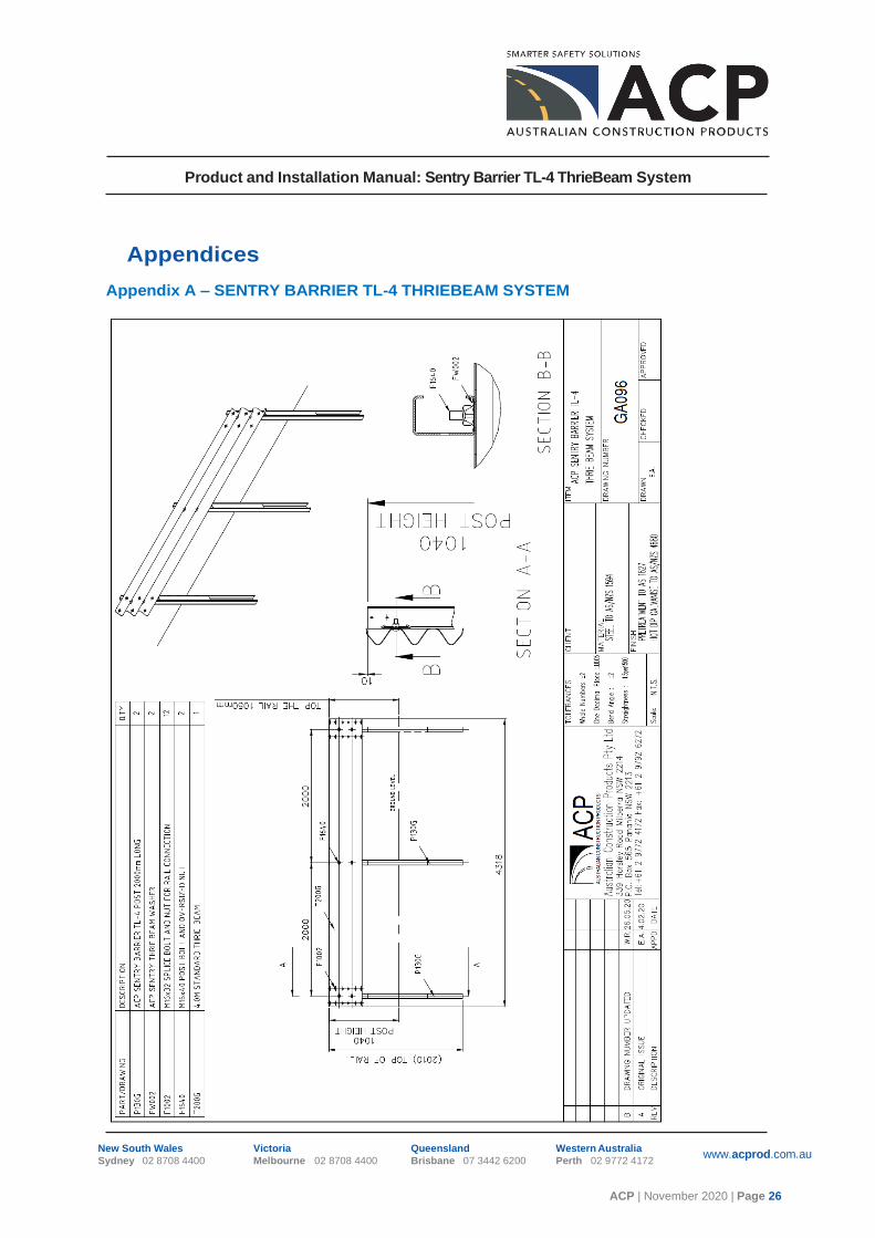
Appendix A – SENTRY BARRIER TL-4 THRIEBEAM SYSTEM

Product and Installation Manual: Sentry Barrier TL-4 ThrieBeam System
ACP | November 2020 | Page 27
New South Wales
Sydney 02 8708 4400
Victoria
Melbourne 02 8708 4400
Queensland
Brisbane 07 3442 6200
Western Australia
Perth 02 9772 4172 www.acprod.com.au
Appendix B – SENTRY BARRIER POST TL-4

Product and Installation Manual: Sentry Barrier TL-4 ThrieBeam System
ACP | November 2020 | Page 28
New South Wales
Sydney 02 8708 4400
Victoria
Melbourne 02 8708 4400
Queensland
Brisbane 07 3442 6200
Western Australia
Perth 02 9772 4172 www.acprod.com.au
Appendix C – INSTALLATION TOLERANCE

Product and Installation Manual: Sentry Barrier TL-4 ThrieBeam System
ACP | November 2020 | Page 29
New South Wales
Sydney 02 8708 4400
Victoria
Melbourne 02 8708 4400
Queensland
Brisbane 07 3442 6200
Western Australia
Perth 02 9772 4172 www.acprod.com.au
Appendix D – SENTRY BARRIER TL-4 THRIEBEAM BARRIER TRANSITION TO SENTRY
BARRIER W BEAM

Product and Installation Manual: Sentry Barrier TL-4 ThrieBeam System
ACP | November 2020 | Page 30
New South Wales
Sydney 02 8708 4400
Victoria
Melbourne 02 8708 4400
Queensland
Brisbane 07 3442 6200
Western Australia
Perth 02 9772 4172 www.acprod.com.au
Appendix E – SENTRY BARRIER TL-4 THRIEBEAM BARRIER TRANSITION TO MAX-
TENSION TL-2 TERMINAL

Product and Installation Manual: Sentry Barrier TL-4 ThrieBeam System
ACP | November 2020 | Page 31
New South Wales
Sydney 02 8708 4400
Victoria
Melbourne 02 8708 4400
Queensland
Brisbane 07 3442 6200
Western Australia
Perth 02 9772 4172 www.acprod.com.au
Appendix F – SENTRY BARRIER TL-4 THRIEBEAM BARRIER TRANSITION TO MAX-TENSION TL-3 TERMINAL

Product and Installation Manual: Sentry Barrier TL-4 ThrieBeam System
ACP | November 2020 | Page 32
New South Wales
Sydney 02 8708 4400
Victoria
Melbourne 02 8708 4400
Queensland
Brisbane 07 3442 6200
Western Australia
Perth 02 9772 4172 www.acprod.com.au
Appendix G – SENTRY TL-4 THRIEBEAM BASE PLATE OPTION