Embed Size (px)
Citation preview

Senzory a akční členy Pavel Pačes
1
Senzory používané pro určení orientace a navigaci
Ilustrace funkce zpracování dat pomocí inerciální měřicí jednotky
Akční členy používané pro dosažení požadované polohy
Ilustrace stabilizace kosmických prostředků s pomocí modelu malého satelitu
Navigační algoritmy a jejich slabiny
Informace o výuce principů senzorů, metod měření a zpracování dat na ČVUT FEL.
Obsah
2
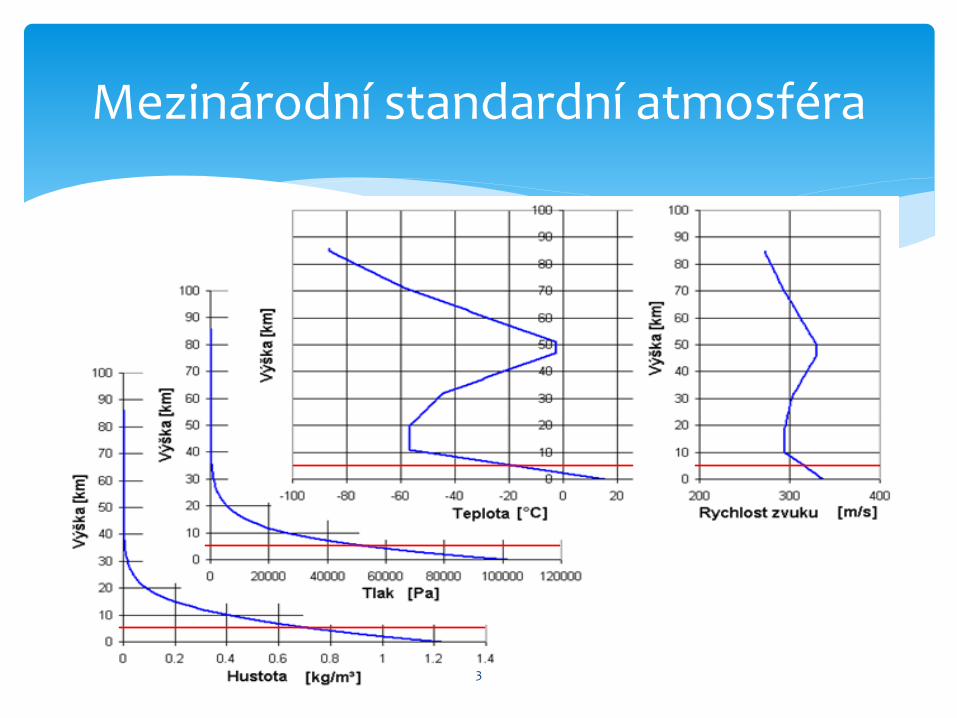
Mezinárodní standardní atmosféra
3
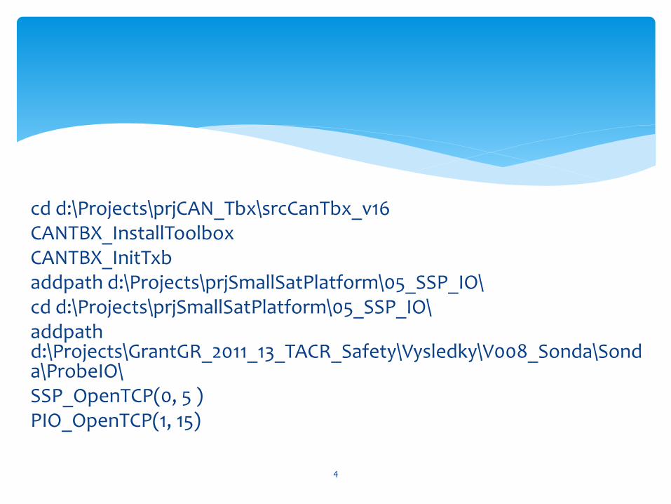
cd d:\Projects\prjCAN_Tbx\srcCanTbx_v16 CANTBX_InstallToolbox CANTBX_InitTxb addpath d:\Projects\prjSmallSatPlatform\05_SSP_IO\ cd d:\Projects\prjSmallSatPlatform\05_SSP_IO\ addpath d:\Projects\GrantGR_2011_13_TACR_Safety\Vysledky\V008_Sonda\Sonda\ProbeIO\ SSP_OpenTCP(0, 5 ) PIO_OpenTCP(1, 15)
4
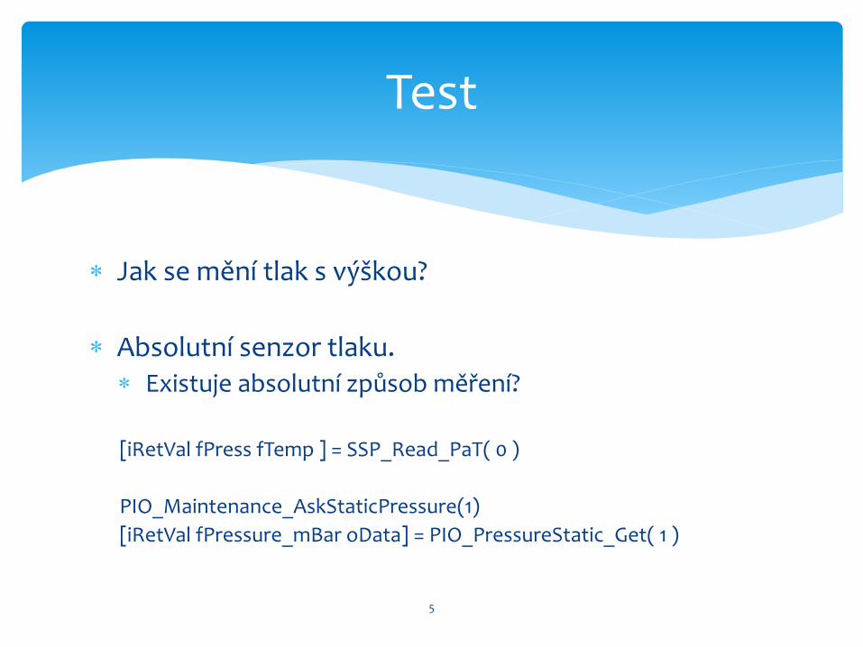
Jak se mění tlak s výškou?
Absolutní senzor tlaku. Existuje absolutní způsob měření?
[iRetVal fPress fTemp ] = SSP_Read_PaT( 0 )
PIO_Maintenance_AskStaticPressure(1)
[iRetVal fPressure_mBar oData] = PIO_PressureStatic_Get( 1 )
Test
5
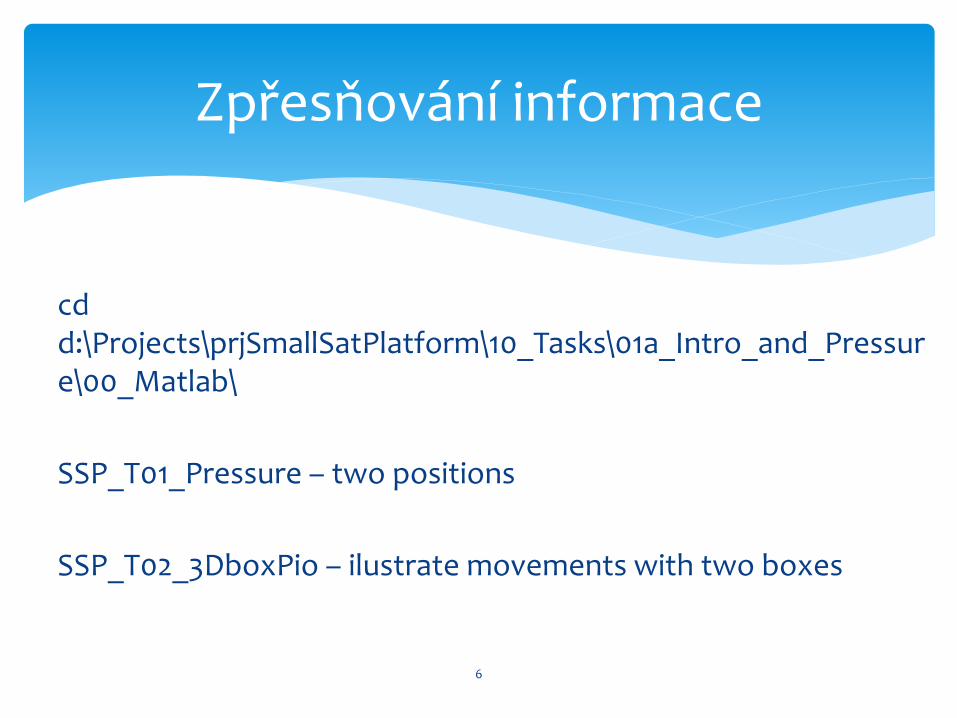
cd d:\Projects\prjSmallSatPlatform\10_Tasks\01a_Intro_and_Pressure\00_Matlab\
SSP_T01_Pressure – two positions
SSP_T02_3DboxPio – ilustrate movements with two boxes
6
Zpřesňování informace
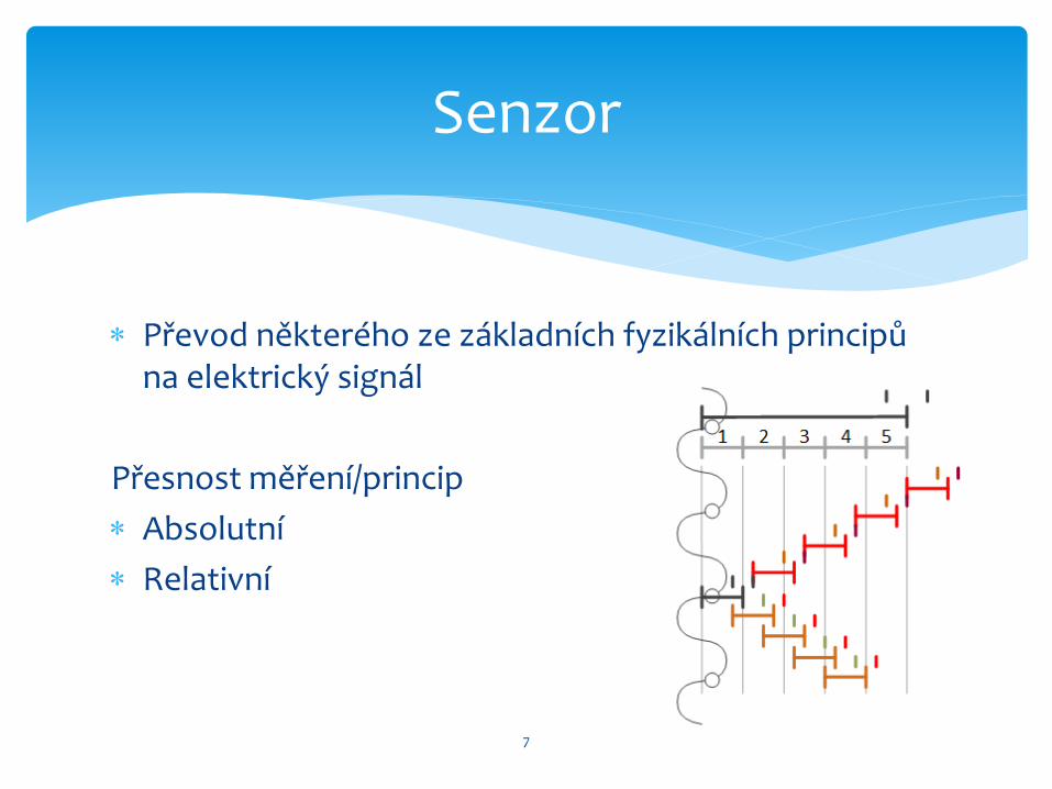
Převod některého ze základních fyzikálních principů na elektrický signál
Přesnost měření/princip
Absolutní
Relativní
Senzor
7
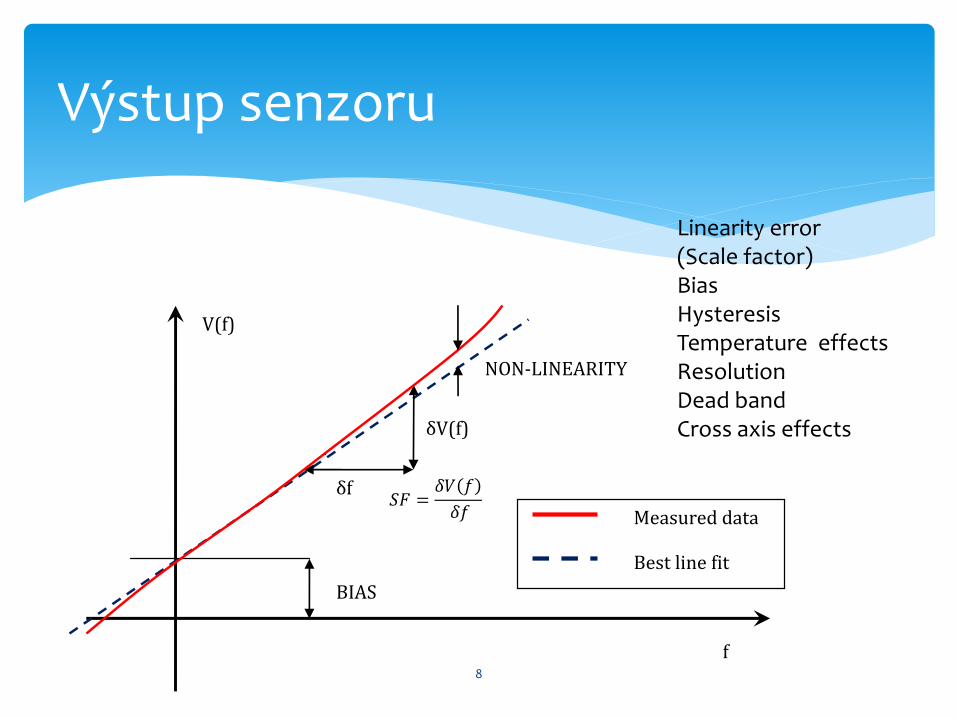
Výstup senzoru
BIAS
δf
δV(f)
NON-LINEARITY
Measured data
Best line fit
V(f)
f
Linearity error (Scale factor) Bias Hysteresis Temperature effects Resolution Dead band Cross axis effects
8
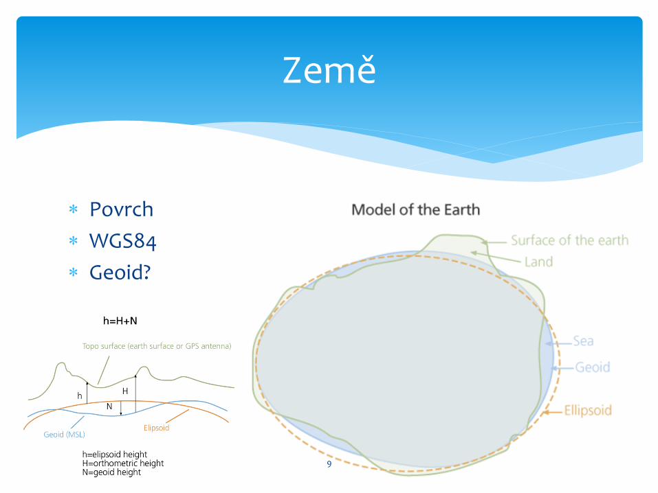
Povrch
WGS84
Geoid?
Země
9
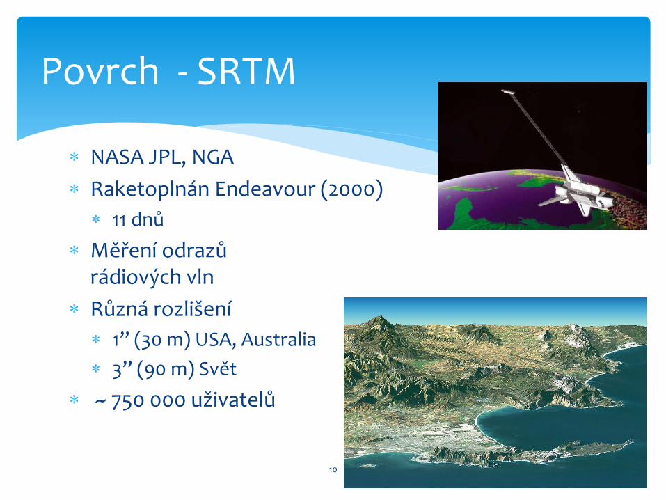
NASA JPL, NGA
Raketoplnán Endeavour (2000)
11 dnů
Měření odrazů rádiových vln
Různá rozlišení
1’’ (30 m) USA, Australia
3’’ (90 m) Svět
~ 750 000 uživatelů
Povrch - SRTM
10

Topografické podklady
Mapy
Hry
Simulace (povodně)
Navigace
Video
Využití
11
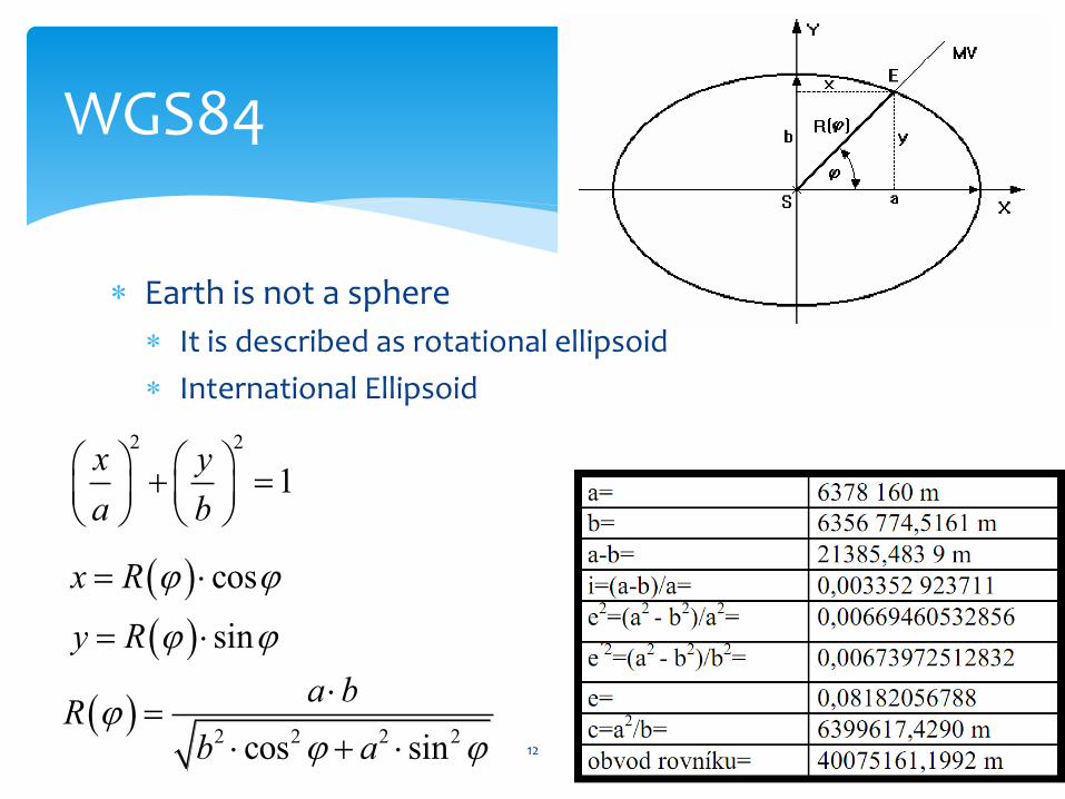
Earth is not a sphere
It is described as rotational ellipsoid
International Ellipsoid
WGS84
2 2
1x y
a b
cos
sin
x R
y R
2 2 2 2cos sin
a bR
b a
12
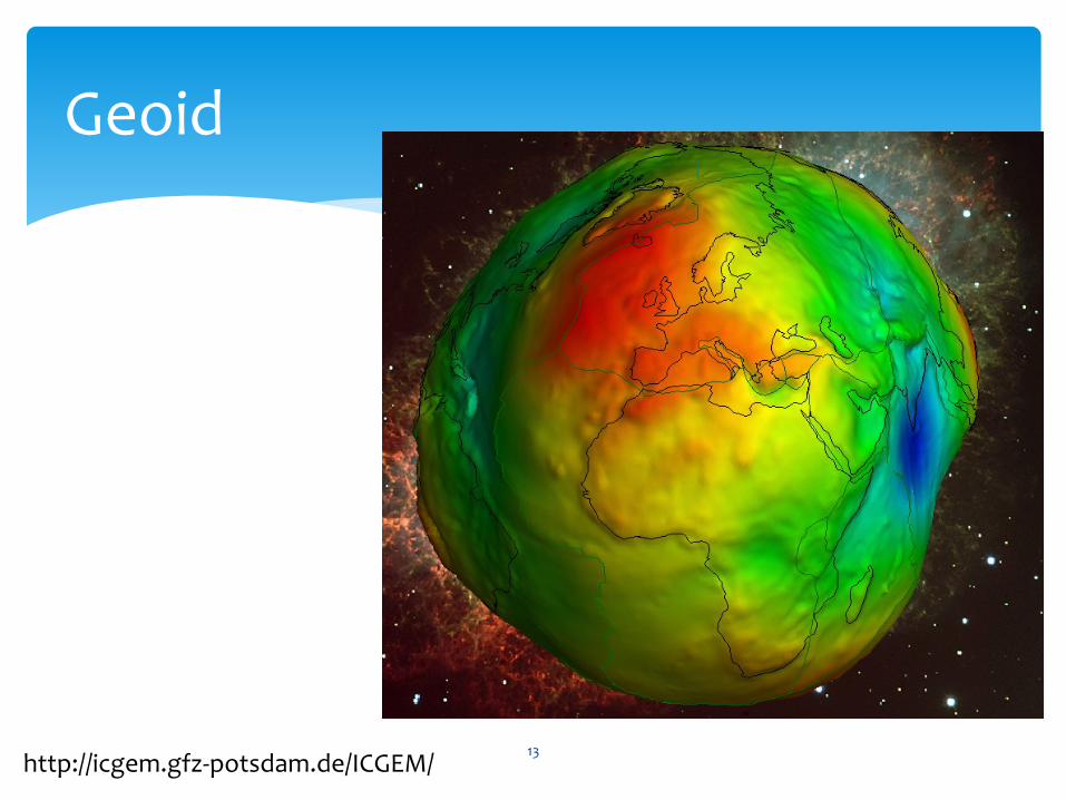
Geoid
http://icgem.gfz-potsdam.de/ICGEM/ 13
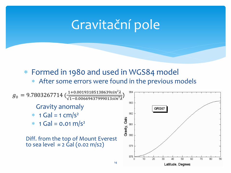
Formed in 1980 and used in WGS84 model After some errors were found in the previous models
Gravity anomaly 1 Gal = 1 cm/s² 1 Gal = 0.01 m/s²
Diff. from the top of Mount Everest to sea level ≈ 2 Gal (0.02 m/s2)
Gravitační pole
𝑔0 = 9.7803267714 (
1+0.00193185138639𝑠𝑖𝑛2𝜆
1−0.00669437999013𝑠𝑖𝑛2𝜆)
14
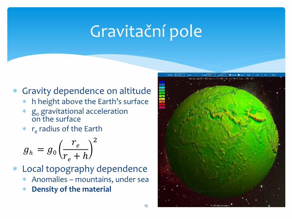
Gravity dependence on altitude h height above the Earth’s surface g0 gravitational acceleration
on the surface re radius of the Earth
Local topography dependence Anomalies – mountains, under sea Density of the material
Gravitační pole
𝑔ℎ = 𝑔0
𝑟𝑒
𝑟𝑒 + ℎ
2
15
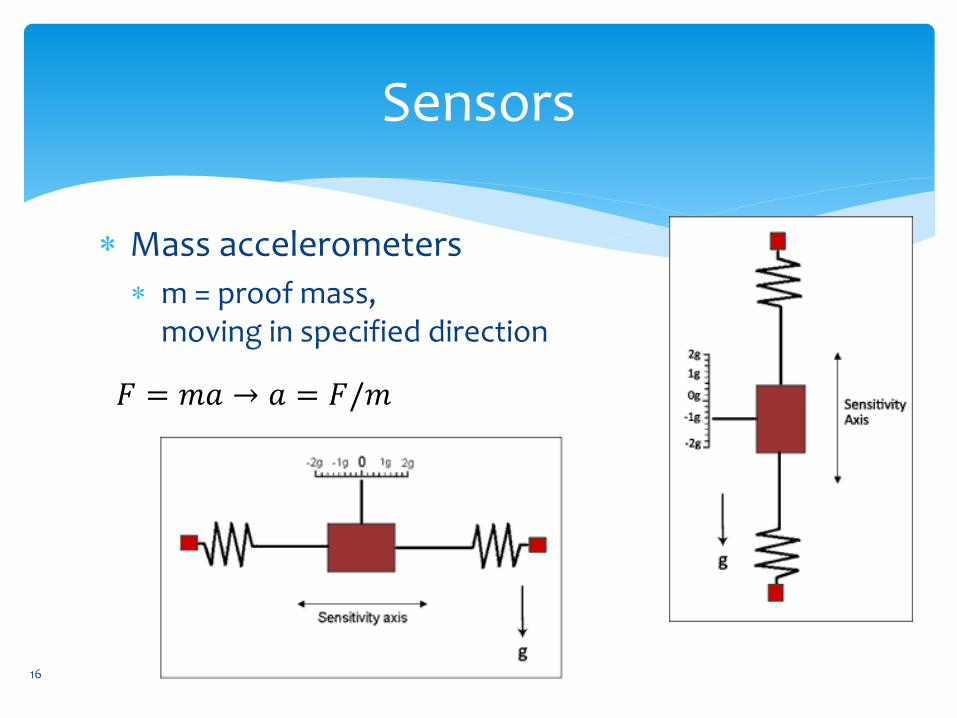
Sensors
Mass accelerometers
m = proof mass, moving in specified direction
16
𝐹 = 𝑚𝑎 → 𝑎 = 𝐹/𝑚
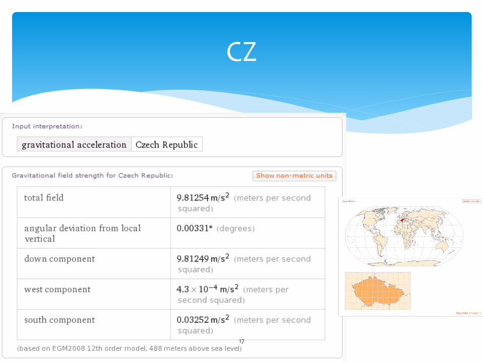
CZ
17
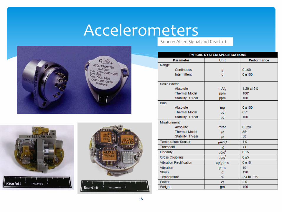
Accelerometers
Source: Allied Signal and Kearfott
18
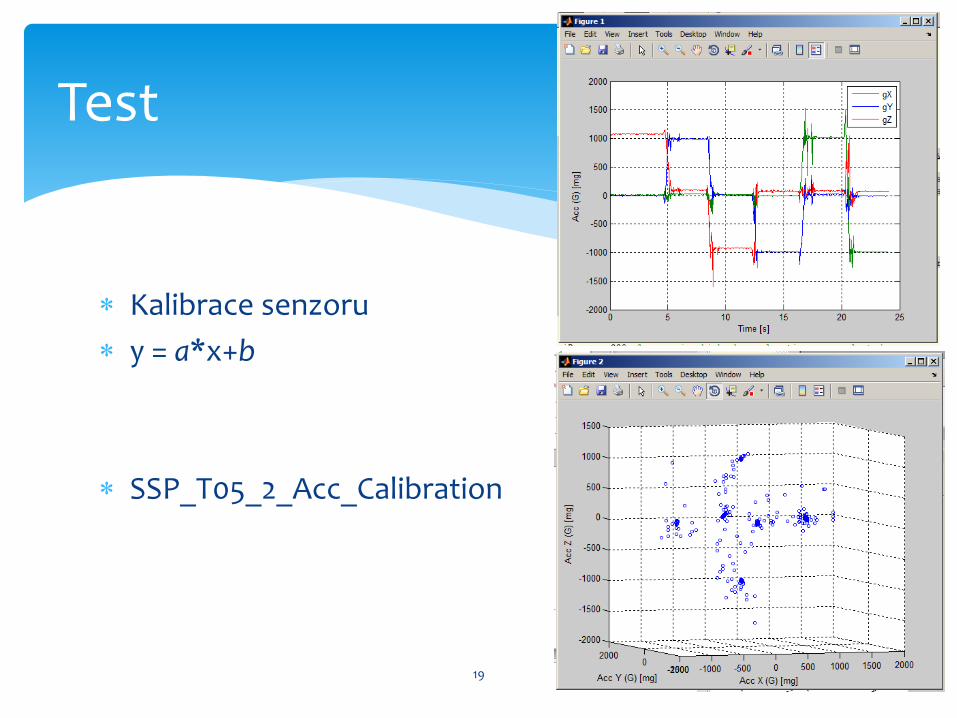
Kalibrace senzoru
y = a*x+b
SSP_T05_2_Acc_Calibration
Test
19

Polohové úhly
• Axes conventions
• Position angles
– Theta , θ, pitch – podélný sklon
– Phi , φ, roll – příčný náklon
– Psi , ψ, yaw, heading, azimuth – kurz
– Body frame – connected to the airplane
– Navigation frame – what is the reference for this?
, ,
, ,
,
20
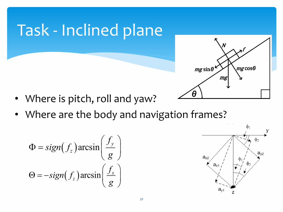
Task - Inclined plane
• Where is pitch, roll and yaw?
• Where are the body and navigation frames?
arcsin y
z
fsign f
g
arcsin xz
fsign f
g
21
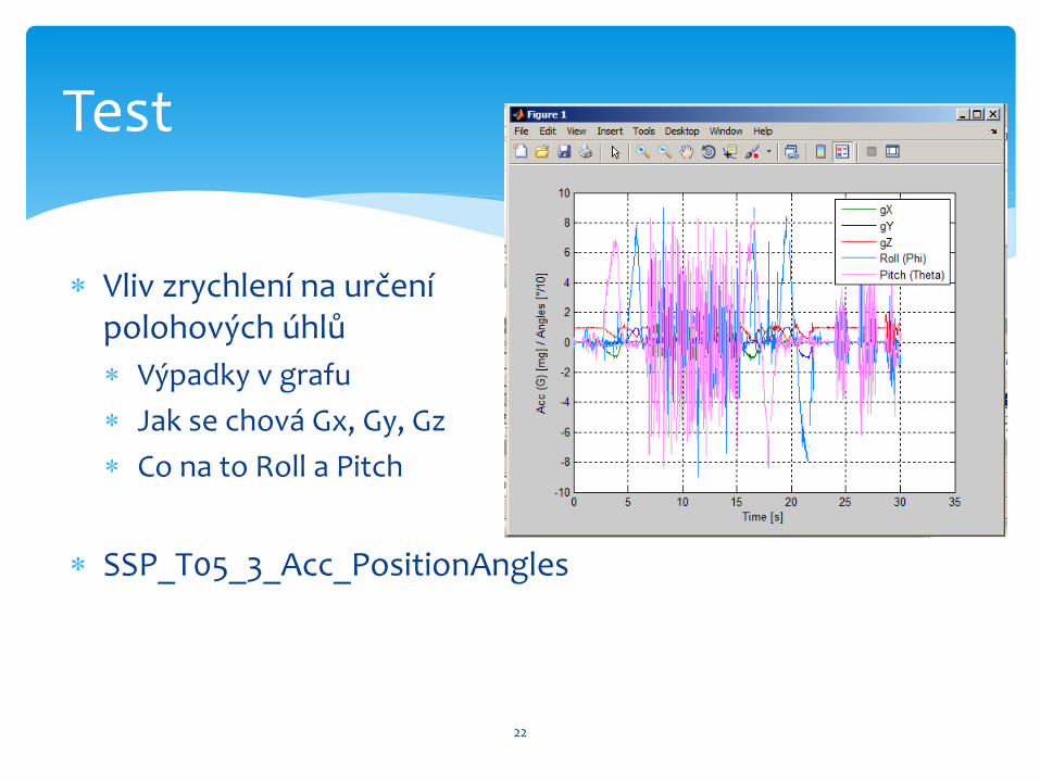
Vliv zrychlení na určení polohových úhlů
Výpadky v grafu
Jak se chová Gx, Gy, Gz
Co na to Roll a Pitch
SSP_T05_3_Acc_PositionAngles
Test
22
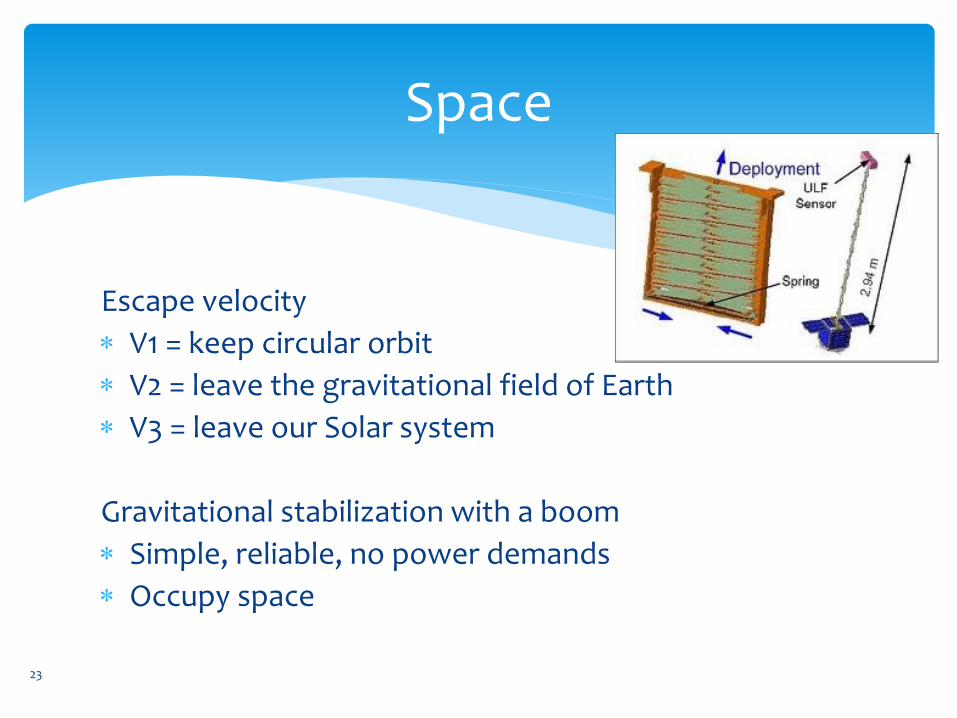
Space
Escape velocity
V1 = keep circular orbit
V2 = leave the gravitational field of Earth
V3 = leave our Solar system
Gravitational stabilization with a boom
Simple, reliable, no power demands
Occupy space
23
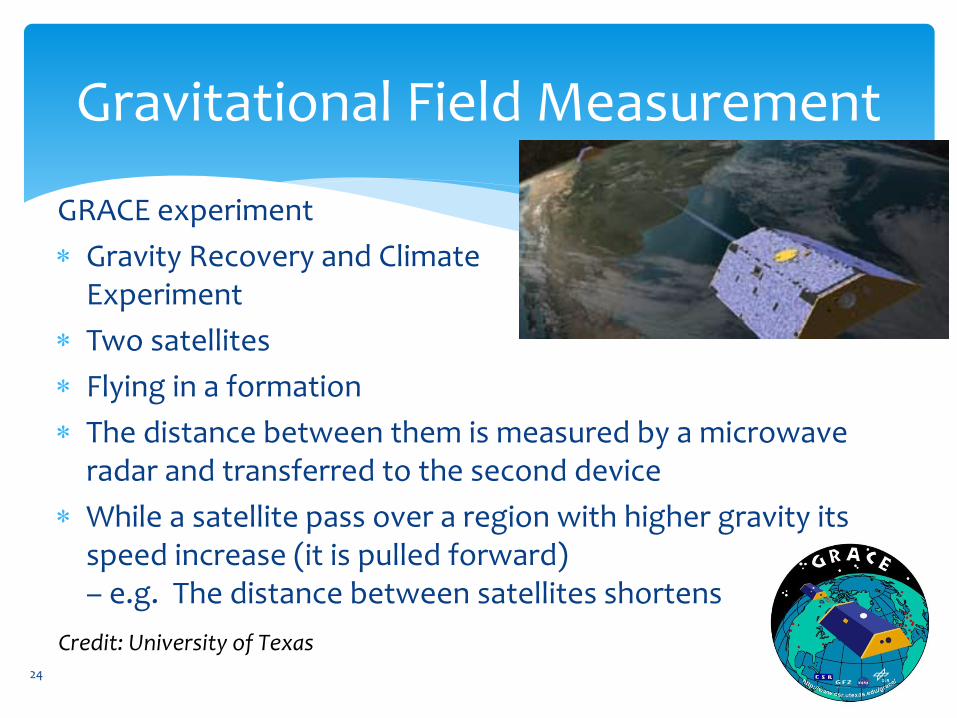
Gravitational Field Measurement
GRACE experiment
Gravity Recovery and Climate Experiment
Two satellites
Flying in a formation
The distance between them is measured by a microwave radar and transferred to the second device
While a satellite pass over a region with higher gravity its speed increase (it is pulled forward) – e.g. The distance between satellites shortens
24
Credit: University of Texas
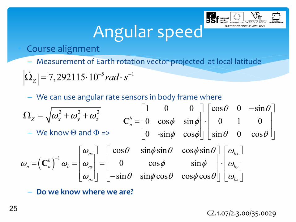
Angular speed • Course alignment
– Measurement of Earth rotation vector projected at local latitude
– We can use angular rate sensors in body frame where
– We know and =>
– Do we know where we are?
25
2 2 2
Z x y z
5 17,292115 10Z rad s
1 0 0 cos 0 sin
0 cos sin 0 1 0
0 -sin cos sin 0 cos
b
n
C
1
cos sin sin cos sin
0 cos sin
sin sin cos cos cos
nx bx
b
n n b ny by
nz bz
C
CZ.1.07/2.3.00/35.0029
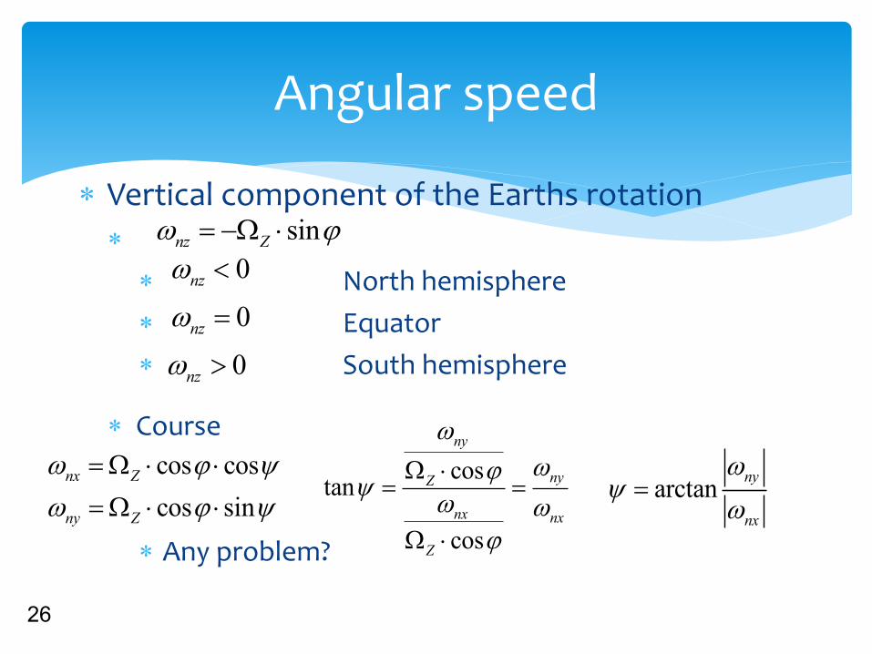
Angular speed
Vertical component of the Earths rotation
North hemisphere
Equator
South hemisphere
Course
Any problem?
26
sinnz Z
0nz
0nz
0nz
cos cos
cos sin
nx Z
ny Z
costan
cos
ny
nyZ
nx nx
Z
arctanny
nx

Gyroscopes
Coriolis force
Oscillating beam experiences in-plane rotation
Coriolis force causes perpendicular vibrations
Devices: piezoelectric gyro, hemispherical resonator gyro, MEMS gyro
2C m F Ω v
27
CZ.1.07/2.3.00/35.0029
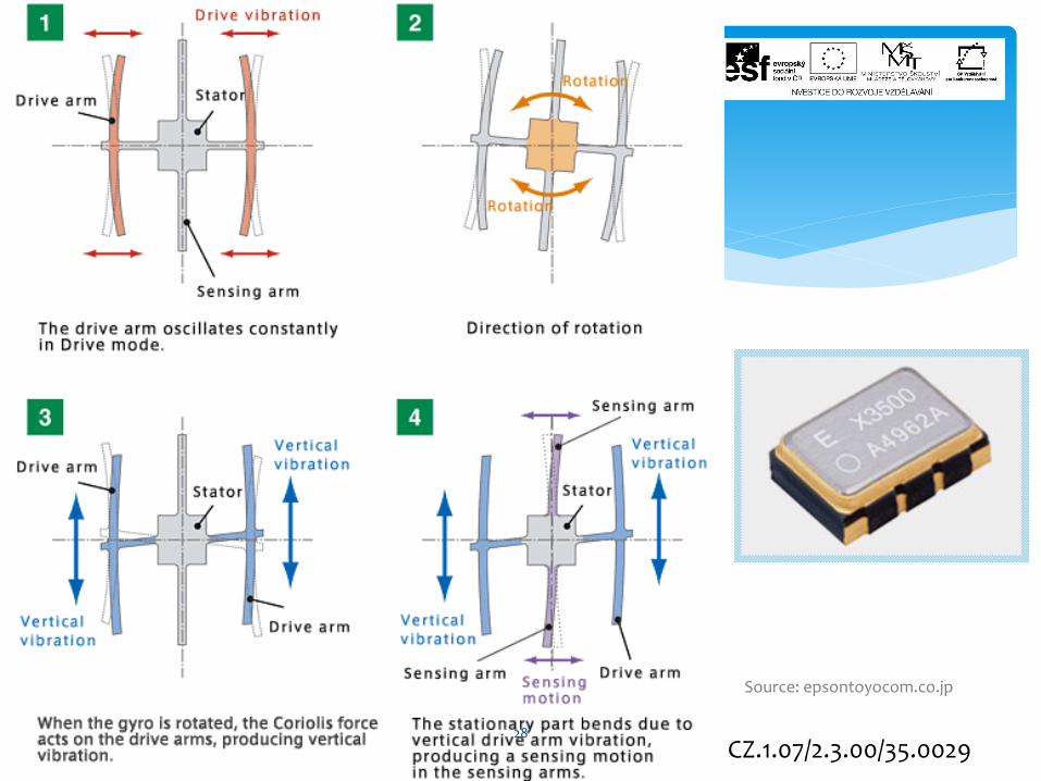
Source: epsontoyocom.co.jp
28
CZ.1.07/2.3.00/35.0029
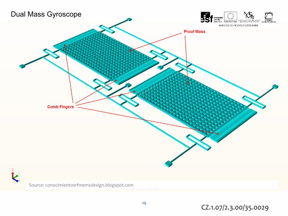
Dual Mass Gyroscope
Source: conocimientosrfmemsdesign.blogspot.com
29
CZ.1.07/2.3.00/35.0029

Dual Mass Gyroscope Video
Animation of transient simulation.
For clarity, the fixed electrodes and the comb drives are transparent and the thickness scaled by 2.
The displacement in Z is also scaled by a factor of 1 000,000 to allow the movement of the gyroscope to be resolved.
30

31
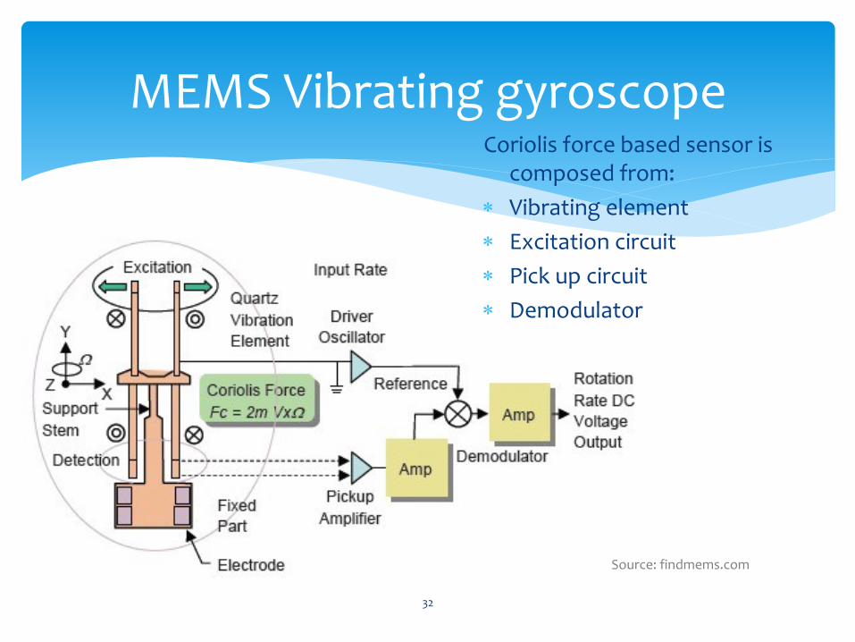
MEMS Vibrating gyroscope Coriolis force based sensor is
composed from:
Vibrating element
Excitation circuit
Pick up circuit
Demodulator
Source: findmems.com
32

Laser Gyroscope fundamentals
Light interference
Laser light is split to travel opposite directions around a circuit
Rotation -> path length differences
Devices:
ring laser gyro (RLG),
fiber optic gyro (FOG)
33
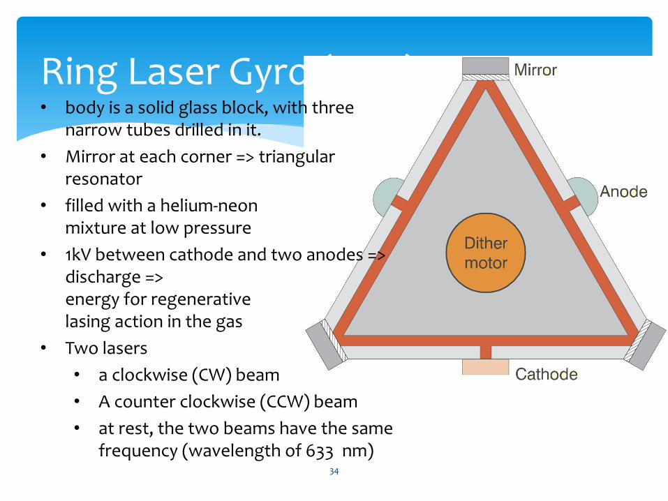
Ring Laser Gyro (RLG) • body is a solid glass block, with three
narrow tubes drilled in it.
• Mirror at each corner => triangular resonator
• filled with a helium-neon mixture at low pressure
• 1kV between cathode and two anodes => discharge => energy for regenerative lasing action in the gas
• Two lasers
• a clockwise (CW) beam
• A counter clockwise (CCW) beam
• at rest, the two beams have the same frequency (wavelength of 633 nm)
34
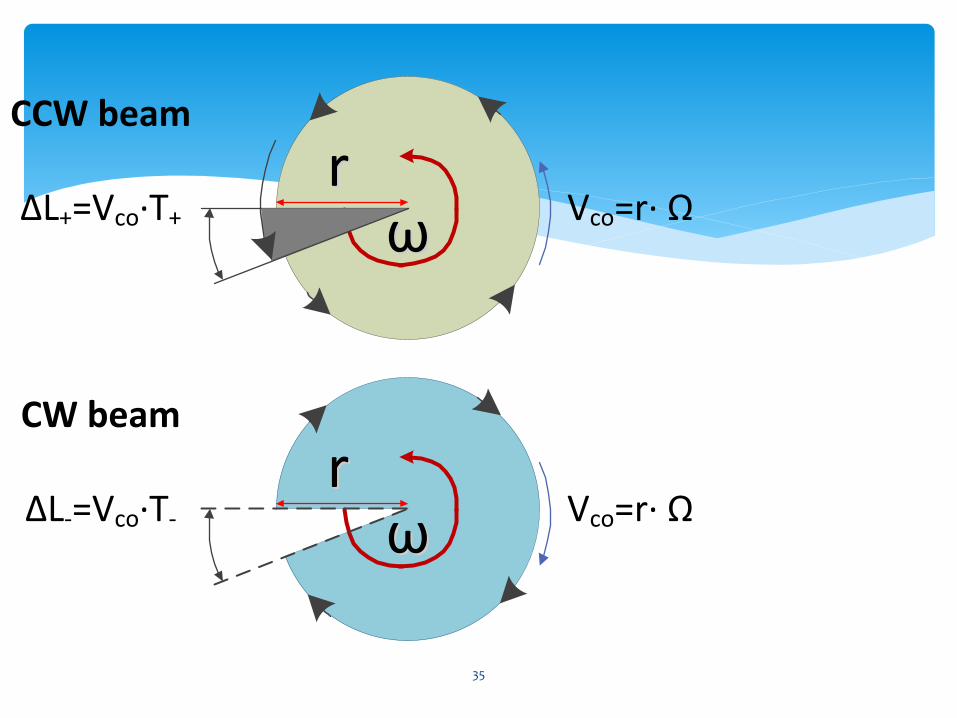
ωωrr
Vco=r· Ω ΔL+=Vco·T+
ωωrr
Vco=r· Ω ΔL-=Vco·T-
CCW beam
CW beam
35
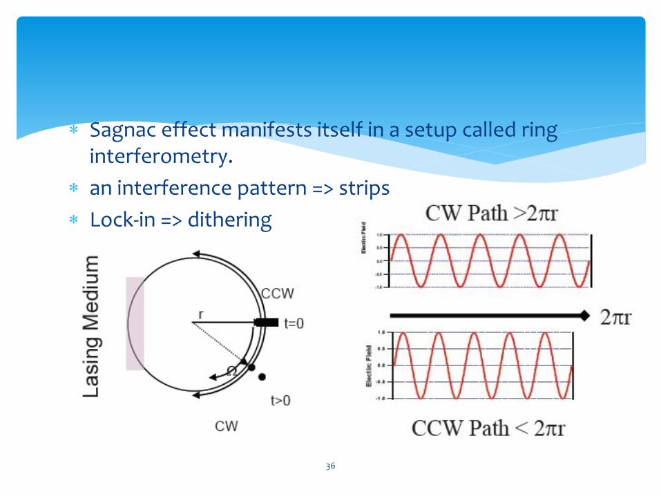
Sagnac effect manifests itself in a setup called ring interferometry.
an interference pattern => strips
Lock-in => dithering
36

The difference in path lengths causes a small difference in frequency
Samples of both beams can be extracted by semi-transparent mirror
frequency difference => proportional to the applied rotation rate
Problem => very low rotation rates => mirrors are not perfect => backscatter => lock, or dead band => dither motor - very small rotation (about 1 arc/minute peak, at about 400Hz) to the entire block.
37
CZ.1.07/2.3.00/35.0029
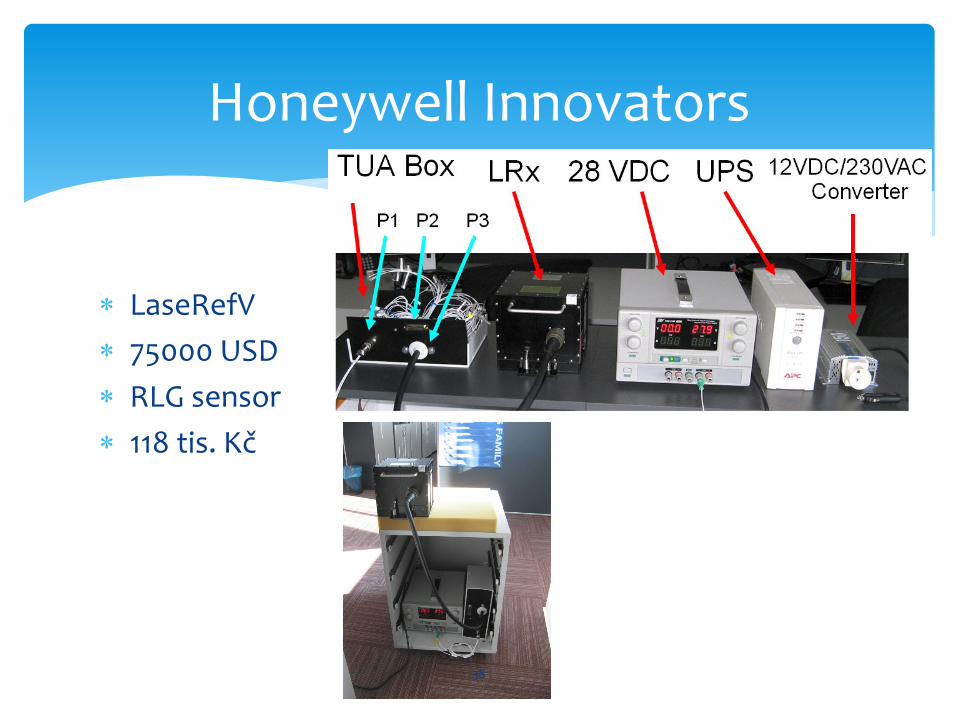
LaseRefV
75000 USD
RLG sensor
118 tis. Kč
Honeywell Innovators
38
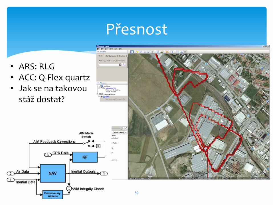
Přesnost
39
• ARS: RLG • ACC: Q-Flex quartz • Jak se na takovou
stáž dostat?
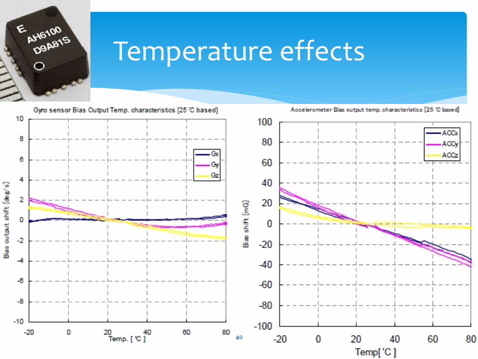
Temperature effects
40
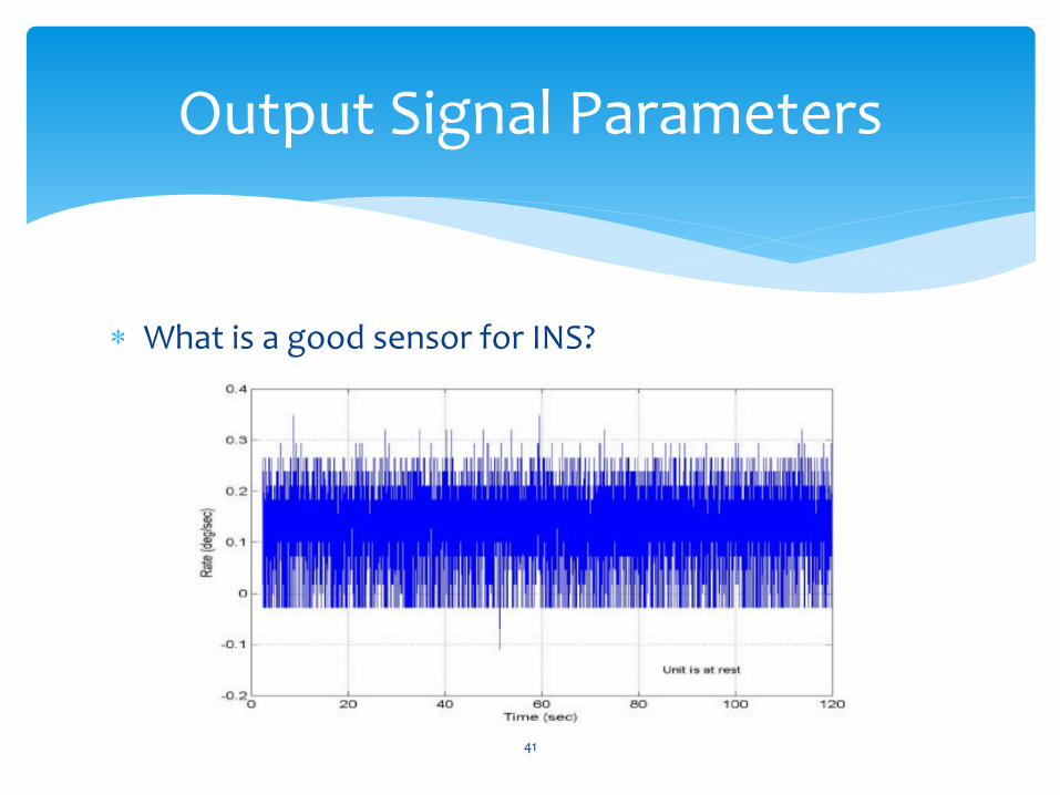
Output Signal Parameters
What is a good sensor for INS?
41
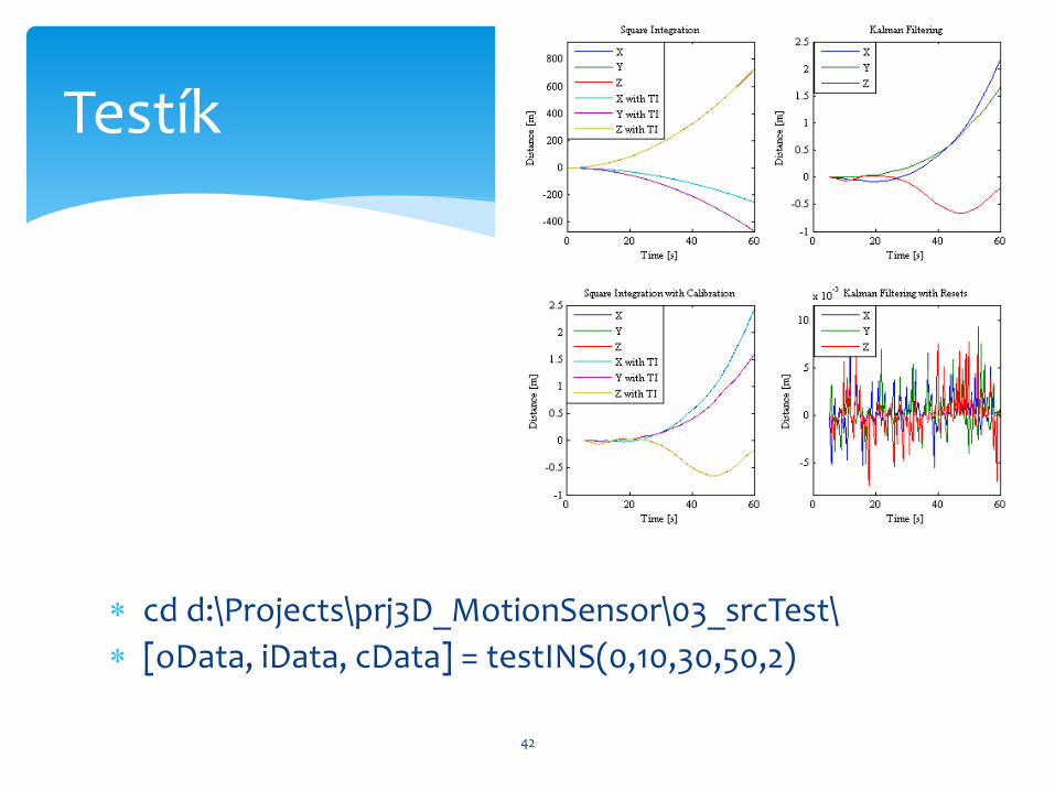
cd d:\Projects\prj3D_MotionSensor\03_srcTest\
[oData, iData, cData] = testINS(0,10,30,50,2)
Testík
42
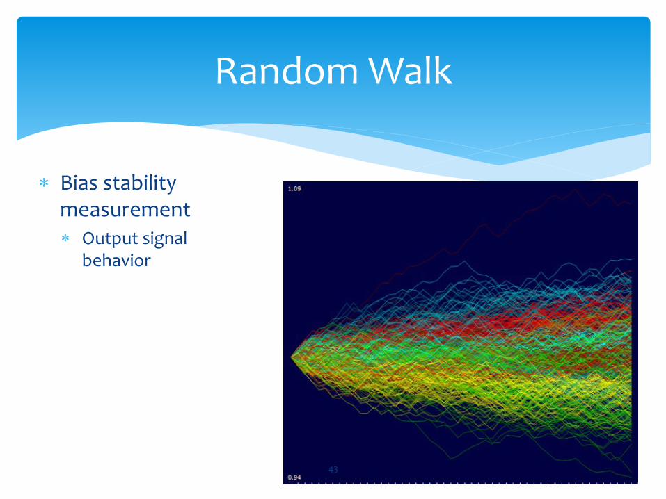
Random Walk
Bias stability measurement Output signal
behavior
43
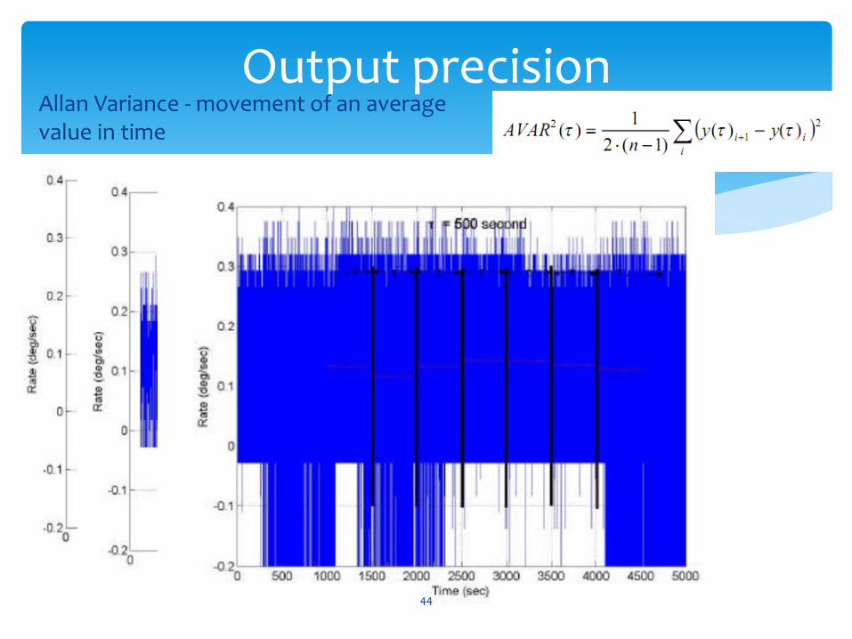
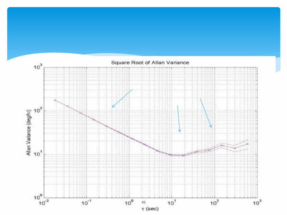
Output precision Allan Variance - movement of an average value in time
44
45

AVAR pro různé senzory
Method usage - all kinds of sensors
46

RLG vs MEMS
0 1 2 3 4 5 6
x 107
-0.5
0
0.5
1
1.5
2
2.5
3
ID 36, Body Roll Rate - 327 - logA429327
1.txt
Time [??]
Ma
dn
ess [?
?]
SDI
Body Roll Rate
SSM
P
Time [s]
Bo
dy
Ro
ll R
ate
[°/
s]
47
Pačes, P. - Popelka, J. - Levora, T.: Advanced Display and Position Angles Measurement Systems In: ICAS 2012 - 28th Congress of the International Council of the Aeronautical Sciences - Proceedings. Brisbane: ICAS - the International Council of the Aeronautical Science, 2012, p. P6.3.1-P6.3.14. ISBN 978-0-9565333-1-9.

Zpátky na Zem
48
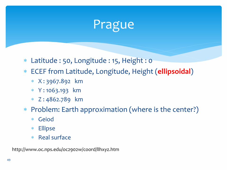
Prague
Latitude : 50, Longitude : 15, Height : 0
ECEF from Latitude, Longitude, Height (ellipsoidal) X : 3967.892 km
Y : 1063.193 km
Z : 4862.789 km
Problem: Earth approximation (where is the center?) Geiod
Ellipse
Real surface
49
http://www.oc.nps.edu/oc2902w/coord/llhxyz.htm

What happens if …
… we set LLH = [ 0, 0, 0 ]?
ECEF from Latitude, Longitude, Height (ellipsoidal)
X : 6378.137 km
Y : 0 km
Z : 0 km
50
http://www.oc.nps.edu/oc2902w/coord/llhxyz.htm
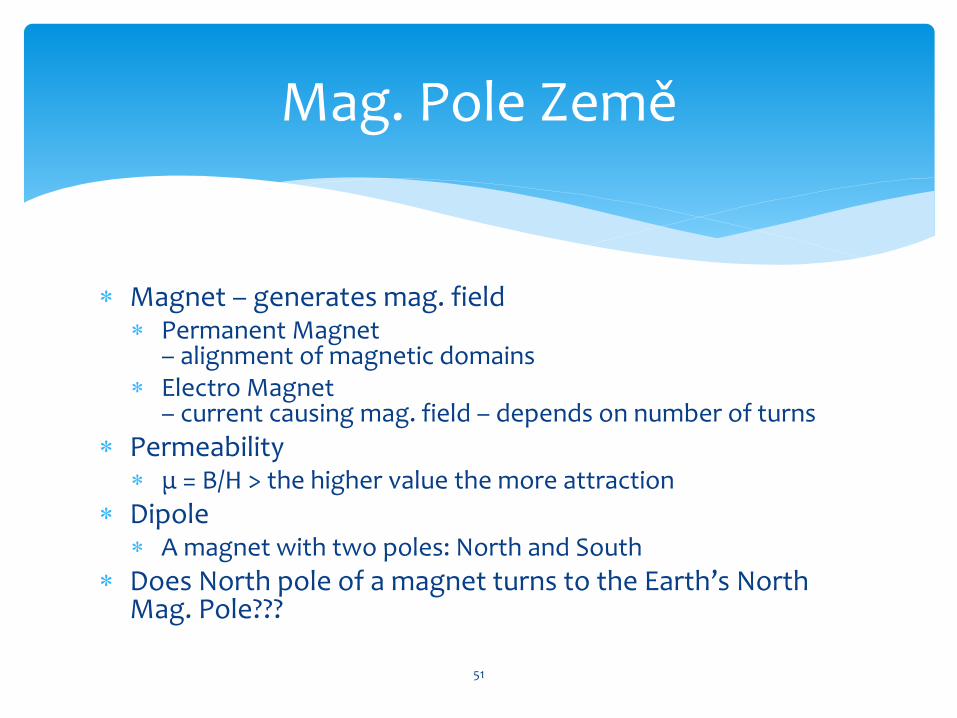
Magnet – generates mag. field Permanent Magnet
– alignment of magnetic domains Electro Magnet
– current causing mag. field – depends on number of turns
Permeability μ = B/H > the higher value the more attraction
Dipole A magnet with two poles: North and South
Does North pole of a magnet turns to the Earth’s North Mag. Pole???
Mag. Pole Země
51

Earth’s Magnetic Field
Almost a dipole : plus and minus, North and South
Confusion – double North Geographic North Pole (True North)
Magnetic North Pole Almost dipole
11° from rotation axis
Mag. Field Horizontal at equator, vertical at poles
Used for navigation from 12 century
Compasses N = North seeking
S = South seeking
52
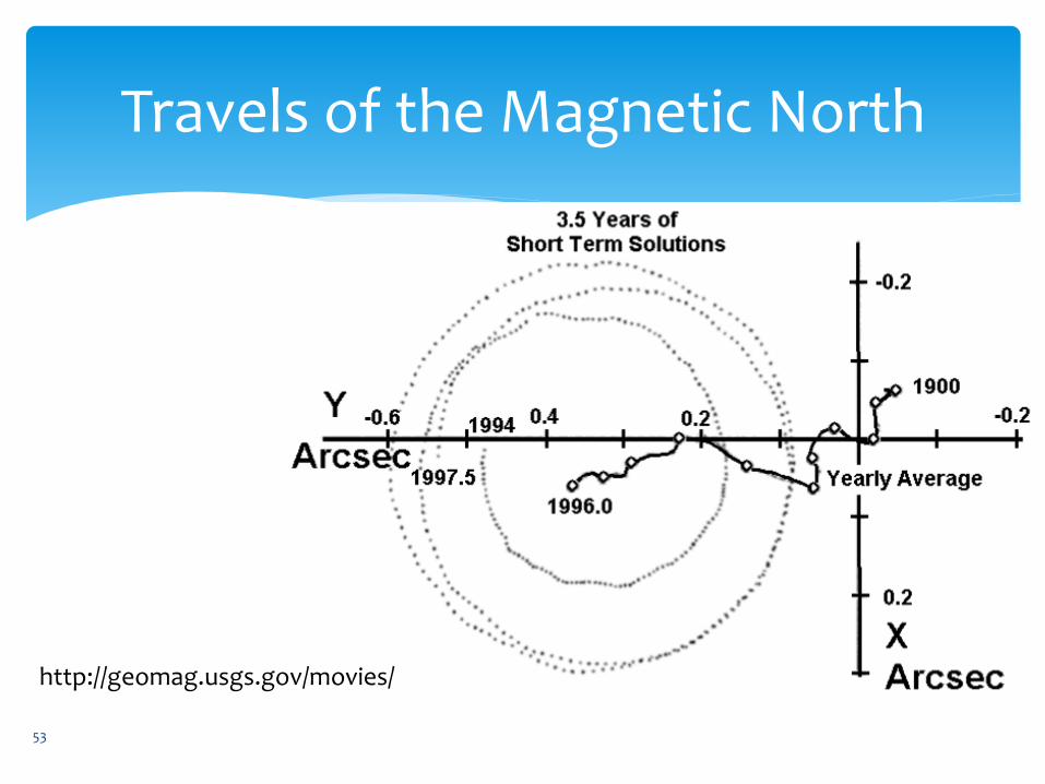
Travels of the Magnetic North
53
http://geomag.usgs.gov/movies/
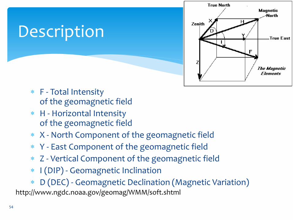
Description
F - Total Intensity of the geomagnetic field
H - Horizontal Intensity of the geomagnetic field
X - North Component of the geomagnetic field
Y - East Component of the geomagnetic field
Z - Vertical Component of the geomagnetic field
I (DIP) - Geomagnetic Inclination
D (DEC) - Geomagnetic Declination (Magnetic Variation)
54
http://www.ngdc.noaa.gov/geomag/WMM/soft.shtml
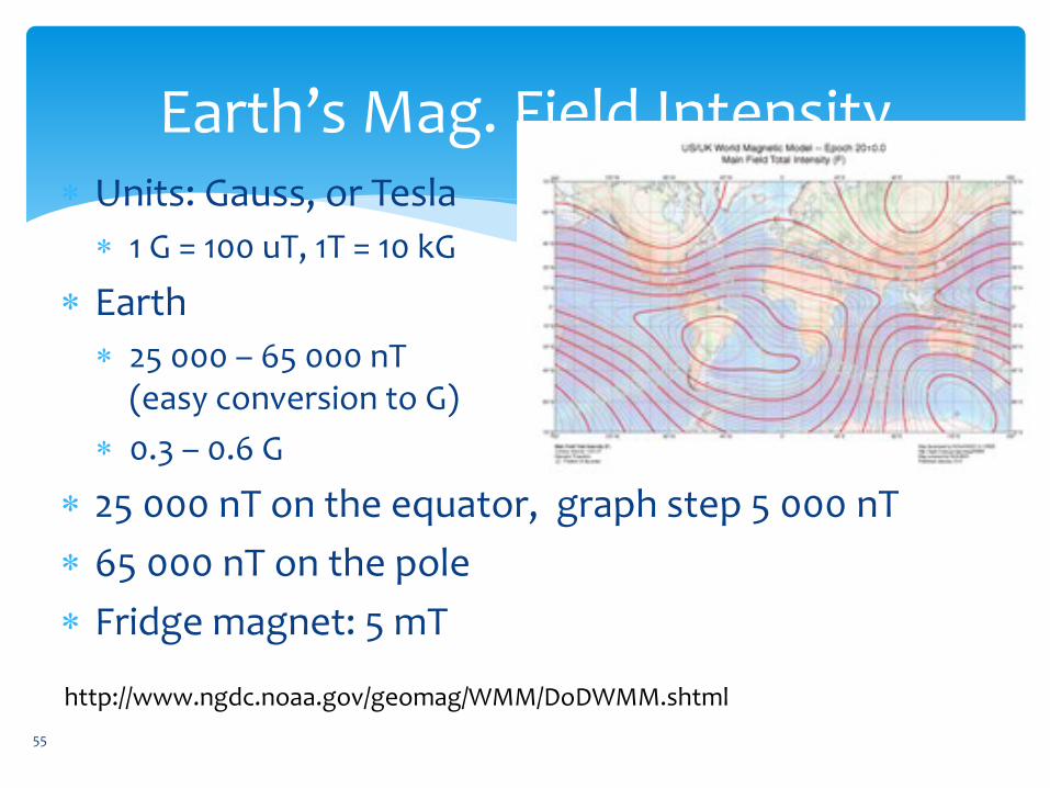
Earth’s Mag. Field Intensity Units: Gauss, or Tesla
1 G = 100 uT, 1T = 10 kG
Earth
25 000 – 65 000 nT (easy conversion to G)
0.3 – 0.6 G
25 000 nT on the equator, graph step 5 000 nT
65 000 nT on the pole
Fridge magnet: 5 mT
55
http://www.ngdc.noaa.gov/geomag/WMM/DoDWMM.shtml
56
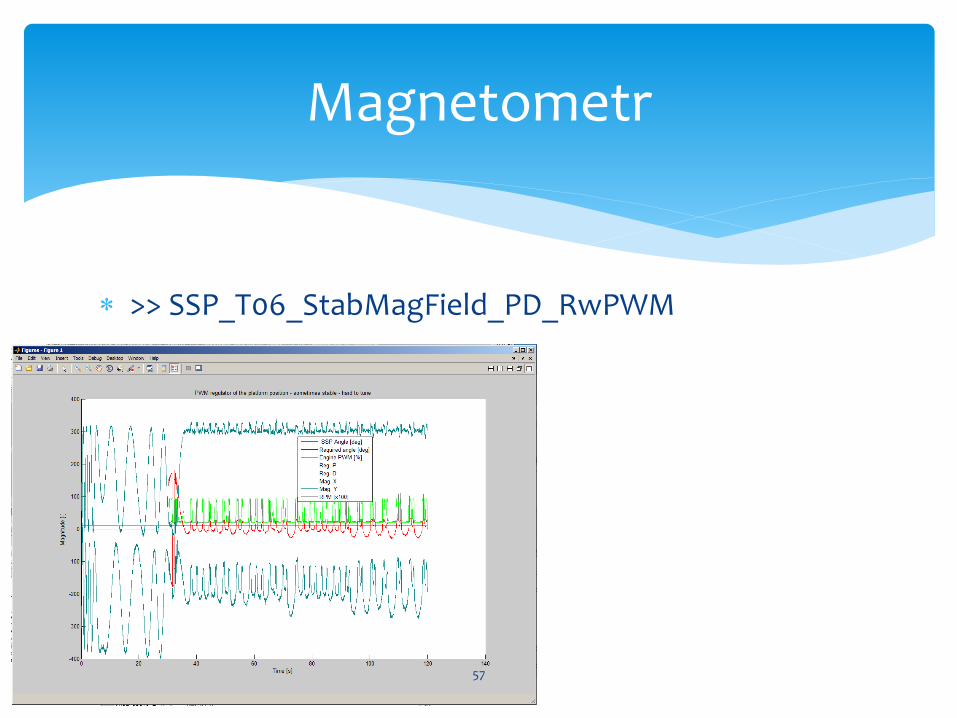
>> SSP_T06_StabMagField_PD_RwPWM
Magnetometr
57
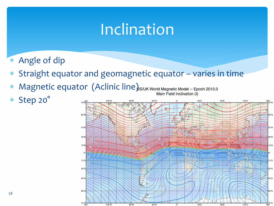
Inclination
58
Angle of dip
Straight equator and geomagnetic equator – varies in time
Magnetic equator (Aclinic line)
Step 20°
Sensors
Vector magnetometers allows to determine direction of the field
Fluxgate Resolution: 6 nT (nano Tesla)
Magneto-resistive – used for MEMS anisotropic magnetoresistance (AMR)
Resolution: 1 uT (mikro Tesla)
59
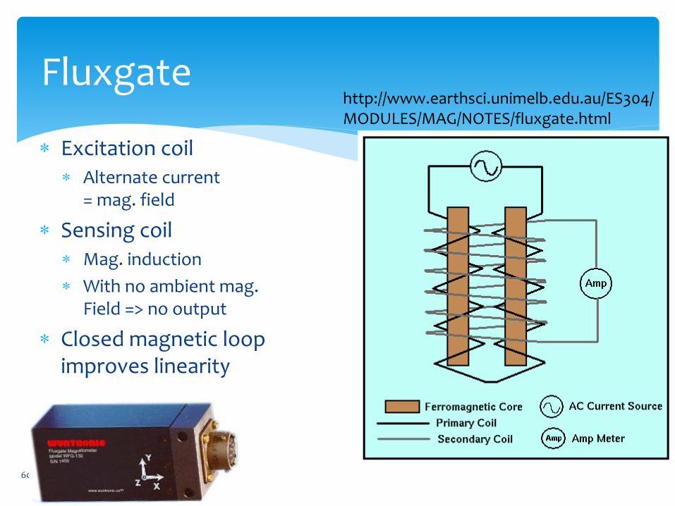
Fluxgate
Excitation coil Alternate current
= mag. field
Sensing coil Mag. induction
With no ambient mag. Field => no output
Closed magnetic loop improves linearity
60
http://www.earthsci.unimelb.edu.au/ES304/MODULES/MAG/NOTES/fluxgate.html
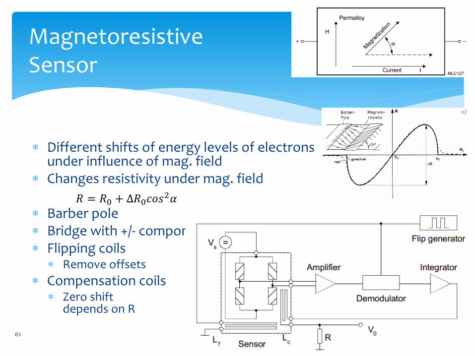
Magnetoresistive Sensor
Different shifts of energy levels of electrons under influence of mag. field
Changes resistivity under mag. field
Barber pole Bridge with +/- component orientation Flipping coils
Remove offsets
Compensation coils Zero shift
depends on R
61
𝑅 = 𝑅0 + Δ𝑅0𝑐𝑜𝑠2𝛼
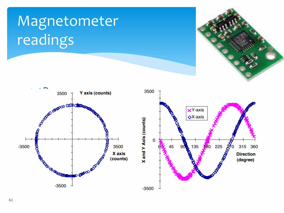
Magnetometer readings
2D compass
62
S/C Magnetometer
Placed outside of the spacecraft on a boom
In-flight calibration:
Spin stabilized S/C – allows to determine 8 of 12 calibration parameters
3D stabilized S/C – problem, we know the field magnitude from models
63
Spacecraft Stabilization
Magnetorquer (Rod)
Interact with the Earth’s mag. field the higher the craft flies the weaker field
(e.g. suitable for low Earth Orbits).
Lock problem (one axe aligned with the Earth’s field)
Switching current in a coil
Three perpendicular coils - no moving parts
Just electricity needed – no propellant required
It influences the magnetometer
The bigger craft the more current and intensity needed
Slow changes – not suitable for precise attitude control – allows dumping of reaction wheels
64
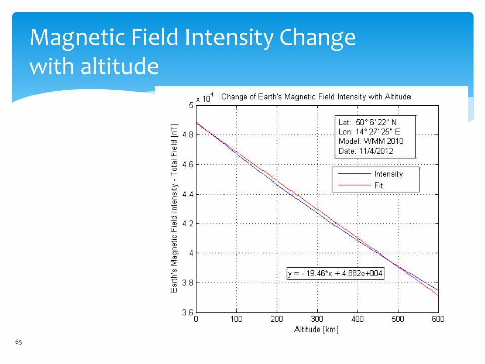
Magnetic Field Intensity Change with altitude
65
Image credit: Pavel Paces
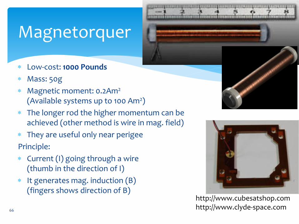
Magnetorquer
Low-cost: 1000 Pounds
Mass: 50g
Magnetic moment: 0.2Am2 (Available systems up to 100 Am2)
The longer rod the higher momentum can be achieved (other method is wire in mag. field)
They are useful only near perigee
Principle:
Current (I) going through a wire (thumb in the direction of I)
It generates mag. induction (B) (fingers shows direction of B)
66
http://www.cubesatshop.com http://www.clyde-space.com
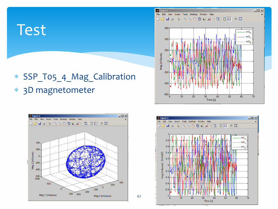
SSP_T05_4_Mag_Calibration
3D magnetometer
Test
67

Navigační systémy
68
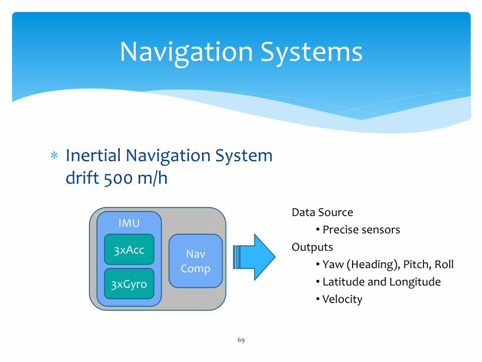
Navigation Systems
Inertial Navigation System drift 500 m/h
IMU
3xAcc
3xGyro
Data Source
• Precise sensors
Outputs
• Yaw (Heading), Pitch, Roll
• Latitude and Longitude
• Velocity
Nav Comp
69
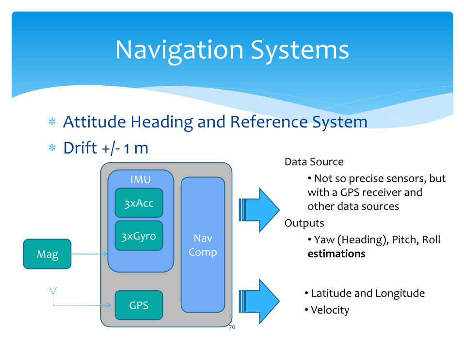
Navigation Systems
Attitude Heading and Reference System
Drift +/- 1 m
IMU
3xAcc
3xGyro
Data Source
• Not so precise sensors, but with a GPS receiver and other data sources
Outputs
• Yaw (Heading), Pitch, Roll estimations
GPS • Latitude and Longitude
• Velocity
Mag
Nav Comp
70

Flat Earth Navigator
The basic navigation algorithm
Example: table movement
71

Jak se uplatňuje drift
cd d:\Projects\prj3D_MotionSensor\03_srcTest\
[oData, iData, cData] = testINS(0,10,30,50,2)
Testík
72

Data rotation
Why are there ARS?
SSP_T05_5_Mag_Independence.m
Test
73
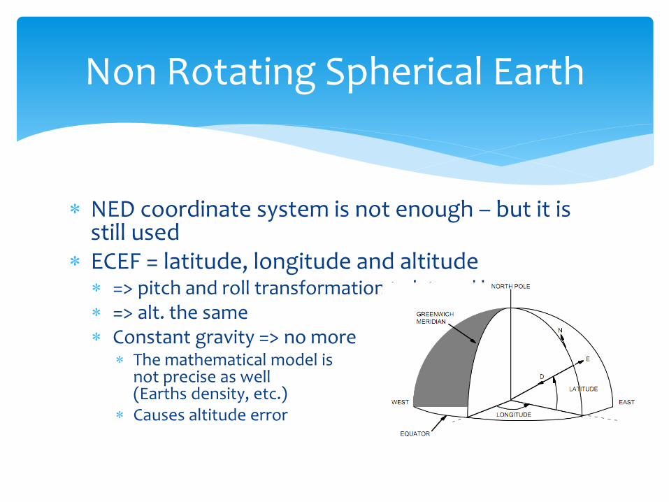
Non Rotating Spherical Earth
NED coordinate system is not enough – but it is still used
ECEF = latitude, longitude and altitude => pitch and roll transformation to lat. and lon. => alt. the same Constant gravity => no more
The mathematical model is not precise as well (Earths density, etc.)
Causes altitude error
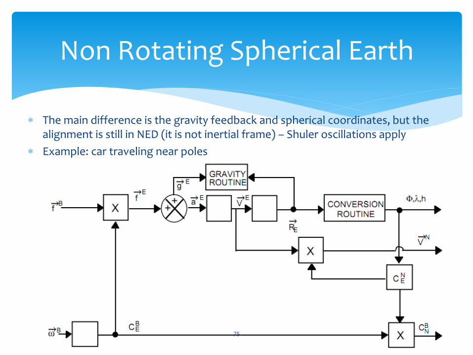
Non Rotating Spherical Earth
The main difference is the gravity feedback and spherical coordinates, but the alignment is still in NED (it is not inertial frame) – Shuler oscillations apply
Example: car traveling near poles
75
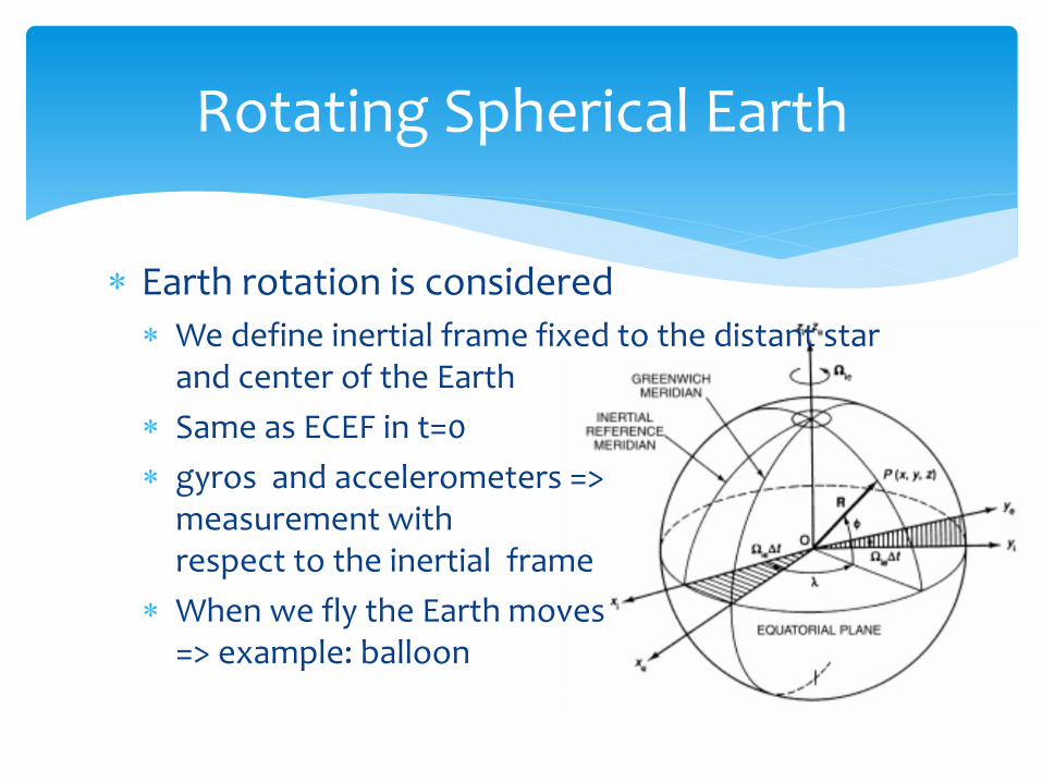
Rotating Spherical Earth
Earth rotation is considered
We define inertial frame fixed to the distant star and center of the Earth
Same as ECEF in t=0
gyros and accelerometers => measurement with respect to the inertial frame
When we fly the Earth moves => example: balloon

77
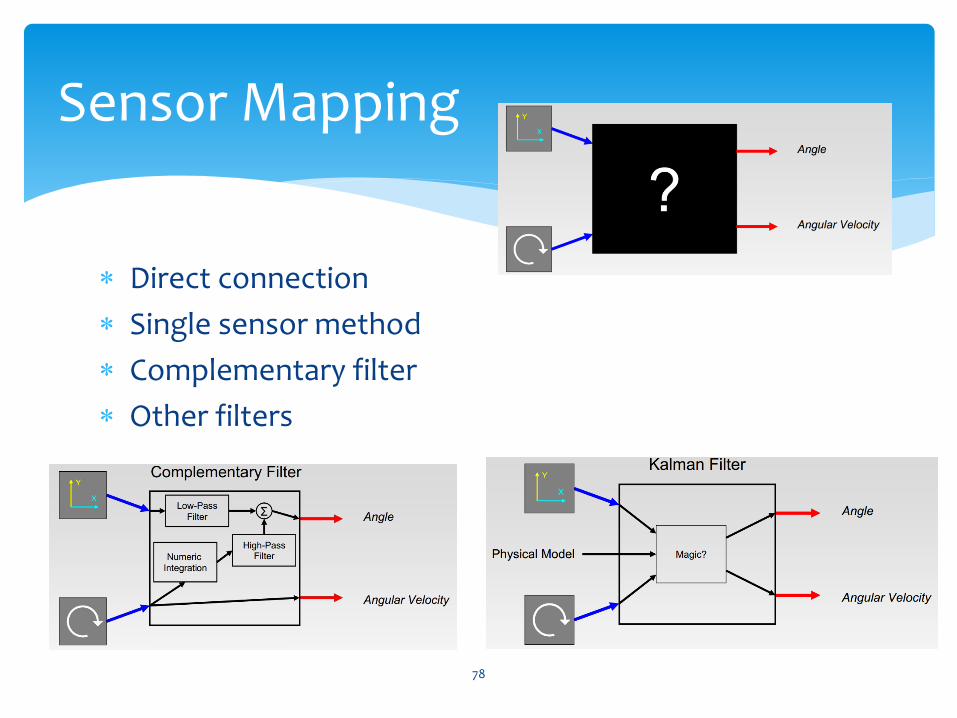
Sensor Mapping
Direct connection
Single sensor method
Complementary filter
Other filters
78
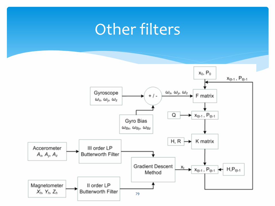
Other filters
79
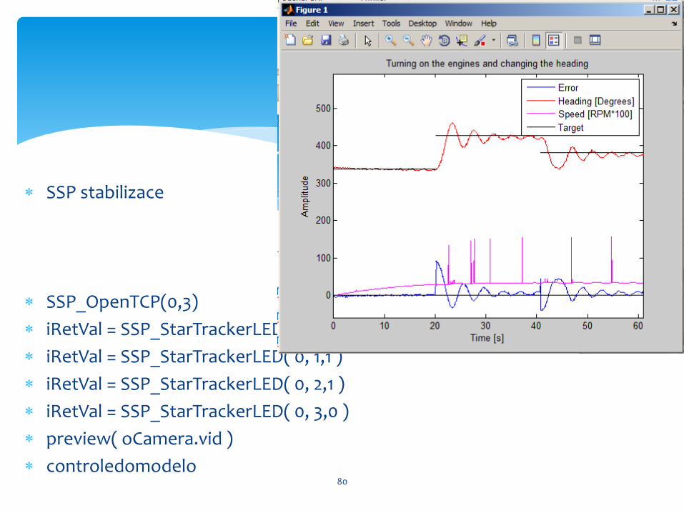
SSP stabilizace
SSP_OpenTCP(0,3)
iRetVal = SSP_StarTrackerLED( 0, 0,1 )
iRetVal = SSP_StarTrackerLED( 0, 1,1 )
iRetVal = SSP_StarTrackerLED( 0, 2,1 )
iRetVal = SSP_StarTrackerLED( 0, 3,0 )
preview( oCamera.vid )
controledomodelo 80

Senzory
Akční členy
Kalibrace výrazně zlepšuje užitné vlastnosti produktu
Mapy (SRTM)
Modely (GRACE)
Závěrem
81
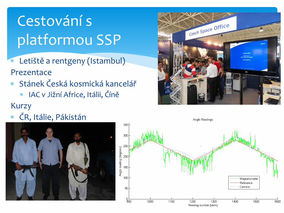
Letiště a rentgeny (Istambul)
Prezentace
Stánek Česká kosmická kancelář IAC v Jižní Africe, Itálii, Číně
Kurzy
ČR, Itálie, Pákistán
82
Cestování s platformou SSP

Bezdrátová platforma pro přenos dat
SSP, 3D box, SP82box – sonda
Celkem 11 lab. Úloh
Idea z NASA Ames Research Center
Několik prezentací v zahraničí
Nový systém pro měření polohových úhlů
Přesnost 1° dlouhodobě
Letové testy
83
Aktivity

Realizace
Dva absolutní senzory
Dva objemy
Testy
Laboratoř
Tunel
84
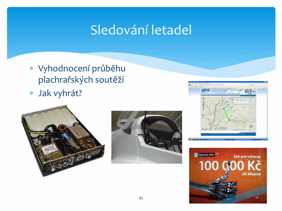
Vyhodnocení průběhu plachrařských soutěží
Jak vyhrát?
85
Sledování letadel

Letní stáže
Bak. a diplomové práce
Ph.D. studium
Další projekty
0 5 10 15 20 25 30 35-5
-4
-3
-2
-1
0
1
2
3
4
5x 10
-3
Normalized Total Port Reading Dependency on the Probe Angle of Attack
Angle of Attack [°]
PD
iffere
ntia
l/PT
ota
l 0 m
/s [-]
v = 0m/s
v = 10m/s
v = 20m/s
v = 30m/s
v = 40m/s
A
B
CD
86