Embed Size (px)
Citation preview
Missouri University of Science and Technology Missouri University of Science and Technology
Scholars' Mine Scholars' Mine
Symposia on Turbulence in Liquids Chemical and Biochemical Engineering
01 Sep 1975
Separation of Low Reynolds Number Flows Around a Corner Separation of Low Reynolds Number Flows Around a Corner
T. Matsui
M. Hiramatsu
M. Hanaki
Follow this and additional works at: https://scholarsmine.mst.edu/sotil
Part of the Chemical Engineering Commons
Recommended Citation Recommended Citation Matsui, T.; Hiramatsu, M.; and Hanaki, M., "Separation of Low Reynolds Number Flows Around a Corner" (1975). Symposia on Turbulence in Liquids. 30. https://scholarsmine.mst.edu/sotil/30
This Article - Conference proceedings is brought to you for free and open access by Scholars' Mine. It has been accepted for inclusion in Symposia on Turbulence in Liquids by an authorized administrator of Scholars' Mine. This work is protected by U. S. Copyright Law. Unauthorized use including reproduction for redistribution requires the permission of the copyright holder. For more information, please contact [email protected].
SEPARATION OF LOW REYNOLDS NUMBER FLOW
AROUND A CORNER
T. Matsui, M. Hiramatsu and M. Hanaki
Gifu University
Kakamigahara, Gifu 504, Japan
ABSTRACT
I t was shown experimentally that low Reynolds
nunber flows around a sharp corner do not separate at
the corner, and separation points move downstream from
the corner with decrease in Reynolds number. For the
flow in a channel with a backward-facing step, the
experimental resu lts showed a good agreement with
those of numerical calcu lation for the position of
separation points and the length o f standing vortices.
INTRODUCTION
I t is usually thought that a real, viscous flow
around a sharp corner separates from the corner. How
ever, on the course of experimental studies o f the
mechanism of reattachment o f separated boundary layers,
i t was found that low Reynolds number flows around a
sharp corner made of two f la t plates did not separate
at the corner, but separated at a point downstream
from the corner. This phenomenon is contrary to the
usual idea of separation in a flow around a sharp
corner. The phenomenon of separation downstream from
a sharp corner was f i r s t found experimentally by Hama
(1965) in a backstep-type laminar supersonic flow. In
numerical studies of the flow in a channel with a back
ward-facing step, that is the case where the deflecting
angle is 90 degrees, Kawaguti (1965) shows a small
dotted lin e segment below the fu ll line indicating
d iv id ing streamline near the corner. I t was informed
by a private comnunication from Kawaguti that the
dotted lin e is the actual computed d ivid ing streamline,
as was conjectured by Roache and Mueller (1970). They
show a regular movement o f the separation point down
the base as the Reynolds number is decreased in their
numerical studies. Then, an experimental study of the
flow was made in order to confirm the movement of sepa
ration points with decrease in Reynolds nunber.
EXPERIMENTAL ARRANGEMENTS AND PROCEDURES
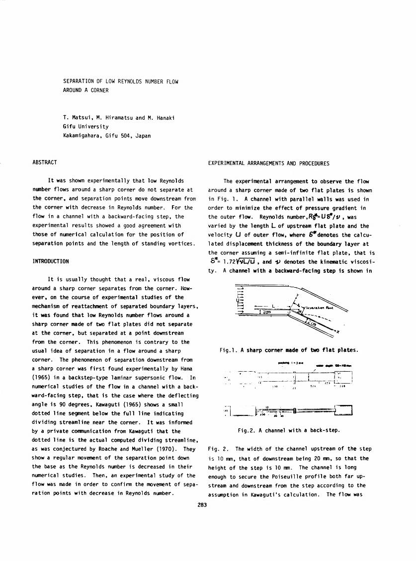
The experimental arrangement to observe the flow
around a sharp corner made o f two f la t plates is shown
in Fig. 1. A channel with para lle l w alls was used in
order to minimize the effect o f pressure gradient in
the outer flow. Reynolds number,R £ ± U f?/ iJ , was
varied by the length L of upstream f la t plate and the
ve locity U of outer flow, where 6 * denotes the calcu
lated displacement thickness o f the boundary layer at
the corner assuming a sem i-in fin ite f la t plate, that is
6*= 1 .7 2 V SU U , and V denotes the kinematic v is c o s i
ty. A channel with a backward-facing step is shown in
F ig . l. A sharp corner made of two f la t plates.
F ig .2. A channel with a back-step.
Fig. 2. The width o f the channel upstream of the step
is 10 mm, that of downstream being 20 inn, so that the
height o f the step is 10 ran. The channel is long
enough to secure the Po iseu ille p ro file both far up
stream and downstream from the step according to the
assumption in Kawaguti's calcu lation. The flow was
283
visua lized by the hydrogen bubble technique. Dye
method was also used to measure the posit ion of separa
tion on the wall downstream from the corner. Water was
used as a working f lu id for the flow around a sharp
corner made of two f la t p lates, whereas glycerin so lu
tion was used for the flow in a channel with a step as
lower Reynolds numbers were required to compare with
the calculated re su lts.
EXPERIMENTAL RESULTS AND DISCUSSIONS
Flow Around a Sharp Corner Made of Two F lat Plates
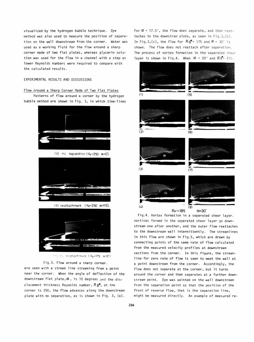
Patterns of flow around a corner by the hydrogen
bubble method are shown in Fig. 3, in which tim e-lines
(ci) no separation (R,-=250 a=iO)
i b) reattachment ( Rr=250 oc=V7.5)
' ' ■ ) r. r^ottach-Tv-nt ( R»--175 aOC)
F ig .3. Flow around a sharp corner,
are seen with a streak line streaming from a point
near the corner. When the angle o f deflection o f the
downstream f la t plate,o( , is 10 degrees and the d is
placement thickness Reynolds number, R §*, at the
corner is 250, the flow advances along the downstream
plate with no separation, as is shown in Fig. 3, (a).
For d = 17.5°, the flow does separate, and then reat
taches to the downstram plate, as seen in F ig .3 ,(b ).
In F ig .3 ,(c ), the flow for R ?f= 175 and = 30° is
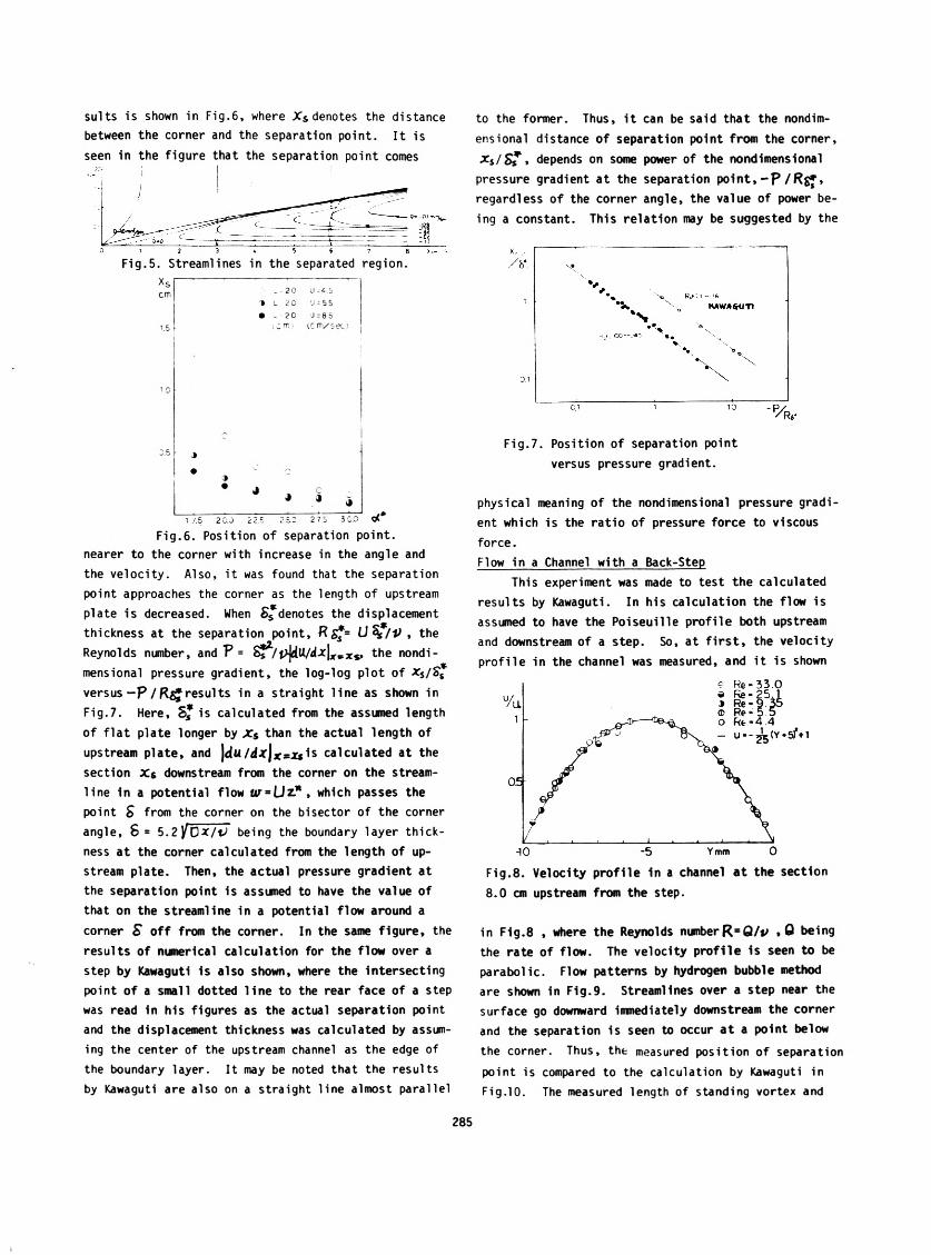
shown. The flow does not reattach a fte r separation.
The process of vortex formation in the separated shear
layer is shown in Fiq.4. When o( = 20° and R?f= 210,
(D (5)
( 2) (6)
(3) (7)
(A) (8)Rv =185 (X=30’
F ig .4. Vortex formation in a separated shear layer,
vortices formed in the separated shear layer go down
stream one after another, and the outer flow reattaches
to the downstream wall in term ittently. The streamlines
in th is flow are shown in F ig .5, which are drawn by
connecting points of the same rate o f flow calculated
from the measured ve locity p ro file s at downstream
sections from the corner. In th is figu re , the stream
lin e for zero rate of flow is seen to meet the wall at
a point downstream from the corner. Accordingly, the
flow does not separate at the corner, but i t turns
around the corner and then separates at a further down
stream point. Dye was painted on the wall downstream
from the separation point so that the position of the
front of reverse flow, that is the separation line ,
might be measured d irectly . An example of measured re-
284
su its is shown in F ig .6, where X s denotes the distance
between the corner and the separation point. I t is
seen in the figure that the separation point comes
F ig .5. Streamlines in the separated region.
x s r ^ -----------------------—cm 1 _ 2 0 J 5
4 L 2 C J = 5 5
• - 2 C 0 = 8 5
1.5 r- (cm .i i c m / s e o
j.b j
• c4
* J J iJ .* J1 7.5 2 0.J 2 2.5 2 5.0 2 75 i CO C < *
F ig .6. Position o f separation point,
nearer to the corner with increase in the angle and
the velocity. Also, i t was found that the separation
point approaches the corner as the length of upstream
plate is decreased. When 8*denotes the displacement
thickness at the separation point, R gf= the
Reynolds number, and V = S^2-/ v]AU/dx\XvXs, the nondi-
mensional pressure gradient, the log-log p lot of xs/S s
versus —P / resu lts in a stra ight line as shown in
F ig .7. Here, S * is calculated from the assumed length
of f la t plate longer by Xs than the actual length of
upstream plate, and \du/dx\ calculated at the
section X s downstream from the corner on the stream
line in a potential flow w = LJz.*, which passes the
point S from the corner on the bisector of the corner
angle, 8 = 5.2 l C * / b e i n g the boundary layer th ick
ness at the corner calculated from the length of up
stream plate. Then, the actual pressure gradient at
the separation point is assumed to have the value of
that on the streamline in a potential flow around a
corner S o ff from the corner. In the same figure, the
resu lts of nianerical calculation for the flow over a
step by Kawaguti is also shown, where the intersecting
point o f a small dotted lin e to the rear face of a step
was read in h is figures as the actual separation point
and the displacement thickness was calculated by assum
ing the center of the upstream channel as the edge of
the boundary layer. I t may be noted that the results
by Kawaguti are also on a stra igh t line almost parallel
to the former. Thus, i t can be said that the nondim
ens ional distance o f separation point from the corner,
* s / S T * depends on some power of the nondimensional
pressure gradient at the separation p o in t , - p / R g » ,
regardless o f the corner angle, the value of power be
ing a constant. This re lation may be suggested by the
F ig .7. Position of separation point
versus pressure gradient.
physical meaning of the nondimensional pressure grad i
ent which is the ra tio of pressure force to viscous
force.
Flow in a Channel with a Back-Step
This experiment was made to test the calculated
re su lts by Kawaguti. In h is calcu lation the flow is
assumed to have the Poiseu ille p ro file both upstream
and downstream of a step. So, at f i r s t , the velocity
p ro file in the channel was measured, and i t is shown
F ig .8. Velocity p ro file in a channel a t the section
8.0 cm upstream from the step.
in F ig .8 , where the Reynolds numberR= Q/p , 0 being
the rate of flow. The velocity p ro file is seen to be
parabolic. Flow patterns by hydrogen bubble method
are shown in F ig .9. Streamlines over a step near the
surface go downward immediately downstream the corner
and the separation is seen to occur a t a point below
the corner. Thus, the measured position of separation
point is compared to the calculation by Kawaguti in
F ig.10. The measured length of standing vortex and
285
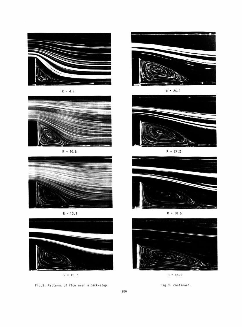
F ig .9. Patterns of flow over a back-step. F ig .9. continued.
286
the measured position of its center are shown in F ig .11
and F ig .12, respectively, being compared with the
calculation. I t is seen that the experimental results
show a good agreement with the calculated results.
1.0
2 B
0.5
O <£o OOC3*CED #o •
O EXPERIMENT• CALCULATION
BY KAWAGUTI
10 50 Rj 100
F ig .10. Position of separation point in a flow
over a step.
F ig .11. Length of standing vortex.
o ____________ 1 V l.-----------------------T
ReG 48
781 106
Jk 1 131e 167
242272
A < t * 307
o « 366• 455▲ CALCULATION
--------------------------------_J_______
BY KAWAGUTI
i
F ig .12. Position of center of standing vortex.
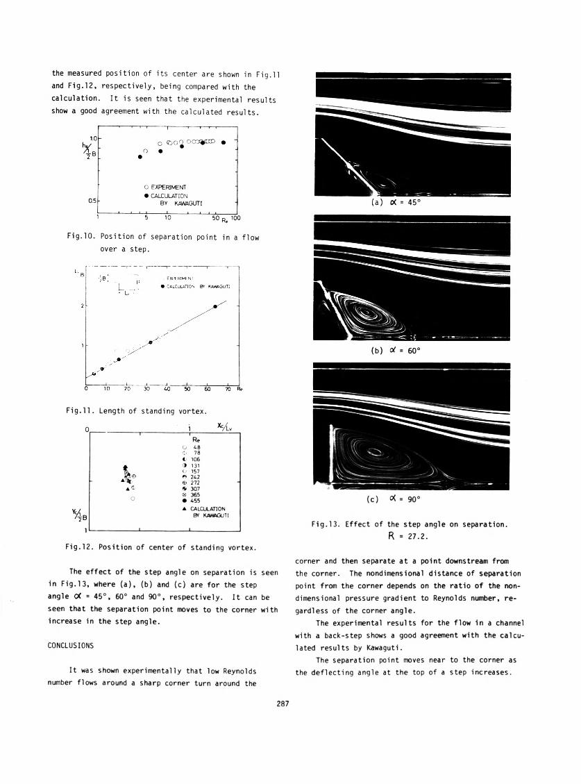
The effect of the step angle on separation is seen
in F ig .13, where (a), (b) and (c) are for the step
angle (X = 45°, 60° and 90°, respectively. I t can be
seen that the separation point moves to the corner with
increase in the step angle.
CONCLUSIONS
(a) 0( = 45°
(b) = 60°
(c) = 90°
F ig .13. Effect of the step angle on separation.
R = 27.2.
corner and then separate at a point downstream from
the corner. The nondimensional distance of separation
point from the corner depends on the ratio of the non-
dimensional pressure gradient to Reynolds number, re
gardless of the corner angle.
The experimental resu lts for the flow in a channel
with a back-step shows a good agreement with the calcu
lated results by Kawaguti.
The separation point moves near to the corner as
the deflecting angle at the top of a step increases.It was shown experimentally that low Reynolds
number flows around a sharp corner turn around the
287
BIBLIOGRAPHY
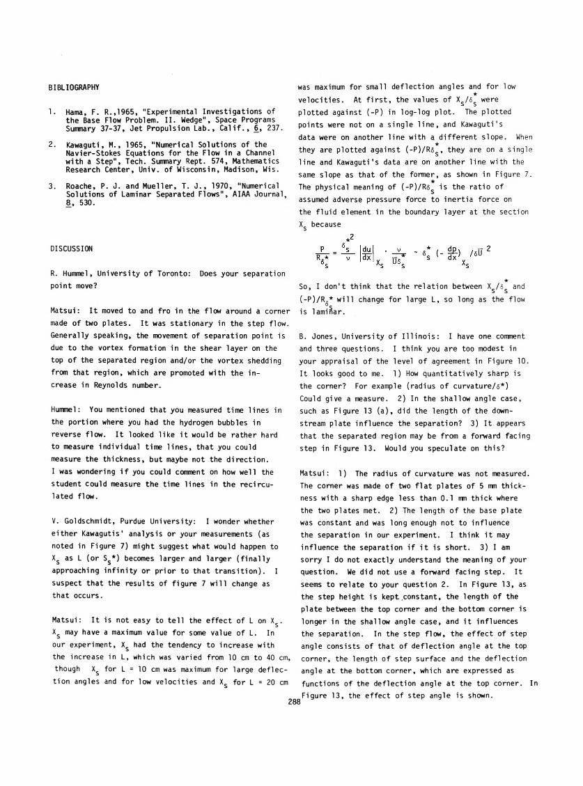
1. Hama, F. R.,1965, "Experimental Investigations of the Base Flow Problem. I I . Wedge", Space Programs Summary 37-37, Jet Propulsion Lab., C a l i f . , 6, 237.
2. Kawaguti, M., 1965, "Numerical Solutions of the Navier-Stokes Equations for the Flow in a Channel with a Step", Tech. Summary Rept. 574, Mathematics Research Center, Univ. of Wisconsin, Madison, Wis.
3. Roache, P. J. and Mueller, T. J ., 1970, "Numerical Solutions of Laminar Separated Flows", AIAA Journal, 8, 530.
DISCUSSION
R. Hummel, University o f Toronto: Does your separation
point move?
Matsui: I t moved to and fro in the flow around a corner
made of two plates. I t was stationary in the step flow.
Generally speaking, the movement of separation point is
due to the vortex formation in the shear layer on the
top of the separated region and/or the vortex shedding
from that region, which are promoted with the in
crease in Reynolds number.
Hummel: You mentioned that you measured time lines in
the portion where you had the hydrogen bubbles in
reverse flow. I t looked like i t would be rather hard
to measure individual time line s, that you could
measure the thickness, but maybe not the direction.
I was wondering i f you could comment on how well the
student could measure the time lines in the recircu
lated flow.
V. Goldschmidt, Purdue University: I wonder whether
either Kawagutis* analysis or your measurements (as
noted in Figure 7) might suggest what would happen to
X$ as L (or Ss*) becomes larger and larger ( f in a l ly
approaching in f in ity or prior to that tran s it io n ). I
suspect that the resu lts of figure 7 w ill change as
that occurs.
Matsui: I t is not easy to te l l the e ffect of L on Xs .
X$ may have a maximum value for some value of L. In
our experiment, X$ had the tendency to increase with
the increase in L, which was varied from 10 cm to 40 cm,
though X$ for L = 10 cm was maximum for large deflec
tion angles and for low ve locities and X$ for L = 20 cm
was maximum for small deflection angles and for low★
ve loc itie s. At f i r s t , the values of Xs /6s were
plotted against (-P) in log-log plot. The plotted
points were not on a sing le lin e , and Kawaguti1s
data were on another line with a d ifferent slope. When
they are plotted against (-P )/R ss , they are on a single
line and Kawaguti's data are on another line with the
same slope as that of the former, as shown in Figure 7.
The physical meaning of ( -P)/R6 is the ratio of
assumed adverse pressure force to inertia force on
the flu id element in the boundary layer at the section
X$ because
So, I don't think that the re lation between Xs /6$ and
(-P )/R {* w ill change for large L, so long as the flow
is laminar.
B. Jones, University o f I l l in o is : I have one comment
and three questions. I think you are too modest in
your appraisal o f the level o f agreement in Figure 10.
I t looks good to me. 1) How quantita tive ly sharp is
the corner? For example (radius o f curvature/6*)
Could give a measure. 2) In the shallow angle case,
such as Figure 13 (a), did the length of the down
stream plate influence the separation? 3) I t appears
that the separated region may be from a forward facing
step in Figure 13. Would you speculate on th is?
Matsui: 1) The radius of curvature was not measured.
The corner was made of two f la t plates of 5 mm thick
ness with a sharp edge less than 0.1 nm thick where
the two plates met. 2) The length o f the base plate
was constant and was long enough not to influence
the separation in our experiment. I think i t may
influence the separation i f i t is short. 3) I am
sorry I do not exactly understand the meaning o f your
question. We did not use a forward facing step. I t
seems to relate to your question 2. In Figure 13, as
the step height is kept constant, the length of the
plate between the top corner and the bottom corner is
longer in the shallow angle case, and i t influences
the separation. In the step flow, the e ffect of step
angle consists o f that of deflection angle at the top
corner, the length of step surface and the deflection
angle at the bottom corner, which are expressed as
functions of the deflection angle at the top corner. I
Figure 13, the effect of step angle is shown.


![Wall-Layer Eruptions in Turbulent Flows - NASA · of large Reynolds numbers. ... wil] provoke eruptions and regenerative interactions ... Wall-Layer Eruptions in Turbulent Flows](https://img.pdfslide.net/doc/110x75/5b7880707f8b9a331e8bc429/wall-layer-eruptions-in-turbulent-flows-nasa-of-large-reynolds-numbers-.jpg)