Embed Size (px)
Citation preview
Separation Processes:
CentrifugesChE 4M3
© Kevin Dunn, 2014
http://learnche.mcmaster.ca/4M3
Overall revision number: 303 (September 2014)
1
Copyright, sharing, and attribution notice
This work is licensed under the Creative Commons Attribution-ShareAlike 4.0
International License. To view a copy of this license, please visit
http://creativecommons.org/licenses/by-sa/4.0/
This license allows you:
I to share - copy and redistribute the material in any way
I to adapt - but you must distribute the new result under thesame or similar license to this one
I commercialize - you are allowed to use this work forcommercial purposes
I attribution - but you must attribute the work as follows:I “Portions of this work are the copyright of Kevin Dunn”, orI “This work is the copyright of Kevin Dunn”
(when used without modification)
2
We appreciate:
I if you let us know about any errors in the slides
I any suggestions to improve the notes
All of the above can be done by writing to
or anonymous messages can be sent to Kevin Dunn at
http://learnche.mcmaster.ca/feedback-questions
If reporting errors/updates, please quote the current revision number: 303
3
References
I Geankoplis, “Transport Processes and Separation ProcessPrinciples”, 3rd or 4th edition, chapter 14.
I Richardson and Harker, “Chemical Engineering, Volume 2”,5th edition, chapter 9.
I Perry’s Chemical Engineers’ Handbook, 8th edition, chapter18.8.
I Svarovsky, “Solid Liquid Separation”, 3rd or 4th edition.
I Seader et al. “Separation Process Principles”, page 800 to802 in 3rd edition.
I Schweitzer, “Handbook of Separation Techniques forChemical Engineers”, chapter 4.5.
4
Why consider centrifuges?
I When gravity (freely available) is not fast enough
I Decrease the separation time and increase separation factor
I Much smaller piece of equipmentI Achieve separations not possible by gravity:
I overcome Brownian limitsI overcome convection currentsI overcome stabilizing forces that hold an emulsion together
Why not just apply flocculation?
5
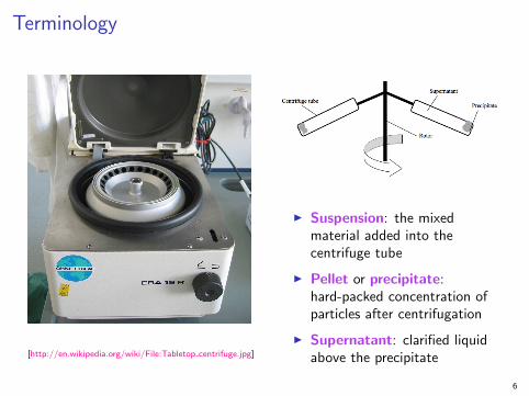
Terminology
[http://en.wikipedia.org/wiki/File:Tabletop centrifuge.jpg]
I Suspension: the mixedmaterial added into thecentrifuge tube
I Pellet or precipitate:hard-packed concentration ofparticles after centrifugation
I Supernatant: clarified liquidabove the precipitate
6
Uses
Used since 1700’s:
1. separate particles from fluid based on density
2. separates immiscible fluids (liquid and even gases) of differentdensities
3. to enhance drainage of fluid from particles for drying
4. enhance mass transfer (look at centrifugal packed bed contactors in your
own time)
Examples:
I Cream from milk (milk is an emulsion)
I Clarification: juice, beer (yeast removal), essential oils
I Widely used in bioseparations: blood, viruses, proteins
I Remove sand and water from heavy oils
7
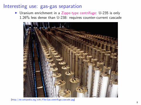
Interesting use: gas-gas separationI Uranium enrichment in a Zippe-type centrifuge: U-235 is only
1.26% less dense than U-238: requires counter-current cascade
[http://en.wikipedia.org/wiki/File:Gas centrifuge cascade.jpg]8
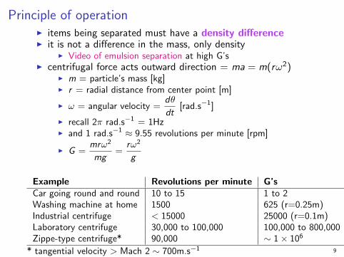
Principle of operationI items being separated must have a density differenceI it is not a difference in the mass, only density
I Video of emulsion separation at high G’sI centrifugal force acts outward direction = ma = m(rω2)
I m = particle’s mass [kg]I r = radial distance from center point [m]
I ω = angular velocity =dθ
dt[rad.s−1]
I recall 2π rad.s−1 = 1HzI and 1 rad.s−1 ≈ 9.55 revolutions per minute [rpm]
I G =mrω2
mg=
rω2
g
Example Revolutions per minute G’sCar going round and round 10 to 15 1 to 2Washing machine at home 1500 625 (r=0.25m)Industrial centrifuge < 15000 25000 (r=0.1m)Laboratory centrifuge 30,000 to 100,000 100,000 to 800,000Zippe-type centrifuge* 90,000 ∼ 1× 10⁶
* tangential velocity > Mach 2 ∼ 700m.s−1 9
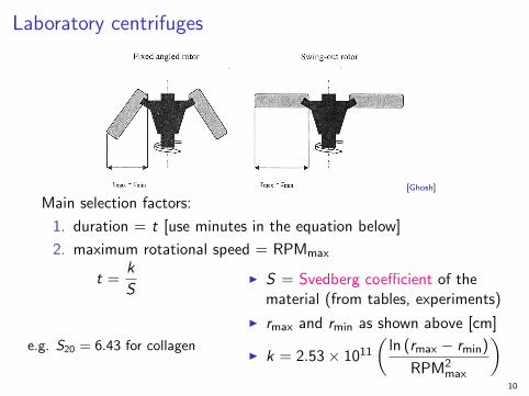
Laboratory centrifuges
[Ghosh]
Main selection factors:
1. duration = t [use minutes in the equation below]
2. maximum rotational speed = RPMmax
t =k
S
e.g. S20 = 6.43 for collagen
I S = Svedberg coefficient of thematerial (from tables, experiments)
I rmax and rmin as shown above [cm]
I k = 2.53× 10¹¹
(ln (rmax − rmin)
RPM2max
)10
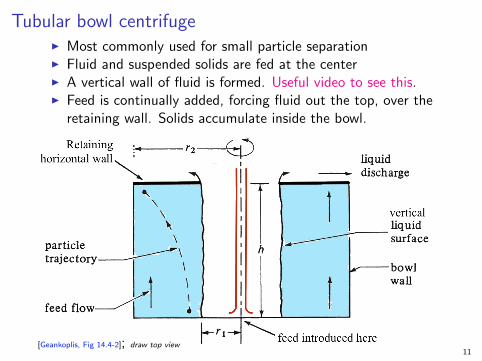
Tubular bowl centrifugeI Most commonly used for small particle separationI Fluid and suspended solids are fed at the centerI A vertical wall of fluid is formed. Useful video to see this.I Feed is continually added, forcing fluid out the top, over the
retaining wall. Solids accumulate inside the bowl.
[Geankoplis, Fig 14.4-2]; draw top view11
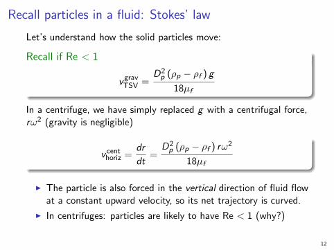
Recall particles in a fluid: Stokes’ law
Let’s understand how the solid particles move:
Recall if Re < 1
vgravTSV =
D2p (ρp − ρf ) g
18µf
In a centrifuge, we have simply replaced g with a centrifugal force,rω2 (gravity is negligible)
v centhoriz =
dr
dt=
D2p (ρp − ρf ) rω2
18µf
I The particle is also forced in the vertical direction of fluid flowat a constant upward velocity, so its net trajectory is curved.
I In centrifuges: particles are likely to have Re < 1 (why?)
12
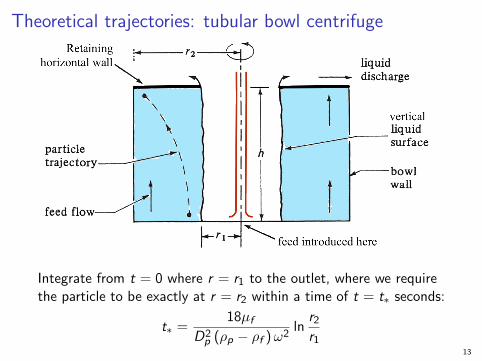
Theoretical trajectories: tubular bowl centrifuge
Integrate from t = 0 where r = r1 to the outlet, where we requirethe particle to be exactly at r = r2 within a time of t = t∗ seconds:
t∗ =18µf
D2p (ρp − ρf )ω2
lnr2r1
13
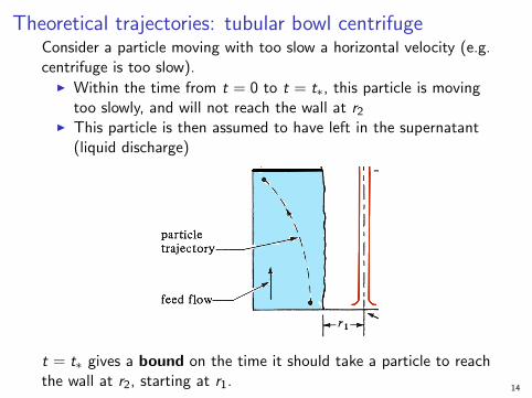
Theoretical trajectories: tubular bowl centrifugeConsider a particle moving with too slow a horizontal velocity (e.g.centrifuge is too slow).
I Within the time from t = 0 to t = t∗, this particle is movingtoo slowly, and will not reach the wall at r2
I This particle is then assumed to have left in the supernatant(liquid discharge)
t = t∗ gives a bound on the time it should take a particle to reachthe wall at r2, starting at r1.
14
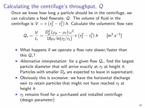
Calculating the centrifuge’s throughput, QOnce we know how long a particle should be in the centrifuge, wecan calculate a feed flowrate, Q. The volume of fluid in thecentrifuge is V = π
(r22 − r2
1
)h. Calculate the volumetric flow rate
Q∗ =V
t∗=
D2p (ρp − ρf )ω2
18µf ln(r2/r1)π(r22 − r2
1
)h [m3.s−1]
I What happens if we operate a flow rate slower/faster thanthis Q∗?
I Alternative interpretation: for a given flow Q∗, find the largestparticle diameter that will arrive exactly at r2 at height h.Particles with smaller Dp are expected to leave in supernatant.
I Obviously this is excessive: we have the horizontal dischargeweir to retain particles that might not have reached r2 atheight h
I r2 remains fixed for a purchased and installed centrifuge(design parameter)
15
Cut-size diameterSo to prevent excessive over design, we rather find the halfwaymark between r1 and r2, and solve the same equations to find thetime, called tcut, for a particle to reach this cut point:
Qcut =V
tcut=
D2p,cut (ρp − ρf )ω2
18µf ln [2r2/(r1 + r2)]π(r22 − r2
1
)h
I we design for the cut-point volumetric flow rate Qcut
I and can then solve for the cut point diameter, Dp,cut
I all other terms in the equation are known/set
I We can also design for a given diameter, and solve for theQcut.
Note: We could use any reasonable point between r1 and r2. The 50%
point is convention. It accounts for uncertainties in our flows, physical
properties and idealities assumed with Stokes’ law.
16
ExampleA lab scale tubular bowl centrifuge has the followingcharacteristics:
I r1 = 16.5 mm and r2 = 22.2 mmI bowl height of 115 mmI 800 revolutions per minute
It is being used to separate bacteria from a fermentation brothexperiment.If the broth has the following properties:
I ρf = 1010 kg.m−3 ← note how close these areI ρp = 1040 kg.m−3
I µf = 0.001 kg.m−1.s−1
I Dp,min = 0.7 µm ← note how small
1. How many G’s is the particle experiencing at r2?2. Calculate both Q∗ and the more realistic Qcut.3. Verify whether Stokes’ law applies.4. What would be the area of the sedimentation vessel that
would operate at this Qcut? Hint: recall that A =Q
vTSV.
17
Example1. Illustrate the trajectory taken by a particle reaching the
cut-point within time tcut
2. In the same duration of time, what trajectory will a smallerparticle have taken?
18
Sigma theory for centrifuges
Take the previous equation for Qcut, multiply numerator anddenominator by g , then substitute Stokes’ law for particles settlingunder gravity:
vgravTSV =
(ρp − ρf ) gD2p
18µf
we obtain:
Qcut =
((ρp − ρf ) gD2
p,cut
18µf
)· (Σ) = vgrav
TSV · Σ
Σ =ω2[πh(r22 − r2
1
)]g ln [2r2/(r1 + r2)]
Σ = f (r1, r2, h, ω)
19
Why use the Sigma term?I Σ = f (r1, r2, h, ω)I it is only a function of the centrifuge’s characteristics; not the
particle or fluidI Σ has units of m2: Σ is the equivalent surface area required
for sedimentation by gravityI Centrifuge A: Qcut,A = vgrav
TSV · ΣA
I Centrifuge B: Qcut,B = vgravTSV · ΣB
IQcut,A
Qcut,B=
ΣA
ΣB
I Used for scale-up of the same feed, i.e. the same vgravTSV
I Used for scale-up within the same types of equipmentI Σ equation is different for other centrifuge typesI Question: if I know ΣA for a given centrifuge and for a given
feed; can I calculate the performance, Qcut,B , for a differentfeed stream?
20
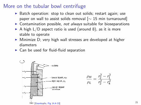
More on the tubular bowl centrifugeI Batch operation: stop to clean out solids; restart again; use
paper on wall to assist solids removal [∼ 15 min turnaround]I Contamination possible, not always suitable for bioseparationsI A high L/D aspect ratio is used (around 8), as it is more
stable to operateI Minimize D; very high wall stresses are developed at higher
diametersI Can be used for fluid-fluid separation
[Geankoplis, Fig 14.4-33]
ρHρL
=r22 − r2
1
r22 − r2
4
21
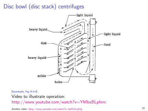
Disc bowl (disc stack) centrifuges
[Geankoplis, Fig 14.4-4]
Video to illustrate operation:http://www.youtube.com/watch?v=YMbaBLpInrc
Another video: http://www.youtube.com/watch?v=bzXUiLajVlg 22
Disc bowl centrifuges
I Recall: Q = V /t∗ (the t∗ will be different for disc bowlcompared to tubular bowl)
I If we increase rate of fluid feed, we get higher throughput, Q
I Adding angled discs gives a greater surface area, hencegreater volume treated, without increasing bowl diameter
I Widely used in bioseparations: no contamination (aseptic)
I Also for: fish oil, fruit juice, beverage clarification
I 3-phases separation: e.g. sand, oil, water mixtures
23
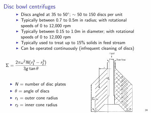
Disc bowl centrifugesI Discs angled at 35 to 50◦; ∼ 50 to 150 discs per unitI Typically between 0.7 to 0.5m in radius; with rotational
speeds of 0 to 12,000 rpmI Typically between 0.15 to 1.0m in diameter; with rotational
speeds of 0 to 12,000 rpmI Typically used to treat up to 15% solids in feed streamI Can be operated continuously (infrequent cleaning of discs)
Σ =2πω2N(r3
1 − r32 )
3g tan θ
I N = number of disc plates
I θ = angle of discs
I r1 = outer cone radius
I r2 = inner cone radius24
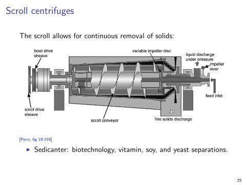
Scroll centrifuges
The scroll allows for continuous removal of solids:
[Perry, fig 18-159]
I Sedicanter: biotechnology, vitamin, soy, and yeast separations.
25
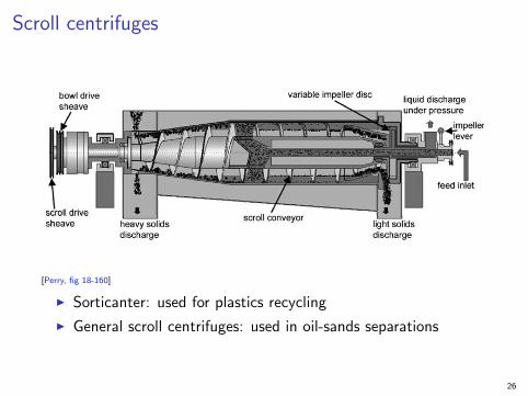
Scroll centrifuges
[Perry, fig 18-160]
I Sorticanter: used for plastics recycling
I General scroll centrifuges: used in oil-sands separations
26
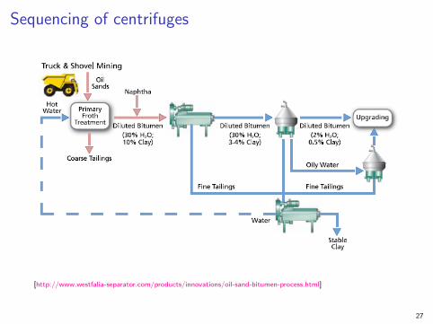
Sequencing of centrifuges
[http://www.westfalia-separator.com/products/innovations/oil-sand-bitumen-process.html]
27
Safety
I careful selection of materials of construction: corrosion andwithstand high forces
I heat removal might be required (some units come withintegrated refrigeration)
I rotational equipment requires careful balanceI digital control is critical
I PLC: programmable logical controllersI SCADA: supervisory control and data acquisitionI safety interlocksI cameras are increasingly used to monitor sediment buildup:
auto-stop and clean
I flammable fluids (e.g. solvents): nitrogen blanket
28
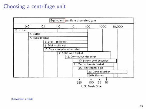
Choosing a centrifuge unit
[Schweitzer, p 4-58]
29
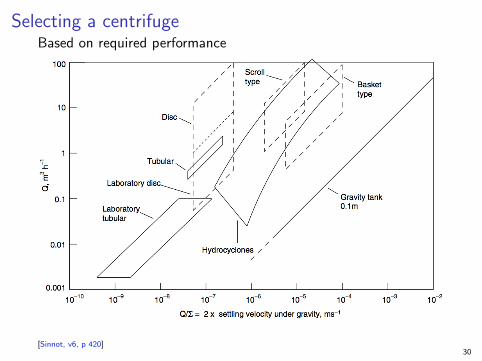
Selecting a centrifugeBased on required performance
[Sinnot, v6, p 420]30
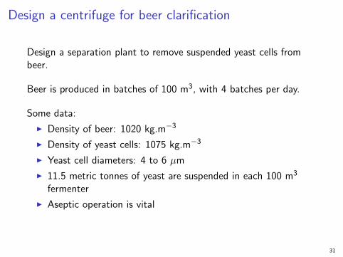
Design a centrifuge for beer clarification
Design a separation plant to remove suspended yeast cells frombeer.
Beer is produced in batches of 100 m3, with 4 batches per day.
Some data:
I Density of beer: 1020 kg.m−3
I Density of yeast cells: 1075 kg.m−3
I Yeast cell diameters: 4 to 6 µm
I 11.5 metric tonnes of yeast are suspended in each 100 m3
fermenter
I Aseptic operation is vital
31
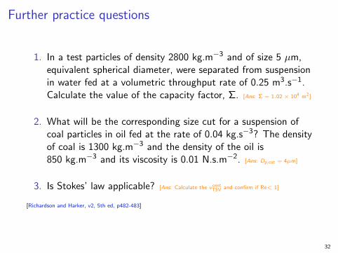
Further practice questions
1. In a test particles of density 2800 kg.m−3 and of size 5 µm,equivalent spherical diameter, were separated from suspensionin water fed at a volumetric throughput rate of 0.25 m3.s−1.Calculate the value of the capacity factor, Σ. [Ans: Σ = 1.02 × 10⁴ m2]
2. What will be the corresponding size cut for a suspension ofcoal particles in oil fed at the rate of 0.04 kg.s−3? The densityof coal is 1300 kg.m−3 and the density of the oil is850 kg.m−3 and its viscosity is 0.01 N.s.m−2. [Ans: Dp,cut = 4µm]
3. Is Stokes’ law applicable? [Ans: Calculate the vcentTSV and confirm if Re< 1]
[Richardson and Harker, v2, 5th ed, p482-483]
32