Embed Size (px)
Citation preview
September 16, 1968
New Products Subassemblies
IC operation keyed to Hall effect Solid state keyboard for computer input terminals tagged at $100
is half the price of comparable electromechanical units
A magnet-actuated integrated circuit is the heart of a solid state keyboard developed by the Micro Switch division of Honeywell Inc.
"To the best of our knowledge, this is the first time that mechanical control of an IC has been accomplished economically in the industry," says James S. Locke, division general manager and a Honeywell vice president.
Locke emphasizes economi-cally." The basic price of the new keyboard is about $100, approximately half that of most electromechanical types. Honeywell hopes to carve out a sizable share of the mushrooming market projected for remote terminals and desk-top computers in the 1970's. The company has started making the keyboards, and is gearing up for full production starting early in 1969.
Each key on the board has its own IC chip. When a key is depressed, a magnet is lowered around the chip and the circuit is actuated. The only mechanical portions are the key itself and its associated spring mechanism.
The IC was the brainchild of Everett A. Vorthmann of the division's advanced engineering department and Joseph Maupin of Honeywell's Solid State Electronics Center in Minneapolis. The circuit includes a Hall generator, a trigger and an amplifier.
Surrounded by field. The circuit's operation depends on the Hall effect-the development of a
Electronics J September 16, 1968
voltage between the two edges of a current-carrying metal strip whose faces are perpendicular to a magnetic field. As the key is depressed, the magnetic field surrounds a metallic epitaxial layer on a chip of p-type silicon, which carries a current perpendicular to the field. The Hall voltage is developed in a direction perpendicular to both the current and the field. It is very small-in microvolts; it is amplified, and the amplifier output flips the trigger, which switches the amplifier's output to the proper lines to represent the binary code for the depressed key.
Four bonded wires connect the terminal of the chip to a lead frame, which is fastened to a single-side, glass epoxy printedcircuit terminal board. A comb, soldered just above the top switch row, provides the jumpers or connections for all of the negative inputs in each column of switches. A second p-c iboard, for the encoding, is mounted below the terminal board and is two-sided.
One side of the encoding board has two vertical columns of conductors for each key, and the reverse side is made up of 32 horizontal rows of conductors. These, in effect, are two separate grid systems. With 16 possible combinations of a four-bit binary code -four O's through four l's-and each system utilizing a four-bit code, two grid outputs can be combined to yield an eight-bit code.
The net result: a specific eight-bit code for each key.
Because the keyboard was designed to meet the American Standard Code for Information Interchange (ASCII) requirements, two separate codes, one each for the shifted and unshifted modes, are assigned to each key. The codes differ by only a single bit so that
Button action. Lead frame with four terminals, at bottom, has IC mounted near top edge. Just above it is plunger with magnet which surrounds chip and actuates circuit. At top are key button and, under it, the switch housing.
169
iMAGIN E! A current regulator that makes no compromise with the voltage mode!
Kepco's new CC line, six models from 0-200 mA to 0-2 amperes, with load ratings of b-lOOV to 0-7V, all made in a 1/6th rack plugin configuration.
Typical CC Module showing the slide and plug-in provisions that make it so flexible.
Special linear IC's control the regulator (0.01 O/o) and isolate the dual metering circuit (no loading). The ammeter and the 10-turn current control are switched over a 10 :1 range for enhanced set-and-read resolution at the low end.
Recovery is at an amazing 2 µ.sec per volt (except 4 µ.sec/V for the 2A-7V model) made possible by a special capacitorless output filter (no unwanted stored energy) that yields a modest 0.020/o ripple and noise figure:
MODEL VOLTS AMPS PRICE
CC 7-2M 0-7 0-2 195.00 CC 15- 1.5M 0-15 0-1.5 195.00 CC 21-1M 0-21 0-1 195.00 CC 40-0.5M 0-40 0-0.5 195.00 CC 72-0.3M 0-72 0-0.3 195.00 CC 10~.2M 0-100 0-0.2 195.00
The Kepco CC current sources are FAST, ACCURATE and SMALL. Mount l, 2, 3 or 6 of them in available housings.
For full story write Dept. AL-14
(-;c_-;;-,;-c;c;:;. -------------- ®
131·38 SANFORD AVE.• FLUSHING. N.Y. 11352 (212) 461-7000 •TWX # 710-582-2631
170 Circle 170 on reader service card
... solid state design eliminates need
for special circuits to combat bounce ...
shift-such as between upper and lower case-can be accomplished by the inversion of the single bit. Besides ASCII, however, the keyboards can also be coded in extended binary coded decimal interchange code (EBCDIC) often used in IBM equipment.
Switch to DTL. Despite the mounting interest by computer makers in transistor-transistor logic for their newer machines, Micro Switch has chosen to go with diode-transistor logic. "We started out with resistor-transistor logic,"
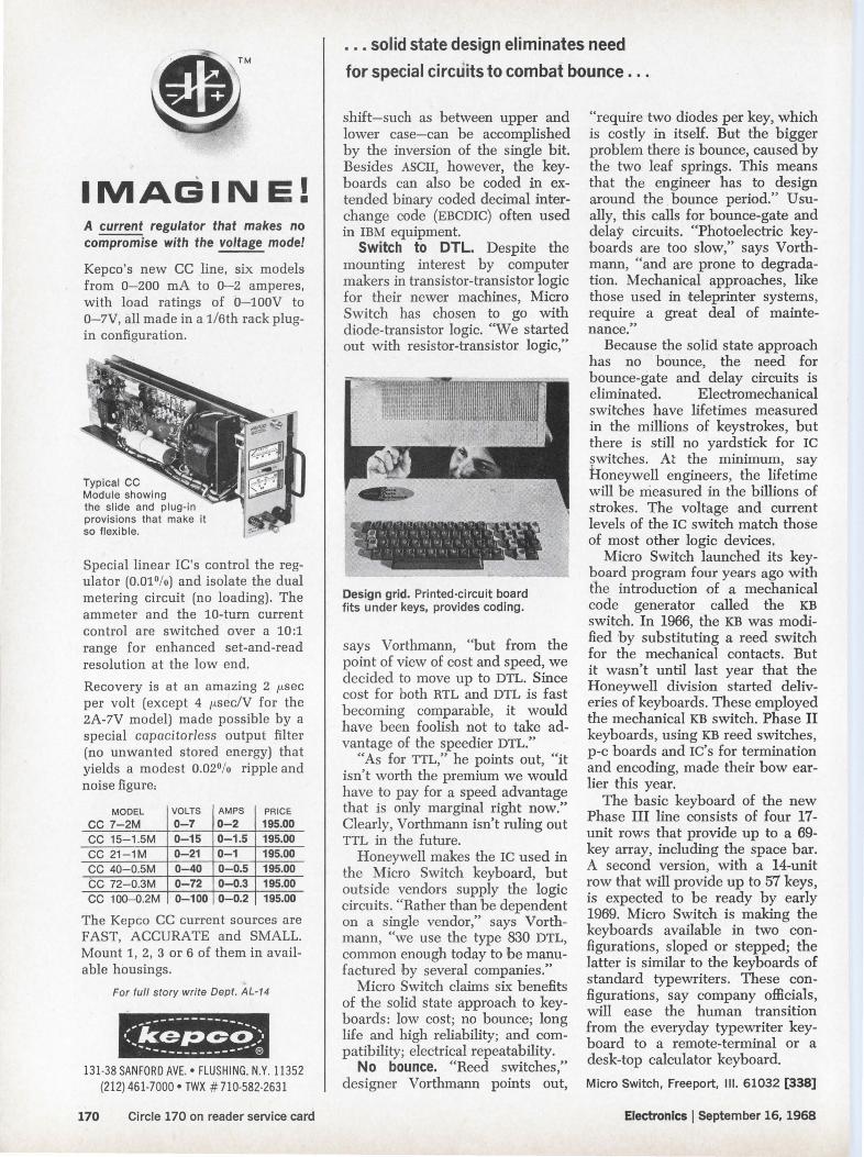
Design grid. Printed-circuit board fits under keys, provides coding.
says Vorthmann, "but from the point of view of cost and speed, we decided to move up to DTL. Since cost for both RTL and DTL is fast becoming comparable, it would have been foolish not to take advantage of the speedier DTL."
"As for TTL," he points out, "it isn't worth the premium we would have to pay for a speed advantage that is only marginal right now." Clearly, Vorthmann isn't ruling out TTL in the future.
Honeywell makes the IC used in the Micro Switch keyboard, but outside vendors supply the logic circuits. "Rather than be dependent on a single vendor," says Vorthmann, "we use the type 830 DTL, common enough today to the manufactured by several companies."
Micro Switch claims six benefits of the solid state approach to keyboards: low cost; no bounce; long life and high reliability; and compatibility; electrical repeatability.
No bounce. "Reed switches," designer Vorthmann points out,
" require two diodes per key, which is costly in itself. But the bigger problem there is bounce, caused by the two leaf springs. This means that the engineer has to design around the bounce period." Usually, this calls for bounce-gate and dela)" circuits. "Photoelectric keyboards are too slow," says Vorthmann, "and are prone to degradation. Mechanical approaches, like those used in teleprinter systems, require a great deal of maintenance."
Because the solid state approach has no bounce, the need for bounce-gate and delay circuits is eliminated. Electromechanical switches have lifetimes measured in the millions of keystrokes, but there is still no yardstick for IC ~witches. At the minimum, say Honeywell engineers, the lifetime will be measured in the billions of strokes. The voltage and current levels of the IC switch match those of most other logic devices.
Micro Switch launched its keyboard program four years ago with the introduction of a mechanical code generator called the KB switch. In 1966, the KB was modified ·by substituting a reed switch for the mechanical contacts. But it wasn't until last year that the Honeywell division started deliveries of keyboards. These employed the mechanical KB switch. Phase II keyboards, using KB reed switches, p-c boards and IC' s for termination and encoding, made their bow earlier this year.
The basic keyboard of the new Phase III line consists of four 17-unit rows that provide up to a 69-key array, including the space bar. A second version, with a 14-unit row that will provide up to 57 keys, is expected to be ready by early 1969. Micro Switch is making the keyboards available in two configurations, sloped or stepped; the latter is similar to the keyboards of standard typewriters. These configurations , say company officials, will ease the human transition from the everyday typewriter keyboard to a remote-terminal or a desk-top calculator keyboard.
Micro Switch, Freeport, Ill. 61032 [338]
Electrohics I September 16, 1968