Embed Size (px)
Citation preview

PRODUCT MANUALDesigned, Manufactured and Supported in the USA
C O M M U N I C AT I O N & S E C U R I T Y S O L U T I O N S
VoIP Entry Phones
Features
The E-10/20/30-IP VoIP Entry Phones are designed to
provide quick and reliable handsfree communication for
SIP VoIP phone systems with PoE. The E-10/20/30-IP
entry phones can be programmed from any Touch Tone
phone or PC on the same LAN. The Entry phones can
dial up to 5 programmable numbers.
The E-10/20/30-IP entry phones will flash the “Call” LED
during dialing and automatically light the LED when the
call is answered. All programming parameters, including
phone numbers and location numbers, are stored in
non-volatile memory, requiring no batteries. All units are
PoE powered.
For outdoor installations where the unit is exposed to
precipitation or condensation, the E-10/20/30-IP Entry
phones are available with Enhanced Weather Protection
(EWP). EWP products feature foam rubber gaskets and
boots, sealed connections, gel-filled butt connectors, as
well as urethane or thermal plastic potted circuit boards.
For more information, see DOD# 859.
• Self diagnostic reports via email (testing com, mic, speaker & switch)• Automatic polling and programming software included• 2 Amp relay contacts for door/gate or SL-2 strobe light control• Blue “Call Connected” LED indicator (E-10/E-30-IP only)• SIP compatible (see pg 2 for list of compatible IP-PBX phone systems)• PoE powered (class 1, <4 watts)• Automatic Noise Canceling (ANC) feature for proper operation
in noisy environments• Network downloadable firmware• Handsfree operation• Marine grade 316 stainless steel prevents corrosion on the stain-
less steel models• Programmable to dial up to 5 numbers on busy or ring no answer• Cycles through backup phone numbers on busy or no-answer• Optional Enhanced Weather Protection (EWP), EWP products are
designed to meet IP66 Ingress Protection Rating, see DOD# 859• Hangs up on busy signal, time-out or touch tone command• Remotely programmable • Extended temperature range (-15°F to 130°F)• 3 different chassis or board only available • Volume adjustments for microphone and speaker• E-10-IP and E-30-IP are flush mountable using the included rough-
in box or can be surface mounted using an optional VE-5x5 Sur-face Mount Box (DOD# 424)
• Optional PB-100 Polling System available (DOD# 232)• Optional SL-2 or BLK-4-EWP strobe light kit available (DOD#
242/653)
• Gate Entrance
• Parking ramps/lots
• ATM machines
• Medical centers
• Lobbies
Power: PoE class 1 (<4 watts)
Dimensions: See Installation and Specifications
Operating Temperature: -26° C to 54° C (-15°F to 130°F)
Humidity - Standard Products: 5% to 95% non-con-
densing
Humidity - EWP Products: Up to 100%
Audio Codecs: G711u, G711a, G722
Connections: (1) RJ45 10/100 Base-T, (3) gel-filled butt
connectors
E-10/20/30-IPVoIP Entry Phones
September 8, 2014
Applications
Specifications
www.vikingelectronics.comInformation: (715) 386-8861
VIKING
• Entryways
• Stadiums
• Convention centers
• Public access areas
Beta Units Available3rd Quarter 2014
E-10-IP/E-10-IP-EWPFlush Mount Black
Powder Painted Aluminum
E-20-IP/E-20-IP-EWPSurface Mount Light GreyUV Stable Plastic Chassis
E-30-IP/E-30-IP-EWPFlush Mount Brushed 316
Stainless Steel
E-30-IP/E-30-IP-EWPShown in Optional VE-5x5
Surface Mount Box
2
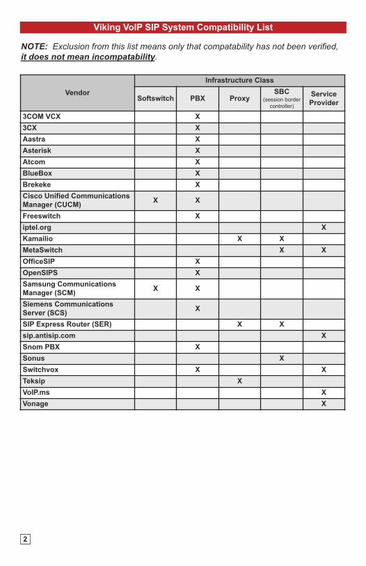
Viking VoIP SIP System Compatibility List
Vendor
Infrastructure Class
Softswitch PBX ProxySBC
(session border
controller)
Service
Provider
3COM VCX X
3CX X
Aastra X
Asterisk X
Atcom X
BlueBox X
Brekeke X
Cisco Unified Communications
Manager (CUCM)X X
Freeswitch X
iptel.org X
Kamailio X X
MetaSwitch X X
OfficeSIP X
OpenSIPS X
Samsung Communications
Manager (SCM)X X
Siemens Communications
Server (SCS)X
SIP Express Router (SER) X X
sip.antisip.com X
Snom PBX X
Sonus X
Switchvox X X
Teksip X
VoIP.ms X
Vonage X
NOTE: Exclusion from this list means only that compatability has not been verified,it does not mean incompatability.
Features Overview
Definitions
Client: A computer or device that makes use of a server. As an example, the client might request a particular file from the server.
DHCP: Dynamic Host Configuration Protocol. In this procedure the network server or router takes note of a client’s MAC address and assigns an
IP address to allow the client to communicate with other devices on the network.
DNS Server: A DNS (Domain Name System) server translates domain names (ie: www.vikingelectronics.com) into an IP address.
Ethernet: Ethernet is the most commonly used LAN technology. An ethernet Local Area Network typically uses twisted pair wires to achieve trans-
mission speeds up to 1Gbps.
Host: A computer or device connected to a network.
Host Name: A host name is a label assigned to a device connected to a computer network that is used to identify the device in various forms of
network communication.
Hosts File: A file stored in a computer that lists host names and their corresponding IP addresses with the purpose of mapping addresses to hosts
or vice versa.
Internet: A worldwide system of computer networks running on IP protocol which can be accessed by individual computers or networks.
IP: Internet Protocol is the set of communications conventions that govern the way computers communicate on networks and on the Internet.
IP Address: This is the address that uniquely identifies a host on a network.
LAN: Local Area Network. A LAN is a network connecting computers and other devices within an office or building.
Lease: The amount of time a DHCP server reserves an address it has assigned. If the address isn’t used by the host for a period of time, the lease
can expire and the address can be assigned to another host.
MAC Address: MAC stands for Media Access Control. A MAC address, also called a hardware address or physical address, is a unique address
assigned to a device at the factory. It resides in the device’s memory and is used by routers to send network traffic to the correct IP address. You
can find the MAC address of your E-10/20/30-IP phone printed on a white label on the top surface of the PoE LAN port.
Router: A device that forwards data from one network to another. In order to send information to the right location, routers look at IP Address, MAC
Address and Subnet Mask.
Server: A computer or device that fulfills requests from a client. This could involve the server sending a particular file requested by the client.
Session Initiation Protocol (SIP): Is a signaling communications protocol, widely used for controlling multimedia communication sessions such
as voice and video calls over Internet Protocol (IP) networks. The protocol defines the messages that are sent between endpoints, which govern
establishment, termination and other essential elements of a call.
Static IP Address: A static IP Address has been assigned manually and is permanent until it is manually removed. It is not subject to the Lease
limitations of a Dynamic IP Address assigned by the DHCP Server.
WAN: Wide Area Network. A WAN is a network comprising a large geographical area like a state or country. The largest WAN is the Internet.
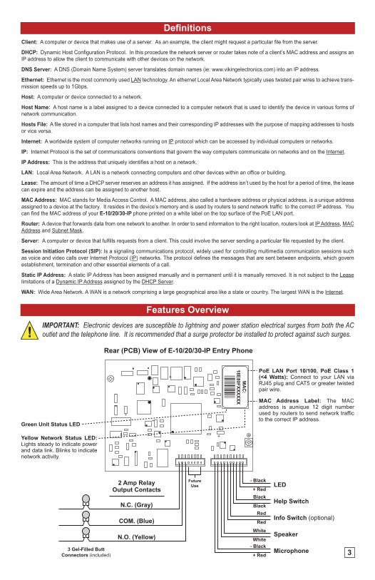
IMPORTANT: Electronic devices are susceptible to lightning and power station electrical surges from both the ACoutlet and the telephone line. It is recommended that a surge protector be installed to protect against such surges.
N.C. (Gray)
N.O. (Yellow)
COM. (Blue)
2 Amp Relay Output Contacts
3 Gel-Filled ButtConnectors (included)
- Black
+ RedBlack
Black
- Black
+ Red
LED
Help Switch
Info Switch (optional)
Speaker
Microphone
MAC Address Label: The MAC address is aunique 12 digit number used by routers to send network traffic to the correct IP address.
PoE LAN Port 10/100, PoE Class 1 (<4 Watts): Connect to your LAN via RJ45 plug and CAT5 or greater twisted pair wire.
Yellow Network Status LED: Lights steady to indicate power and data link. Blinks to indicate network activity.
Green Unit Status LED
Rear (PCB) View of E-10/20/30-IP Entry Phone
Red
Red
White
White
FutureUse
MA
C:
18E80FXXXXXX
asdesaxtff
3
4
Installation
Front View of OptionalVE-5x5 (not included)2.25”
CondensationDrain Hole
* 1/8" thick foamgasket (included)
5.14”
5.22”3.25”
Call
4.0"
Rear View of VE-5x5 (not included)
Push to Call Button
(4) 6-32 X 3/4” stainless steel, flat head, hexdrive, screws (included)
Condensation Drain Hole
5.0”Typical
(4) 0.38” diameter (for gooseneck mounting)
(4) 0.2 x 0.43 slots for double gang box
(2) 0.2 x 0.43 slots for single gang box
(1) .74" dia
3.0” 3.3”
3.0”
2.1”
Wa
ll S
tud
Front View of PlasticRough-In Box (included)
Wire knock out
(2) Standard flat head dry wall (sheet rock) screws (not included)
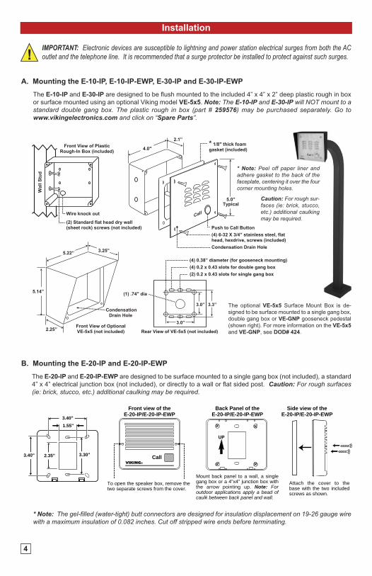
The E-10-IP and E-30-IP are designed to be flush mounted to the included 4” x 4” x 2” deep plastic rough in box
or surface mounted using an optional Viking model VE-5x5. Note: The E-10-IP and E-30-IP will NOT mount to astandard double gang box. The plastic rough in box (part # 259576) may be purchased separately. Go towww.vikingelectronics.com and click on “Spare Parts”.
A. Mounting the E-10-IP, E-10-IP-EWP, E-30-IP and E-30-IP-EWP
The optional VE-5x5 Surface Mount Box is de-
signed to be surface mounted to a single gang box,
double gang box or VE-GNP gooseneck pedestal
(shown right). For more information on the VE-5x5
and VE-GNP, see DOD# 424.
* Note: Peel off paper liner andadhere gasket to the back of thefaceplate, centering it over the fourcorner mounting holes.
The E-20-IP and E-20-IP-EWP are designed to be surface mounted to a single gang box (not included), a standard
4” x 4” electrical junction box (not included), or directly to a wall or flat sided post. Caution: For rough surfaces(ie: brick, stucco, etc.) additional caulking may be required.
B. Mounting the E-20-IP and E-20-IP-EWP
UP
CallVIKING©
3.40"1.55"
3.40" 2.35" 3.30"
Front view of theE-20-IP/E-20-IP-EWP
Back Panel of theE-20-IP/E-20-IP-EWP
Side view of theE-20-IP/E-20-IP-EWP
To open the speaker box, remove the two separate screws from the cover.
Mount back panel to a wall, a single gang box or a 4”x4” junction box with the arrow pointing up. Note: For outdoor applications apply a bead of caulk between back panel and wall.
Attach the cover to the base with the two included screws as shown.
* Note: The gel-filled (water-tight) butt connectors are designed for insulation displacement on 19-26 gauge wirewith a maximum insulation of 0.082 inches. Cut off stripped wire ends before terminating.
Caution: For rough sur-faces (ie: brick, stucco,etc.) additional caulkingmay be required.
IMPORTANT: Electronic devices are susceptible to lightning and power station electrical surges from both the ACoutlet and the telephone line. It is recommended that a surge protector be installed to protect against such surges.
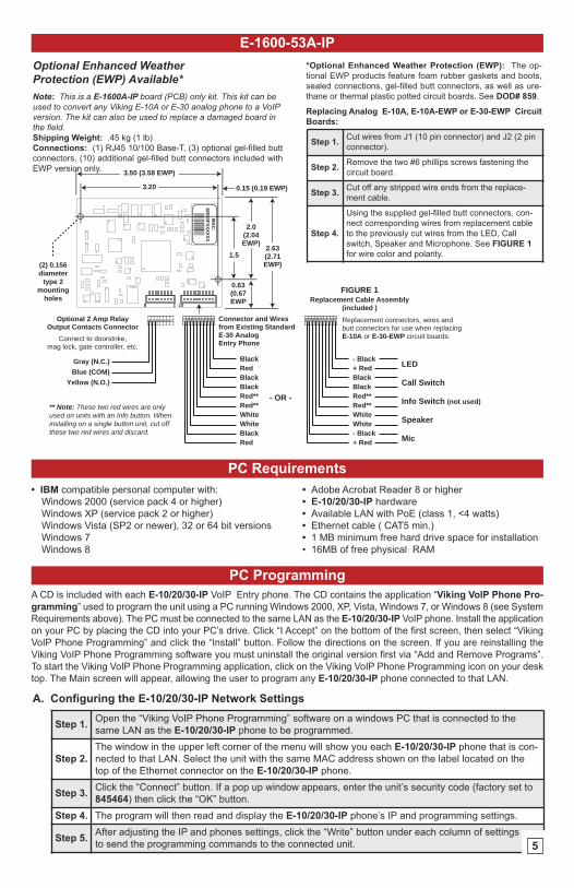
E-1600-53A-IP
(2) 0.156diameter
type 2mounting
holes
0.15 (0.19 EWP)
3.50 (3.58 EWP)
3.20
2.0(2.04EWP)
0.63(0.67EWP
1.52.63(2.71EWP)
Gray (N.C.)Blue (COM)
Yellow (N.O.)
BlackRedBlackBlackRed**Red**WhiteWhiteBlackRed
- Black+ RedBlackBlackRed**Red**WhiteWhite- Black+ Red
LED
Call Switch
Info Switch (not used)
Speaker
Mic
Connector and Wiresfrom Existing StandardE-30 AnalogEntry Phone
FIGURE 1Replacement Cable Assembly
(included )
- OR -
Replacement connectors, wires andbutt connectors for use when replacingE-10A or E-30-EWP circuit boards.
Optional 2 Amp RelayOutput Contacts Connector
Connect to doorstrike,mag lock, gate controller, etc.
** Note: These two red wires are only used on units with an Info button. When installing on a single button unit, cut off these two red wires and discard.
8 1 10 1
MA
C:
18E80FXXXXXX
asdesaxtff
Note: This is a E-1600A-IP board (PCB) only kit. This kit can beused to convert any Viking E-10A or E-30 analog phone to a VoIPversion. The kit can also be used to replace a damaged board inthe field.Shipping Weight: .45 kg (1 lb)
Connections: (1) RJ45 10/100 Base-T, (3) optional gel-filled butt
connectors, (10) additional gel-filled butt connectors included with
EWP version only.
Optional Enhanced WeatherProtection (EWP) Available*
*Optional Enhanced Weather Protection (EWP): The op-
tional EWP products feature foam rubber gaskets and boots,
sealed connections, gel-filled butt connectors, as well as ure-
thane or thermal plastic potted circuit boards. See DOD# 859.
Step 1.Cut wires from J1 (10 pin connector) and J2 (2 pin
connector).
Step 2.Remove the two #6 phillips screws fastening the
circuit board.
Step 3.Cut off any stripped wire ends from the replace-
ment cable.
Step 4.
Using the supplied gel-filled butt connectors, con-
nect corresponding wires from replacement cable
to the previously cut wires from the LED, Call
switch, Speaker and Microphone. See FIGURE 1
for wire color and polarity.
Replacing Analog E-10A, E-10A-EWP or E-30-EWP Circuit
Boards:
PC Requirements
• IBM compatible personal computer with:
Windows 2000 (service pack 4 or higher)
Windows XP (service pack 2 or higher)
Windows Vista (SP2 or newer), 32 or 64 bit versions
Windows 7
Windows 8
PC Programming
A CD is included with each E-10/20/30-IP VoIP Entry phone. The CD contains the application “Viking VoIP Phone Pro-
gramming” used to program the unit using a PC running Windows 2000, XP, Vista, Windows 7, or Windows 8 (see System
Requirements above). The PC must be connected to the same LAN as the E-10/20/30-IP VoIP phone. Install the application
on your PC by placing the CD into your PC’s drive. Click “I Accept” on the bottom of the first screen, then select “Viking
VoIP Phone Programming” and click the “Install” button. Follow the directions on the screen. If you are reinstalling the
Viking VoIP Phone Programming software you must uninstall the original version first via “Add and Remove Programs”.
To start the Viking VoIP Phone Programming application, click on the Viking VoIP Phone Programming icon on your desk
top. The Main screen will appear, allowing the user to program any E-10/20/30-IP phone connected to that LAN.
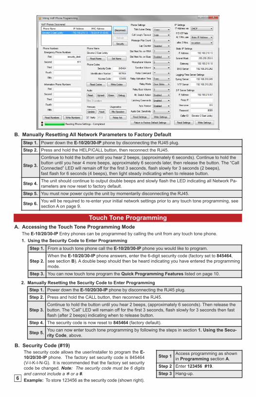
A. Configuring the E-10/20/30-IP Network Settings
Step 1.Open the “Viking VoIP Phone Programming” software on a windows PC that is connected to the
same LAN as the E-10/20/30-IP phone to be programmed.
Step 2.
The window in the upper left corner of the menu will show you each E-10/20/30-IP phone that is con-
nected to that LAN. Select the unit with the same MAC address shown on the label located on the
top of the Ethernet connector on the E-10/20/30-IP phone.
Step 3.Click the “Connect” button. If a pop up window appears, enter the unit’s security code (factory set to
845464) then click the “OK” button.
Step 4. The program will then read and display the E-10/20/30-IP phone’s IP and programming settings.
Step 5.After adjusting the IP and phones settings, click the “Write” button under each column of settings
to send the programming commands to the connected unit.
• Adobe Acrobat Reader 8 or higher
• E-10/20/30-IP hardware
• Available LAN with PoE (class 1, <4 watts)
• Ethernet cable ( CAT5 min.)
• 1 MB minimum free hard drive space for installation
• 16MB of free physical RAM
5
6
A. Accessing the Touch Tone Programming Mode
Touch Tone Programming
1. Using the Security Code to Enter Programming
Step 1. From a touch tone phone call the E-10/20/30-IP phone you would like to program.
Step 2.
When the E-10/20/30-IP phone answers, enter the 6-digit security code (factory set to 845464,
see section B). A double beep should then be heard indicating you have entered the programming
mode.
Step 3. You can now touch tone program the Quick Programming Features listed on page 10.
2. Manually Resetting the Security Code to Enter Programming
Step 1. Power down the E-10/20/30-IP phone by disconnecting the RJ45 plug.
Step 2. Press and hold the CALL button, then reconnect the RJ45.
Step 3.
Continue to hold the button until you hear 2 beeps, (approximately 6 seconds). Then release the
button. The “Call” LED will remain off for the first 3 seconds, flash slowly for 3 seconds then fast
flash (after 2 beeps) indicating when to release button.
Step 4. The security code is now reset to 845464 (factory default).
Step 5.You can now enter touch tone programming by following the steps in section 1. Using the Secu-
rity Code, above.
The E-10/20/30-IP Entry phones can be programmed by calling the unit from any touch tone phone.
Step 1Access programming as shown
in Programming section A.
Step 2 Enter 123456 #19.
Step 3 Hang-up.
B. Security Code (#19)
The security code allows the user/installer to program the E-
10/20/30-IP phone. The factory set security code is 845464
(V-I-K-I-N-G). It is recommended that the factory set security
code be changed. Note: The security code must be 6 digitsand cannot include a Q or a #.Example: To store 123456 as the security code (shown right).
Step 1. Power down the E-10/20/30-IP phone by disconnecting the RJ45 plug.
Step 2. Press and hold the HELP/CALL button, then reconnect the RJ45.
Step 3.
Continue to hold the button until you hear 2 beeps, (approximately 6 seconds). Continue to hold the
button until you hear 4 more beeps, approximately 6 seconds later, then release the button. The “Call
Connected” LED will remain off for the first 3 seconds, flash slowly for 3 seconds (2 beeps),
fast flash for 6 seconds (4 beeps), then light steady indicating when to release button.
Step 4.The unit should continue to output double beeps and slowly flash the LED indicating all Network Pa-
rameters are now reset to factory default.
Step 5. You must now power cycle the unit by momentarily disconnecting the RJ45.
Step 6.You will be required to re-enter your initial network settings prior to any touch tone programming, see
section A on page 9.
B. Manually Resetting All Network Parameters to Factory Default
7
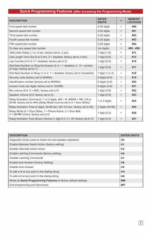
Quick Programming Features (after accessing the Programming Mode)
DESCRIPTIONENTER
DIGITS+
MEMORY
LOCATION
First speed dial number 0-20 digits + #00
Second speed dial number 0-20 digits + #01
Third speed dial number 0-20 digits + #02
Fourth speed dial number 0-20 digits + #03
Fifth speed dial number 0-20 digits + #04
To clear any speed dial number (no digits) + #00 - #09
Talk/Listen Delay (.1 to .9 sec, factory set to .2 sec) 1 digit (1-9) + #11
Call Length Time Out (0 to 9 min, 0 = disabled, factory set to 3 min) 1 digit (0-9) + #12
Lap Counter (0 to 9, 0 = disabled, factory set to 0) 1 digit (0-9) + #16
Dial Next Number on Ring No Answer (0 or 1 = disabled, 2 - 9 = number
of rings, factory set to 7)1 digit (0-9) + #17
Dial Next Number on Busy (1 or 2, 1 = disabled, factory set to 2/enabled) 1 digit (1 or 2) + #18
Security code (factory set to 845464) 6 digits (0-9) + #19
Identification number (factory set to 987654) 6 digits (0-9) + #20
Access Code (six digits, factory set to 123456) 6 digits (0-9) + #21
Mic volume (0-9, 0 = ANC, factory set to 5) 1 digit (0-9) + #22
Speaker Volume (0-9, factory set to 5) 1 digit (0-9) + #23
Relay Activation Command ( 1 or 2 digits, QQ = Q, QQQQ = QQ, 0-9 or
00-99, factory set to QQ) (Relay Mode must be set to 0 = Door Strike)1 or 2 digits + #24
Relay Activation Time (2 digits, 00-99 sec, 00= 0.5 sec, factory set to 05) 2 digits (00-99) + #25
Relay Mode (0 = Door Strike, 1 = Phone Active, 2 = Door Bell,
3 = LV-1K Control, factory set to 0)1 digit (0-3) + #26
Relay Activation Tone (Buzz) Volume (1 digit 0-3, 0 = off, factory set to 3) 1 digit (0-3) + #27
DESCRIPTION ENTER DIGITS
Diagnostic tones (used to check mic and speaker operation) Q0
Enable Alternate Switch Action (factory setting) Q1
Disable Alternate switch Action Q2
Enable Latching Commands (factory setting) Q6
Disable Latching Commands Q7
Enable Auto Answer (Factory Setting) Q8
Disable Auto Answer Q9
To add a Q at any point in the dialing string QQ
To add a # at any point in the dialing string Q#
Reset all Quick Programming Features to factory default settings ###
Exit programming and disconnect ##7
8
To Program the E-10/20/30-IP Phone... Step 1 Step 2
...to store 555-1234 as the first speed dial
number
Enter Programming(see A. Accessing the Touch Tone
Programming Mode, page 10)
Enter digits:
5 5 5 1 2 3 4 # 0 0
...to clear the first speed dial numberEnter Programming
(see A. Accessing the Touch Tone
Programming Mode, page 10)
Enter digits:
# 0 0
1. Speed Dial Numbers (memory locations #00 - #04)
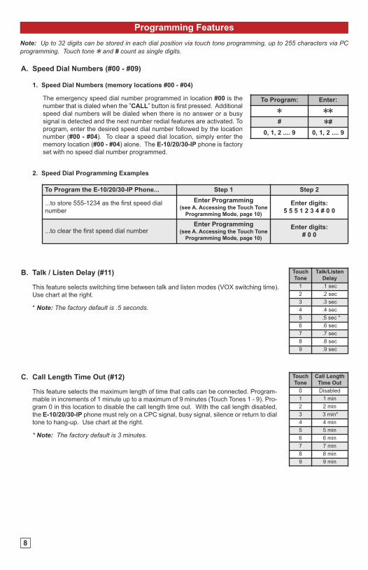
A. Speed Dial Numbers (#00 - #09)
Programming Features
Note: Up to 32 digits can be stored in each dial position via touch tone programming, up to 255 characters via PCprogramming. Touch tone Q and # count as single digits.
The emergency speed dial number programmed in location #00 is the
number that is dialed when the ”CALL” button is first pressed. Additional
speed dial numbers will be dialed when there is no answer or a busy
signal is detected and the next number redial features are activated. To
program, enter the desired speed dial number followed by the location
number (#00 - #04). To clear a speed dial location, simply enter the
memory location (#00 - #04) alone. The E-10/20/30-IP phone is factory
set with no speed dial number programmed.
To Program: Enter:
Q QQ
# Q#
0, 1, 2 .... 9 0, 1, 2 .... 9
2. Speed Dial Programming Examples
This feature selects switching time between talk and listen modes (VOX switching time).
Use chart at the right.
* Note: The factory default is .5 seconds.
B. Talk / Listen Delay (#11)
This feature selects the maximum length of time that calls can be connected. Program-
mable in increments of 1 minute up to a maximum of 9 minutes (Touch Tones 1 - 9). Pro-
gram 0 in this location to disable the call length time out. With the call length disabled,
the E-10/20/30-IP phone must rely on a CPC signal, busy signal, silence or return to dial
tone to hang-up. Use chart at the right.
* Note: The factory default is 3 minutes.
C. Call Length Time Out (#12)
Touch
Tone
Talk/Listen
Delay
1 .1 sec
2 .2 sec
3 .3 sec
4 .4 sec
5 .5 sec *
6 .6 sec
7 .7 sec
8 .8 sec
9 .9 sec
Touch
Tone
Call Length
Time Out
0 Disabled
1 1 min
2 2 min
3 3 min*
4 4 min
5 5 min
6 6 min
7 7 min
8 8 min
9 9 min
Touch
Tone
Ring No
Answer
0 Disabled
1 Disabled
2 2 rings
3 3 rings
4 4 rings
5 5 rings
6 6 rings
7 7 rings*
8 8 rings
9 9 rings
Touch
Tone
Lap
Counter
0 Disabled*
1 1 time
2 2 time
3 3 time
4 4 time
5 5 time
6 6 time
7 7 time
8 8 time
9 9 time
Touch
ToneDial on Busy
1 Disabled
2 Enabled*
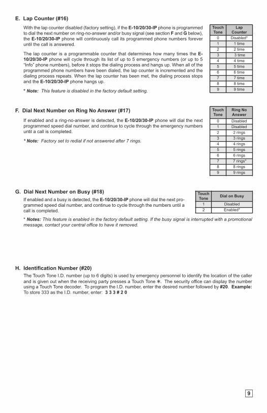
With the lap counter disabled (factory setting), if the E-10/20/30-IP phone is programmed
to dial the next number on ring-no-answer and/or busy signal (see section F and G below),
the E-10/20/30-IP phone will continuously call its programmed phone numbers forever
until the call is answered.
The lap counter is a programmable counter that determines how many times the E-
10/20/30-IP phone will cycle through its list of up to 5 emergency numbers (or up to 5
“Info” phone numbers), before it stops the dialing process and hangs up. When all of the
programmed phone numbers have been dialed, the lap counter is incremented and the
dialing process repeats. When the lap counter has been met, the dialing process stops
and the E-10/20/30-IP phone hangs up.
* Note: This feature is disabled in the factory default setting.
E. Lap Counter (#16)
If enabled and a ring-no-answer is detected, the E-10/20/30-IP phone will dial the next
programmed speed dial number, and continue to cycle through the emergency numbers
until a call is completed.
* Note: Factory set to redial if not answered after 7 rings.
F. Dial Next Number on Ring No Answer (#17)
If enabled and a busy is detected, the E-10/20/30-IP phone will dial the next pro-
grammed speed dial number, and continue to cycle through the numbers until a
call is completed.
G. Dial Next Number on Busy (#18)
* Notes: This feature is enabled in the factory default setting. If the busy signal is interrupted with a promotionalmessage, contact your central office to have it removed.
9
The Touch Tone I.D. number (up to 6 digits) is used by emergency personnel to identify the location of the caller
and is given out when the receiving party presses a Touch Tone Q. The security office can display the numberusing a Touch Tone decoder. To program the I.D. number, enter the desired number followed by #20. Example:
To store 333 as the I.D. number, enter: 3 3 3 # 2 0
H. Identification Number (#20)
10
Operation
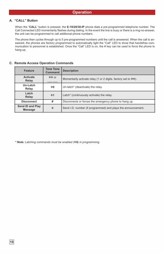
A. “CALL” Button
C. Remote Access Operation Commands
When the “CALL” button is pressed, the E-10/20/30-IP phone dials a pre-programmed telephone number. The
Call Connected LED momentarily flashes during dialing. In the event the line is busy or there is a ring-no-answer,
the unit can be programmed to call additional phone numbers.
The phone then cycles through up to 5 pre-programmed numbers until the call is answered. When the call is an-
swered, the phones are factory programmed to automatically light the “Call” LED to show that handsfree com-
munication to personnel is established. Once the “Call” LED is on, the # key can be used to force the phone to
hang-up.
FeatureTone Tone
CommandDescription
Activate
RelayQQ or
___ ___Momentarily activate relay (1 or 2 digits, factory set to QQ).
Un-Latch
RelayQ0 Un-latch* (deactivate) the relay.
Latch
RelayQ1 Latch* (continuously activate) the relay.
Disconnect # Disconnects or forces the emergency phone to hang up.
Send ID and Play
MessageQ Send I.D. number (if programmed) and plays the announcement.
* Note: Latching commands must be enabled (Q6) in programming.
11
Related Products
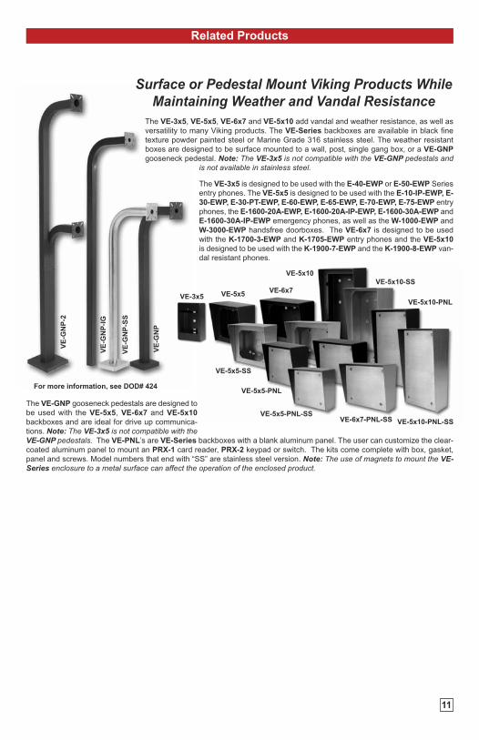
The VE-3x5, VE-5x5, VE-6x7 and VE-5x10 add vandal and weather resistance, as well as
versatility to many Viking products. The VE-Series backboxes are available in black fine
texture powder painted steel or Marine Grade 316 stainless steel. The weather resistant
boxes are designed to be surface mounted to a wall, post, single gang box, or a VE-GNP
gooseneck pedestal. Note: The VE-3x5 is not compatible with the VE-GNP pedestals andis not available in stainless steel.
The VE-3x5 is designed to be used with the E-40-EWP or E-50-EWP Series
entry phones. The VE-5x5 is designed to be used with the E-10-IP-EWP, E-
30-EWP, E-30-PT-EWP, E-60-EWP, E-65-EWP, E-70-EWP, E-75-EWP entry
phones, the E-1600-20A-EWP, E-1600-20A-IP-EWP, E-1600-30A-EWP and
E-1600-30A-IP-EWP emergency phones, as well as the W-1000-EWP and
W-3000-EWP handsfree doorboxes. The VE-6x7 is designed to be used
with the K-1700-3-EWP and K-1705-EWP entry phones and the VE-5x10
is designed to be used with the K-1900-7-EWP and the K-1900-8-EWP van-
dal resistant phones.
The VE-GNP gooseneck pedestals are designed to
be used with the VE-5x5, VE-6x7 and VE-5x10
backboxes and are ideal for drive up communica-
tions. Note: The VE-3x5 is not compatible with theVE-GNP pedestals. The VE-PNL’s are VE-Series backboxes with a blank aluminum panel. The user can customize the clear-
coated aluminum panel to mount an PRX-1 card reader, PRX-2 keypad or switch. The kits come complete with box, gasket,
panel and screws. Model numbers that end with “SS” are stainless steel version. Note: The use of magnets to mount the VE-Series enclosure to a metal surface can affect the operation of the enclosed product.
VE-3x5 VE-5x5VE-6x7
VE-5x10
VE-5x5-PNL-SSVE-6x7-PNL-SS VE-5x10-PNL-SS
VE-5x10-SS
VE-5x5-SS
VE-5x10-PNL
VE-5x5-PNL
VE
-GN
P-2
VE
-GN
P-I
G
VE
-GN
P-S
S
VE
-GN
P
For more information, see DOD# 424
Surface or Pedestal Mount Viking Products WhileMaintaining Weather and Vandal Resistance
Printed in the U.S.A.
IF YOU HAVE A PROBLEM WITH A VIKING PRODUCT, CONTACT: VIKING TECHNICAL SUPPORT AT (715) 386-8666Our Technical Support Department is available for assistance Monday 8am - 4pm and Tuesday through Friday 8am - 5pm central time. So that we can give you bet-ter service, before you call please:1. Know the model number, the serial number and what software version you have (see serial label).2. Have your Technical Practice in front of you.3. It is best if you are on site.
RETURNING PRODUCT FOR REPAIRThe following procedure is for equipment that needs repair:1. Customer must contact Viking's Technical Support Department at 715-386-8666 to obtain a Return Authorization (RA) number. The customer MUST have a com-plete description of the problem, with all pertinent information regarding the defect, such as options set, conditions, symptoms, methods to duplicate problem, fre-quency of failure, etc.2. Packing: Return equipment in original box or in proper packing so that damage will not occur while in transit. Static sensitive equipment such as a circuit boardshould be in an anti-static bag, sandwiched between foam and individually boxed. All equipment should be wrapped to avoid packing material lodging in or stickingto the equipment. Include ALL parts of the equipment. C.O.D. or freight collect shipments cannot be accepted. Ship cartons prepaid to: Viking Electronics, 1531Industrial Street, Hudson, WI 540163. Return shipping address: Be sure to include your return shipping address inside the box. We cannot ship to a PO Box.4. RA number on carton: In large printing, write the R.A. number on the outside of each carton being returned.
RETURNING PRODUCT FOR EXCHANGEThe following procedure is for equipment that has failed out-of-box (within 10 days of purchase):1. Customer must contact Viking’s Technical Support at 715-386-8666 to determine possible causes for the problem. The customer MUST be able to step throughrecommended tests for diagnosis.2. If the Technical Support Product Specialist determines that the equipment is defective based on the customer's input and troubleshooting, a Return Authorization(R.A.) number will be issued. This number is valid for fourteen (14) calendar days from the date of issue.3. After obtaining the R.A. number, return the approved equipment to your distributor, referencing the R.A. number. Your distributor will then replace the Viking prod-uct using the same R.A. number.4. The distributor will NOT exchange this product without first obtaining the R.A. number from you. If you haven't followed the steps listed in 1, 2 and 3,be aware that you will have to pay a restocking charge.
DOD# XXX ZF303590 Rev 2
Due to the dynamic nature of the product design, the information contained in this document is subject to change without notice. Viking Electronics, and its affiliates
and/or subsidiaries assume no responsibility for errors and omissions contained in this information. Revisions of this document or new editions of it may be issued
to incorporate such changes.
Warranty
Product Support: (715) 386-8666
TWO YEAR LIMITED WARRANTYViking warrants its products to be free from defects in the workmanship or materials, under normal use and service, for a period of two years from the date of
purchase from any authorized Viking distributor. If at any time during the warranty period, the product is deemed defective or malfunctions, return the product toViking Electronics, Inc., 1531 Industrial Street, Hudson, WI., 54016. Customer must contact Viking's Technical Support Department at 715-386-8666 to obtain aReturn Authorization (R.A.) number.
This warranty does not cover any damage to the product due to lightning, over voltage, under voltage, accident, misuse, abuse, negligence or any damagecaused by use of the product by the purchaser or others. This warranty does not cover non-EWP products that have been exposed to wet or corrosive environments.This warranty does not cover stainless steel surfaces that have not been properly maintained.
NO OTHER WARRANTIES. VIKING MAKES NO WARRANTIES RELATING TO ITS PRODUCTS OTHER THAN AS DESCRIBED ABOVE AND DISCLAIMSANY EXPRESS OR IMPLIED WARRANTIES OR MERCHANTABILITY OR FITNESS FOR ANY PARTICULAR PURPOSE.
EXCLUSION OF CONSEQUENTIAL DAMAGES. VIKING SHALL NOT, UNDER ANY CIRCUMSTANCES, BE LIABLE TO PURCHASER, OR ANY OTHERPARTY, FOR CONSEQUENTIAL, INCIDENTAL, SPECIAL OR EXEMPLARY DAMAGES ARISING OUT OF OR RELATED TO THE SALE OR USE OF THE PROD-UCT SOLD HEREUNDER.
EXCLUSIVE REMEDY AND LIMITATION OF LIABILITY. WHETHER IN AN ACTION BASED ON CONTRACT, TORT (INCLUDING NEGLIGENCE OR STRICTLIABILITY) OR ANY OTHER LEGAL THEORY, ANY LIABILITY OF VIKING SHALL BE LIMITED TO REPAIR OR REPLACEMENT OF THE PRODUCT, OR ATVIKING'S OPTION, REFUND OF THE PURCHASE PRICE AS THE EXCLUSIVE REMEDY AND ANY LIABILITY OF VIKING SHALL BE SO LIMITED.
IT IS EXPRESSLY UNDERSTOOD AND AGREED THAT EACH AND EVERY PROVISION OF THIS AGREEMENT WHICH PROVIDES FOR DISCLAIMER OFWARRANTIES, EXCLUSION OF CONSEQUENTIAL DAMAGES, AND EXCLUSIVE REMEDY AND LIMITATION OF LIABILITY, ARE SEVERABLE FROM ANYOTHER PROVISION AND EACH PROVISION IS A SEPARABLE AND INDEPENDENT ELEMENT OF RISK ALLOCATION AND IS INTENDED TO BE ENFORCEDAS SUCH.
12
If trouble is experienced with the E-10/20/30-IP phone, for repair or warranty information, please contact: Viking Electronics, Inc., 1531 Industrial Street, Hudson, WI 54016 (715) 386-8666
WHEN PROGRAMMING EMERGENCY NUMBERS AND (OR) MAKING TEST CALLS TO EMERGENCY NUMBERS:Remain on the line and briefly explain to the dispatcher the reason for the call. Perform such activities in the off-peak hours, such as early morning or late evenings.
PART 15 LIMITATIONSThis equipment has been tested and found to comply with the limits for a Class A digital device, pursuant to Part 15 of the FCC Rules. These limits are designed toprovide reasonable protection against harmful interference when the equipment is operated in a commercial environment. This equipment generates, uses, and canradiate radio frequency energy and, if not installed and used in accordance with the instruction manual, may cause harmful interference to radio communications. Op-eration of this equipment in a residential area is likely to cause harmful interference in which case the user will be required to correct the interference at his own ex-pense.