Embed Size (px)
Citation preview

MP
Series
series
Wire-cut EDM SystemsMP Series
K-KL2-4-C0119-A NA1407 Printed in Japan oIPp
* Not all models are supported for all countries and regions.* Machine specifications differ according to the country and region, so please check with your dealer.* Processing data provided in this brochure is for reference only.
HEAD OFFICE: TOKYO BLDG., 2-7-3, MARUNOUCHI, CHIYODA-KU, TOKYO 100-8310, JAPANNAGOYA WORKS: 1-14, YADA-MINAMI, 5-CHOME, HIGASHI-KU, NAGOYA 461-8670, JAPAN
New publication, effective Jul. 2014.Specifications are subject to change without notice.
Mitsubishi Electric Corporation Nagoya Works is a factory certified for ISO14001 (standards for environmental management systems) and ISO9001(standards for quality assurance management systems)

New generation makes it's mark ina continuously updated lineage
1980
1990
2000
2014
1972DWC50H-DNC2 DWC100H-CNC2 DWC90-CNC1DWC50S-LT1 DWC90FSK-CNC1 DWC90G DWC90H DWC90PH DWC110PH DWC90CDWC110N-CNC1
PX05 DWC90HADWC90SBDWC110SZDWC110SADWC400HASX20CX20DWC90PAFX10
FX20K QA20 RA90AT FA20P PA20 FA30V PA05S
PA10 ADVANCE
FA20S
FA50V
FA10PS
BA8 FA20S AdvanceNA2400P
FA20
Line tracer typewire-cut EDM
Line tracer typewire-cut EDM Taper machining unitTaper machining unit Max. machining speed 60mm2/minMax. machining speed 60mm2/min
Max. machining speed 110mm2/minOptimum surface roughness of Rz2µm
Max. machining speed 110mm2/minOptimum surface roughness of Rz2µm Automatic wire threading unit (water jet type)Automatic wire threading unit (water jet type)
32 bit CNC32 bit CNCAutomatic wire threading unit "AF2"Automatic wire threading unit "AF2"Anti-electrolysis power supply
(AE power supply)Anti-electrolysis power supply
(AE power supply)Ultrahigh accuracy wire-cut EDM (Full-cabin)Ultrahigh accuracy wire-cut EDM (Full-cabin)
64 bit CNC64 bit CNC World's fastest "V500" power supply World's fastest "V500" power supply Super fine finishing power supply "Digital-FS"Super fine finishing power supply "Digital-FS"
Large-sized wire-cut EDMLarge-sized wire-cut EDMDigital-AE power supplyDigital-AE power supply
MX600
Oil wire-cut EDMOil wire-cut EDM
Max. machining speed 325mm2/minAutomatic wire threading unit "AT"
Max. machining speed 325mm2/minAutomatic wire threading unit "AT"
Max. machining speed 250mm2/minMax. machining speed 250mm2/min
MV1200R
MITSUBISHI ELECTRIC Wire-cut EDM Systems
MPSeries1 2

Wire-cut EDM to meet to anticipations for ultrahigh accuracy
MPSeries
MV-R SeriesHigh-performance model innovatingnext-generation high-performance machine
High-performance machine
MV-S SeriesStandard model pursuing a cost performance standard machine
High-productivity machine
Oil
Micro slit width 23µm
Flagship model incorporating extreme precision machining
PA05SADVANCE
Ultrahigh accuracy machines
MX 600Flagship model incorporating extreme precision machining
MP SeriesHigh-class model incorporating a ultra-high accuracy machining
Wire-cut EDM Systems Line up Model line-up covers your machining needs
from piece parts to super-accurate mold making
3 4

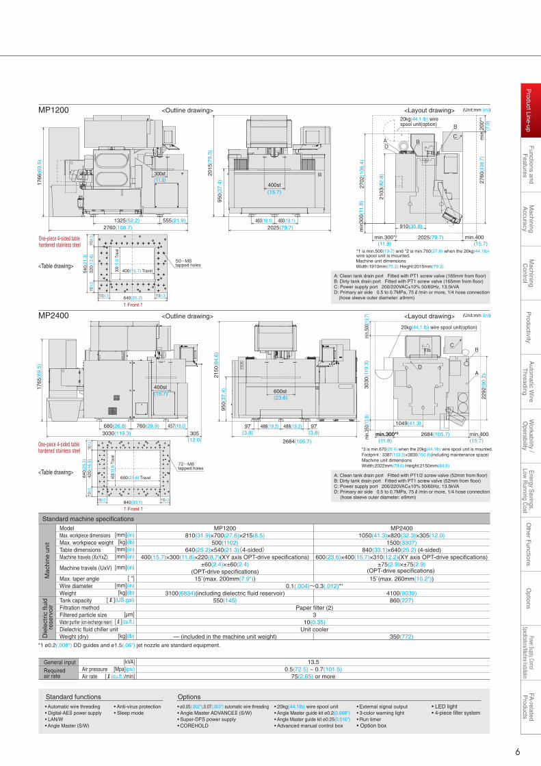
(Unit:mm (in))MP1200
Standard functions• Automatic wire threading• Digital-AEⅡ power supply• LAN/W• Angle Master (S/W)
• Anti-virus protection• Sleep mode
• 20kg(44.1lb) wire spool unit• Angle Master guide kit ø0.2(0.008")• Angle Master guide kit ø0.25(0.010")• Advanced manual control box
• External signal output• 3-color warning light• Run timer• Option box
• LED light• 4-piece filter system
• ø0.05(.002"),0.07(.003") automatic wire threading• Angle Master ADVANCEⅡ (S/W)• Super-DFS power supply• COREHOLD
Options
MP1200
Product Line-upProduct Line-up
<Outline drawing> <Layout drawing>
One-piece 4-sided tablehardened stainless steel
Front
<Table drawing>
<Table drawing>
One-piece 4-sided tablehardened stainless steel
Front
Four-sided hardened table
4-axis LSM (XYUV linear shaft motor)
(Automatic elevation tank)
*1 ø0.2(.008") DD guides and ø1.5(.06") jet nozzle are standard equipment.
ModelMax. workpiece dimensionsMax. workpiece weightTable dimensionsMachine travels (XxYxZ)
Machine travels (UxV)
Max. taper angleWire diameterWeightTank capacityFiltration methodFiltered particle sizeWater purifier (ion exchange resin)Dielectric fluid chiller unitWeight (dry)
[mm](in)
[kg](lb)[mm](in)[mm](in)
[mm](in)
[ °][mm](in)
[kg](lb)[R](US gal)
[µm][R](cu.ft.)
[kg](lb)
Air pressureAir rate
13.50.5(72.5) ~ 0.7(101.5)
75(2.65) or more
[kVA][Mpa](psi)
[R(cu.ft.)/min]Required air rate
General input
MP1200810(31.9)×700(27.6)×215(8.5)
500(1102)640(25.2)×540(21.3)(4-sided)
400(15.7)×300(11.8)×220(8.7)(XY axis OPT-drive specifications)±60(2.4)×±60(2.4)
(OPT-drive specifications)15˚(max. 200mm(7.9"))
3100(6834)(including dielectric fluid reservoir)550(145)
— (included in the machine unit weight)
MP24001050(41.3)×820(32.3)×305(12.0)
1500(3307)840(33.1)×640(25.2) (4-sided)
600(23.6)×400(15.7)×310(12.2)(XY axis OPT-drive specifications)±75(2.9)×±75(2.9)
(OPT-drive specifications) 15˚(max. 260mm(10.2"))
4100(9039)860(227)
350(772)
0.1(.004)~0.3(.012)*1
Paper filter (2)3
10(0.35)Unit cooler
Standard machine specifications
MP24004-axis LSM (XYUV linear shaft motor)
Four-sided hardened table
2015
(79.
3)
950(
37.4
)
400st(15.7)
2025(79.7)460(18.1)460(18.1)
2760(108.7)555(21.9)
300st(11.8)
1325(52.2)
1766
(69.
5)
2025(79.7)
910(35.8)
B
BA
2103
(82.
8)
2760
(108
.7)
2702
(106
.4)
min
300(
11.8
)
min
.200
*1
D
C
min.300*2 min.400min.400
(Unit:mm (in))MP2400 <Outline drawing> <Layout drawing>
20kg(44.1 lb) wire spool unit(option)
min.
500(
19.7
)30
30(1
19.3
)m
in.3
50(1
3.8)
2292
(90.
2)
min.400(15.7)
D
B
A
C
2684(105.7)
1049(41.3)
min.300*3min.300*3
600st(23.6)
950(
37.4
)
2684(105.7)
488(19.2)97(3.8)
97(3.8)
488(19.2)
2150
(84.
6)
305(12.0)
400st(15.7)
1765
(69.
5)
3030(119.3)680(26.8) 760(29.9) 457(18.0)
80(3
.1")
5
(0.2")
5
(0.2
")
5
(0.2")
5
(0.2
")
5
(0.2")
5
(0.2
")
5
(0.2")
5
(0.2
")
80(3
.1")
100(3.9")
Thickness : 20mm(0.79")Unit : mm
100(3.9")
30(1.2")
• Workpiece:Steel (PD613 t20mm(0.79") (SKD11 improved steel))HRC56-57 after quenching the workpiece,sub-zero treatment, high thermal tempering, stabilizing treatment and demagnetization are conducted.
• Wire electrode: φ0.2(.008")/BS• Room temperature: 20°C±1°C
Machining accuracy ±2µm achieved (Note 1)
(Note 1) The machining accuracy follows the Mitsubishi Electric machining conditons
Machining accuracy ±2µm achieved (Note 1)
(Note 1) The machining accuracy follows the Mitsubishi Electric machining conditons
(Automatic elevation tank)
110(4.3)110(4.3)
420(
16.5
)110
(4.3)
110(4.
3)64
0(25
.2)
840(33.1)
400(
15.8
) Tra
vel
600(23.6) Travel
72-M8 tapped holes
50-M8 tapped holes
110(4.3) 110(4.3)
110(4
.3)11
0(4.3)
540(
21.3
)32
0(12
.6)
640(25.2)
300(
11.8
) Tra
vel
400(15.7) Travel
20kg(44.1 lb) wire spool unit(option)
(7.9
)
(11.8) (15.7)
(11.8)
Footprint : 3387(133.3)×3830(150.8)(including maintenance space)Machine unit dimensionsWidth:2022mm(79.6) Height:2150mm(84.6)
*3 is min.670(26.4) when the 20kg(44.1lb) wire spool unit is mounted.
Machine unit dimensionsWidth:1910mm(75.2) Height:2015mm(79.3)
*1 is min.500(19.7) and *2 is min.700(27.6) when the 20kg(44.1lb) wire spool unit is mounted.
A: Clean tank drain port Fitted with PT1 screw valve (165mm from floor)B: Dirty tank drain port Fitted with PT1 screw valve (165mm from floor) C: Power supply port 200/220VAC±10% 50/60Hz, 13.5kVAD: Primary air side 0.5 to 0.7MPa, 75R/min or more, 1/4 hose connection
(hose sleeve outer diameter: ø9mm)
Mac
hine
uni
tD
iele
ctric
flui
d r
eser
voir
A: Clean tank drain port Fitted with PT1/2 screw valve (52mm from floor)B: Dirty tank drain port Fitted with PT1 screw valve (52mm from floor) C: Power supply port 200/220VAC±10% 50/60Hz, 13.5kVAD: Primary air side 0.5 to 0.7MPa, 75R/min or more, 1/4 hose connection
(hose sleeve outer diameter: ø9mm)
5 6
Other F
unctionsO
ptionsW
orkability / O
perabilityA
utomatic W
ire T
hreadingP
roductivityM
achining A
ccuracyF
unctions and F
eaturesP
roduct Line-upFA
-related P
roductsM
achining C
ontrolPower Supply, Control
Specifications/Machine InstallationE
nergy Savings,
Low R
unning Cost
Product Line-up

Functions and FeaturesFunctions and FeaturesFully equipped with useful functions for the manufacturing workplace, featuring refined style,high performance, energy savings, simple operation and vast expertiseFully equipped with useful functions for the manufacturing workplace, featuring refined style,high performance, energy savings, simple operation and vast expertise
Security
Machiningspeed
Energysavings
Corneraccuracy
Circularaccuracy
MP1200/MP2400MP1200/MP2400
Energy savings, low running costEnergy savings, low running costOperabilityOperabilityAutomatic wire threadingAutomatic wire threading
Refer to page 19Refer to page 19
Refer to page 17-18Refer to page 17-18
• Search function for machining conditions is improved by a narrow-down function
• Job scheduling adjustments use the schedule call back, extra job insertion and ME-pack feature
*ME-pack is a package of machining processes including offset, machining speed and adaptive control setting
• Power consumption reduced up to 69%
• Wire consumption reduced up to 46%
• Filter cost reduced up to 45%(Automatic changing filtration flow rate)
Machining condition search screen
3D CAM screen
Conventionalmodel
MP ,45%OFF,45%OFF
*Compared to conventional Mitsubishi ElectricWire-cut EDM (FA Series)
Machining accuracyMachining accuracy
• New annealing system greatly improves wire threading with a curl ratio of less than 10%
• Wire break point insertion is greatly improved for thick workpieces
• Wire threading suitable for workpiece shape (i.e., jet stream on, jet stream off and submerged break point insertion)
• Equipped with a linear shaft motor (LSM)
• Circular accuracy within 1µm is realized using optical drive system (ODS)
Refer to page 15-16Refer to page 15-16
Refer to page 9-11Refer to page 9-11
WorkabilityWorkability
• 3-sided elevating work-tank• Compatible with workpiece
automatic changing using a robotic system
Refer to page 17-18Refer to page 17-18
ProductivityProductivity
Refer to page 13-14Refer to page 13-14
• High-speed machining is enhanced by improved power supply for fine surface finish machining
Machining time comparison for Rz1.2µm/Ra0.15µm/6µ"Ra
*Compared to conventional Mitsubishi ElectricWire-cut EDM (NA Series)
Wire electrode : ø0.2(.008")/BS
Workpiece : Steel(SKD11), t60mm(2.4")
Pitch / shape accuracy ±1µm(.00004")
Circular accuracy 0.8µm(.00003")
Optimum surface Rz0.6µm/Ra0.12µm/5µ"Ra (steel)
Taper accuracy ±0.01 degree
Conventionalmodel
MP ,46%OFF,46%OFF
Conventionalmodel
MP ,69%OFF,69%OFF
Highly accurate machining is realized
Conventionalmodel
MP 10%OFF ,10%OFF ,
Servo amplifierServo amplifier
ADVANCE control unitADVANCE control unit
LSM with linear glass scale feedbackLSM with linear glass scale feedback
LSM with linear glass scale feedbackLSM with linear glass scale feedback
7 8
Other F
unctionsO
ptionsW
orkability / O
perabilityA
utomatic W
ire T
hreadingP
roductivityM
achining A
ccuracyF
unctions and F
eaturesP
roduct Line-upFA
-related P
roductsM
achining C
ontrolPower Supply, Control
Specifications/Machine InstallationE
nergy Savings,
Low R
unning Cost
Functions and F
eatures

Servo amplifier(in-house product)
Servo amplifier(in-house product)
Linear shaft motor with linear glass scale feedbackLinear shaft motor with linear glass scale feedback
ADVANCE control unitADVANCE control unit
Linear shaft motor with linear glass scale feedback
Linear shaft motor with linear glass scale feedback
Opt Drive SystemMachining Accuracy
Highly rigid structure
Next-generation drive system and optimum machine structure
Circular accuracy● Circular accuracy of 0.98µm(.00004") is realized for circular machining of φ80mm(3.1")
● Tracing accuracy is improved by servo control (AFCⅢ)
●MP1200 employs a split X/Y-axis construction method allowing both to be directly mounted to the T-shaped base casting for optimum stability. This combination moves the table in the X-axis and the column in the Y-axis.
●MP2400 utilizes a fixed table traveling column design for improved accuracy in large heavy workpieces.
X-axis pitch error
Y-axis pitch error
Accuracy measurement of circular machining
Axis movement accuracy ●Ultra-high accuracy linear guides are carefully installed
on precisely machined mounting surfaces to provide a linear straightness of 1 - 2µm.
●This effort ensures precise linear movement by reducing waving of the linear guide.
Pitch accuracy
Circular accuracy measurement of machine
●A chiller system is used to cool the dielectric fluid to remove the heat generated by the EDM machining process.
●This process is synchronized through thermal sensors on the machine casting while circulating the fluid through key areas of the machine structure (Thermal buster).
Thermal Stability System
Temperature of machine structure (Z-axis base) and lower arm
Pitch accuracy adjustment function
Wire electrode: φ0.2(.008")/BS Workpiece: Steel (SKD11) t30mm(1.18")
After quenching the workpiece, sub-zero treatment, high thermal tempering, stabilizing treatment and demagnetization are conducted.
Surface roughness: Rz1.8µm/Ra0.22µm/9µ”RaRoom temperature: ±0.5°C
Wire electrode: φ0.2(.008")/BS Workpiece: Steel (SKD11) t30mm(1.18")
<Pitch accuracy>x-axis ±1µm
(.00004")Y-axis ±1µm
(.00004")
● Ultra-high accuracy machining is realized using the Optical Drive System (ODS).
● Stable ultra-high accuracy machining is realized through improvements in axes movement and thermal stability control.
室温 機械本体
Optical Drive System●High-speed fiber-optic communications and a
linear shaft motor synergistically improve machining accuracy
●A servo amplifier and control unit developed by Mitsubishi Electric contribute to system optimization
Linear Shaft Motor●Power consumption is reduced by utilizing a full
360° magnetic flux as the effective driving force●Highly accurate axis movement is possible
without any backlash●Non contact power transmission ensures stable
and accurate axis movement for many years
A6
120mm(4.7")280mm(11.0")
400mm(15.7")
260mm(10.2")
A5 A4
A1 A2 A3
Temperature control of X axis linear shaft motor and machine structure (table)(synchronized with dielectric fluid temperature)
Dielectric fluid reservoir
Temperature control of lower arm and working tank (synchronized with dielectric fluid temperature)
Temperature control of machine Structure (z-axis base)(synchronized with dielectric fluid temperature)
Temperature control of Y axis linear shaft motor and machine structure (column)(synchronized with dielectric fluid temperature)
High circular accuracy realized in entire XY stroke area
Circular machining of φ80mm(3.1")
● Electronic pitch error compensation, measured by laser interferometer, can be entered to achieve ultra-high machining accuracy.
16
18
20
22
24
0 20 40 60 80 100 120 140 160 180
Lower arm Z-axis base
Circular machining of φ20mm(0.79")
180° 0°
90°
180° 0°
270°
90°
真円度PーP=0.98µm
1µm
(×10000) 270°真円度PーP=0.76µm
1µm
(×10000)
Magnet
Magnetic flux
N S NN NS
Utilizes all magnetic flux as an effective driving force.
Shaft Magnet Coil Coil
Fiber-optic communication
Tem
pera
ture
Time
Upper Middle Bottom
Upper Middle Bottom
[mm]
[mm]
109

Servo amplifier(in-house product)
Servo amplifier(in-house product)
Linear shaft motor with linear glass scale feedbackLinear shaft motor with linear glass scale feedback
ADVANCE control unitADVANCE control unit
Linear shaft motor with linear glass scale feedback
Linear shaft motor with linear glass scale feedback
Opt Drive SystemMachining Accuracy
Highly rigid structure
Next-generation drive system and optimum machine structure
Circular accuracy● Circular accuracy of 0.98µm(.00004") is realized for circular machining of φ80mm(3.1")
● Tracing accuracy is improved by servo control (AFCⅢ)
●MP1200 employs a split X/Y-axis construction method allowing both to be directly mounted to the T-shaped base casting for optimum stability. This combination moves the table in the X-axis and the column in the Y-axis.
●MP2400 utilizes a fixed table traveling column design for improved accuracy in large heavy workpieces.
X-axis pitch error
Y-axis pitch error
Accuracy measurement of circular machining
Axis movement accuracy ●Ultra-high accuracy linear guides are carefully installed
on precisely machined mounting surfaces to provide a linear straightness of 1 - 2µm.
●This effort ensures precise linear movement by reducing waving of the linear guide.
Pitch accuracy
Circular accuracy measurement of machine
●A chiller system is used to cool the dielectric fluid to remove the heat generated by the EDM machining process.
●This process is synchronized through thermal sensors on the machine casting while circulating the fluid through key areas of the machine structure (Thermal buster).
Thermal Stability System
Temperature of machine structure (Z-axis base) and lower arm
Pitch accuracy adjustment function
Wire electrode: φ0.2(.008")/BS Workpiece: Steel (SKD11) t30mm(1.18")
After quenching the workpiece, sub-zero treatment, high thermal tempering, stabilizing treatment and demagnetization are conducted.
Surface roughness: Rz1.8µm/Ra0.22µm/9µ”RaRoom temperature: ±0.5°C
Wire electrode: φ0.2(.008")/BS Workpiece: Steel (SKD11) t30mm(1.18")
<Pitch accuracy>x-axis ±1µm
(.00004")Y-axis ±1µm
(.00004")
● Ultra-high accuracy machining is realized using the Optical Drive System (ODS).
● Stable ultra-high accuracy machining is realized through improvements in axes movement and thermal stability control.
室温 機械本体
Optical Drive System●High-speed fiber-optic communications and a
linear shaft motor synergistically improve machining accuracy
●A servo amplifier and control unit developed by Mitsubishi Electric contribute to system optimization
Linear Shaft Motor●Power consumption is reduced by utilizing a full
360° magnetic flux as the effective driving force●Highly accurate axis movement is possible
without any backlash●Non contact power transmission ensures stable
and accurate axis movement for many years
A6
120mm(4.7")280mm(11.0")
400mm(15.7")
260mm(10.2")
A5 A4
A1 A2 A3
Temperature control of X axis linear shaft motor and machine structure (table)(synchronized with dielectric fluid temperature)
Dielectric fluid reservoir
Temperature control of lower arm and working tank (synchronized with dielectric fluid temperature)
Temperature control of machine Structure (z-axis base)(synchronized with dielectric fluid temperature)
Temperature control of Y axis linear shaft motor and machine structure (column)(synchronized with dielectric fluid temperature)
High circular accuracy realized in entire XY stroke area
Circular machining of φ80mm(3.1")
● Electronic pitch error compensation, measured by laser interferometer, can be entered to achieve ultra-high machining accuracy.
16
18
20
22
24
0 20 40 60 80 100 120 140 160 180
Lower arm Z-axis base
Circular machining of φ20mm(0.79")
180° 0°
90°
180° 0°
270°
90°
真円度PーP=0.98µm
1µm
(×10000) 270°真円度PーP=0.76µm
1µm
(×10000)
Magnet
Magnetic flux
N S NN NS
Utilizes all magnetic flux as an effective driving force.
Shaft Magnet Coil Coil
Fiber-optic communication
Tem
pera
ture
Time
Upper Middle Bottom
Upper Middle Bottom
[mm]
[mm]
109
Other F
unctionsO
ptionsW
orkability / O
perabilityA
utomatic W
ire T
hreadingP
roductivityM
achining A
ccuracyF
unctions and F
eaturesP
roduct Line-upFA
-related P
roductsM
achining C
ontrolPower Supply, Control
Specifications/Machine InstallationE
nergy Savings,
Low R
unning Cost
Machining
Accuracy

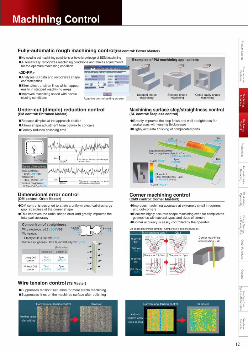
Corner machining control (CM3 control: Corner Master3)
●Improves machining accuracy at extremely small in-corners and out-corners
●Realizes highly accurate shape machining even for complicated geometries with several types and sizes of corners
●Corner accuracy is easily controlled by the operator
Wire tension control (TS Master)
●Suppresses tension fluctuation for more stable machining●Suppresses lines on the machined surface after polishing
Conventional corner control CM3
(R0.2mm)(.008")
(R0.15mm)(.006")
Shape error: 2 to 3µm Shape error: 1µm
In-corner60˚
In-corner90˚
Analysis of
machined surface
before polishing
Under-cut (dimple) reduction control(EM control: Entrance Master)
●Reduces dimples at the approach section●Allows shape adjustment from convex to concave●Greatly reduces polishing time
Machining surface step/straightness control(SL control: Stepless control)
●Greatly improves the step finish and wall straightness for workpieces with varying thicknesses
●Highly accurate finishing of complicated parts
Dimensional error control(OM control: Orbit Master)
●OM control is designed to attain a uniform electrical-discharge gap regardless of the corner shape
●This improves the radial shape error and greatly improves the total part accuracy
Fully-automatic rough machining control(PM control: Power Master)
●No need to set machining conditions or have knowledge of EDM machining●Automatically recognizes machining conditions and makes adjustments
for the optimum machining condition
<3D-PM>●Analyzes 3D data and recognizes shape
characteristics●Eliminates transition lines which appear
easily in stepped machining areas●Improves machining speed with nozzle
closing conditionsStepped shape
machiningStepped shape
machiningCross-cavity shape
machining
Examples of PM machining applications
Dimple
Example of die machining
2µm
250µm
2µm
250µmEM control: concave section depth within surface roughnessEM control: concave section depth within surface roughness
No control: concave section depth approx. 4µmNo control: concave section depth approx. 4µm
Wire electrode: ø0.2 (.008")/BSWorkpiece:
Steel(SKD11), t60mm (2.4")Surface roughness : Rz2.0µm/Ra0.28µm/11µ"Ra
B:4mm(.16")
A:5mm(.20")
Section A Section B
3µm(.0001")
3µm(.0001")
3µm(.0001")
5µm(.0002")
Using OM control
Without OM control
(Both sides)
Conventional control: Step, straightness -3µm to +7µm (-.0001 to +.0003")
7µm(.0003")
3µm(.0001")
1µm(.00004")
2µm(.00008")
SL control: Step, straightness +2µm (+.00008") or less
7.0µm(.0003")
-7.0µm(-.0003")
Adaptive control setting screen
Wire electrode :ø0.2 (.008")/BS
Workpiece :Steel, t20mm(.79")
Surface roughness :Rz3.9µm/Ra0.5µm/20µ"Ra
Corner machiningcontrol using CM3
1ランク上の技術により高付加価値加工を実現
Taper accuracy●Taper accuracy of ±0.01° and
dimensional accuracy of ±5µm are realized
●ODS provides high accuracy even when cutting a UV independent tapered shape
●Taper accuracy is improved regardless of wire angle direction using Angle Master ADVANCEⅡ
Angle Master ADVANCE@●Taper angle accuracy is
more consistent in all tilt directions.
Highly accurate pick-up positioning●Workpiece pick-up positioning error is reduced
Machining accuracy of thick workpiece●Shape accuracy of ±2µm(.00008") is possible even with a
130mm(5.1") thick workpiece●High straight-line accuracy is realized using shape control
power supply (Digital-AEⅡ)●Surface roughness of Rz1.5µm/Ra0.18µm/7µ"Ra is
realized using Super-DFS power supply (Super Digital-FS power supply)
Shape control power supply (Digital-AE@)●Wire straightness is digitally controlled with
electrical-discharge position control ●Straightness accuracy is improved during rough, intermediate
and finishing processes
Super-DFS power supply (Super Digital-FS power supply)●Optimum surface
roughness of Rz0.6µm/Ra0.08µm/3µ"Ra (steel)
●Machining with the workpiece set directly on the table
(insulation jig not required)●Machining range not limited
(entire XY stroke area)
Wire electrode: φ0.2(.008")/BS
Workpiece: Steel (SKD11)
Surface roughness: Rz1.5µm/Ra0.18µm/7µ"Ra
Opt Drive SystemMachining Accuracy Machining Control
Digital-AE@
1
2
3
4
5
020 60 100 150 200
Workpiece thickness [mm]
Sur
face
rou
ghne
ss [µ
mR
z]
H-FS(Standard)H-FS(Standard)
DFS(option for MV)DFS(option for MV)
MV MV
<Steel> <Steel>
Improved surface finish using H-FS power supply
1
2
3
4
5
020 60 100 150 200
Workpiece thickness [mm]
Sur
face
rou
ghne
ss [µ
mR
z]
Super-DFS(option)Super-DFS(option)
MV MV
<Steel> <Steel>
Improved surface finish for thick workpieces
Improved surface finish using Zn wire and Super-DFS
DFS(option for MV) DFS(option for MV)
Conventional tension control TS master
Machined surface
after polishing
Conventional tension control TS master
H-FS power supply (High Power FS power supply)●Optimum surface
roughness of Rz1.2µm/Ra0.15µm/6µ"Ra (steel)
0 5 10 15
100mmt
200mmt
Straightness accuracy (both sides) µm
Comparison of straightness accuracy during finish machining
Compared to conventional Mitsubishi Electric Wire-cut EDM (FA Series)
Conventional model
Digital-AE@
Straight part Taper 10 degree part
Wire electrode: φ0.2(.008")/BS Workpiece: Steel (SKD11) t20mm(0.79")
Lower opening
Upper opening
Measuring jig Angle Master ADVANCE2 screen
0.020
0.010
0.015
0
-0.005
0.005
-0.010
-0.015
-0.020
Dimension error
Dim
ensi
on e
rror
[mm
]
Dimension error of upper opening top surfaceDimension error of lower opening bottom surface
0.020
0.015
0.010
0.005
0
-0.005
-0.010
-0.015
-0.020
Ang
le e
rror
[°]
Angle error
Upper opening angle error
Improved performance area on MP series
Improved performance area on MP series
Conventional technology
• Machining conditions are optimized
• Number of cuts are increased
• Upper/lower dimension difference is compensated mechanically (taper angle)
Sha
pe c
ontr
olpo
wer
sup
ply
Discharge rate relative to workpiece thickness is monitored by electrical-discharge position control
Wire electrode: ø0.25mm(.010")Workpiece: SteelNo. of cuts: 5
Comparison of straightness
In-corner60˚
In-corner90˚
Die-shaped machining samples Comparison of corner accuracies
11 12
Other F
unctionsO
ptionsW
orkability / O
perabilityA
utomatic W
ire T
hreadingP
roductivityM
achining A
ccuracyF
unctions and F
eaturesP
roduct Line-upFA
-related P
roductsM
achining C
ontrolPower Supply, Control
Specifications/Machine InstallationE
nergy Savings,
Low R
unning Cost
Machining C
ontrolM
achining A
ccuracy

Precise Finish CircuitProductivity
High-speed anti-electrolysis power supply (AE power supply)
●Electrolytic corrosion is suppressed, preventing the formation of soft layers
●Compatible with all power circuits, from rough machining to finish machining
●High-speed, safe unmanned machining possible using water
High-speed machining is enhanced by improved power supply for fine surface finish machining
Oil machiningWater machining
CrackCrack
Comparison of water- and oil- machined surfacesComparison of AE and DC power-supply machining
* Photo shows a comparison under adverse conditions where electrolysis occurs easily
DC power-supplymachining
AE power-supply machining
Titanium alloy
DC power-supply machining
AE power-supply machining
Brass
DC power-supplymachining
AE power-supply machining
Aluminum
Table insulation●Insulated worktable ensures improved surface finishing
●Stable machining realized when using short-pulse and low-voltage machining conditions
Conventionalmodel
MP
Machining time comparison for Rz1.2µm/Ra0.15µm/6µ"Ra
0 100(%)
Machining samples
Surface roughness
Improved Productivity
Hardenedtable
Ceramic
Casting
Wire guide ●Flow analysis simulation has been used to optimize the
water flow through the guide, enhancing cutting speed by improving sludge removal from the gap
High-speed digital control●Spark detection speed (up to twice as fast as our
conventional model) provides improved discharge efficiency and suppresses wire breakage simultaneously while improving machining speed
,Reduced 10%,Reduced 10%
*Compared to conventional Mitsubishi Electric Wire-cut EDM (NA Series)
Wire electrode : ø0.2(.008")/BSWorkpiece : Steel(SDK11), t60mm(2.4")
Water flow distortedWater flow distorted
No water flow distortionNo water flow distortion
Non-optimized wire guide structureNon-optimized wire guide structure
Optimized wire guide structureOptimized wire guide structure
A-A cross-sectionA-A cross-section
↑A
↑A
AE power-supply machining
AE power-supply machining
Workpiece topWorkpiece top Workpiece topWorkpiece top
Machined surfaceMachined surface
DC power-supply machining
DC power-supply machiningMachined surfaceMachined surface
Edg
e
Mac
hine
dsu
rfac
eM
achi
ned
cros
s-se
ctio
n
Mac
hine
dsu
rfac
eM
achi
ned
cros
s-se
ctio
n
13 14
Other F
unctionsO
ptionsW
orkability / O
perabilityA
utomatic W
ire T
hreadingP
roductivityM
achining A
ccuracyF
unctions and F
eaturesP
roduct Line-upFA
-related P
roductsM
achining C
ontrolPower Supply, Control
Specifications/Machine InstallationE
nergy Savings,
Low R
unning Cost
Productivity

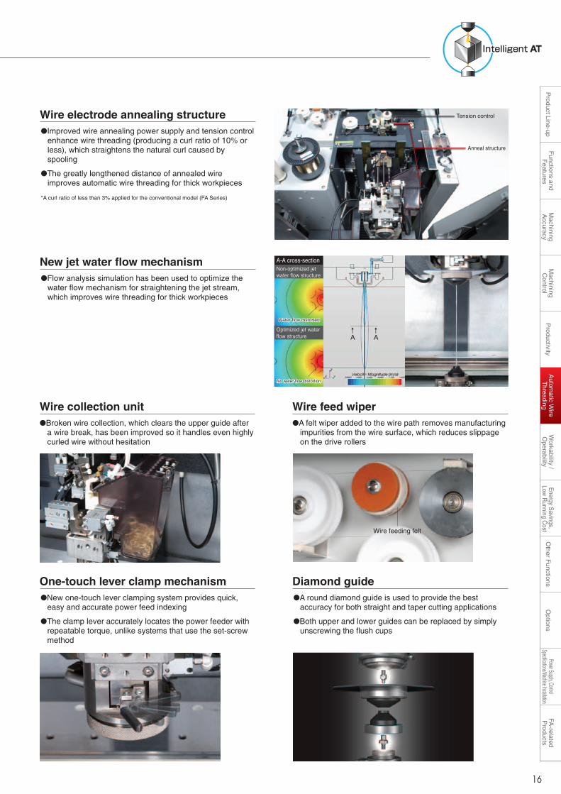
Intelligent AT
New jet water flow mechanism●Flow analysis simulation has been used to optimize the
water flow mechanism for straightening the jet stream, which improves wire threading for thick workpieces
Wire electrode annealing structure●Improved wire annealing power supply and tension control
enhance wire threading (producing a curl ratio of 10% or less), which straightens the natural curl caused by spooling
●The greatly lengthened distance of annealed wire improves automatic wire threading for thick workpieces
*A curl ratio of less than 3% applied for the conventional model (FA Series)
Automatic Wire ThreadingAdvanced technology for greatly improved productivity
Improved automatic wire threading●New annealing system greatly improves wire threading with a curl ratio of less than 10%
●Wire break point insertion is greatly improved for thick workpieces
●Wire threading suitable for workpiece shape (i.e., jet stream on, jet stream off and submerged break point insertion)
●Automatic threading time is reduced by up to 35% when using AT high-speed mode (includes one wire cut and insertion cycle)
One-touch lever clamp mechanism●New one-touch lever clamping system provides quick,
easy and accurate power feed indexing
●The clamp lever accurately locates the power feeder with repeatable torque, unlike systems that use the set-screw method
Diamond guide●A round diamond guide is used to provide the best
accuracy for both straight and taper cutting applications
●Both upper and lower guides can be replaced by simply unscrewing the flush cups
Wire collection unit●Broken wire collection, which clears the upper guide after
a wire break, has been improved so it handles even highly curled wire without hesitation
Wire feed wiper●A felt wiper added to the wire path removes manufacturing
impurities from the wire surface, which reduces slippage on the drive rollers
Tension control
Anneal structure
Wire feeding felt
Water flow distortedWater flow distorted
No water flow distortionNo water flow distortion
Non-optimized jet water flow structureNon-optimized jet water flow structure
A-A cross-sectionA-A cross-section
Optimized jet water flow structureOptimized jet water flow structure
↑A
↑A
Wire break point insertion is possible Multiple level wire threading is possible by setting the AT jet mode to off.Highly dependable automatic threading for multi-opening applications
Stable automatic threading is realized during pitch machining
15 16
Other F
unctionsO
ptionsW
orkability / O
perabilityA
utomatic W
ire T
hreadingP
roductivityM
achining A
ccuracyF
unctions and F
eaturesP
roduct Line-upFA
-related P
roductsM
achining C
ontrolPower Supply, Control
Specifications/Machine InstallationE
nergy Savings,
Low R
unning Cost
Autom
atic Wire
Threading

Natural User Inter faceAuto & Easy setupWorkability / Operability
Wire travel system
●A large access window into the fluid tank provides easy entry for cleaning
Dielectric fluid supply unit
●Chiller air filter
Unit cooler filter
User-friendly features ensure easy operation
Ergonomic design●User-friendly keyboard and mouse●Easy-to-view screen (15-inch)●Intuitive operations using touch-panel control
●Easily read the filter pressure●The convenient location of the
jet cleaning nozzle makes tank clean-up easy
Filter pressure gauge and jet cleaning nozzle
●Conveniently located at the front for easy maintenance
Hardened table and all stainless steel structure●Equipped with a hardened
table●The working tank and
dielectric supply unit are made of stainless steel
●Resistant to deterioration by dielectric fluid and sludge
●The stability of the wire tensioning system is improved by a felt wiper and felt keeper pads that eliminate the chance of the wire jumping off the rollers
Felt wiper and felt keeper padsFelt wiper and felt keeper pads
Dielectric fluid flow meter and jet flow adjustment valve●Dielectric flow meters are easy to read●The adjustable jet flow valve increases the
range of work that can be done
Flat power feed terminal●The flat shape makes it easy to index to the
next location
●The machine table can be reached from three sides making workpiece setups quick and easy
3-sided elevating work-tank
●Highly accurate wire alignment is easy using the wire-alignment device (optional)
●Taper parameter set-up is simple using the wire-alignment device
Wire alignmentCleaning mechanism <MP2400>
●A forced-flush self-cleaning mechanism prevents sludge from sticking to the stainless-steel seal plate
Broken wire collection box
A total of 48 index locations can be used (24 on each side)
24 index locations on each side
●Outstanding graphics supporting easy operation
Set-up screen
Work piece pick-up positioning Machining condition search function●Interactive operation easily creates NC data with machining
condition●Job scheduling adjustment uses the schedule call back,
extra job insertion and ME-pack feature*ME-pack is a package of machining processes including offset, machining speed and adaptive control setting
●Highly accurate workpiece pick-up positioning is possible with the water flow on or when a workpiece is submerged
●Reads and displays 3D CAD data (Parasolid format *1) with a built-in 3D CAM
●Extracts 3D model contours with a built-in 3D CAM●Creates NC data including machining conditions (ME-pack),
through the built-in CAM system●3D-PM improves machining performance by (3D model
shape analysis and optimum machining control)
Advanced 3D data for machine control
*1 Parasolid is a registered trademark of UGS PLM Solutions Co., Ltd.
Work alignment function●By measuring the workpiece flatness with a dial indicator, the
wire tilt can be automatically compensated to match the angle of the part, further reducing set-up time
17 18
Other F
unctionsO
ptionsW
orkability / O
perabilityA
utomatic W
ire T
hreadingP
roductivityM
achining A
ccuracyF
unctions and F
eaturesP
roduct Line-upFA
-related P
roductsM
achining C
ontrolPower Supply, Control
Specifications/Machine InstallationE
nergy Savings,
Low R
unning Cost
Workability /
Operability

Long Life SystemEnergy Savings, Low Running Cost Other Functions
New energy-saving mode (Sleep Mode)
●The new energy-saving mode can be scheduled according to the current job ending time and start time the next day
●In Sleep Mode, the amount of energy consumed is greatly reduced as the result of using an automated pump-shut-off system
●Once the scheduled start time is reached, the system restarts the fluid system thermally, stabilizing the machine for work the next day
EDM work
22:00End of work
[Fluid system shut-down time]
6:00Wake-up
[Fluid system start-up time]
8:00Start of work
EDM workSleep Mode Recovery Temperatureadjustment
Saves electricity by supplying only the minimum required amount of power
Supplies power and supplies dielectric fluid to the bottom of the table
Supplies dielectric fluid to the bottom of the table
Temperature adjusted so machine can be used immediately
*Compared to conventional Mitsubishi Electric Wire-cut EDM (FA Series), compared to the same machining amounts
Running cost●Total running cost reduced up to 38%, which is
accounted for 90% by filter, ion exchange resin and power consumption
Power consumption reduced up to 69%
Wire electrode : ø0.2(.008")/BSWorkpiece : Steel(SKD11), t60mm(2.4")Surface roughness : Rz3.5µm/Ra0.45µm/18µ"Ra
Conventionalmodel
200 40 60 80 100(%)
MP ,Reduced 69%,Reduced 69%
0 20 40 60 80 100[%]
Compared to conventional Mitsubishi Electric Wire-cut EDM (FA Series)
Conventionalmodel
Wire electrode Filter Ion exchange resin Power consumption
MP
Others
Reduced 38%
× ×
Power consumption reduced by ODS
Filter cost reduced up to 45%
Conventionalmodel
200 40 60 80 100(%)
MP ,Reduced 45%,Reduced 45%
Wire consumption reduced up to 46%
Conventionalmodel
200 40 60 80 100(%)
MP ,Reduced 46%,Reduced 46%
Increased power-supply efficiency reduces the wearon the wire allowing the wire spooling rate to bereduced by PFC
●Filter cost is reduced by changing the filtration flow rate between the rough cut and finishing processes
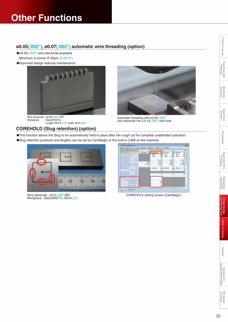
COREHOLD (Slug retention) (option)●This function allows the Slug to be automatically held in place after the rough cut for complete unattended operation
●Slug retention positions and lengths can be set by CamMagic or the built-in CAM on the machine
Wire electrode : ø0.2(.008")/BSWorkpiece : Steel(SKD11), t5mm(.2")
COREHOLD setting screen (CamMagic)
Wire electrode : ø0.05(.002")/SPWorkpiece : Steel(PD613), Length 20mm(.79") width 2mm(.08")
Automatic threading with ø0.05(.002") wire electrode into a 0.15(.006”) start hole
ø0.05(.002"), ø0.07(.003") automatic wire threading (option)●ø0.05(.002") wire electrode available
Minimum in-corner R 30µm (0.0012”)
●Improved design reduces maintenance
19 20
Long Life SystemEnergy Savings, Low Running Cost Other Functions
New energy-saving mode (Sleep Mode)
●The new energy-saving mode can be scheduled according to the current job ending time and start time the next day
●In Sleep Mode, the amount of energy consumed is greatly reduced as the result of using an automated pump-shut-off system
●Once the scheduled start time is reached, the system restarts the fluid system thermally, stabilizing the machine for work the next day
EDM work
22:00End of work
[Fluid system shut-down time]
6:00Wake-up
[Fluid system start-up time]
8:00Start of work
EDM workSleep Mode Recovery Temperatureadjustment
Saves electricity by supplying only the minimum required amount of power
Supplies power and supplies dielectric fluid to the bottom of the table
Supplies dielectric fluid to the bottom of the table
Temperature adjusted so machine can be used immediately
*Compared to conventional Mitsubishi Electric Wire-cut EDM (FA Series), compared to the same machining amounts
Running cost●Total running cost reduced up to 38%, which is
accounted for 90% by filter, ion exchange resin and power consumption
Power consumption reduced up to 69%
Wire electrode : ø0.2(.008")/BSWorkpiece : Steel(SKD11), t60mm(2.4")Surface roughness : Rz3.5µm/Ra0.45µm/18µ"Ra
Conventionalmodel
200 40 60 80 100(%)
MP ,Reduced 69%,Reduced 69%
0 20 40 60 80 100[%]
Compared to conventional Mitsubishi Electric Wire-cut EDM (FA Series)
Conventionalmodel
Wire electrode Filter Ion exchange resin Power consumption
MP
Others
Reduced 38%
× ×
Power consumption reduced by ODS
Filter cost reduced up to 45%
Conventionalmodel
200 40 60 80 100(%)
MP ,Reduced 45%,Reduced 45%
Wire consumption reduced up to 46%
Conventionalmodel
200 40 60 80 100(%)
MP ,Reduced 46%,Reduced 46%
Increased power-supply efficiency reduces the wearon the wire allowing the wire spooling rate to bereduced by PFC
●Filter cost is reduced by changing the filtration flow rate between the rough cut and finishing processes
COREHOLD (Slug retention) (option)●This function allows the Slug to be automatically held in place after the rough cut for complete unattended operation
●Slug retention positions and lengths can be set by CamMagic or the built-in CAM on the machine
Wire electrode : ø0.2(.008")/BSWorkpiece : Steel(SKD11), t5mm(.2")
COREHOLD setting screen (CamMagic)
Wire electrode : ø0.05(.002")/SPWorkpiece : Steel(PD613), Length 20mm(.79") width 2mm(.08")
Automatic threading with ø0.05(.002") wire electrode into a 0.15(.006”) start hole
ø0.05(.002"), ø0.07(.003") automatic wire threading (option)●ø0.05(.002") wire electrode available
Minimum in-corner R 30µm (0.0012”)
●Improved design reduces maintenance
19 20
Other F
unctionsO
ptionsW
orkability / O
perabilityA
utomatic W
ire T
hreadingP
roductivityM
achining A
ccuracyF
unctions and F
eaturesP
roduct Line-upFA
-related P
roductsM
achining C
ontrolPower Supply, Control
Specifications/Machine InstallationE
nergy Savings,
Low R
unning Cost
Other F
unctionsE
nergy Savings,
Low R
unning Cost
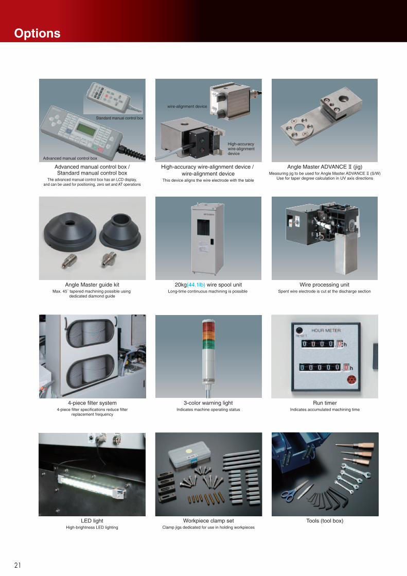
Options
20kg(44.1lb) wire spool unitLong-time continuous machining is possible
3-color warning lightIndicates machine operating status
Wire processing unitSpent wire electrode is cut at the discharge section
4-piece filter system4-piece filter specifications reduce filter
replacement frequency
Angle Master guide kitMax. 45˚ tapered machining possible using
dedicated diamond guide
Advanced manual control box /Standard manual control box
The advanced manual control box has an LCD display,and can be used for positioning, zero set and AT operations
Workpiece clamp setClamp jigs dedicated for use in holding workpieces
Run timerIndicates accumulated machining time
Standard manual control box
Advanced manual control box
Tools (tool box)LED lightHigh-brightness LED lighting
Angle Master ADVANCE (jig)Measuring jig to be used for Angle Master ADVANCE (S/W)
Use for taper degree calculation in UV axis directions
High-accuracy wire-alignment device / wire-alignment device
This device aligns the wire electrode with the table
High-accuracy wire-alignment device
wire-alignment device
* Please contact a Mitsubishi Electric representative for details.
<Personal computer><Schedule software>
<Process creation software>
<Coordinate measuring machine> <Robot + WEDM>
DNC
Wire-cut EDM automation system• Accumulates workpiece measurement data· Compatible for external set-up using a coordinate
measuring machine· Enables automatic measurement when measuring on an
EDM
• Creates processes offline
• Automatically exchanges workpieces using a robot
Network connection specifications (DNC, FTP Options)
Use EDM’s Explorer and receive data in the common HDD on the EDM side.After that, data I/O operations are required.
Operate on the EDM side and receive data from personal computer.
Operate on the personal computer side and send data to the EDM.
Operate on the personal computer side and send data directly to the EDM's NC data area.
The personal computer’s Explorer and the EDM’s common HDD are used. After that, data I/O operations are required for the EDM.
Commercially available DNC software must be installed on the personal computer side.Refer to DNC specifications operation for details.
Data transmission
Data transmission
Data transmissionLAN/W
(standard)
LAN/W(standard)
DNC
Data transmissionOperate on the EDM side and send data directly to the EDM's NC data area.
Data can be received only using data I/O operation.FTP
Data, such as NC programs, machining conditions and variables can be exchanged between a personal computer and EDM.The required options differ according to the models and purpose, and can be confirmed using the following table.One IP address must be prepared for each EDM within the user’s in-house network.
Required specifications Image drawing SupplementRequired option
21 22
Options and retrofit specifications differ according to country and region; please contact a Mitsubishi Electric representative for details. : Standard equipment : Can be retrofitted : Factory installation only : Not available
Option name MP1200 MP2400
Machine unit
UV OPT-drive system specificationsø0.05 (.002"), ø0.07 (.003") automatic wire threading*1
Wire processing unit *1
20kg (44.1lb) wire spool unitAdvanced manual control box (with axis display)
Power supply Ultrafine finish power supply (Super-DFS power supply)
Dielectric fluidsystem
Ion exchange resin 10L (0.35cu.ft.) specifications (Organo)Ion exchange resin 20L (0.70cu.ft.) specifications (Organo)4-piece filter system
Communications
External signal output*3
LAN/W*4
DNCFTP
Taper machining
Angle Master guide kit ø0.2 (.008") (±30°) *5 Angle Master guide kit ø0.2 (.008") (±45°) *5 Angle Master guide kit ø0.25 (.01") (±30°) *5
Angle Master guide kit ø0.25 (.01") (±45°) *5
Angle Master (S/W) *5
Angle Master ADVANCE2 (S/W) *2
Angle Master ADVANCE2 (measuring jig) *2
SoftwareAnti-virus protectionSleep modeCOREHOLD
Display3-color warning light*3
Run timer*3
Option box*6
Others
Instruction manual (paper edition)LED lightWire-alignment deviceHigh-accuracy wire-alignment deviceTools (tool box)Workpiece clamp set
*1 The ø0.05 (.002") to ø0.15 (.006") wire electrodes cannot be used with the wire processing unit. (These sizes can be used with the continuous wire feeder after removing the wire processing unit.)
*2 Angle Master ADVANCE2 (measuring jig) is needed for using Angle Master ADVANCE2 (S/W). *3 Option box is needed*4 LAN cable should be all straight wiring type with shielding connector, category 5 (100BASE-TX compliant), STP (four shielded twist pair). A switchable hub that can ground the shielded LAN cable should be used.*5 Standard diamond guide and nozzle (ø7(.28")) is used for taper machining of 15 degrees or less. Angle Master guide kit (H/W) is needed for taper machining of 15 degrees or more (wire electrode for taper machining should be used).*6 Necessary for mounting external signal output, 3-color warning light and run timer.
Other F
unctionsO
ptionsW
orkability / O
perabilityA
utomatic W
ire T
hreadingP
roductivityM
achining A
ccuracyF
unctions and F
eaturesP
roduct Line-upFA
-related P
roductsM
achining C
ontrolPower Supply, Control
Specifications/Machine InstallationE
nergy Savings,
Low R
unning Cost
Options

Power Supply, Control Specifications/Machine Installation
�Control unit functions
�Power supply/Control unit specifications
Year, month, date display
Overlap window function
Character string replacement function
Geometric function
Floating decimal point function
Control command
Corner R
Corner chamfer
Linear angle command
30-sec. short-circuit stop
Simultaneous 2-axis wire alignment
Workpiece inclination compensation
Reference block
Single block
Dry run
Automatic return
User macro
Automatic positioning (hole center, edge)
Automatic zero point return
Machining start hole return
Memory operation 1GB
Program edit
Coordinate rotation (K)
Pattern rotation (S)
Program no. designation
Expanded AT function
Graphics (drawing monitor)
Graphics (program check)
Graphics (automatic machining shape drawing)
Graphics (surface display)
Offset
Coordinate reading
Time reading
XY-axis independent scaling
Axis rotation (AR)
Automatic 2nd cut
Machining condition search
Block delete
USB flash memory
e-manual (electronic instruction manual)
Repeated positioning
Automatic power failure recovery
Workpiece coordinate system (106 items)
PM control
SL control
3D graphic check
Workpiece alignment
Axis exchange
Mirror image
Circumference calculation
Backlash compensation
Pitch error compensation
Soft limit (inside/outside prohibit)
Wire consumption estimate
CM3 control
OM control
3D viewer (Parasolid data display)
Sleep mode (MV-R)
Maintenance check
Automatic taper degree calculation
Status recording
Data variable operation
Alarm display
Machining time estimate
Built-in 2D-CAD/CAM
Built-in 3D-CAM
EM control
3D model compatible PM control (3D-PM)
Digital-AE@
Control unit specifications
Compatible model
Power supply unit specifications
Pow
er s
uppl
y un
itC
ontr
ol u
nit
Regenerative transistor pulse typeCompletely sealed/Indirect cooling
All modes50A
9 types : Anti-electrolysis power supply16 types44 types36 types10 types20 types 7 types 5 types 2 types
3 notches (changeable with M code or screen)• Workpiece material: Steel, tungsten, copper, aluminum
• Applicable only for rough-cut conditions
Built-in600 × 650 × 1767 (23.6 × 25.6 × 69.6)
240 (529)
ModelPower supply circuitCooling methodAnti-electrolytic power supplyMaximum output currentPower supply modeMachine voltage selectionMachining settingOFF timeStabilization circuit AStabilization circuit BStabilization circuit CStabilization circuit EFM circuit (LA, LC)
PM control
AVRUnit dimensions (mm) (in)Unit weight (kg) (lb)
W31MP-2Keyboard, USB flash memory, Ethernet
Touch panel, mouse15" color TFT
Alphanumeric charactersCNC closed loop
Max. 4 axes simultaneouslyX, Y, U, V, Z … 1/0.1µm
50nm (0.000050mm (0.000002"))±99999.999mm
Combined use of increment/absolute valuesLinear, circular, and spiral
0.00001 ~ 99.999999 (G code) 0.001 ~ 9999.999 (S code)Automatic selection of machining speed according to gap voltage sensing
Reverse path retrace during short-circuit±99999.999mm Offset numbers: 1 to 900 (intersection point calculation)
5 types (file, setup, machining support, monitor, maintenance)Interactive screen method
1 to 69991 to 99999999
Nesting level 301 to 99999
Input on screenHigh-speed, medium-speed, low-speed, ultra-slow speed, inching (0.0001mm/0.0005mm/0.0001mm) Positioning function, AT functionXY plane, XY-XZ plane, solid, table scaling, 3D model display, background drawing, automatic machining path drawing
1GBManagement of consumable parts (time display)
SL, CM, EM, OM, PM, BM494 × 175 × 346 (19.4 × 6.9 × 13.6) (excluding keyboard and mouse pad)
20 (44)
ModelNC program input methodPointing deviceDisplayDisplay charactersControl methodNumber of control axesSetting unitMinimum driving unit (mm) (in)Max. command valuePosition command formatInterpolation functionScale magnificationOptimum feed controlPath-retrace controlWire offsetBasic screen menuAutomatic 2nd cutMachining condition (E-pack) storageProgram number commandSub-programSequence numbersManual input positioningManual operation boxGraphicsUser memory capacityMaintenance functionAdaptive controlExternal dimensions (mm) (in)Weight (kg) (lb)
W31 (ADVANCE control unit) control unit functions
* Air (compressed air) is used to operate the automatic wire feeder and work tank door, etc. Air supplied from a normal compressor contains various impurities that could cause operation faults if they get into the pneumatic devices such as the solenoid valve. Install an air filter with a drainage discharge mechanism, etc., in the air source (primary source) piping to prevent impurities from entering the pneumatic devices.
Machine installation checklistDetermining the machining details
Installation conditions
1) Determine the workpiece2) Determine the machining site3) Determine the pre-processing site4) Determine the post-processing site
Confirmation of foundation and power-supply workIf there is any possibility of radio disturbance, investigate it prior to starting work.
1) Confirmation of floor area2) Confirmation of environment (constant-temperature dust-proof room, measure for radio disturbance, prevention of external noise)3) Confirmation of foundation floor4) Foundation work5) Primary wiring for power lead-in6) Grounding work7) Construction of dielectric fluid (city water) supply/drainage facilities8) Air piping work
Confirmation of delivery path
1) Traffic restrictions to factoryRoad widthEntry road
2) Factory entrance and width of gate in factory (m)Factory building entrance dimensions (height × width) (m)
3) Constant-temperature dust-proof room entrance dimensions (height × width) (m)
Preparation of installation fixtures1) Plan the installation fixtures2) Prepare or manufacture the fixtures
Training of programmers and operators1) Select the programmers and operators2) Apply for training seminars
Preparation of consumable parts1) Purchase consumable parts such as wire electrodes
CautionsThe standard delivery entrance dimensions for standard shipment delivery are given on the product line-up page. If the entrance is smaller than the standard delivery entrance, a machine with different dimensions can be shipped. * Please contact a Mitsubishi Electric representative for details (a separate estimate will be issued).Note that delivery may not be possible in some cases depending on the dimensions.
Precautions for selecting earth-leakage breakerTo prevent malfunctions caused by the external noise from control units, etc., a filter is installed for the power-supply input. By grounding one end of this filter, an earth-leakage current of approx. 30 to 40mA passes through the filter. A highly sensitive earth-leakage breaker (sensitivity current 30mA) could malfunction. Thus, a medium-sensitivity earth-leakage breaker (sensitivity current 100 to 200mA) is recommended for the wire-cut EDM. Class C grounding (grounding resistance of 10Ω or less) is recommended for the wire-cut EDM. Even if the sensitivity current is 200mA, the contact voltage will be 2V or less, and no problems will occur in preventing electric shock (application of tolerable contact current Class 2, 25V or less).
Harmonic distortionIf there is harmonic distortion in the power supply, the machine operation could be affected even if the voltage does not fluctuate. In addition, the harmonic current could flow from the wire-cut EDM to the power system and adversely affect peripheral devices. If the effect of the harmonic distortion causes problems, install a harmonic suppression filter or take other measures.
Terms of warrantyaTerms of warrantyThis will differ according to country and region of sale; please contact a Mitsubishi Electric representative for details.
sCoverageParts labor and travel are included free of charge when the failure occurs during normal use for the stated Terms of the warranty (based on proper usage and maintenance as described in the operations manual and sales agreement).Coverage exceptions:qWhen a failure occurs that was caused by a machine modification that directly affects the
machine’s functioning or accuracy. wWhen a failure occurs caused by the use of non-standard parts, consumables or lubricants. eWhen a failure occurs caused by a natural disaster such as lighting, earthquake or storms
and flooding. rWhen the use of non-recommended consumables or aftermarket parts are used such as
filters or flushing nozzles.
Please be aware that any workpiece/property damage and operation loss which may be associated with any fault of our machine are not covered by this warranty.
dPost Warranty / Expected Service LifeAfter the warranty period expires, all standard service rates and travel expenses will apply. Normal service life expectancy is 11 years after installation, but there may be some cases where discontinued electrical parts such as semiconductors and motors will reduce this period.
DisposalThe dielectric fluid, dielectric fluid filter, ion exchange resin, wire, etc., are industrial waste. These must be disposed of following national and local laws and ordinances.
1. Installation siteqConstant-temperature dust-proof room
· Recommended room temperature 20±1°C (68°F±2)· Usable temperature range 5 to 35°C (41°F to 95°F)
Temperature fluctuation will directly affect machine accuracy. To maintain performance accuracy, select a place with minimal temperature fluctuation.Install the EDM in a constant-temperature room when performing high precision machining, even when using skim cuts.Note that an environment where the temperature fluctuates by 3°C (5°F) or more within 24 hours, or 1°C (2°F) or more within one hour can adversely affect machining accuracy. Make sure that the machine body is not subject to direct wind from air-conditioners or to direct sunlight.
· Dust-free location is recommended.Install a wire-cut EDM in an environment with no corrosive gases, such as acid or salt, or mist, and with low levels of dust.Grinding dust can adversely affect the machine's linear scales and ball screws. Pay special attention to installation location to avoid this hazard (separate from grinding machine, or install in separate room, etc.).
· Humidity Within 30 to 75%RH (with no dew condensation).· Temperature range during transportation and storage
-25 to 55°C (-13°F to 131°F) (when power is not connected).wTolerable vibration of floor
· Select a floor where vibration or impact will not be conveyed.· As a reference, the vibration level should have a max. amplitude of 2µm or less at a 10 to
20Hz frequency.* Consult with the contractor or vibration measuring instrument manufacturer for details on
the measuring method.eFoundation
· The floor should be concrete with a thickness of 400mm (15.7") or more so it can sufficiently withstand the system’s weight.
· The floor inclination (step) must be within 6/1000 (floor inclination 6mm per 1m) (MP2400 Series).
2. Machining heating valueUse the equipment capacity to calculate the wire-cut EDM's heating value required for designing a constant-temperature room.
The above value is a guideline. Consult with the constant-temperature room manufacturer for details.
3. Power-supply equipment• Primary wiring 3-phase 200/220VAC±10% 60Hz, 3-phase 200VAC±10% 50Hz• Power capacity 10.0kVA (during normal use) (when using Ø0.2(.008")mm wire electrode)
13.5kVA (when using the maximum)* Use a 14mm2 or thicker cable for the primary connection.
4. Grounding workWire-cut EDMs must always be grounded to prevent external noise, radio disturbance and earth leakage.Install a wire-cut EDM in an environment with no corrosive gases, such as acid or salt, or mist, and with low levels of dust.
· Common grounding can be used if noise from other devices will not enter through the common grounding; the grounding cable must be connected independently to the grounding location (Fig. 2).
· Use a 14mm2 grounding wire.
5. Primary air equipment• Hose diameter : 1/4 hose (hose sleeve outer diameter: ø9.0 (0.35"))• Pressure : 0.5 to 0.7MPa (72.5 to 101.5psi)• Flow rate : 75R/min or more (2.65cu.ft./min.)
6. Shield roomInstall a shield room if a wire-cut EDM affects televisions or other communication facilities in the area. Observe the following points when installing the wire-cut EDM in the shield room.
1. Ground the wire-cut EDM in the shield room (Fig. 3).2. If the wire-cut EDM cannot be grounded in the shield room, connect the wire-cut EDM's
grounding cable to the shield room's grounding terminal (through bolt) as shown in Fig. 4.3. Consult with a Mitsubishi Electric representative for details on installing a shield room.
Shield room
Machinebody
Power-supplyunit
Shield room
Throughbolt
Within 1m
Machinebody
Power-supplyunit
Fig. 3 Fig. 4
Power-supply unit
Machine body RSTE
Power-supply unit
Machine body
Grounding cable for other device
RSTE
Fig. 1 Fig. 2
Check each item, and make sure that no item or order is overlooked.
Check the path inside and outside the factory to avoid any trouble during delivery.
Wire electrodes
*The wire electrodes shown above do not guarantee performance
OB-PN (ø0.1/BS ~ ø0.3/BS)
HBZ-U(N) (ø0.1/BS ~ ø0.3/BS)
SBS-HN (ø0.1/BS ~ ø0.3/BS)
SWP-SP (ø0.05/SP ~ ø0.07/SP)
Oki Electric Cable
Hitachi cable
Sumiden Fine Conductors
Suzuki Metal Industry
Use the following wire electrodes
Recommended sliding surface lubricants
Manufacturer
Exxon Mobil
Idemitsu Kosan
Showa Shell
JX Nippon Oil & Energy Corporation
Product name
Mobil DTE26
Super Hydro 68A
Terrace Oil 68
Super Mulpas DX68
Use one of the following lubricants for sliding surface As of March 2014
WMP
Heating value (kW) = Equipment capacity (kVA) x 0.6 = 13.5kVA x 0.6 = 8.1kW
MP1200 MP2400
23 24

Other F
unctionsO
ptionsW
orkability / O
perabilityA
utomatic W
ire T
hreadingP
roductivityM
achining A
ccuracyF
unctions and F
eaturesP
roduct Line-upFA
-related P
roductsM
achining C
ontrolPower Supply, Control
Specifications/Machine InstallationE
nergy Savings,
Low R
unning Cost
Power Supply, Control Specifications/Machine Installation
Power Supply, Control Specifications/Machine Installation
�Control unit functions
�Power supply/Control unit specifications
Year, month, date display
Overlap window function
Character string replacement function
Geometric function
Floating decimal point function
Control command
Corner R
Corner chamfer
Linear angle command
30-sec. short-circuit stop
Simultaneous 2-axis wire alignment
Workpiece inclination compensation
Reference block
Single block
Dry run
Automatic return
User macro
Automatic positioning (hole center, edge)
Automatic zero point return
Machining start hole return
Memory operation 1GB
Program edit
Coordinate rotation (K)
Pattern rotation (S)
Program no. designation
Expanded AT function
Graphics (drawing monitor)
Graphics (program check)
Graphics (automatic machining shape drawing)
Graphics (surface display)
Offset
Coordinate reading
Time reading
XY-axis independent scaling
Axis rotation (AR)
Automatic 2nd cut
Machining condition search
Block delete
USB flash memory
e-manual (electronic instruction manual)
Repeated positioning
Automatic power failure recovery
Workpiece coordinate system (106 items)
PM control
SL control
3D graphic check
Workpiece alignment
Axis exchange
Mirror image
Circumference calculation
Backlash compensation
Pitch error compensation
Soft limit (inside/outside prohibit)
Wire consumption estimate
CM3 control
OM control
3D viewer (Parasolid data display)
Sleep mode (MV-R)
Maintenance check
Automatic taper degree calculation
Status recording
Data variable operation
Alarm display
Machining time estimate
Built-in 2D-CAD/CAM
Built-in 3D-CAM
EM control
3D model compatible PM control (3D-PM)
Digital-AE@
Control unit specifications
Compatible model
Power supply unit specifications
Pow
er s
uppl
y un
itC
ontr
ol u
nit
Regenerative transistor pulse typeCompletely sealed/Indirect cooling
All modes50A
9 types : Anti-electrolysis power supply16 types44 types36 types10 types20 types 7 types 5 types 2 types
3 notches (changeable with M code or screen)• Workpiece material: Steel, tungsten, copper, aluminum
• Applicable only for rough-cut conditions
Built-in600 × 650 × 1767 (23.6 × 25.6 × 69.6)
240 (529)
ModelPower supply circuitCooling methodAnti-electrolytic power supplyMaximum output currentPower supply modeMachine voltage selectionMachining settingOFF timeStabilization circuit AStabilization circuit BStabilization circuit CStabilization circuit EFM circuit (LA, LC)
PM control
AVRUnit dimensions (mm) (in)Unit weight (kg) (lb)
W31MP-2Keyboard, USB flash memory, Ethernet
Touch panel, mouse15" color TFT
Alphanumeric charactersCNC closed loop
Max. 4 axes simultaneouslyX, Y, U, V, Z … 1/0.1µm
50nm (0.000050mm (0.000002"))±99999.999mm
Combined use of increment/absolute valuesLinear, circular, and spiral
0.00001 ~ 99.999999 (G code) 0.001 ~ 9999.999 (S code)Automatic selection of machining speed according to gap voltage sensing
Reverse path retrace during short-circuit±99999.999mm Offset numbers: 1 to 900 (intersection point calculation)
5 types (file, setup, machining support, monitor, maintenance)Interactive screen method
1 to 69991 to 99999999
Nesting level 301 to 99999
Input on screenHigh-speed, medium-speed, low-speed, ultra-slow speed, inching (0.0001mm/0.0005mm/0.0001mm) Positioning function, AT functionXY plane, XY-XZ plane, solid, table scaling, 3D model display, background drawing, automatic machining path drawing
1GBManagement of consumable parts (time display)
SL, CM, EM, OM, PM, BM494 × 175 × 346 (19.4 × 6.9 × 13.6) (excluding keyboard and mouse pad)
20 (44)
ModelNC program input methodPointing deviceDisplayDisplay charactersControl methodNumber of control axesSetting unitMinimum driving unit (mm) (in)Max. command valuePosition command formatInterpolation functionScale magnificationOptimum feed controlPath-retrace controlWire offsetBasic screen menuAutomatic 2nd cutMachining condition (E-pack) storageProgram number commandSub-programSequence numbersManual input positioningManual operation boxGraphicsUser memory capacityMaintenance functionAdaptive controlExternal dimensions (mm) (in)Weight (kg) (lb)
W31 (ADVANCE control unit) control unit functions
* Air (compressed air) is used to operate the automatic wire feeder and work tank door, etc. Air supplied from a normal compressor contains various impurities that could cause operation faults if they get into the pneumatic devices such as the solenoid valve. Install an air filter with a drainage discharge mechanism, etc., in the air source (primary source) piping to prevent impurities from entering the pneumatic devices.
Machine installation checklistDetermining the machining details
Installation conditions
1) Determine the workpiece2) Determine the machining site3) Determine the pre-processing site4) Determine the post-processing site
Confirmation of foundation and power-supply workIf there is any possibility of radio disturbance, investigate it prior to starting work.
1) Confirmation of floor area2) Confirmation of environment (constant-temperature dust-proof room, measure for radio disturbance, prevention of external noise)3) Confirmation of foundation floor4) Foundation work5) Primary wiring for power lead-in6) Grounding work7) Construction of dielectric fluid (city water) supply/drainage facilities8) Air piping work
Confirmation of delivery path
1) Traffic restrictions to factoryRoad widthEntry road
2) Factory entrance and width of gate in factory (m)Factory building entrance dimensions (height × width) (m)
3) Constant-temperature dust-proof room entrance dimensions (height × width) (m)
Preparation of installation fixtures1) Plan the installation fixtures2) Prepare or manufacture the fixtures
Training of programmers and operators1) Select the programmers and operators2) Apply for training seminars
Preparation of consumable parts1) Purchase consumable parts such as wire electrodes
CautionsThe standard delivery entrance dimensions for standard shipment delivery are given on the product line-up page. If the entrance is smaller than the standard delivery entrance, a machine with different dimensions can be shipped. * Please contact a Mitsubishi Electric representative for details (a separate estimate will be issued).Note that delivery may not be possible in some cases depending on the dimensions.
Precautions for selecting earth-leakage breakerTo prevent malfunctions caused by the external noise from control units, etc., a filter is installed for the power-supply input. By grounding one end of this filter, an earth-leakage current of approx. 30 to 40mA passes through the filter. A highly sensitive earth-leakage breaker (sensitivity current 30mA) could malfunction. Thus, a medium-sensitivity earth-leakage breaker (sensitivity current 100 to 200mA) is recommended for the wire-cut EDM. Class C grounding (grounding resistance of 10Ω or less) is recommended for the wire-cut EDM. Even if the sensitivity current is 200mA, the contact voltage will be 2V or less, and no problems will occur in preventing electric shock (application of tolerable contact current Class 2, 25V or less).
Harmonic distortionIf there is harmonic distortion in the power supply, the machine operation could be affected even if the voltage does not fluctuate. In addition, the harmonic current could flow from the wire-cut EDM to the power system and adversely affect peripheral devices. If the effect of the harmonic distortion causes problems, install a harmonic suppression filter or take other measures.
Terms of warrantyaTerms of warrantyThis will differ according to country and region of sale; please contact a Mitsubishi Electric representative for details.
sCoverageParts labor and travel are included free of charge when the failure occurs during normal use for the stated Terms of the warranty (based on proper usage and maintenance as described in the operations manual and sales agreement).Coverage exceptions:qWhen a failure occurs that was caused by a machine modification that directly affects the
machine’s functioning or accuracy. wWhen a failure occurs caused by the use of non-standard parts, consumables or lubricants. eWhen a failure occurs caused by a natural disaster such as lighting, earthquake or storms
and flooding. rWhen the use of non-recommended consumables or aftermarket parts are used such as
filters or flushing nozzles.
Please be aware that any workpiece/property damage and operation loss which may be associated with any fault of our machine are not covered by this warranty.
dPost Warranty / Expected Service LifeAfter the warranty period expires, all standard service rates and travel expenses will apply. Normal service life expectancy is 11 years after installation, but there may be some cases where discontinued electrical parts such as semiconductors and motors will reduce this period.
DisposalThe dielectric fluid, dielectric fluid filter, ion exchange resin, wire, etc., are industrial waste. These must be disposed of following national and local laws and ordinances.
1. Installation siteqConstant-temperature dust-proof room
· Recommended room temperature 20±1°C (68°F±2)· Usable temperature range 5 to 35°C (41°F to 95°F)
Temperature fluctuation will directly affect machine accuracy. To maintain performance accuracy, select a place with minimal temperature fluctuation.Install the EDM in a constant-temperature room when performing high precision machining, even when using skim cuts.Note that an environment where the temperature fluctuates by 3°C (5°F) or more within 24 hours, or 1°C (2°F) or more within one hour can adversely affect machining accuracy. Make sure that the machine body is not subject to direct wind from air-conditioners or to direct sunlight.
· Dust-free location is recommended.Install a wire-cut EDM in an environment with no corrosive gases, such as acid or salt, or mist, and with low levels of dust.Grinding dust can adversely affect the machine's linear scales and ball screws. Pay special attention to installation location to avoid this hazard (separate from grinding machine, or install in separate room, etc.).
· Humidity Within 30 to 75%RH (with no dew condensation).· Temperature range during transportation and storage
-25 to 55°C (-13°F to 131°F) (when power is not connected).wTolerable vibration of floor
· Select a floor where vibration or impact will not be conveyed.· As a reference, the vibration level should have a max. amplitude of 2µm or less at a 10 to
20Hz frequency.* Consult with the contractor or vibration measuring instrument manufacturer for details on
the measuring method.eFoundation
· The floor should be concrete with a thickness of 400mm (15.7") or more so it can sufficiently withstand the system’s weight.
· The floor inclination (step) must be within 6/1000 (floor inclination 6mm per 1m) (MP2400 Series).
2. Machining heating valueUse the equipment capacity to calculate the wire-cut EDM's heating value required for designing a constant-temperature room.
The above value is a guideline. Consult with the constant-temperature room manufacturer for details.
3. Power-supply equipment• Primary wiring 3-phase 200/220VAC±10% 60Hz, 3-phase 200VAC±10% 50Hz• Power capacity 10.0kVA (during normal use) (when using Ø0.2(.008")mm wire electrode)
13.5kVA (when using the maximum)* Use a 14mm2 or thicker cable for the primary connection.
4. Grounding workWire-cut EDMs must always be grounded to prevent external noise, radio disturbance and earth leakage.Install a wire-cut EDM in an environment with no corrosive gases, such as acid or salt, or mist, and with low levels of dust.
· Common grounding can be used if noise from other devices will not enter through the common grounding; the grounding cable must be connected independently to the grounding location (Fig. 2).
· Use a 14mm2 grounding wire.
5. Primary air equipment• Hose diameter : 1/4 hose (hose sleeve outer diameter: ø9.0 (0.35"))• Pressure : 0.5 to 0.7MPa (72.5 to 101.5psi)• Flow rate : 75R/min or more (2.65cu.ft./min.)
6. Shield roomInstall a shield room if a wire-cut EDM affects televisions or other communication facilities in the area. Observe the following points when installing the wire-cut EDM in the shield room.
1. Ground the wire-cut EDM in the shield room (Fig. 3).2. If the wire-cut EDM cannot be grounded in the shield room, connect the wire-cut EDM's
grounding cable to the shield room's grounding terminal (through bolt) as shown in Fig. 4.3. Consult with a Mitsubishi Electric representative for details on installing a shield room.
Shield room
Machinebody
Power-supplyunit
Shield room
Throughbolt
Within 1m
Machinebody
Power-supplyunit
Fig. 3 Fig. 4
Power-supply unit
Machine body RSTE
Power-supply unit
Machine body
Grounding cable for other device
RSTE
Fig. 1 Fig. 2
Check each item, and make sure that no item or order is overlooked.
Check the path inside and outside the factory to avoid any trouble during delivery.
Wire electrodes
*The wire electrodes shown above do not guarantee performance
OB-PN (ø0.1/BS ~ ø0.3/BS)
HBZ-U(N) (ø0.1/BS ~ ø0.3/BS)
SBS-HN (ø0.1/BS ~ ø0.3/BS)
SWP-SP (ø0.05/SP ~ ø0.07/SP)
Oki Electric Cable
Hitachi cable
Sumiden Fine Conductors
Suzuki Metal Industry
Use the following wire electrodes
Recommended sliding surface lubricants
Manufacturer
Exxon Mobil
Idemitsu Kosan
Showa Shell
JX Nippon Oil & Energy Corporation
Product name
Mobil DTE26
Super Hydro 68A
Terrace Oil 68
Super Mulpas DX68
Use one of the following lubricants for sliding surface As of March 2014
WMP
Heating value (kW) = Equipment capacity (kVA) x 0.6 = 13.5kVA x 0.6 = 8.1kW
MP1200 MP2400
23 24
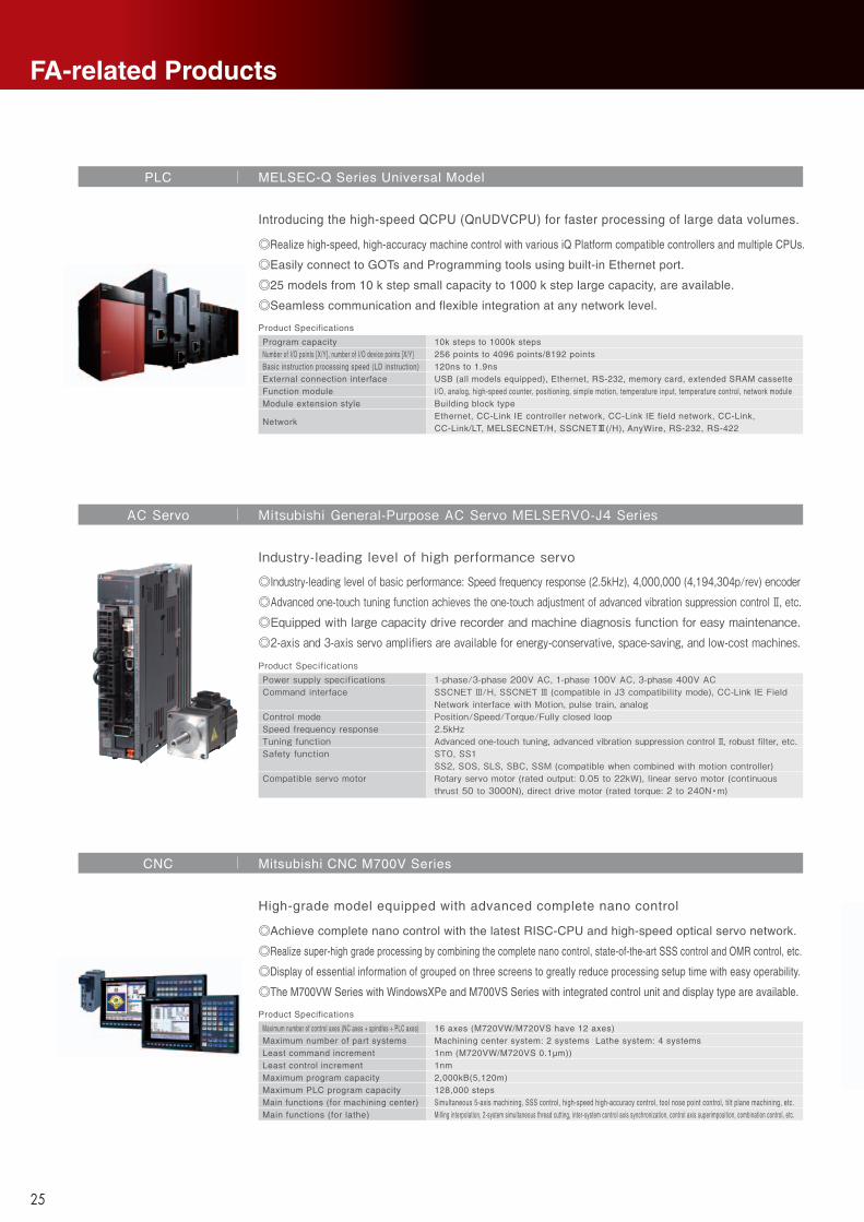
FA-related Products
Product Specifications
Degrees of freedom
Installation
Maximum load capacityMaximum reach radius
Vertical:6 Horizontal:4Vertical:Floor-mount, ceiling mount, wall mount (Range of motion for J1 is limited)Horizontal:Floor-mountVertical:2-20kg Horizontal:3-20kgVertical:504-1503mm Horizontal:350-1,000mm
Robot MELFA F Series
High speed, high precision and high reliability industrial robot
Product specifications
Model NameDrive systemStroke (X×Y×X) [mm]Rapid feedrate [m/min]Processing feedrate [m/min]Positioning accuracy [mm]Repeat accuracy [mm]Rated output [W]
ML3015eXFlying optic (3-axis beam movement)3100×1565×150X,Y axes: Max. 100; Z-axis: Max. 65Max. 500.05 / 500 (X,Y axes)± 0.01 (X,Y axes)4500
Laser Processing Machine CO2 2-Dimensional Laser Processing Machine eX-Series
A global standard CO2 2-dimensional laser processing systems.
Product specifications
Model nameProcessing workpiece dimensions [mm]XY table maximum feedrate [m/min]Laser typeOscillator power [W]Oscillator set pulse frequency
ML605GTW4(-H)-5350U/ML605GTW4(-P)-5350U/ML706GTW4-5350U620×560/815×66250CO2 laser360W10 to 10000Hz
Laser Processing Machine for Substrate Drilling GTW4 Series
Compact body and slim arm design, allowing operating area to be expanded and load capacity increased.
The fastest in its class using high performance motors and unique driver control technology.
Improved flexibility for robot layout design considerations.
Optimal motor control tuning set automatically based on operating position, posture, and load conditions.
Productivity has been dramatically enhanced owing to improved acceleration and the latest control technologies exclusive to Mitsubishi Electric.
2 Action Cutting allows for the entire process, from job setup to parts cutting, to be completed in two simple actions.
When not processing, the system switches to ECO mode and the resonator stops idling. Minimizes energy consumption, reducing running costs by up to 99%*1 during standby.
*1: Compared to the previous LV-Series with Mitsubishi's designated benchmark shape.
Newly-developed super-fast galvano and 360W high-power resonator achieve industry-leading productivity.
Laser beam generated by unparalleled resonator enables stable high-quality copper-direct processing on various surface treatments.
Single machine can support variety of processing application with Mitsubishi unique powerful laser and optimum beam control.
Original resonator structure, which can be refreshed by replacing some parts only, realizes low operating cost.
Ever-evolving global standard machine
Product Specifications
Maximum number of control axes (NC axes + spindles + PLC axes)Maximum number of part systemsLeast command incrementLeast control incrementMaximum program capacityMaximum PLC program capacityMain functions (for machining center)Main functions (for lathe)
16 axes (M720VW/M720VS have 12 axes)Machining center system: 2 systems Lathe system: 4 systems1nm (M720VW/M720VS 0.1µm))1nm2,000kB(5,120m)128,000 stepsSimultaneous 5-axis machining, SSS control, high-speed high-accuracy control, tool nose point control, tilt plane machining, etc.Milling interpolation, 2-system simultaneous thread cutting, inter-system control axis synchronization, control axis superimposition, combination control, etc.
CNC Mitsubishi CNC M700V Series
High-grade model equipped with advanced complete nano control
Product Specifications
Program capacityNumber of I/O points [X/Y], number of I/O device points [X/Y]Basic instruction processing speed (LD instruction)External connection interfaceFunction moduleModule extension style
Network
10k steps to 1000k steps256 points to 4096 points/8192 points120ns to 1.9nsUSB (all models equipped), Ethernet, RS-232, memory card, extended SRAM cassetteI/O, analog, high-speed counter, positioning, simple motion, temperature input, temperature control, network moduleBuilding block typeEthernet, CC-Link IE controller network, CC-Link IE field network, CC-Link,CC-Link/LT, MELSECNET/H, SSCNET#(/H), AnyWire, RS-232, RS-422
PLC MELSEC-Q Series Universal Model
Achieve complete nano control with the latest RISC-CPU and high-speed optical servo network.
Realize super-high grade processing by combining the complete nano control, state-of-the-art SSS control and OMR control, etc.
Display of essential information of grouped on three screens to greatly reduce processing setup time with easy operability.
The M700VW Series with WindowsXPe and M700VS Series with integrated control unit and display type are available.
Realize high-speed, high-accuracy machine control with various iQ Platform compatible controllers and multiple CPUs.
Easily connect to GOTs and Programming tools using built-in Ethernet port.
25 models from 10 k step small capacity to 1000 k step large capacity, are available.
Seamless communication and flexible integration at any network level.
Introducing the high-speed QCPU (QnUDVCPU) for faster processing of large data volumes.
Product SpecificationsPower supply specificationsCommand interface
Control modeSpeed frequency responseTuning functionSafety function
Compatible servo motor
1-phase/3-phase 200V AC, 1-phase 100V AC, 3-phase 400V ACSSCNET Ⅲ/H, SSCNET Ⅲ (compatible in J3 compatibility mode), CC-Link IE Field Network interface with Motion, pulse train, analogPosition/Speed/Torque/Fully closed loop2.5kHzAdvanced one-touch tuning, advanced vibration suppression control Ⅱ, robust filter, etc.STO, SS1SS2, SOS, SLS, SBC, SSM (compatible when combined with motion controller)Rotary servo motor (rated output: 0.05 to 22kW), linear servo motor (continuous thrust 50 to 3000N), direct drive motor (rated torque: 2 to 240N •m)
AC Servo Mitsubishi General-Purpose AC Servo MELSERVO-J4 Series
Industry-leading level of high performance servo
◎Industry-leading level of basic performance: Speed frequency response (2.5kHz), 4,000,000 (4,194,304p/rev) encoder◎Advanced one-touch tuning function achieves the one-touch adjustment of advanced vibration suppression control Ⅱ, etc. ◎Equipped with large capacity drive recorder and machine diagnosis function for easy maintenance.◎2-axis and 3-axis servo amplifiers are available for energy-conservative, space-saving, and low-cost machines.
25 26
Other F
unctionsO
ptionsW
orkability / O
perabilityA
utomatic W
ire T
hreadingP
roductivityM
achining A
ccuracyF
unctions and F
eaturesP
roduct Line-upFA
-related P
roductsM
achining C
ontrolPower Supply, Control
Specifications/Machine InstallationE
nergy Savings,
Low R
unning Cost
FA-related
Products

MP
Series
series
Wire-cut EDM SystemsMP Series
K-KL2-4-C0119-A NA1407 Printed in Japan oIPp
* Not all models are supported for all countries and regions.* Machine specifications differ according to the country and region, so please check with your dealer.* Processing data provided in this brochure is for reference only.
HEAD OFFICE: TOKYO BLDG., 2-7-3, MARUNOUCHI, CHIYODA-KU, TOKYO 100-8310, JAPANNAGOYA WORKS: 1-14, YADA-MINAMI, 5-CHOME, HIGASHI-KU, NAGOYA 461-8670, JAPAN
New publication, effective Jul. 2014.Specifications are subject to change without notice.
Mitsubishi Electric Corporation Nagoya Works is a factory certified for ISO14001 (standards for environmental management systems) and ISO9001(standards for quality assurance management systems)