Embed Size (px)
Citation preview

SERAPH A3SERAPH A3 MWX
User Manual

The SERAPH A3 conforms the following standards: EN 55022: 1998 + A1: 2000+ A2: 2003; class A; EN 55024: 1998 + A1: 2000 + A2: 2003; class A; n orderfor an installation of this product maintain compliance with the limits of a classA device, shielded audio cables must be used, not longer than 50 cm. Attention:This is a device of the class A and can cause interference to radio or televisionreception within the residential area. The user is encouraged to try to correct theinterference by suitable measures.
c© 15th February 2013, v1.0 MARIANHardware Design by MARIANAll rights reserved. No part of this User’s Guide may be reproduced or transmitted in any form or by any means,electronically or mechanically, including photocopy, translation, recording, or any information storage and retrieval system,without permission in writing from MARIAN. All trademarks are the property of the respective owners.MARIAN is not liable for any damage to the software, hardware and data and costs resulting from it, which are caused byimproper handling or installation of the hardware.Technical changes are reserved.
Contents
1 Welcome 1
2 Before you start ... 22.1 Features . . . . . . . . . . . . . . . . . . . . . . . . . . . . . . . . . . . . . . . . . 22.2 Installation . . . . . . . . . . . . . . . . . . . . . . . . . . . . . . . . . . . . . . . 2
2.2.1 Scope of Supply . . . . . . . . . . . . . . . . . . . . . . . . . . . . . . . . 22.2.2 System requirements . . . . . . . . . . . . . . . . . . . . . . . . . . . . . . 22.2.3 Hardware and software installation . . . . . . . . . . . . . . . . . . . . . . 32.2.4 Driver and firmware updates . . . . . . . . . . . . . . . . . . . . . . . . . 3
2.3 Anschlusse . . . . . . . . . . . . . . . . . . . . . . . . . . . . . . . . . . . . . . . . 4
3 Let’s start: Basics 63.1 Introduction . . . . . . . . . . . . . . . . . . . . . . . . . . . . . . . . . . . . . . . 63.2 The SERAPH A3 in connection with digital devices . . . . . . . . . . . . . . . . 6
3.2.1 Background . . . . . . . . . . . . . . . . . . . . . . . . . . . . . . . . . . . 63.2.2 What is a clock? . . . . . . . . . . . . . . . . . . . . . . . . . . . . . . . . 63.2.3 The rules of the digital audio world . . . . . . . . . . . . . . . . . . . . . 7
3.3 Example: The SERAPH A3 with 3 MARIAN ADCON . . . . . . . . . . . . . . . 7
4 Let’s start: Play 84.1 Introduction . . . . . . . . . . . . . . . . . . . . . . . . . . . . . . . . . . . . . . . 84.2 Using a media playback program . . . . . . . . . . . . . . . . . . . . . . . . . . . 84.3 Using an ASIO (multi-channel) music software . . . . . . . . . . . . . . . . . . . 84.4 Playback with the SERAPH A3 . . . . . . . . . . . . . . . . . . . . . . . . . . . . 94.5 Editing the Sound of Signals . . . . . . . . . . . . . . . . . . . . . . . . . . . . . 114.6 Setting up a separate stereo headphone mix for a musician . . . . . . . . . . . . . 114.7 Feeding an external effects device . . . . . . . . . . . . . . . . . . . . . . . . . . . 12
5 Let’s start: Recording 135.1 Introduction . . . . . . . . . . . . . . . . . . . . . . . . . . . . . . . . . . . . . . . 135.2 Using a media playback program . . . . . . . . . . . . . . . . . . . . . . . . . . . 135.3 Using an ASIO (multi-channel) music software . . . . . . . . . . . . . . . . . . . 135.4 Assignment in the SERAPH A3 routing . . . . . . . . . . . . . . . . . . . . . . . 14
6 The SERAPH A3 in Detail: Mixing and Routing 156.1 Introduction . . . . . . . . . . . . . . . . . . . . . . . . . . . . . . . . . . . . . . . 156.2 Operation of Mixer and Routing . . . . . . . . . . . . . . . . . . . . . . . . . . . 156.3 View options . . . . . . . . . . . . . . . . . . . . . . . . . . . . . . . . . . . . . . 166.4 Snapshots . . . . . . . . . . . . . . . . . . . . . . . . . . . . . . . . . . . . . . . . 176.5 Setups . . . . . . . . . . . . . . . . . . . . . . . . . . . . . . . . . . . . . . . . . . 176.6 The mixer in detail . . . . . . . . . . . . . . . . . . . . . . . . . . . . . . . . . . . 186.7 The routing in detail . . . . . . . . . . . . . . . . . . . . . . . . . . . . . . . . . . 21
7 The SERAPH A3 in Detail: System settings 227.1 Introduction . . . . . . . . . . . . . . . . . . . . . . . . . . . . . . . . . . . . . . . 227.2 Clock Status Panel . . . . . . . . . . . . . . . . . . . . . . . . . . . . . . . . . . . 237.3 Settings . . . . . . . . . . . . . . . . . . . . . . . . . . . . . . . . . . . . . . . . . 247.4 ASIO Device Setup . . . . . . . . . . . . . . . . . . . . . . . . . . . . . . . . . . . 27
8 The SERAPH A3 in Detail: TDM SyncBus 298.1 Principles of the TDM SyncBus . . . . . . . . . . . . . . . . . . . . . . . . . . . . 298.2 Examples the functionality of the TDM SyncBus . . . . . . . . . . . . . . . . . . 29
9 Appendix 319.1 Service and Support . . . . . . . . . . . . . . . . . . . . . . . . . . . . . . . . . . 319.2 Glossary . . . . . . . . . . . . . . . . . . . . . . . . . . . . . . . . . . . . . . . . . 329.3 Special Notes . . . . . . . . . . . . . . . . . . . . . . . . . . . . . . . . . . . . . . 34
9.3.1 Clock settings when using ASIO . . . . . . . . . . . . . . . . . . . . . . . 349.3.2 Samplerate on record/playback . . . . . . . . . . . . . . . . . . . . . . . . 349.3.3 Different samplerates on record/playback via ASIO . . . . . . . . . . . . . 349.3.4 Simultaneous playback on one device via ASIO . . . . . . . . . . . . . . . 34
10 Technical Facts 36
1 Welcome
1 Welcome
The MARIAN team proudly presents to you the SERAPH A3, thanking you for your confidence.A new abundance of functions while at the same time maintaining an intuitive handling - thesehigh expectations we try to meet in this product. In the SERAPH A3 you can see newesttechnologies merging with long proven experience and development skills into a powerful DAW(Digital Audio Workstation). What is there to discover?
Of course, poured in hardware, the new processing unit, with much affection called the’BEAST’. This newly-developed DSP mixer is nothing less than a full-fledged digital mixer withup to 64 channels, 8 mix sums and 256 EQs! Easily you create sub-mixes, that are perfect foreither headphone mixes or sending feeds to reverb units thanks to the pre/post switches. Foreach of the full-parametric EQs, modeled in accordance to analogue prototypes, you can freelydecide on which sub-mix it is to be effective. EQ on the main mix but not on the headphonemix or vice versa? With the mixer of the SERAPH A3 this is not a problem any more.
The special features of this system cannot only be found in a ’BEASTly power’, but also inits flexibility. This workhorse tows a separate routing matrix allowing to send any signal to anyoutput or back to the input again. This includes even the playback signals of a user-softwareand the sums of the DSP mixer, which can thus be easily re-recorded on the same computersystem or manipulated with the on-board EQs.
In a way this manual in your hand is kind of like a trainers whip to tame the fullness of thefunctions of the BEAST and to make them fit to your daily tasks in the studio. The chapterscalled ’Let’s start’ offer a quick introduction by explaining a simple playback and recordingprocess. But you can also get in-depth information in the chapters ’SERAPH A3 in detail’,explaining all functions in detail and their relationship to each other. Finally, at the end of thismanual, you can find a small glossary that will help you to explain unfamiliar terms.
And now we hope you’ll enjoy trying out and getting to know your SERAPH A3! We areconfident that this sound system in domesticated form will be a partner in the realization of allyour music projects for years to come.
Your MARIAN Team
1
2 Before you start ...
2 Before you start ...
2.1 FeaturesYour SERAPH A3 is equipped with many useful functions. Here is a list of the features andoptions:
3 PCIe card with 3 ADAT I/O (24 channels)
3 2 MIDI I/O (MWX version only)
3 WordClock I/O (MWX version only)
3 The BEAST
? 64 channel mixer, hardware-based, latency-free, 52 Bit? 256 high-precision analog-feel EQs (in each channel: 1x low shelf, 2x peak, 1x high
shelf)? flexible and extensive mix, monitor, and routing functions
3 Sample rates up to 96 kHz
3 S/MUX compatible
3 MARIAN SyncBus compatible and TDM SyncBus compatible
3 Synchronization as clock master (Internal clock to the ADAT outputs, SyncBus or theWordclock output )
3 Synchronization as clock slave (processing an external clock at the ADAT, Wordclock orSyncBus )
3 Fail-safe firmware update technology (automatic recovery of the firmware in case of errors)
3 Advanced multi-client drivers for WindowsTM32/64bit: 20001/XP/Vista/7 and Server2003/2008/2010and Mac OS X 10.4 to 10.7
3 Driver support: MME, ASIO 2.22, GSIF 2.0, WDM Audio, Direct- Sound and MME aswell as Core Audio (Mac OS X) 3
2.2 Installation
2.2.1 Scope of Supply
After carefully opening the package of the SERAPH A3, please be sure to check if the followingcomponents are to be found complete and undamaged:
3 1 x SERAPH A3 PCIe card
3 1 x MIDI/WordClock Extender with connector cable (MWX version only)
3 1 x cable for MIDI Input/output (MWX version only)
3 1 x CD-ROM with driver software and manual
3 Quick Start
2.2.2 System requirements
For the successful and correct operation of the SERAPH A3 your computer needs to meet thefollowing minimum requirements:
1only for 32bit WindowsTM
2On 32bit WindowsTMVersion: ASIO 2.13Please note, that the manual covers the explanation of WindowsTMspecific operation, only.
2
2 Before you start ...
3 PC: Intel Pentium or AMD processor with a clock frequency of 2 GHz and 1024 MB Ram;Operating System WindowsTM32/64bit: 20004/XP/Vista/7 and Server 2003/2008/2010;DirectX 9c
3 MAC: PowerPC ab G4, or Intel Prozessor with 1024MB Ram; Mac OS X 10.4 to 10.7
3 1 free expansion slots (one free PCIe slot)
3 A free slot for the MIDI/WordClock Extender (MWX version only)
Please note that the system requirements may be higher depending on the operating systemand audio application used.
2.2.3 Hardware and software installation
In the brochure labeled ”Quick Start” you will find all the installation steps as a graphical guide.If you still have any questions or in case that problems appear during the installation, pleasecontact our support service. You will find all the different ways to contact the support servicesin the appendix of this manual.
2.2.4 Driver and firmware updates
In some cases, there is a driver update available for the SERAPH A3 in the download sectionof the MARIAN homepage. It may include:
3 Functional improvements of the driver and/or the user interface (s)
3 Adjustments to new operating systems and/or their new components (updates and servicepacks)
3 Compatibility upgrades to audio applications and third-party applications
When performing a driver update please follow the instructions provided in the ’readme.htm’file, which is part of the packed folder of the new driver files5.
Important: In the course of a driver update it may become necessary for the firmware ofthe SERAPH A3 to be updated. Whether a firmware update is necessary or not, can onlybe determined after an installation/update was performed. The firmware upgrade will then beexecuted automatically and must finish with a reboot (Turn off and turn on) of the PC system.The Fail-safe firmware update technology MARIAN protects the SERAPH A3 against errors,which could occur due to the interruption of the update process, such as a power failure. Ifnormally this would result in a total malfunction of a system, the fail-safe technology ensuresthat at the next initialization of the SERAPH A3 a core firmware is loaded. Thus the soundcard may again be detected correctly by a WindowsTMsystem.
Please note: Following a successful firmware update and after the restart of the system,WindowsTM32/64bit: 20006/XP/Vista/7 and Server 2003/2008/2010will find a new hardware,because the hardware ID of the SERAPH A3 may have changed due to the former update. Asthe driver files are already installed, you must simply choose ”Install software automatically(recommended)” when the WindowsTMhardware wizard appears.
4only for 32bit WindowsTM
5Even if the WindowsTM Explorer is capable of displaying compressed files – for installing the driver (update)a full decompression is required!
6only for 32bit WindowsTM
3
2 Before you start ...
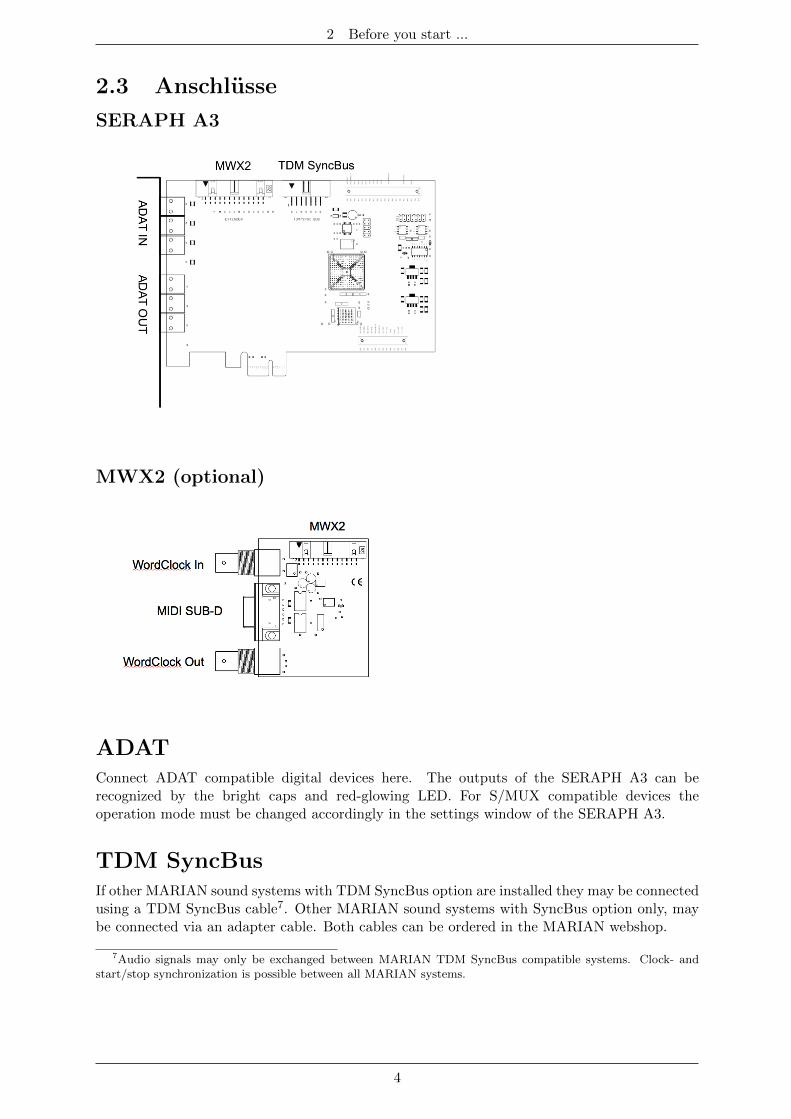
2.3 Anschlusse
SERAPH A3
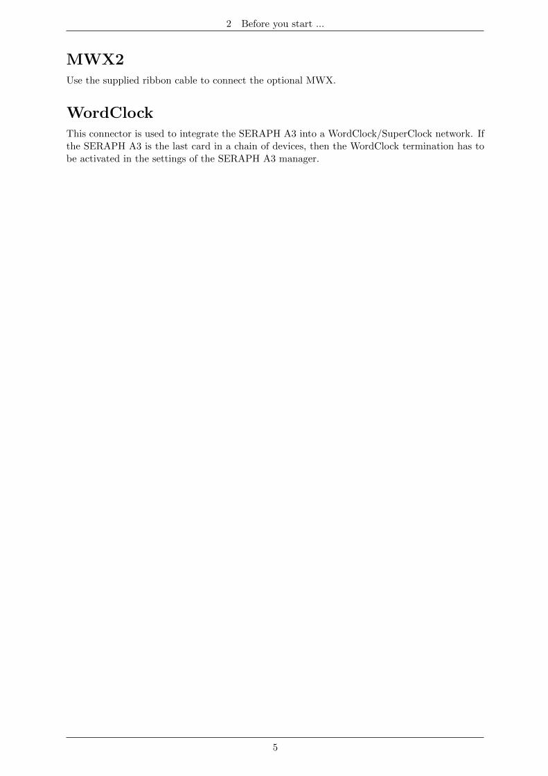
MWX2 (optional)
ADATConnect ADAT compatible digital devices here. The outputs of the SERAPH A3 can berecognized by the bright caps and red-glowing LED. For S/MUX compatible devices theoperation mode must be changed accordingly in the settings window of the SERAPH A3.
TDM SyncBusIf other MARIAN sound systems with TDM SyncBus option are installed they may be connectedusing a TDM SyncBus cable7. Other MARIAN sound systems with SyncBus option only, maybe connected via an adapter cable. Both cables can be ordered in the MARIAN webshop.
7Audio signals may only be exchanged between MARIAN TDM SyncBus compatible systems. Clock- andstart/stop synchronization is possible between all MARIAN systems.
4
2 Before you start ...
MWX2Use the supplied ribbon cable to connect the optional MWX.
WordClockThis connector is used to integrate the SERAPH A3 into a WordClock/SuperClock network. Ifthe SERAPH A3 is the last card in a chain of devices, then the WordClock termination has tobe activated in the settings of the SERAPH A3 manager.
5
3 Let’s start: Basics
3 Let’s start: Basics
In this chapter you will learn
3 The fundamentals of Digital Signal Processing,
3 To avoid problems/errors when connecting digital devices
3 To make the correct settings for the connection of 3 MARIAN ADCON
3.1 IntroductionThe SERAPH A3 sound system is a purely digital system. For connecting other devices thisbrings along some specialties. Basic rules (an output is connected to an input, and vice versa)certainly do need not be explained here again. For digital audio signals, however, the clock playsan important role. Following you will thus find some background notes and an example setupfor the correct wiring to external equipment8.
3.2 The SERAPH A3 in connection with digital
devices
3.2.1 Background
Between analog and digital audio signals, there is an essential difference: Analog audio signalsare continuous. Thus, for each possible moment, these signals can be measured, and at eachpoint of time it is possible to receive a specific measurement value. Digital audio signals howeverconsist of many individual values (samples), followed by each other with intervals of a specificrate (sample rate). In this case it is not possible to obtain a measurement at any time, but onlyas often as given by the sampling rate. Example: If the samplerate provides a value only everysecond, it is not going to be possible to measure in between, e.g. at the time of half a second.
3.2.2 What is a clock?
There has to be something that governs at which moment a digital value may be send or received,because this is essential for the accurate communication of digital devices. Precisely this is thetask of the clock. It is a pulse or rate generator. The rate, that the clock has, defines thesamplerate.
Let’s illustrate this with an example: Imagine an orchestra with a conductor in front. Themaestro raises and lowers the baton - he indicates the beat. The musicians now play fast orslow depending on his guide9.
Thus the conductor is the clock and the speed with which the orchestra plays, that is thesamplerate.
What happens when an orchestra plays without the conductor? – Total Chaos! Everymusician could, depending on the personal mood play at a different speed - depending onmusical stile the result would sound more or less useful ...
The same problem exists for audio devices if they are connected without a properconfiguration of the digital clock10. Just like in the orchestra situation it must be defined
8In the chapter ’The SERAPH A3 in detail III: system settings’ you will find the clock setting of the managerof the SERAPH A3 explained in detail. Additionally we recommend a look in the appendix for in depthunderstanding
9All conductors amongst the readers may excuse this crude simplification in favor for the appealing simplicityof the example.
10Note: The clock is not depending on the transport of audio signals. That means a digital audio cable maybe used exclusively for synchronization purposes, without transporting audio signals.
6
3 Let’s start: Basics
who is the Maestro (the master) and who are the performers (the slaves). Thus we can concludethe following rules:
3.2.3 The rules of the digital audio world
If two or more digital audio devices are connected, the following three simple rules apply:
3 All devices must be synchronized with each other. (By the clock!)
3 There can be only one! And only one device that sets the clock (the master). All otherdevices must synchronize to the clock of the master and are therefore ’slaves’ 11
3 Digital audio connections already include a clock signal (S/PDIF, ADAT, MADI orAES/EBU). Alternatively, the synchronization may be accomplished by a WordClock orsuper clock network. Within a compound of various digital audio devices though, the clockmust be the same at every point of the network.
3.3 Example: The SERAPH A3 with 3 MARIAN
ADCONThe MARIAN ADCON is a full duplex ADAT converter. It converts an ADAT signal into8 discrete analog signals and vice versa. In conjunction with the SERAPH A3, the device issynchronized via the ADAT input. Please proceed as follows:
1. Connect each ADAT pair of the SERAPH A3 with one ADCON. (ADAT In 1 ofthe SERAPH A3 with the ADAT out of the first ADCON and ADAT Out 1 atSERAPH A3 with ADAT in of the first ADCON. And so on.
2. Set each ADCON to ’AD/DA’ mode
3. In the WindowsTMtask bar, click on the icon of the SERAPH A3 and select < Settings >.
4. In < Synchronisation > < DirectSound/MME Clocksource > select ’Internal’. (for this’choose automatically’ must be unticked.)
5. For ASIO Audio applications: open the ASIO audio application and select for the ’ASIOSERAPH A3’ driver the clock source ’Internal’
11The only exceptions are devices with activated samplerate converters. They may exchange signalsindependently of the clock of other devices. (as the SERAPH A3)
7
4 Let’s start: Play
4 Let’s start: Play
In this chapter you will learn how to
3 Playback a signal with the SERAPH A3,
3 Edit a signal with the functions of the mixer
3 Create mixes of multiple signals for headphones or effect units
4.1 IntroductionIn a recording studio there are a lot of cables going from the tape machine to the console inorder to play back previously recorded signals. In the same way you can think of your audiosoftware (the sequencer, etc.) being connected by many (virtual) wires to the SERAPH A3.With each of these cables, in WindowsTMoperating systems called ’device’, two audio signalsare transported. In total there are 16 devices available, which transport each two signals to theSERAPH A3 using a specific driver interface. The ’driver interface’ is like the type of audiocable used for the transmission of the signals. For media players WindowsTMDirect Sound isthe most often used interface, while multi-channel music programs (sequencer etc.) make useof the ASIO interface. The following is an explanation how to use each for playback with theSERAPH A3.
4.2 Using a media playback program12
WindowsTMXP
1. Within Windows, select < Start > < Control Panel > < Sounds and Audio Devices >
2. In the tab < Audio > for ’Sound Playback - Default device’ select ’SERAPH A3 1-2’
3. In the lower part of the window activate ’Use only default devices’
WindowsTMVista/7
1. Within WindowsTMselect < Start > < Control Panel > < Hardware and Sound > < Sound >
2. In the tab < Playback > select the device ’DAW Out 1-2’
3. In the lower part of the window activate ’Set Default’
4.3 Using an ASIO (multi-channel) music software13
1. Start the ASIO audio application
2. Open the audio settings of the software
3. Select the ’ASIO SERAPH A3’ driver
12Preliminary note: If an ASIO audio application using the SERAPH A3 is already active, you must firstensure, that devices are available for usage. It may be, that the ASIO application already uses all availabledevices and that thus the playback via a media program is not possible. Deactivate all devices in the ASIOapplication, which you wish to use for the media playback. A step-by-step procedure of how to do this you willfind in the following section ’Using and ASIO music software’. ASIO applications are always using the devices ofthe SERAPH A3 exclusively.
13Preliminary note: If an ASIO audio application or media playback is already using devices of the SERAPH A3,they are not available any longer and it may thus be, that when starting an ASIO application an error messagewill occur. It will state, that the ’ASIO SERAPH A3 driver could not be started’ or similar. ASIO applicationsare always using the devices of the SERAPH A3 exclusively.
8
4 Let’s start: Play
4. Near the selection for the ASIO driver the ASIO application often offers a button named’configuration’ or ’Settings’. Click it to open the ASIO Device Setup.
5. By default all devices of the SERAPH A3 are activated in the ’ASIO Device Setup’ andcan be used by the software. However you may also disable devices here, in order to usethem in a different audio application.
6. For certain audio applications it is necessary to assign the devices to ’busses’ or similarin order to actually playback signals using these devices. For questions on this, pleaseconsult the manual of the application.
4.4 Playback with the SERAPH A3Now that the software sends one or more signals to the SERAPH A3, we must ensure that theywill be audible there. There are 2 ways to do this.
Option 1:
The signal can be made audible directly on a specific output.
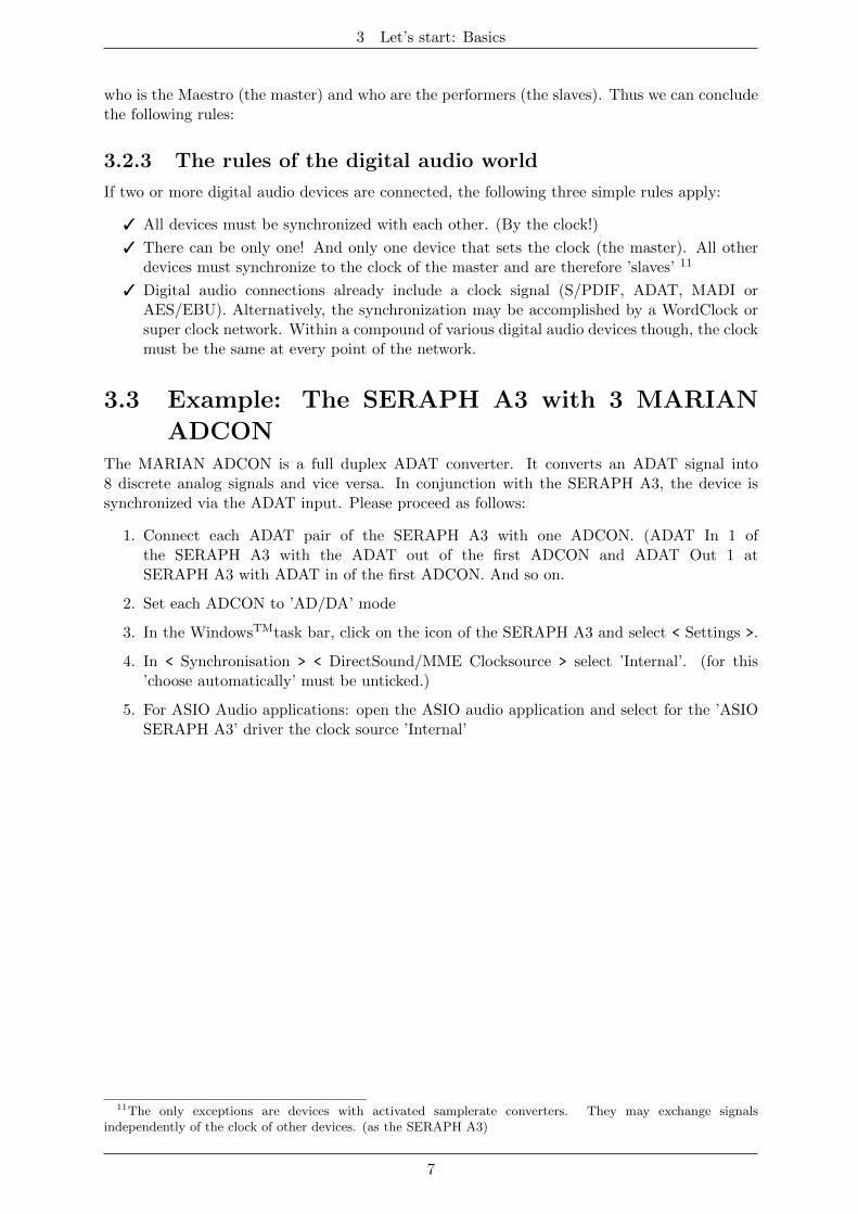
1. Click on the SERAPH A3 manager in the task bar andselect ’Mixer’.
2. For a stereo signal, connect two channels with the linkbutton at the bottom of the 1. channel strip.
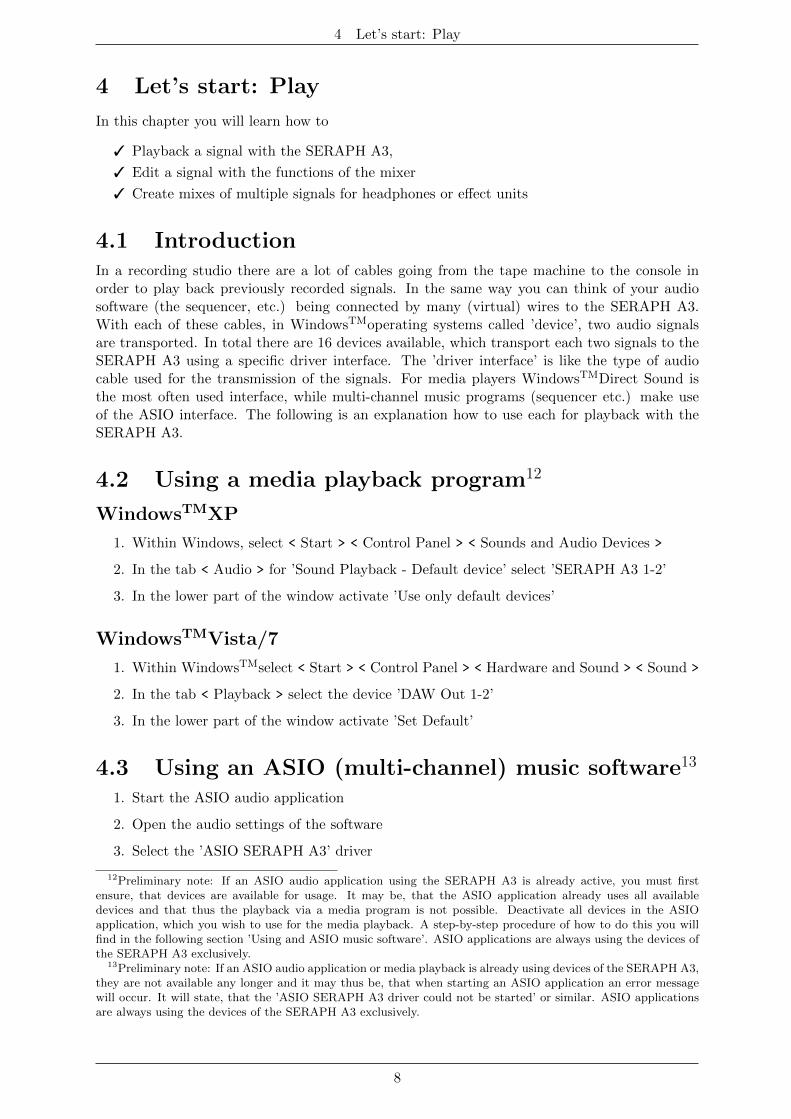
3. Choose ’DAW Out 1’ from the list at the top of thechannel strip for the left channel and ’DAW Out 2’ forthe right channel.
4. Navigate via the mixer or again through the manager iconin the taskbar to the ’routing’.
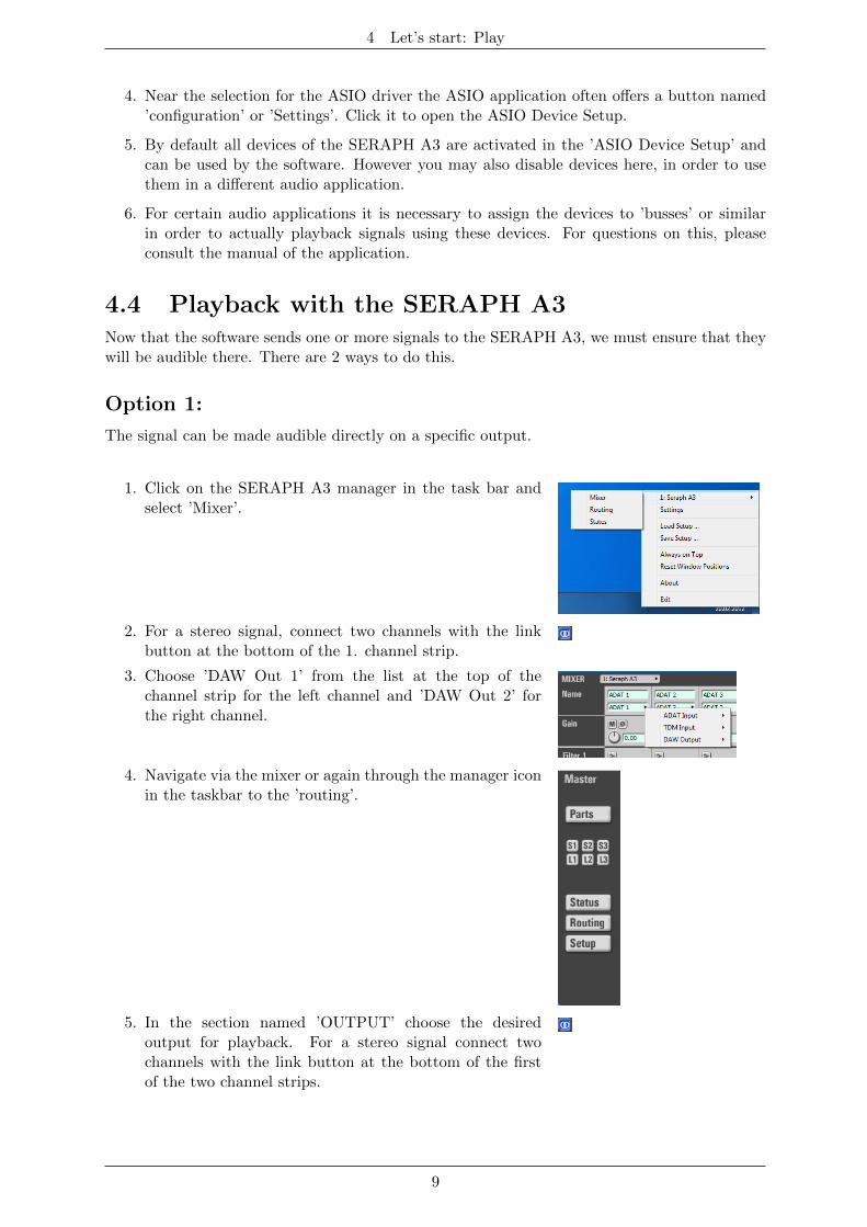
5. In the section named ’OUTPUT’ choose the desiredoutput for playback. For a stereo signal connect twochannels with the link button at the bottom of the firstof the two channel strips.
9
4 Let’s start: Play
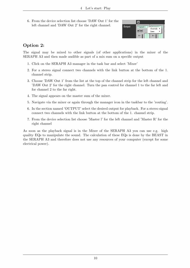
6. From the device selection list choose ’DAW Out 1’ for theleft channel and ’DAW Out 2’ for the right channel.
Option 2:
The signal may be mixed to other signals (of other applications) in the mixer of theSERAPH A3 and then made audible as part of a mix sum on a specific output
1. Click on the SERAPH A3 manager in the task bar and select ’Mixer’
2. For a stereo signal connect two channels with the link button at the bottom of the 1.channel strip.
3. Choose ’DAW Out 1’ from the list at the top of the channel strip for the left channel and’DAW Out 2’ for the right channel. Turn the pan control for channel 1 to the far left andfor channel 2 to the far right.
4. The signal appears on the master sum of the mixer.
5. Navigate via the mixer or again through the manager icon in the taskbar to the ’routing’.
6. In the section named ’OUTPUT’ select the desired output for playback. For a stereo signalconnect two channels with the link button at the bottom of the 1. channel strip.
7. From the device selection list choose ’Master l’ for the left channel and ’Master R’ for theright channel
As soon as the playback signal is in the Mixer of the SERAPH A3 you can use e.g. highquality EQs to manipulate the sound. The calculation of these EQs is done by the BEAST inthe SERAPH A3 and therefore does not use any resources of your computer (except for someelectrical power).
10
4 Let’s start: Play
4.5 Editing the Sound of SignalsThis is how you do it:
1. Choose the desired EQ, and activate it by clicking on one of the icons. Available are:
3 1x Low Shelf for processing the lower frequency band
3 2x peak for discreet interventions to specific frequencies/frequency ranges mostly inthe middle spectrum
3 1x High Shelf for processing the upper frequency band
2. With the control next to the display that shows an ’f’, set the desired frequency orbandwidth on which or from where on the equalizer should become active14.
3. With the control next to the display that shows a ’G’, set the desired boost or cut of thatfrequency or frequency band15.
4. With the control next to the display that shows a ’Q’, set the desired slope of the EQ.For a peak EQ, it determines how wide the modified frequency band will be (low valuesresult in a broad band). For a shelf EQ it determines on how many octaves a reduction orincrease is to become active (low values result in a large number of octaves - that means,a more gradual manipulation)
5. If the signal is to be made audibly directly on a specific output, you need to activate the’EQ’ button for this output. If the signal is part of a mix sum (e.g. the master output),the EQ button in the ’master’ section of this channel in the mixer must be activated.
4.6 Setting up a separate stereo headphone mix for
a musicianSuppose you are preparing a recording session and want the musicians to be able to listen tothemselves - but independent in all sound and volume aspects from the main mix that you hearin the studio. This is how you do it:
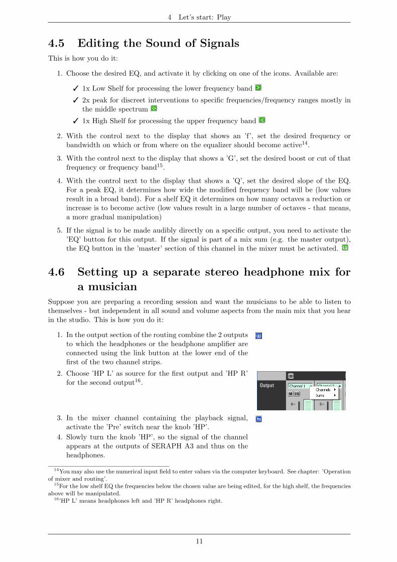
1. In the output section of the routing combine the 2 outputsto which the headphones or the headphone amplifier areconnected using the link button at the lower end of thefirst of the two channel strips.
2. Choose ’HP L’ as source for the first output and ’HP R’for the second output16.
3. In the mixer channel containing the playback signal,activate the ’Pre’ switch near the knob ’HP’.
4. Slowly turn the knob ’HP’, so the signal of the channelappears at the outputs of SERAPH A3 and thus on theheadphones.
14You may also use the numerical input field to enter values via the computer keyboard. See chapter: ’Operationof mixer and routing’.
15For the low shelf EQ the frequencies below the chosen value are being edited, for the high shelf, the frequenciesabove will be manipulated.
16’HP L’ means headphones left and ’HP R’ headphones right.
11
4 Let’s start: Play
5. Now you can change the monitor volume or put channelsin solo mode, without affecting the headphones. Ifdesired, you can make the EQs audible also on theheadphones. To do this simply activate the EQ switchfor ’HP L’17.
4.7 Feeding an external effects deviceSuppose you want to add an effect to a playback signal in the way as it is done with professionalmixing consoles - partially and depending on the current channel volume. This is how you doit:
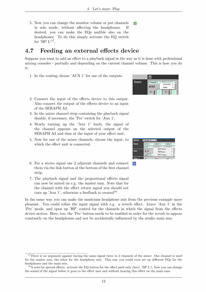
1. In the routing choose ’AUX 1’ for one of the outputs.
2. Connect the input of the effects device to this output.Also connect the output of the effects device to an inputof the SERAPH A3.
3. In the mixer channel strip containing the playback signaldisable, if necessary, the ’Pre’ switch for ’Aux 1’.
4. Slowly turning up the ’Aux 1’ knob, the signal ofthe channel appears on the selected output of theSERAPH A3 and thus at the input of your effect unit.
5. Now for one of the mixer channels, choose the input, towhich the effect unit is connected.
6. For a stereo signal use 2 adjacent channels and connectthem via the link button at the bottom of the first channelstrip.
7. The playback signal and the proportional effects signalcan now be mixed on e.g. the master sum. Note that forthe channel with the effect return signal you should notturn up ’Aux 1’, otherwise a feedback is created18.
In the same way you can make the musicians headphone mix from the previous example morepleasant. You could refine the input signal with e.g. a reverb effect. Leave ’Aux 1’ in the’Pre’ mode, and open up ’HP’ control for the channels in which the signal from the effectsdevice arrives. Here, too, the ’Pre’ button needs to be enabled in order for the reverb to appearconstantly on the headphones and not be accidentally influenced by the studio main mix.
17There is no argument against having the same signal twice in 2 channels of the mixer. One channel is usedfor the master mix, the other for the headphone mix. This way you could even set up different EQs for theheadphones and the main mix.
18A note for special effects: activate the EQ button for the effect path only (here: ’HP L’). Now you can changethe sound of the signal before it goes to the effect unit and without hearing this effect on the main sum.
12
5 Let’s start: Recording
5 Let’s start: Recording
In this chapter you will learn how to
3 Record a signal with the SERAPH A3
3 Record mixes of signals or individual signals from other software applications
5.1 IntroductionIn a recording studio there are a lot of cables going from the console to the tape machine in orderto play back previously recorded signals. In the same way you can think of the SERAPH A3 beingconnected by many (virtual) wires to the audio software (the sequencer, etc.). With each of thesecables, in WindowsTMoperating systems called ’device’, two audio signals are transported. Intotal there are 16 devices available, which transport each two signals to the application usinga specific driver interface. The ’driver interface’ is like the type of audio cable used for thetransmission of the signals. For media players WindowsTMDirectSound is the most often usedinterface, while multi-channel music programs (sequencer etc.) make use of the ASIO interface.The following is an explanation how to use each, for recording with the SERAPH A3.
5.2 Using a media playback program19
WindowsTMXP
1. Within Windows, select < Start > < Control Panel > < Sounds and Audio Devices >
2. In the tab < Audio > for ’Sound Recording - Default device’ select ’SERAPH A3 1-2’
3. In the lower part of the window activate ’Use only default devices’
WindowsTMVista/7
1. Within WindowsTMselect < Start > < Control Panel > < Hardware and Sound > < Sound >
2. In the tab < Recording > select the device ’DAW In 1-2’
3. In the lower part of the window activate ’Set Default’
5.3 Using an ASIO (multi-channel) music software20
1. Start the ASIO audio application
2. Open the audio settings of the software
3. Select the ’ASIO SERAPH A3’ driver
4. Near the selection for the ASIO driver the ASIO application often offers a button named’configuration’ or ’Settings’. Click it to open the ASIO Device Setup.
19Preliminary note: If an ASIO audio application using the SERAPH A3 is already active, you must firstensure, that devices are available for usage. It may be, that the ASIO application already uses all availabledevices and that thus the playback via a media program is not possible. Deactivate all devices in the ASIOapplication, which you wish to use for the media playback. A step-by-step procedure of how to do this you willfind in the following section ’Using and ASIO music software’. ASIO applications are always using the devices ofthe SERAPH A3 exclusively.
20Preliminary note: If an ASIO audio application or media playback is already using devices of the SERAPH A3,they are not available any longer and it may thus be that when starting an ASIO application an error messagewill occur. It will state, that the ’ASIO SERAPH A3 driver could not be started’ or similar. ASIO applicationsare always using the devices of the SERAPH A3 exclusively.
13
5 Let’s start: Recording
5. By default all devices of the SERAPH A3 are activated in the ’ASIO Device Setup’ andcan be used by the software. However you may also disable devices here, in order to usethem in a different audio application.
6. For certain audio applications it is necessary to assign the devices to ’busses’ or similarin order to actually playback signals using these devices. For questions on this, pleaseconsult the manual of the application.
5.4 Assignment in the SERAPH A3 routingIn order for a specific signal to appear in the audio application with the device ’SERAPH A3 1-2’the proper setting has to be done in the routing of the SERAPH A3.
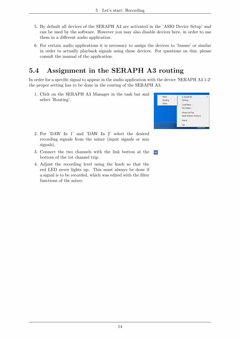
1. Click on the SERAPH A3 Manager in the task bar andselect ’Routing’.
2. For ’DAW In 1’ and ’DAW In 2’ select the desiredrecording signals from the mixer (input signals or mixsignals).
3. Connect the two channels with the link button at thebottom of the 1st channel trip.
4. Adjust the recording level using the knob so that thered LED never lights up. This must always be done ifa signal is to be recorded, which was edited with the filterfunctions of the mixer.
14
6 The SERAPH A3 in Detail: Mixing and Routing
6 The SERAPH A3 in Detail: Mixing and Routing
In this chapter you will learn
3 To understand in detail the signal flow of the BEAST
3 Operating the Mixer and the Routing via mouse/keyboard and MIDI
3 all function of all controls of Mixer and Routing
3 Saving setups and snapshots for Total Recall
6.1 IntroductionThe SERAPH A3 is more than ’just’ a sound card. It features a full-scale mixing console (mixer)and a multi-functional Patchbay (Routing) - called BEAST. The BEAST is integrated21 in thehardware of the SERAPH A3 thus avoiding any additional processing load for the host computerand guaranteeing a nearly latency-free signal processing. It is controlled by a software that wasinstalled on your computer along with the driver. In the WindowsTMtaskbar you can find thesymbol for the SERAPH A3. With a simple mouse click on it, a context menu is opened. Select’Mixer’ and ’Routing’. If several SERAPH A3 are installed, all entries are displayed accordingto their number with ’nr. 1’, ’nr. 2’, etc.
All signals fed to the SERAPH A3 either through connected external cables or signals from asoftware of the computer, and any signals that are to be played back with the SERAPH A3 passat some point the mixer and thus the routing. You can imagine this as follows:
1. A big multi-core with 32 cables passes from the operating system (one or more audioapplications on the computer) to the mixer of the SERAPH A3. These 32 playbacksignals of the multi core are called ’DAW Out 1’ to ’DAW Out 32’.
2. From the routing of the SERAPH A3 to the operating system of the computer there isanother multi-core with 32 cables. These 32 recording signals, we call ’DAW In 1’ to ’DAWIn 32’.
3. Furthermore, in the mixer all signals of all physical inputs are available. These signals ofthe 24 ADAT inputs we therefore call ’INPUT 1’ to ’INPUT 24 ’. The signals of the TDMSyncBus are available as ’TDM 1’ to ’TDM 8’ 22
4. Signals leaving the SERAPH A3 by a routing to a specific physical output we call’OUTPUT’. The SERAPH A3 has 32 outputs: 24 signals via ADAT outputs and 8 signalsvia the TDM bus 23.
In the chapters ’The Mixer in Detail’ and ’The Routing in detail’ you can find out how all thesignals can be processed and managed.
6.2 Operation of Mixer and Routing
Operation with keyboard and mouse
All elements of the mixer and the routing may be operated or moved by the computer mouse.Knobs are opened/closed by circular movement of the mouse. The further the mouse is fromthe center of the knob the finer the adjustment of the values will be. Alternatively the mousewheel can be used. While holding the <Ctrl>-key simultaneously, a fine adjustment can beachieved. Holding the <shift>-key will coarse through the parameter. After double-clicking anumeric field, the value of a knob may also be entered in dB via the computer keyboard. Theentry is confirmed with the Enter key.
21Proper security measures were undertaken to keep it this way.22Every ADAT stream features 8 signals. In S/MUX mode the amount of signals is cut in half per ADAT
stream. In this case only ’INPUT 1’ to ’INPUT 12’ are available. Changing between ADAT mode and S/MUXmode is done in the settings of the SERAPH A3.
23In S/MUX mode 12 signals.
15
6 The SERAPH A3 in Detail: Mixing and Routing
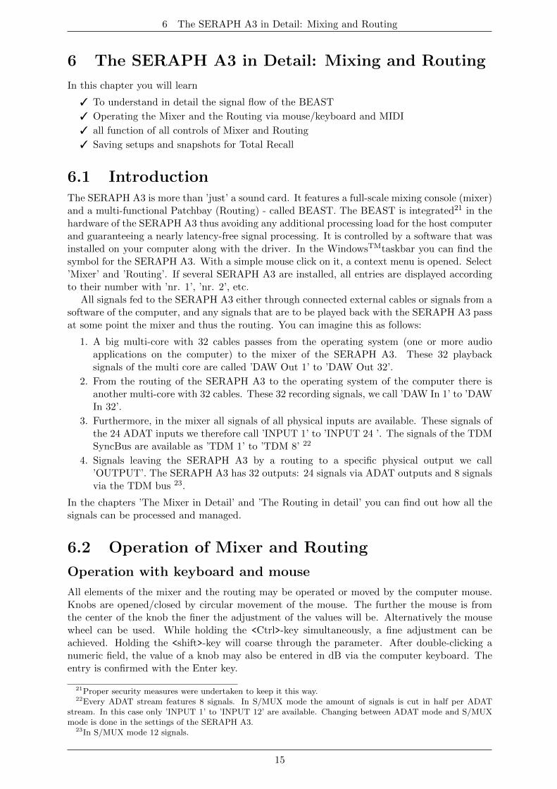
6.3 View optionsIn order to change the look of the mixer, single rows of controlelements may be shown or hidden in the ’Parts’ section. Thisapplies for rows 1-4 of the filter as well as all Aux-knobs.
Additionally for mixer and routing the window may be changed inhorizontal size. This happens in segments. Via the direction arrowsin the right lower corner of the mixer or the routing the displayedsection may be switched.
All these functions are very useful for e.g. saving preciousspace on the computer screen, but also if you set up specialconfigurations with the knobs and wish to inhibit accidental changesby intentionally hiding them. If several SERAPH A3 are installed,the selection menu in the upper frame of the window allows callingup the corresponding instance.
The lock symbol in the upper right of the window inhibits coverageby other windows. Thereby mixer or routing will always be in theforeground and visable.
In the lower left area there are three more function switches.’Setup’ opens up a context menu that is equivalent to the menuopened from SERAPH A3 symbol in the task bar. This againallows for fast access to important functions and windows of theSERAPH A3 sound system.
’Routing’ calls up the routing window. From there again you canswitch quickly to the mixer window via the ’mixer’ button. ’Status’opens the clock status panel.
16
6 The SERAPH A3 in Detail: Mixing and Routing
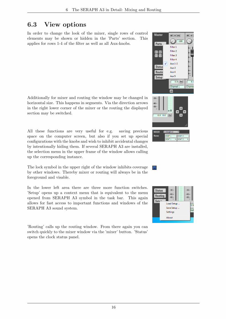
6.4 SnapshotsOnce a visual configuration was made, it may be saved along with the current mixersettings in one of up to 3 ’snapshots’. To achieve this, click ’S1’ to ’S3’. If a snapshotis to be recalled, click on the corresponding ’L1’ to ’L3’ button. All snapshots aresaved along with a setup.
6.5 SetupsAs opposed to snapshots, setups can save and recall all current settings of the SERAPH A3 mixerand routing as well as possible MIDI assignments in one single file.
A click on ’save setup...’ opens the WindowsTMfile selection dialog in order to select the pathand the name of a setup24. Of course, several setups may be saved. By clicking ’load setup...’the WindowsTMfile selection dialog is opened to navigate to the location of a previously savedsetup. If you choose a file, click ’open’ and all settings of mixer and routing will be deleted andreplaced by the settings of this setup/file.
24Use comprehensive names for the files of a setup. This will make it easier later on!
17
6 The SERAPH A3 in Detail: Mixing and Routing
6.6 The mixer in detail
General
The Mixer of the SERAPH A3 offers an abundance of functions for mixing and soundmanipulation of signals of a software (’DAW Out x’) or a physical input (’INPUT x’) Thusall signals of the 64 channels may be mixed upon 8 sums25 and changed in sound by up to 4filters. The handling and signal flow of this is designed similarly to those of hardware mixingdesks. This concerns the possibility to
1. create different mixes for the sound engineer and the musicians (using pre aux mixes)
2. send signals of single channels to external effect devices (using post aux mixes) as well as
3. to solo or to mute signals, as well as changing their phase and to define their position inthe stereo mix
Differences of the SERAPH A3 mixers in comparison to hardware mixing desks are the possibilityto
1. assign signals in any order and also multiply to the channels of the mixer26
2. to save all settings of all knobs in different setups27
3. to activate the filters of a channel selectively only on specific mix sums or to have eachsignal available with or without filter
For samplerates up to 96kHz, the Seraph mixer allows for setting up 8 mix sums. 2 Mix sumsare the master sum. It serves well as the mains for the sound engineer in the studio. Further 2mix sum assemble the stereo headphone mix (’HP’). The other 4 sums named ’Aux 1’ to ’Aux4’ have been designed for applications like headphone mixes or effect feeds.
For samplerates above 96kHz, there are the stereo master sum and 2 more aux28.
Channel strip
Each channelstrip of the mixer is built up and organized identically. The following explanationof the elements of it is thereby an example for all. Two adjacent channel strips may be connectedinto a stereo pair using the ’link’-button at the lower end of the mixer. This will link all controlelements excluding the channel input selection, the phase switch as well as gain-, aux- andbalance knobs.
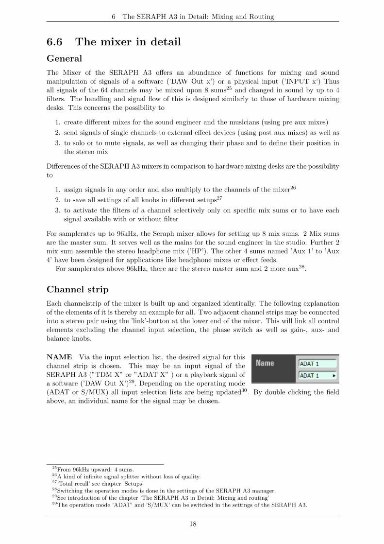
NAME Via the input selection list, the desired signal for thischannel strip is chosen. This may be an input signal of theSERAPH A3 (”TDM X” or ”ADAT X” ) or a playback signal ofa software (’DAW Out X’)29. Depending on the operating mode(ADAT or S/MUX) all input selection lists are being updated30. By double clicking the fieldabove, an individual name for the signal may be chosen.
25From 96kHz upward: 4 sums.26A kind of infinite signal splitter without loss of quality.27’Total recall’ see chapter ’Setups’28Switching the operation modes is done in the settings of the SERAPH A3 manager.29See introduction of the chapter ’The SERAPH A3 in Detail: Mixing and routing’30The operation mode ’ADAT’ and ’S/MUX’ can be switched in the settings of the SERAPH A3.
18
6 The SERAPH A3 in Detail: Mixing and Routing
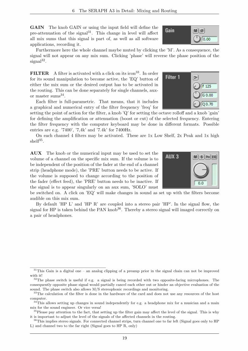
GAIN The knob GAIN or using the input field will define thepre-attenuation of the signal31. This change in level will affectall mix sums that this signal is part of, as well as all softwareapplications, recording it.
Furthermore here the whole channel maybe muted by clicking the ’M’. As a consequence, thesignal will not appear on any mix sum. Clicking ’phase’ will reverse the phase position of thesignal32.
FILTER A filter is activated with a click on its icon33. In orderfor its sound manipulation to become active, the ’EQ’ button ofeither the mix sum or the desired output has to be activated inthe routing. This can be done separately for single channels, aux-or master sums34.
Each filter is full-parametric. That means, that it includesa graphical and numerical entry of the filter frequency ’freq’ forsetting the point of action for the filter, a knob ’Q’ for setting the octave rolloff and a knob ’gain’for defining the amplification or attenuation (boost or cut) of the selected frequency. Enteringthe filter frequency with the computer keyboard may be done in different formats. Possibleentries are e.g. ’7400’, ’7,4k’ and ’7.4k’ for 7400Hz.
On each channel 4 filters may be activated. These are 1x Low Shelf, 2x Peak and 1x highshelf35.
AUX The knob or the numerical input may be used to set thevolume of a channel on the specific mix sum. If the volume is tobe independent of the position of the fader at the end of a channelstrip (headphone mode), the ’PRE’ button needs to be active. Ifthe volume is supposed to change according to the position ofthe fader (effect feed), the ’PRE’ button needs to be inactive. Ifthe signal is to appear singularly on an aux sum, ’SOLO’ mustbe switched on. A click on ’EQ’ will make changes in sound as set up with the filters becomeaudible on this mix sum.
By default ’HP L’ and ’HP R’ are coupled into a stereo pair ’HP’. In the signal flow, thesignal for HP is taken behind the PAN knob36. Thereby a stereo signal will imaged correctly ona pair of headphones.
31This Gain is a digital one – an analog clipping of a preamp prior in the signal chain can not be improvedwith it!
32The phase switch is useful if e.g. a signal is being recorded with two opposite-facing microphones. Theconsequently opposite phase signal would partially cancel each other out or hinder an objective evaluation of thesound. The phase switch also allows M/S stereophonic recordings and monitoring.
33The calculation of the filter is done in the hardware of the card and does not use any resources of the hostcomputer.
34This allows setting up changes in sound independently for e.g. a headphone mix for a musician and a mainmix for the sound engineer. Or vice versa!
35Please pay attention to the fact, that setting up the filter gain may affect the level of the signal. This is whyit is important to adjust the level of the signals of the affected channels in the routing.
36This implies stereo signals. For connected channel strips, turn channel one to far left (Signal goes only to HPL) and channel two to the far right (Signal goes to HP R, only)
19
6 The SERAPH A3 in Detail: Mixing and Routing
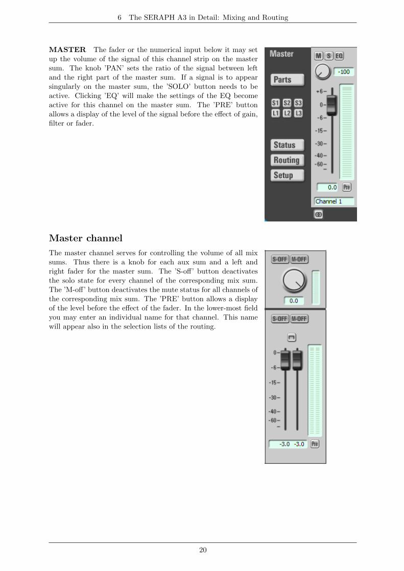
MASTER The fader or the numerical input below it may setup the volume of the signal of this channel strip on the mastersum. The knob ’PAN’ sets the ratio of the signal between leftand the right part of the master sum. If a signal is to appearsingularly on the master sum, the ’SOLO’ button needs to beactive. Clicking ’EQ’ will make the settings of the EQ becomeactive for this channel on the master sum. The ’PRE’ buttonallows a display of the level of the signal before the effect of gain,filter or fader.
Master channel
The master channel serves for controlling the volume of all mixsums. Thus there is a knob for each aux sum and a left andright fader for the master sum. The ’S-off’ button deactivatesthe solo state for every channel of the corresponding mix sum.The ’M-off’ button deactivates the mute status for all channels ofthe corresponding mix sum. The ’PRE’ button allows a displayof the level before the effect of the fader. In the lower-most fieldyou may enter an individual name for that channel. This namewill appear also in the selection lists of the routing.
20
6 The SERAPH A3 in Detail: Mixing and Routing
6.7 The routing in detail
General
The routing of the SERAPH A3 is a complex digital patchbay. All signals of the channels of themixer as well as the mix sums (’master’, ’HP’ and ’Aux x’) may be played back on any physicaloutput (via the ’output’ section) or may be recorded within the same computer system (via the’DAW Input’ section). Additionally for every single channel you may define, if the changes insound by the filter may become active or not on the routed output37.
DAW In section
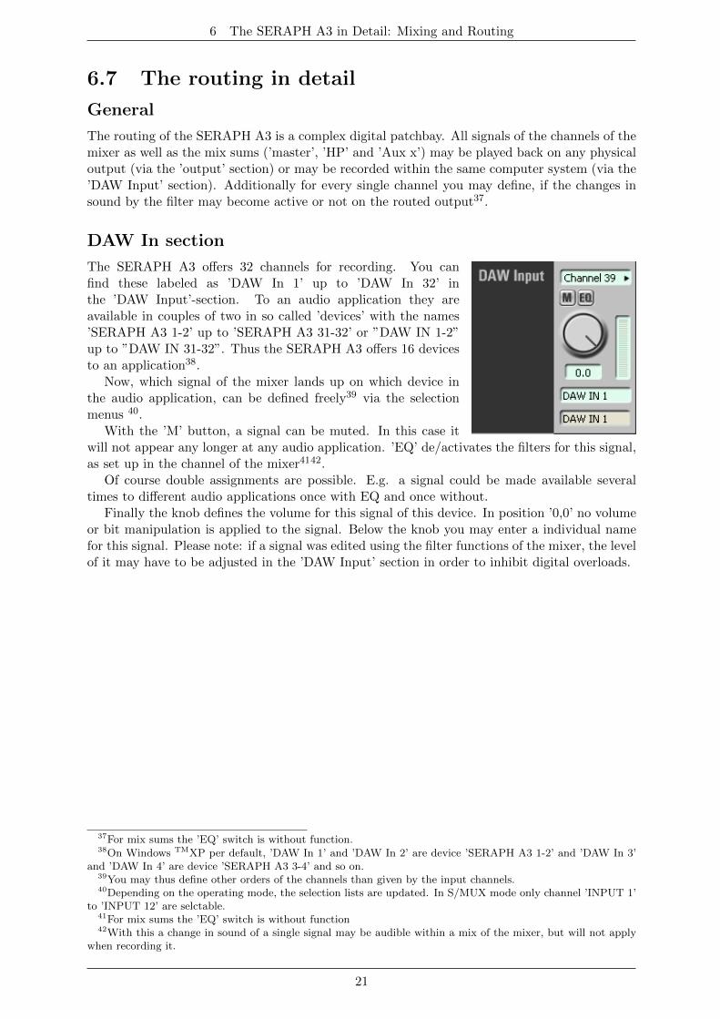
The SERAPH A3 offers 32 channels for recording. You canfind these labeled as ’DAW In 1’ up to ’DAW In 32’ inthe ’DAW Input’-section. To an audio application they areavailable in couples of two in so called ’devices’ with the names’SERAPH A3 1-2’ up to ’SERAPH A3 31-32’ or ”DAW IN 1-2”up to ”DAW IN 31-32”. Thus the SERAPH A3 offers 16 devicesto an application38.
Now, which signal of the mixer lands up on which device inthe audio application, can be defined freely39 via the selectionmenus 40.
With the ’M’ button, a signal can be muted. In this case itwill not appear any longer at any audio application. ’EQ’ de/activates the filters for this signal,as set up in the channel of the mixer4142.
Of course double assignments are possible. E.g. a signal could be made available severaltimes to different audio applications once with EQ and once without.
Finally the knob defines the volume for this signal of this device. In position ’0,0’ no volumeor bit manipulation is applied to the signal. Below the knob you may enter a individual namefor this signal. Please note: if a signal was edited using the filter functions of the mixer, the levelof it may have to be adjusted in the ’DAW Input’ section in order to inhibit digital overloads.
37For mix sums the ’EQ’ switch is without function.38On Windows TMXP per default, ’DAW In 1’ and ’DAW In 2’ are device ’SERAPH A3 1-2’ and ’DAW In 3’
and ’DAW In 4’ are device ’SERAPH A3 3-4’ and so on.39You may thus define other orders of the channels than given by the input channels.40Depending on the operating mode, the selection lists are updated. In S/MUX mode only channel ’INPUT 1’
to ’INPUT 12’ are selctable.41For mix sums the ’EQ’ switch is without function42With this a change in sound of a single signal may be audible within a mix of the mixer, but will not apply
when recording it.
21
7 The SERAPH A3 in Detail: System settings
Output section
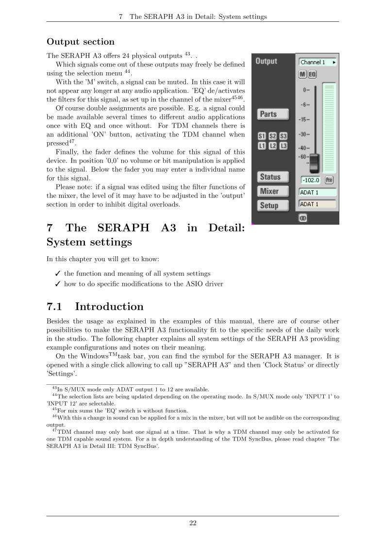
The SERAPH A3 offers 24 physical outputs 43. .Which signals come out of these outputs may freely be defined
using the selection menu 44.With the ’M’ switch, a signal can be muted. In this case it will
not appear any longer at any audio application. ’EQ’ de/activatesthe filters for this signal, as set up in the channel of the mixer4546.
Of course double assignments are possible. E.g. a signal couldbe made available several times to different audio applicationsonce with EQ and once without. For TDM channels there isan additional ’ON’ button, activating the TDM channel whenpressed47.
Finally, the fader defines the volume for this signal of thisdevice. In position ’0,0’ no volume or bit manipulation is appliedto the signal. Below the fader you may enter a individual namefor this signal.
Please note: if a signal was edited using the filter functions ofthe mixer, the level of it may have to be adjusted in the ’output’section in order to inhibit digital overloads.
7 The SERAPH A3 in Detail:
System settings
In this chapter you will get to know:
3 the function and meaning of all system settings
3 how to do specific modifications to the ASIO driver
7.1 IntroductionBesides the usage as explained in the examples of this manual, there are of course otherpossibilities to make the SERAPH A3 functionality fit to the specific needs of the daily workin the studio. The following chapter explains all system settings of the SERAPH A3 providingexample configurations and notes on their meaning.
On the WindowsTMtask bar, you can find the symbol for the SERAPH A3 manager. It isopened with a single click allowing to call up ”SERAPH A3” and then ’Clock Status’ or directly’Settings’.
43In S/MUX mode only ADAT output 1 to 12 are available.44The selection lists are being updated depending on the operating mode. In S/MUX mode only ’INPUT 1’ to
’INPUT 12’ are selectable.45For mix sums the ’EQ’ switch is without function.46With this a change in sound can be applied for a mix in the mixer, but will not be audible on the corresponding
output.47TDM channel may only host one signal at a time. That is why a TDM channel may only be activated for
one TDM capable sound system. For a in depth understanding of the TDM SyncBus, please read chapter ’TheSERAPH A3 in Detail III: TDM SyncBus’.
22
7 The SERAPH A3 in Detail: System settings
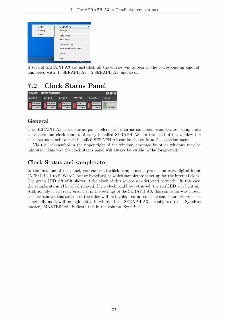
If several SERAPH A3 are installed, all the entries will appear in the corresponding amount,numbered with ’1: SERAPH A3’, ’2:SERAPH A3’ and so on.
7.2 Clock Status Panel
General
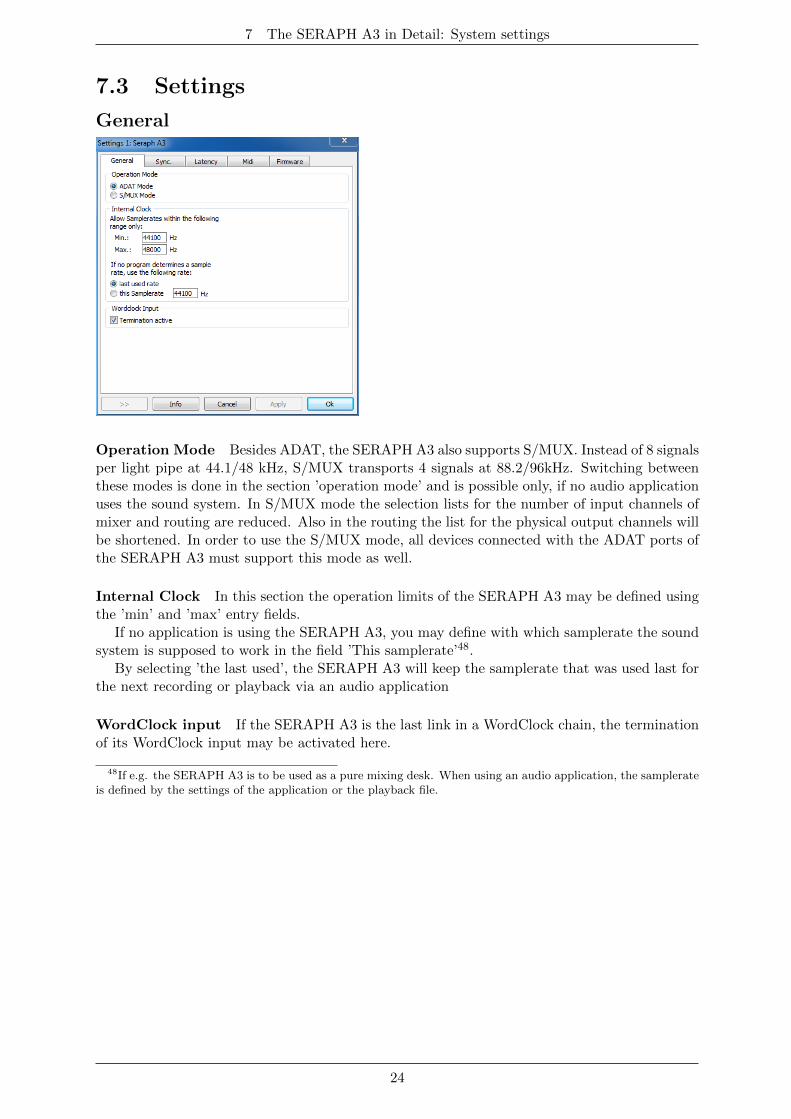
The SERAPH A3 clock status panel offers fast information about samplerates, samplerateconverters and clock sources of every installed SERAPH A3. In the head of the window theclock status panel for each installed SERAPH A3 can be chosen from the selection menu.
Via the lock-symbol in the upper right of the window, coverage by other windows may beinhibited. This way the clock status panel will always be visible in the foreground.
Clock Status and samplerate
In the first line of the panel, you can read which samplerate is present on each digital input(AES/EBU 1 to 8, WordClock or SyncBus) or which samplerate is set up for the internal clock.The green LED left of it shows, if the clock of this source was detected correctly. In this casethe samplerate in kHz will displayed. If no clock could be retrieved, the red LED will light up.Additionally it will read ’error’. If in the settings of the SERAPH A3, this connector was chosenas clock source, this section of the table will be highlighted in red. The connector, whose clockis actually used, will be highlighted in white. If the SERAPH A3 is configured to be SyncBusmaster, ’MASTER’ will indicate this in the column ’SyncBus’.
23
7 The SERAPH A3 in Detail: System settings
7.3 Settings
General
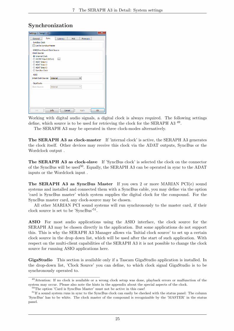
Operation Mode Besides ADAT, the SERAPH A3 also supports S/MUX. Instead of 8 signalsper light pipe at 44.1/48 kHz, S/MUX transports 4 signals at 88.2/96kHz. Switching betweenthese modes is done in the section ’operation mode’ and is possible only, if no audio applicationuses the sound system. In S/MUX mode the selection lists for the number of input channels ofmixer and routing are reduced. Also in the routing the list for the physical output channels willbe shortened. In order to use the S/MUX mode, all devices connected with the ADAT ports ofthe SERAPH A3 must support this mode as well.
Internal Clock In this section the operation limits of the SERAPH A3 may be defined usingthe ’min’ and ’max’ entry fields.
If no application is using the SERAPH A3, you may define with which samplerate the soundsystem is supposed to work in the field ’This samplerate’48.
By selecting ’the last used’, the SERAPH A3 will keep the samplerate that was used last forthe next recording or playback via an audio application
WordClock input If the SERAPH A3 is the last link in a WordClock chain, the terminationof its WordClock input may be activated here.
48If e.g. the SERAPH A3 is to be used as a pure mixing desk. When using an audio application, the samplerateis defined by the settings of the application or the playback file.
24
7 The SERAPH A3 in Detail: System settings
Synchronization
Working with digital audio signals, a digital clock is always required. The following settingsdefine, which source is to be used for retrieving the clock for the SERAPH A3 49.
The SERAPH A3 may be operated in three clock-modes alternatively.
The SERAPH A3 as clock-master If ’internal clock’ is active, the SERAPH A3 generatesthe clock itself. Other devices may receive this clock via the ADAT outputs, SyncBus or theWordclock output .
The SERAPH A3 as clock-slave If ’SyncBus clock’ is selected the clock on the connectorof the SyncBus will be used50. Equally, the SERAPH A3 can be operated in sync to the ADATinputs or the Wordclock input .
The SERAPH A3 as SyncBus Master If you own 2 or more MARIAN PCI(e) soundsystems and installed and connected them with a SyncBus cable, you may define via the option’card is SyncBus master’ which system supplies the digital clock for the compound. For theSyncBus master card, any clock-source may be chosen.
All other MARIAN PCI sound systems will run synchronously to the master card, if theirclock source is set to be ’SyncBus’51.
ASIO For most audio applications using the ASIO interface, the clock source for theSERAPH A3 may be chosen directly in the application. But some applications do not supportthis. This is why the SERAPH A3 Manager allows via ’Initial clock source’ to set up a certainclock source in the drop down list, which will be used after the start of such application. Withrespect on the multi-client capabilities of the SERAPH A3 it is not possible to change the clocksource for running ASIO applications here.
GigaStudio This section is available only if a Tascam GigaStudio application is installed. Inthe drop-down list, ’Clock Source’ you can define, to which clock signal GigaStudio is to besynchronously operated to.
49Attention: If no clock is available or a wrong clock setup was done, playback errors or malfunction of thesystem may occur. Please also note the hints in the appendix about the special aspects of the clock.
50The option ’Card is SyncBus Master’ must not be active in this case!51If a sound system runs in sync to the SyncBus clock can easily be checked with the status panel: The column
’SyncBus’ has to be white. The clock master of the compound is recognizable by the ’MASTER’ in the statuspanel.
25
7 The SERAPH A3 in Detail: System settings
Latency
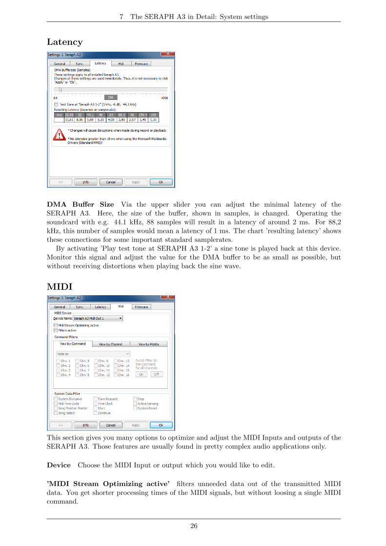
DMA Buffer Size Via the upper slider you can adjust the minimal latency of theSERAPH A3. Here, the size of the buffer, shown in samples, is changed. Operating thesoundcard with e.g. 44.1 kHz, 88 samples will result in a latency of around 2 ms. For 88,2kHz, this number of samples would mean a latency of 1 ms. The chart ’resulting latency’ showsthese connections for some important standard samplerates.
By activating ’Play test tone at SERAPH A3 1-2’ a sine tone is played back at this device.Monitor this signal and adjust the value for the DMA buffer to be as small as possible, butwithout receiving distortions when playing back the sine wave.
MIDI
This section gives you many options to optimize and adjust the MIDI Inputs and outputs of theSERAPH A3. Those features are usually found in pretty complex audio applications only.
Device Choose the MIDI Input or output which you would like to edit.
’MIDI Stream Optimizing active’ filters unneeded data out of the transmitted MIDIdata. You get shorter processing times of the MIDI signals, but without loosing a single MIDIcommand.
26
7 The SERAPH A3 in Detail: System settings
’Filters active’ enables all configured MIDI filter options. For most comfortable editing, youcan change the look of the section ’command filters’. There are 3 viewing modes available:
1. ’View by Command’, ’Command Filters’ shows the MIDI commands, which can now befiltered for each single channel. By clicking ’On’ or ’Off’, the chosen MIDI command isfiltered or passed through on all channels.
2. ’View by Channel’, ’Command Filters’ shows all MIDI channels, on which the MIDIcommands can now be filtered.
3. ’View by Matrix’ all MIDI channels and the MIDI command filters are shown in form ofa matrix.
System Data Filter The command filters offered here are MIDI channel independent, butconcern the chosen MIDI port.
Firmware
This section you may ignore. Also it is not necessary to manually perform firmware updates,since this is done automatically along with a driver update.
Note: This section may become relevant, if, after contacting the MARIAN Support Service,it is advised to perform a manual firmware update – e.g. for diagnostic purposes.
7.4 ASIO Device Setup
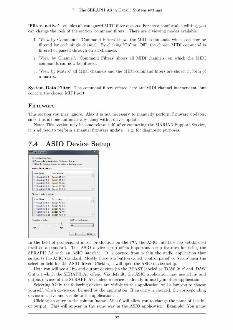
In the field of professional music production on the PC, the ASIO interface has establisheditself as a standard. The ASIO device setup offers important setup features for using theSERAPH A3 with an ASIO interface. It is opened from within the audio application thatsupports the ASIO standard. Mostly there is a button called ’control panel’ or ’setup’ near theselection field for the ASIO driver. Clicking it will open the ASIO device setup.
Here you will see all in- and output devices (in the BEAST labeled as ’DAW In x’ and ’DAWOut x’) which the SERAPH A3 offers. Via default, the ASIO application may use all in- andoutput devices of the SERAPH A3, unless a device is already in use by another application.
Selecting ’Only the following devices are visible to this application’ will allow you to chooseyourself, which device can be used by the application. If an entry is checked, the correspondingdevice is active and visible to the application.
Clicking an entry in the column ’name (Alias)’ will allow you to change the name of this in-or output. This will appear in the same way in the ASIO application. Example: You name
27
7 The SERAPH A3 in Detail: System settings
’SERAPH A3 1-2’ to ’guitar’ or ’room mic’. Now in the audio application you will always seeat first glance which signal comes from where.
On the left lower side of the window you can find the ’execution priority’ slider. It can befreely positioned between ’low’ and ’high’. In position ’high’ the transfer of the audio databetween ASIO application and SERAPH A3 will receive the highest priority. This means, thatthe processor will handle this data preferably.
In position ’low’ the calculation of plug in effects will receive the highest priority and theaudio data transfer will be dealt with secondarily. On the lower right side of the window youcan find a selection menu for ’Buffersize in Samples’. This value defines the latency of the audiodata transfer. An example: working with 44.1kHz and setting up 176 samples as buffersize willresult in a latency of 4ms. When working with 88.2kHz, the same buffersize will result in alatency of 2ms.
28
8 The SERAPH A3 in Detail: TDM SyncBus
8 The SERAPH A3 in Detail: TDM SyncBus
In this chapter you will learn
3 to understand the TDM SyncBus via metaphors
3 to use the TDM SyncBus via examples
8.1 Principles of the TDM SyncBusThe TDM SyncBus is a collective transport bus for digital audio- and synchronization signals.With the help of the TDM SyncBus any signal of an audio system featuring the TDM SyncBusmay be send out to other MARIAN sound cards with TDM SyncBus.
The principle of operation of the TDM SyncBus may be compared quite well with thepneumatic dispatch or tube system between several office buildings.
Imagine this: Ms. Smith in building 1 sends out a press report on channel 1 of the tubesystem. It arrives at the distribution central. If Mr. Mayer in the 2. building wishes to readthe report, he needs to call for it at the central. He will then receive a copy of it in the inbox ofchannel 1.
The same way as Ms. Smith uses a tube channel to send out a document between buildings,you can use a TDM channel to send out a signal of the SERAPH A3to the TDM SyncBus viathe routing. The same way as Mr. Mayer receives a copy of the document in the inbox, theaudio signal of the TDM SyncBus lands up in the input of the mixer of the connected MARIANTDM system.
This is also possible: Mr. Miller from building 3 may also request the message of Ms. Smith.For this, the distribution central simply copies the document another time and sends it to Mr.Miller.
That means: If more than 2 MARIAN sound cards with TDM SyncBus are installed in acomputer, the signals of the TDM channel are available to all the systems as well.
BUT: The capacities of the pneumatic dispatch are limited. E.g. if Mr. Miller building 3also wishes to send a document, he must not use channel 1, since Ms. Smith is already sendingout her documents here. All in all there are 8 channels, that’s why Mr. Miller must decide forchannel 2 to 8.
For the TDM SyncBus this means: only one signal52 in one channel but eight signals in totalcan be distributed simultaneously. That’s another way to say that a specific TDM channel mayonly be active in one routing at a time.
8.2 Examples the functionality of the TDM SyncBus
Synchronizing other MARIAN sound systems
As explained in ’Let’s start I: Basics’, all digital systems working together have to besynchronized by one clock. This is what you need to do to synchronize MARIAN sound systemsusing the TDM SyncBus
1. For the system that is supposed to provide the clock, choose ’Card is SyncBus master’ inthe settings of that system.
2. For all other systems deactivate the aforementioned option. Choose ’SyncBus’ or ’TDMSyncBus’ as clock source in
(a) The ASIO application when using the ASIO interface
(b) In the settings of the sound system when using any other than the ASIO interface
52’One’ signal means ’one source’ – of course aux- and other mix signals can be sent.
29
8 The SERAPH A3 in Detail: TDM SyncBus
3. For the SyncBus or TDM SyncBus master system any valid clock source may be chosen.This may be the internal or any external clock53.
4. Open the status panel for every system involved and check the settings54.
5. If 2 or more TDM SyncBus systems are synchronized, they may also exchange Audiosignals via the TDM SyncBus
Including signals from other MARIAN sound systems in theBEAST
With the help of the TDM SyncBus up to 8 signals of an additional sound system may beintegrated in the mixer of the SERAPH A3. This is how you do it:
1. Synchronize all participating MARIAN TDM SyncBus systems as described in the previouschapter.
2. Open the routing of the system from which a signal is to be sent.
3. For any TDM channel in the output section, choose the desired signal from the selectionmenu.
4. Activate the ”ON” button of that TDM channel
5. The signal is now available in all connected MARIAN Soundsystems via the TDM SyncBus
53e.g. from ADAT, Wordclock or SyncBus54A description of the status panel you can find in the chapter ’The SERAPH A3 in Detail II: System Settings’
30
9 Appendix
9 Appendix
9.1 Service and Support
Warranty
Each SERAPH A3 leaving us is put under extensive functionality checks. We allow full 5 yearsof limited warranty. A copy of the receipt or bill serves as proof of purchase. If there is adeficiency occurring during the time of warranty, you can exchange the unit at your dealer.Damages originating in inappropriate handling or false operation are excluded from warranty.
You can still send the unit in to us for repair after the warranty has expired. You can decideto have it repaired, after receiving a calculation of the approximate repair costs. For this, pleaseget in contact with our support service.
ContactIf you have any questions or problems when installing or operating the SERAPH A3, pleaseproceed as follows:
1. Make sure, the newest driver is installed. The current driver files can be found on:www.MARIAN.de/en/downloads
2. If still any questions remain, you can contact us via the internet using our support format: www.MARIAN.de/en/support
3. Or talk to us personally. Dial: +49 341 589 32 22
Interesting news, information as well as information about our products and authorized dealerscan be found on www.MARIAN.de.
31
9 Appendix
9.2 GlossaryASIO ASIO stands for ’Audio Streaming Input Output’ and is a driver interface for soundcardsdeveloped by the company Steinberg. With ASIO very small latency times can be achieved. TheASIO driver is not multi-client capable. That means, different audio applications may not usethe same audio device simultaneously.
Audio Device In the field of digital audio processing, this mostly names an input or outputof an audio system, the way it appears in an audio application.
Aux In the audio world ’Aux’ or ’Auxiliary’ names an additional input or output. That meansa physical input or output or a mix signal besides the main mix signal.
Buffersize/Buffer When transporting audio data within a computer (e.g. recording orplaying back a signal), they are chopped in equal blocks called ’buffer’. That means, theyare a certain time frame out of a complete signal. The number and size of the buffer defines thedelay time (latency).
DAW DAW is the abbreviation for ’Digital Audio Workstation’ and names a softwareapplication installed on a computer, for numerous task of sound editing or a system consistingof one or several components for processing audio signals. E.g. a computer with software,appropriate interfaces and connections and additional control or input devices.
Direct Sound/Direct X DirectX is a WindowsTMsystem-software, which allows hardwaremanufacturers, to support different input-, graphic- or sound functions with their hardware andthereby accelerate it. DirectSound is a part of DirectX. A DirectSound driver creates less CPUload and enables faster latency times than a standard MME driver.
Driver A driver is a package of software, consisting of a couple of single programs or a partof a software, which ensures communication between a hardware device and other drivers orsoftware applications on standardized level. Certain interfaces are used doing this.
DSP DSP stands for ’Digital Signal Processing’. Most times this names an electricalcomponent, processing audio signals digitally. It calculates, for example, the sum of two signalsor an effect into an audio signal.
GSIF GSIF stands for ’GigaStudio InterFace’ and is a driver interface for soundcardsdeveloped by the company TASCAM. GSIF is mainly used for the Tascam software ’GigaSampler’ and ’GigaStudio’.
Interface Interface names a part of a device or software, which other devices or softwareapplications can communicate and possibly exchange data with.
Latency Latency is, in the field of digital audio signal processing, another word for ’delaytime’. Example: if you connect a microphone signal to the SERAPH A3, it takes some time untilit comes from the SERAPH A3 input all the way to an audio application (e.g. your recordingsoftware). Similar, it needs some time, until a playback signal of an audio application actuallycan be heard at the SERAPH A3. This time is called latency and is specified in milliseconds.
Metering Or level metering. Means the visualization of volume relations of an audio signal.
32
9 Appendix
MIDI MIDI stands for ’Musical instrument digital Interface’ and is a standard of transmittingcontrol signals for sound expanders. It transmits e.g. note information, which request a soundexpander to play certain notes.
MME Is an abbreviation for ’Microsoft Multimedia Extension’. It is a driver interface for theaudio transport on Windows Systems.
Pitch In the field of audio techniques, this means the difference of a samplerate from a pre-defined one. If several digital audio devices are present, this fluctuation of samplerate has to besupported by all devices.
Routing This word describes which paths on switches audio signals and clock signals takewithin a system.
Sample rate In order to convert analog audio signals into digital audio data, they are choppedinto a time grid. In this rate, the volume of the audio signal is measure, e.g. 44100 times asecond. The smaller the grid, the better is the resulting audio quality.
S/PDIF S/PDIF stands for ’Sony Philips Digital Interface’ and was developed by thecompanies Sony and Philips. With it a digital audio signal is transported either with a lightconductor cable (TOSLINK) or a RCA coaxial cable.
WDM WDM stands for ’WindowsTMDriver Model’ and is an extensive driver model developedby the company Microsoft. Other drivers can build upon this. A derivation of it is used, tohandle digital audio data within the computer – see Direct X.
WordClock Is the name for a synchronization signal for digital audio systems. It ensures, forall devices connected, to work with the identical samplerate (e.g. 44.1 kHz). Most digital audioformats transmit a clock besides the audio information. E.g. S/PDIF, AES/EBU or ADAT. Ifno synchronization is possible via the audio connection (e.g. TDIF), digital audio devices haveto be supplied with the WordClock signal. Please don’t confuse this with MIDI clock or timecode synchronization (e.g. SMTPE).
33
9 Appendix
9.3 Special NotesThe following sections include remarks on special aspects of clock and samplerate that resultfrom the specifics of WindowsTMoperating systems. The notes are of a general nature and validin principle for other sound systems as well. For more transparency, though, we are referring tothe SERAPH A3.
9.3.1 Clock settings when using ASIO
Working with an audio application using the ASIO interface of the SERAPH A3, allclock settings will be managed by that program and overwrite the current settings in themanager! Which clock source is used, can still be read in the clock settings within theSERAPH A3 manager. The manual of the application should give report about which clocksource the audio application chooses under which circumstance. If the audio application isclosed (communication with the ASIO driver is terminated), all previous clock settings arebeing reset. For ASIO audio applications, that do not allow setting up the clock source, theSERAPH A3 manager offers the option ’ASIO initial clock source’.
9.3.2 Samplerate on record/playback
Please note, that a certain samplerate for the SERAPH A3 can only be set, if the clock sourceused is the internal clock. If synchronized externally (Clock is being read from ADAT, Wordclockor SyncBus ), the samplerate will be defined by the connected devices.
WindowsTMVista only:On WindowsTMVista a certain samplerate is no longer reported to the sound card, if the
audio application is not using the ASIO interface or WSAPI. The samplerate set up in theadvanced settings of an audio device in the WindowsTMcontrol panel is used instead. This leadsto the following:
1. If the desired samplerate of an audio application is not equal to the current samplerate, asamplerate conversion with possibly an audible loss of quality will be the result!
2. When using an audio device of the sound system with the samplerate x and additionallyattempting to use another device but with a samplerate y, an error message will appear,since the soundcard may only be used with one samplerate at a time. In this case noresampling (rate conversion) is done!
3. In order to operate several devices with a certain samplerate, this samplerate has to be setup in the advanced settings of an audio device in the WindowsTMcontrol panel for eachdevice separately. As concluded from 2 – no device of the sound system should be in use,or else a change will be rejected!
9.3.3 Different samplerates on record/playback via ASIO
Example: You already work with certain inputs or outputs of the SERAPH A3 with a certainsamplerate. Now you wish to use other inputs or outputs simultaneously, but with anothersamplerate. Since the SERAPH A3 can be operated with one samplerate, only, the driverwill inhibit the usage of the additional inputs or outputs. The simultaneous operation of theSERAPH A3 with different samplerates is possible using the standard-MME or DirectSounddriver, only.
9.3.4 Simultaneous playback on one device via ASIO
Example: You are playing back on a certain device (e.g. ’SERAPH A3 1-2’) of the SERAPH A3.Now you wish to playback another signal of another software application via the same device.
34
9 Appendix
The SERAPH A3 driver will inhibit this, except if the simultaneous playback of several audioprograms via the same device happens using the standard-MME or DirectSound drivers.
35
10 Technical Facts
10 Technical Facts
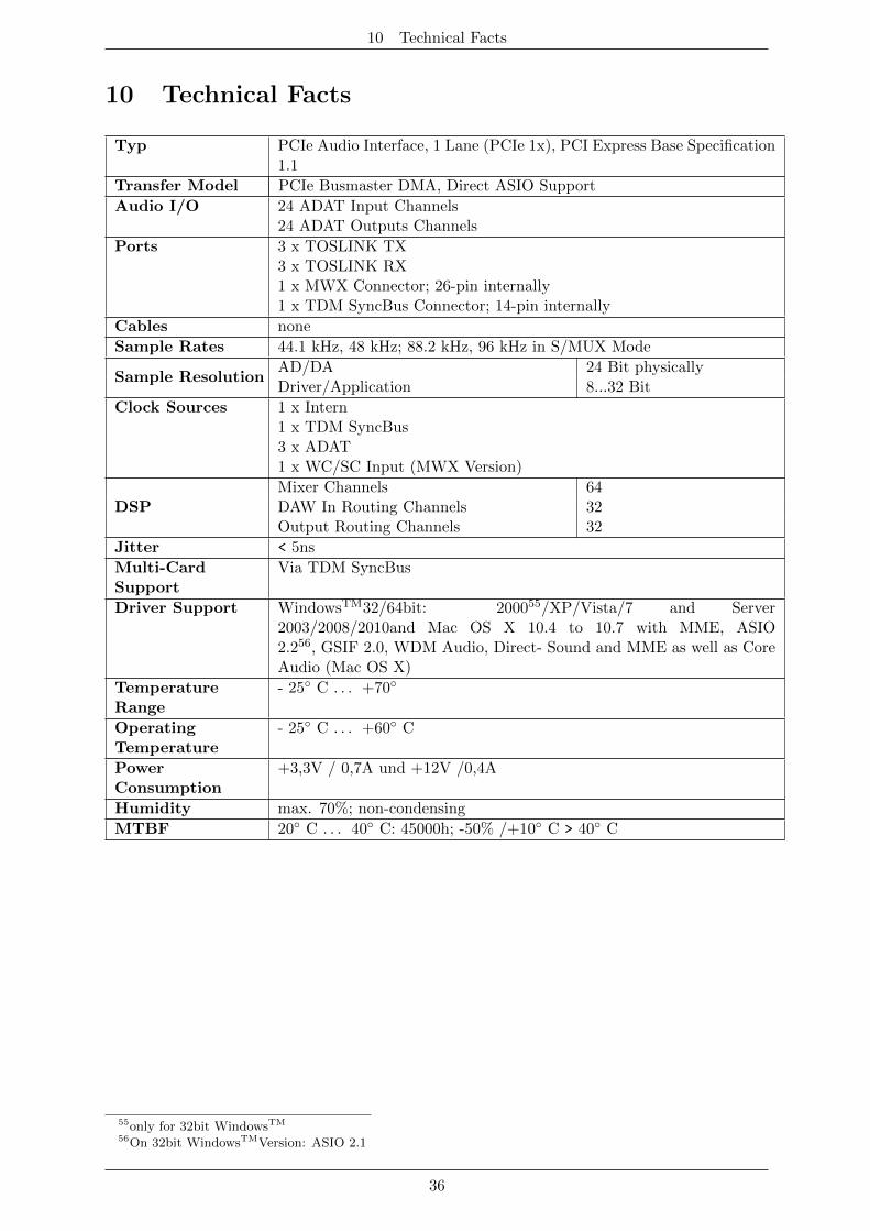
Typ PCIe Audio Interface, 1 Lane (PCIe 1x), PCI Express Base Specification1.1
Transfer Model PCIe Busmaster DMA, Direct ASIO Support
Audio I/O 24 ADAT Input Channels24 ADAT Outputs Channels
Ports 3 x TOSLINK TX3 x TOSLINK RX1 x MWX Connector; 26-pin internally1 x TDM SyncBus Connector; 14-pin internally
Cables none
Sample Rates 44.1 kHz, 48 kHz; 88.2 kHz, 96 kHz in S/MUX Mode
Sample ResolutionAD/DA 24 Bit physicallyDriver/Application 8...32 Bit
Clock Sources 1 x Intern1 x TDM SyncBus3 x ADAT1 x WC/SC Input (MWX Version)
DSPMixer Channels 64DAW In Routing Channels 32Output Routing Channels 32
Jitter < 5ns
Multi-CardSupport
Via TDM SyncBus
Driver Support WindowsTM32/64bit: 200055/XP/Vista/7 and Server2003/2008/2010and Mac OS X 10.4 to 10.7 with MME, ASIO2.256, GSIF 2.0, WDM Audio, Direct- Sound and MME as well as CoreAudio (Mac OS X)
TemperatureRange
- 25◦ C . . . +70◦
OperatingTemperature
- 25◦ C . . . +60◦ C
PowerConsumption
+3,3V / 0,7A und +12V /0,4A
Humidity max. 70%; non-condensing
MTBF 20◦ C . . . 40◦ C: 45000h; -50% /+10◦ C > 40◦ C
55only for 32bit WindowsTM
56On 32bit WindowsTMVersion: ASIO 2.1
36
10 Technical Facts
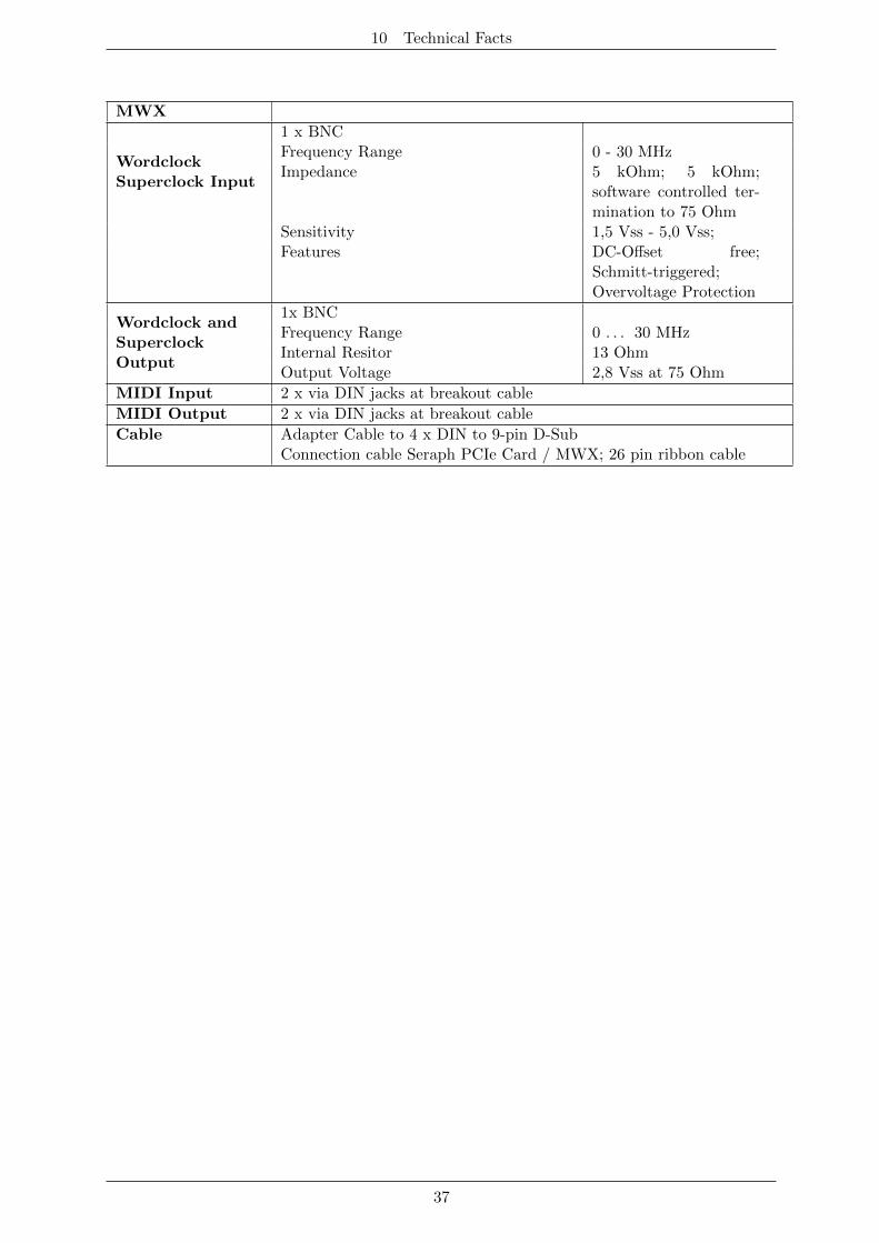
MWX
WordclockSuperclock Input
1 x BNCFrequency Range 0 - 30 MHzImpedance 5 kOhm; 5 kOhm;
software controlled ter-mination to 75 Ohm
Sensitivity 1,5 Vss - 5,0 Vss;Features DC-Offset free;
Schmitt-triggered;Overvoltage Protection
Wordclock andSuperclockOutput
1x BNCFrequency Range 0 . . . 30 MHzInternal Resitor 13 OhmOutput Voltage 2,8 Vss at 75 Ohm
MIDI Input 2 x via DIN jacks at breakout cable
MIDI Output 2 x via DIN jacks at breakout cable
Cable Adapter Cable to 4 x DIN to 9-pin D-SubConnection cable Seraph PCIe Card / MWX; 26 pin ribbon cable
37