Embed Size (px)
Citation preview

GLOBAL ARCHITECTURE
- Lightweight, fl exible cable and electronic modules that operate to a depth of: SeaRay® 300: 300 m — use down to 500 m with restrictions SeaRay® 100: 100 m (smaller diameter cable)- Active sections with distributed electronics.- ASICS and MEMS technology (24 bit, Sigma /Delta)- Designed for redeployable, four-component seismic data acquisition on seabed. - Fully integrated acquisition system.- Flexible architecture: redundant telemetry lines. Data transmission reconfi guration on line failure. - Redundant power (two high voltage rails)- Multi-recorder capabilities (remote control of recorder/buoys)
SeaRay® 428GENERAL
Ahead of the CurveSM
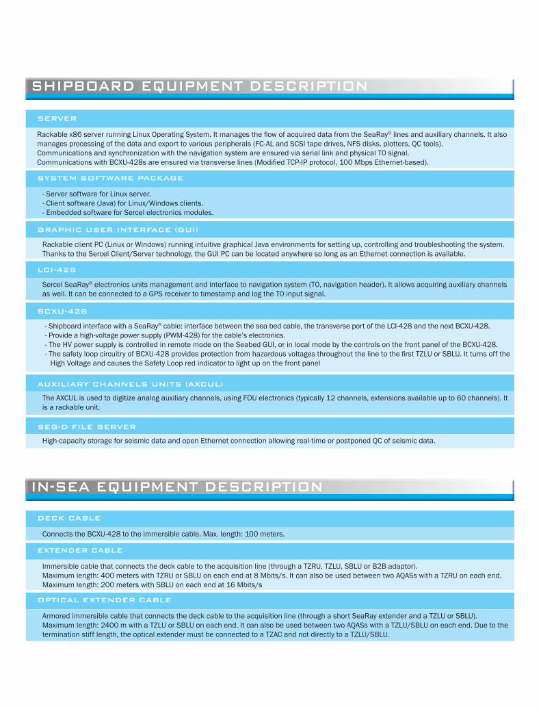
SERVER
Rackable x86 server running Linux Operating System. It manages the fl ow of acquired data from the SeaRay® lines and auxiliary channels. It also manages processing of the data and export to various peripherals (FC-AL and SCSI tape drives, NFS disks, plotters, QC tools).Communications and synchronization with the navigation system are ensured via serial link and physical T0 signal.Communications with BCXU-428s are ensured via transverse lines (Modifi ed TCP-IP protocol, 100 Mbps Ethernet-based).
SYSTEM SOFTWARE PACKAGE
- Server software for Linux server.- Client software (Java) for Linux/Windows clients.- Embedded software for Sercel electronics modules.
GRAPHIC USER INTERFACE (GUI)
Rackable client PC (Linux or Windows) running intuitive graphical Java environments for setting up, controlling and troubleshooting the system.Thanks to the Sercel Client/Server technology, the GUI PC can be located anywhere so long as an Ethernet connection is available.
LCI-428
Sercel SeaRay® electronics units management and interface to navigation system (T0, navigation header). It allows acquiring auxiliary channels as well. It can be connected to a GPS receiver to timestamp and log the T0 input signal.
BCXU-428
- Shipboard interface with a SeaRay® cable: interface between the sea bed cable, the transverse port of the LCI-428 and the next BCXU-428.- Provide a high-voltage power supply (PWM-428) for the cable’s electronics.- The HV power supply is controlled in remote mode on the Seabed GUI, or in local mode by the controls on the front panel of the BCXU-428.- The safety loop circuitry of BCXU-428 provides protection from hazardous voltages throughout the line to the fi rst TZLU or SBLU. It turns off the
High Voltage and causes the Safety Loop red indicator to light up on the front panel
AUXILIARY CHANNELS UNITS (AXCUL)
The AXCUL is used to digitize analog auxiliary channels, using FDU electronics (typically 12 channels, extensions available up to 60 channels). It is a rackable unit.
SEG-D FILE SERVER
High-capacity storage for seismic data and open Ethernet connection allowing real-time or postponed QC of seismic data.
SHIPBOARD EQUIPMENT DESCRIPTION
IN-SEA EQUIPMENT DESCRIPTION
DECK CABLE
Connects the BCXU-428 to the immersible cable. Max. length: 100 meters.
EXTENDER CABLE
Immersible cable that connects the deck cable to the acquisition line (through a TZRU, TZLU, SBLU or B2B adaptor). Maximum length: 400 meters with TZRU or SBLU on each end at 8 Mbits/s. It can also be used between two AQASs with a TZRU on each end. Maximum length: 200 meters with SBLU on each end at 16 Mbits/s
OPTICAL EXTENDER CABLE
Armored immersible cable that connects the deck cable to the acquisition line (through a short SeaRay extender and a TZLU or SBLU). Maximum length: 2400 m with a TZLU or SBLU on each end. It can also be used between two AQASs with a TZLU/SBLU on each end. Due to the termination stiff length, the optical extender must be connected to a TZAC and not directly to a TZLU/SBLU.

TZAC
Extender cable, less than 100meters, that connects the TZLU to the TZRU. Standard length: 25 meters.
TZRU
Long-range repeater unit, required if the length between the BCXU-428 and the TZLU or between AQDSUs exceeds 100 meters.TZRU is not compatible with data rate of 16 Mbits/s.
TZLU
• The TZLU processes the data from the fl atpack channels and controls the path of the data fl ow to the next TZLU through two independent transmission lines providing tolerance to faults.
• It detects and processes communication errors if any. In the event of a disruption or transmission problems on one line it automatically routes the data to the other transmission line.
• The TZLU operates from the 365 VDC voltage conveyed by the cable. It converts that HV voltage into 12 VDC for its own use, and converts the 12VDC into ± 24 V for the fl atpack channels.
• The TZLU manages data rate of 8Mbits/s, and can manage up to 30 receiver points (120 channels).• Note that an odd number of AQAS sections (i. e. even number of B2Bs) is required between two TZLUs.• The safety loop circuitry provides protection from hazardous voltages throughout the acquisition line to the next TZLU. It turns off the High
Voltage and causes the Safety Loop red indicator to light up on the front panel• TZLU is not compatible with 600V or a data rate of 16 Mbits/s.
SBLU
• Same features than TZLU +• The SBLU operates from the 600VDC voltage conveyed by the cable. It converts that HV voltage into 12 VDC for its own use, and converts the
12VDC into ±24 V for the fl atpack channels.• The SBLU manages data rate of 8Mbits/s or 16Mbits/s.• The SBLU includes an equalizer and can be used as a repeater and can replace a TZRU.• Improved leakage measurement.• An odd or even number of sections can be connected between two SBLUs.
AQAS
The Acquisition Active Section (AQAS) is the data-gathering section with fl atpacks spaced equidistantly along the cable. The quantity of AQDSUs on an AQAS must be even. Two types of cables are available:• SeaRay® 300: 300 m— use down to 500 m with restrictions• SeaRay® 100: 100 m (smaller diameter cable)
FLATPACK
4-channel receiver point including: SSH-Hydrophone AQDSU: with 1 FDU (for SSH-Hydrophone) and 3 digital sensors (MEMS).
B2B/EB2B
Back-to-back adapter is used between two adjacent AQASs or extenders.The EB2B is used between two adjacent extenders only.The B2B with mechanical fuse allows safe SeaRay cables connection on recorder vessel. It includes a breakable link which snaps at:• Searay 100 : 7 kN• Searay 300 : 25 kNIt also includes a groove for tow clamp installation.
PACAP
Protective anchoring cap.

Note : All specifi cations below are typical at 25°C
SHIPBOARD EQUIPMENT
SYSTEM CAPABILITIES
Processing capabilities DC offset removal Vertical stack Alternate or simultaneous multi-source operation AQDSU tilt correction
Real-time QC eSQC Pro for data QC eSGA for specifi c trace analysis
Play-back eSQC Pro Plotter
Storage capabilities Tape drives, NASSEG-D fi les are stored temporarily in the SEG-D repository (server storage or external SEG-D fi le server) prior to being transferred to tape or NAS or QC tools, allowing acquisition to continue during taping incident (tape recording fault tolerant), and allowing SEG-D to be annotated with source and receiver QCs.
RECORDING (BASIC CONFIGURATION)
Format 4byte, SEG-D Rev. 1.0 or 2.1 demultiplexed, 32 bit IEEE, code 8058.
Tape media Up to 2 drives, simultaneous and alternated modes. Drive model: 3590 model B, E, H, DLT, LTO IBM 3580, 3592
Ethernet media NFS protocol. (2 disk targets)
Sampling rate 1/4 ms, 1/2 ms, 1ms, 2 ms, 4 ms.
Maximum record length Depends on server and line confi guration. Refer to next chapter.
Maximum number of auxiliary channels 60 analog.
Maximum number of Flatpack receivers 220 RPs with full redundancy (telemetry and high voltage) per line @ 8 Mbits/s with zero dead time 440 RPs without telemetry redundancy(Typical @ 2 ms, depending on signal type and compression ratio)
SPECIFICATIONS
SeaRay line confi guration
SeaRay 428 line confi guration

Configuration(Results are Typical @ 2 ms, depending on
signal type and compression ratio)
Distance betweenRPs (m)
Number of AQDSUsbetween SBLUs
Maximum length
between SBLUs
Maximum Active Line Length (m)
(1)
Quantity of SBLUs
TotalRPs
Zero dead time rate with Telemetry
redundancy(2) & (3)
Zero dead time rate with no
Telemetry redundancy
(4)
HVredundancy
(5)
25m - TZLU – 8 Mbits/s – 365V
Zero dead time with full redundancy 25 30 750 5500 9 220 - - Yes
Zero dead time with HV redundancy only 25 30 750 9750 14 390 77% - Yes
Zero dead time with no redundancy 25 30 750 11000 16 440 100% - No
Maximum length due to HV loss 25 30 750 14500 21 580 164% 32% No
50m - TZLU – 8 Mbits/s – 365V
Zero dead time with full redundancy 50 30 1500 11000 9 220 - - Yes
Zero dead time with HV redundancy only 50 30 1500 14500 11 290 32% - Yes
Maximum length due to HV loss 50 30 1500 21000 15 420 91% - No
25m - SBLU – 8 Mbits/s – 600V
Zero dead time with full redundancy 25 30 750 5500 9 220 - - Yes
Zero dead time with HV redundancy only 25 30 750 11000 16 440 100% - Yes
No zero dead time with HV redundancy only 25 30 750 17250 24 690 214% 57% No
Maximum length due to HV loss 25 30 750 23250 32 930 323% 111% No
50m - SBLU – 8 Mbits/s – 600V
Zero dead time with full redundancy 50 30 1500 11000 9 220 - - Yes
Zero dead time with HV redundancy only 50 30 1500 22000 16 440 100% - Yes
No zero dead time with HV redundancy only 50 30 1500 25500 18 510 132% 16% No
Maximum length due to HV loss 50 30 1500 37500 26 750 241% 70% No
(1) Confi guration between active line and BCXU is: BCXU - Deck cable (50m) + SBLU + Extender (300m) + SBLU + Extender (300m) + SBLU + Extender (300m) + SBLU + TZAC (25m) + Active line(2) Telemetry redundancy = means that system can work with only one telemetry line(3) Zero dead time (%) is calculated as: (Number of RPs/220-1), where 220 is the maximum number of receiver points with zero dead time and telemetry redundancy(4) Zero dead time (%) is calculated as: (Number of RPs/440-1), where 440 is the maximum number of receiver points with zero dead time(5) HV redundancy = means that system can work with only one HV rail
Maximum number of Flatpack receivers 420 RPs with full redundancy (telemetry and high voltage) per line @ 16 Mbits/s (SBLU only) with 590 RPs without telemetry redundancyzero dead time (Typical @ 2 ms, depending on signal type and compression ratio)
Configuration(Results are Typical @ 2 ms, depending on
signal type and compression ratio)
Distance betweenRPs (m)
Number of AQDSUsbetween SBLUs
Maximum length
between SBLUs
Maximum Active Line Length (m)
(1)
Quantity of SBLUs
TotalRPs
Zero dead time rate with Telemetry
redundancy(2) & (3)
Zero dead time rate with no
Telemetry redundancy
(4)
HVredundancy
(5)
25m - SBLU – 16 Mbits/s – 600V
Zero dead time with full redundancy 25 60 1500 10500 8 420 - - Yes
Zero dead time with HV redundancy only 25 60 1500 14750 11 590 40% - Yes
No zero dead time with HV redundancy only 25 60 1500 18000 13 720 71% 22% Yes
Maximum length due to HV loss 25 60 1500 27000 19 1080 157% 83% No
(1) Confi guration between active line and BCXU is: BCXU - Deck cable (50m) + SBLU + Extender (300m) + SBLU + Extender (300m) + SBLU + Extender (300m) + SBLU + TZAC (25m) + Active line(2) Telemetry redundancy = means that system can work with only one telemetry line(3) Zero dead time (%) is calculated as: (Number of RPs/420-1), where 420 is the maximum number of receiver points with zero dead time and telemetry redundancy(4) Zero dead time (%) is calculated as: (Number of RPs/590-1), where 590 is the maximum number of receiver points with zero dead time(5) HV redundancy = means that system can work with only one HV rail

SERVER
Hardware 2U 19” rackable, 86.1 x 486 x 700 (19 x 27.25 x 3.5 in) HP DL 380
Operating system Linux Red Hat ES.
Software Seabed Server Software, performing data computation, storage and handling of local or remote clients.
CLIENT
Computer PC, desktop or laptop, local or remote. HP Z400, 6Go or equivalent
Screens Up to 4 per client
Operating system Linux RedHat WS 32 or 64bits (recommended OS) Windows XP, 7
Software Seabed Client software, performing operator interface and parameters display.
LCI-428
Field units management, up to 8000 channels real time @ 2ms (typical compression ratio: 40%).
Up to 3 LCI-428 can be linked together to handle more channels.
Operating voltage 110-220 VAC, 50/60 Hz
Power consumption 6.7 W
Dimensions (HxWxD) 2U 19” rackable, 86.1 x 483 x 420.7 mm (19 x 16.5 x 3.4 in.)
Weight 4.1 kg (9.0 lbs.)
BCXU-428
Modifi ed TCP-IP protocol, 100 Mbps Ethernet-based, for connection to the LCI
Built-in high-voltage converter (power supply to cable).
High-voltage remote or local operation.
Connection to Deck safety devices (Emergency stop, warning lights).
Connection to the deck cable through a 2-m Deck cable Adaptor.
The safety loop circuitry of BCXU-428 provides protection from hazardous voltages throughout the line to the fi st TZLU or SBLU. It turns off the High Voltage and causes the Safety Loop red indicator to light up on the front panel
Input Voltage 110V/220V AC ±20%.
Frequency 50-60 Hz ±5%.
Power ratings The power rating of the high voltage power supply depends on the selected output voltage.
Output DC voltage Power 600 VDC 1500 W 550 VDC 1375 W 500 VDC 1250 W 450 VDC 1125 W 400 VDC 1000 W 350 VDC 875 W
Output voltage From 100 VDC to 600 VDC. (Must be limited to 365 VDC for compliance with TZLU).
Output Current Max. 2.5 A.
Safety features Current limitation, High Voltage leakage measurement.
Leakage current High Voltage leakage current measurement from -50.0 mA to +50.0 mA @ 1% FS.
Dimensions (HxWxD) 2U 19” rackable, 89 x 482.6 x 580 mm (without rear panel connectors)
Weight 18 kg
Grounding The BCXU-428 must be connected to a protective earth ground.
DECK CABLE
Length: Up to 100m
STORAGE AND OPERATING TEMPERATURE (SHIPBOARD)
Operating +5°C to +40°CStorage -15°C to +55°C

SBLU
50 VDC (±25VDC) power supply for active channels for the two lines.
High Voltage Lines and telemetry switches.
Manages data rate of 8Mbits/s or 16Mbits/s, and can manage up to 30 receiver points (120 channels) or 60 receiver points (240 channels) respectively.
Data routing, and data pre-processing.
The safety loop circuitry provides protection from hazardous voltages throughout the acquisition line to the next SBLU or TZLU. It turns off the High Voltage and causes the Safety Loop red indicator to light up on the front panel.The SBLU includes an equalizer and can be used as a repeater (400m at 8Mbits/s, and 300m at 16Mbits/s).
Maximum input voltage 600 VDC
Connectors 70mm, 28 pins
Maximum outside diameter 104 mm
Overall assembled length (including bend restrictors) 1371 mm
Stiff length (termination + SBLU + termination) 720.5 mm
Weight in air (termination + SBLU + termination) 17.8 kg
Weight in seawater (termination + SBLU + termination) 10.9 kg
Number of bend restrictors per termination 1 brass (nearest the module), 5 plastic + 1 tapered end
TZLU
50 VDC (±25VDC) power supply for active channels for the two lines.
High Voltage Lines and telemetry switches.
Manages data rate of 8Mbits/s, and manage up to 30 receiver points (120 channels).
Data routing, and data pre-processing.
The safety loop circuitry provides protection from hazardous voltages throughout the acquisition line to the next TZLU. It turns off the High Voltage and causes the Safety Loop red indicator to light up on the front panel.
Maximum input voltage: 365 VDC
Connectors: 70mm, 28 pins
Maximum outside diameter (TZLU or TZRU) 150.3 mm
Overall assembled length (including bend restrictors) 1420 mm
Stiff length (termination + TZLU + termination) 769.5 mm
Weight in air (termination + TZLU + termination) 21.0 kg
Weight in seawater (termination + TZLU + termination) 10.9 kg
Number of bend restrictors per termination 1 brass (nearest the module), 5 plastic + 1 tapered end
TZRU
Long-range repeater unit, required if the length between the BCXU-428 and the TZLU or between AQASs exceeds 100 meters.
Power Source 50 VDC from telemetry lines
Dimensions Same as TZLU
IN-SEA UNITS

FLATPACK
The Flatpack cage protects AQDSU canister, SSH-01 hydrophone cylinder and cable takeout.Material Flatpack cage aluminum-bronze articulated bend restrictors glass-fi ber-reinforced plastic
Maximum outside width 174 mm
Maximum outside height 71 mm
Cage length 455 mm
Number of bend restrictors 7 + 1 tapered end link on each side
Overall length with bend restrictors 968 mm
Stiff length 392 mm
Weight in air 14.15 kg
Weight in sea water 10.88 kg
ENVIRONMENT
Storage temperature – 40ºC to + 60ºC
Operating temperature 0°C to +40°C
Deployment/Testing Temperature* 15ºC to + 40ºC
(with degraded performance)
Maximum operating depth SeaRay® 100 100m
Maximum operating depth SeaRay® 300 300m 500m with specifi c handling care
AQAS/EXTENDERS
Extender cables are constructed of varying lengths of lightweight, fl exible SeaRay® bulk cable, from 25 metres to 400 metres long. They have a SeaRay® female cable connector (28-contact circular socket connector) housed in a waterproof cable termination at each end.
Optical extender cables are constructed of varying lengths of armored cable from 400 metres to 2,4 kilometers long. They have a SeaRay® female cable connector (28-contact circular socket connector) housed in a waterproof cable termination at each end. The termination includes the optical/electrical converters.
The AcQuisition Active Section (AQAS) is the data-gathering section with fl atpacks spaced equidistantly along the cable. The quantity of fl atpacks on an AQAS must be even.
User-specifi ed distances between fl atpacks are between 12.5 metres and 55 metres. Standard AQAS confi guration is 10 fl atpacks per cable. Typical lengths are 250 metres and 500 metres. For example, an AQAS with ten fl atpacks 25 metres apart will have a length of 250 metres. An AQAS with ten fl atpacks 50 metres apart will have a length of 500 metres.
Minimum spacing of receiver points 12.5 mMaximum spacing of receiver points up to 60 m
* Tests can be run before deployment on the seabed.

SeaRay® 100
Color yellow
Outside diameter 21.6 mm (over ribs)
Maximum active section length 1800 m
Minimum breaking strength 22 kN
Maximum allowable working load 4.5 kN
Point (local) pressure loading 10 Mpa
Minimum sheave diameter 1.5 m
Weight in air 564 kg/km
Weight in sea water 210 kg/km
Maximum operating depth 100m
SeaRay® 300
Color yellow
Outside diameter 28.5 mm (over ribs)
Maximum active section length 1800 m
Minimum breaking strength 66 kN
Maximum allowable working load 16.5 kN
Point (local) pressure loading 10 Mpa
Minimum sheave diameter 3.0 m
Weight in air 849 kg/km
Weight in sea water 231 kg/km
Maximum operating depth 300m
500m (with specifi c handling care)
OPTICAL EXTENDER
Construction Double armour
Outside diameter 23.0 mm
Maximum length 2,4 kms
Minimum breaking strength 300 kN
Maximum allowable working load 80 kN
Minimum sheave diameter 3m
Weight in air 1700 kg/km
Weight in sea water 1350 kg/km
Maximum operating depth 300m
500m (with specifi c handling care)

GENERAL
Sensor Component 3 omni tilt digital accelerometer and 1 hydrophone
Sample rates** 4,2,1,0.5,0.25 ms
Word Size 24 bits
Offset 0 (digitally zeroed)
High cut fi lter** 0.8 FN (linear or minimum phase)
Stop band attenuation > 120 dB (above Nyquist)
Time Standard True synchronous system
Phase accuracy 20 μsPower consumption Typical (during acquisition): 320mW
Max (during sensor tests): 370mW
DIGITAL ACCELEROMETER CHANNELS
Type Omni tilt DSU-428Full scale 5m/s2Tilt Max Value ± 180°Bandwidth 0 – 400 Hz (up to 1600 Hz with degraded specifi cations)Distortion -90 dBAmplitude Calibration Accuracy ± 0.25%Orthogonality Calibration Accuracy ± 0.25°Noise (10-200Hz) 0.4 μm/s2/√HzSystem dynamic range 120 dB @ 4 msTilt accuracy ± 0.5° @ 20°C
HYDROPHONE CHANNEL
Type FDU-428 Input with charge amplifi erFull scale @ G1600: 1.6 V RMS @ G400: 400 mV RMSNoise (3-200Hz) (typical) @ G1600: 450 nV RMS @ G400: 145 nV RMSBandwidth 3 – 1600 HzInstant dynamic range 124 dBSystem dynamic range 136 dBDistortion -110 dBCMRR 110 dBGain Accuracy <0.1%Phase Accuracy 20 μs
CANISTER
Material Nickel aluminium BronzeOutside diameter of canister 54 mmLength: overall length of canister 203.2 mm length over non-mated connectors 240.1 mm length over mated connectors 300.4 mmWeight in air 1.571 kg
** Bandwidth limited to 400Hz with full specifi cation
SENSORS
AQDSU

SSH HYDROPHONE
All specifi cations apply at ambient pressure and 20ºC. All electrical and acoustic measurements are made with the two internal hydrophone elements combined into an in-phase, parallel circuit. All sensitivity values are free-fi eld voltage sensitivity (FFVS). All specifi cations without tolerance limits denote typical values.
GENERAL
Material polyurethane sleeveFill fl uid Silicone fl uidOutside diameter of cylinder 54 mmLength 154 mmWeight in air 0.405 kgOperating temperature –15ºC to +50ºCStorage temperature –40ºC to +60ºC
ELECTRICAL SPECIFICATION
Lead type 4-conductor cable with an Impulse 4pin 90-degree connectorLead length 140 mmCapacitance 9.6 nF ±15% at 1 V & 1 KHz (@ 20ºC & 1 ATM) (Approx. 0.4% increase per degree C°). 9.6 nF stands for the equivalent capacitance of the two hydrophone elements in parallel connection. The
system’s sensor test reads the average of the capacitance values of the two elements, that is 4.8 nF.
Resistance, lead to lead or lead to case > 100 MΩ @ 10 VDC.
Dissipation factor 0.02 (typical maximum)
PERFORMANCE SPECIFICATION
Voltage sensitivity Hydrophone sensitivity: –204.5 dB re 1 V/μPa (5.96 V/bar) ± 1.5 dB at 20 Hz (@ 20ºC & 1 ATM). System sensitivity (including charge amplifi er): 5.66 V/bar.Voltage sensitivity vs. temperature <1.5 dB change from –10ºC to +40ºC (0.04 dB maximum change per 1ºC)Maximum operating depth 500 m

Sercel - France16 rue de Bel-AirB.P. 30439. 44474 CARQUEFOU CedexTelephone: (33) 2 40 30 11 81Fax: (33) 2 40 30 19 48E-mail: [email protected]. au capital de 2 000 000 € Siège Social: 16 rue de Bel Air 44470 Carquefou. 378.040.497 R.C.S. Nantes Code APE 2651B
Sercel Inc. - USA 17200 Park RowHouston, Texas 77084Telephone: (1) 281 492 6688Fax: (1) 281 579 7505E-mail: [email protected]
www.sercel.com
Printed in France. © Sercel 06/12
Ahead of the CurveSM
Printed on 100% recycled paper using vegetable-oil based ink
Compatibility between SeaRay and SeaRay 428
Software Version <V2.0 >V2.0Transmission rate 8 MHz 16 MHz 8 MHz 16 MHz
TZRU Yes No Yes No
TZLU Yes No Yes No
SBLU No NoYes
Repeater : 400 mYes
Repeater : 300 m
Optical Extender Yes No Yes Yes
Software Version <V2.0 >V2.0BCXU output Voltage 365V 600V 365V 600V
TZRU Yes No Yes Yes
TZLU Yes No Yes No
SBLU No No Yes Yes
Optical Extender Yes No Yes Yes
GPS Accutime Gold Meinberg M300
Software version < V2.0 > V2.0
COMPATIBILITY