Embed Size (px)
Citation preview
Protocol API
sercos Master
V2.1.x.x
Hilscher Gesellschaft für Systemautomation mbH
www.hilscher.com DOC081103API11EN | Revision 11 | English | 2013-09 | Released | Public
Table of Contents 2/390
sercos Master | Protocol API DOC081103API11EN | Revision 11 | English | 2013-09 | Released | Public © Hilscher, 2008-2013
Table of Contents
1 Introduction.............................................................................................................................................6 1.1 About this Document......................................................................................................................6 1.2 List of Revisions .............................................................................................................................6 1.3 Intended Audience .........................................................................................................................7 1.4 System Requirements....................................................................................................................7 1.5 Specifications .................................................................................................................................8
1.5.1 Technical Data .................................................................................................................................. 8 1.6 Terms, Abbreviations and Definitions ............................................................................................9 1.7 References.....................................................................................................................................9 1.8 Legal Notes ..................................................................................................................................10
1.8.1 Copyright ......................................................................................................................................... 10 1.8.2 Important Notes............................................................................................................................... 10 1.8.3 Exclusion of Liability ........................................................................................................................ 11 1.8.4 Export .............................................................................................................................................. 11
2 Fundamentals .......................................................................................................................................12 2.1 General Access Mechanisms on netX Systems ..........................................................................12 2.2 Accessing the Protocol Stack by Programming the AP Task’s Queue........................................13
2.2.1 Getting the Receiver Task Handle of the Process Queue ............................................................... 13 2.2.2 Meaning of Source- and Destination-related Parameters................................................................ 13
2.3 Accessing the Protocol Stack via the Dual Port Memory Interface..............................................14 2.3.1 Communication via Mailboxes......................................................................................................... 14 2.3.2 Using Source and Destination Variables correctly........................................................................... 15 2.3.3 Obtaining useful Information about the Communication Channel.................................................... 18
2.4 Client/Server Mechanism.............................................................................................................20 2.4.1 Application as Client ........................................................................................................................ 20 2.4.2 Application as Server ...................................................................................................................... 21
3 Dual-Port Memory ................................................................................................................................22 3.1 Cyclic Data (Input/Output Data) ...................................................................................................22
3.1.1 Input Process Data.......................................................................................................................... 23 3.1.2 Output Process Data ....................................................................................................................... 23
3.2 Acyclic Data (Mailboxes)..............................................................................................................24 3.2.1 General Structure of Messages or Packets for Non-Cyclic Data Exchange .................................... 25 3.2.2 Status & Error Codes ...................................................................................................................... 28 3.2.3 Differences between System and Channel Mailboxes .................................................................... 28 3.2.4 Send Mailbox................................................................................................................................... 29 3.2.5 Receive Mailbox .............................................................................................................................. 29 3.2.6 Channel Mailboxes (Details of Send and Receive Mailboxes) ........................................................ 29
3.3 Status ...........................................................................................................................................30 3.3.1 Common Status............................................................................................................................... 30 3.3.2 Extended Status .............................................................................................................................. 39
3.4 Control Block................................................................................................................................41
4 Getting started / Configuration ...........................................................................................................42 4.1 Overview about Essential Functionality .......................................................................................42 4.2 Configuration of sercos Master ....................................................................................................42
4.2.1 Using the configuration tool SYCON.net ......................................................................................... 43 4.2.2 Using configuration via packets....................................................................................................... 44 4.2.3 Detailed Description of Master Parameters ..................................................................................... 47
5 Overview................................................................................................................................................50 5.1 Task Structure of the sercos Master Stack ..................................................................................50
5.1.1 General Structure of the sercos Stack............................................................................................. 50 5.2 State Machine (Communication Phases).....................................................................................52
5.2.1 State Transitions ............................................................................................................................. 52 5.2.2 Non real-time Mode (NRT Mode) .................................................................................................... 53 5.2.3 Communication Phase 0 (CP0) ....................................................................................................... 53 5.2.4 Communication Phase 1 (CP1) ....................................................................................................... 53 5.2.5 Communication Phase 2 (CP2) ....................................................................................................... 54 5.2.6 Communication Phase 3 (CP3) ....................................................................................................... 54 5.2.7 Communication Phase 4 (CP4) ....................................................................................................... 54
5.3 SCP Classes ................................................................................................................................55
Table of Contents 3/390
sercos Master | Protocol API DOC081103API11EN | Revision 11 | English | 2013-09 | Released | Public © Hilscher, 2008-2013
5.3.1 SCP_FixCFG / SCP_VarCFG / SCP_RTB (Real-Time Bits) ........................................................... 55 5.3.2 SCP_Sync ....................................................................................................................................... 55 5.3.3 SCP_SysTime ................................................................................................................................. 55 5.3.4 SCP_WD / SCP_WDCon ................................................................................................................ 55 5.3.5 SCP_Diag........................................................................................................................................ 55 5.3.6 SCP_HP (Hot Plug) ......................................................................................................................... 55 5.3.7 SCP_SMP ....................................................................................................................................... 55 5.3.8 SCP_MuX / SCP_ExtMuX (multiplex channel)................................................................................ 56 5.3.9 SCP_SIG / SCP_RTBListProd / SCP_RTBListCons / SCP_RTBWordProd / SCP_RTBWordCons56 5.3.10 SCP_ListSeg ................................................................................................................................... 56 5.3.11 SCP_NRT / SCP_NRTPC............................................................................................................... 56 5.3.12 SCP_SIP ......................................................................................................................................... 56 5.3.13 SCP_TFTP...................................................................................................................................... 56 5.3.14 SCP_Cap ........................................................................................................................................ 56 5.3.15 SCP_SafetyCon .............................................................................................................................. 56 5.3.16 SCP_OvSBasic ............................................................................................................................... 56 5.3.17 SCP_Cyc......................................................................................................................................... 56
5.4 Commonly Used Values in Packets.............................................................................................57 5.4.1 Values for Identifying Communication Phases in Packets............................................................... 57 5.4.2 NRT Reason Codes ........................................................................................................................ 58 5.4.3 Stop Reason Codes For State Change Abort.................................................................................. 59 5.4.4 Bit List Layout for All Slaves Status Representation........................................................................ 61 5.4.5 Stack Mode Flags............................................................................................................................ 62
5.5 Addressing of Slaves in Application Interface..............................................................................63 5.5.1 Addressing Schemes....................................................................................................................... 63 5.5.2 Operation Modes............................................................................................................................. 64
5.6 Procedure Commands .................................................................................................................65 5.6.1 Executing Procedure Commands via Svc Macro Functions ............................................................ 65 5.6.2 Procedure Command Control and Acknowledge Definitions ........................................................... 66 5.6.3 The Procedure Command Change Bit............................................................................................. 67
5.7 Diagnosis......................................................................................................................................68 5.7.1 Slave Diagnostic Information........................................................................................................... 68 5.7.2 Diagnostic Log................................................................................................................................. 68 5.7.3 C1D and C2D .................................................................................................................................. 69 5.7.4 Bus Scan ......................................................................................................................................... 69
5.8 Ring Topology and Ring Healing .................................................................................................70 5.9 Hot Plug (since V2.1.X)................................................................................................................70 5.10 Process Data................................................................................................................................71
5.10.1 Connection Control (C-CON)........................................................................................................... 71 5.11 Process Data Exchange Timing...................................................................................................74
5.11.1 Bus-synchronous Mode................................................................................................................... 74 5.11.2 Free-Run Mode (only available for DPM/SHM) ............................................................................... 76
5.12 NRT Channel Behavior ................................................................................................................77 5.12.1 Routing Behavior............................................................................................................................. 77 5.12.2 Ring Detection................................................................................................................................. 77
5.13 NRT Channel Access on DPM.....................................................................................................78
6 The Application Interface ....................................................................................................................79 6.1 Configuration Data Packets .........................................................................................................80
6.1.1 Auto Configuration Service.............................................................................................................. 80 6.1.2 Process Data Image Layout Configuration ...................................................................................... 85 6.1.3 Connection Control Handling Configuration (since V2.1.X) ............................................................. 86 6.1.4 Parameters used in all Variants....................................................................................................... 88 6.1.5 Parameters used for automatic Configuration of Frame Layout ...................................................... 89 6.1.6 Common Services (all Packet Configuration Variants) .................................................................... 90 6.1.7 Automatic Configuration of Frame Layout with automatic Timing Calculation ............................... 114 6.1.8 Automatic Configuration of Frame Layout with user specified Timing Parameters........................ 117 6.1.9 Usage and Flow Diagram of automatic Configuration Packets...................................................... 119 6.1.10 Packets used for automatic Configuration (AutoCfg) of Frame Layout.......................................... 121 6.1.11 Manual Configuration of Frame Layout and Timing Parameters ................................................... 132 6.1.12 Usage and Flow Diagram of manual Configuration of Frame Layout ............................................ 139 6.1.13 Packets used for manual Configuration......................................................................................... 141 6.1.14 Unload Configuration Service........................................................................................................ 155
6.2 Configuration Information Readout ............................................................................................157 6.2.1 Get CP3/CP4 Timing Information Service ..................................................................................... 157 6.2.2 Get Configured List Of Slaves Service (since version V2.1.X) ...................................................... 161 6.2.3 Get Configured Slave Identification Data Service (since version V2.1.X)...................................... 163 6.2.4 Get Configured Connections Of Slave Service (since version V2.1.X).......................................... 165
Table of Contents 4/390
sercos Master | Protocol API DOC081103API11EN | Revision 11 | English | 2013-09 | Released | Public © Hilscher, 2008-2013
6.2.5 Get Connection Information Service.............................................................................................. 167 6.2.6 Get Configured Connection Layout Service (since version V2.1.X) .............................................. 170
6.3 Phase Control ............................................................................................................................173 6.3.1 Architecture of Communication Phase Control.............................................................................. 173 6.3.2 Services......................................................................................................................................... 174 6.3.3 Legacy Services ............................................................................................................................ 178
6.4 Status Indications.......................................................................................................................190 6.4.1 Registration and Deregistration of Status Indications.................................................................... 190 6.4.2 Common Indications...................................................................................................................... 197 6.4.3 Legacy Indications......................................................................................................................... 228
6.5 Diagnostic Log ...........................................................................................................................240 6.5.1 Diagnostic Log Entry Format ......................................................................................................... 240 6.5.2 Reading and Clearing.................................................................................................................... 256 6.5.3 Diagnostic Log Indication Handling ............................................................................................... 260
6.6 Slave Identification Services ......................................................................................................268 6.6.1 Get Detected sercos Addresses Service ....................................................................................... 268
6.7 Controlling the C-DEV Ident Request Bit ...................................................................................270 6.7.1 Set Ident Request Bit Service........................................................................................................ 270 6.7.2 Clear Ident Request Bit Service .................................................................................................... 272
6.8 Service Channel Access ............................................................................................................274 6.8.1 Changes in Packets since V2.1.X ................................................................................................. 274 6.8.2 Priority Level System..................................................................................................................... 274 6.8.3 Data Representation in the Data Part of Packets .......................................................................... 275 6.8.4 Common Parameters of Service Channel Services ...................................................................... 278 6.8.5 Macro SVC Services ..................................................................................................................... 280 6.8.6 Macro SVC Services (Extended Length, since V2.1.X) ................................................................. 299 6.8.7 Atomic SVC Services .................................................................................................................... 305 6.8.8 Atomic SVC Services (Extended Length, since V2.1.X) ................................................................ 324 6.8.9 Fragmentation Flow Charts ........................................................................................................... 330
6.9 Hot Plug (since V2.1.X)..............................................................................................................332 6.9.1 Hot Plug Indication ........................................................................................................................ 332 6.9.2 Hot Plug Error Acknowledgement Service..................................................................................... 332
6.10 Retrieval of Slave Diagnostic Information ..................................................................................334 6.10.1 Relation: Slave Diagnostic Handles and Slave Addresses............................................................ 334 6.10.2 Provided Lists................................................................................................................................ 334 6.10.3 Usage of Slave Diagnostic Information Packets............................................................................ 335 6.10.4 Structure of per Slave Diagnostic Data.......................................................................................... 336 6.10.5 Packets.......................................................................................................................................... 337
6.11 Bus Scan....................................................................................................................................341 6.11.1 Packet Parameter ulSlaveFlags ............................................................................................... 341 6.11.2 Generic Bus Scan ......................................................................................................................... 341 6.11.3 Legacy Bus Scan .......................................................................................................................... 345
6.12 Manual Ring Healing Control .....................................................................................................351 6.12.1 Set Ring Healing to Manual Service.............................................................................................. 351 6.12.2 Set Ring Healing to Automatic Service.......................................................................................... 353 6.12.3 Request Manual Ring Healing Service.......................................................................................... 355 6.12.4 Get Ring Status Service (since V2.1.X)......................................................................................... 357
6.13 NRT Promiscuous Control .........................................................................................................359 6.13.1 Enable NRT Promiscuous Service ................................................................................................ 359 6.13.2 Disable NRT Promiscuous Service ............................................................................................... 361
7 Status/Error Codes Overview............................................................................................................363
8 Appendix .............................................................................................................................................374 8.1 LED Definitions ..........................................................................................................................374 8.2 Device Status and Device Control .............................................................................................375
8.2.1 Device Status (S-DEV) .................................................................................................................. 375 8.2.2 Device Control (C-DEV) ................................................................................................................ 376
8.3 Object Dictionary........................................................................................................................377 8.3.1 General Access Procedure............................................................................................................ 377 8.3.2 IDN Structure................................................................................................................................. 377 8.3.3 Name............................................................................................................................................. 378 8.3.4 Attribute ......................................................................................................................................... 379 8.3.5 Unit ................................................................................................................................................ 380 8.3.6 Minimum / Maximum ..................................................................................................................... 380 8.3.7 Data............................................................................................................................................... 381 8.3.8 sercos Service Channel Error Codes ............................................................................................ 382
8.4 List of Tables..............................................................................................................................384

Table of Contents 5/390
sercos Master | Protocol API DOC081103API11EN | Revision 11 | English | 2013-09 | Released | Public © Hilscher, 2008-2013
8.5 List of Figures.............................................................................................................................389 8.6 Contacts .....................................................................................................................................390
Introduction 6/390
sercos Master | Protocol API DOC081103API11EN | Revision 11 | English | 2013-09 | Released | Public © Hilscher, 2008-2013
1 Introduction
1.1 About this Document
This manual describes the Application interface of the sercos-Master Stack. The goal of this manual is to support the developer during the integration process of the given Stack into a user Application.
This sercos Master Stack is based on the Hilscher Task Layer Reference Programming Model. It is a description of how to program a Task in general, which is defined as a combination of appropriate functions belonging to the same type of protocol layer. It furthermore defines of how different Tasks have to communicate with each other in order to exchange their layer information in between. The Reference Model is commonly used by all programmers at Hilscher and shall be used by you as well when writing your Application Task on top of the Stack.
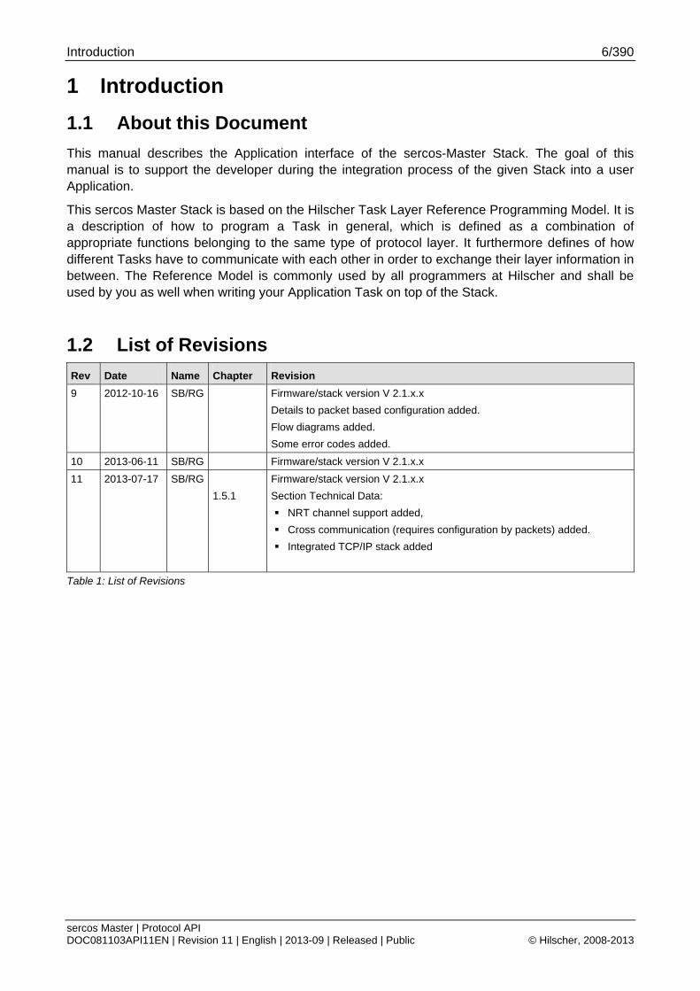
1.2 List of Revisions
Rev Date Name Chapter Revision
9 2012-10-16 SB/RG Firmware/stack version V 2.1.x.x
Details to packet based configuration added.
Flow diagrams added.
Some error codes added.
10 2013-06-11 SB/RG Firmware/stack version V 2.1.x.x
11 2013-07-17 SB/RG
1.5.1
Firmware/stack version V 2.1.x.x
Section Technical Data:
NRT channel support added,
Cross communication (requires configuration by packets) added.
Integrated TCP/IP stack added
Table 1: List of Revisions
Introduction 7/390
sercos Master | Protocol API DOC081103API11EN | Revision 11 | English | 2013-09 | Released | Public © Hilscher, 2008-2013
1.3 Intended Audience
This manual is suitable for software developers with the following background:
Knowledge of the programming language C
Knowledge of the use of the real-time operating system rcX
Knowledge of the Hilscher Task Layer Reference Mode
Knowledge of sercos
1.4 System Requirements
This software package has the following system requirements:
netX-Chip as CPU hardware platform
operating system for task scheduling required
operating system: rcX
Introduction 8/390
sercos Master | Protocol API DOC081103API11EN | Revision 11 | English | 2013-09 | Released | Public © Hilscher, 2008-2013
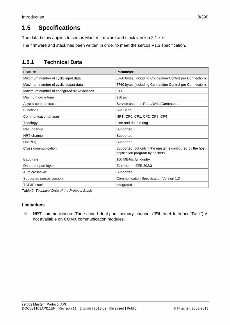
1.5 Specifications
The data below applies to sercos Master firmware and stack version 2.1.x.x.
The firmware and stack has been written in order to meet the sercos V1.3 specification.
1.5.1 Technical Data
Feature Parameter
Maximum number of cyclic input data 5760 bytes (including Connection Control per Connection)
Maximum number of cyclic output data 5760 bytes (including Connection Control per Connection)
Maximum number of configured slave devices 511
Minimum cycle time 250 µs
Acyclic communication Service channel: Read/Write/Commands
Functions Bus Scan
Communication phases NRT, CP0, CP1, CP2, CP3, CP4
Topology Line and double ring
Redundancy Supported
NRT channel Supported
Hot Plug Supported
Cross communication Supported, but only if the master is configured by the host application program by packets.
Baud rate 100 MBit/s, full duplex
Data transport layer Ethernet II, IEEE 802.3
Auto crossover Supported
Supported sercos version Communication Specification Version 1.3
TCP/IP stack Integrated
Table 2: Technical Data of the Protocol Stack
Limitations
NRT communication: The second dual-port memory channel (“Ethernet Interface Task”) is not available on COMX communication modules.
Introduction 9/390
sercos Master | Protocol API DOC081103API11EN | Revision 11 | English | 2013-09 | Released | Public © Hilscher, 2008-2013
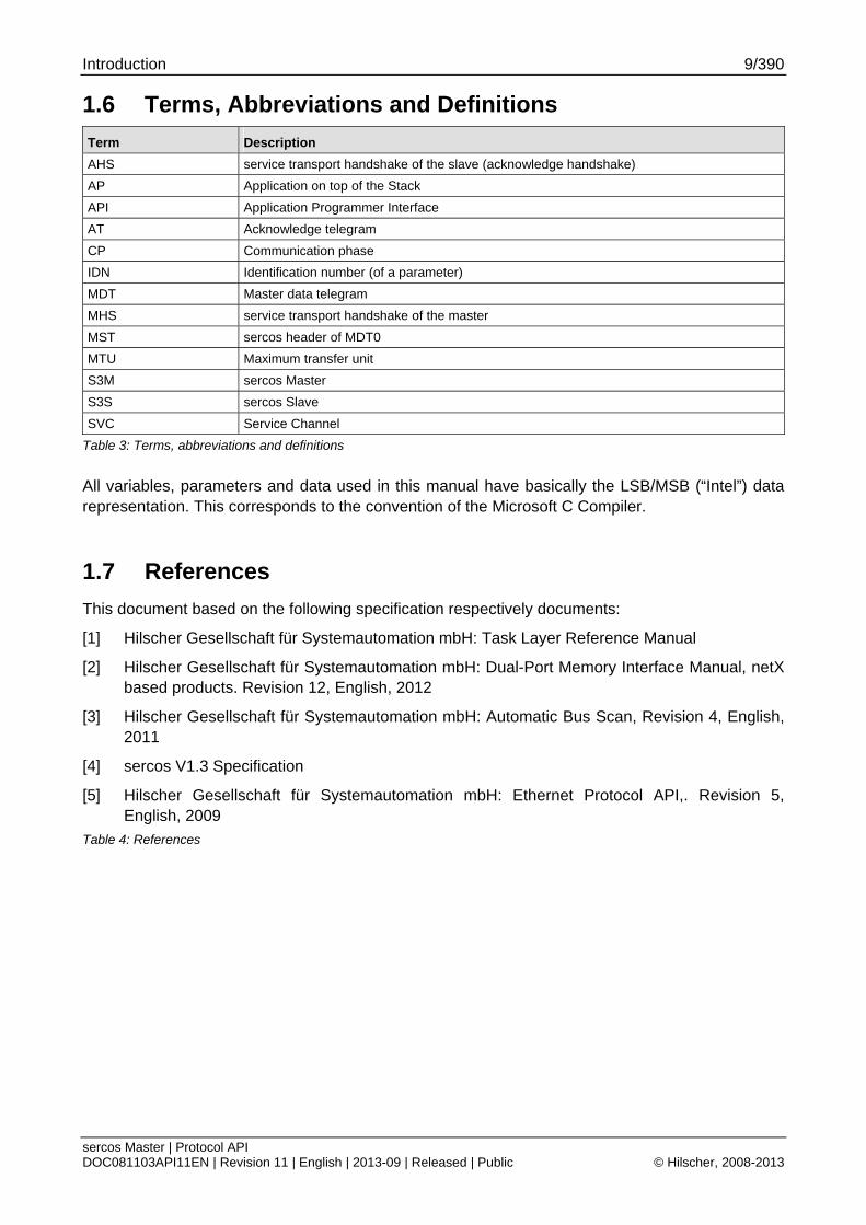
1.6 Terms, Abbreviations and Definitions
Term Description
AHS service transport handshake of the slave (acknowledge handshake)
AP Application on top of the Stack
API Application Programmer Interface
AT Acknowledge telegram
CP Communication phase
IDN Identification number (of a parameter)
MDT Master data telegram
MHS service transport handshake of the master
MST sercos header of MDT0
MTU Maximum transfer unit
S3M sercos Master
S3S sercos Slave
SVC Service Channel
Table 3: Terms, abbreviations and definitions
All variables, parameters and data used in this manual have basically the LSB/MSB (“Intel”) data representation. This corresponds to the convention of the Microsoft C Compiler.
1.7 References
This document based on the following specification respectively documents:
[1] Hilscher Gesellschaft für Systemautomation mbH: Task Layer Reference Manual
[2] Hilscher Gesellschaft für Systemautomation mbH: Dual-Port Memory Interface Manual, netX based products. Revision 12, English, 2012
[3] Hilscher Gesellschaft für Systemautomation mbH: Automatic Bus Scan, Revision 4, English, 2011
[4] sercos V1.3 Specification
[5] Hilscher Gesellschaft für Systemautomation mbH: Ethernet Protocol API,. Revision 5, English, 2009
Table 4: References
Introduction 10/390
sercos Master | Protocol API DOC081103API11EN | Revision 11 | English | 2013-09 | Released | Public © Hilscher, 2008-2013
1.8 Legal Notes
1.8.1 Copyright © 2008-2013 Hilscher Gesellschaft für Systemautomation mbH
All rights reserved.
The images, photographs and texts in the accompanying material (user manual, accompanying texts, documentation, etc.) are protected by German and international copyright law as well as international trade and protection provisions. You are not authorized to duplicate these in whole or in part using technical or mechanical methods (printing, photocopying or other methods), to manipulate or transfer using electronic systems without prior written consent. You are not permitted to make changes to copyright notices, markings, trademarks or ownership declarations. The included diagrams do not take the patent situation into account. The company names and product descriptions included in this document may be trademarks or brands of the respective owners and may be trademarked or patented. Any form of further use requires the explicit consent of the respective rights owner.
1.8.2 Important Notes
The user manual, accompanying texts and the documentation were created for the use of the products by qualified experts, however, errors cannot be ruled out. For this reason, no guarantee can be made and neither juristic responsibility for erroneous information nor any liability can be assumed. Descriptions, accompanying texts and documentation included in the user manual do not present a guarantee nor any information about proper use as stipulated in the contract or a warranted feature. It cannot be ruled out that the user manual, the accompanying texts and the documentation do not correspond exactly to the described features, standards or other data of the delivered product. No warranty or guarantee regarding the correctness or accuracy of the information is assumed.
We reserve the right to change our products and their specification as well as related user manuals, accompanying texts and documentation at all times and without advance notice, without obligation to report the change. Changes will be included in future manuals and do not constitute any obligations. There is no entitlement to revisions of delivered documents. The manual delivered with the product applies.
Hilscher Gesellschaft für Systemautomation mbH is not liable under any circumstances for direct, indirect, incidental or follow-on damage or loss of earnings resulting from the use of the information contained in this publication.
Introduction 11/390
sercos Master | Protocol API DOC081103API11EN | Revision 11 | English | 2013-09 | Released | Public © Hilscher, 2008-2013
1.8.3 Exclusion of Liability
The software was produced and tested with utmost care by Hilscher Gesellschaft für Systemautomation mbH and is made available as is. No warranty can be assumed for the performance and flawlessness of the software for all usage conditions and cases and for the results produced when utilized by the user. Liability for any damages that may result from the use of the hardware or software or related documents, is limited to cases of intent or grossly negligent violation of significant contractual obligations. Indemnity claims for the violation of significant contractual obligations are limited to damages that are foreseeable and typical for this type of contract.
It is strictly prohibited to use the software in the following areas:
for military purposes or in weapon systems;
for the design, construction, maintenance or operation of nuclear facilities;
in air traffic control systems, air traffic or air traffic communication systems;
in life support systems;
in systems in which failures in the software could lead to personal injury or injuries leading to death.
We inform you that the software was not developed for use in dangerous environments requiring fail-proof control mechanisms. Use of the software in such an environment occurs at your own risk. No liability is assumed for damages or losses due to unauthorized use.
1.8.4 Export
The delivered product (including the technical data) is subject to export or import laws as well as the associated regulations of different counters, in particular those of Germany and the USA. The software may not be exported to countries where this is prohibited by the United States Export Administration Act and its additional provisions. You are obligated to comply with the regulations at your personal responsibility. We wish to inform you that you may require permission from state authorities to export, re-export or import the product.
Fundamentals 12/390
sercos Master | Protocol API DOC081103API11EN | Revision 11 | English | 2013-09 | Released | Public © Hilscher, 2008-2013
2 Fundamentals
2.1 General Access Mechanisms on netX Systems
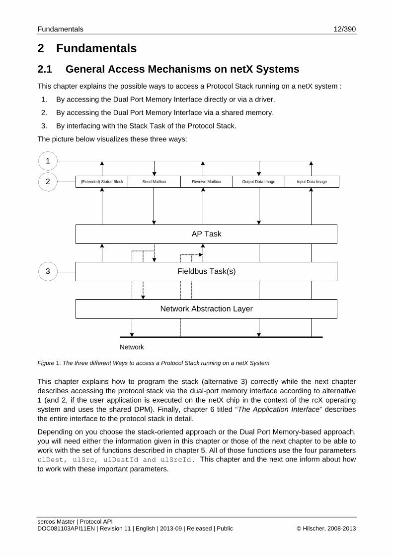
This chapter explains the possible ways to access a Protocol Stack running on a netX system :
1. By accessing the Dual Port Memory Interface directly or via a driver.
2. By accessing the Dual Port Memory Interface via a shared memory.
3. By interfacing with the Stack Task of the Protocol Stack.
The picture below visualizes these three ways:
(Extended) Status Block Send Mailbox Reveive Mailbox Output Data Image Input Data Image
Network Abstraction Layer
Fieldbus Task(s)
Network
AP Task
1
3
2
Figure 1: The three different Ways to access a Protocol Stack running on a netX System
This chapter explains how to program the stack (alternative 3) correctly while the next chapter describes accessing the protocol stack via the dual-port memory interface according to alternative 1 (and 2, if the user application is executed on the netX chip in the context of the rcX operating system and uses the shared DPM). Finally, chapter 6 titled “The Application Interface” describes the entire interface to the protocol stack in detail.
Depending on you choose the stack-oriented approach or the Dual Port Memory-based approach, you will need either the information given in this chapter or those of the next chapter to be able to work with the set of functions described in chapter 5. All of those functions use the four parameters ulDest, ulSrc, ulDestId and ulSrcId. This chapter and the next one inform about how to work with these important parameters.

Fundamentals 13/390
sercos Master | Protocol API DOC081103API11EN | Revision 11 | English | 2013-09 | Released | Public © Hilscher, 2008-2013
2.2 Accessing the Protocol Stack by Programming the AP Task’s Queue
In general, programming the AP task or the stack has to be performed according to the rules explained in the Hilscher Task Layer Reference Manual. There you can also find more information about the variables discussed in the following.
2.2.1 Getting the Receiver Task Handle of the Process Queue
To get the handle of the process queue of the CP-Task the Macro TLR_QUE_IDENTIFY() needs to be used. This macro delivers a pointer to the handle of the intended queue to be accessed (which is returned within the third parameter, phQue), if you provide it with the name of the queue (and an instance of your own task). The correct ASCII-queue names for accessing the CP-Task, which you have to use as current value for the first parameter (pszIdn), is
ASCII Queue name Description
"QUE_S3M_CP” Name of the CP-Task process queue
Table 5: Names of Queues in the sercos Master Firmware
The returned handle has to be used as value ulDest in all initiator packets the AP-Task intends to send to the CP-Task. This handle is the same handle that has to be used in conjunction with the macros like TLR_QUE_SENDPACKET_FIFO/LIFO() for sending a packet to the respective task.
Note: The CP-Task provides a common access point to all master tasks when the AP-Task is not used (since V2.1.X).
2.2.2 Meaning of Source- and Destination-related Parameters The meaning of the source- and destination-related parameters is explained in the following table:
Variable Meaning
ulDest Application mailbox used for confirmation
ulSrc Queue handle returned by TLR_QUE_IDENTIFY() as described above.
ulSrcId Used for addressing at a lower level
Table 6: Meaning of Source- and Destination-related Parameters.
For more information about programming the AP task’s stack queue, please refer to the Hilscher Task Layer Reference Model Manual. Especially the following sections might be of interest in this context:
1. Chapter 7 “Queue-Packets”
2. Section 10.1.9 “Queuing Mechanism”
Fundamentals 14/390
sercos Master | Protocol API DOC081103API11EN | Revision 11 | English | 2013-09 | Released | Public © Hilscher, 2008-2013
2.3 Accessing the Protocol Stack via the Dual Port Memory Interface
This chapter defines the application interface of the sercos Master Stack.
2.3.1 Communication via Mailboxes
The mailbox of each communication channel has two areas that are used for non-cyclic message transfer to and from the netX.
Send Mailbox Packet transfer from host system to netX firmware
Receive Mailbox Packet transfer from netX firmware to host system
For more details about acyclic data transfer via mailboxes, see section 3.2. “Acyclic Data (Mailboxes)” in this context, is described in detail in section 3.2.1 “General Structure of Messages or Packets for Non-Cyclic Data Exchange” while the possible codes that may appear are listed in section 3.2.2. “Status & Error Codes”.
Further, this section concentrates on correct addressing the mailboxes.
Fundamentals 15/390
sercos Master | Protocol API DOC081103API11EN | Revision 11 | English | 2013-09 | Released | Public © Hilscher, 2008-2013
2.3.2 Using Source and Destination Variables correctly
2.3.2.1 How to use ulDest for Addressing rcX and the netX Protocol Stack by the System and Channel Mailbox
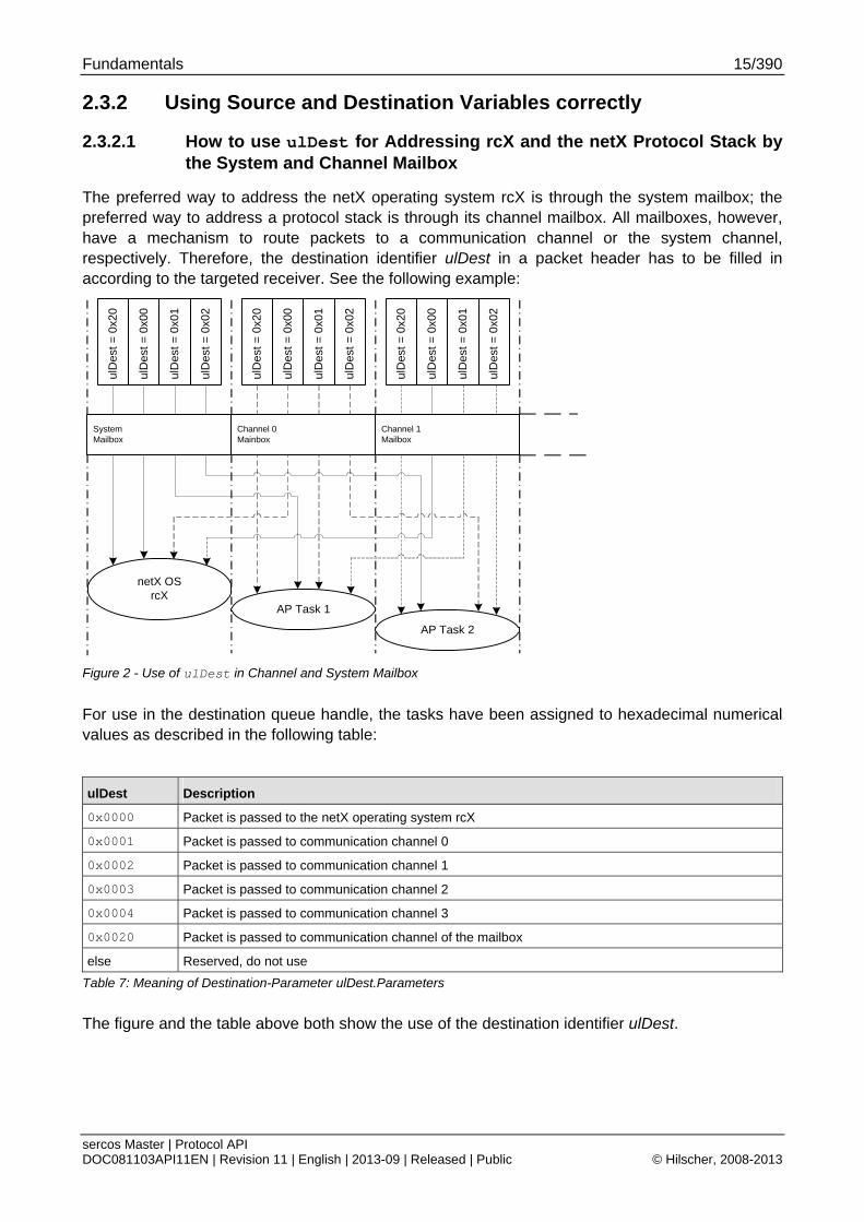
The preferred way to address the netX operating system rcX is through the system mailbox; the preferred way to address a protocol stack is through its channel mailbox. All mailboxes, however, have a mechanism to route packets to a communication channel or the system channel, respectively. Therefore, the destination identifier ulDest in a packet header has to be filled in according to the targeted receiver. See the following example:
netX OSrcX
AP Task 1
AP Task 2
ulD
est
= 0
x00
ulD
est
= 0
x01
ulD
est
= 0
x02
ulD
est
= 0
x20
ulD
est
= 0
x00
ulD
est
= 0
x01
ulD
est
= 0
x02
ulD
est
= 0
x20
ulD
est
= 0
x00
ulD
est
= 0
x01
ulD
est
= 0
x02
ulD
est
= 0
x20
SystemMailbox
Channel 1Mailbox
Channel 0Mainbox
Figure 2 - Use of ulDest in Channel and System Mailbox
For use in the destination queue handle, the tasks have been assigned to hexadecimal numerical values as described in the following table:
ulDest Description
0x0000 Packet is passed to the netX operating system rcX
0x0001 Packet is passed to communication channel 0
0x0002 Packet is passed to communication channel 1
0x0003 Packet is passed to communication channel 2
0x0004 Packet is passed to communication channel 3
0x0020 Packet is passed to communication channel of the mailbox
else Reserved, do not use
Table 7: Meaning of Destination-Parameter ulDest.Parameters
The figure and the table above both show the use of the destination identifier ulDest.
Fundamentals 16/390
sercos Master | Protocol API DOC081103API11EN | Revision 11 | English | 2013-09 | Released | Public © Hilscher, 2008-2013
A remark on the special channel identifier 0x0020 (= Channel Token). The Channel Token is valid for any mailbox. That way the application uses the same identifier for all packets without actually knowing which mailbox or communication channel is applied. The packet stays 'local'. The system mailbox is a little bit different, because it is used to communicate to the netX operating system rcX. The rcX has its own range of valid commands codes and differs from a communication channel.
Unless there is a reply packet, the netX operating system returns it to the same mailbox the request packet went through. Consequently, the host application has to return its reply packet to the mailbox the request was received from.
2.3.2.2 How to use ulSrc and ulSrcId
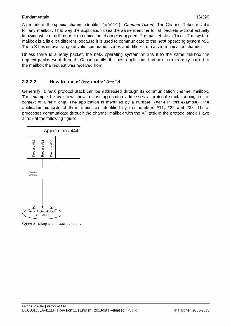
Generally, a netX protocol stack can be addressed through its communication channel mailbox. The example below shows how a host application addresses a protocol stack running in the context of a netX chip. The application is identified by a number (#444 in this example). The application consists of three processes identified by the numbers #11, #22 and #33. These processes communicate through the channel mailbox with the AP task of the protocol stack. Have a look at the following figure:
Application #444
netX Protocol stackAP Task 1
Pro
cess
#2
2
Pro
cess
#3
3
Pro
cess
#1
1
ChannelMailbox
Figure 3 - Using ulSrc and ulSrcId
Fundamentals 17/390
sercos Master | Protocol API DOC081103API11EN | Revision 11 | English | 2013-09 | Released | Public © Hilscher, 2008-2013
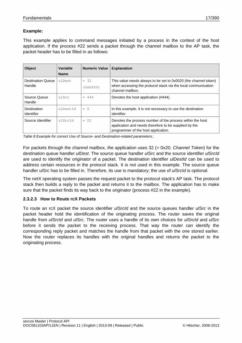
Example:
This example applies to command messages initiated by a process in the context of the host application. If the process #22 sends a packet through the channel mailbox to the AP task, the packet header has to be filled in as follows:
Object Variable
Name
Numeric Value Explanation
Destination Queue Handle
ulDest = 32
(0x0020)
This value needs always to be set to 0x0020 (the channel token) when accessing the protocol stack via the local communication channel mailbox.
Source Queue Handle
ulSrc = 444 Denotes the host application (#444).
Destination Identifier
ulDestId = 0 In this example, it is not necessary to use the destination identifier.
Source Identifier ulSrcId = 22 Denotes the process number of the process within the host application and needs therefore to be supplied by the programmer of the host application.
Table 8 Example for correct Use of Source- and Destination-related parameters.:
For packets through the channel mailbox, the application uses 32 (= 0x20, Channel Token) for the destination queue handler ulDest. The source queue handler ulSrc and the source identifier ulSrcId are used to identify the originator of a packet. The destination identifier ulDestId can be used to address certain resources in the protocol stack. It is not used in this example. The source queue handler ulSrc has to be filled in. Therefore, its use is mandatory; the use of ulSrcId is optional.
The netX operating system passes the request packet to the protocol stack's AP task. The protocol stack then builds a reply to the packet and returns it to the mailbox. The application has to make sure that the packet finds its way back to the originator (process #22 in the example).
2.3.2.3 How to Route rcX Packets
To route an rcX packet the source identifier ulSrcId and the source queues handler ulSrc in the packet header hold the identification of the originating process. The router saves the original handle from ulSrcId and ulSrc. The router uses a handle of its own choices for ulSrcId and ulSrc before it sends the packet to the receiving process. That way the router can identify the corresponding reply packet and matches the handle from that packet with the one stored earlier. Now the router replaces its handles with the original handles and returns the packet to the originating process.
Fundamentals 18/390
sercos Master | Protocol API DOC081103API11EN | Revision 11 | English | 2013-09 | Released | Public © Hilscher, 2008-2013
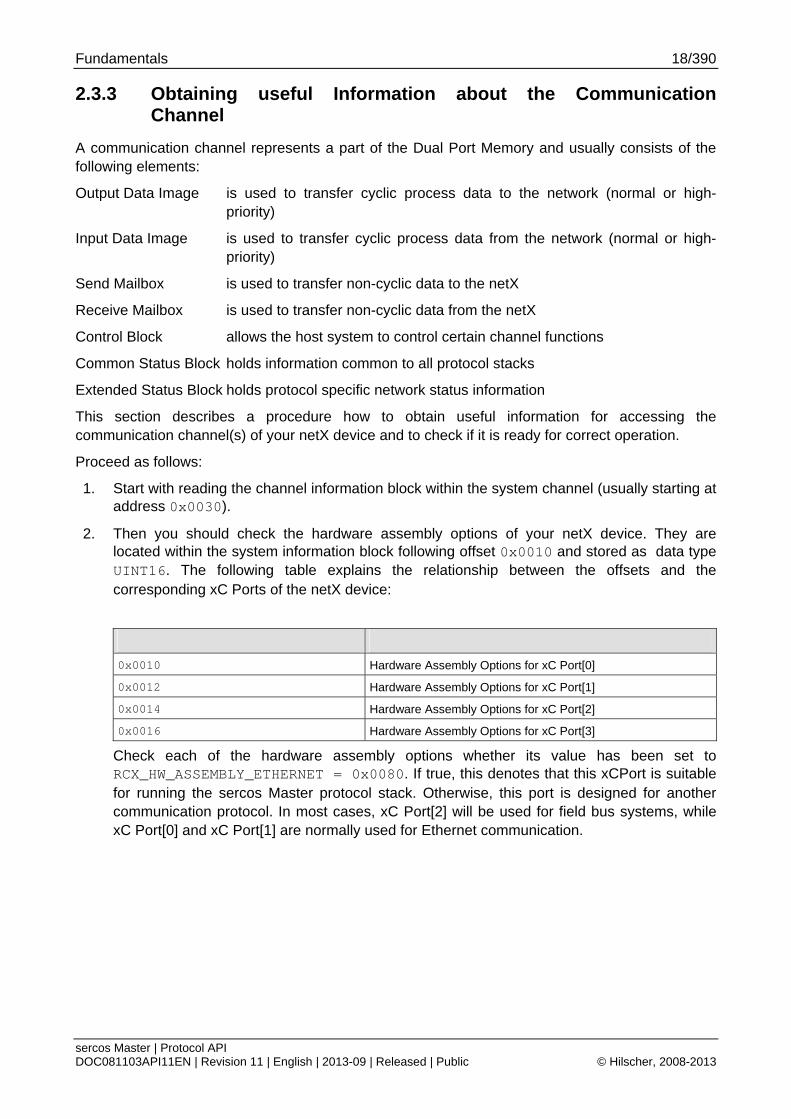
2.3.3 Obtaining useful Information about the Communication Channel
A communication channel represents a part of the Dual Port Memory and usually consists of the following elements:
Output Data Image is used to transfer cyclic process data to the network (normal or high-priority)
Input Data Image is used to transfer cyclic process data from the network (normal or high-priority)
Send Mailbox is used to transfer non-cyclic data to the netX
Receive Mailbox is used to transfer non-cyclic data from the netX
Control Block allows the host system to control certain channel functions
Common Status Block holds information common to all protocol stacks
Extended Status Block holds protocol specific network status information
This section describes a procedure how to obtain useful information for accessing the communication channel(s) of your netX device and to check if it is ready for correct operation.
Proceed as follows:
1. Start with reading the channel information block within the system channel (usually starting at address 0x0030).
2. Then you should check the hardware assembly options of your netX device. They are located within the system information block following offset 0x0010 and stored as data type UINT16. The following table explains the relationship between the offsets and the corresponding xC Ports of the netX device:
0x0010 Hardware Assembly Options for xC Port[0]
0x0012 Hardware Assembly Options for xC Port[1]
0x0014 Hardware Assembly Options for xC Port[2]
0x0016 Hardware Assembly Options for xC Port[3]
Check each of the hardware assembly options whether its value has been set to RCX_HW_ASSEMBLY_ETHERNET = 0x0080. If true, this denotes that this xCPort is suitable for running the sercos Master protocol stack. Otherwise, this port is designed for another communication protocol. In most cases, xC Port[2] will be used for field bus systems, while xC Port[0] and xC Port[1] are normally used for Ethernet communication.
Fundamentals 19/390
sercos Master | Protocol API DOC081103API11EN | Revision 11 | English | 2013-09 | Released | Public © Hilscher, 2008-2013
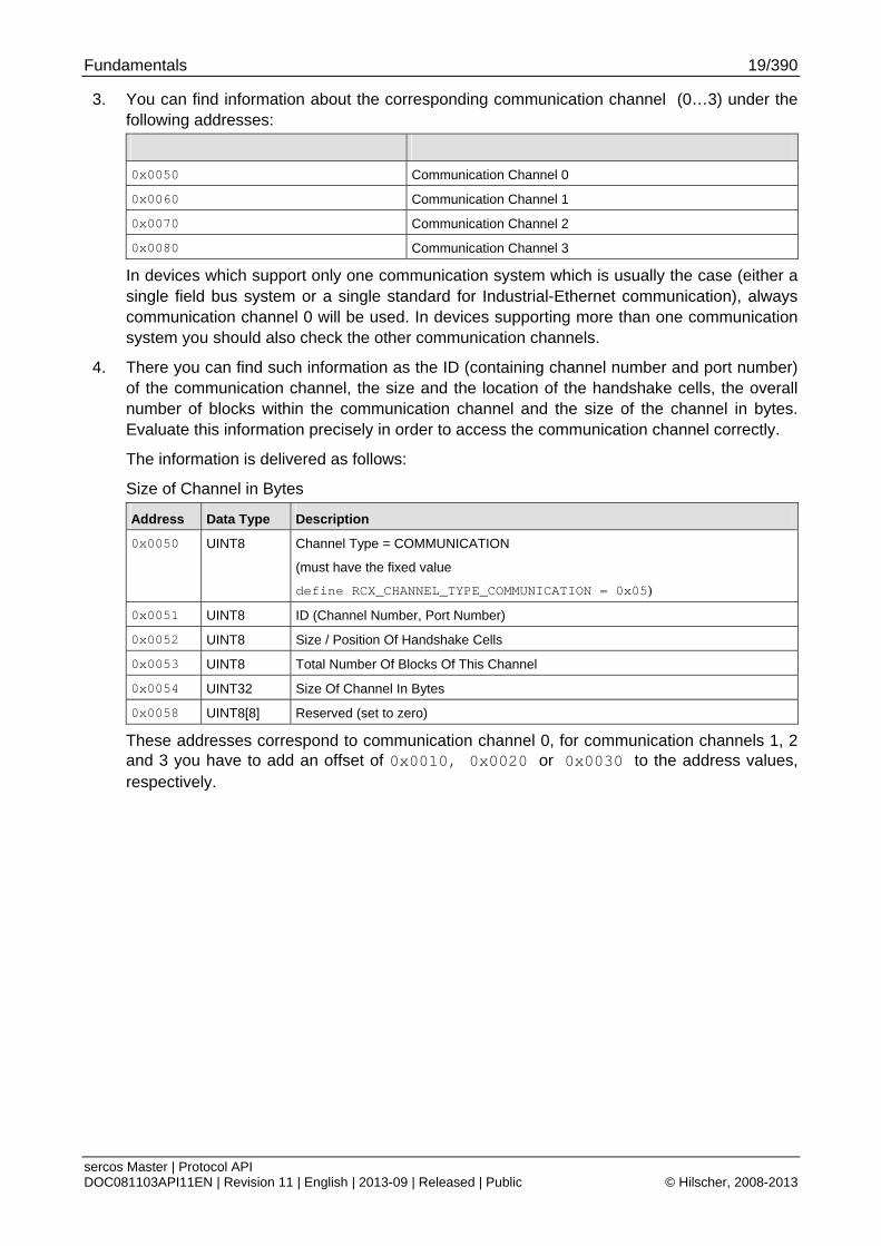
3. You can find information about the corresponding communication channel (0…3) under the following addresses:
0x0050 Communication Channel 0
0x0060 Communication Channel 1
0x0070 Communication Channel 2
0x0080 Communication Channel 3
In devices which support only one communication system which is usually the case (either a single field bus system or a single standard for Industrial-Ethernet communication), always communication channel 0 will be used. In devices supporting more than one communication system you should also check the other communication channels.
4. There you can find such information as the ID (containing channel number and port number) of the communication channel, the size and the location of the handshake cells, the overall number of blocks within the communication channel and the size of the channel in bytes. Evaluate this information precisely in order to access the communication channel correctly.
The information is delivered as follows:
Size of Channel in Bytes
Address Data Type Description
0x0050 UINT8 Channel Type = COMMUNICATION
(must have the fixed value
define RCX_CHANNEL_TYPE_COMMUNICATION = 0x05)
0x0051 UINT8 ID (Channel Number, Port Number)
0x0052 UINT8 Size / Position Of Handshake Cells
0x0053 UINT8 Total Number Of Blocks Of This Channel
0x0054 UINT32 Size Of Channel In Bytes
0x0058 UINT8[8] Reserved (set to zero)
These addresses correspond to communication channel 0, for communication channels 1, 2 and 3 you have to add an offset of 0x0010, 0x0020 or 0x0030 to the address values, respectively.
Fundamentals 20/390
sercos Master | Protocol API DOC081103API11EN | Revision 11 | English | 2013-09 | Released | Public © Hilscher, 2008-2013
2.4 Client/Server Mechanism
2.4.1 Application as Client
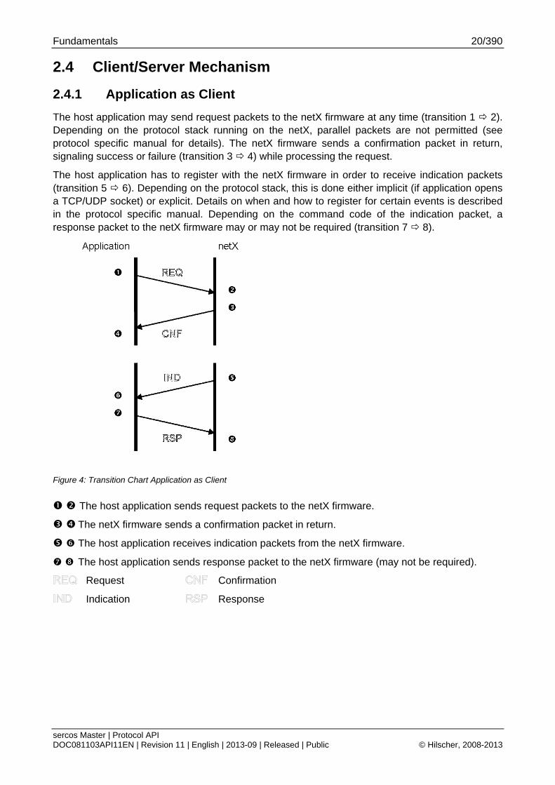
The host application may send request packets to the netX firmware at any time (transition 1 2). Depending on the protocol stack running on the netX, parallel packets are not permitted (see protocol specific manual for details). The netX firmware sends a confirmation packet in return, signaling success or failure (transition 3 4) while processing the request.
The host application has to register with the netX firmware in order to receive indication packets (transition 5 6). Depending on the protocol stack, this is done either implicit (if application opens a TCP/UDP socket) or explicit. Details on when and how to register for certain events is described in the protocol specific manual. Depending on the command code of the indication packet, a response packet to the netX firmware may or may not be required (transition 7 8).
Figure 4: Transition Chart Application as Client
The host application sends request packets to the netX firmware.
The netX firmware sends a confirmation packet in return.
The host application receives indication packets from the netX firmware.
The host application sends response packet to the netX firmware (may not be required).
Request Confirmation
Indication Response
Fundamentals 21/390
sercos Master | Protocol API DOC081103API11EN | Revision 11 | English | 2013-09 | Released | Public © Hilscher, 2008-2013
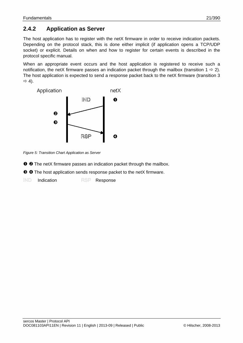
2.4.2 Application as Server
The host application has to register with the netX firmware in order to receive indication packets. Depending on the protocol stack, this is done either implicit (if application opens a TCP/UDP socket) or explicit. Details on when and how to register for certain events is described in the protocol specific manual.
When an appropriate event occurs and the host application is registered to receive such a notification, the netX firmware passes an indication packet through the mailbox (transition 1 2). The host application is expected to send a response packet back to the netX firmware (transition 3 4).
Figure 5: Transition Chart Application as Server
The netX firmware passes an indication packet through the mailbox.
The host application sends response packet to the netX firmware.
Indication Response
Dual-Port Memory 22/390
sercos Master | Protocol API DOC081103API11EN | Revision 11 | English | 2013-09 | Released | Public © Hilscher, 2008-2013
3 Dual-Port Memory All data in the dual-port memory is structured in blocks. According to their functions, these blocks use different data transfer mechanisms. For example, data transfer through mailboxes uses a synchronized handshake mechanism between host system and netX firmware. The same is true for IO data images, when a buffered handshake mode is configured. Other blocks, like the status block, are read by the host application and use no synchronization mechanism.
Types of blocks in the dual-port memory are outlined below:
Mailbox transfer non-cyclic messages or packages with a header for routing information
Data Area holds the process image for cyclic I/O data or user defined data structures
Control Block is used to signal application related state to the netX firmware
Status Block holds information regarding the current network state
Change of State collection of flags that initiate execution of certain commands or signal a change of state
3.1 Cyclic Data (Input/Output Data)
The input block holds the process data image received from the network whereas the output block holds data sent to the network
Process data transfer through the data blocks can be synchronized by using a handshake mechanism (configurable). If in uncontrolled mode, the protocol stack updates the process data in the input and output data image in the dual-port memory for each valid bus cycle. No handshake bits are evaluated and no buffers are used. The application can read or write process data at any given time without obeying the synchronization mechanism otherwise carried out via handshake location. This transfer mechanism is the simplest method of transferring process data between the protocol stack and the application. This mode can only guarantee data consistency over a byte.
For the controlled / buffered mode, the protocol stack updates the process data in the internal input buffer for each valid bus cycle. Each IO block uses handshake bits for access synchronization. Input and output data block handshake operates independently from each other. When the application toggles the input handshake bit, the protocol stack copies the data from the internal buffer into the input data image of the dual-port memory. Now the application can copy data from the dual-port memory and then give control back to the protocol stack by toggling the appropriate input handshake bit. When the application/driver toggles the output handshake bit, the protocol stack copies the data from the output data image of the dual-port memory into the internal buffer. From there the data is transferred to the network. The protocol stack toggles the handshake bits back, indicating to the application that the transfer is finished and a new data exchange cycle may start. This mode guarantees data consistency over both input and output area.
Dual-Port Memory 23/390
sercos Master | Protocol API DOC081103API11EN | Revision 11 | English | 2013-09 | Released | Public © Hilscher, 2008-2013
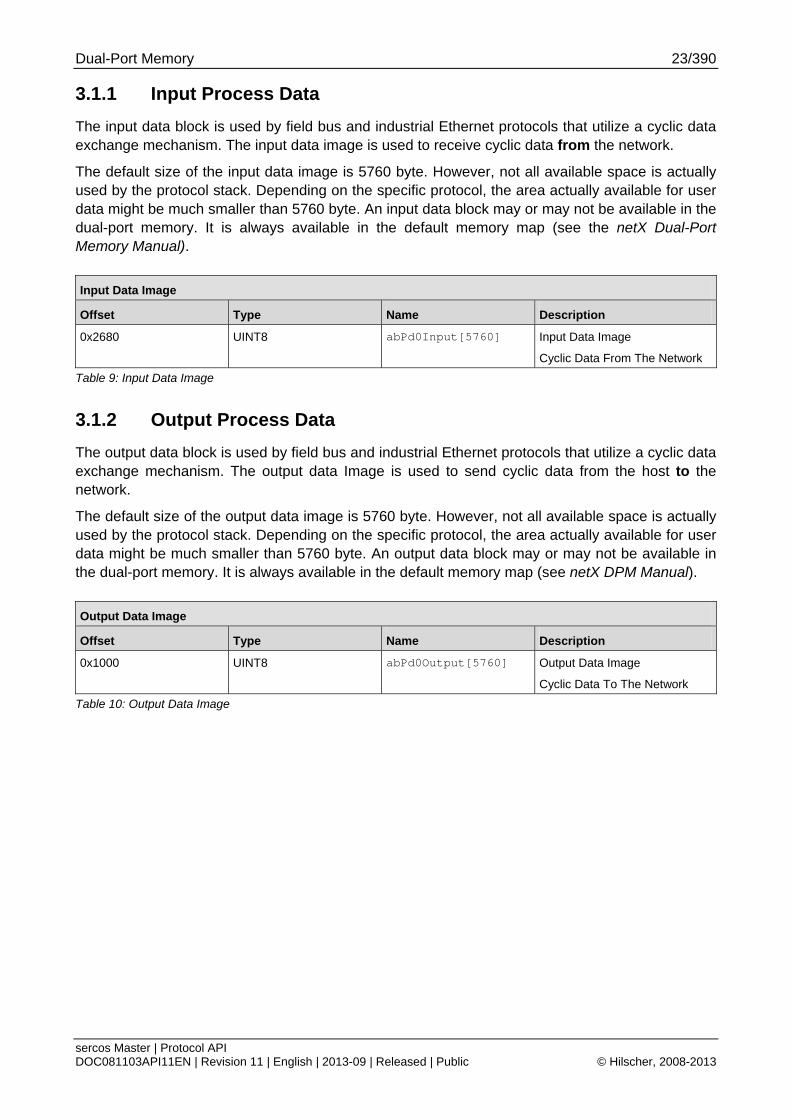
3.1.1 Input Process Data
The input data block is used by field bus and industrial Ethernet protocols that utilize a cyclic data exchange mechanism. The input data image is used to receive cyclic data from the network.
The default size of the input data image is 5760 byte. However, not all available space is actually used by the protocol stack. Depending on the specific protocol, the area actually available for user data might be much smaller than 5760 byte. An input data block may or may not be available in the dual-port memory. It is always available in the default memory map (see the netX Dual-Port Memory Manual).
Input Data Image
Offset Type Name Description
0x2680
UINT8 abPd0Input[5760] Input Data Image
Cyclic Data From The Network
Table 9: Input Data Image
3.1.2 Output Process Data
The output data block is used by field bus and industrial Ethernet protocols that utilize a cyclic data exchange mechanism. The output data Image is used to send cyclic data from the host to the network.
The default size of the output data image is 5760 byte. However, not all available space is actually used by the protocol stack. Depending on the specific protocol, the area actually available for user data might be much smaller than 5760 byte. An output data block may or may not be available in the dual-port memory. It is always available in the default memory map (see netX DPM Manual).
Output Data Image
Offset Type Name Description
0x1000 UINT8 abPd0Output[5760] Output Data Image
Cyclic Data To The Network
Table 10: Output Data Image
Dual-Port Memory 24/390
sercos Master | Protocol API DOC081103API11EN | Revision 11 | English | 2013-09 | Released | Public © Hilscher, 2008-2013
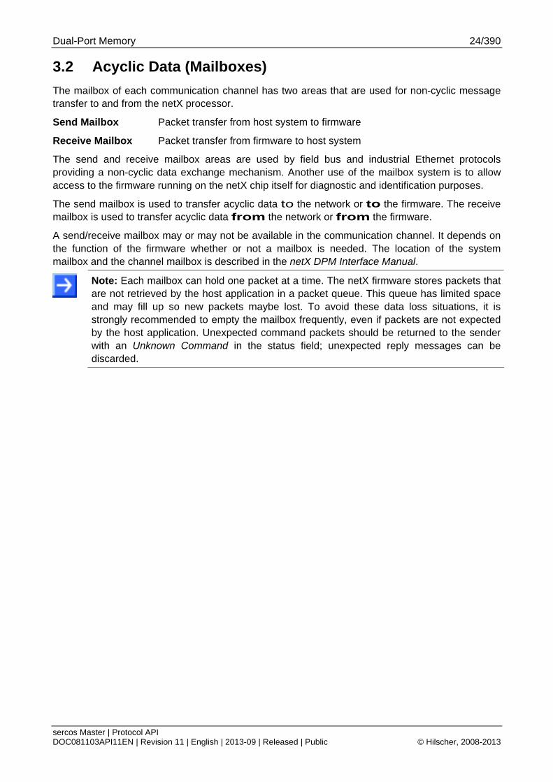
3.2 Acyclic Data (Mailboxes)
The mailbox of each communication channel has two areas that are used for non-cyclic message transfer to and from the netX processor.
Send Mailbox Packet transfer from host system to firmware
Receive Mailbox Packet transfer from firmware to host system
The send and receive mailbox areas are used by field bus and industrial Ethernet protocols providing a non-cyclic data exchange mechanism. Another use of the mailbox system is to allow access to the firmware running on the netX chip itself for diagnostic and identification purposes.
The send mailbox is used to transfer acyclic data to the network or to the firmware. The receive mailbox is used to transfer acyclic data from the network or from the firmware.
A send/receive mailbox may or may not be available in the communication channel. It depends on the function of the firmware whether or not a mailbox is needed. The location of the system mailbox and the channel mailbox is described in the netX DPM Interface Manual.
Note: Each mailbox can hold one packet at a time. The netX firmware stores packets that are not retrieved by the host application in a packet queue. This queue has limited space and may fill up so new packets maybe lost. To avoid these data loss situations, it is strongly recommended to empty the mailbox frequently, even if packets are not expected by the host application. Unexpected command packets should be returned to the sender with an Unknown Command in the status field; unexpected reply messages can be discarded.
Dual-Port Memory 25/390
sercos Master | Protocol API DOC081103API11EN | Revision 11 | English | 2013-09 | Released | Public © Hilscher, 2008-2013
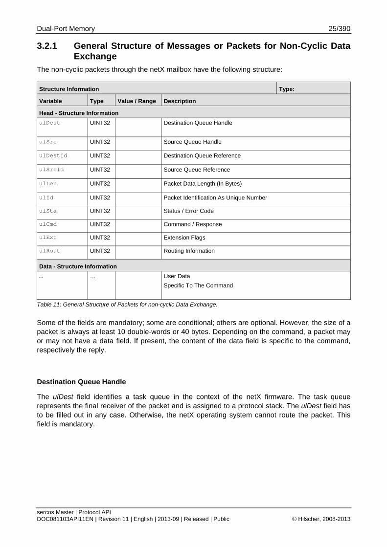
3.2.1 General Structure of Messages or Packets for Non-Cyclic Data Exchange
The non-cyclic packets through the netX mailbox have the following structure:
Structure Information Type:
Variable Type Value / Range Description
Head - Structure Information
ulDest UINT32 Destination Queue Handle
ulSrc UINT32 Source Queue Handle
ulDestId UINT32 Destination Queue Reference
ulSrcId UINT32 Source Queue Reference
ulLen UINT32 Packet Data Length (In Bytes)
ulId UINT32 Packet Identification As Unique Number
ulSta UINT32 Status / Error Code
ulCmd UINT32 Command / Response
ulExt UINT32 Extension Flags
ulRout UINT32 Routing Information
Data - Structure Information
… … User Data
Specific To The Command
Table 11: General Structure of Packets for non-cyclic Data Exchange.
Some of the fields are mandatory; some are conditional; others are optional. However, the size of a packet is always at least 10 double-words or 40 bytes. Depending on the command, a packet may or may not have a data field. If present, the content of the data field is specific to the command, respectively the reply.
Destination Queue Handle
The ulDest field identifies a task queue in the context of the netX firmware. The task queue represents the final receiver of the packet and is assigned to a protocol stack. The ulDest field has to be filled out in any case. Otherwise, the netX operating system cannot route the packet. This field is mandatory.
Dual-Port Memory 26/390
sercos Master | Protocol API DOC081103API11EN | Revision 11 | English | 2013-09 | Released | Public © Hilscher, 2008-2013
Source Queue Handle
The ulSrc field identifies the sender of the packet. In the context of the netX firmware (inter-task communication) this field holds the identifier of the sending task. Usually, a driver uses this field for its own handle, but it can hold any handle of the sending process. Using this field is mandatory. The receiving task does not evaluate this field and passes it back unchanged to the originator of the packet.
Destination Identifier
The ulDestId field identifies the destination of an unsolicited packet from the netX firmware to the host system. It can hold any handle that helps to identify the receiver. Therefore, its use is mandatory for unsolicited packets. The receiver of unsolicited packets has to register for this.
Source Identifier
The ulSrcId field identifies the originator of a packet. This field is used by a host application, which passes a packet from an external process to an internal netX task. The ulSrcId field holds the handle of the external process. When netX operating system returns the packet, the application can identify the packet and returns it to the originating process. The receiving task on the netX does not evaluate this field and passes it back unchanged. For inter-task communication, this field is not used.
Length of Data Field
The ulLen field holds the size of the data field in bytes. It defines the total size of the packet’s payload that follows the packet’s header. The size of the header is not included in ulLen. So the total size of a packet is the size from ulLen plus the size of packet’s header. Depending on the command, a data field may or may not be present in a packet. If no data field is included, the length field is set to zero.
Identifier
The ulId field is used to identify a specific packet among others of the same kind. That way the application or driver can match a specific reply or confirmation packet to a previous request packet.
The receiving task does not change this field and passes it back to the originator of the packet. Its use is optional in most of the cases. However, it is mandatory for sequenced packets.
Example: Downloading big amounts of data that does not fit into a single packet. For a sequence of packets the identifier field is incremented by one for every new packet.
Status / Error Code
The ulSta field is used in response or confirmation packets. It informs the originator of the packet about success or failure of the execution of the command. The field may be also used to hold status information in a request packet.
Dual-Port Memory 27/390
sercos Master | Protocol API DOC081103API11EN | Revision 11 | English | 2013-09 | Released | Public © Hilscher, 2008-2013
Command / Response
The ulCmd field holds the command code or the response code, respectively. The command/response is specific to the receiving task. If a task is not able to execute certain commands, it will return the packet with an error indication. A command is always even (the least significant bit is zero). In the response packet, the command code is incremented by one indicating a confirmation to the request packet.
Extension Flags
The extension field ulExt is used for controlling packets that are sent in a sequenced manner. The extension field indicates the first, last or a packet of a sequence. If sequencing is not required, the extension field is not used and set to zero.
Routing Information
The ulRout field is used internally by the netX firmware only. It has no meaning to a driver type application and therefore set to zero.
User Data Field
This field contains data related to the command specified in ulCmd field. Depending on the command, a packet may or may not have a data field. The length of the data field is given in the ulLen field.
Dual-Port Memory 28/390
sercos Master | Protocol API DOC081103API11EN | Revision 11 | English | 2013-09 | Released | Public © Hilscher, 2008-2013
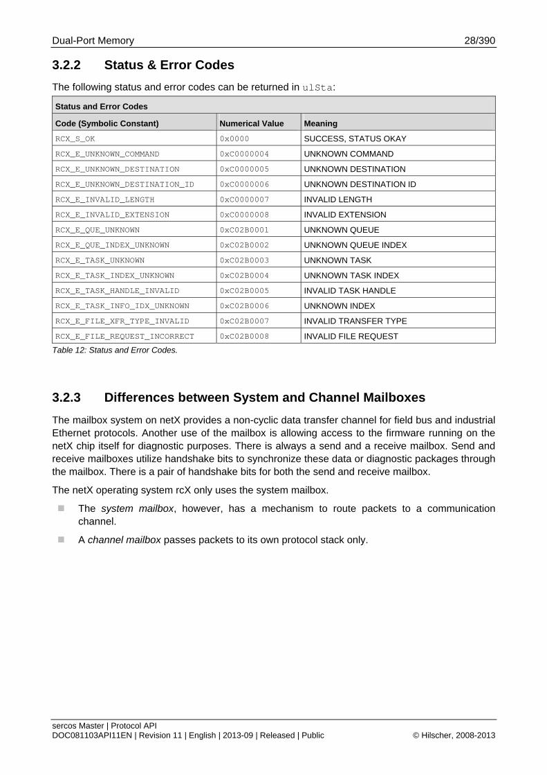
3.2.2 Status & Error Codes
The following status and error codes can be returned in ulSta:
Status and Error Codes
Code (Symbolic Constant) Numerical Value Meaning
RCX_S_OK 0x0000 SUCCESS, STATUS OKAY
RCX_E_UNKNOWN_COMMAND 0xC0000004 UNKNOWN COMMAND
RCX_E_UNKNOWN_DESTINATION 0xC0000005 UNKNOWN DESTINATION
RCX_E_UNKNOWN_DESTINATION_ID 0xC0000006 UNKNOWN DESTINATION ID
RCX_E_INVALID_LENGTH 0xC0000007 INVALID LENGTH
RCX_E_INVALID_EXTENSION 0xC0000008 INVALID EXTENSION
RCX_E_QUE_UNKNOWN 0xC02B0001 UNKNOWN QUEUE
RCX_E_QUE_INDEX_UNKNOWN 0xC02B0002 UNKNOWN QUEUE INDEX
RCX_E_TASK_UNKNOWN 0xC02B0003 UNKNOWN TASK
RCX_E_TASK_INDEX_UNKNOWN 0xC02B0004 UNKNOWN TASK INDEX
RCX_E_TASK_HANDLE_INVALID 0xC02B0005 INVALID TASK HANDLE
RCX_E_TASK_INFO_IDX_UNKNOWN 0xC02B0006 UNKNOWN INDEX
RCX_E_FILE_XFR_TYPE_INVALID 0xC02B0007 INVALID TRANSFER TYPE
RCX_E_FILE_REQUEST_INCORRECT 0xC02B0008 INVALID FILE REQUEST
Table 12: Status and Error Codes.
3.2.3 Differences between System and Channel Mailboxes
The mailbox system on netX provides a non-cyclic data transfer channel for field bus and industrial Ethernet protocols. Another use of the mailbox is allowing access to the firmware running on the netX chip itself for diagnostic purposes. There is always a send and a receive mailbox. Send and receive mailboxes utilize handshake bits to synchronize these data or diagnostic packages through the mailbox. There is a pair of handshake bits for both the send and receive mailbox.
The netX operating system rcX only uses the system mailbox.
The system mailbox, however, has a mechanism to route packets to a communication channel.
A channel mailbox passes packets to its own protocol stack only.
Dual-Port Memory 29/390
sercos Master | Protocol API DOC081103API11EN | Revision 11 | English | 2013-09 | Released | Public © Hilscher, 2008-2013
3.2.4 Send Mailbox
The send mailbox area is used by protocols utilizing a non-cyclic data exchange mechanism. Another use of the mailbox system is to provide access to the firmware running on the netX chip itself. The send mailbox is used to transfer non-cyclic data to the network or to the protocol stack.
The size is 1596 bytes for the send mailbox in the default memory layout. The mailbox is accompanied by counters that hold the number of packages that can be accepted.
3.2.5 Receive Mailbox
The receive mailbox area is used by protocols utilizing a non-cyclic data exchange mechanism. Another use of the mailbox system is to provide access to the firmware running on the netX chip itself. The receive mailbox is used to transfer non-cyclic data from the network or from the protocol stack.
The size is 1596 bytes for the receive mailbox in the default memory layout. The mailbox is accompanied by counters that hold the number of waiting packages (for the receive mailbox).
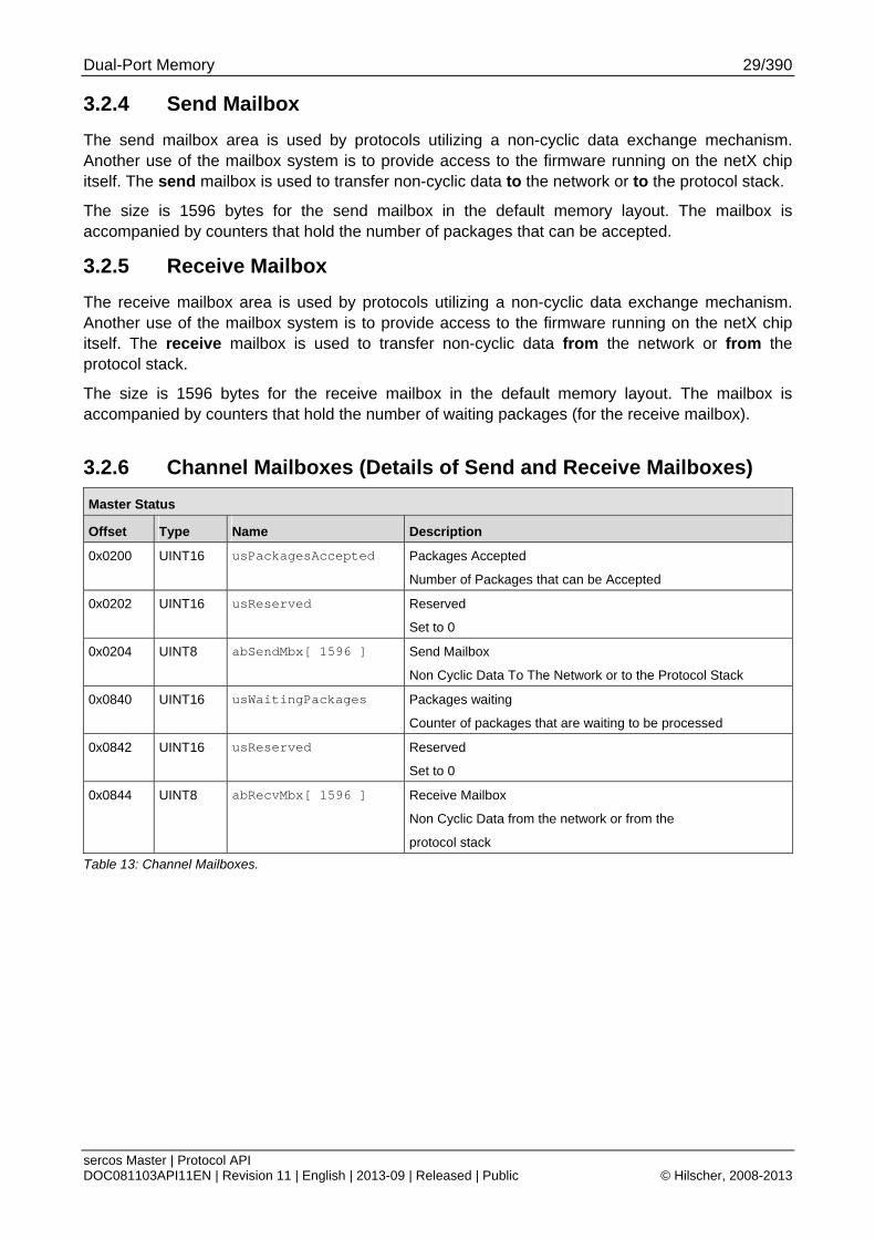
3.2.6 Channel Mailboxes (Details of Send and Receive Mailboxes)
Master Status
Offset Type Name Description
0x0200 UINT16 usPackagesAccepted Packages Accepted
Number of Packages that can be Accepted
0x0202 UINT16 usReserved Reserved
Set to 0
0x0204 UINT8 abSendMbx[ 1596 ] Send Mailbox
Non Cyclic Data To The Network or to the Protocol Stack
0x0840 UINT16 usWaitingPackages
Packages waiting
Counter of packages that are waiting to be processed
0x0842 UINT16 usReserved Reserved
Set to 0
0x0844 UINT8 abRecvMbx[ 1596 ]
Receive Mailbox
Non Cyclic Data from the network or from the
protocol stack
Table 13: Channel Mailboxes.
Dual-Port Memory 30/390
sercos Master | Protocol API DOC081103API11EN | Revision 11 | English | 2013-09 | Released | Public © Hilscher, 2008-2013
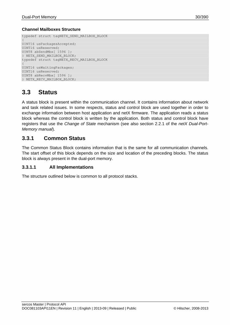
Channel Mailboxes Structure
typedef struct tagNETX_SEND_MAILBOX_BLOCK { UINT16 usPackagesAccepted; UINT16 usReserved; UINT8 abSendMbx[ 1596 ]; } NETX_SEND_MAILBOX_BLOCK; typedef struct tagNETX_RECV_MAILBOX_BLOCK { UINT16 usWaitingPackages; UINT16 usReserved; UINT8 abRecvMbx[ 1596 ]; } NETX_RECV_MAILBOX_BLOCK;
3.3 Status
A status block is present within the communication channel. It contains information about network and task related issues. In some respects, status and control block are used together in order to exchange information between host application and netX firmware. The application reads a status block whereas the control block is written by the application. Both status and control block have registers that use the Change of State mechanism (see also section 2.2.1 of the netX Dual-Port-Memory manual).
3.3.1 Common Status
The Common Status Block contains information that is the same for all communication channels. The start offset of this block depends on the size and location of the preceding blocks. The status block is always present in the dual-port memory.
3.3.1.1 All Implementations
The structure outlined below is common to all protocol stacks.
Dual-Port Memory 31/390
sercos Master | Protocol API DOC081103API11EN | Revision 11 | English | 2013-09 | Released | Public © Hilscher, 2008-2013
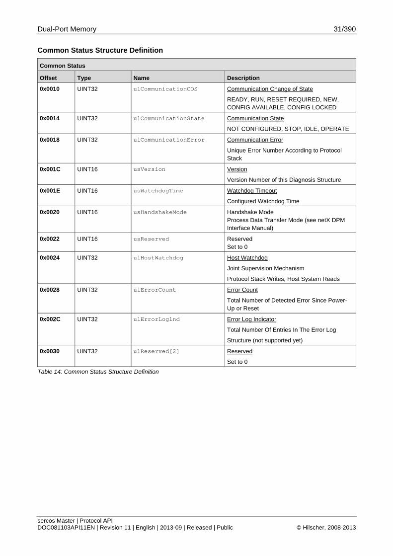
Common Status Structure Definition
Common Status
Offset Type Name Description
0x0010 UINT32 ulCommunicationCOS Communication Change of State
READY, RUN, RESET REQUIRED, NEW, CONFIG AVAILABLE, CONFIG LOCKED
0x0014 UINT32 ulCommunicationState Communication State
NOT CONFIGURED, STOP, IDLE, OPERATE
0x0018 UINT32 ulCommunicationError Communication Error
Unique Error Number According to Protocol Stack
0x001C UINT16 usVersion Version
Version Number of this Diagnosis Structure
0x001E UINT16 usWatchdogTime Watchdog Timeout
Configured Watchdog Time
0x0020 UINT16 usHandshakeMode Handshake Mode Process Data Transfer Mode (see netX DPM Interface Manual)
0x0022 UINT16 usReserved Reserved Set to 0
0x0024 UINT32 ulHostWatchdog Host Watchdog
Joint Supervision Mechanism
Protocol Stack Writes, Host System Reads
0x0028 UINT32 ulErrorCount Error Count
Total Number of Detected Error Since Power-Up or Reset
0x002C UINT32 ulErrorLoglnd Error Log Indicator
Total Number Of Entries In The Error Log
Structure (not supported yet)
0x0030 UINT32 ulReserved[2] Reserved
Set to 0
Table 14: Common Status Structure Definition
Dual-Port Memory 32/390
sercos Master | Protocol API DOC081103API11EN | Revision 11 | English | 2013-09 | Released | Public © Hilscher, 2008-2013
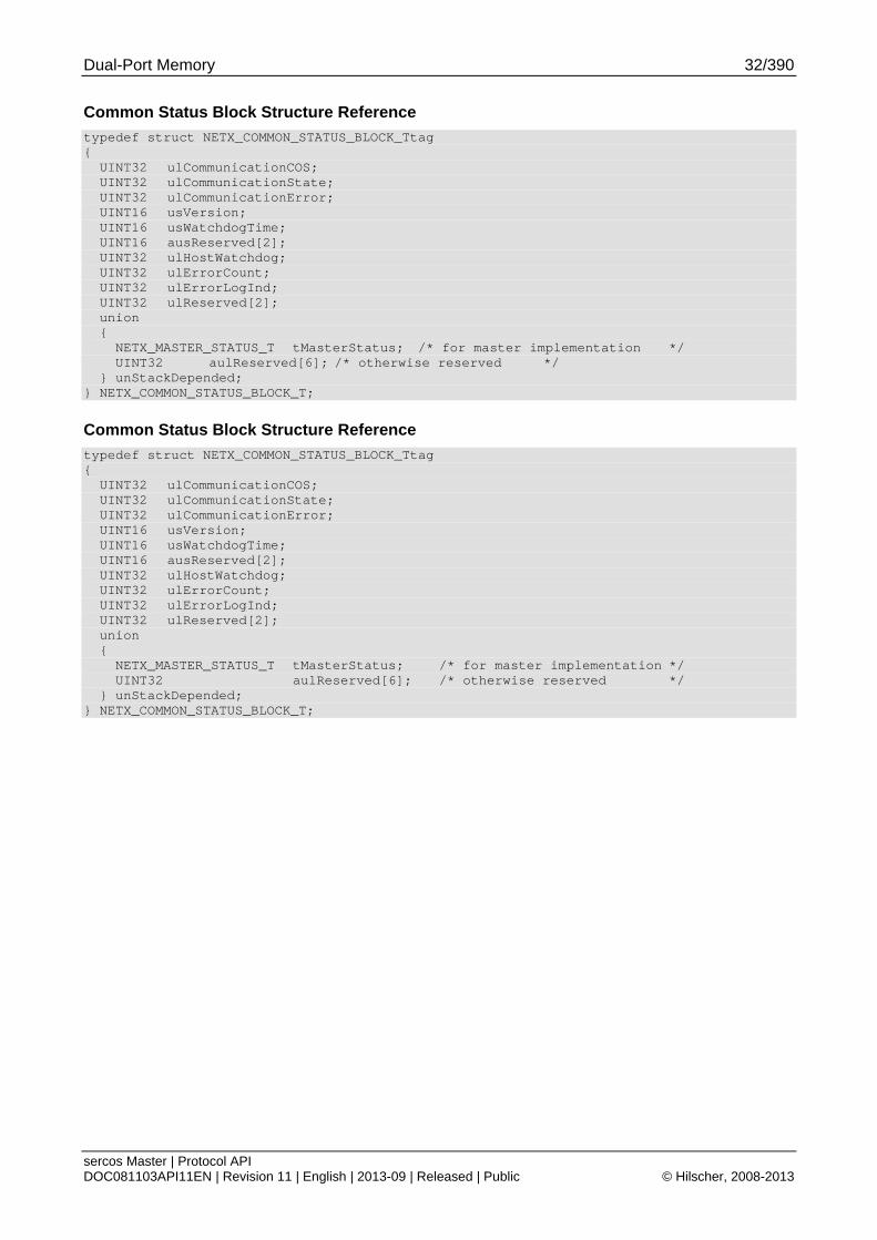
Common Status Block Structure Reference
typedef struct NETX_COMMON_STATUS_BLOCK_Ttag { UINT32 ulCommunicationCOS; UINT32 ulCommunicationState; UINT32 ulCommunicationError; UINT16 usVersion; UINT16 usWatchdogTime; UINT16 ausReserved[2]; UINT32 ulHostWatchdog; UINT32 ulErrorCount; UINT32 ulErrorLogInd; UINT32 ulReserved[2]; union { NETX_MASTER_STATUS_T tMasterStatus; /* for master implementation */ UINT32 aulReserved[6]; /* otherwise reserved */ } unStackDepended; } NETX_COMMON_STATUS_BLOCK_T;
Dual-Port Memory 33/390
sercos Master | Protocol API DOC081103API11EN | Revision 11 | English | 2013-09 | Released | Public © Hilscher, 2008-2013
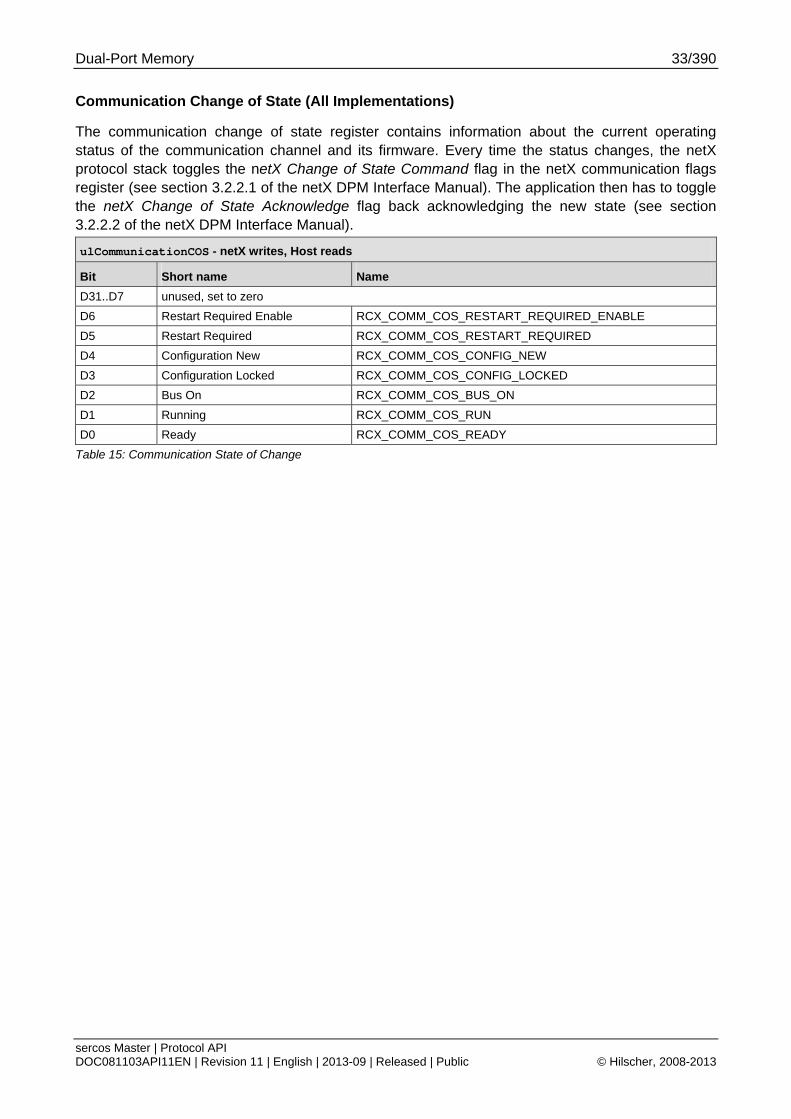
Communication Change of State (All Implementations)
The communication change of state register contains information about the current operating status of the communication channel and its firmware. Every time the status changes, the netX protocol stack toggles the netX Change of State Command flag in the netX communication flags register (see section 3.2.2.1 of the netX DPM Interface Manual). The application then has to toggle the netX Change of State Acknowledge flag back acknowledging the new state (see section 3.2.2.2 of the netX DPM Interface Manual).
ulCommunicationCOS - netX writes, Host reads
Bit Short name Name
D31..D7 unused, set to zero D6 Restart Required Enable RCX_COMM_COS_RESTART_REQUIRED_ENABLE
D5 Restart Required RCX_COMM_COS_RESTART_REQUIRED
D4 Configuration New RCX_COMM_COS_CONFIG_NEW
D3 Configuration Locked RCX_COMM_COS_CONFIG_LOCKED D2 Bus On RCX_COMM_COS_BUS_ON
D1 Running RCX_COMM_COS_RUN
D0 Ready RCX_COMM_COS_READY
Table 15: Communication State of Change
Dual-Port Memory 34/390
sercos Master | Protocol API DOC081103API11EN | Revision 11 | English | 2013-09 | Released | Public © Hilscher, 2008-2013
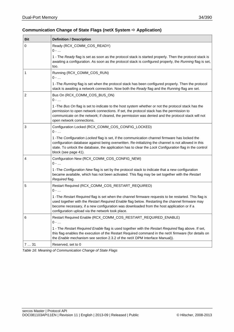
Communication Change of State Flags (netX System Application)
Bit Definition / Description
0 Ready (RCX_COMM_COS_READY) 0 - …
1 - The Ready flag is set as soon as the protocol stack is started properly. Then the protocol stack is awaiting a configuration. As soon as the protocol stack is configured properly, the Running flag is set, too.
1 Running (RCX_COMM_COS_RUN) 0 - …
1 -The Running flag is set when the protocol stack has been configured properly. Then the protocol stack is awaiting a network connection. Now both the Ready flag and the Running flag are set.
2 Bus On (RCX_COMM_COS_BUS_ON) 0 - …
1 -The Bus On flag is set to indicate to the host system whether or not the protocol stack has the permission to open network connections. If set, the protocol stack has the permission to communicate on the network; if cleared, the permission was denied and the protocol stack will not open network connections.
3 Configuration Locked (RCX_COMM_COS_CONFIG_LOCKED) 0 - …
1 -The Configuration Locked flag is set, if the communication channel firmware has locked the configuration database against being overwritten. Re-initializing the channel is not allowed in this state. To unlock the database, the application has to clear the Lock Configuration flag in the control block (see page 41).
4 Configuration New (RCX_COMM_COS_CONFIG_NEW) 0 - …
1 -The Configuration New flag is set by the protocol stack to indicate that a new configuration became available, which has not been activated. This flag may be set together with the Restart Required flag.
5 Restart Required (RCX_COMM_COS_RESTART_REQUIRED) 0 - …
1 -The Restart Required flag is set when the channel firmware requests to be restarted. This flag is used together with the Restart Required Enable flag below. Restarting the channel firmware may become necessary, if a new configuration was downloaded from the host application or if a configuration upload via the network took place.
6 Restart Required Enable (RCX_COMM_COS_RESTART_REQUIRED_ENABLE) 0 - …
1 - The Restart Required Enable flag is used together with the Restart Required flag above. If set, this flag enables the execution of the Restart Required command in the netX firmware (for details on the Enable mechanism see section 2.3.2 of the netX DPM Interface Manual)).
7 … 31 Reserved, set to 0
Table 16: Meaning of Communication Change of State Flags
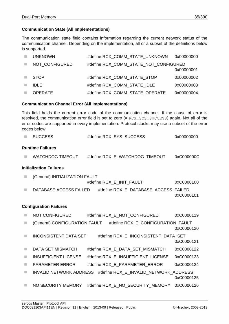
Dual-Port Memory 35/390
sercos Master | Protocol API DOC081103API11EN | Revision 11 | English | 2013-09 | Released | Public © Hilscher, 2008-2013
Communication State (All Implementations)
The communication state field contains information regarding the current network status of the communication channel. Depending on the implementation, all or a subset of the definitions below is supported.
UNKNOWN #define RCX_COMM_STATE_UNKNOWN 0x00000000
NOT_CONFIGURED #define RCX_COMM_STATE_NOT_CONFIGURED 0x00000001
STOP #define RCX_COMM_STATE_STOP 0x00000002
IDLE #define RCX_COMM_STATE_IDLE 0x00000003
OPERATE #define RCX_COMM_STATE_OPERATE 0x00000004
Communication Channel Error (All Implementations)
This field holds the current error code of the communication channel. If the cause of error is resolved, the communication error field is set to zero (= RCX_SYS_SUCCESS) again. Not all of the error codes are supported in every implementation. Protocol stacks may use a subset of the error codes below.
SUCCESS #define RCX_SYS_SUCCESS 0x00000000
Runtime Failures
WATCHDOG TIMEOUT #define RCX_E_WATCHDOG_TIMEOUT 0xC000000C
Initialization Failures
(General) INITIALIZATION FAULT #define RCX_E_INIT_FAULT 0xC0000100
DATABASE ACCESS FAILED #define RCX_E_DATABASE_ACCESS_FAILED 0xC0000101
Configuration Failures
NOT CONFIGURED #define RCX_E_NOT_CONFIGURED 0xC0000119
(General) CONFIGURATION FAULT #define RCX_E_CONFIGURATION_FAULT 0xC0000120
INCONSISTENT DATA SET #define RCX_E_INCONSISTENT_DATA_SET 0xC0000121
DATA SET MISMATCH #define RCX_E_DATA_SET_MISMATCH 0xC0000122
INSUFFICIENT LICENSE #define RCX_E_INSUFFICIENT_LICENSE 0xC0000123
PARAMETER ERROR #define RCX_E_PARAMETER_ERROR 0xC0000124
INVALID NETWORK ADDRESS #define RCX_E_INVALID_NETWORK_ADDRESS 0xC0000125
NO SECURITY MEMORY #define RCX_E_NO_SECURITY_MEMORY 0xC0000126
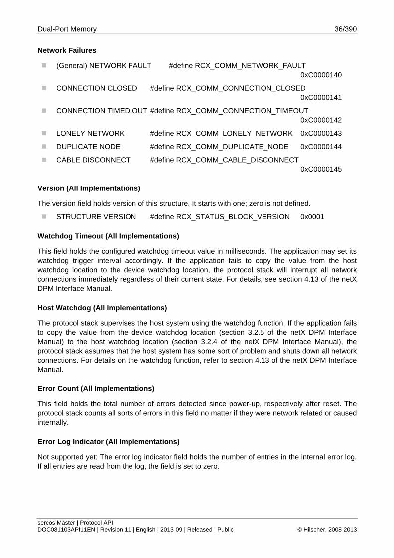
Dual-Port Memory 36/390
sercos Master | Protocol API DOC081103API11EN | Revision 11 | English | 2013-09 | Released | Public © Hilscher, 2008-2013
Network Failures
(General) NETWORK FAULT #define RCX_COMM_NETWORK_FAULT 0xC0000140
CONNECTION CLOSED #define RCX_COMM_CONNECTION_CLOSED 0xC0000141
CONNECTION TIMED OUT #define RCX_COMM_CONNECTION_TIMEOUT 0xC0000142
LONELY NETWORK #define RCX_COMM_LONELY_NETWORK 0xC0000143
DUPLICATE NODE #define RCX_COMM_DUPLICATE_NODE 0xC0000144
CABLE DISCONNECT #define RCX_COMM_CABLE_DISCONNECT 0xC0000145
Version (All Implementations)
The version field holds version of this structure. It starts with one; zero is not defined.
STRUCTURE VERSION #define RCX_STATUS_BLOCK_VERSION 0x0001
Watchdog Timeout (All Implementations)
This field holds the configured watchdog timeout value in milliseconds. The application may set its watchdog trigger interval accordingly. If the application fails to copy the value from the host watchdog location to the device watchdog location, the protocol stack will interrupt all network connections immediately regardless of their current state. For details, see section 4.13 of the netX DPM Interface Manual.
Host Watchdog (All Implementations)
The protocol stack supervises the host system using the watchdog function. If the application fails to copy the value from the device watchdog location (section 3.2.5 of the netX DPM Interface Manual) to the host watchdog location (section 3.2.4 of the netX DPM Interface Manual), the protocol stack assumes that the host system has some sort of problem and shuts down all network connections. For details on the watchdog function, refer to section 4.13 of the netX DPM Interface Manual.
Error Count (All Implementations)
This field holds the total number of errors detected since power-up, respectively after reset. The protocol stack counts all sorts of errors in this field no matter if they were network related or caused internally.
Error Log Indicator (All Implementations)
Not supported yet: The error log indicator field holds the number of entries in the internal error log. If all entries are read from the log, the field is set to zero.
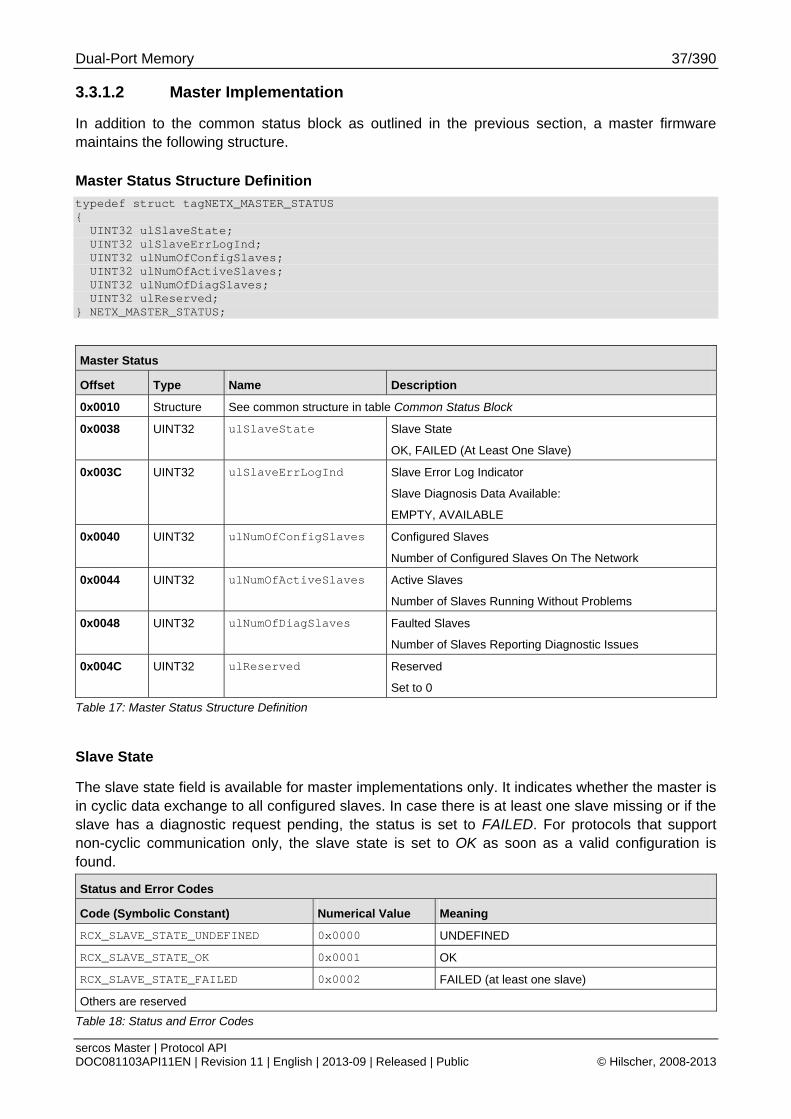
Dual-Port Memory 37/390
sercos Master | Protocol API DOC081103API11EN | Revision 11 | English | 2013-09 | Released | Public © Hilscher, 2008-2013
3.3.1.2 Master Implementation
In addition to the common status block as outlined in the previous section, a master firmware maintains the following structure.
Master Status Structure Definition
typedef struct tagNETX_MASTER_STATUS { UINT32 ulSlaveState; UINT32 ulSlaveErrLogInd; UINT32 ulNumOfConfigSlaves; UINT32 ulNumOfActiveSlaves; UINT32 ulNumOfDiagSlaves; UINT32 ulReserved; } NETX_MASTER_STATUS;
Master Status
Offset Type Name Description
0x0010 Structure See common structure in table Common Status Block
0x0038 UINT32 ulSlaveState Slave State
OK, FAILED (At Least One Slave)
0x003C UINT32 ulSlaveErrLogInd
Slave Error Log Indicator
Slave Diagnosis Data Available:
EMPTY, AVAILABLE
0x0040 UINT32 ulNumOfConfigSlaves Configured Slaves
Number of Configured Slaves On The Network
0x0044 UINT32 ulNumOfActiveSlaves Active Slaves
Number of Slaves Running Without Problems
0x0048 UINT32 ulNumOfDiagSlaves Faulted Slaves
Number of Slaves Reporting Diagnostic Issues
0x004C UINT32 ulReserved Reserved
Set to 0
Table 17: Master Status Structure Definition
Slave State
The slave state field is available for master implementations only. It indicates whether the master is in cyclic data exchange to all configured slaves. In case there is at least one slave missing or if the slave has a diagnostic request pending, the status is set to FAILED. For protocols that support non-cyclic communication only, the slave state is set to OK as soon as a valid configuration is found.
Status and Error Codes
Code (Symbolic Constant) Numerical Value Meaning
RCX_SLAVE_STATE_UNDEFINED 0x0000 UNDEFINED
RCX_SLAVE_STATE_OK 0x0001 OK
RCX_SLAVE_STATE_FAILED 0x0002 FAILED (at least one slave)
Others are reserved
Table 18: Status and Error Codes
Dual-Port Memory 38/390
sercos Master | Protocol API DOC081103API11EN | Revision 11 | English | 2013-09 | Released | Public © Hilscher, 2008-2013
Slave Error Log Indicator
The error log indicator field holds the number of entries in the internal error log. If all entries are read from the log, the field is set to zero.
Note: This function is not yet supported.
Number of Configured Slaves
The firmware maintains a list of slaves to which the master has to open a connection. This list is derived from the configuration database created by SYCON.net (see 6.1). This field holds the number of configured slaves.
Number of Active Slaves
The firmware maintains a list of slaves to which the master has successfully opened a connection.
Ideally, the number of active slaves is equal to the number of configured slaves. For certain fieldbus systems it could be possible that the slave is shown as activated, but still has a problem in terms of a diagnostic issue. This field holds the number of active slaves.
Number of Faulted Slaves
If a slave encounters a problem, it can provide an indication of the new situation to the master in certain fieldbus systems. As long as those indications are pending and not serviced, the field holds a value unequal zero. If no more diagnostic information is pending, the field is set to zero.
3.3.1.3 Slave Implementation
The slave firmware uses only the common structure as outlined in section 3.2.5.1 of the Hilscher netX Dual-Port-Memory Manual.
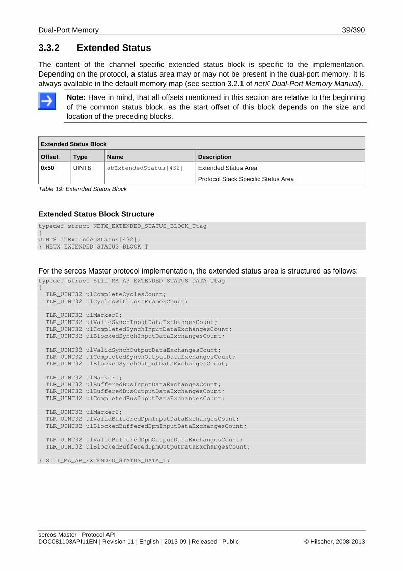
Dual-Port Memory 39/390
sercos Master | Protocol API DOC081103API11EN | Revision 11 | English | 2013-09 | Released | Public © Hilscher, 2008-2013
3.3.2 Extended Status
The content of the channel specific extended status block is specific to the implementation. Depending on the protocol, a status area may or may not be present in the dual-port memory. It is always available in the default memory map (see section 3.2.1 of netX Dual-Port Memory Manual).
Note: Have in mind, that all offsets mentioned in this section are relative to the beginning of the common status block, as the start offset of this block depends on the size and location of the preceding blocks.
Extended Status Block
Offset Type Name Description
0x50 UINT8 abExtendedStatus[432] Extended Status Area
Protocol Stack Specific Status Area
Table 19: Extended Status Block
Extended Status Block Structure
typedef struct NETX_EXTENDED_STATUS_BLOCK_Ttag { UINT8 abExtendedStatus[432]; } NETX_EXTENDED_STATUS_BLOCK_T
For the sercos Master protocol implementation, the extended status area is structured as follows: typedef struct SIII_MA_AP_EXTENDED_STATUS_DATA_Ttag { TLR_UINT32 ulCompleteCyclesCount; TLR_UINT32 ulCyclesWithLostFramesCount; TLR_UINT32 ulMarker0; TLR_UINT32 ulValidSynchInputDataExchangesCount; TLR_UINT32 ulCompletedSynchInputDataExchangesCount; TLR_UINT32 ulBlockedSynchInputDataExchangesCount; TLR_UINT32 ulValidSynchOutputDataExchangesCount; TLR_UINT32 ulCompletedSynchOutputDataExchangesCount; TLR_UINT32 ulBlockedSynchOutputDataExchangesCount; TLR_UINT32 ulMarker1; TLR_UINT32 ulBufferedBusInputDataExchangesCount; TLR_UINT32 ulBufferedBusOutputDataExchangesCount; TLR_UINT32 ulCompletedBusInputDataExchangesCount; TLR_UINT32 ulMarker2; TLR_UINT32 ulValidBufferedDpmInputDataExchangesCount; TLR_UINT32 ulBlockedBufferedDpmInputDataExchangesCount; TLR_UINT32 ulValidBufferedDpmOutputDataExchangesCount; TLR_UINT32 ulBlockedBufferedDpmOutputDataExchangesCount; } SIII_MA_AP_EXTENDED_STATUS_DATA_T;
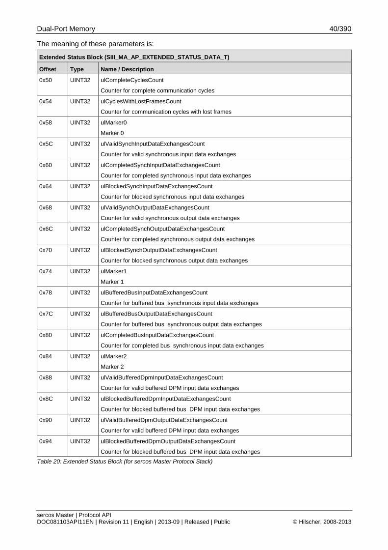
Dual-Port Memory 40/390
sercos Master | Protocol API DOC081103API11EN | Revision 11 | English | 2013-09 | Released | Public © Hilscher, 2008-2013
The meaning of these parameters is:
Extended Status Block (SIII_MA_AP_EXTENDED_STATUS_DATA_T)
Offset Type Name / Description
0x50 UINT32 ulCompleteCyclesCount
Counter for complete communication cycles
0x54 UINT32 ulCyclesWithLostFramesCount
Counter for communication cycles with lost frames
0x58 UINT32 ulMarker0
Marker 0
0x5C UINT32 ulValidSynchInputDataExchangesCount
Counter for valid synchronous input data exchanges
0x60 UINT32 ulCompletedSynchInputDataExchangesCount
Counter for completed synchronous input data exchanges
0x64 UINT32 ulBlockedSynchInputDataExchangesCount
Counter for blocked synchronous input data exchanges
0x68 UINT32 ulValidSynchOutputDataExchangesCount
Counter for valid synchronous output data exchanges
0x6C UINT32 ulCompletedSynchOutputDataExchangesCount
Counter for completed synchronous output data exchanges
0x70 UINT32 ulBlockedSynchOutputDataExchangesCount
Counter for blocked synchronous output data exchanges
0x74 UINT32 ulMarker1
Marker 1
0x78 UINT32 ulBufferedBusInputDataExchangesCount
Counter for buffered bus synchronous input data exchanges
0x7C UINT32 ulBufferedBusOutputDataExchangesCount
Counter for buffered bus synchronous output data exchanges
0x80 UINT32 ulCompletedBusInputDataExchangesCount
Counter for completed bus synchronous input data exchanges
0x84 UINT32 ulMarker2
Marker 2
0x88 UINT32 ulValidBufferedDpmInputDataExchangesCount
Counter for valid buffered DPM input data exchanges
0x8C UINT32 ulBlockedBufferedDpmInputDataExchangesCount
Counter for blocked buffered bus DPM input data exchanges
0x90 UINT32 ulValidBufferedDpmOutputDataExchangesCount
Counter for valid buffered DPM input data exchanges
0x94 UINT32 ulBlockedBufferedDpmOutputDataExchangesCount
Counter for blocked buffered bus DPM input data exchanges
Table 20: Extended Status Block (for sercos Master Protocol Stack)
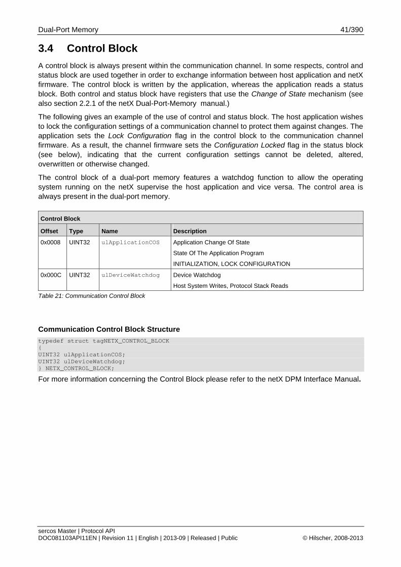
Dual-Port Memory 41/390
sercos Master | Protocol API DOC081103API11EN | Revision 11 | English | 2013-09 | Released | Public © Hilscher, 2008-2013
3.4 Control Block
A control block is always present within the communication channel. In some respects, control and status block are used together in order to exchange information between host application and netX firmware. The control block is written by the application, whereas the application reads a status block. Both control and status block have registers that use the Change of State mechanism (see also section 2.2.1 of the netX Dual-Port-Memory manual.)
The following gives an example of the use of control and status block. The host application wishes to lock the configuration settings of a communication channel to protect them against changes. The application sets the Lock Configuration flag in the control block to the communication channel firmware. As a result, the channel firmware sets the Configuration Locked flag in the status block (see below), indicating that the current configuration settings cannot be deleted, altered, overwritten or otherwise changed.
The control block of a dual-port memory features a watchdog function to allow the operating system running on the netX supervise the host application and vice versa. The control area is always present in the dual-port memory.
Control Block
Offset Type Name Description
0x0008 UINT32 ulApplicationCOS
Application Change Of State
State Of The Application Program
INITIALIZATION, LOCK CONFIGURATION
0x000C UINT32 ulDeviceWatchdog Device Watchdog
Host System Writes, Protocol Stack Reads
Table 21: Communication Control Block
Communication Control Block Structure
typedef struct tagNETX_CONTROL_BLOCK { UINT32 ulApplicationCOS; UINT32 ulDeviceWatchdog; } NETX_CONTROL_BLOCK;
For more information concerning the Control Block please refer to the netX DPM Interface Manual.
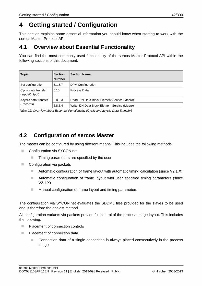
Getting started / Configuration 42/390
sercos Master | Protocol API DOC081103API11EN | Revision 11 | English | 2013-09 | Released | Public © Hilscher, 2008-2013
4 Getting started / Configuration This section explains some essential information you should know when starting to work with the sercos Master Protocol API.
4.1 Overview about Essential Functionality
You can find the most commonly used functionality of the sercos Master Protocol API within the following sections of this document:
Topic Section
Number
Section Name
Set configuration 6.1.6.7 DPM Configuration
Cyclic data transfer (Input/Output)
5.10 Process Data
6.8.5.3 Read IDN Data Block Element Service (Macro) Acyclic data transfer (Records) 6.8.5.4 Write IDN Data Block Element Service (Macro)
Table 22: Overview about Essential Functionality (Cyclic and acyclic Data Transfer)
4.2 Configuration of sercos Master
The master can be configured by using different means. This includes the following methods:
Configuration via SYCON.net
Timing parameters are specified by the user
Configuration via packets
Automatic configuration of frame layout with automatic timing calculation (since V2.1.X)
Automatic configuration of frame layout with user specified timing parameters (since V2.1.X)
Manual configuration of frame layout and timing parameters
The configuration via SYCON.net evaluates the SDDML files provided for the slaves to be used and is therefore the easiest method.
All configuration variants via packets provide full control of the process image layout. This includes the following:
Placement of connection controls
Placement of connection data
Connection data of a single connection is always placed consecutively in the process image
Getting started / Configuration 43/390
sercos Master | Protocol API DOC081103API11EN | Revision 11 | English | 2013-09 | Released | Public © Hilscher, 2008-2013
4.2.1 Using the configuration tool SYCON.net
The easiest way to configure the sercos Master is using Hilscher’s configuration tool SYCON.net.
First, you need to create a project in SYCON.net. This is described in detail in the SYCON.net documentation.
Configure the bus and master parameters as described in the SYCON.net documentation.
After you completed your project, you can right-click on the icon of the sercos Master and select "Connect".
You will see that the name of the sercos Master will get a green background. Now right-click on the icon again and select "Download".
This will download the configuration files into the firmware. It is stored in a RAM Disk in a channel dependent directory ("PORT_0" for channel 0, "PORT_1” for channel 1, etc.).
After the download is finished, the driver requests the sercos Master firmware to perform a Channel-Init. All current connections will be shut down by the firmware and a restart will be performed.
During this restart, the configuration that has been downloaded previously will be evaluated and used.
Getting started / Configuration 44/390
sercos Master | Protocol API DOC081103API11EN | Revision 11 | English | 2013-09 | Released | Public © Hilscher, 2008-2013
4.2.2 Using configuration via packets
The following sections will outline the different variants for configuring the master via packets. All variants provide full control of the process image layout. In addition, some variants provide additional control of frame layout and timing parameters. If the slaves require writes to particular IDNs, these must be explicitly specified via 6.1.6.5 Add InitCmd Service
Note: The master must be in communication phase NRT to accept configuration via packets.
The following packet configuration variants are possible:
Automatic configuration of frame layout with automatic timing calculation (since V2.1.X)
Automatic configuration of frame layout with user specified timing parameters (since V2.1.X)
Manual configuration of frame layout and timing parameters
4.2.2.1 Automatic configuration of frame layout with automatic timing calculation
This configuration method is selected within the field ulStackConfigurationFlags of 6.1.6.1 Begin a new Configuration Transfer Service by setting the bits 2 and 5. For details, see chapter 6.1.7 Automatic Configuration of Frame Layout with automatic Timing Calculation
The automatic timing calculation has four different selectable timing options (depending on bits 4 and bits 3 of ulStackConfigurationFlags):
No NRT during CP3/CP4
MDT/AT/NRT
MDT/NRT/AT; minimum sized NRT channel and AT placed close to its end
MDT/NRT/AT; maximum sized NRT channel and AT placed close to end of cycle
The maximum possible MTU is determined internally by master.
The timing variants are described in chapter 6.1.7.3 Configurable Timing Variants in more detail.
The following parameters of 6.1.6.1 Begin a new Configuration Transfer Service are evaluated:
Communication cycle time
Communication timeout (Allowed MST losses)
Output Process Data image size
Input Process Data image size
Minimum CP0 Wait Cycles
For detailed description of the parameters, see 4.2.3 Detailed Description of Master Parameters.
For detailed explanation of how to use the configuration method, see 6.1.7 Automatic Configuration of Frame Layout with automatic Timing Calculation.
Getting started / Configuration 45/390
sercos Master | Protocol API DOC081103API11EN | Revision 11 | English | 2013-09 | Released | Public © Hilscher, 2008-2013
4.2.2.2 Automatic configuration of frame layout with user specified timing parameters
This configuration method is selected within the field ulStackConfigurationFlags of 6.1.6.1 Begin a new Configuration Transfer Service by setting the bit 2 and keeping bit 5 cleared. For details, see chapter 0
Automatic Configuration of Frame Layout with user specified Timing Parameters.
All timing parameters have to be determined by the user. The frame layout is calculated by the master internally.
Note: The timing parameters must be suitable for the frame layout calculated by the master i.e. the frames must fit into the specified timing.
The following parameters of 6.1.6.1 “Begin a new Configuration Transfer Service” are evaluated:
Communication cycle time
Communication timeout (Allowed MST losses)
Command value valid time (t3)
AT Transmission Starting Time (t1)
NRT transmission start time (t6)
NRT transmission end time (t7)
Synchronization time
NRT channel MTU
Output Process Data image size
Input Process Data image size
Minimum CP0 Wait Cycles
For detailed description of the parameters, see 4.2.3 “Detailed Description of Master Parameters”.
For detailed explanation of how to use the configuration method, see 6.1.8 “Automatic Configuration of Frame Layout with user specified Timing Parameters”
Automatic Configuration of Frame Layout with user specified Timing Parameters .
Getting started / Configuration 46/390
sercos Master | Protocol API DOC081103API11EN | Revision 11 | English | 2013-09 | Released | Public © Hilscher, 2008-2013
4.2.2.3 Manual configuration of frame layout and timing parameters
This configuration method is selected within the field ulStackConfigurationFlags of 6.1.6.1 Begin a new Configuration Transfer Service by keeping the bits 2 and 5 cleared. For details, see chapter 6.1.11 Manual Configuration of Frame Layout and Timing Parameters.
All timing parameters have to be determined by the user. The frame layout is specified via configuration packets.
The timing parameters must be suitable for the frame layout specified by the packets i.e. the frames must fit into the specified timing.
The following parameters of 6.1.6.1 Begin a new Configuration Transfer Service are evaluated:
Communication cycle time
Communication timeout (Allowed MST losses)
Command value valid time (t3)
AT Transmission Starting Time (t1)
NRT transmission start time (t6)
NRT transmission end time (t7)
Synchronization time
NRT channel MTU
Output Process Data image size
Input Process Data image size
Minimum CP0 Wait Cycles
For detailed description of the parameters, see 4.2.3 Detailed Description of Master Parameters.
For detailed explanation of how to use the configuration method, see 6.1.11 Manual Configuration of Frame Layout and Timing Parameters.
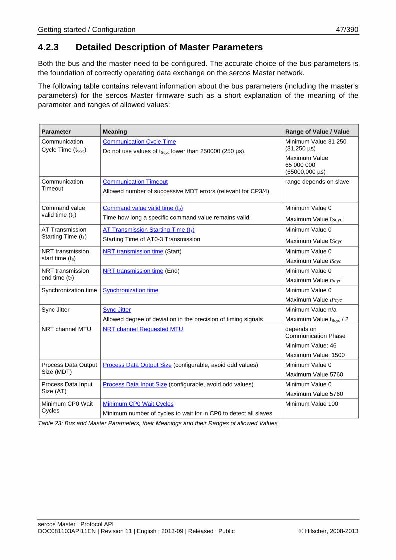
Getting started / Configuration 47/390
sercos Master | Protocol API DOC081103API11EN | Revision 11 | English | 2013-09 | Released | Public © Hilscher, 2008-2013
4.2.3 Detailed Description of Master Parameters
Both the bus and the master need to be configured. The accurate choice of the bus parameters is the foundation of correctly operating data exchange on the sercos Master network.
The following table contains relevant information about the bus parameters (including the master’s parameters) for the sercos Master firmware such as a short explanation of the meaning of the parameter and ranges of allowed values:
Parameter Meaning Range of Value / Value
Communication Cycle Time (tScyc)
Communication Cycle Time
Do not use values of tScyc lower than 250000 (250 µs).
Minimum Value 31 250 (31,250 µs)
Maximum Value 65 000 000 (65000,000 µs)
Communication Timeout
Communication Timeout
Allowed number of successive MDT errors (relevant for CP3/4)
range depends on slave
Command value valid time (t3)
Command value valid time (t3)
Time how long a specific command value remains valid.
Minimum Value 0
Maximum Value tScyc
AT Transmission Starting Time (t1)
AT Transmission Starting Time (t1)
Starting Time of AT0-3 Transmission
Minimum Value 0
Maximum Value tScyc
NRT transmission start time (t6)
NRT transmission time (Start) Minimum Value 0
Maximum Value tScyc
NRT transmission end time (t7)
NRT transmission time (End) Minimum Value 0
Maximum Value tScyc
Synchronization time Synchronization time Minimum Value 0
Maximum Value tPcyc
Sync Jitter Sync Jitter
Allowed degree of deviation in the precision of timing signals
Minimum Value n/a
Maximum Value tScyc / 2 NRT channel MTU NRT channel Requested MTU depends on
Communication Phase
Minimum Value: 46
Maximum Value: 1500
Process Data Output Size (MDT)
Process Data Output Size (configurable, avoid odd values) Minimum Value 0
Maximum Value 5760
Process Data Input Size (AT)
Process Data Input Size (configurable, avoid odd values) Minimum Value 0
Maximum Value 5760
Minimum CP0 Wait Cycles
Minimum CP0 Wait Cycles
Minimum number of cycles to wait for in CP0 to detect all slaves
Minimum Value 100
Table 23: Bus and Master Parameters, their Meanings and their Ranges of allowed Values
Getting started / Configuration 48/390
sercos Master | Protocol API DOC081103API11EN | Revision 11 | English | 2013-09 | Released | Public © Hilscher, 2008-2013
4.2.3.1 Communication Cycle Time (tScyc)
The communication cycle time specifies the actual bus cycle used in CP3 and CP4. The value is written to the IDN S-0-1002 on all slaves by the master.
The specification of communication cycle time (tScyc) defines 31,25 µs, 62,5 µs, 125 µs, 250 µs, 500 µs, 750 µs, 1 ms, 1,25 ms ... up to 65 ms in steps of 250 µs.
Note: Due to processing required within the master, the minimum value of tScyc is 250 µs.
4.2.3.2 Communication Timeout
This parameter specifies the allowed MST losses a slave has to accept in CP3/CP4. Any higher amount of successive MDT losses is considered an error by slaves and result into a fallback. The value is written into the IDN S-0-1003 on all slaves by the master.
This value should be higher than any allowed data losses specified on the connections to ensure that the master can still communicate with the slaves.
4.2.3.3 Command Value Valid Time
This parameter describes the command value valid time. In the sercos specification this value is often denominated as t3. This item corresponds to IDN S-0-1008.
4.2.3.4 AT Transmission Starting Time (t1)
The AT Transmission starting time specifies when the AT0 telegram is sent on the bus after the MST. The value is written into the IDN S-0-1006 by the master on all slaves supporting SCP_Sync.
4.2.3.5 NRT Transmission Time (t6, t7)
The NRT Transmission Time parameters specify the start and the end time of the NRT window. They are written into the IDN S-0-1017 on all slaves by the master.
The minimum NRT window has to be 6.72 µs. If t6 is 0, the NRT channel is completely switched off.
If the difference between t7 and t6 is less than 125 µs, then the NRT channel MTU must be adjusted very precisely, see section 4.2.3.7 “Sync Jitter”below.
4.2.3.6 Feedback acquisition time (Synchronization time) (t4)
The feedback acquisition time specifies when the feedbacks should be taken by the slaves supporting SCP_Sync. The reference time point for t4 is tSref which is determined by synchronization measurement. tSref is reached by all slaves at the same time. Slaves supporting SCP_Sync will optionally produce the CON-CLK at the specified time point. The parameter is written to IDN S-0-1007 on all slaves supporting SCP_Sync.
Getting started / Configuration 49/390
sercos Master | Protocol API DOC081103API11EN | Revision 11 | English | 2013-09 | Released | Public © Hilscher, 2008-2013
4.2.3.7 Sync Jitter
The master calculates the maximum synchronization jitter. This information is used by the slave for the calculation of its MST window. The parameter is stored in IDN S-0-1023.
4.2.3.8 NRT channel Requested MTU
The parameter defines the largest frame that can be sent through the NRT frame. The parameter is written to IDN S-0-1027.0.1 on all slaves supporting SCP_NRT.
4.2.3.9 Process Data Output Size (MDT)
This parameter determines the size of the area to be used for Process Data Output. It may not exceed the size of available space in DPM which is 5760 bytes. The parameter should be dividable by 2 without remainder.
4.2.3.10 Process Data Input Size (AT)
This parameter determines the size of the area to be used for Process Data Input. It may not exceed the size of available space in DPM which is 5760 bytes. The parameter should be dividable by 2 without remainder.
4.2.3.11 Minimum CP0 Wait Cycles
The master will check for the specified amount of consecutively received identical CP0 frames to consider the detection stable. If a change occurs, the master will reset its internal counter.
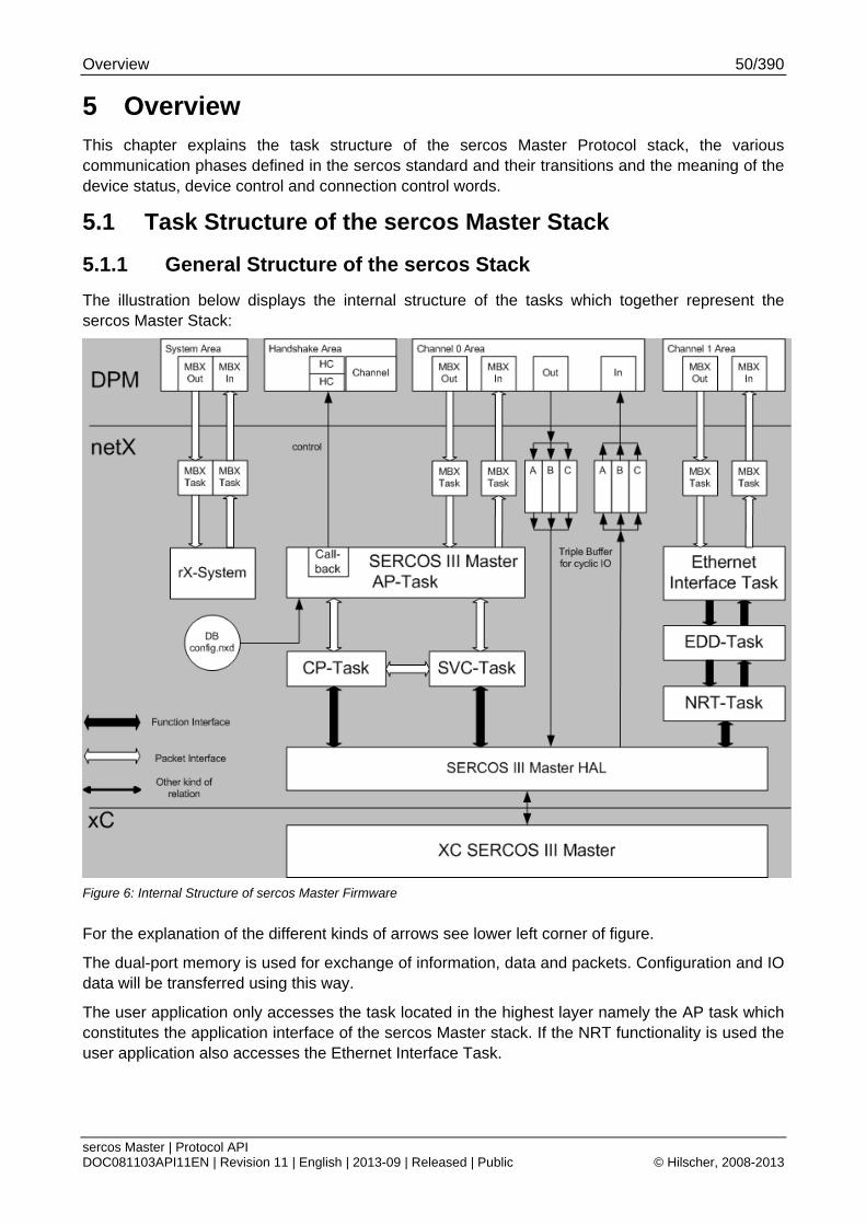
Overview 50/390
sercos Master | Protocol API DOC081103API11EN | Revision 11 | English | 2013-09 | Released | Public © Hilscher, 2008-2013
5 Overview This chapter explains the task structure of the sercos Master Protocol stack, the various communication phases defined in the sercos standard and their transitions and the meaning of the device status, device control and connection control words.
5.1 Task Structure of the sercos Master Stack
5.1.1 General Structure of the sercos Stack
The illustration below displays the internal structure of the tasks which together represent the sercos Master Stack:
Figure 6: Internal Structure of sercos Master Firmware
For the explanation of the different kinds of arrows see lower left corner of figure.
The dual-port memory is used for exchange of information, data and packets. Configuration and IO data will be transferred using this way.
The user application only accesses the task located in the highest layer namely the AP task which constitutes the application interface of the sercos Master stack. If the NRT functionality is used the user application also accesses the Ethernet Interface Task.
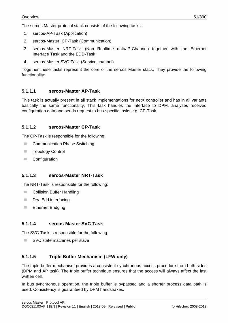
Overview 51/390
sercos Master | Protocol API DOC081103API11EN | Revision 11 | English | 2013-09 | Released | Public © Hilscher, 2008-2013
The sercos Master protocol stack consists of the following tasks:
1. sercos-AP-Task (Application)
2. sercos-Master CP-Task (Communication)
3. sercos-Master NRT-Task (Non Realtime data/IP-Channel) together with the Ethernet Interface Task and the EDD-Task
4. sercos-Master SVC-Task (Service channel)
Together these tasks represent the core of the sercos Master stack. They provide the following functionality:
5.1.1.1 sercos-Master AP-Task
This task is actually present in all stack implementations for netX controller and has in all variants basically the same functionality. This task handles the interface to DPM, analyses received configuration data and sends request to bus-specific tasks e.g. CP-Task.
5.1.1.2 sercos-Master CP-Task
The CP-Task is responsible for the following:
Communication Phase Switching
Topology Control
Configuration
5.1.1.3 sercos-Master NRT-Task
The NRT-Task is responsible for the following:
Collision Buffer Handling
Drv_Edd interfacing
Ethernet Bridging
5.1.1.4 sercos-Master SVC-Task
The SVC-Task is responsible for the following:
SVC state machines per slave
5.1.1.5 Triple Buffer Mechanism (LFW only)
The triple buffer mechanism provides a consistent synchronous access procedure from both sides (DPM and AP task). The triple buffer technique ensures that the access will always affect the last written cell.
In bus synchronous operation, the triple buffer is bypassed and a shorter process data path is used. Consistency is guaranteed by DPM handshakes.
Overview 52/390
sercos Master | Protocol API DOC081103API11EN | Revision 11 | English | 2013-09 | Released | Public © Hilscher, 2008-2013
5.2 State Machine (Communication Phases)
This section explains the general states in which the master can be. It discusses some of the most important aspects of the various communication phases and their transitions. It also explains the structure of the sent data telegrams depending on the communication phase.
5.2.1 State Transitions
The following illustration explains the possible transitions between the states of the sercos master:
Figure 7: Permitted Communication Phase Transitions
When switching between two states, the sercos master is temporarily in an intermediate state CPS (Communication phase switching).
Overview 53/390
sercos Master | Protocol API DOC081103API11EN | Revision 11 | English | 2013-09 | Released | Public © Hilscher, 2008-2013
5.2.2 Non real-time Mode (NRT Mode)
In this mode, only non-sercos frames are communicated between all devices. The master also has to determine the topology status based on a beacon frame to prevent circulating frames. The beacon frame is used to control the collision buffer of the master.
5.2.3 Communication Phase 0 (CP0)
Communication Phase 0 is used by the master to determine the slaves and the topology status. The master will continuously check the received CP0 frames for changes and adjust the topology status accordingly. There is no other communication possible during CP0 (i.e. no service channels).
5.2.3.1 Transition to Communication Phase 1
If the master sees that the AT0 frames in CP0 have the expected content and are stable for at least N cycles, the master will transition to CP1.
N could be configured and has usually the value 100.
There are two necessary conditions under which the sercos network will proceed from CP0 to CP1:
The sercos master has received N (usually 100) AT telegrams with identical contents.
If the sercos master has a configuration loaded, it will only proceed, if the expected and found slave addresses match.
5.2.4 Communication Phase 1 (CP1)
In CP1, the master is initializing the service channels for acyclic communication i.e. ensuring that the service channel state of the slaves is known. In addition, the master checks that all slaves have reached CP1 successfully.
5.2.4.1 Transition to Communication Phase 2
If all slaves have reached the expected service channel state, the master will switch to CP2.

Overview 54/390
sercos Master | Protocol API DOC081103API11EN | Revision 11 | English | 2013-09 | Released | Public © Hilscher, 2008-2013
5.2.5 Communication Phase 2 (CP2)
CP2 is used for transmitting parameters to the slaves which are needed for communication within CP3. These parameters are mostly frame layout and timing configuration.
Acyclic communication via service channels and NRT channel is operational.
5.2.5.1 Transition to Communication Phase 3
When having done all preparations necessary in CP2, the master will activate S-0-0127 procedure command on every slave in order to test the readiness of these slaves and to prepare switching to CP3. If all slaves successfully perform this procedure command, the master will subsequently switch to CP3.
5.2.6 Communication Phase 3 (CP3)
CP3 is used for preparing the slaves for communication. The master will write parameters to all slaves that require additional parameters in CP3.
No actual process data is exchanged in CP3. All connections are typically filled with all zeroes. It is considered to be invalid.
Acyclic communication via service channels and NRT channel is operational.
5.2.6.1 Transition to Communication Phase 4
When having done all preparations necessary in CP3, the master will activate S-0-0128 procedure command on every slave. If all slaves successfully perform this procedure command, the master will subsequently switch to CP4. During processing of this procedure command the slave has to check the validity of the transmitted parameters for CP4 and to activate the synchronization.
5.2.7 Communication Phase 4 (CP4)
During CP4 all services are available. These include:
Acyclic communication via service channels
Process data exchange (process data is valid)
NRT channel if configured
For more information about the details of the sercos communication phases please refer to the sercos specification.
Overview 55/390
sercos Master | Protocol API DOC081103API11EN | Revision 11 | English | 2013-09 | Released | Public © Hilscher, 2008-2013
5.3 SCP Classes
5.3.1 SCP_FixCFG / SCP_VarCFG / SCP_RTB (Real-Time Bits)
The master supports all FixCFG variants defined in sercos specification V1.3.
The master supports all VarCFG variants defined in sercos specification V1.3.
The bits for Flow-Control and Real-time bits are transparently passed through and therefore accessible by the application.
If application controlled C-CON mode is selected, all bits are transparently passed.
In internal controlled C-CON toggle, the master produces the toggle bit and the counter.
5.3.2 SCP_Sync
The master supports all variants defined in sercos specification V1.3.
Variant SCP_Sync_0x03 allows slave-specific override for the S-0-1007 tSync which can be configured by providing a slave-specific CP2 parameter for that IDN within the configuration.
The related Maximum TS-ref counter must be provided by the application through the configuration.
By configuring a non-zero value, the master will activate the extended sys time field.
5.3.3 SCP_SysTime
The master supports to transfer the global SysTime according to sercos specification V1.3.
It can be enabled by the flag MSK_SIII_MA_CP_USE_SERCOS_TIME_EXTENDED_FIELD within the 6.1.11.3 Stack Configuration Flags.
5.3.4 SCP_WD / SCP_WDCon
These classes use a set of IDN parameters to be downloaded by the master. The master accepts their parameters as startup parameters. The current watchdog implementation for consumer data is left to the application.
5.3.5 SCP_Diag
This class consists of a set of IDNs for diagnosis. These IDNs can be accessed through service channel functions.
5.3.6 SCP_HP (Hot Plug)
Hot Plug is supported by the master and whether a slave will be accepted for hot plug depends on the configuration.
5.3.7 SCP_SMP
This class consists of a set of IDNs (some are process data). The configuration of the sercos multiplex protocol can be provided through the configuration. These parameters are transparently downloaded to the slave.
Overview 56/390
sercos Master | Protocol API DOC081103API11EN | Revision 11 | English | 2013-09 | Released | Public © Hilscher, 2008-2013
5.3.8 SCP_MuX / SCP_ExtMuX (multiplex channel)
This class consists of a set of IDNs (some are process data). The configuration of the multiplex channel can be provided through the configuration. These parameters are transparently downloaded to the slave.
5.3.9 SCP_SIG / SCP_RTBListProd / SCP_RTBListCons / SCP_RTBWordProd / SCP_RTBWordCons
These classes are referring to configuration parameters of the real-time bits and their parameters can be transparently passed through the configuration of the master. Access to the real-time bits is provided through the process data image of the master.
5.3.10 SCP_ListSeg
This class allows a segmented access to List IDNs. The transfer can be written in steps with this class. The access to the IDNs related to this class can be accessed through service channel functions.
5.3.11 SCP_NRT / SCP_NRTPC
These classes refer to the ability to communicate via non-sercos communication in the NRT channel. The IDNs can be accessed through service channel functions.
5.3.12 SCP_SIP
This class is currently not used by the master itself but can be used through the NRT channel.
5.3.13 SCP_TFTP
This class is currently not used by the master itself but can be used through the NRT channel.
5.3.14 SCP_Cap
Parameters for this class can be provided in the master configuration and are downloaded transparently on boot up.
5.3.15 SCP_SafetyCon
The master itself does not provide safety features. However, an application can provide configuration parameters for this SCP class and access the process data through the process data image transparently.
5.3.16 SCP_OvSBasic
The configuration parameters for this communication class can be configured within the master configuration and are transparently downloaded. The process data related to this SCP class can be accessed through the process data image.
5.3.17 SCP_Cyc
This class adds the AT transmission starting time parameter (IDN S-0-1006). If the master detects this SCP class, it will download the respective time to the slave.
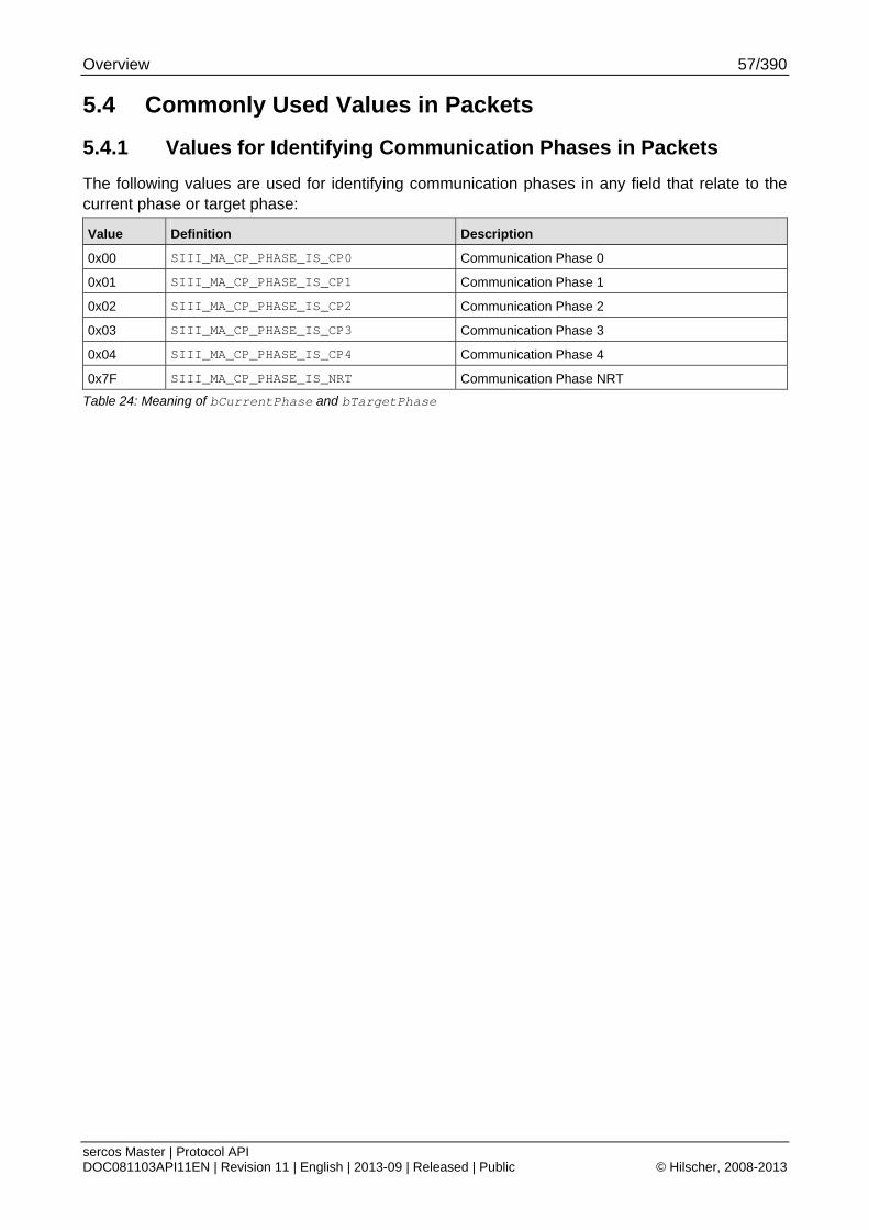
Overview 57/390
sercos Master | Protocol API DOC081103API11EN | Revision 11 | English | 2013-09 | Released | Public © Hilscher, 2008-2013
5.4 Commonly Used Values in Packets
5.4.1 Values for Identifying Communication Phases in Packets
The following values are used for identifying communication phases in any field that relate to the current phase or target phase:
Value Definition Description
0x00 SIII_MA_CP_PHASE_IS_CP0 Communication Phase 0
0x01 SIII_MA_CP_PHASE_IS_CP1 Communication Phase 1
0x02 SIII_MA_CP_PHASE_IS_CP2 Communication Phase 2
0x03 SIII_MA_CP_PHASE_IS_CP3 Communication Phase 3
0x04 SIII_MA_CP_PHASE_IS_CP4 Communication Phase 4
0x7F SIII_MA_CP_PHASE_IS_NRT Communication Phase NRT
Table 24: Meaning of bCurrentPhase and bTargetPhase
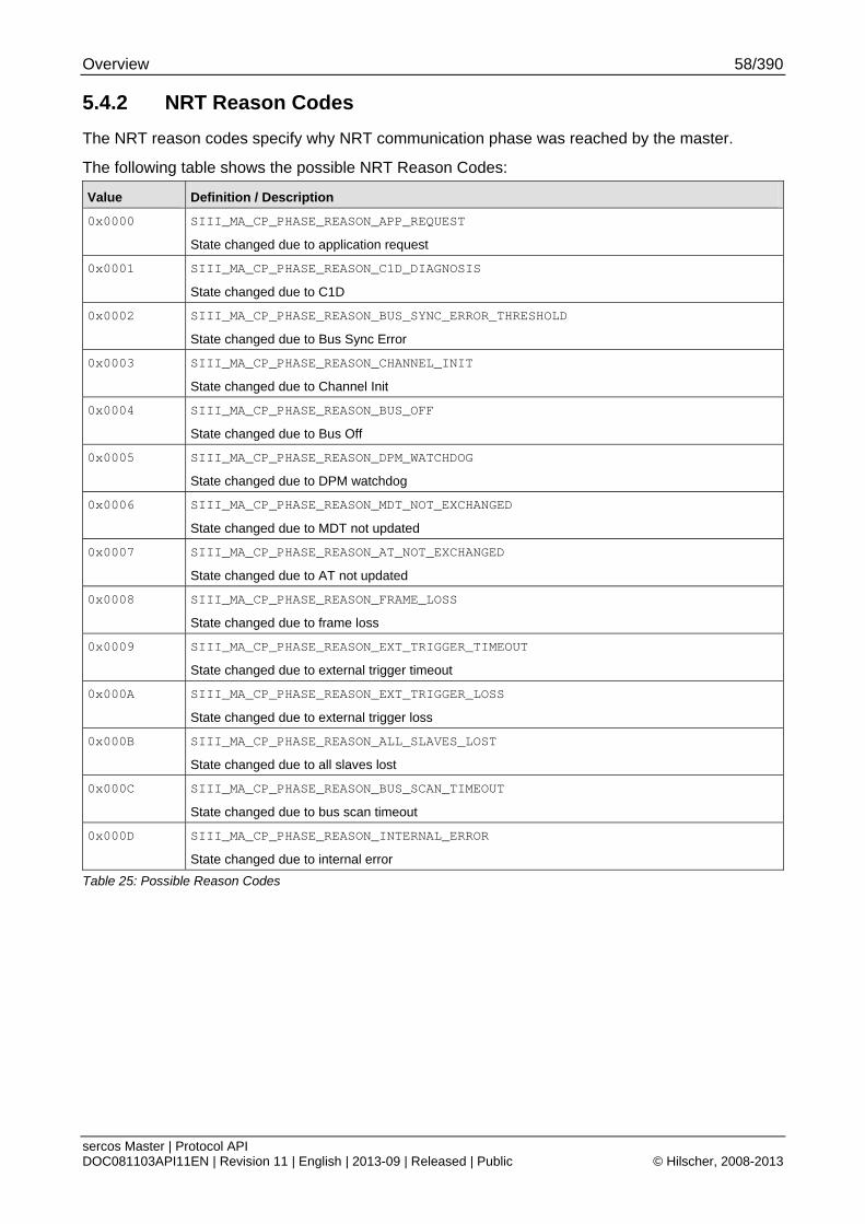
Overview 58/390
sercos Master | Protocol API DOC081103API11EN | Revision 11 | English | 2013-09 | Released | Public © Hilscher, 2008-2013
5.4.2 NRT Reason Codes
The NRT reason codes specify why NRT communication phase was reached by the master.
The following table shows the possible NRT Reason Codes:
Value Definition / Description
0x0000 SIII_MA_CP_PHASE_REASON_APP_REQUEST
State changed due to application request
0x0001 SIII_MA_CP_PHASE_REASON_C1D_DIAGNOSIS
State changed due to C1D
0x0002 SIII_MA_CP_PHASE_REASON_BUS_SYNC_ERROR_THRESHOLD
State changed due to Bus Sync Error
0x0003 SIII_MA_CP_PHASE_REASON_CHANNEL_INIT
State changed due to Channel Init
0x0004 SIII_MA_CP_PHASE_REASON_BUS_OFF
State changed due to Bus Off
0x0005 SIII_MA_CP_PHASE_REASON_DPM_WATCHDOG
State changed due to DPM watchdog
0x0006 SIII_MA_CP_PHASE_REASON_MDT_NOT_EXCHANGED
State changed due to MDT not updated
0x0007 SIII_MA_CP_PHASE_REASON_AT_NOT_EXCHANGED
State changed due to AT not updated
0x0008 SIII_MA_CP_PHASE_REASON_FRAME_LOSS
State changed due to frame loss
0x0009 SIII_MA_CP_PHASE_REASON_EXT_TRIGGER_TIMEOUT
State changed due to external trigger timeout
0x000A SIII_MA_CP_PHASE_REASON_EXT_TRIGGER_LOSS
State changed due to external trigger loss
0x000B SIII_MA_CP_PHASE_REASON_ALL_SLAVES_LOST
State changed due to all slaves lost
0x000C SIII_MA_CP_PHASE_REASON_BUS_SCAN_TIMEOUT
State changed due to bus scan timeout
0x000D SIII_MA_CP_PHASE_REASON_INTERNAL_ERROR
State changed due to internal error
Table 25: Possible Reason Codes
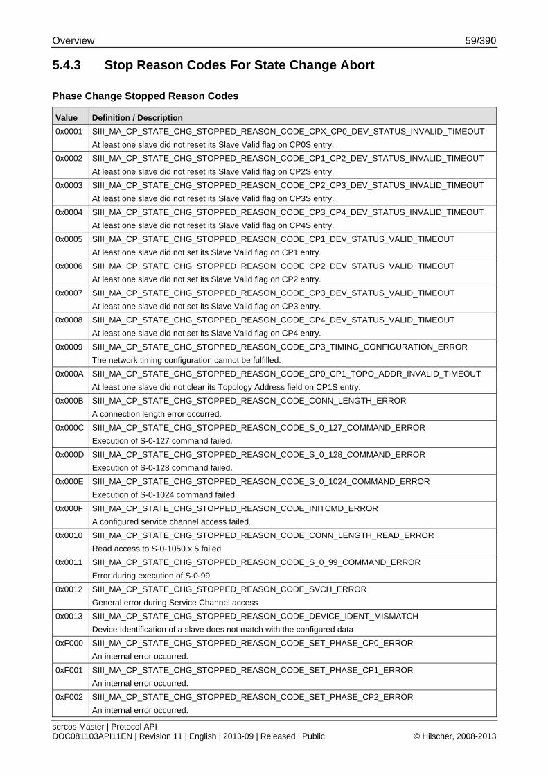
Overview 59/390
sercos Master | Protocol API DOC081103API11EN | Revision 11 | English | 2013-09 | Released | Public © Hilscher, 2008-2013
5.4.3 Stop Reason Codes For State Change Abort
Phase Change Stopped Reason Codes
Value Definition / Description
0x0001 SIII_MA_CP_STATE_CHG_STOPPED_REASON_CODE_CPX_CP0_DEV_STATUS_INVALID_TIMEOUT
At least one slave did not reset its Slave Valid flag on CP0S entry.
0x0002 SIII_MA_CP_STATE_CHG_STOPPED_REASON_CODE_CP1_CP2_DEV_STATUS_INVALID_TIMEOUT
At least one slave did not reset its Slave Valid flag on CP2S entry.
0x0003 SIII_MA_CP_STATE_CHG_STOPPED_REASON_CODE_CP2_CP3_DEV_STATUS_INVALID_TIMEOUT
At least one slave did not reset its Slave Valid flag on CP3S entry.
0x0004 SIII_MA_CP_STATE_CHG_STOPPED_REASON_CODE_CP3_CP4_DEV_STATUS_INVALID_TIMEOUT
At least one slave did not reset its Slave Valid flag on CP4S entry.
0x0005 SIII_MA_CP_STATE_CHG_STOPPED_REASON_CODE_CP1_DEV_STATUS_VALID_TIMEOUT
At least one slave did not set its Slave Valid flag on CP1 entry.
0x0006 SIII_MA_CP_STATE_CHG_STOPPED_REASON_CODE_CP2_DEV_STATUS_VALID_TIMEOUT
At least one slave did not set its Slave Valid flag on CP2 entry.
0x0007 SIII_MA_CP_STATE_CHG_STOPPED_REASON_CODE_CP3_DEV_STATUS_VALID_TIMEOUT
At least one slave did not set its Slave Valid flag on CP3 entry.
0x0008 SIII_MA_CP_STATE_CHG_STOPPED_REASON_CODE_CP4_DEV_STATUS_VALID_TIMEOUT
At least one slave did not set its Slave Valid flag on CP4 entry.
0x0009 SIII_MA_CP_STATE_CHG_STOPPED_REASON_CODE_CP3_TIMING_CONFIGURATION_ERROR
The network timing configuration cannot be fulfilled.
0x000A SIII_MA_CP_STATE_CHG_STOPPED_REASON_CODE_CP0_CP1_TOPO_ADDR_INVALID_TIMEOUT
At least one slave did not clear its Topology Address field on CP1S entry.
0x000B SIII_MA_CP_STATE_CHG_STOPPED_REASON_CODE_CONN_LENGTH_ERROR
A connection length error occurred.
0x000C SIII_MA_CP_STATE_CHG_STOPPED_REASON_CODE_S_0_127_COMMAND_ERROR
Execution of S-0-127 command failed.
0x000D SIII_MA_CP_STATE_CHG_STOPPED_REASON_CODE_S_0_128_COMMAND_ERROR
Execution of S-0-128 command failed.
0x000E SIII_MA_CP_STATE_CHG_STOPPED_REASON_CODE_S_0_1024_COMMAND_ERROR
Execution of S-0-1024 command failed.
0x000F SIII_MA_CP_STATE_CHG_STOPPED_REASON_CODE_INITCMD_ERROR
A configured service channel access failed.
0x0010 SIII_MA_CP_STATE_CHG_STOPPED_REASON_CODE_CONN_LENGTH_READ_ERROR
Read access to S-0-1050.x.5 failed
0x0011 SIII_MA_CP_STATE_CHG_STOPPED_REASON_CODE_S_0_99_COMMAND_ERROR
Error during execution of S-0-99
0x0012 SIII_MA_CP_STATE_CHG_STOPPED_REASON_CODE_SVCH_ERROR
General error during Service Channel access
0x0013 SIII_MA_CP_STATE_CHG_STOPPED_REASON_CODE_DEVICE_IDENT_MISMATCH
Device Identification of a slave does not match with the configured data
0xF000 SIII_MA_CP_STATE_CHG_STOPPED_REASON_CODE_SET_PHASE_CP0_ERROR
An internal error occurred.
0xF001 SIII_MA_CP_STATE_CHG_STOPPED_REASON_CODE_SET_PHASE_CP1_ERROR
An internal error occurred.
0xF002 SIII_MA_CP_STATE_CHG_STOPPED_REASON_CODE_SET_PHASE_CP2_ERROR
An internal error occurred.

Overview 60/390
sercos Master | Protocol API DOC081103API11EN | Revision 11 | English | 2013-09 | Released | Public © Hilscher, 2008-2013
Value Definition / Description
0xF003 SIII_MA_CP_STATE_CHG_STOPPED_REASON_CODE_SET_PHASE_CP3_ERROR
An internal error occurred.
0xF004 SIII_MA_CP_STATE_CHG_STOPPED_REASON_CODE_SET_PHASE_CP4_ERROR
An internal error occurred.
0xF005 SIII_MA_CP_STATE_CHG_STOPPED_REASON_CODE_SET_PHASE_CP0S_ERROR
An internal error occurred.
0xF006 SIII_MA_CP_STATE_CHG_STOPPED_REASON_CODE_SET_PHASE_CP1S_ERROR
An internal error occurred.
0xF007 SIII_MA_CP_STATE_CHG_STOPPED_REASON_CODE_SET_PHASE_CP2S_ERROR
An internal error occurred.
0xF008 SIII_MA_CP_STATE_CHG_STOPPED_REASON_CODE_SET_PHASE_CP3S_ERROR
An internal error occurred.
0xF009 SIII_MA_CP_STATE_CHG_STOPPED_REASON_CODE_SET_PHASE_CP4S_ERROR
An internal error occurred.
0xF00A SIII_MA_CP_STATE_CHG_STOPPED_REASON_CODE_SVC_TASK_COMMUNICATION_ERROR
An internal error occurred. Communication with SVC Task failed.
Table 26: SIII_MA_CP_CMD_STATE_CHG_STOPPED_IND – Phase Change Stopped Reason Codes
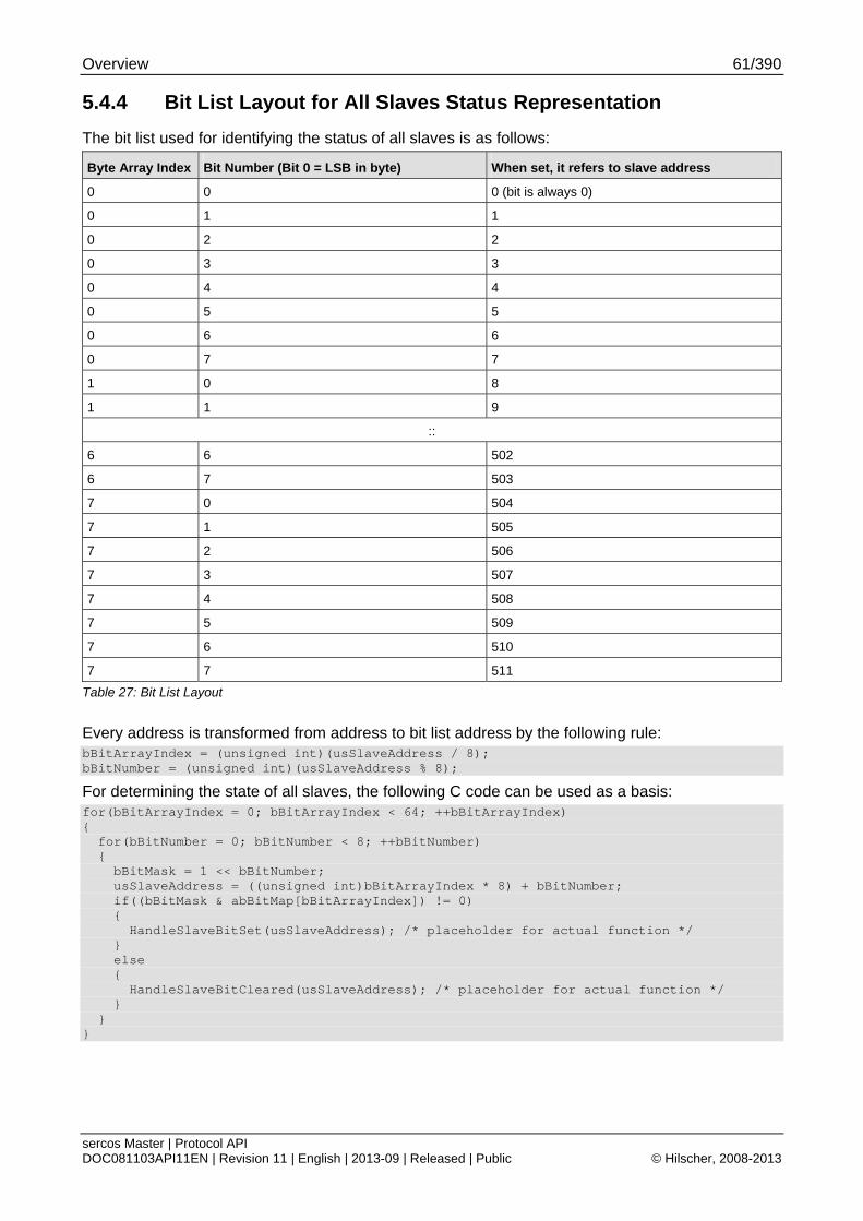
Overview 61/390
sercos Master | Protocol API DOC081103API11EN | Revision 11 | English | 2013-09 | Released | Public © Hilscher, 2008-2013
5.4.4 Bit List Layout for All Slaves Status Representation
The bit list used for identifying the status of all slaves is as follows:
Byte Array Index Bit Number (Bit 0 = LSB in byte) When set, it refers to slave address
0 0 0 (bit is always 0)
0 1 1
0 2 2
0 3 3
0 4 4
0 5 5
0 6 6
0 7 7
1 0 8
1 1 9
::
6 6 502
6 7 503
7 0 504
7 1 505
7 2 506
7 3 507
7 4 508
7 5 509
7 6 510
7 7 511
Table 27: Bit List Layout
Every address is transformed from address to bit list address by the following rule: bBitArrayIndex = (unsigned int)(usSlaveAddress / 8); bBitNumber = (unsigned int)(usSlaveAddress % 8);
For determining the state of all slaves, the following C code can be used as a basis: for(bBitArrayIndex = 0; bBitArrayIndex < 64; ++bBitArrayIndex) { for(bBitNumber = 0; bBitNumber < 8; ++bBitNumber) { bBitMask = 1 << bBitNumber; usSlaveAddress = ((unsigned int)bBitArrayIndex * 8) + bBitNumber; if((bBitMask & abBitMap[bBitArrayIndex]) != 0) { HandleSlaveBitSet(usSlaveAddress); /* placeholder for actual function */ } else { HandleSlaveBitCleared(usSlaveAddress); /* placeholder for actual function */ } } }
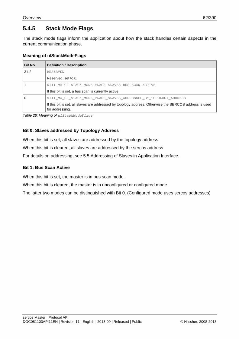
Overview 62/390
sercos Master | Protocol API DOC081103API11EN | Revision 11 | English | 2013-09 | Released | Public © Hilscher, 2008-2013
5.4.5 Stack Mode Flags
The stack mode flags inform the application about how the stack handles certain aspects in the current communication phase.
Meaning of ulStackModeFlags
Bit No. Definition / Description
31-2 RESERVED
Reserved, set to 0.
1 SIII_MA_CP_STACK_MODE_FLAGS_SLAVES_BUS_SCAN_ACTIVE
If this bit is set, a bus scan is currently active.
0 SIII_MA_CP_STACK_MODE_FLAGS_SLAVES_ADDRESSED_BY_TOPOLOGY_ADDRESS
If this bit is set, all slaves are addressed by topology address. Otherwise the SERCOS address is used for addressing.
Table 28: Meaning of ulStackModeFlags
Bit 0: Slaves addressed by Topology Address
When this bit is set, all slaves are addressed by the topology address.
When this bit is cleared, all slaves are addressed by the sercos address.
For details on addressing, see 5.5 Addressing of Slaves in Application Interface.
Bit 1: Bus Scan Active
When this bit is set, the master is in bus scan mode.
When this bit is cleared, the master is in unconfigured or configured mode.
The latter two modes can be distinguished with Bit 0. (Configured mode uses sercos addresses)
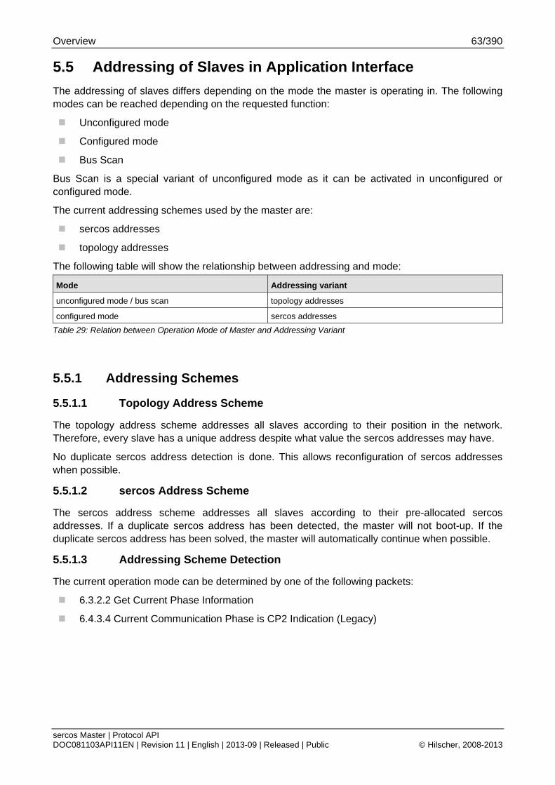
Overview 63/390
sercos Master | Protocol API DOC081103API11EN | Revision 11 | English | 2013-09 | Released | Public © Hilscher, 2008-2013
5.5 Addressing of Slaves in Application Interface
The addressing of slaves differs depending on the mode the master is operating in. The following modes can be reached depending on the requested function:
Unconfigured mode
Configured mode
Bus Scan
Bus Scan is a special variant of unconfigured mode as it can be activated in unconfigured or configured mode.
The current addressing schemes used by the master are:
sercos addresses
topology addresses
The following table will show the relationship between addressing and mode:
Mode Addressing variant
unconfigured mode / bus scan topology addresses
configured mode sercos addresses
Table 29: Relation between Operation Mode of Master and Addressing Variant
5.5.1 Addressing Schemes
5.5.1.1 Topology Address Scheme
The topology address scheme addresses all slaves according to their position in the network. Therefore, every slave has a unique address despite what value the sercos addresses may have.
No duplicate sercos address detection is done. This allows reconfiguration of sercos addresses when possible.
5.5.1.2 sercos Address Scheme
The sercos address scheme addresses all slaves according to their pre-allocated sercos addresses. If a duplicate sercos address has been detected, the master will not boot-up. If the duplicate sercos address has been solved, the master will automatically continue when possible.
5.5.1.3 Addressing Scheme Detection
The current operation mode can be determined by one of the following packets:
6.3.2.2 Get Current Phase Information
6.4.3.4 Current Communication Phase is CP2 Indication (Legacy)
Overview 64/390
sercos Master | Protocol API DOC081103API11EN | Revision 11 | English | 2013-09 | Released | Public © Hilscher, 2008-2013
5.5.2 Operation Modes
5.5.2.1 Unconfigured Mode / Bus-Scan
The unconfigured mode and bus-scan allow an application to operate the master for accessing CP2 including service channels.
5.5.2.2 Configured Mode / Normal startup
The configured mode allows entering all phases since the master has got configuration data for CP3/CP4. If the configuration does not match the connected bus, the master may stop the boot up and notify the application.
Overview 65/390
sercos Master | Protocol API DOC081103API11EN | Revision 11 | English | 2013-09 | Released | Public © Hilscher, 2008-2013
5.6 Procedure Commands
Procedure commands are special IDNs which are used to activate certain functions within a slave via service channel. Due to their longer processing, those procedure commands use the operation data for control and the data status for status information. In addition, the completion - whether successful or not - is signaled via the S-DEV.
5.6.1 Executing Procedure Commands via Svc Macro Functions
The following services are provided for easing the access to the procedure commands a slave provides:
6.8.5.5 Set Procedure Command
6.8.5.6 Clear Procedure Command
6.8.5.7 Read Procedure Command Status
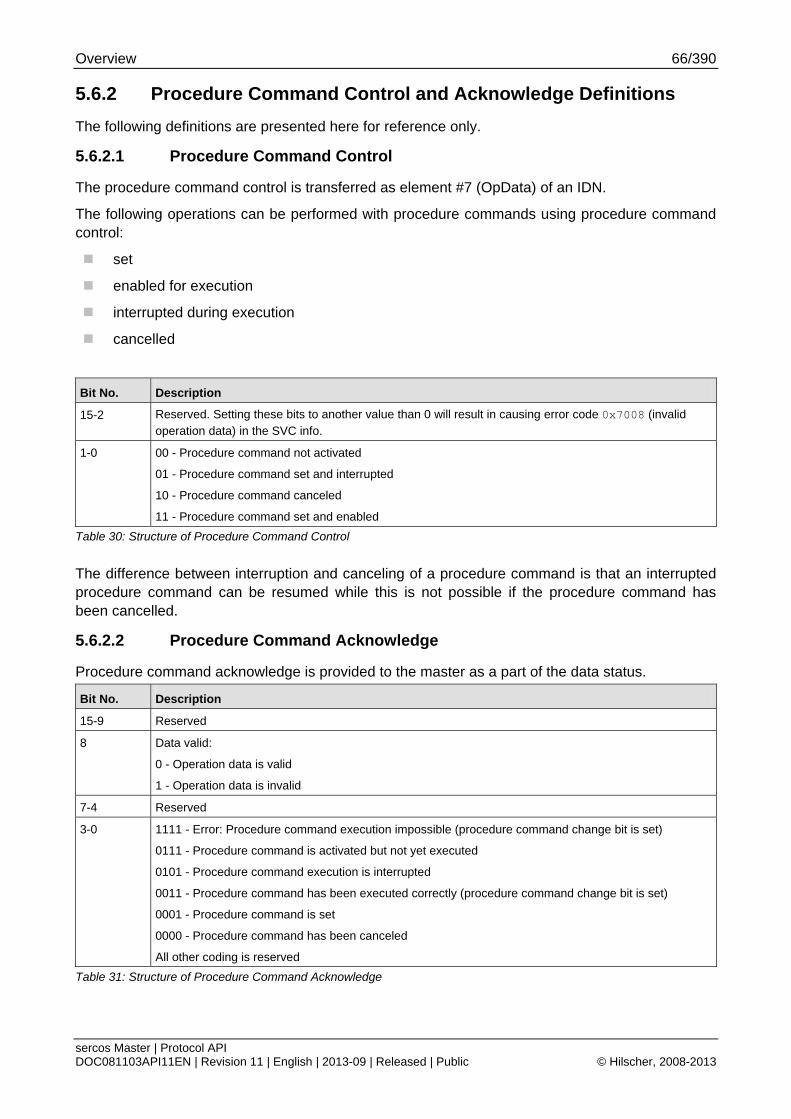
Overview 66/390
sercos Master | Protocol API DOC081103API11EN | Revision 11 | English | 2013-09 | Released | Public © Hilscher, 2008-2013
5.6.2 Procedure Command Control and Acknowledge Definitions
The following definitions are presented here for reference only.
5.6.2.1 Procedure Command Control
The procedure command control is transferred as element #7 (OpData) of an IDN.
The following operations can be performed with procedure commands using procedure command control:
set
enabled for execution
interrupted during execution
cancelled
Bit No. Description
15-2 Reserved. Setting these bits to another value than 0 will result in causing error code 0x7008 (invalid operation data) in the SVC info.
1-0 00 - Procedure command not activated
01 - Procedure command set and interrupted
10 - Procedure command canceled
11 - Procedure command set and enabled
Table 30: Structure of Procedure Command Control
The difference between interruption and canceling of a procedure command is that an interrupted procedure command can be resumed while this is not possible if the procedure command has been cancelled.
5.6.2.2 Procedure Command Acknowledge
Procedure command acknowledge is provided to the master as a part of the data status.
Bit No. Description
15-9 Reserved
8 Data valid:
0 - Operation data is valid
1 - Operation data is invalid
7-4 Reserved
3-0 1111 - Error: Procedure command execution impossible (procedure command change bit is set)
0111 - Procedure command is activated but not yet executed
0101 - Procedure command execution is interrupted
0011 - Procedure command has been executed correctly (procedure command change bit is set)
0001 - Procedure command is set
0000 - Procedure command has been canceled
All other coding is reserved
Table 31: Structure of Procedure Command Acknowledge
Overview 67/390
sercos Master | Protocol API DOC081103API11EN | Revision 11 | English | 2013-09 | Released | Public © Hilscher, 2008-2013
5.6.3 The Procedure Command Change Bit
The Procedure Command Change Bit (PCB) (defined as bit 5 of the Device Status, see section 8.2.1 on page 375 of this document) is used to signal the end of processing a procedure command. It is set only under the following conditions:
Positive Acknowledgment
The procedure command has been executed correctly and successfully.
Negative Acknowledgment
The execution of the procedure command is impossible due to any error.
If at one time more than one procedure command is executed in parallel and the PCB has been set by more than one procedure command, this bit will only be reset within the device status after all procedure commands have been canceled which had set the PCB bit.
Overview 68/390
sercos Master | Protocol API DOC081103API11EN | Revision 11 | English | 2013-09 | Released | Public © Hilscher, 2008-2013
5.7 Diagnosis
The following diagnostic capabilities are provided by the sercos Master protocol stack:
Diagnostic Log
Provides access to sercos-specific diagnostic events
Get Bus Info
Bus scan
Extended Status
Slave Diagnostic Information
5.7.1 Slave Diagnostic Information
The slave diagnostic information provides status information on what happened at each slave specifically.
For details, see 6.10 Retrieval of Slave Diagnostic Information.
5.7.2 Diagnostic Log
The sercos Master protocol stack allows the application to be informed about various events such as:
Change of communication phase
Failure of Init command
Failure or warning in slave
Bus on/bus off
Channel init
DPM watchdog error
Change in topology
Hot-plug events
Bus scan
Internal error
Connection length Error (IDN S-0-1050.x.5)
For details about how to use the diagnostic log, see chapter 6.5 Diagnostic Log.
Overview 69/390
sercos Master | Protocol API DOC081103API11EN | Revision 11 | English | 2013-09 | Released | Public © Hilscher, 2008-2013
5.7.3 C1D and C2D
C1D and C2D diagnostic events state whether a slave has detected a problem. However, those events do not necessarily prevent the master from reaching CP4.
The C1D and C2D diagnostic events are for diagnosing slave specific issues.
For diagnosing boot up problems, the following services are more suitable:
6.3.2.2 Get Current Phase Information Service
6.4.2.1 Current Communication Phase Indication (since V2.1.X)
Note: The C1D and C2D diagnostics do not provide full boot up diagnostic from the master point of view.
5.7.3.1 Class 1 Diagnostic (C1D)
A Class 1 Diagnostic notifies the master about an error in the slave which prevents or prevented it from normal operation.
Note: To clear those errors, the application has to issue the procedure command ‘Reset Class 1 Diagnostic’ (IDN S-0-0099). When no error at the slave is present, the C1D will not be set again.
5.7.3.2 Class 2 Diagnostic (C2D)
A Class 2 Diagnostic notifies the master about a warning in the slave which may prevent it from normal operation.
5.7.4 Bus Scan
Bus scan provides the possibility to scan the network for available slaves. The bus scan request overrides the configured mode and switches the master internally to a similar operation mode as the unconfigured mode.
After the bus scan request has completed, the bus scan results can be read from all connected slaves.
For details on using bus scan, see chapter 6.11 Bus Scan
Overview 70/390
sercos Master | Protocol API DOC081103API11EN | Revision 11 | English | 2013-09 | Released | Public © Hilscher, 2008-2013
5.8 Ring Topology and Ring Healing
The ring topology offers cable redundancy during communication. A single cable can be damaged or removed. The communication is able to continue without leaving real-time requirements (e.g. synchronization).
General operation
When the cable connection between the involved slaves is re-established, the master will detect that the ring is healable. The topology state machine of the master will attempt a ring healing. If the ring healing is processed successfully, the ring redundancy has been re-established.
If one or both involved slaves cannot switch their topology to ring, the master will consider the ring healing as failed. In that case, the ring redundancy cannot be re-established.
Recording of events within diagnostic log
The diagnostic log will record any of those events. For details, see 5.7.2 Diagnostic Log.
Operation Modes of Ring Healing
The master offers two modes for ring healing: automatic or manual.
The automatic mode is the default case. This mode is suitable for most use cases.
For those applications needing manual ring healing, see 6.12 Manual Ring Healing Control.
5.9 Hot Plug (since V2.1.X)
The master supports hot plugging of sercos slaves which allows connecting slaves into a running network when supported by the slave.
To determine errors during hot plugging, the master uses the following functionalities:
5.7.2 Diagnostic Log
6.4.2.2 Slaves Valid Indication Service (since V2.1.X)
6.9 Hot Plug (since V2.1.X)
6.9.2 Hot Plug Error Acknowledgement Service
When an error occurs during hot plugging, the master requires acknowledgement of the error. Until that acknowledgement, the master will temporarily disable the hot plug functionality in order to prevent cyclic activation and to be able present the error information.
Overview 71/390
sercos Master | Protocol API DOC081103API11EN | Revision 11 | English | 2013-09 | Released | Public © Hilscher, 2008-2013
5.10 Process Data
The process data image contains connection control (C-CON) and real-time data of every available master-to-slave and slave-to-master connection. Every connection has a connection control and real-time data.
For SYCON.net configured process data layout, see 5.10.1.2 SYCON.net configured Process Data Image Layout.
For packet configuration, see 6.1.2 Process Data Image Layout Configuration.
5.10.1 Connection Control (C-CON)
The connection control controls the state of the connection and signals updates to the consumer.
Bit No. Value Description Comments
15-12 Counter (sercos V1.3) For description see 5.10.1.1 New Data Toggle and Counter
Bit 12 is mirrored as Bit 1
11-8 reserved
7 Real-time bit 2
6 Real-time bit 1
5 reserved
4 Flow Control (sercos V1.3) 0 = run
1 = stop
Producer synchronization
0 not synchronized Producer is not synchronous with the synchronization reference time (TSref)
3
1 synchronized Producer is synchronous with the synchronization reference time (TSref)
Data field delay The consumer shall prefer taking the data of the port at which this bit has the value 0.
0 No delay Data is transmitted without delay in the same SERCOS cycle.
2
1 delay Master has copied the data. Data is delayed by one additional cycle.
New data New producer data 1
toggle For description see 5.10.1.1 New Data Toggle and Counter
Producer ready
0 not valid The producer does not generate any data in this connection yet
0
1 valid The producer generates data in this connection. The consumer can process the connection data if the producer has toggled the New data (bit 1). The producer ready bit shall be evaluated in CP4 only.
Table 32: Connection Control
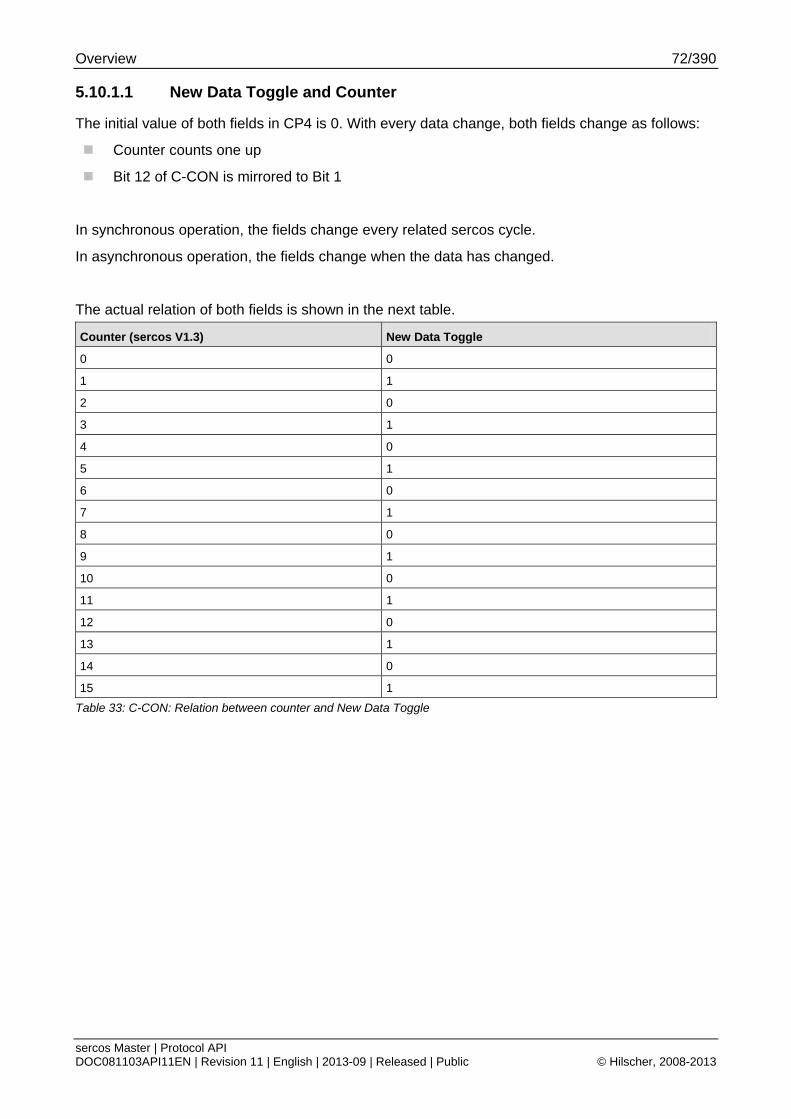
Overview 72/390
sercos Master | Protocol API DOC081103API11EN | Revision 11 | English | 2013-09 | Released | Public © Hilscher, 2008-2013
5.10.1.1 New Data Toggle and Counter
The initial value of both fields in CP4 is 0. With every data change, both fields change as follows:
Counter counts one up
Bit 12 of C-CON is mirrored to Bit 1
In synchronous operation, the fields change every related sercos cycle.
In asynchronous operation, the fields change when the data has changed.
The actual relation of both fields is shown in the next table.
Counter (sercos V1.3) New Data Toggle
0 0
1 1
2 0
3 1
4 0
5 1
6 0
7 1
8 0
9 1
10 0
11 1
12 0
13 1
14 0
15 1
Table 33: C-CON: Relation between counter and New Data Toggle
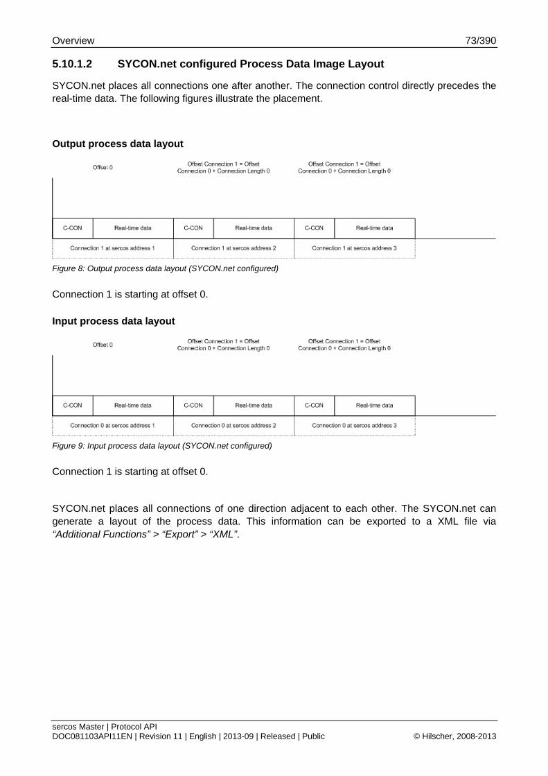
Overview 73/390
sercos Master | Protocol API DOC081103API11EN | Revision 11 | English | 2013-09 | Released | Public © Hilscher, 2008-2013
5.10.1.2 SYCON.net configured Process Data Image Layout
SYCON.net places all connections one after another. The connection control directly precedes the real-time data. The following figures illustrate the placement.
Output process data layout
Figure 8: Output process data layout (SYCON.net configured)
Connection 1 is starting at offset 0.
Input process data layout
Figure 9: Input process data layout (SYCON.net configured)
Connection 1 is starting at offset 0.
SYCON.net places all connections of one direction adjacent to each other. The SYCON.net can generate a layout of the process data. This information can be exported to a XML file via “Additional Functions” > “Export” > “XML”.
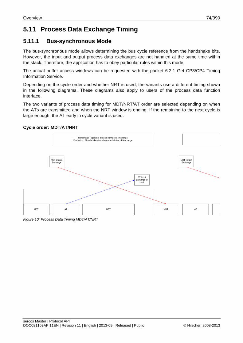
Overview 74/390
sercos Master | Protocol API DOC081103API11EN | Revision 11 | English | 2013-09 | Released | Public © Hilscher, 2008-2013
5.11 Process Data Exchange Timing
5.11.1 Bus-synchronous Mode
The bus-synchronous mode allows determining the bus cycle reference from the handshake bits. However, the input and output process data exchanges are not handled at the same time within the stack. Therefore, the application has to obey particular rules within this mode.
The actual buffer access windows can be requested with the packet 6.2.1 Get CP3/CP4 Timing Information Service.
Depending on the cycle order and whether NRT is used, the variants use a different timing shown in the following diagrams. These diagrams also apply to users of the process data function interface.
The two variants of process data timing for MDT/NRT/AT order are selected depending on when the ATs are transmitted and when the NRT window is ending. If the remaining to the next cycle is large enough, the AT early in cycle variant is used.
Cycle order: MDT/AT/NRT
Figure 10: Process Data Timing MDT/AT/NRT
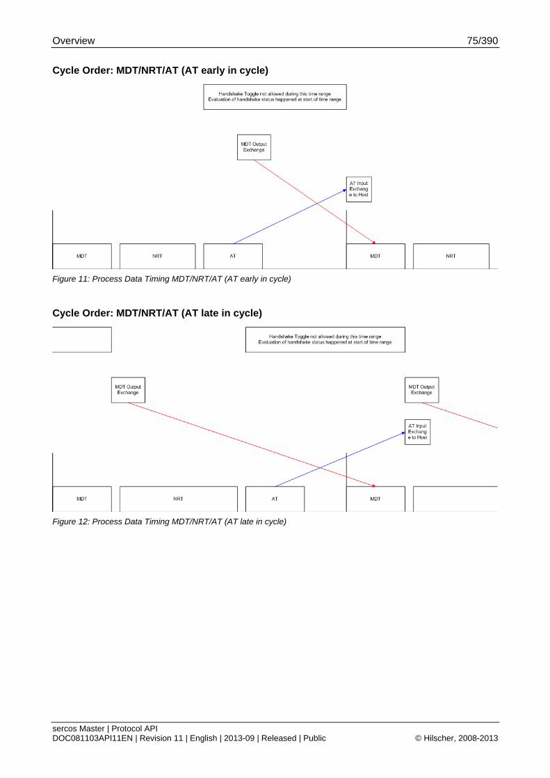
Overview 75/390
sercos Master | Protocol API DOC081103API11EN | Revision 11 | English | 2013-09 | Released | Public © Hilscher, 2008-2013
Cycle Order: MDT/NRT/AT (AT early in cycle)
Figure 11: Process Data Timing MDT/NRT/AT (AT early in cycle)
Cycle Order: MDT/NRT/AT (AT late in cycle)
Figure 12: Process Data Timing MDT/NRT/AT (AT late in cycle)
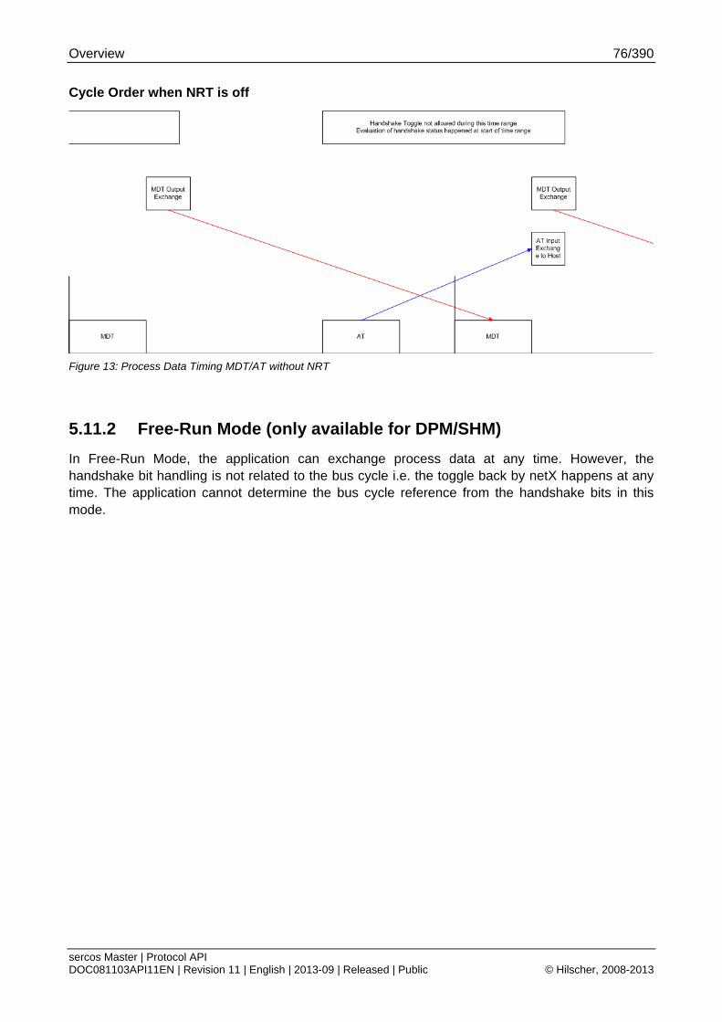
Overview 76/390
sercos Master | Protocol API DOC081103API11EN | Revision 11 | English | 2013-09 | Released | Public © Hilscher, 2008-2013
Cycle Order when NRT is off
Figure 13: Process Data Timing MDT/AT without NRT
5.11.2 Free-Run Mode (only available for DPM/SHM)
In Free-Run Mode, the application can exchange process data at any time. However, the handshake bit handling is not related to the bus cycle i.e. the toggle back by netX happens at any time. The application cannot determine the bus cycle reference from the handshake bits in this mode.
Overview 77/390
sercos Master | Protocol API DOC081103API11EN | Revision 11 | English | 2013-09 | Released | Public © Hilscher, 2008-2013
5.12 NRT Channel Behavior
The NRT channel behaves similar to an Ethernet switch. However, it is additionally controlled by ring detection mechanisms whether forwarding between both sercos ports is done.
5.12.1 Routing Behavior
Behavior on known MAC addresses
In case of a ring, the forwarding between the sercos ports will be disabled, only forwarding between the internal Ethernet interface and one of the two sercos ports will be done depending on where the current MAC address is received from.
In case of a line or two lines, all forwarding paths are enabled and will be used depending on where the current MAC address is received from.
Behavior on unknown MAC addresses
In case of a ring, the frame will be sent via one port only since every slave can be reached independent of what port is used.
In case of two lines, the frame will be sent to all ports since the current position is not yet known.
Behavior of internal port of NRT frame routing
The implemented switch behavior is checking the destination MAC address of received NRT frames for one of the following conditions:
Own configured unicast MAC address
Check can be disabled by switching promiscuous mode on
(see 6.13 NRT Promiscuous Control)
Multicast MAC address
Broadcast MAC address
If the frame does not match any of these conditions, it will be only forwarded to the other port or discarded depending on the current ring status and where the MAC address is known to be on.
5.12.2 Ring Detection
The ring detection is done in two different ways depending on the current communication phase.
In NRT phase, the master uses beacon frames to detect whether a ring exists.
In CP0, the master derives the ring status from the reception of the sercos frames.
In any other phase, the master derives the ring status from the S-DEV of the slaves and its internal status.
Note: NRT ring is closed before the actual ring healing takes place. Therefore, the master checks the inactive port status as well to determine the NRT ring status.
A change of the ring healing results into a reset of the MAC address table and the learning of the MAC addresses is started all over.
Overview 78/390
sercos Master | Protocol API DOC081103API11EN | Revision 11 | English | 2013-09 | Released | Public © Hilscher, 2008-2013
5.13 NRT Channel Access on DPM
The NRT channel can be accessed via Ethernet interface on second communication channel when available in the firmware. The application interface of the Ethernet interface is described in the Ethernet Protocol Interface Manual” [5].
The Application Interface 79/390
sercos Master | Protocol API DOC081103API11EN | Revision 11 | English | 2013-09 | Released | Public © Hilscher, 2008-2013
6 The Application Interface This chapter defines the application interface of the master stack.
The following service categories are supported:
6.1 Configuration Data Packets
6.2 Configuration Information Readout
6.3 Phase Control
6.4 Status Indications
6.5 Diagnostic Log
6.6 Slave Identification Services
6.7 Controlling the C-DEV Ident Request Bit
6.8 Service Channel Access
6.10 Retrieval of Slave Diagnostic Information
The common part of this service is specified within the netX DPM Interface Manual.
The sercos specific part is shown in the mentioned chapter.
6.11 Bus Scan
6.12 Manual Ring Healing Control
The Application Interface 80/390
sercos Master | Protocol API DOC081103API11EN | Revision 11 | English | 2013-09 | Released | Public © Hilscher, 2008-2013
6.1 Configuration Data Packets
6.1.1 Auto Configuration Service
The Auto Configuration service allows configuring the master without a configurator such as SYCON.net. However, due to the defined rules for Auto Configuration, the Auto Configuration will not replace a full-featured configurator.
The automatic configuration allows configuring a network by applying bus scan. The detected slaves will be configured according to the following rules:
FSP_IO with SCP_FixCFG
This type of slave is always configured for bus coupler container configuration. The master will read out the resulting connection length.
FSP_IO with SCP_VarCFG
The sercos master will configure the slave to use container configuration and then read out the resulting connection lengths.
FSP_Drive with SCP_VarCFG
This type of slave will be configured for velocity mode.
The Auto Configuration service reuses the following existing mechanisms to provide its functions:
6.11 “Bus Scan”
6.1.7 “Automatic Configuration of Frame Layout with automatic Timing Calculation”
6.1.8“Automatic Configuration of Frame Layout with user specified Timing Parameters”
These services are the foundation for the Auto Configuration service. By combining these services within the service described in this chapter, the application can configure the connected network with a single request applying the aforementioned rules how the configuration is generated.
The Auto Configure service will try to solve duplicate and invalid sercos addresses by assigning new addresses to the slaves. If the addresses are unique and valid, the master will not change them and continue to use them.
The automatically determined process data image layout can be read with services described in chapter 6.2 “Configuration Information Readout”
For detailed parameter description except tAPParam, see 6.1.6.1 “Begin a new Configuration Transfer Service”.
For tAPParam, see 6.1.6.7 “DPM Configuration Service”.
Note: In ulStackConfigurationFlags: the flag MSK_SIII_MA_CP_USE_AUTOCFG_CALCULATION must always be set. Otherwise, the packet will be returned with an error.
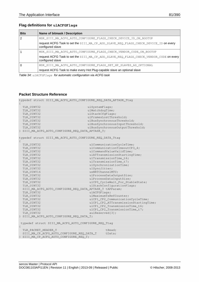
The Application Interface 81/390
sercos Master | Protocol API DOC081103API11EN | Revision 11 | English | 2013-09 | Released | Public © Hilscher, 2008-2013
Flag definitions for ulACFGFlags
Bits Name of bitmask / Description
2 MSK_SIII_MA_ACFG_AUTO_CONFIGURE_FLAGS_CHECK_DEVICE_ID_ON_BOOTUP
request ACFG Task to set the SIII_MA_CP_ADD_SLAVE_REQ_FLAGS_CHECK_DEVICE_ID on every configured slave
1 MSK_SIII_MA_ACFG_AUTO_CONFIGURE_FLAGS_CHECK_VENDOR_CODE_ON_BOOTUP
request ACFG Task to set the SIII_MA_CP_ADD_SLAVE_REQ_FLAGS_CHECK_VENDOR_CODE on every configured slave
0 MSK_SIII_MA_ACFG_AUTO_CONFIGURE_FLAGS_SET_HP_SLAVES_AS_OPTIONAL
request ACFG Task to make every Hot Plug-capable slave an optional slave
Table 34: ulACFGFlags for automatic configuration via ACFG task
Packet Structure Reference
typedef struct SIII_MA_ACFG_AUTO_CONFIGURE_REQ_DATA_APTASK_Ttag { TLR_UINT32 ulSystemFlags; TLR_UINT32 ulWatchdogTime; TLR_UINT32 ulStackCfgFlags; TLR_UINT32 ulFramesLostThreshold; TLR_UINT32 ulBusSynchronousThreshold; TLR_UINT32 ulBusSynchronousInputThreshold; TLR_UINT32 ulBusSynchronousOutputThreshold; } SIII_MA_ACFG_AUTO_CONFIGURE_REQ_DATA_APTASK_T; typedef struct SIII_MA_ACFG_AUTO_CONFIGURE_REQ_DATA_Ttag { TLR_UINT32 ulCommunicationCycleTime; TLR_UINT32 ulCommunicationTimeoutCP3_4; TLR_UINT32 ulCommandValueValidTime; TLR_UINT32 ulATTransmissionStartingTime; TLR_UINT32 ulTransmissionTime_t6; TLR_UINT32 ulTransmissionTime_t7; TLR_UINT32 ulSynchronizationTime; TLR_UINT32 ulSyncJitter; TLR_UINT16 usNRTChannelMTU; TLR_UINT32 ulProcessDataOutputSize; TLR_UINT32 ulProcessDataInputSize; TLR_UINT32 ulCP0_CycleWait_For_StableState; TLR_UINT32 ulStackConfigurationFlags; SIII_MA_ACFG_AUTO_CONFIGURE_REQ_DATA_APTASK_T tAPParam; TLR_UINT32 ulACFGFlags; TLR_UINT32 ulMaximumTsRefCounter; TLR_UINT32 ulCP1_CP2_CommunicationCycleTime; TLR_UINT32 ulCP1_CP2_ATTransmissionStartingTime; TLR_UINT32 ulCP1_CP2_TransmissionTime_t6; TLR_UINT32 ulCP1_CP2_TransmissionTime_t7; TLR_UINT32 aulReserved[3]; } SIII_MA_ACFG_AUTO_CONFIGURE_REQ_DATA_T; typedef struct SIII_MA_ACFG_AUTO_CONFIGURE_REQ_Ttag { TLR_PACKET_HEADER_T tHead; SIII_MA_CP_ACFG_AUTO_CONFIGURE_REQ_DATA_T tData; } SIII_MA_CP_ACFG_AUTO_CONFIGURE_REQ_T;

The Application Interface 82/390
sercos Master | Protocol API DOC081103API11EN | Revision 11 | English | 2013-09 | Released | Public © Hilscher, 2008-2013
Packet Description
Structure SIII_MA_ACFG_AUTO_CONFIGURE_REQ_T Type: Request
Variable Type Value /
Range
Description
tHead - Structure TLR_PACKET_HEADER_T
ulDest UINT32 Destination Queue-Handle
ulSrc UINT32 Source Queue-Handle
ulDestId UINT32 Destination End Point Identifier, specifying the final receiver of the packet within the Destination Process. Set to 0 for the Initialization Packet
ulSrcId UINT32 Source End Point Identifier, specifying the origin of the packet inside the Source Process
ulLen UINT32 114 Packet Data Length in bytes
ulId UINT32 0 ... 232-1 Packet Identification as unique number generated by the Source Process of the Packet
ulSta UINT32 See section Status/Error Codes Overview
ulCmd UINT32 0x8A00 SIII_MA_ACFG_CMD_AUTO_CONFIGURE_REQ - Command
ulExt UINT32 0 Extension, reserved
ulRout UINT32 x Routing, do not touch
tData - Structure SIII_MA_CP_BEGIN_CONFIGURATION_REQ_DATA_T
ulCommunicationCycleTime UINT32 31 250 … 65 000 000
Communication Cycle Time (CP3/4)
For a list of the allowed values see section 4.2.3.1. Do not choose values lower than the minimum cycle time of 250 µs, see section 1.5.1 “Technical Data”.
ulCommunicationTimeoutCP3_4
UINT32 range depends on slave
Communication Timeout (CP3/4)
ulCommandValueValidTime UINT32 0…tScyc Command value valid time (t3)
ulATTransmissionStartingTime
UINT32 0…tScyc AT Transmission Starting Time
ulTransmissionTime_t6 UINT32 0…tScyc NRT transmission time (t6)
ulTransmissionTime_t7 UINT32 0…tScyc NRT transmission time (t7)
ulSynchronizationTime UINT32 0…tScyc Feedback acquisition capture point (Synchronization time) (t4)
ulSyncJitter UINT32 Maximum Value
tScyc / 2
Sync Jitter (internally calculated since V2.1.X)
usNRTChannelMTU UINT16 46…1500
depends on Communication Phase
NRT channel MTU
ulProcessDataOutputSize UINT32 0 … 5760
(Only even values!)
Process Data Output Size (MDT)
Important: Do not specify odd values for the Process Data
Output Size!
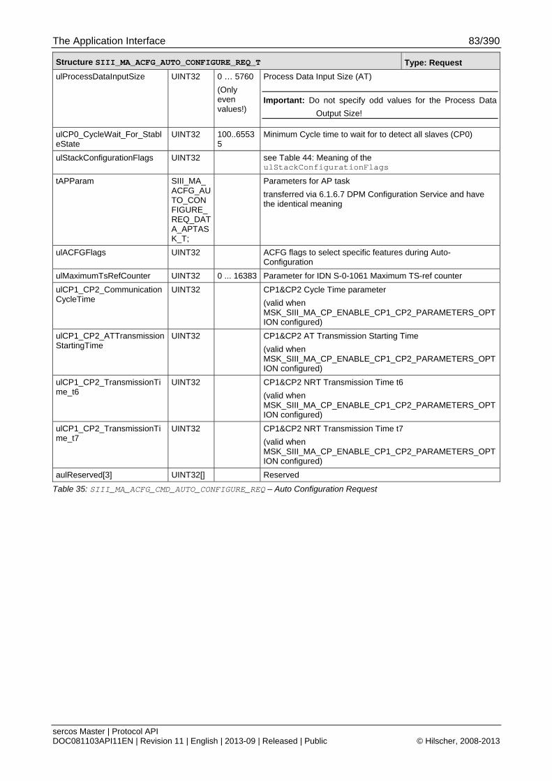
The Application Interface 83/390
sercos Master | Protocol API DOC081103API11EN | Revision 11 | English | 2013-09 | Released | Public © Hilscher, 2008-2013
Structure SIII_MA_ACFG_AUTO_CONFIGURE_REQ_T Type: Request
ulProcessDataInputSize UINT32 0 … 5760
(Only even values!)
Process Data Input Size (AT)
Important: Do not specify odd values for the Process Data
Output Size!
ulCP0_CycleWait_For_StableState
UINT32 100..65535
Minimum Cycle time to wait for to detect all slaves (CP0)
ulStackConfigurationFlags UINT32 see Table 44: Meaning of the ulStackConfigurationFlags
tAPParam SIII_MA_ACFG_AUTO_CONFIGURE_REQ_DATA_APTASK_T;
Parameters for AP task
transferred via 6.1.6.7 DPM Configuration Service and have the identical meaning
ulACFGFlags UINT32 ACFG flags to select specific features during Auto-Configuration
ulMaximumTsRefCounter UINT32 0 ... 16383 Parameter for IDN S-0-1061 Maximum TS-ref counter
ulCP1_CP2_CommunicationCycleTime
UINT32 CP1&CP2 Cycle Time parameter
(valid when MSK_SIII_MA_CP_ENABLE_CP1_CP2_PARAMETERS_OPTION configured)
ulCP1_CP2_ATTransmissionStartingTime
UINT32 CP1&CP2 AT Transmission Starting Time
(valid when MSK_SIII_MA_CP_ENABLE_CP1_CP2_PARAMETERS_OPTION configured)
ulCP1_CP2_TransmissionTime_t6
UINT32 CP1&CP2 NRT Transmission Time t6
(valid when MSK_SIII_MA_CP_ENABLE_CP1_CP2_PARAMETERS_OPTION configured)
ulCP1_CP2_TransmissionTime_t7
UINT32 CP1&CP2 NRT Transmission Time t7
(valid when MSK_SIII_MA_CP_ENABLE_CP1_CP2_PARAMETERS_OPTION configured)
aulReserved[3] UINT32[] Reserved
Table 35: SIII_MA_ACFG_CMD_AUTO_CONFIGURE_REQ – Auto Configuration Request

The Application Interface 84/390
sercos Master | Protocol API DOC081103API11EN | Revision 11 | English | 2013-09 | Released | Public © Hilscher, 2008-2013
Packet Structure Reference
typedef struct SIII_MA_CP_AUTO_CONFIGURE_CNF_Ttag { TLR_PACKET_HEADER_T tHead; } SIII_MA_CP_AUTO_CONFIGURE_CNF_T;
Packet Description
Structure SIII_MA_CP_AUTO_CONFIGURE_CNF_T Type: Confirmation
Variable Type Value / Range Description
tHead - Structure TLR_PACKET_HEADER_T
ulDest UINT32 Destination queue handle, unchanged
ulSrc UINT32 Source queue handle, unchanged
ulDestId UINT32 Destination End Point Identifier, specifying the final receiver of the packet within the Destination Process. Set to 0 for the Initialization Packet
ulSrcId UINT32 Source End Point Identifier, specifying the origin of the packet inside the Source Process
ulLen UINT32 0 Packet Data Length in bytes
ulId UINT32 0 ... 232-1 Packet Identification as unique number generated by the Source Process of the Packet
ulSta UINT32 See section Status/Error Codes Overview
ulCmd UINT32 0x8A01 SIII_MA_ACFG_CMD_AUTO_CONFIGURE_CNF - Command
ulExt UINT32 0 Extension not in use, set to zero for compatibility reasons
ulRout UINT32 x Routing, do not touch
Table 36: SIII_MA_CP_CMD_AUTO_CONFIGURE_CNF Auto Configuration Confirmation
The Application Interface 85/390
sercos Master | Protocol API DOC081103API11EN | Revision 11 | English | 2013-09 | Released | Public © Hilscher, 2008-2013
6.1.2 Process Data Image Layout Configuration
The output process data image contains data from all master-to-slave connections (connection control and real-time data). The input process data image contains data from all slave-to-master connections (connection control and real-time data).
Note: The configured data elements should not overlap since this may have unforeseen consequences.
6.1.2.1 Connection Controls
The connection controls can be freely placed into the process data image at any two-byte aligned offset. They do not have to be placed adjacent to their associated real-time data.
6.1.2.2 Real-time data
The real-time data contains the current data of the connection. Every connection’s real-time data can be placed at any two-byte aligned offset.
The real-time data of a connection is placed as a single block. It is not considered dividable by the master.

The Application Interface 86/390
sercos Master | Protocol API DOC081103API11EN | Revision 11 | English | 2013-09 | Released | Public © Hilscher, 2008-2013
6.1.3 Connection Control Handling Configuration (since V2.1.X)
The following bits in ulStackConfigurationFlags configure the connection control handling:
Bits Name of bitmask / Description
7 MSK_SIII_MA_CP_ENABLE_INTERNAL_CCON_VALID
Enable internal connection-control valid handling
6 MSK_SIII_MA_CP_ENABLE_INTERNAL_SYNC_CCON
Enable internal synchronous connection-control handling
Table 37: Bits in ulStackConfigurationFlags for Configuration of the Connection Control Handling
The master supports three modes of connection control handling:
Application-oriented connection control (only mode in prior versions)
(Bits 6 and 7 are cleared)
Internal synchronous C-CON handling with application controlled Data Valid
(Bit 6 is set and Bit 7 is cleared)
Internal synchronous C-CON handling with internal Data Valid
(Bits 6 and 7 are set)
Note: When Bit 6 is cleared, Bit 7 is ignored.
Application-oriented connection control
This mode is the only supported C-CON handling in versions prior to sercos Master protocol stack V2.1.X.
For synchronous operation, the application must run synchronously to the master.
The following table explains what part of the C-CON controls which items in this mode:
Bit No. Value Description controlled by
15-12 Counter (sercos V1.3) application
11-8 reserved application
7 Real-time bit 2 application
6 Real-time bit 1 application
5 reserved application
4 Flow Control (sercos V1.3) application
3 Producer synchronization application
2 Data field delay master
1 New data application
0 Producer ready application
Table 38: Connection Control in application-oriented C-CON Handling
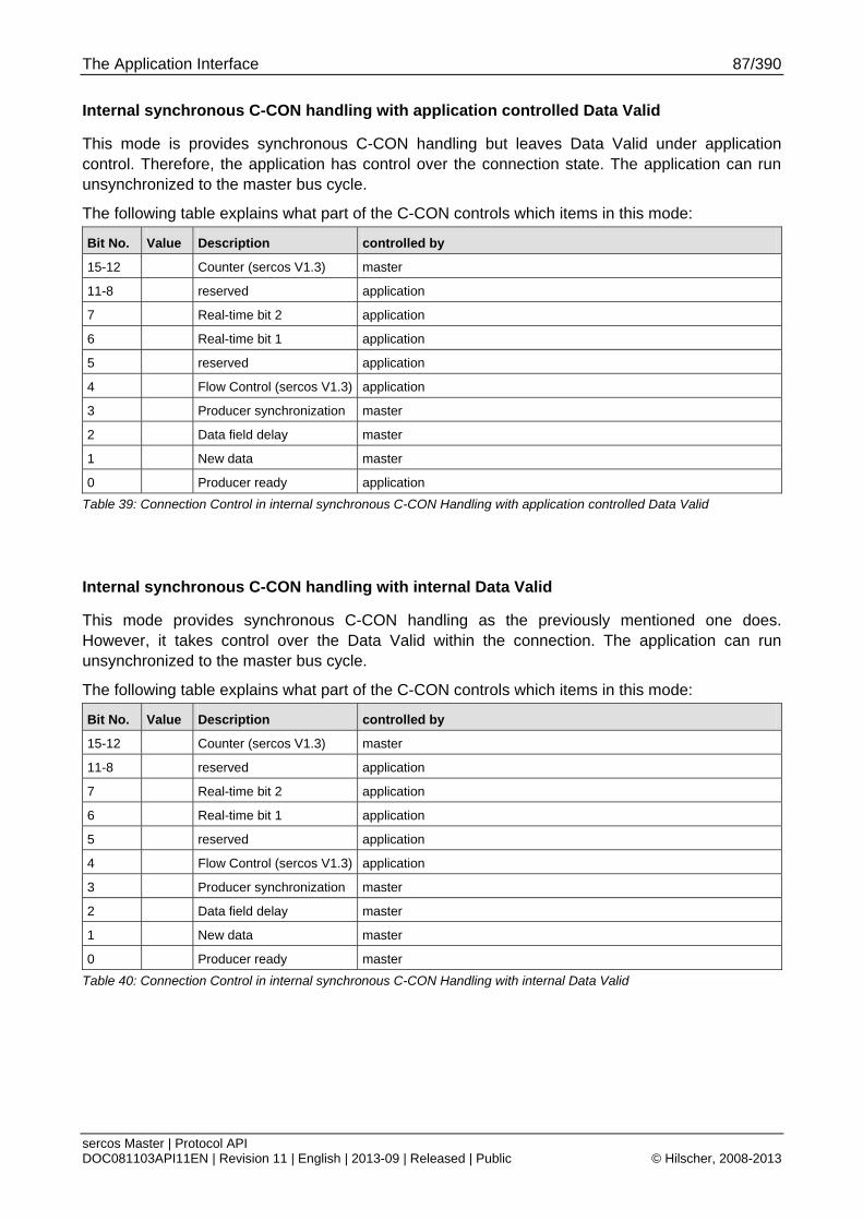
The Application Interface 87/390
sercos Master | Protocol API DOC081103API11EN | Revision 11 | English | 2013-09 | Released | Public © Hilscher, 2008-2013
Internal synchronous C-CON handling with application controlled Data Valid
This mode is provides synchronous C-CON handling but leaves Data Valid under application control. Therefore, the application has control over the connection state. The application can run unsynchronized to the master bus cycle.
The following table explains what part of the C-CON controls which items in this mode:
Bit No. Value Description controlled by
15-12 Counter (sercos V1.3) master
11-8 reserved application
7 Real-time bit 2 application
6 Real-time bit 1 application
5 reserved application
4 Flow Control (sercos V1.3) application
3 Producer synchronization master
2 Data field delay master
1 New data master
0 Producer ready application
Table 39: Connection Control in internal synchronous C-CON Handling with application controlled Data Valid
Internal synchronous C-CON handling with internal Data Valid
This mode provides synchronous C-CON handling as the previously mentioned one does. However, it takes control over the Data Valid within the connection. The application can run unsynchronized to the master bus cycle.
The following table explains what part of the C-CON controls which items in this mode:
Bit No. Value Description controlled by
15-12 Counter (sercos V1.3) master
11-8 reserved application
7 Real-time bit 2 application
6 Real-time bit 1 application
5 reserved application
4 Flow Control (sercos V1.3) application
3 Producer synchronization master
2 Data field delay master
1 New data master
0 Producer ready master
Table 40: Connection Control in internal synchronous C-CON Handling with internal Data Valid
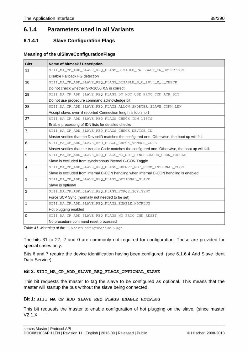
The Application Interface 88/390
sercos Master | Protocol API DOC081103API11EN | Revision 11 | English | 2013-09 | Released | Public © Hilscher, 2008-2013
6.1.4 Parameters used in all Variants
6.1.4.1 Slave Configuration Flags
Meaning of the ulSlaveConfigurationFlags
Bits Name of bitmask / Description
31 SIII_MA_CP_ADD_SLAVE_REQ_FLAGS_DISABLE_FALLBACK_FG_DETECTION
Disable Fallback FG detection
30 SIII_MA_CP_ADD_SLAVE_REQ_FLAGS_DISABLE_S_0_1050_X_5_CHECK
Do not check whether S-0-1050.X.5 is correct.
29 SIII_MA_CP_ADD_SLAVE_REQ_FLAGS_DO_NOT_USE_PROC_CMD_ACK_BIT
Do not use procedure command acknowledge bit
28 SIII_MA_CP_ADD_SLAVE_REQ_FLAGS_ALLOW_SHORTER_SLAVE_CONN_LEN
Accept slave, even if reported Connection length is too short
27 SIII_MA_CP_ADD_SLAVE_REQ_FLAGS_CHECK_IDN_LISTS
Enable processing of IDN lists for detailed checks
7 SIII_MA_CP_ADD_SLAVE_REQ_FLAGS_CHECK_DEVICE_ID
Master verifies that the DeviceID matches the configured one. Otherwise, the boot up will fail.
6 SIII_MA_CP_ADD_SLAVE_REQ_FLAGS_CHECK_VENDOR_CODE
Master verifies that the Vendor Code matches the configured one. Otherwise, the boot up will fail.
5 SIII_MA_CP_ADD_SLAVE_REQ_FLAGS_NO_MDT_SYNCHRONOUS_CCON_TOGGLE
Slave is excluded from synchronous internal C-CON Toggle
4 SIII_MA_CP_ADD_SLAVE_REQ_FLAGS_EXEMPT_MDT_FROM_INTERNAL_CCON
Slave is excluded from internal C-CON handling when internal C-CON handling is enabled
3 SIII_MA_CP_ADD_SLAVE_REQ_FLAGS_OPTIONAL_SLAVE
Slave is optional
2 SIII_MA_CP_ADD_SLAVE_REQ_FLAGS_FORCE_SCP_SYNC
Force SCP Sync (normally not needed to be set)
1 SIII_MA_CP_ADD_SLAVE_REQ_FLAGS_ENABLE_HOTPLUG
Hot plugging enabled
0 SIII_MA_CP_ADD_SLAVE_REQ_FLAGS_NO_PROC_CMD_RESET
No procedure command reset processed
Table 41: Meaning of the ulSlaveConfigurationFlags
The bits 31 to 27, 2 and 0 are commonly not required for configuration. These are provided for special cases only.
Bits 6 and 7 require the device identification having been configured. (see 6.1.6.4 Add Slave Ident Data Service)
Bit 3: SIII_MA_CP_ADD_SLAVE_REQ_FLAGS_OPTIONAL_SLAVE
This bit requests the master to tag the slave to be configured as optional. This means that the master will startup the bus without the slave being connected.
Bit 1: SIII_MA_CP_ADD_SLAVE_REQ_FLAGS_ENABLE_HOTPLUG
This bit requests the master to enable configuration of hot plugging on the slave. (since master V2.1.X
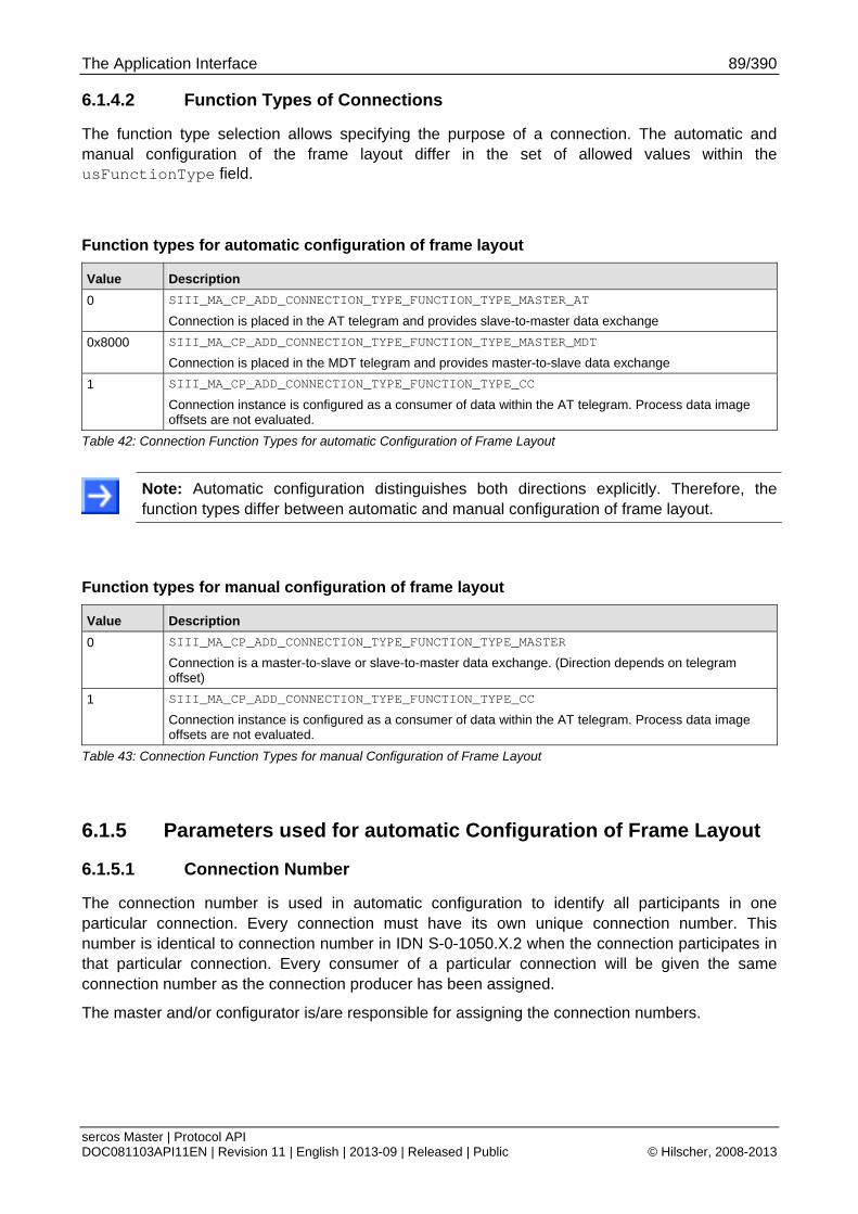
The Application Interface 89/390
sercos Master | Protocol API DOC081103API11EN | Revision 11 | English | 2013-09 | Released | Public © Hilscher, 2008-2013
6.1.4.2 Function Types of Connections
The function type selection allows specifying the purpose of a connection. The automatic and manual configuration of the frame layout differ in the set of allowed values within the usFunctionType field.
Function types for automatic configuration of frame layout
Value Description
0 SIII_MA_CP_ADD_CONNECTION_TYPE_FUNCTION_TYPE_MASTER_AT
Connection is placed in the AT telegram and provides slave-to-master data exchange
0x8000 SIII_MA_CP_ADD_CONNECTION_TYPE_FUNCTION_TYPE_MASTER_MDT
Connection is placed in the MDT telegram and provides master-to-slave data exchange
1 SIII_MA_CP_ADD_CONNECTION_TYPE_FUNCTION_TYPE_CC
Connection instance is configured as a consumer of data within the AT telegram. Process data image offsets are not evaluated.
Table 42: Connection Function Types for automatic Configuration of Frame Layout
Note: Automatic configuration distinguishes both directions explicitly. Therefore, the function types differ between automatic and manual configuration of frame layout.
Function types for manual configuration of frame layout
Value Description
0 SIII_MA_CP_ADD_CONNECTION_TYPE_FUNCTION_TYPE_MASTER
Connection is a master-to-slave or slave-to-master data exchange. (Direction depends on telegram offset)
1 SIII_MA_CP_ADD_CONNECTION_TYPE_FUNCTION_TYPE_CC
Connection instance is configured as a consumer of data within the AT telegram. Process data image offsets are not evaluated.
Table 43: Connection Function Types for manual Configuration of Frame Layout
6.1.5 Parameters used for automatic Configuration of Frame Layout
6.1.5.1 Connection Number
The connection number is used in automatic configuration to identify all participants in one particular connection. Every connection must have its own unique connection number. This number is identical to connection number in IDN S-0-1050.X.2 when the connection participates in that particular connection. Every consumer of a particular connection will be given the same connection number as the connection producer has been assigned.
The master and/or configurator is/are responsible for assigning the connection numbers.
The Application Interface 90/390
sercos Master | Protocol API DOC081103API11EN | Revision 11 | English | 2013-09 | Released | Public © Hilscher, 2008-2013
6.1.6 Common Services (all Packet Configuration Variants)
6.1.6.1 Begin a new Configuration Transfer Service
This service initiates a new configuration transfer. This request contains all parameters required by the master in order to prepare for transfer of any slave configuration (which is then performed with the subsequent packets)
Note: A new configuration transfer can only be started when the master is in NRT phase. During configuration transfer, any phase change is denied.
For detailed information on how to set the fields correctly, see one of the following chapters:
Automatic configuration of the frame layout with automatic timing calculation
See 6.1.7.1 Begin Configuration Transfer Parameters for automatic Configuration of Frame Layout with automatic
Automatic configuration of the frame layout with user specified timing parameters
See 6.1.8.1 Begin Configuration Transfer Parameters for automatic configuration of Frame Layout with user specified
Manual configuration of the frame layout and timing parameters
See 6.1.11.2 Begin Configuration Transfer Parameters for manual configuration of frame layout and timing parameters
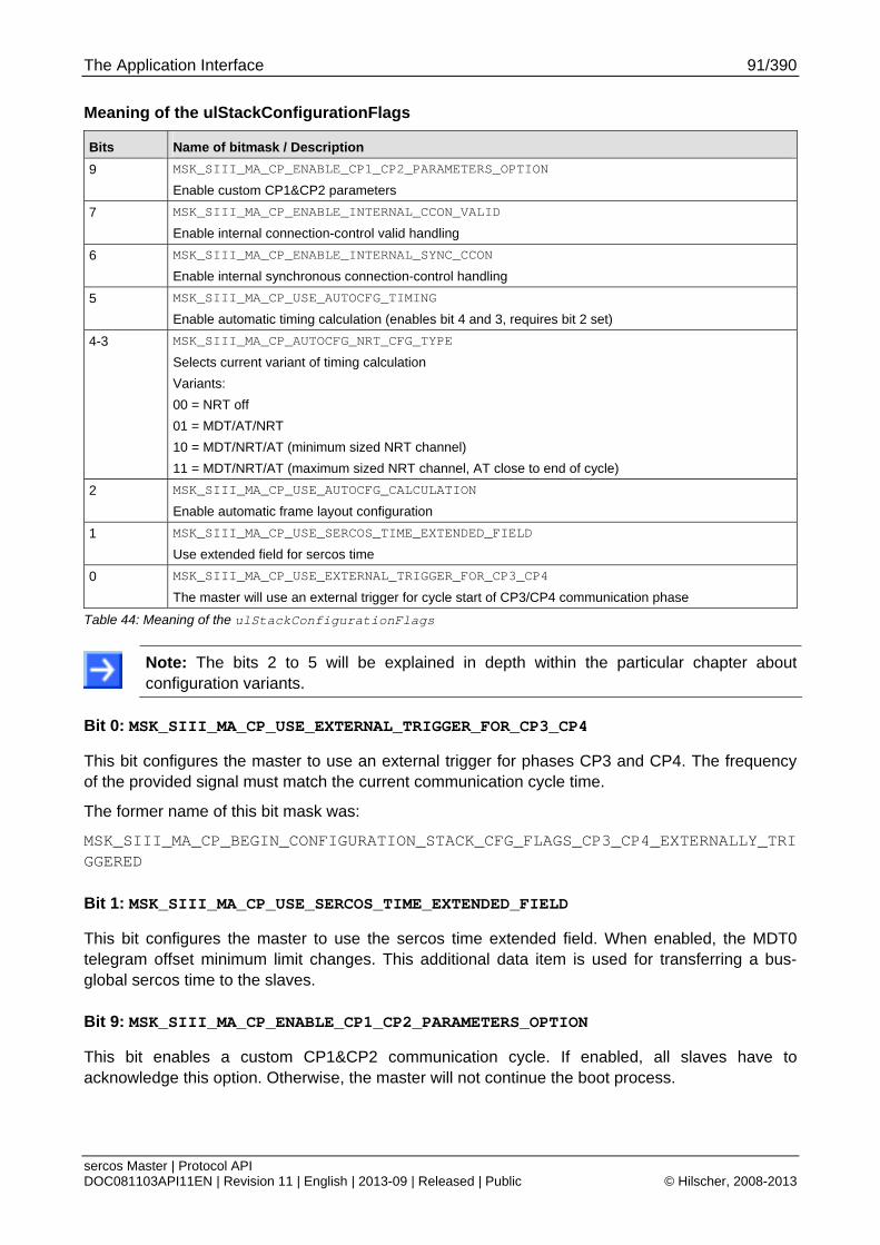
The Application Interface 91/390
sercos Master | Protocol API DOC081103API11EN | Revision 11 | English | 2013-09 | Released | Public © Hilscher, 2008-2013
Meaning of the ulStackConfigurationFlags
Bits Name of bitmask / Description
9 MSK_SIII_MA_CP_ENABLE_CP1_CP2_PARAMETERS_OPTION
Enable custom CP1&CP2 parameters
7 MSK_SIII_MA_CP_ENABLE_INTERNAL_CCON_VALID
Enable internal connection-control valid handling
6 MSK_SIII_MA_CP_ENABLE_INTERNAL_SYNC_CCON
Enable internal synchronous connection-control handling
5 MSK_SIII_MA_CP_USE_AUTOCFG_TIMING
Enable automatic timing calculation (enables bit 4 and 3, requires bit 2 set)
4-3 MSK_SIII_MA_CP_AUTOCFG_NRT_CFG_TYPE
Selects current variant of timing calculation
Variants:
00 = NRT off
01 = MDT/AT/NRT
10 = MDT/NRT/AT (minimum sized NRT channel)
11 = MDT/NRT/AT (maximum sized NRT channel, AT close to end of cycle)
2 MSK_SIII_MA_CP_USE_AUTOCFG_CALCULATION
Enable automatic frame layout configuration
1 MSK_SIII_MA_CP_USE_SERCOS_TIME_EXTENDED_FIELD
Use extended field for sercos time
0 MSK_SIII_MA_CP_USE_EXTERNAL_TRIGGER_FOR_CP3_CP4
The master will use an external trigger for cycle start of CP3/CP4 communication phase
Table 44: Meaning of the ulStackConfigurationFlags
Note: The bits 2 to 5 will be explained in depth within the particular chapter about configuration variants.
Bit 0: MSK_SIII_MA_CP_USE_EXTERNAL_TRIGGER_FOR_CP3_CP4
This bit configures the master to use an external trigger for phases CP3 and CP4. The frequency of the provided signal must match the current communication cycle time.
The former name of this bit mask was:
MSK_SIII_MA_CP_BEGIN_CONFIGURATION_STACK_CFG_FLAGS_CP3_CP4_EXTERNALLY_TRIGGERED
Bit 1: MSK_SIII_MA_CP_USE_SERCOS_TIME_EXTENDED_FIELD
This bit configures the master to use the sercos time extended field. When enabled, the MDT0 telegram offset minimum limit changes. This additional data item is used for transferring a bus-global sercos time to the slaves.
Bit 9: MSK_SIII_MA_CP_ENABLE_CP1_CP2_PARAMETERS_OPTION
This bit enables a custom CP1&CP2 communication cycle. If enabled, all slaves have to acknowledge this option. Otherwise, the master will not continue the boot process.

The Application Interface 92/390
sercos Master | Protocol API DOC081103API11EN | Revision 11 | English | 2013-09 | Released | Public © Hilscher, 2008-2013
Packet Structure Reference
typedef struct SIII_MA_CP_BEGIN_CONFIGURATION_REQ_DATA_Ttag { TLR_UINT32 ulCommunicationCycleTime; TLR_UINT32 ulCommunicationTimeoutCP3_4; TLR_UINT32 ulCommandValueValidTime; TLR_UINT32 ulATTransmissionStartingTime; TLR_UINT32 ulTransmissionTime_t6; TLR_UINT32 ulTransmissionTime_t7; TLR_UINT32 ulSynchronizationTime; TLR_UINT32 ulSyncJitter; TLR_UINT16 usNRTChannelMTU; TLR_UINT32 ulProcessDataOutputSize; TLR_UINT32 ulProcessDataInputSize; TLR_UINT32 ulCP0_CycleWait_For_StableState; TLR_UINT32 ulStackConfigurationFlags; TLR_UINT32 aulACFGReserved[8]; TLR_UINT32 ulMaximumTsRefCounter; TLR_UINT32 ulCP1_CP2_CommunicationCycleTime; TLR_UINT32 ulCP1_CP2_ATTransmissionStartingTime; TLR_UINT32 ulCP1_CP2_TransmissionTime_t6; TLR_UINT32 ulCP1_CP2_TransmissionTime_t7; TLR_UINT32 aulReserved[3]; } SIII_MA_CP_BEGIN_CONFIGURATION_REQ_DATA_T; typedef struct SIII_MA_CP_BEGIN_CONFIGURATION_REQ_Ttag { TLR_PACKET_HEADER_T tHead; SIII_MA_CP_BEGIN_CONFIGURATION_REQ_DATA_T tData; } SIII_MA_CP_BEGIN_CONFIGURATION_REQ_T;

The Application Interface 93/390
sercos Master | Protocol API DOC081103API11EN | Revision 11 | English | 2013-09 | Released | Public © Hilscher, 2008-2013
Packet Description
Structure SIII_MA_CP_BEGIN_CONFIGURATION_REQ_T Type: Request
Variable Type Value /
Range
Description
tHead - Structure TLR_PACKET_HEADER_T
ulDest UINT32 Destination Queue-Handle
ulSrc UINT32 Source Queue-Handle
ulDestId UINT32 Destination End Point Identifier, specifying the final receiver of the packet within the Destination Process. Set to 0 for the Initialization Packet
ulSrcId UINT32 Source End Point Identifier, specifying the origin of the packet inside the Source Process
ulLen UINT32 114 Packet Data Length in bytes
ulId UINT32 0 ... 232-1 Packet Identification as unique number generated by the Source Process of the Packet
ulSta UINT32 See section Status/Error Codes Overview
ulCmd UINT32 0x4820 SIII_MA_CP_CMD_BEGIN_CONFIGURATION_REQ - Command
ulExt UINT32 0 Extension, reserved
ulRout UINT32 x Routing, do not touch
tData - Structure SIII_MA_CP_BEGIN_CONFIGURATION_REQ_DATA_T
ulCommunicationCycleTime UINT32 31 250 … 65 000 000
Communication Cycle Time (CP3/4)
For a list of the allowed values see section 4.2.3.1. Do not choose values lower than the minimum cycle time of 250 µs, see section 1.5.1 “Technical Data”.
ulCommunicationTimeoutCP3_4
UINT32 range depends on slave
Communication Timeout (CP3/4)
ulCommandValueValidTime UINT32 0…tScyc Command Value Valid time (t3)
ulATTransmissionStartingTime
UINT32 0…tScyc AT Transmission Starting Time
ulTransmissionTime_t6 UINT32 0…tScyc NRT Transmission Time (t6)
ulTransmissionTime_t7 UINT32 0…tScyc NRT Transmission Time (t7)
ulSynchronizationTime UINT32 0…tScyc Feedback Acquisition Capture Point (Synchronization time) (t4)
ulSyncJitter UINT32 Maximum Value
tScyc / 2
Sync Jitter
internally calculated since V2.1.X
usNRTChannelMTU UINT16 46…1500
depends on Communication Phase
NRT Channel MTU
ulProcessDataOutputSize UINT32 0 … 5760
(Only even values!)
Process Data Output Size (MDT)
Important: Do not specify odd values for the Process Data
Output Size!
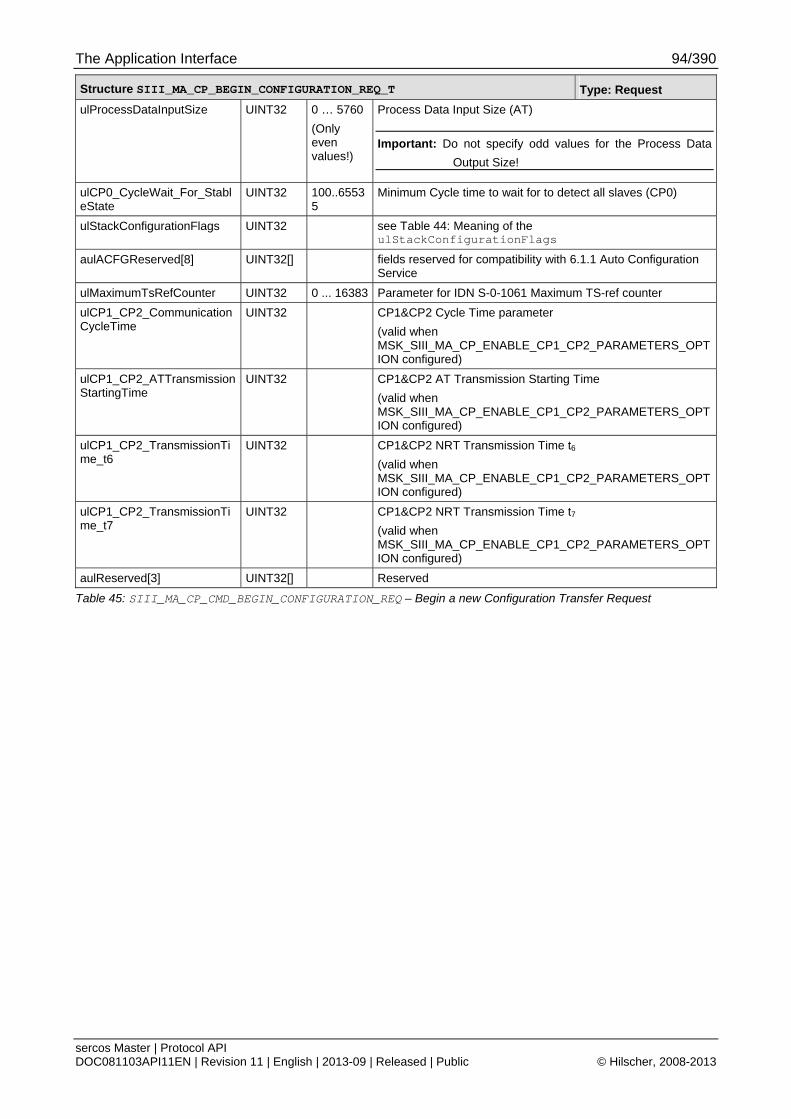
The Application Interface 94/390
sercos Master | Protocol API DOC081103API11EN | Revision 11 | English | 2013-09 | Released | Public © Hilscher, 2008-2013
Structure SIII_MA_CP_BEGIN_CONFIGURATION_REQ_T Type: Request
ulProcessDataInputSize UINT32 0 … 5760
(Only even values!)
Process Data Input Size (AT)
Important: Do not specify odd values for the Process Data
Output Size!
ulCP0_CycleWait_For_StableState
UINT32 100..65535
Minimum Cycle time to wait for to detect all slaves (CP0)
ulStackConfigurationFlags UINT32 see Table 44: Meaning of the ulStackConfigurationFlags
aulACFGReserved[8] UINT32[] fields reserved for compatibility with 6.1.1 Auto Configuration Service
ulMaximumTsRefCounter UINT32 0 ... 16383 Parameter for IDN S-0-1061 Maximum TS-ref counter
ulCP1_CP2_CommunicationCycleTime
UINT32 CP1&CP2 Cycle Time parameter
(valid when MSK_SIII_MA_CP_ENABLE_CP1_CP2_PARAMETERS_OPTION configured)
ulCP1_CP2_ATTransmissionStartingTime
UINT32 CP1&CP2 AT Transmission Starting Time
(valid when MSK_SIII_MA_CP_ENABLE_CP1_CP2_PARAMETERS_OPTION configured)
ulCP1_CP2_TransmissionTime_t6
UINT32 CP1&CP2 NRT Transmission Time t6
(valid when MSK_SIII_MA_CP_ENABLE_CP1_CP2_PARAMETERS_OPTION configured)
ulCP1_CP2_TransmissionTime_t7
UINT32 CP1&CP2 NRT Transmission Time t7
(valid when MSK_SIII_MA_CP_ENABLE_CP1_CP2_PARAMETERS_OPTION configured)
aulReserved[3] UINT32[] Reserved
Table 45: SIII_MA_CP_CMD_BEGIN_CONFIGURATION_REQ – Begin a new Configuration Transfer Request

The Application Interface 95/390
sercos Master | Protocol API DOC081103API11EN | Revision 11 | English | 2013-09 | Released | Public © Hilscher, 2008-2013
Packet Structure Reference
typedef struct SIII_MA_CP_BEGIN_CONFIGURATION_CNF_Ttag { TLR_PACKET_HEADER_T tHead; } SIII_MA_CP_BEGIN_CONFIGURATION_CNF_T;
Packet Description
Structure SIII_MA_CP_BEGIN_CONFIGURATION_CNF_T Type: Confirmation
Variable Type Value / Range Description
tHead - Structure TLR_PACKET_HEADER_T
ulDest UINT32 Destination queue handle, unchanged
ulSrc UINT32 Source queue handle, unchanged
ulDestId UINT32 Destination End Point Identifier, specifying the final receiver of the packet within the Destination Process. Set to 0 for the Initialization Packet
ulSrcId UINT32 Source End Point Identifier, specifying the origin of the packet inside the Source Process
ulLen UINT32 0 Packet Data Length in bytes
ulId UINT32 0 ... 232-1 Packet Identification as unique number generated by the Source Process of the Packet
ulSta UINT32 See section Status/Error Codes Overview
ulCmd UINT32 0x4821 SIII_MA_CP_CMD_BEGIN_CONFIGURATION_CNF - Command
ulExt UINT32 0 Extension not in use, set to zero for compatibility reasons
ulRout UINT32 x Routing, do not touch
Table 46: SIII_MA_CP_CMD_BEGIN_CONFIGURATION_CNF – Begin a new Configuration Transfer Confirmation
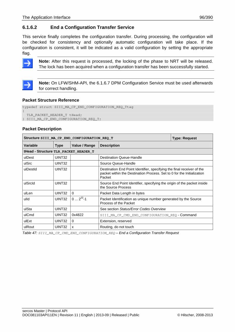
The Application Interface 96/390
sercos Master | Protocol API DOC081103API11EN | Revision 11 | English | 2013-09 | Released | Public © Hilscher, 2008-2013
6.1.6.2 End a Configuration Transfer Service
This service finally completes the configuration transfer. During processing, the configuration will be checked for consistency and optionally automatic configuration will take place. If the configuration is consistent, it will be indicated as a valid configuration by setting the appropriate flag.
Note: After this request is processed, the locking of the phase to NRT will be released. The lock has been acquired when a configuration transfer has been successfully started.
Note: On LFW/SHM-API, the 6.1.6.7 DPM Configuration Service must be used afterwards for correct handling.
Packet Structure Reference
typedef struct SIII_MA_CP_END_CONFIGURATION_REQ_Ttag { TLR_PACKET_HEADER_T tHead; } SIII_MA_CP_END_CONFIGURATION_REQ_T;
Packet Description
Structure SIII_MA_CP_END_CONFIGURATION_REQ_T Type: Request
Variable Type Value / Range Description
tHead - Structure TLR_PACKET_HEADER_T
ulDest UINT32 Destination Queue-Handle
ulSrc UINT32 Source Queue-Handle
ulDestId UINT32 Destination End Point Identifier, specifying the final receiver of the packet within the Destination Process. Set to 0 for the Initialization Packet
ulSrcId UINT32 Source End Point Identifier, specifying the origin of the packet inside the Source Process
ulLen UINT32 0 Packet Data Length in bytes
ulId UINT32 0 ... 232-1 Packet Identification as unique number generated by the Source Process of the Packet
ulSta UINT32 See section Status/Error Codes Overview
ulCmd UINT32 0x4822 SIII_MA_CP_CMD_END_CONFIGURATION_REQ - Command
ulExt UINT32 0 Extension, reserved
ulRout UINT32 x Routing, do not touch
Table 47: SIII_MA_CP_CMD_END_CONFIGURATION_REQ – End a Configuration Transfer Request
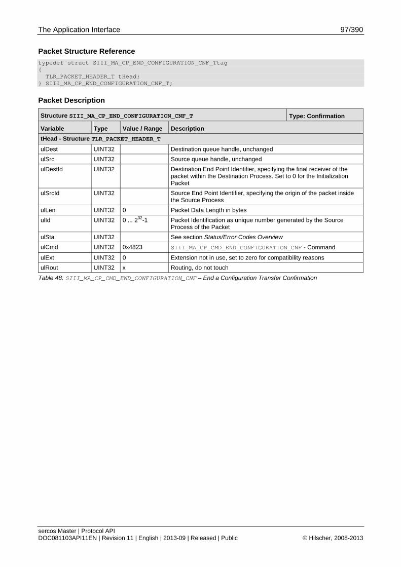
The Application Interface 97/390
sercos Master | Protocol API DOC081103API11EN | Revision 11 | English | 2013-09 | Released | Public © Hilscher, 2008-2013
Packet Structure Reference
typedef struct SIII_MA_CP_END_CONFIGURATION_CNF_Ttag { TLR_PACKET_HEADER_T tHead; } SIII_MA_CP_END_CONFIGURATION_CNF_T;
Packet Description
Structure SIII_MA_CP_END_CONFIGURATION_CNF_T Type: Confirmation
Variable Type Value / Range Description
tHead - Structure TLR_PACKET_HEADER_T
ulDest UINT32 Destination queue handle, unchanged
ulSrc UINT32 Source queue handle, unchanged
ulDestId UINT32 Destination End Point Identifier, specifying the final receiver of the packet within the Destination Process. Set to 0 for the Initialization Packet
ulSrcId UINT32 Source End Point Identifier, specifying the origin of the packet inside the Source Process
ulLen UINT32 0 Packet Data Length in bytes
ulId UINT32 0 ... 232-1 Packet Identification as unique number generated by the Source Process of the Packet
ulSta UINT32 See section Status/Error Codes Overview
ulCmd UINT32 0x4823 SIII_MA_CP_CMD_END_CONFIGURATION_CNF - Command
ulExt UINT32 0 Extension not in use, set to zero for compatibility reasons
ulRout UINT32 x Routing, do not touch
Table 48: SIII_MA_CP_CMD_END_CONFIGURATION_CNF – End a Configuration Transfer Confirmation
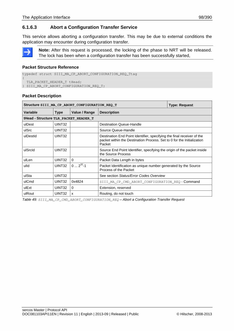
The Application Interface 98/390
sercos Master | Protocol API DOC081103API11EN | Revision 11 | English | 2013-09 | Released | Public © Hilscher, 2008-2013
6.1.6.3 Abort a Configuration Transfer Service
This service allows aborting a configuration transfer. This may be due to external conditions the application may encounter during configuration transfer.
Note: After this request is processed, the locking of the phase to NRT will be released. The lock has been when a configuration transfer has been successfully started,
Packet Structure Reference
typedef struct SIII_MA_CP_ABORT_CONFIGURATION_REQ_Ttag { TLR_PACKET_HEADER_T tHead; } SIII_MA_CP_ABORT_CONFIGURATION_REQ_T;
Packet Description
Structure SIII_MA_CP_ABORT_CONFIGURATION_REQ_T Type: Request
Variable Type Value / Range Description
tHead - Structure TLR_PACKET_HEADER_T
ulDest UINT32 Destination Queue-Handle
ulSrc UINT32 Source Queue-Handle
ulDestId UINT32 Destination End Point Identifier, specifying the final receiver of the packet within the Destination Process. Set to 0 for the Initialization Packet
ulSrcId UINT32 Source End Point Identifier, specifying the origin of the packet inside the Source Process
ulLen UINT32 0 Packet Data Length in bytes
ulId UINT32 0 ... 232-1 Packet Identification as unique number generated by the Source Process of the Packet
ulSta UINT32 See section Status/Error Codes Overview
ulCmd UINT32 0x4824 SIII_MA_CP_CMD_ABORT_CONFIGURATION_REQ - Command
ulExt UINT32 0 Extension, reserved
ulRout UINT32 x Routing, do not touch
Table 49: SIII_MA_CP_CMD_ABORT_CONFIGURATION_REQ – Abort a Configuration Transfer Request

The Application Interface 99/390
sercos Master | Protocol API DOC081103API11EN | Revision 11 | English | 2013-09 | Released | Public © Hilscher, 2008-2013
Packet Structure Reference
typedef struct SIII_MA_CP_ABORT_CONFIGURATION_CNF_Ttag { TLR_PACKET_HEADER_T tHead; } SIII_MA_CP_ABORT_CONFIGURATION_CNF_T;
Packet Description
Structure SIII_MA_CP_ABORT_CONFIGURATION_CNF_T Type: Confirmation
Variable Type Value / Range Description
tHead - Structure TLR_PACKET_HEADER_T
ulDest UINT32 Destination queue handle, unchanged
ulSrc UINT32 Source queue handle, unchanged
ulDestId UINT32 Destination End Point Identifier, specifying the final receiver of the packet within the Destination Process. Set to 0 for the Initialization Packet
ulSrcId UINT32 Source End Point Identifier, specifying the origin of the packet inside the Source Process
ulLen UINT32 0 Packet Data Length in bytes
ulId UINT32 0 ... 232-1 Packet Identification as unique number generated by the Source Process of the Packet
ulSta UINT32 See section Status/Error Codes Overview
ulCmd UINT32 0x4825 SIII_MA_CP_CMD_ABORT_CONFIGURATION_CNF - Command
ulExt UINT32 0 Extension not in use, set to zero for compatibility reasons
ulRout UINT32 x Routing, do not touch
Table 50: SIII_MA_CP_CMD_ABORT_CONFIGURATION_CNF – Abort a Configuration Transfer Confirmation

The Application Interface 100/390
sercos Master | Protocol API DOC081103API11EN | Revision 11 | English | 2013-09 | Released | Public © Hilscher, 2008-2013
6.1.6.4 Add Slave Ident Data Service
This packet allows adding the slave identification to the configuration block
Note: Without using this service, the service 6.2.3 Get Configured Slave Identification Data Service (since version V2.1.X) will not be able to provide the identification data.
Field abDeviceID
The field abDeviceID contains the device id of the device. Its length is specified by ulLen - SIII_MA_CP_ADD_SLAVE_IDENT_REQ_MIN_SIZE. The range of the abDeviceID length is between 1 and 255.
Packet Structure Reference
typedef struct SIII_MA_CP_ADD_SLAVE_IDENT_REQ_DATA_Ttag { TLR_UINT16 usSlaveAddress; TLR_UINT16 usConfigFlags; TLR_UINT16 usVendorCode; TLR_UINT8 abDeviceID[255]; } SIII_MA_CP_ADD_SLAVE_IDENT_REQ_DATA_T; typedef struct SIII_MA_CP_ADD_SLAVE_IDENT_REQ_Ttag { TLR_PACKET_HEADER_T tHead; SIII_MA_CP_ADD_SLAVE_IDENT_REQ_DATA_T tData; } SIII_MA_CP_ADD_SLAVE_IDENT_REQ_T;
Packet Description
Structure SIII_MA_CP_ADD_SLAVE_IDENT_REQ_T Type: Request
Variable Type Value / Range Description
tHead - Structure TLR_PACKET_HEADER_T
ulDest UINT32 Destination Queue-Handle
ulSrc UINT32 Source Queue-Handle
ulDestId UINT32 Destination End Point Identifier, specifying the final receiver of the packet within the Destination Process. Set to 0 for the Initialization Packet
ulSrcId UINT32 Source End Point Identifier, specifying the origin of the packet inside the Source Process
ulLen UINT32 6 + length of device id (n)
Packet Data Length in bytes
ulId UINT32 0 ... 232-1 Packet Identification as unique number generated by the Source Process of the Packet
ulSta UINT32 See section Status/Error Codes Overview
ulCmd UINT32 0x8910 SIII_MA_CP_CMD_ADD_SLAVE_IDENT_REQ - Command
ulExt UINT32 0 Extension, reserved
ulRout UINT32 x Routing, do not touch
tData - Structure SIII_MA_CP_ADD_SLAVE_IDENT_REQ_DATA_T
usSlaveAddress UINT16 1.. 511 Slave Address
usConfigFlags UINT16 0 reserved, set to zero
usVendorCode UINT16 Vendor code of slave
abDeviceID UINT8[n]
Device ID of slave
Table 51: SIII_MA_CP_CMD_ADD_SLAVE_IDENT_REQ – Add Slave Ident Request

The Application Interface 101/390
sercos Master | Protocol API DOC081103API11EN | Revision 11 | English | 2013-09 | Released | Public © Hilscher, 2008-2013
Packet Structure Reference
typedef struct SIII_MA_CP_ADD_SLAVE_IDENT_CNF_Ttag { TLR_PACKET_HEADER_T tHead; } SIII_MA_CP_ADD_SLAVE_IDENT_CNF_T;
Packet Description
Structure SIII_MA_CP_ADD_SLAVE_IDENT_CNF_T Type: Confirmation
Variable Type Value / Range Description
tHead - Structure TLR_PACKET_HEADER_T
ulDest UINT32 Destination queue handle, unchanged
ulSrc UINT32 Source queue handle, unchanged
ulDestId UINT32 Destination End Point Identifier, specifying the final receiver of the packet within the Destination Process. Set to 0 for the Initialization Packet
ulSrcId UINT32 Source End Point Identifier, specifying the origin of the packet inside the Source Process
ulLen UINT32 0 Packet Data Length in bytes
ulId UINT32 0 ... 232-1 Packet Identification as unique number generated by the Source Process of the Packet
ulSta UINT32 See section Status/Error Codes Overview
ulCmd UINT32 0x8911 SIII_MA_CP_CMD_ADD_SLAVE_IDENT_CNF - Command
ulExt UINT32 0 Extension not in use, set to zero for compatibility reasons
ulRout UINT32 x Routing, do not touch
Table 52: SIII_MA_CP_CMD_ADD_SLAVE_IDENT_CNF – Add Slave Ident Confirmation
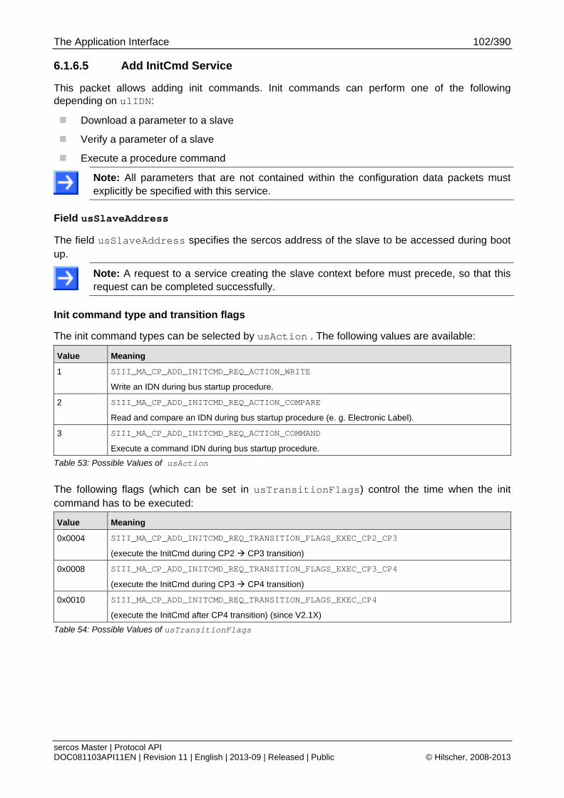
The Application Interface 102/390
sercos Master | Protocol API DOC081103API11EN | Revision 11 | English | 2013-09 | Released | Public © Hilscher, 2008-2013
6.1.6.5 Add InitCmd Service
This packet allows adding init commands. Init commands can perform one of the following depending on ulIDN:
Download a parameter to a slave
Verify a parameter of a slave
Execute a procedure command
Note: All parameters that are not contained within the configuration data packets must explicitly be specified with this service.
Field usSlaveAddress
The field usSlaveAddress specifies the sercos address of the slave to be accessed during boot up.
Note: A request to a service creating the slave context before must precede, so that this request can be completed successfully.
Init command type and transition flags
The init command types can be selected by usAction . The following values are available:
Value Meaning
1 SIII_MA_CP_ADD_INITCMD_REQ_ACTION_WRITE
Write an IDN during bus startup procedure.
2 SIII_MA_CP_ADD_INITCMD_REQ_ACTION_COMPARE
Read and compare an IDN during bus startup procedure (e. g. Electronic Label).
3 SIII_MA_CP_ADD_INITCMD_REQ_ACTION_COMMAND
Execute a command IDN during bus startup procedure.
Table 53: Possible Values of usAction
The following flags (which can be set in usTransitionFlags) control the time when the init command has to be executed:
Value Meaning
0x0004 SIII_MA_CP_ADD_INITCMD_REQ_TRANSITION_FLAGS_EXEC_CP2_CP3
(execute the InitCmd during CP2 CP3 transition)
0x0008 SIII_MA_CP_ADD_INITCMD_REQ_TRANSITION_FLAGS_EXEC_CP3_CP4
(execute the InitCmd during CP3 CP4 transition)
0x0010 SIII_MA_CP_ADD_INITCMD_REQ_TRANSITION_FLAGS_EXEC_CP4
(execute the InitCmd after CP4 transition) (since V2.1X)
Table 54: Possible Values of usTransitionFlags
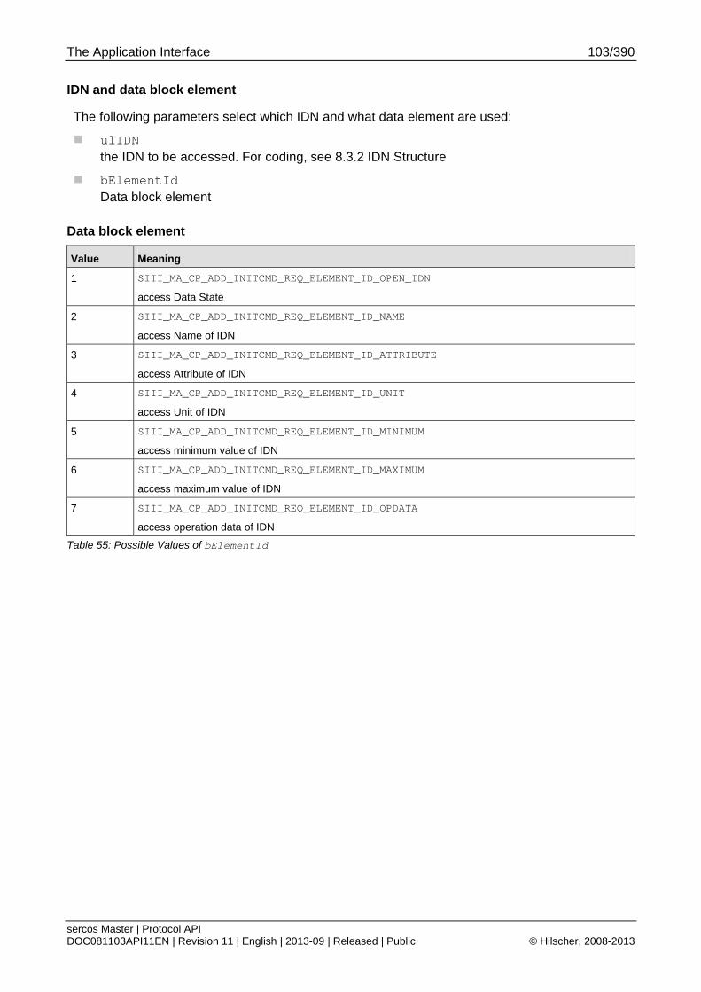
The Application Interface 103/390
sercos Master | Protocol API DOC081103API11EN | Revision 11 | English | 2013-09 | Released | Public © Hilscher, 2008-2013
IDN and data block element
The following parameters select which IDN and what data element are used:
ulIDN the IDN to be accessed. For coding, see 8.3.2 IDN Structure
bElementId Data block element
Data block element
Value Meaning
1 SIII_MA_CP_ADD_INITCMD_REQ_ELEMENT_ID_OPEN_IDN
access Data State
2 SIII_MA_CP_ADD_INITCMD_REQ_ELEMENT_ID_NAME
access Name of IDN
3 SIII_MA_CP_ADD_INITCMD_REQ_ELEMENT_ID_ATTRIBUTE
access Attribute of IDN
4 SIII_MA_CP_ADD_INITCMD_REQ_ELEMENT_ID_UNIT
access Unit of IDN
5 SIII_MA_CP_ADD_INITCMD_REQ_ELEMENT_ID_MINIMUM
access minimum value of IDN
6 SIII_MA_CP_ADD_INITCMD_REQ_ELEMENT_ID_MAXIMUM
access maximum value of IDN
7 SIII_MA_CP_ADD_INITCMD_REQ_ELEMENT_ID_OPDATA
access operation data of IDN
Table 55: Possible Values of bElementId
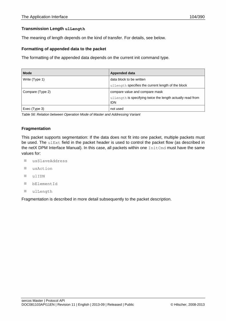
The Application Interface 104/390
sercos Master | Protocol API DOC081103API11EN | Revision 11 | English | 2013-09 | Released | Public © Hilscher, 2008-2013
Transmission Length ulLength
The meaning of length depends on the kind of transfer. For details, see below.
Formatting of appended data to the packet
The formatting of the appended data depends on the current init command type.
Mode Appended data
Write (Type 1) data block to be written
ulLength specifies the current length of the block
Compare (Type 2) compare value and compare mask
ulLength is specifying twice the length actually read from IDN
Exec (Type 3) not used
Table 56: Relation between Operation Mode of Master and Addressing Variant
Fragmentation
This packet supports segmentation: If the data does not fit into one packet, multiple packets must be used. The ulExt field in the packet header is used to control the packet flow (as described in the netX DPM Interface Manual). In this case, all packets within one InitCmd must have the same values for:
usSlaveAddress
usAction
ulIDN
bElementId
ulLength
Fragmentation is described in more detail subsequently to the packet description.
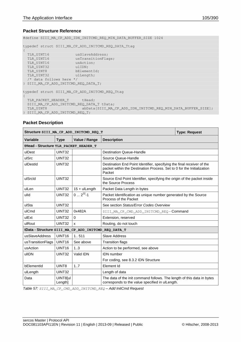
The Application Interface 105/390
sercos Master | Protocol API DOC081103API11EN | Revision 11 | English | 2013-09 | Released | Public © Hilscher, 2008-2013
Packet Structure Reference
#define SIII_MA_CP_ADD_IDN_INITCMD_REQ_MIN_DATA_BUFFER_SIZE 1024 typedef struct SIII_MA_CP_ADD_INITCMD_REQ_DATA_Ttag { TLR_UINT16 usSlaveAddress; TLR_UINT16 usTransitionFlags; TLR_UINT16 usAction; TLR_UINT32 ulIDN; TLR_UINT8 bElementId; TLR_UINT32 ulLength; /* data follows here */ } SIII_MA_CP_ADD_INITCMD_REQ_DATA_T; typedef struct SIII_MA_CP_ADD_INITCMD_REQ_Ttag { TLR_PACKET_HEADER_T tHead; SIII_MA_CP_ADD_INITCMD_REQ_DATA_T tData; TLR_UINT8 abData[SIII_MA_CP_ADD_IDN_INITCMD_REQ_MIN_DATA_BUFFER_SIZE]; } SIII_MA_CP_ADD_INITCMD_REQ_T;
Packet Description
Structure SIII_MA_CP_ADD_INITCMD_REQ_T Type: Request
Variable Type Value / Range Description
tHead - Structure TLR_PACKET_HEADER_T
ulDest UINT32 Destination Queue-Handle
ulSrc UINT32 Source Queue-Handle
ulDestId UINT32 Destination End Point Identifier, specifying the final receiver of the packet within the Destination Process. Set to 0 for the Initialization Packet
ulSrcId UINT32 Source End Point Identifier, specifying the origin of the packet inside the Source Process
ulLen UINT32 15 + ulLength Packet Data Length in bytes
ulId UINT32 0 ... 232-1 Packet Identification as unique number generated by the Source Process of the Packet
ulSta UINT32 See section Status/Error Codes Overview
ulCmd UINT32 0x482A SIII_MA_CP_CMD_ADD_INITCMD_REQ - Command
ulExt UINT32 0 Extension, reserved
ulRout UINT32 x Routing, do not touch
tData - Structure SIII_MA_CP_ADD_INITCMD_REQ_DATA_T
usSlaveAddress UINT16 1.. 511 Slave Address
usTransitionFlags UINT16 See above Transition flags
usAction UINT16 1..3 Action to be performed, see above
ulIDN UINT32 Valid IDN IDN number
For coding, see 8.3.2 IDN Structure
bElementId UINT8 1..7 Element Id
ulLength UINT32 Length of data
Data UINT8[ulLength]
The data of the init command follows. The length of this data in bytes corresponds to the value specified in ulLength.
Table 57: SIII_MA_CP_CMD_ADD_INITCMD_REQ – Add InitCmd Request
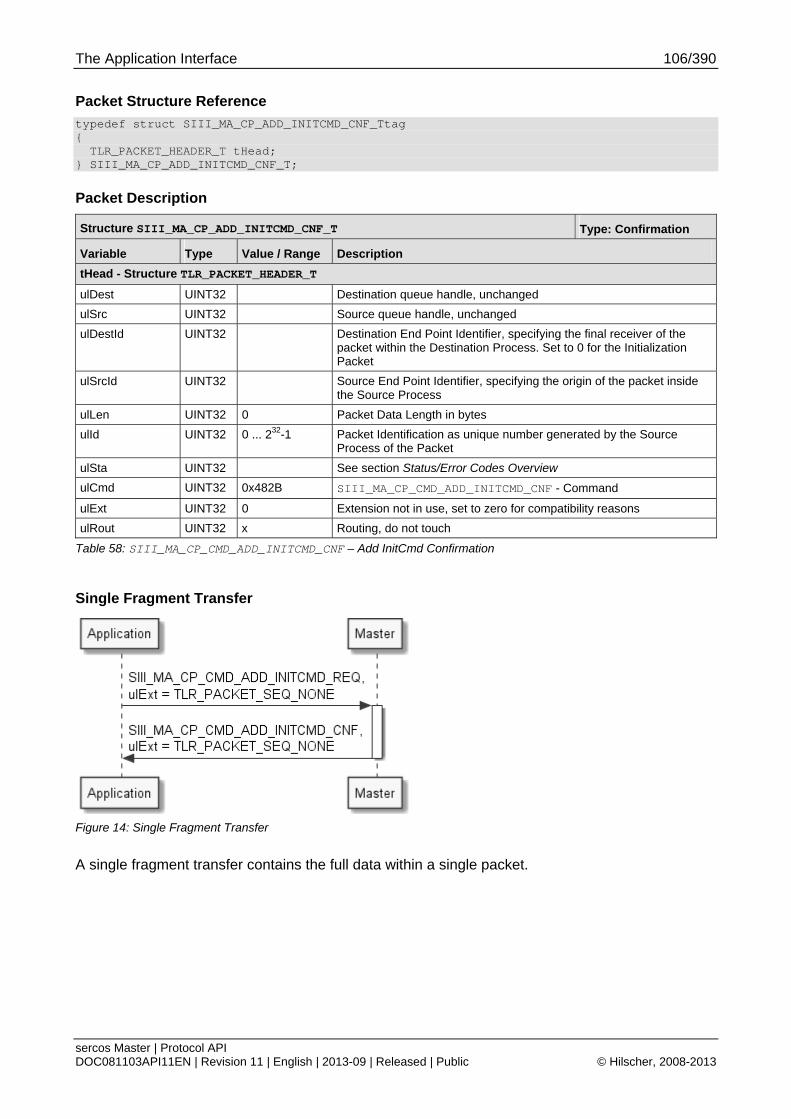
The Application Interface 106/390
sercos Master | Protocol API DOC081103API11EN | Revision 11 | English | 2013-09 | Released | Public © Hilscher, 2008-2013
Packet Structure Reference
typedef struct SIII_MA_CP_ADD_INITCMD_CNF_Ttag { TLR_PACKET_HEADER_T tHead; } SIII_MA_CP_ADD_INITCMD_CNF_T;
Packet Description
Structure SIII_MA_CP_ADD_INITCMD_CNF_T Type: Confirmation
Variable Type Value / Range Description
tHead - Structure TLR_PACKET_HEADER_T
ulDest UINT32 Destination queue handle, unchanged
ulSrc UINT32 Source queue handle, unchanged
ulDestId UINT32 Destination End Point Identifier, specifying the final receiver of the packet within the Destination Process. Set to 0 for the Initialization Packet
ulSrcId UINT32 Source End Point Identifier, specifying the origin of the packet inside the Source Process
ulLen UINT32 0 Packet Data Length in bytes
ulId UINT32 0 ... 232-1 Packet Identification as unique number generated by the Source Process of the Packet
ulSta UINT32 See section Status/Error Codes Overview
ulCmd UINT32 0x482B SIII_MA_CP_CMD_ADD_INITCMD_CNF - Command
ulExt UINT32 0 Extension not in use, set to zero for compatibility reasons
ulRout UINT32 x Routing, do not touch
Table 58: SIII_MA_CP_CMD_ADD_INITCMD_CNF – Add InitCmd Confirmation
Single Fragment Transfer
Figure 14: Single Fragment Transfer
A single fragment transfer contains the full data within a single packet.
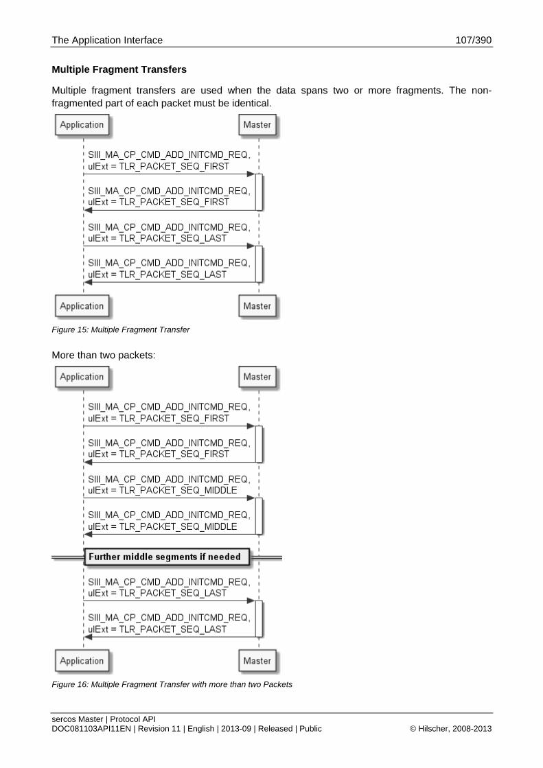
The Application Interface 107/390
sercos Master | Protocol API DOC081103API11EN | Revision 11 | English | 2013-09 | Released | Public © Hilscher, 2008-2013
Multiple Fragment Transfers
Multiple fragment transfers are used when the data spans two or more fragments. The non-fragmented part of each packet must be identical.
Figure 15: Multiple Fragment Transfer
More than two packets:
Figure 16: Multiple Fragment Transfer with more than two Packets
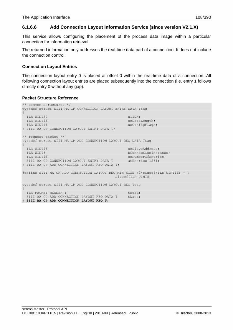
The Application Interface 108/390
sercos Master | Protocol API DOC081103API11EN | Revision 11 | English | 2013-09 | Released | Public © Hilscher, 2008-2013
6.1.6.6 Add Connection Layout Information Service (since version V2.1.X)
This service allows configuring the placement of the process data image within a particular connection for information retrieval.
The returned information only addresses the real-time data part of a connection. It does not include the connection control.
Connection Layout Entries
The connection layout entry 0 is placed at offset 0 within the real-time data of a connection. All following connection layout entries are placed subsequently into the connection (i.e. entry 1 follows directly entry 0 without any gap).
Packet Structure Reference
/* common structures */ typedef struct SIII_MA_CP_CONNECTION_LAYOUT_ENTRY_DATA_Ttag { TLR_UINT32 ulIDN; TLR_UINT16 usDataLength; TLR_UINT16 usConfigFlags; } SIII_MA_CP_CONNECTION_LAYOUT_ENTRY_DATA_T; /* request packet */ typedef struct SIII_MA_CP_ADD_CONNECTION_LAYOUT_REQ_DATA_Ttag { TLR_UINT16 usSlaveAddress; TLR_UINT8 bConnectionInstance; TLR_UINT16 usNumberOfEntries; SIII_MA_CP_CONNECTION_LAYOUT_ENTRY_DATA_T atEntries[128]; } SIII_MA_CP_ADD_CONNECTION_LAYOUT_REQ_DATA_T; #define SIII_MA_CP_ADD_CONNECTION_LAYOUT_REQ_MIN_SIZE (2*sizeof(TLR_UINT16) + \ sizeof(TLR_UINT8)) typedef struct SIII_MA_CP_ADD_CONNECTION_LAYOUT_REQ_Ttag { TLR_PACKET_HEADER_T tHead; SIII_MA_CP_ADD_CONNECTION_LAYOUT_REQ_DATA_T tData; } SIII_MA_CP_ADD_CONNECTION_LAYOUT_REQ_T;
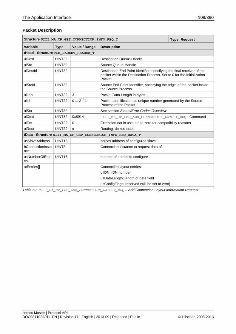
The Application Interface 109/390
sercos Master | Protocol API DOC081103API11EN | Revision 11 | English | 2013-09 | Released | Public © Hilscher, 2008-2013
Packet Description
Structure SIII_MA_CP_GET_CONNECTION_INFO_REQ_T Type: Request
Variable Type Value / Range Description
tHead - Structure TLR_PACKET_HEADER_T
ulDest UINT32 Destination Queue-Handle
ulSrc UINT32 Source Queue-Handle
ulDestId UINT32 Destination End Point Identifier, specifying the final receiver of the packet within the Destination Process. Set to 0 for the Initialization Packet
ulSrcId UINT32 Source End Point Identifier, specifying the origin of the packet inside the Source Process
ulLen UINT32 3 Packet Data Length in bytes
ulId UINT32 0 ... 232-1 Packet Identification as unique number generated by the Source Process of the Packet
ulSta UINT32 See section Status/Error Codes Overview
ulCmd UINT32 0x8914 SIII_MA_CP_CMD_ADD_CONNECTION_LAYOUT_REQ - Command
ulExt UINT32 0 Extension not in use, set to zero for compatibility reasons
ulRout UINT32 x Routing, do not touch
tData - Structure SIII_MA_CP_GET_CONNECTION_INFO_REQ_DATA_T
usSlaveAddress UINT16 sercos address of configured slave
bConnectionInstance
UINT8 Connection instance to request data of
usNumberOfEntries
UINT16 number of entries to configure
atEntries[] Connection layout entries:
ulIDN: IDN number
usDataLength: length of data field
usConfigFlags: reserved (will be set to zero)
Table 59: SIII_MA_CP_CMD_ADD_CONNECTION_LAYOUT_REQ – Add Connection Layout Information Request

The Application Interface 110/390
sercos Master | Protocol API DOC081103API11EN | Revision 11 | English | 2013-09 | Released | Public © Hilscher, 2008-2013
Packet Structure Reference
typedef struct SIII_MA_CP_ADD_CONNECTION_LAYOUT_CNF_Ttag { TLR_PACKET_HEADER_T tHead; } SIII_MA_CP_ADD_CONNECTION_LAYOUT_CNF_T;
Packet Description
Structure SIII_MA_CP_ADD_CONNECTION_LAYOUT_CNF_T Type: Confirmation
Variable Type Value / Range Description
tHead - Structure TLR_PACKET_HEADER_T
ulDest UINT32 Destination Queue-Handle
ulSrc UINT32 Source Queue-Handle
ulDestId UINT32 Destination End Point Identifier, specifying the final receiver of the packet within the Destination Process. Set to 0 for the Initialization Packet
ulSrcId UINT32 Source End Point Identifier, specifying the origin of the packet inside the Source Process
ulLen UINT32 0 Packet Data Length in bytes
ulId UINT32 0 ... 232-1 Packet Identification as unique number generated by the Source Process of the Packet
ulSta UINT32 See section Status/Error Codes Overview
ulCmd UINT32 0x8915 SIII_MA_CP_CMD_ADD_CONNECTION_LAYOUT_CNF - Command
ulExt UINT32 0 Extension not in use, set to zero for compatibility reasons
ulRout UINT32 x Routing, do not touch
Table 60: SIII_MA_CP_CMD_ADD_CONNECTION_LAYOUT_CNF –Add Connection Layout Information Confirmation
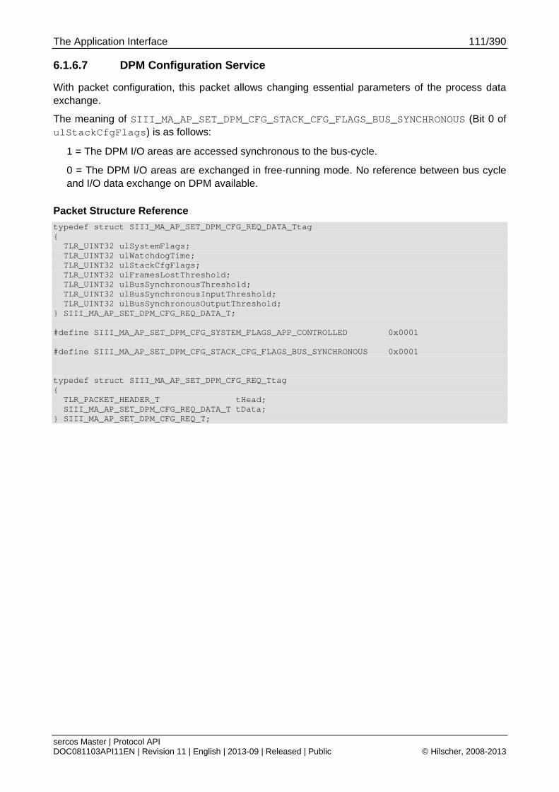
The Application Interface 111/390
sercos Master | Protocol API DOC081103API11EN | Revision 11 | English | 2013-09 | Released | Public © Hilscher, 2008-2013
6.1.6.7 DPM Configuration Service
With packet configuration, this packet allows changing essential parameters of the process data exchange.
The meaning of SIII_MA_AP_SET_DPM_CFG_STACK_CFG_FLAGS_BUS_SYNCHRONOUS (Bit 0 of ulStackCfgFlags) is as follows:
1 = The DPM I/O areas are accessed synchronous to the bus-cycle.
0 = The DPM I/O areas are exchanged in free-running mode. No reference between bus cycle and I/O data exchange on DPM available.
Packet Structure Reference
typedef struct SIII_MA_AP_SET_DPM_CFG_REQ_DATA_Ttag { TLR_UINT32 ulSystemFlags; TLR_UINT32 ulWatchdogTime; TLR_UINT32 ulStackCfgFlags; TLR_UINT32 ulFramesLostThreshold; TLR_UINT32 ulBusSynchronousThreshold; TLR_UINT32 ulBusSynchronousInputThreshold; TLR_UINT32 ulBusSynchronousOutputThreshold; } SIII_MA_AP_SET_DPM_CFG_REQ_DATA_T; #define SIII_MA_AP_SET_DPM_CFG_SYSTEM_FLAGS_APP_CONTROLLED 0x0001 #define SIII_MA_AP_SET_DPM_CFG_STACK_CFG_FLAGS_BUS_SYNCHRONOUS 0x0001 typedef struct SIII_MA_AP_SET_DPM_CFG_REQ_Ttag { TLR_PACKET_HEADER_T tHead; SIII_MA_AP_SET_DPM_CFG_REQ_DATA_T tData; } SIII_MA_AP_SET_DPM_CFG_REQ_T;
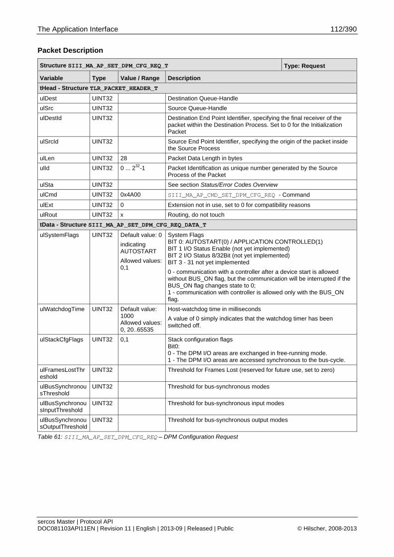
The Application Interface 112/390
sercos Master | Protocol API DOC081103API11EN | Revision 11 | English | 2013-09 | Released | Public © Hilscher, 2008-2013
Packet Description
Structure SIII_MA_AP_SET_DPM_CFG_REQ_T Type: Request
Variable Type Value / Range Description
tHead - Structure TLR_PACKET_HEADER_T
ulDest UINT32 Destination Queue-Handle
ulSrc UINT32 Source Queue-Handle
ulDestId UINT32 Destination End Point Identifier, specifying the final receiver of the packet within the Destination Process. Set to 0 for the Initialization Packet
ulSrcId UINT32 Source End Point Identifier, specifying the origin of the packet inside the Source Process
ulLen UINT32 28 Packet Data Length in bytes
ulId UINT32 0 ... 232-1 Packet Identification as unique number generated by the Source Process of the Packet
ulSta UINT32 See section Status/Error Codes Overview
ulCmd UINT32 0x4A00 SIII_MA_AP_CMD_SET_DPM_CFG_REQ - Command
ulExt UINT32 0 Extension not in use, set to 0 for compatibility reasons
ulRout UINT32 x Routing, do not touch
tData - Structure SIII_MA_AP_SET_DPM_CFG_REQ_DATA_T
ulSystemFlags UINT32 Default value: 0
indicating AUTOSTART
Allowed values: 0,1
System Flags BIT 0: AUTOSTART(0) / APPLICATION CONTROLLED(1) BIT 1 I/O Status Enable (not yet implemented) BIT 2 I/O Status 8/32Bit (not yet implemented) BIT 3 - 31 not yet implemented
0 - communication with a controller after a device start is allowed without BUS_ON flag, but the communication will be interrupted if the BUS_ON flag changes state to 0; 1 - communication with controller is allowed only with the BUS_ON flag.
ulWatchdogTime UINT32 Default value: 1000 Allowed values: 0, 20..65535
Host-watchdog time in milliseconds
A value of 0 simply indicates that the watchdog timer has been switched off.
ulStackCfgFlags UINT32 0,1 Stack configuration flags Bit0: 0 - The DPM I/O areas are exchanged in free-running mode. 1 - The DPM I/O areas are accessed synchronous to the bus-cycle.
ulFramesLostThreshold
UINT32 Threshold for Frames Lost (reserved for future use, set to zero)
ulBusSynchronousThreshold
UINT32 Threshold for bus-synchronous modes
ulBusSynchronousInputThreshold
UINT32 Threshold for bus-synchronous input modes
ulBusSynchronousOutputThreshold
UINT32 Threshold for bus-synchronous output modes
Table 61: SIII_MA_AP_SET_DPM_CFG_REQ – DPM Configuration Request
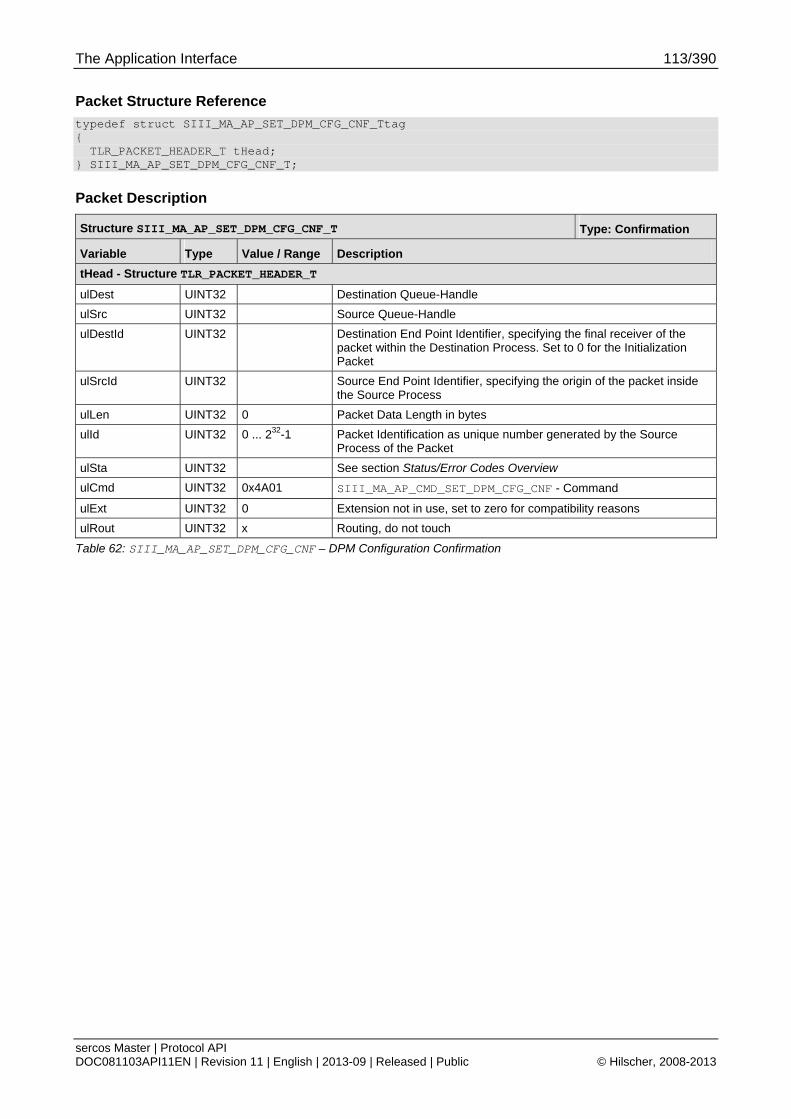
The Application Interface 113/390
sercos Master | Protocol API DOC081103API11EN | Revision 11 | English | 2013-09 | Released | Public © Hilscher, 2008-2013
Packet Structure Reference
typedef struct SIII_MA_AP_SET_DPM_CFG_CNF_Ttag { TLR_PACKET_HEADER_T tHead; } SIII_MA_AP_SET_DPM_CFG_CNF_T;
Packet Description
Structure SIII_MA_AP_SET_DPM_CFG_CNF_T Type: Confirmation
Variable Type Value / Range Description
tHead - Structure TLR_PACKET_HEADER_T
ulDest UINT32 Destination Queue-Handle
ulSrc UINT32 Source Queue-Handle
ulDestId UINT32 Destination End Point Identifier, specifying the final receiver of the packet within the Destination Process. Set to 0 for the Initialization Packet
ulSrcId UINT32 Source End Point Identifier, specifying the origin of the packet inside the Source Process
ulLen UINT32 0 Packet Data Length in bytes
ulId UINT32 0 ... 232-1 Packet Identification as unique number generated by the Source Process of the Packet
ulSta UINT32 See section Status/Error Codes Overview
ulCmd UINT32 0x4A01 SIII_MA_AP_CMD_SET_DPM_CFG_CNF - Command
ulExt UINT32 0 Extension not in use, set to zero for compatibility reasons
ulRout UINT32 x Routing, do not touch
Table 62: SIII_MA_AP_SET_DPM_CFG_CNF – DPM Configuration Confirmation
The Application Interface 114/390
sercos Master | Protocol API DOC081103API11EN | Revision 11 | English | 2013-09 | Released | Public © Hilscher, 2008-2013
6.1.7 Automatic Configuration of Frame Layout with automatic Timing Calculation
6.1.7.1 Begin Configuration Transfer Parameters for automatic Configuration of Frame Layout with automatic Timing Calculation
This variant is selected by having bits 2 and 5 set in ulStackConfigurationFlags.
The following parameters are used and must be specified:
Communication Cycle Time (tScyc)
Communication Timeout
Process Data Output Size (MDT)
Process Data Input Size (AT)
Minimum CP0 Wait Cycles
The following parameters have no influence in this variant and can be set to zero since they are calculated internally:
AT Transmission Starting Time (t1)
NRT transmission start time (t6)
NRT transmission end time (t7)
NRT channel MTU
Command value valid time
For details on these parameters, see 4.2.3 Detailed Description of Master Parameters.
For configuration packets usage and flow diagram, see chapter 6.1.9 Usage and Flow Diagram of automatic Configuration Packets.
The stack configuration flags as needed for this configuration variant are given in the following chapter.
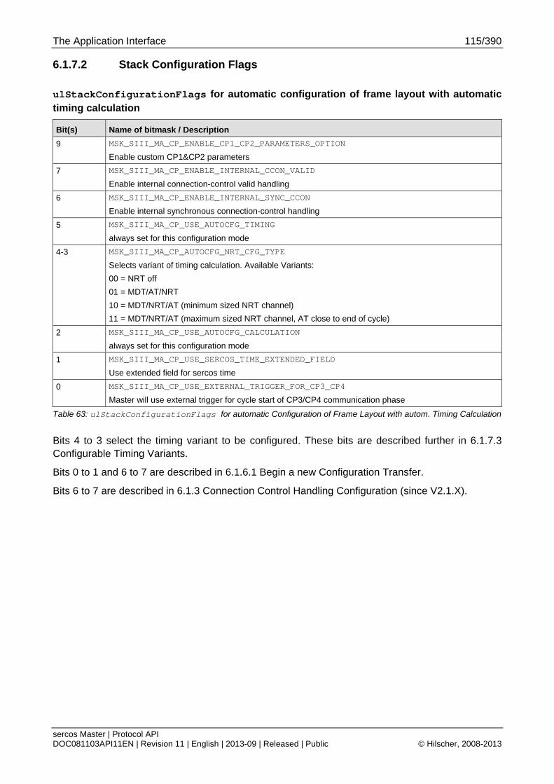
The Application Interface 115/390
sercos Master | Protocol API DOC081103API11EN | Revision 11 | English | 2013-09 | Released | Public © Hilscher, 2008-2013
6.1.7.2 Stack Configuration Flags
ulStackConfigurationFlags for automatic configuration of frame layout with automatic timing calculation
Bit(s) Name of bitmask / Description
9 MSK_SIII_MA_CP_ENABLE_CP1_CP2_PARAMETERS_OPTION
Enable custom CP1&CP2 parameters
7 MSK_SIII_MA_CP_ENABLE_INTERNAL_CCON_VALID
Enable internal connection-control valid handling
6 MSK_SIII_MA_CP_ENABLE_INTERNAL_SYNC_CCON
Enable internal synchronous connection-control handling
5 MSK_SIII_MA_CP_USE_AUTOCFG_TIMING
always set for this configuration mode
4-3 MSK_SIII_MA_CP_AUTOCFG_NRT_CFG_TYPE
Selects variant of timing calculation. Available Variants:
00 = NRT off
01 = MDT/AT/NRT
10 = MDT/NRT/AT (minimum sized NRT channel)
11 = MDT/NRT/AT (maximum sized NRT channel, AT close to end of cycle)
2 MSK_SIII_MA_CP_USE_AUTOCFG_CALCULATION
always set for this configuration mode
1 MSK_SIII_MA_CP_USE_SERCOS_TIME_EXTENDED_FIELD
Use extended field for sercos time
0 MSK_SIII_MA_CP_USE_EXTERNAL_TRIGGER_FOR_CP3_CP4
Master will use external trigger for cycle start of CP3/CP4 communication phase
Table 63: ulStackConfigurationFlags for automatic Configuration of Frame Layout with autom. Timing Calculation
Bits 4 to 3 select the timing variant to be configured. These bits are described further in 6.1.7.3 Configurable Timing Variants.
Bits 0 to 1 and 6 to 7 are described in 6.1.6.1 Begin a new Configuration Transfer.
Bits 6 to 7 are described in 6.1.3 Connection Control Handling Configuration (since V2.1.X).
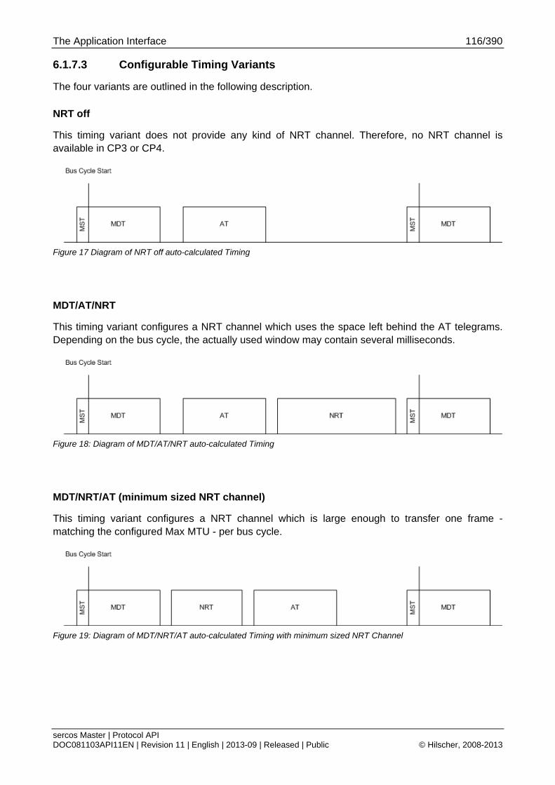
The Application Interface 116/390
sercos Master | Protocol API DOC081103API11EN | Revision 11 | English | 2013-09 | Released | Public © Hilscher, 2008-2013
6.1.7.3 Configurable Timing Variants
The four variants are outlined in the following description.
NRT off
This timing variant does not provide any kind of NRT channel. Therefore, no NRT channel is available in CP3 or CP4.
Figure 17 Diagram of NRT off auto-calculated Timing
MDT/AT/NRT
This timing variant configures a NRT channel which uses the space left behind the AT telegrams. Depending on the bus cycle, the actually used window may contain several milliseconds.
Figure 18: Diagram of MDT/AT/NRT auto-calculated Timing
MDT/NRT/AT (minimum sized NRT channel)
This timing variant configures a NRT channel which is large enough to transfer one frame - matching the configured Max MTU - per bus cycle.
Figure 19: Diagram of MDT/NRT/AT auto-calculated Timing with minimum sized NRT Channel

The Application Interface 117/390
sercos Master | Protocol API DOC081103API11EN | Revision 11 | English | 2013-09 | Released | Public © Hilscher, 2008-2013
MDT/NRT/AT (maximum sized NRT channel)
This timing variant configures a NRT channel which spans most of the bus cycle. It is sufficiently dimensioned to exchange multiple non-real time frames of the configured Max MTU size.
Figure 20: Diagram of MDT/NRT/AT auto-calculated Timing with maximum sized NRT Channel
6.1.8 Automatic Configuration of Frame Layout with user specified Timing Parameters
6.1.8.1 Begin Configuration Transfer Parameters for automatic configuration of Frame Layout with user specified Timing Parameters
This variant is selected by having bit 2 set and 5 cleared in ulStackConfigurationFlags.
The following parameters are used and must be specified:
Communication Cycle Time (tScyc)
Communication Timeout
AT Transmission Starting Time (t1)
NRT transmission start time (t6)
NRT transmission end time (t7)
Command value valid time
Synchronization time (t4)
NRT channel MTU
Process Data Output Size (MDT)
Process Data Input Size (AT)
Minimum CP0 Wait Cycles
For details on these parameters, see 4.2.3 Detailed Description of Master Parameters.
For configuration packets usage and flow diagram, see chapter 6.1.9 Usage and Flow Diagram of automatic Configuration Packets.
The stack configuration flags as needed for this configuration variant are given in the following chapter.
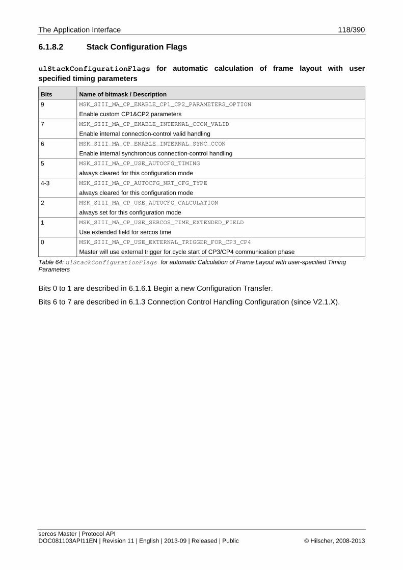
The Application Interface 118/390
sercos Master | Protocol API DOC081103API11EN | Revision 11 | English | 2013-09 | Released | Public © Hilscher, 2008-2013
6.1.8.2 Stack Configuration Flags
ulStackConfigurationFlags for automatic calculation of frame layout with user specified timing parameters
Bits Name of bitmask / Description
9 MSK_SIII_MA_CP_ENABLE_CP1_CP2_PARAMETERS_OPTION
Enable custom CP1&CP2 parameters
7 MSK_SIII_MA_CP_ENABLE_INTERNAL_CCON_VALID
Enable internal connection-control valid handling
6 MSK_SIII_MA_CP_ENABLE_INTERNAL_SYNC_CCON
Enable internal synchronous connection-control handling
5 MSK_SIII_MA_CP_USE_AUTOCFG_TIMING
always cleared for this configuration mode
4-3 MSK_SIII_MA_CP_AUTOCFG_NRT_CFG_TYPE
always cleared for this configuration mode
2 MSK_SIII_MA_CP_USE_AUTOCFG_CALCULATION
always set for this configuration mode
1 MSK_SIII_MA_CP_USE_SERCOS_TIME_EXTENDED_FIELD
Use extended field for sercos time
0 MSK_SIII_MA_CP_USE_EXTERNAL_TRIGGER_FOR_CP3_CP4
Master will use external trigger for cycle start of CP3/CP4 communication phase
Table 64: ulStackConfigurationFlags for automatic Calculation of Frame Layout with user-specified Timing Parameters
Bits 0 to 1 are described in 6.1.6.1 Begin a new Configuration Transfer.
Bits 6 to 7 are described in 6.1.3 Connection Control Handling Configuration (since V2.1.X).
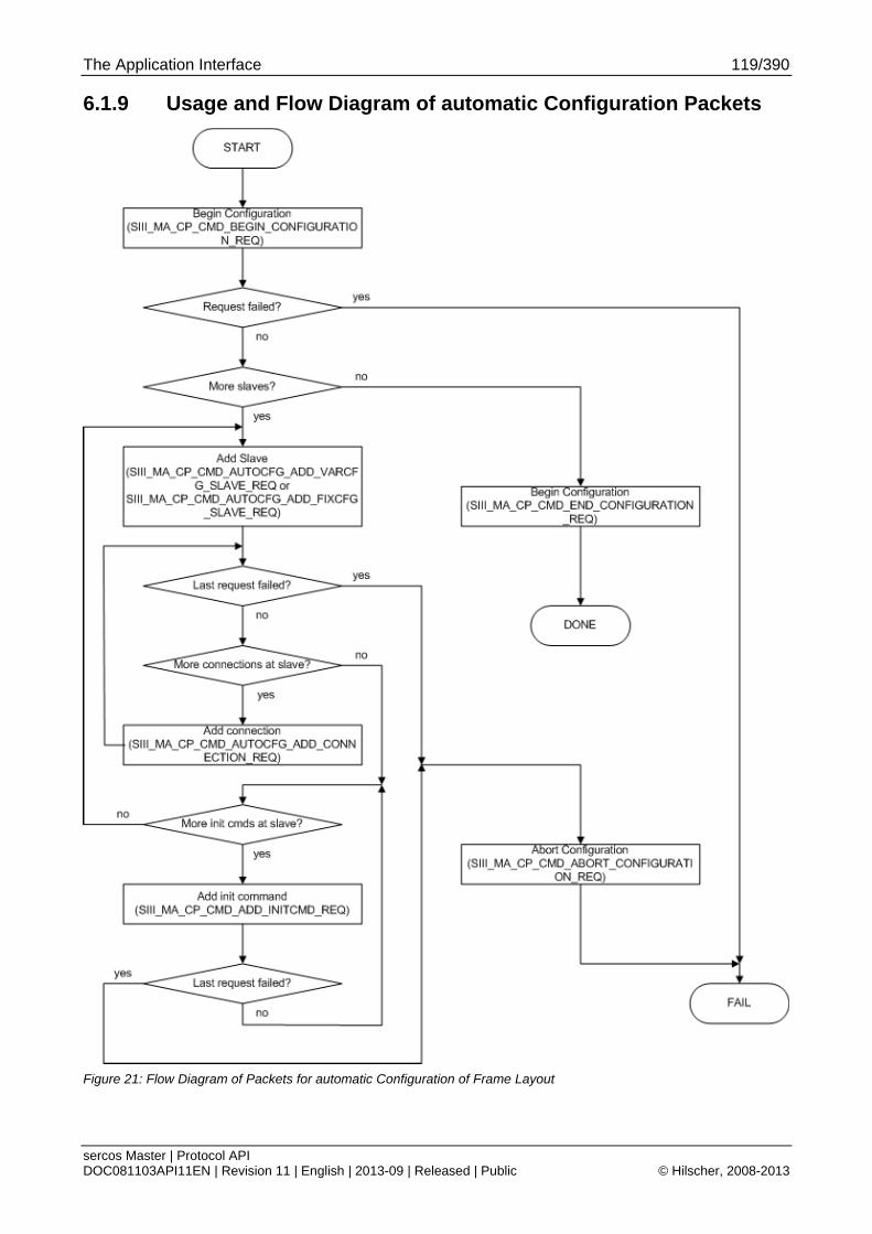
The Application Interface 119/390
sercos Master | Protocol API DOC081103API11EN | Revision 11 | English | 2013-09 | Released | Public © Hilscher, 2008-2013
6.1.9 Usage and Flow Diagram of automatic Configuration Packets
Figure 21: Flow Diagram of Packets for automatic Configuration of Frame Layout
The Application Interface 120/390
sercos Master | Protocol API DOC081103API11EN | Revision 11 | English | 2013-09 | Released | Public © Hilscher, 2008-2013
6.1.9.1 Usage
The packets have to be used in a specific order. The flow chart above shows the sequence of the packets in which they have to be used.
The packet SIII_MA_CP_CMD_ABORT_CONFIGURATION_REQ has to be used whenever a configuration is not going to be completed due to some error result of the packets in between.
The details on packet contents are given in the following chapters:
6.1.6 Common Services (all Packet Configuration Variants)
6.1.7 Automatic Configuration of Frame Layout with automatic Timing Calculation
(only when automatic timing calculation is selected)
6.1.8 Automatic Configuration of Frame Layout with user specified Timing Parameters
(only when user specified timing parameters are used)
6.1.10 Packets used for automatic Configuration (AutoCfg) of Frame Layout
Note: After finishing 6.1.6.2 End a Configuration Transfer Service when using LFW/SHM API, the 6.1.6.7 DPM Configuration Service must be used for configuring the DPM AP task.
Step Add connection
This step is optional since the packet for adding a slave already allows to add connection configuration for the most common case where the connection instance are consecutively used without any gaps (i.e. connection instances 0 to n).
Step Add init command
This step is necessary for SCP_VarCFG slaves since these require parameter writes onto their IDN dictionary.
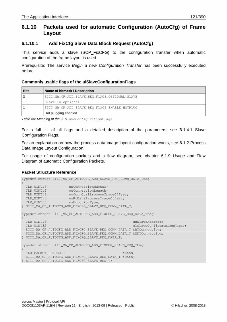
The Application Interface 121/390
sercos Master | Protocol API DOC081103API11EN | Revision 11 | English | 2013-09 | Released | Public © Hilscher, 2008-2013
6.1.10 Packets used for automatic Configuration (AutoCfg) of Frame Layout
6.1.10.1 Add FixCfg Slave Data Block Request (AutoCfg)
This service adds a slave (SCP_FixCFG) to the configuration transfer when automatic configuration of the frame layout is used.
Prerequisite: The service Begin a new Configuration Transfer has been successfully executed before.
Commonly usable flags of the ulSlaveConfigurationFlags
Bits Name of bitmask / Description
3 SIII_MA_CP_ADD_SLAVE_REQ_FLAGS_OPTIONAL_SLAVE
Slave is optional
1 SIII_MA_CP_ADD_SLAVE_REQ_FLAGS_ENABLE_HOTPLUG
Hot plugging enabled
Table 65: Meaning of the ulSlaveConfigurationFlags
For a full list of all flags and a detailed description of the parameters, see 6.1.4.1 Slave Configuration Flags.
For an explanation on how the process data image layout configuration works, see 6.1.2 Process Data Image Layout Configuration.
For usage of configuration packets and a flow diagram, see chapter 6.1.9 Usage and Flow Diagram of automatic Configuration Packets.
Packet Structure Reference
Typedef struct SIII_MA_CP_AUTOCFG_ADD_SLAVE_REQ_CONN_DATA_Ttag { TLR_UINT16 usConnectionNumber; TLR_UINT16 usConnectionLength; TLR_UINT16 usConnCtrlProcessImageOffset; TLR_UINT16 usRtDataProcessImageOffset; TLR_UINT16 usFunctionType; } SIII_MA_CP_AUTOCFG_ADD_FIXCFG_SLAVE_REQ_CONN_DATA_T; typedef struct SIII_MA_CP_AUTOCFG_ADD_FIXCFG_SLAVE_REQ_DATA_Ttag { TLR_UINT16 usSlaveAddress; TLR_UINT32 ulSlaveConfigurationFlags; SIII_MA_CP_AUTOCFG_ADD_FIXCFG_SLAVE_REQ_CONN_DATA_T tATConnection; SIII_MA_CP_AUTOCFG_ADD_FIXCFG_SLAVE_REQ_CONN_DATA_T tMDTConnection; } SIII_MA_CP_AUTOCFG_ADD_FIXCFG_SLAVE_REQ_DATA_T; typedef struct SIII_MA_CP_AUTOCFG_ADD_FIXCFG_SLAVE_REQ_Ttag { TLR_PACKET_HEADER_T tHead; SIII_MA_CP_AUTOCFG_ADD_FIXCFG_SLAVE_REQ_DATA_T tData; } SIII_MA_CP_AUTOCFG_ADD_FIXCFG_SLAVE_REQ_T;
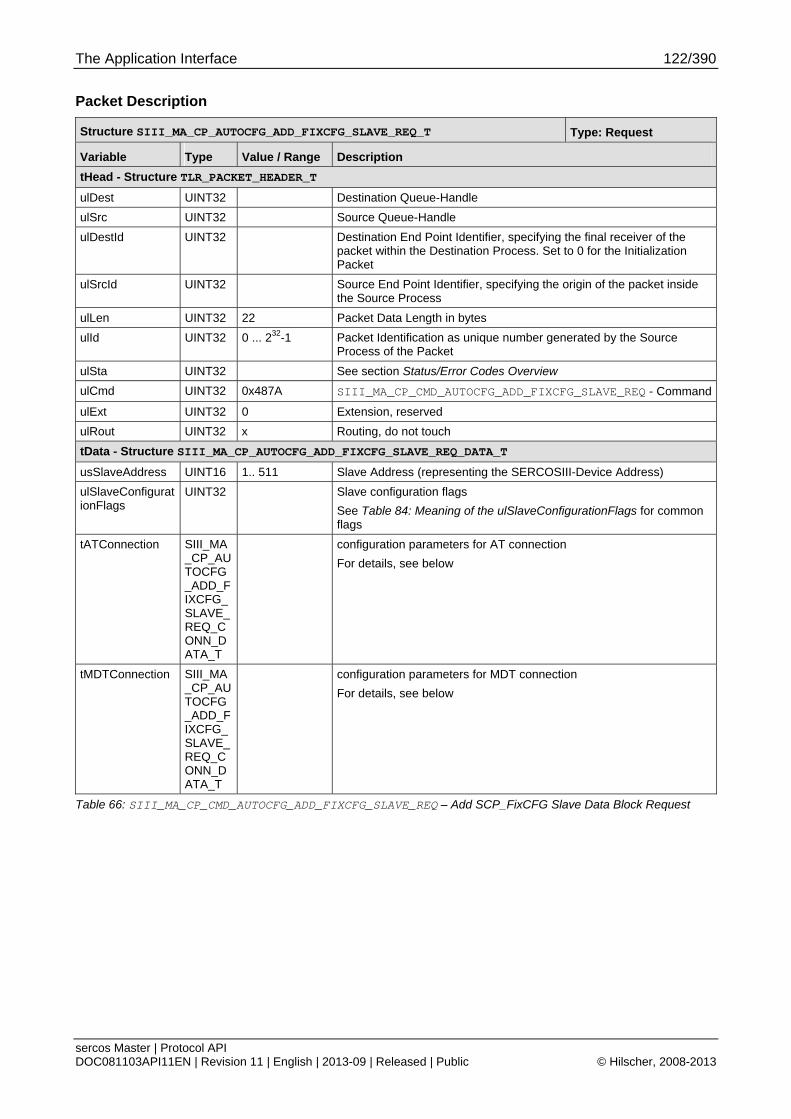
The Application Interface 122/390
sercos Master | Protocol API DOC081103API11EN | Revision 11 | English | 2013-09 | Released | Public © Hilscher, 2008-2013
Packet Description
Structure SIII_MA_CP_AUTOCFG_ADD_FIXCFG_SLAVE_REQ_T Type: Request
Variable Type Value / Range Description
tHead - Structure TLR_PACKET_HEADER_T
ulDest UINT32 Destination Queue-Handle
ulSrc UINT32 Source Queue-Handle
ulDestId UINT32 Destination End Point Identifier, specifying the final receiver of the packet within the Destination Process. Set to 0 for the Initialization Packet
ulSrcId UINT32 Source End Point Identifier, specifying the origin of the packet inside the Source Process
ulLen UINT32 22 Packet Data Length in bytes
ulId UINT32 0 ... 232-1 Packet Identification as unique number generated by the Source Process of the Packet
ulSta UINT32 See section Status/Error Codes Overview
ulCmd UINT32 0x487A SIII_MA_CP_CMD_AUTOCFG_ADD_FIXCFG_SLAVE_REQ - Command
ulExt UINT32 0 Extension, reserved
ulRout UINT32 x Routing, do not touch
tData - Structure SIII_MA_CP_AUTOCFG_ADD_FIXCFG_SLAVE_REQ_DATA_T
usSlaveAddress UINT16 1.. 511 Slave Address (representing the SERCOSIII-Device Address)
ulSlaveConfigurationFlags
UINT32 Slave configuration flags
See Table 84: Meaning of the ulSlaveConfigurationFlags for common flags
tATConnection SIII_MA_CP_AUTOCFG_ADD_FIXCFG_SLAVE_REQ_CONN_DATA_T
configuration parameters for AT connection
For details, see below
tMDTConnection SIII_MA_CP_AUTOCFG_ADD_FIXCFG_SLAVE_REQ_CONN_DATA_T
configuration parameters for MDT connection
For details, see below
Table 66: SIII_MA_CP_CMD_AUTOCFG_ADD_FIXCFG_SLAVE_REQ – Add SCP_FixCFG Slave Data Block Request
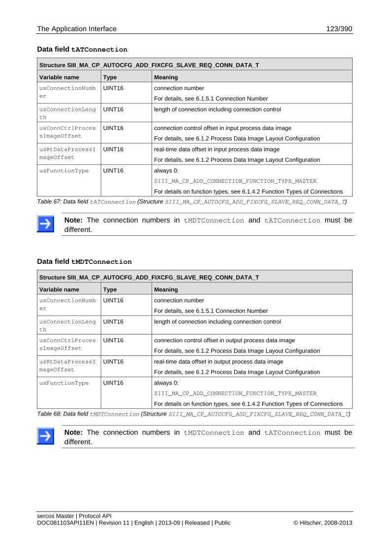
The Application Interface 123/390
sercos Master | Protocol API DOC081103API11EN | Revision 11 | English | 2013-09 | Released | Public © Hilscher, 2008-2013
Data field tATConnection
Structure SIII_MA_CP_AUTOCFG_ADD_FIXCFG_SLAVE_REQ_CONN_DATA_T
Variable name Type Meaning
usConnectionNumber
UINT16 connection number
For details, see 6.1.5.1 Connection Number
usConnectionLength
UINT16 length of connection including connection control
usConnCtrlProcessImageOffset
UINT16 connection control offset in input process data image
For details, see 6.1.2 Process Data Image Layout Configuration
usRtDataProcessImageOffset
UINT16 real-time data offset in input process data image
For details, see 6.1.2 Process Data Image Layout Configuration
usFunctionType UINT16 always 0:
SIII_MA_CP_ADD_CONNECTION_FUNCTION_TYPE_MASTER
For details on function types, see 6.1.4.2 Function Types of Connections
Table 67: Data field tATConnection (Structure SIII_MA_CP_AUTOCFG_ADD_FIXCFG_SLAVE_REQ_CONN_DATA_T)
Note: The connection numbers in tMDTConnection and tATConnection must be different.
Data field tMDTConnection
Structure SIII_MA_CP_AUTOCFG_ADD_FIXCFG_SLAVE_REQ_CONN_DATA_T
Variable name Type Meaning
usConnectionNumber
UINT16 connection number
For details, see 6.1.5.1 Connection Number
usConnectionLength
UINT16 length of connection including connection control
usConnCtrlProcessImageOffset
UINT16 connection control offset in output process data image
For details, see 6.1.2 Process Data Image Layout Configuration
usRtDataProcessImageOffset
UINT16 real-time data offset in output process data image
For details, see 6.1.2 Process Data Image Layout Configuration
usFunctionType UINT16 always 0:
SIII_MA_CP_ADD_CONNECTION_FUNCTION_TYPE_MASTER
For details on function types, see 6.1.4.2 Function Types of Connections
Table 68: Data field tMDTConnection (Structure SIII_MA_CP_AUTOCFG_ADD_FIXCFG_SLAVE_REQ_CONN_DATA_T)
Note: The connection numbers in tMDTConnection and tATConnection must be different.

The Application Interface 124/390
sercos Master | Protocol API DOC081103API11EN | Revision 11 | English | 2013-09 | Released | Public © Hilscher, 2008-2013
Packet Structure Reference
typedef struct SIII_MA_CP_AUTOCFG_ADD_FIXCFG_SLAVE_CNF_Ttag { TLR_PACKET_HEADER_T tHead; } SIII_MA_CP_AUTOCFG_ADD_FIXCFG_SLAVE_CNF_T;
Packet Description
Structure SIII_MA_CP_AUTOCFG_ADD_FIXCFG_SLAVE_CNF_T Type: Confirmation
Variable Type Value / Range Description
tHead - Structure TLR_PACKET_HEADER_T
ulDest UINT32 Destination queue handle, unchanged
ulSrc UINT32 Source queue handle, unchanged
ulDestId UINT32 Destination End Point Identifier, specifying the final receiver of the packet within the Destination Process. Set to 0 for the Initialization Packet
ulSrcId UINT32 Source End Point Identifier, specifying the origin of the packet inside the Source Process
ulLen UINT32 0 Packet Data Length in bytes
ulId UINT32 0 ... 232-1 Packet Identification as unique number generated by the Source Process of the Packet
ulSta UINT32 See section Status/Error Codes Overview
ulCmd UINT32 0x487B SIII_MA_CP_CMD_AUTOCFG_ADD_FIXCFG_SLAVE_CNF - Command
ulExt UINT32 0 Extension not in use, set to zero for compatibility reasons
ulRout UINT32 x Routing, do not touch
Table 69: SIII_MA_CP_CMD_AUTOCFG_ADD_FIXCFG_SLAVE_CNF – Add SCP_FIXCFG Slave Data Block Confirmation
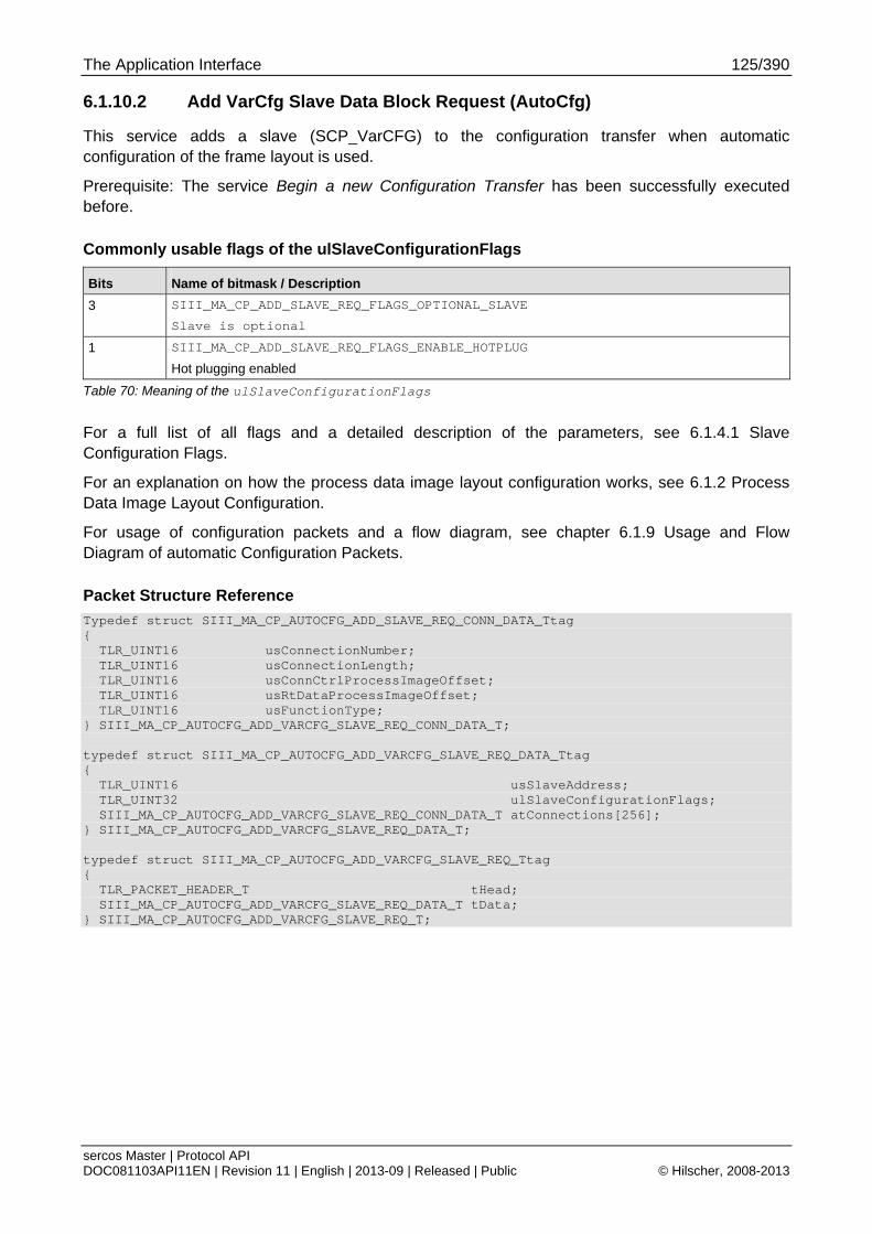
The Application Interface 125/390
sercos Master | Protocol API DOC081103API11EN | Revision 11 | English | 2013-09 | Released | Public © Hilscher, 2008-2013
6.1.10.2 Add VarCfg Slave Data Block Request (AutoCfg)
This service adds a slave (SCP_VarCFG) to the configuration transfer when automatic configuration of the frame layout is used.
Prerequisite: The service Begin a new Configuration Transfer has been successfully executed before.
Commonly usable flags of the ulSlaveConfigurationFlags
Bits Name of bitmask / Description
3 SIII_MA_CP_ADD_SLAVE_REQ_FLAGS_OPTIONAL_SLAVE
Slave is optional
1 SIII_MA_CP_ADD_SLAVE_REQ_FLAGS_ENABLE_HOTPLUG
Hot plugging enabled
Table 70: Meaning of the ulSlaveConfigurationFlags
For a full list of all flags and a detailed description of the parameters, see 6.1.4.1 Slave Configuration Flags.
For an explanation on how the process data image layout configuration works, see 6.1.2 Process Data Image Layout Configuration.
For usage of configuration packets and a flow diagram, see chapter 6.1.9 Usage and Flow Diagram of automatic Configuration Packets.
Packet Structure Reference
Typedef struct SIII_MA_CP_AUTOCFG_ADD_SLAVE_REQ_CONN_DATA_Ttag { TLR_UINT16 usConnectionNumber; TLR_UINT16 usConnectionLength; TLR_UINT16 usConnCtrlProcessImageOffset; TLR_UINT16 usRtDataProcessImageOffset; TLR_UINT16 usFunctionType; } SIII_MA_CP_AUTOCFG_ADD_VARCFG_SLAVE_REQ_CONN_DATA_T; typedef struct SIII_MA_CP_AUTOCFG_ADD_VARCFG_SLAVE_REQ_DATA_Ttag { TLR_UINT16 usSlaveAddress; TLR_UINT32 ulSlaveConfigurationFlags; SIII_MA_CP_AUTOCFG_ADD_VARCFG_SLAVE_REQ_CONN_DATA_T atConnections[256]; } SIII_MA_CP_AUTOCFG_ADD_VARCFG_SLAVE_REQ_DATA_T; typedef struct SIII_MA_CP_AUTOCFG_ADD_VARCFG_SLAVE_REQ_Ttag { TLR_PACKET_HEADER_T tHead; SIII_MA_CP_AUTOCFG_ADD_VARCFG_SLAVE_REQ_DATA_T tData; } SIII_MA_CP_AUTOCFG_ADD_VARCFG_SLAVE_REQ_T;
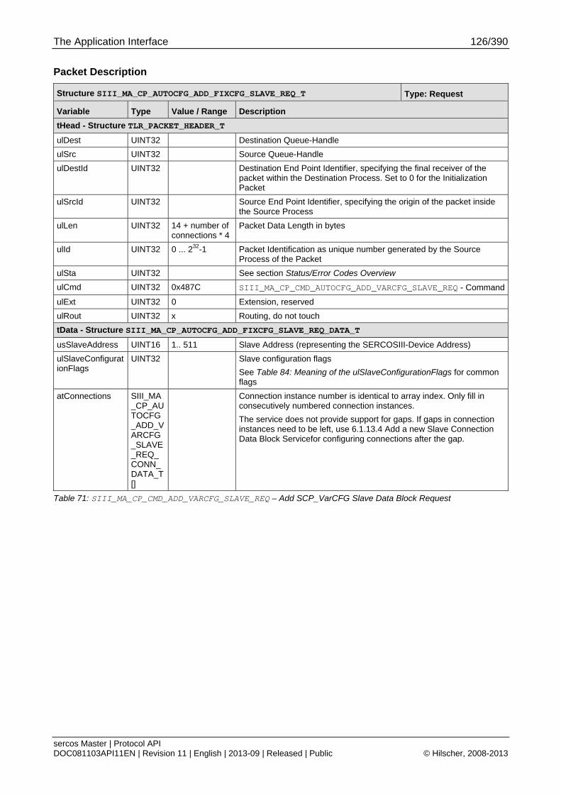
The Application Interface 126/390
sercos Master | Protocol API DOC081103API11EN | Revision 11 | English | 2013-09 | Released | Public © Hilscher, 2008-2013
Packet Description
Structure SIII_MA_CP_AUTOCFG_ADD_FIXCFG_SLAVE_REQ_T Type: Request
Variable Type Value / Range Description
tHead - Structure TLR_PACKET_HEADER_T
ulDest UINT32 Destination Queue-Handle
ulSrc UINT32 Source Queue-Handle
ulDestId UINT32 Destination End Point Identifier, specifying the final receiver of the packet within the Destination Process. Set to 0 for the Initialization Packet
ulSrcId UINT32 Source End Point Identifier, specifying the origin of the packet inside the Source Process
ulLen UINT32 14 + number of connections * 4
Packet Data Length in bytes
ulId UINT32 0 ... 232-1 Packet Identification as unique number generated by the Source Process of the Packet
ulSta UINT32 See section Status/Error Codes Overview
ulCmd UINT32 0x487C SIII_MA_CP_CMD_AUTOCFG_ADD_VARCFG_SLAVE_REQ - Command
ulExt UINT32 0 Extension, reserved
ulRout UINT32 x Routing, do not touch
tData - Structure SIII_MA_CP_AUTOCFG_ADD_FIXCFG_SLAVE_REQ_DATA_T
usSlaveAddress UINT16 1.. 511 Slave Address (representing the SERCOSIII-Device Address)
ulSlaveConfigurationFlags
UINT32 Slave configuration flags
See Table 84: Meaning of the ulSlaveConfigurationFlags for common flags
atConnections SIII_MA_CP_AUTOCFG_ADD_VARCFG_SLAVE_REQ_CONN_DATA_T[]
Connection instance number is identical to array index. Only fill in consecutively numbered connection instances.
The service does not provide support for gaps. If gaps in connection instances need to be left, use 6.1.13.4 Add a new Slave Connection Data Block Servicefor configuring connections after the gap.
Table 71: SIII_MA_CP_CMD_ADD_VARCFG_SLAVE_REQ – Add SCP_VarCFG Slave Data Block Request
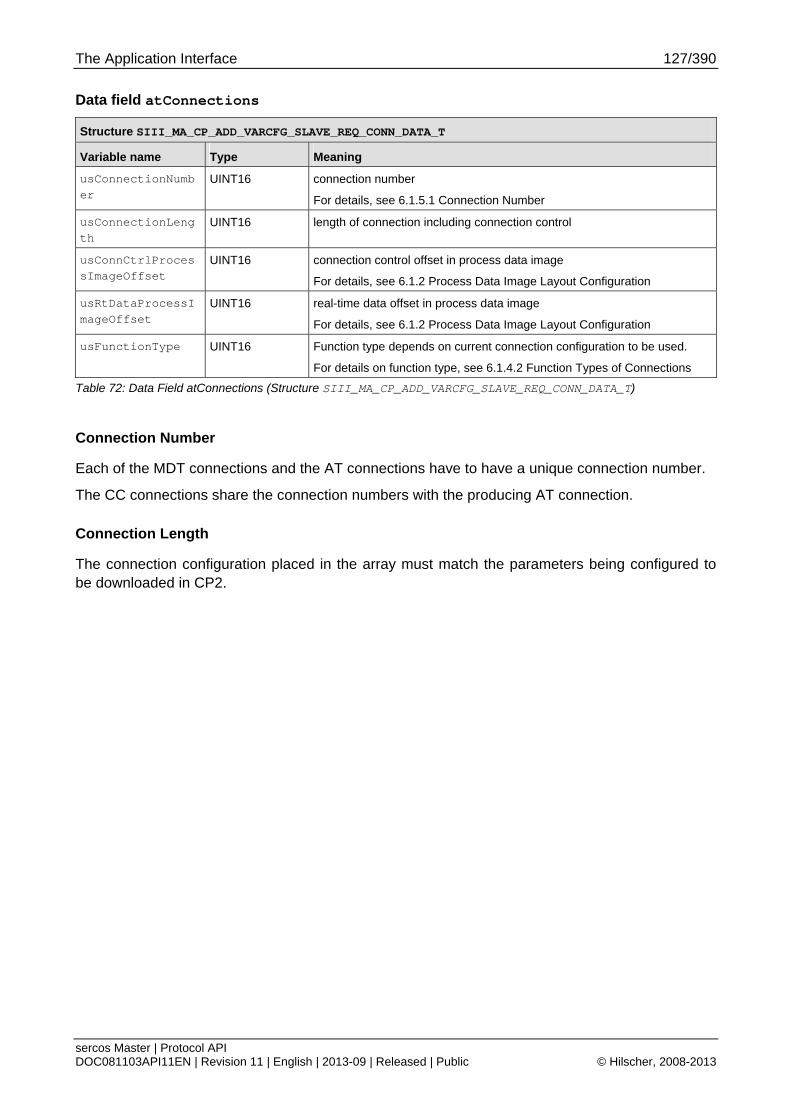
The Application Interface 127/390
sercos Master | Protocol API DOC081103API11EN | Revision 11 | English | 2013-09 | Released | Public © Hilscher, 2008-2013
Data field atConnections
Structure SIII_MA_CP_ADD_VARCFG_SLAVE_REQ_CONN_DATA_T
Variable name Type Meaning
usConnectionNumber
UINT16 connection number
For details, see 6.1.5.1 Connection Number
usConnectionLength
UINT16 length of connection including connection control
usConnCtrlProcessImageOffset
UINT16 connection control offset in process data image
For details, see 6.1.2 Process Data Image Layout Configuration
usRtDataProcessImageOffset
UINT16 real-time data offset in process data image
For details, see 6.1.2 Process Data Image Layout Configuration
usFunctionType UINT16 Function type depends on current connection configuration to be used.
For details on function type, see 6.1.4.2 Function Types of Connections
Table 72: Data Field atConnections (Structure SIII_MA_CP_ADD_VARCFG_SLAVE_REQ_CONN_DATA_T)
Connection Number
Each of the MDT connections and the AT connections have to have a unique connection number.
The CC connections share the connection numbers with the producing AT connection.
Connection Length
The connection configuration placed in the array must match the parameters being configured to be downloaded in CP2.

The Application Interface 128/390
sercos Master | Protocol API DOC081103API11EN | Revision 11 | English | 2013-09 | Released | Public © Hilscher, 2008-2013
Packet Structure Reference
typedef struct SIII_MA_CP_ADD_VARCFG_SLAVE_CNF_Ttag { TLR_PACKET_HEADER_T tHead; } SIII_MA_CP_ADD_VARCFG_SLAVE_CNF_T;
Packet Description
Structure SIII_MA_CP_ADD_VARCFG_SLAVE_CNF_T Type: Confirmation
Variable Type Value / Range Description
tHead - Structure TLR_PACKET_HEADER_T
ulDest UINT32 Destination queue handle, unchanged
ulSrc UINT32 Source queue handle, unchanged
ulDestId UINT32 Destination End Point Identifier, specifying the final receiver of the packet within the Destination Process. Set to 0 for the Initialization Packet
ulSrcId UINT32 Source End Point Identifier, specifying the origin of the packet inside the Source Process
ulLen UINT32 0 Packet Data Length in bytes
ulId UINT32 0 ... 232-1 Packet Identification as unique number generated by the Source Process of the Packet
ulSta UINT32 See section Status/Error Codes Overview
ulCmd UINT32 0x4879 SIII_MA_CP_CMD_ADD_VARCFG_SLAVE_CNF - Command
ulExt UINT32 0 Extension not in use, set to zero for compatibility reasons
ulRout UINT32 x Routing, do not touch
Table 73: SIII_MA_CP_CMD_ADD_VARCFG_SLAVE_CNF – Add SCP_VarCFG Slave Data Block Confirmation

The Application Interface 129/390
sercos Master | Protocol API DOC081103API11EN | Revision 11 | English | 2013-09 | Released | Public © Hilscher, 2008-2013
6.1.10.3 Add Slave Connection Data Block Request (AutoCfg)
This service adds a slave connection to a configuration transfer when automatic configuration of the frame layout is used.
Prerequisite: The service Begin a new Configuration Transfer has been successfully executed before.
The configuration data consist of connection parameters and the mapping to the process data image. In addition, the function type of the connection is configured.
For an explanation on how the process data image layout configuration works, see 6.1.2 Process Data Image Layout Configuration.
For a detailed explanation of function types, see 6.1.4.2 Function Types of Connections.
For usage of configuration packets and a flow diagram, see chapter 6.1.9 Usage and Flow Diagram of automatic Configuration Packets.
Packet Structure Reference
typedef struct SIII_MA_CP_AUTOCFG_ADD_CONNECTION_REQ_DATA_Ttag { TLR_UINT16 usSlaveAddress; TLR_UINT8 bConnectionInstance; TLR_UINT8 bReserved; TLR_UINT16 usConnectionNumber; TLR_UINT16 usConnectionLength; TLR_UINT16 usConnCtrlProcessImageOffset; TLR_UINT16 usRtDataProcessImageOffset; TLR_UINT16 usFunctionType; } SIII_MA_CP_AUTOCFG_ADD_CONNECTION_REQ_DATA_T; #define SIII_MA_CP_ADD_CONNECTION_FUNCTION_TYPE_MASTER_AT 0x0000 #define SIII_MA_CP_ADD_CONNECTION_FUNCTION_TYPE_MASTER_MDT 0x8000 #define SIII_MA_CP_ADD_CONNECTION_FUNCTION_TYPE_CC 0x0001 typedef struct SIII_MA_CP_AUTOCFG_ADD_CONNECTION_REQ_Ttag { TLR_PACKET_HEADER_T tHead; SIII_MA_CP_AUTOCFG_ADD_CONNECTION_REQ_DATA_T tData; } SIII_MA_CP_AUTOCFG_ADD_CONNECTION_REQ_T;
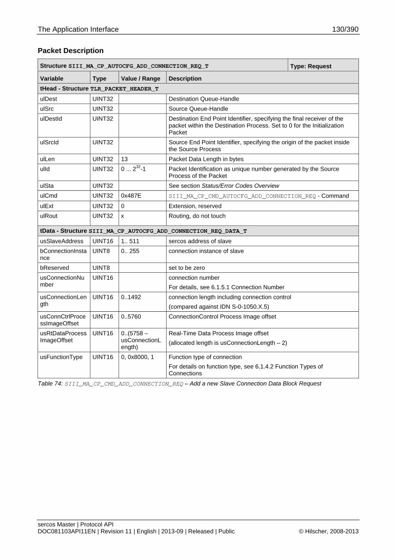
The Application Interface 130/390
sercos Master | Protocol API DOC081103API11EN | Revision 11 | English | 2013-09 | Released | Public © Hilscher, 2008-2013
Packet Description
Structure SIII_MA_CP_AUTOCFG_ADD_CONNECTION_REQ_T Type: Request
Variable Type Value / Range Description
tHead - Structure TLR_PACKET_HEADER_T
ulDest UINT32 Destination Queue-Handle
ulSrc UINT32 Source Queue-Handle
ulDestId UINT32 Destination End Point Identifier, specifying the final receiver of the packet within the Destination Process. Set to 0 for the Initialization Packet
ulSrcId UINT32 Source End Point Identifier, specifying the origin of the packet inside the Source Process
ulLen UINT32 13 Packet Data Length in bytes
ulId UINT32 0 ... 232-1 Packet Identification as unique number generated by the Source Process of the Packet
ulSta UINT32 See section Status/Error Codes Overview
ulCmd UINT32 0x487E SIII_MA_CP_CMD_AUTOCFG_ADD_CONNECTION_REQ - Command
ulExt UINT32 0 Extension, reserved
ulRout UINT32 x Routing, do not touch
tData - Structure SIII_MA_CP_AUTOCFG_ADD_CONNECTION_REQ_DATA_T
usSlaveAddress UINT16 1.. 511 sercos address of slave
bConnectionInstance
UINT8 0.. 255 connection instance of slave
bReserved UINT8 set to be zero
usConnectionNumber
UINT16 connection number
For details, see 6.1.5.1 Connection Number
usConnectionLength
UINT16 0..1492 connection length including connection control
(compared against IDN S-0-1050.X.5)
usConnCtrlProcessImageOffset
UINT16 0..5760 ConnectionControl Process Image offset
usRtDataProcessImageOffset
UINT16 0..(5758 – usConnectionLength)
Real-Time Data Process Image offset
(allocated length is usConnectionLength – 2)
usFunctionType UINT16 0, 0x8000, 1 Function type of connection
For details on function type, see 6.1.4.2 Function Types of Connections
Table 74: SIII_MA_CP_CMD_ADD_CONNECTION_REQ – Add a new Slave Connection Data Block Request

The Application Interface 131/390
sercos Master | Protocol API DOC081103API11EN | Revision 11 | English | 2013-09 | Released | Public © Hilscher, 2008-2013
Packet Structure Reference
typedef struct SIII_MA_CP_AUTOCFG_ADD_CONNECTION_CNF_Ttag { TLR_PACKET_HEADER_T tHead; } SIII_MA_CP_AUTOCFG_ADD_CONNECTION_CNF_T;
Packet Description
Structure SIII_MA_CP_AUTOCFG_ADD_CONNECTION_CNF_T Type: Confirmation
Variable Type Value / Range Description
tHead - Structure TLR_PACKET_HEADER_T
ulDest UINT32 Destination queue handle, unchanged
ulSrc UINT32 Source queue handle, unchanged
ulDestId UINT32 Destination End Point Identifier, specifying the final receiver of the packet within the Destination Process. Set to 0 for the Initialization Packet
ulSrcId UINT32 Source End Point Identifier, specifying the origin of the packet inside the Source Process
ulLen UINT32 0 Packet Data Length in bytes
ulId UINT32 0 ... 232-1 Packet Identification as unique number generated by the Source Process of the Packet
ulSta UINT32 See section Status/Error Codes Overview
ulCmd UINT32 0x487F SIII_MA_CP_CMD_AUTOCFG_ADD_CONNECTION_CNF - Command
ulExt UINT32 0 Extension not in use, set to zero for compatibility reasons
ulRout UINT32 x Routing, do not touch
Table 75: SIII_MA_CP_CMD_AUTOCFG_ADD_CONNECTION_CNF –Add a new Slave Connection Data Block Confirmation
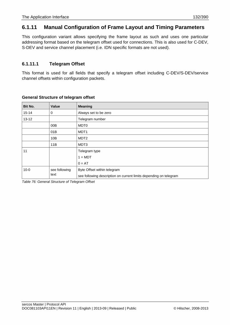
The Application Interface 132/390
sercos Master | Protocol API DOC081103API11EN | Revision 11 | English | 2013-09 | Released | Public © Hilscher, 2008-2013
6.1.11 Manual Configuration of Frame Layout and Timing Parameters
This configuration variant allows specifying the frame layout as such and uses one particular addressing format based on the telegram offset used for connections. This is also used for C-DEV, S-DEV and service channel placement (i.e. IDN specific formats are not used).
6.1.11.1 Telegram Offset
This format is used for all fields that specify a telegram offset including C-DEV/S-DEV/service channel offsets within configuration packets.
General Structure of telegram offset
Bit No. Value Meaning
15-14 0 Always set to be zero
13-12 Telegram number
00B MDT0
01B MDT1
10B MDT2
11B MDT3
11 Telegram type
1 = MDT
0 = AT
10-0 see following text
Byte Offset within telegram
see following description on current limits depending on telegram
Table 76: General Structure of Telegram Offset
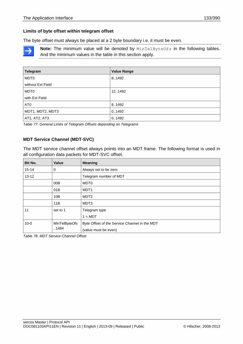
The Application Interface 133/390
sercos Master | Protocol API DOC081103API11EN | Revision 11 | English | 2013-09 | Released | Public © Hilscher, 2008-2013
Limits of byte offset within telegram offset
The byte offset must always be placed at a 2 byte boundary i.e. it must be even.
Note: The minimum value will be denoted by MinTelByteOfs in the following tables. And the minimum values in the table in this section apply.
Telegram Value Range
MDT0
without Ext Field
8..1492
MDT0
with Ext Field
12..1492
AT0 8..1492
MDT1, MDT2, MDT3 0..1492
AT1, AT2, AT3 0..1492
Table 77: General Limits of Telegram Offsets depending on Telegrams
MDT Service Channel (MDT-SVC)
The MDT service channel offset always points into an MDT frame. The following format is used in all configuration data packets for MDT-SVC offset.
Bit No. Value Meaning
15-14 0 Always set to be zero
13-12 Telegram number of MDT
00B MDT0
01B MDT1
10B MDT2
11B MDT3
11 set to 1 Telegram type
1 = MDT
10-0 MinTelByteOfs ..1484
Byte Offset of the Service Channel in the MDT
(value must be even)
Table 78: MDT Service Channel Offset
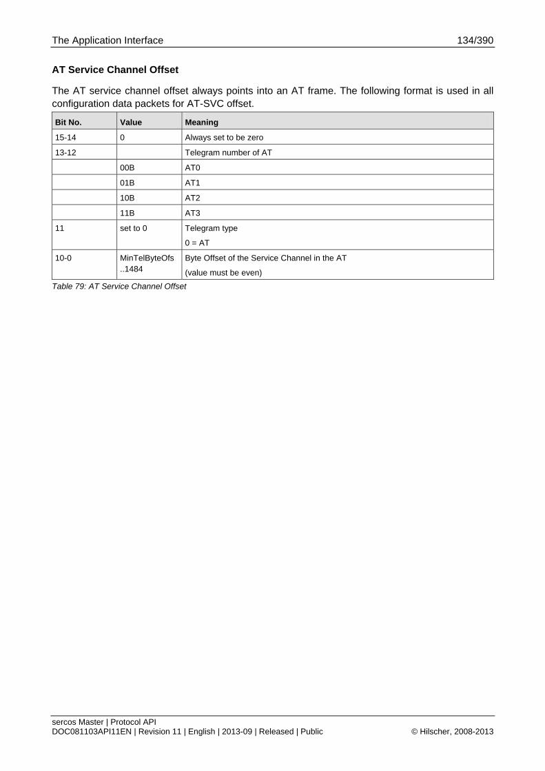
The Application Interface 134/390
sercos Master | Protocol API DOC081103API11EN | Revision 11 | English | 2013-09 | Released | Public © Hilscher, 2008-2013
AT Service Channel Offset
The AT service channel offset always points into an AT frame. The following format is used in all configuration data packets for AT-SVC offset.
Bit No. Value Meaning
15-14 0 Always set to be zero
13-12 Telegram number of AT
00B AT0
01B AT1
10B AT2
11B AT3
11 set to 0 Telegram type
0 = AT
10-0 MinTelByteOfs ..1484
Byte Offset of the Service Channel in the AT
(value must be even)
Table 79: AT Service Channel Offset
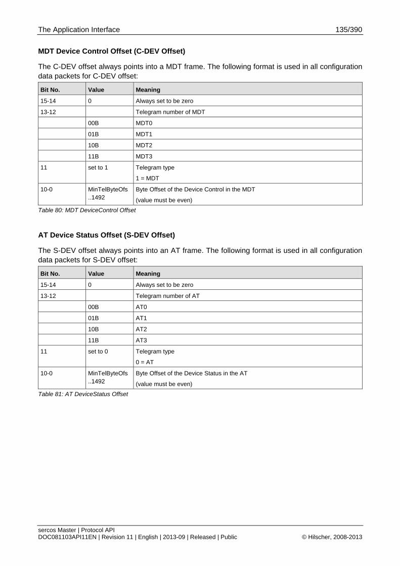
The Application Interface 135/390
sercos Master | Protocol API DOC081103API11EN | Revision 11 | English | 2013-09 | Released | Public © Hilscher, 2008-2013
MDT Device Control Offset (C-DEV Offset)
The C-DEV offset always points into a MDT frame. The following format is used in all configuration data packets for C-DEV offset:
Bit No. Value Meaning
15-14 0 Always set to be zero
13-12 Telegram number of MDT
00B MDT0
01B MDT1
10B MDT2
11B MDT3
11 set to 1 Telegram type
1 = MDT
10-0 MinTelByteOfs ..1492
Byte Offset of the Device Control in the MDT
(value must be even)
Table 80: MDT DeviceControl Offset
AT Device Status Offset (S-DEV Offset)
The S-DEV offset always points into an AT frame. The following format is used in all configuration data packets for S-DEV offset:
Bit No. Value Meaning
15-14 0 Always set to be zero
13-12 Telegram number of AT
00B AT0
01B AT1
10B AT2
11B AT3
11 set to 0 Telegram type
0 = AT
10-0 MinTelByteOfs ..1492
Byte Offset of the Device Status in the AT
(value must be even)
Table 81: AT DeviceStatus Offset
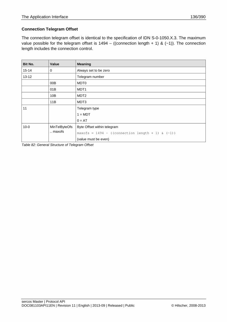
The Application Interface 136/390
sercos Master | Protocol API DOC081103API11EN | Revision 11 | English | 2013-09 | Released | Public © Hilscher, 2008-2013
Connection Telegram Offset
The connection telegram offset is identical to the specification of IDN S-0-1050.X.3. The maximum value possible for the telegram offset is 1494 – ((connection length + 1) & (~1)). The connection length includes the connection control.
Bit No. Value Meaning
15-14 0 Always set to be zero
13-12 Telegram number
00B MDT0
01B MDT1
10B MDT2
11B MDT3
11 Telegram type
1 = MDT
0 = AT
10-0 MinTelByteOfs .. maxofs
Byte Offset within telegram
maxofs = 1494 – ((connection length + 1) & (~1))
(value must be even)
Table 82: General Structure of Telegram Offset
The Application Interface 137/390
sercos Master | Protocol API DOC081103API11EN | Revision 11 | English | 2013-09 | Released | Public © Hilscher, 2008-2013
6.1.11.2 Begin Configuration Transfer Parameters for manual configuration of frame layout and timing parameters
This variant is selected by having bit 2 and 5 cleared in ulStackConfigurationFlags.
The following parameters are used and must be specified:
Communication Cycle Time (tScyc)
Communication Timeout
AT Transmission Starting Time (t1)
NRT transmission start time (t6)
NRT transmission end time (t7)
Command value valid time
Synchronization time (t4)
NRT channel MTU
Process Data Output Size (MDT)
Process Data Input Size (AT)
Minimum CP0 Wait Cycles
For details on these parameters, see 4.2.3 Detailed Description of Master Parameters.
For configuration packets usage and flow diagram, see chapter 6.1.12 Usage and Flow Diagram of manual Configuration of Frame Layout.
The stack configuration flags as needed for this configuration variant are discussed within the following chapter.
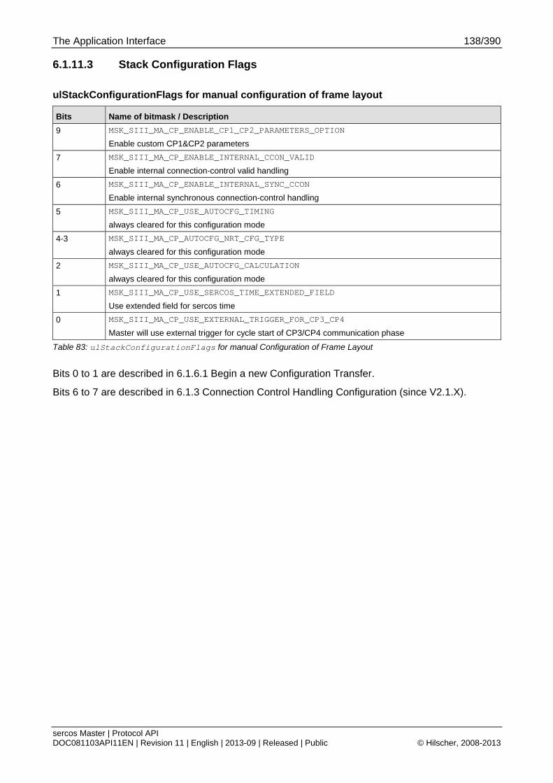
The Application Interface 138/390
sercos Master | Protocol API DOC081103API11EN | Revision 11 | English | 2013-09 | Released | Public © Hilscher, 2008-2013
6.1.11.3 Stack Configuration Flags
ulStackConfigurationFlags for manual configuration of frame layout
Bits Name of bitmask / Description
9 MSK_SIII_MA_CP_ENABLE_CP1_CP2_PARAMETERS_OPTION
Enable custom CP1&CP2 parameters
7 MSK_SIII_MA_CP_ENABLE_INTERNAL_CCON_VALID
Enable internal connection-control valid handling
6 MSK_SIII_MA_CP_ENABLE_INTERNAL_SYNC_CCON
Enable internal synchronous connection-control handling
5 MSK_SIII_MA_CP_USE_AUTOCFG_TIMING
always cleared for this configuration mode
4-3 MSK_SIII_MA_CP_AUTOCFG_NRT_CFG_TYPE
always cleared for this configuration mode
2 MSK_SIII_MA_CP_USE_AUTOCFG_CALCULATION
always cleared for this configuration mode
1 MSK_SIII_MA_CP_USE_SERCOS_TIME_EXTENDED_FIELD
Use extended field for sercos time
0 MSK_SIII_MA_CP_USE_EXTERNAL_TRIGGER_FOR_CP3_CP4
Master will use external trigger for cycle start of CP3/CP4 communication phase
Table 83: ulStackConfigurationFlags for manual Configuration of Frame Layout
Bits 0 to 1 are described in 6.1.6.1 Begin a new Configuration Transfer.
Bits 6 to 7 are described in 6.1.3 Connection Control Handling Configuration (since V2.1.X).
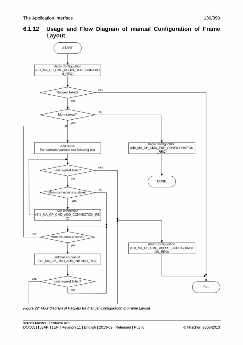
The Application Interface 139/390
sercos Master | Protocol API DOC081103API11EN | Revision 11 | English | 2013-09 | Released | Public © Hilscher, 2008-2013
6.1.12 Usage and Flow Diagram of manual Configuration of Frame Layout
Figure 22: Flow diagram of Packets for manual Configuration of Frame Layout
The Application Interface 140/390
sercos Master | Protocol API DOC081103API11EN | Revision 11 | English | 2013-09 | Released | Public © Hilscher, 2008-2013
6.1.12.1 Usage
The packets have to be used in a specific order. The flow chart above shows the sequence of the packets in which they have to be used.
The packet SIII_MA_CP_CMD_ABORT_CONFIGURATION_REQ has to be used whenever a configuration is not going to be completed due to some error result of the packets in between.
The details on the packet contents are given in the following chapters:
6.1.6 Common Services (all Packet Configuration Variants)
6.1.11 Manual Configuration of Frame Layout and Timing Parameters
6.1.13 Packets used for manual Configuration
Note: After finishing 6.1.6.2 “End a Configuration Transfer Service” when using LFW/SHM API, the 6.1.6.7 “DPM Configuration Service" must be used for configuring the DPM AP task.
Step Add slave
One of the following services has to be used to add a slave to the configuration:
6.1.13.2 Add SCP_FixCFG Slave Data Block Service
6.1.13.3 Add SCP_VarCFG Slave Data Block Service
6.1.13.1 Add Slave Data Block Service
The latter service is only needed for specific cases when a slave does not have consecutively numbered connection instances starting at 0.
The other two services provide common configurations needed for slaves in a single packet access.
Step Add connection
This step is optional since the packet for adding a slave already allows to add connection configuration for the most common case where the connection instance are consecutively used without any gaps (i.e. connection instances 0 to n).
Step Add init command
This step is necessary for SCP_VarCFG slaves since these require parameter writes onto their IDN dictionary.
The Application Interface 141/390
sercos Master | Protocol API DOC081103API11EN | Revision 11 | English | 2013-09 | Released | Public © Hilscher, 2008-2013
6.1.13 Packets used for manual Configuration
6.1.13.1 Add Slave Data Block Service (ManualCfg)
This service adds slave-specific data for one specific slave to the configuration transfer when manual configuration of the frame layout is used.
Prerequisite: The service Begin a new Configuration Transfer has been successfully executed before.
For adding a slave with SCP_FixCFG, the application can use the simple variant described in 6.1.13.2 Add SCP_FixCFG Slave Data Block Service.
For adding a slave with SCP_VarCFG and consecutively numbered connection instances starting from instance number 0, the application can use the simple variant described in.
For configuration packets usage and flow diagram, see chapter 6.1.12 Usage and Flow Diagram of manual Configuration of Frame Layout.
Commonly usable Flags of the ulSlaveConfigurationFlags
Bits Name of bitmask / Description
3 SIII_MA_CP_ADD_SLAVE_REQ_FLAGS_OPTIONAL_SLAVE
Slave is optional
1 SIII_MA_CP_ADD_SLAVE_REQ_FLAGS_ENABLE_HOTPLUG
Hot plugging enabled
Table 84: Meaning of the ulSlaveConfigurationFlags
For a full list of all flags and a detailed description of the parameters, see 6.1.4.1 Slave Configuration Flags.
Packet Structure Reference
typedef struct SIII_MA_CP_ADD_SLAVE_REQ_DATA_Ttag { TLR_UINT16 usSlaveAddress; TLR_UINT16 usMDTSvChOffset; TLR_UINT16 usATSvChOffset; TLR_UINT16 usDevCtrlOffset; TLR_UINT16 usDevStatOffset; TLR_UINT32 ulSlaveConfigurationFlags; } SIII_MA_CP_ADD_SLAVE_REQ_DATA_T; typedef struct SIII_MA_CP_ADD_SLAVE_REQ_Ttag { TLR_PACKET_HEADER_T tHead; SIII_MA_CP_ADD_SLAVE_REQ_DATA_T tData; } SIII_MA_CP_ADD_SLAVE_REQ_T;
The Application Interface 142/390
sercos Master | Protocol API DOC081103API11EN | Revision 11 | English | 2013-09 | Released | Public © Hilscher, 2008-2013
Packet Description
Structure SIII_MA_CP_ADD_SLAVE_REQ_T Type: Request
Variable Type Value / Range Description
tHead - Structure TLR_PACKET_HEADER_T
ulDest UINT32 Destination Queue-Handle
ulSrc UINT32 Source Queue-Handle
ulDestId UINT32 Destination End Point Identifier, specifying the final receiver of the packet within the Destination Process. Set to 0 for the Initialization Packet
ulSrcId UINT32 Source End Point Identifier, specifying the origin of the packet inside the Source Process
ulLen UINT32 14 Packet Data Length in bytes
ulId UINT32 0 ... 232-1 Packet Identification as unique number generated by the Source Process of the Packet
ulSta UINT32 See section Status/Error Codes Overview
ulCmd UINT32 0x4826 SIII_MA_CP_CMD_ADD_SLAVE_REQ - Command
ulExt UINT32 0 Extension, reserved
ulRout UINT32 x Routing, do not touch
tData - Structure SIII_MA_CP_ADD_SLAVE_REQ_DATA_T
usSlaveAddress UINT16 1.. 511 Slave Address (representing the SERCOSIII-Device Address)
usMDTSvChOffset
UINT16 See 6.1.11.1 Telegram Offset for details on MDT-SVC offset
usATSvChOffset UINT16 See 6.1.11.1 Telegram Offset for details on AT-SVC offset
usDevCtrlOffset UINT16 See 6.1.11.1 Telegram Offset for details on C-DEV offset
usDevStatOffset UINT16 See 6.1.11.1 Telegram Offset for details on S-DEV offset
ulSlaveConfigurationFlags
UINT32 Slave configuration flags
See Table 84: Meaning of the ulSlaveConfigurationFlags for common flags
Table 85: SIII_MA_CP_CMD_ADD_SLAVE_REQ – Add Slave Data Block Request

The Application Interface 143/390
sercos Master | Protocol API DOC081103API11EN | Revision 11 | English | 2013-09 | Released | Public © Hilscher, 2008-2013
Packet Structure Reference
typedef struct SIII_MA_CP_ADD_SLAVE_CNF_Ttag { TLR_PACKET_HEADER_T tHead; } SIII_MA_CP_ADD_SLAVE_CNF_T;
Packet Description
Structure SIII_MA_CP_ADD_SLAVE_CNF_T Type: Confirmation
Variable Type Value / Range Description
tHead - Structure TLR_PACKET_HEADER_T
ulDest UINT32 Destination queue handle, unchanged
ulSrc UINT32 Source queue handle, unchanged
ulDestId UINT32 Destination End Point Identifier, specifying the final receiver of the packet within the Destination Process. Set to 0 for the Initialization Packet
ulSrcId UINT32 Source End Point Identifier, specifying the origin of the packet inside the Source Process
ulLen UINT32 0 Packet Data Length in bytes
ulId UINT32 0 ... 232-1 Packet Identification as unique number generated by the Source Process of the Packet
ulSta UINT32 See section Status/Error Codes Overview
ulCmd UINT32 0x4827 SIII_MA_CP_CMD_ADD_SLAVE_CNF - Command
ulExt UINT32 0 Extension not in use, set to zero for compatibility reasons
ulRout UINT32 x Routing, do not touch
Table 86: SIII_MA_CP_CMD_ADD_SLAVE_CNF – Add Slave Data Block Confirmation
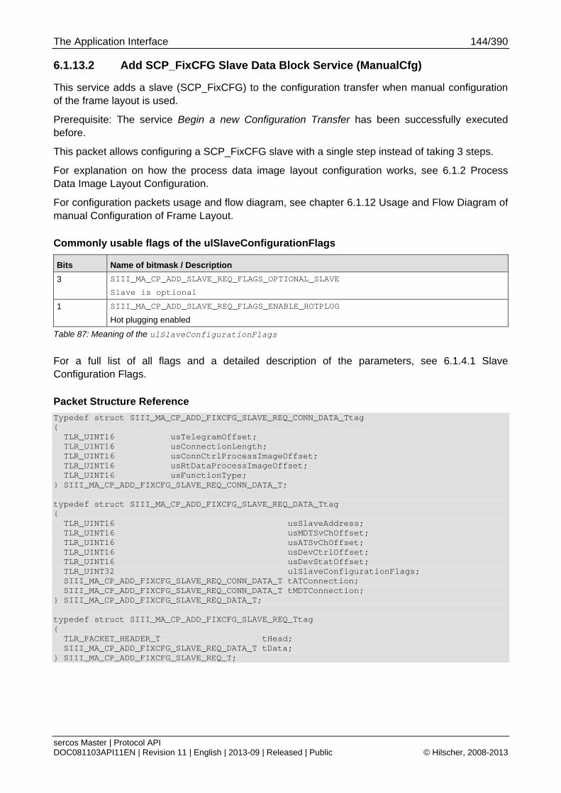
The Application Interface 144/390
sercos Master | Protocol API DOC081103API11EN | Revision 11 | English | 2013-09 | Released | Public © Hilscher, 2008-2013
6.1.13.2 Add SCP_FixCFG Slave Data Block Service (ManualCfg)
This service adds a slave (SCP_FixCFG) to the configuration transfer when manual configuration of the frame layout is used.
Prerequisite: The service Begin a new Configuration Transfer has been successfully executed before.
This packet allows configuring a SCP_FixCFG slave with a single step instead of taking 3 steps.
For explanation on how the process data image layout configuration works, see 6.1.2 Process Data Image Layout Configuration.
For configuration packets usage and flow diagram, see chapter 6.1.12 Usage and Flow Diagram of manual Configuration of Frame Layout.
Commonly usable flags of the ulSlaveConfigurationFlags
Bits Name of bitmask / Description
3 SIII_MA_CP_ADD_SLAVE_REQ_FLAGS_OPTIONAL_SLAVE
Slave is optional
1 SIII_MA_CP_ADD_SLAVE_REQ_FLAGS_ENABLE_HOTPLUG
Hot plugging enabled
Table 87: Meaning of the ulSlaveConfigurationFlags
For a full list of all flags and a detailed description of the parameters, see 6.1.4.1 Slave Configuration Flags.
Packet Structure Reference
Typedef struct SIII_MA_CP_ADD_FIXCFG_SLAVE_REQ_CONN_DATA_Ttag { TLR_UINT16 usTelegramOffset; TLR_UINT16 usConnectionLength; TLR_UINT16 usConnCtrlProcessImageOffset; TLR_UINT16 usRtDataProcessImageOffset; TLR_UINT16 usFunctionType; } SIII_MA_CP_ADD_FIXCFG_SLAVE_REQ_CONN_DATA_T; typedef struct SIII_MA_CP_ADD_FIXCFG_SLAVE_REQ_DATA_Ttag { TLR_UINT16 usSlaveAddress; TLR_UINT16 usMDTSvChOffset; TLR_UINT16 usATSvChOffset; TLR_UINT16 usDevCtrlOffset; TLR_UINT16 usDevStatOffset; TLR_UINT32 ulSlaveConfigurationFlags; SIII_MA_CP_ADD_FIXCFG_SLAVE_REQ_CONN_DATA_T tATConnection; SIII_MA_CP_ADD_FIXCFG_SLAVE_REQ_CONN_DATA_T tMDTConnection; } SIII_MA_CP_ADD_FIXCFG_SLAVE_REQ_DATA_T; typedef struct SIII_MA_CP_ADD_FIXCFG_SLAVE_REQ_Ttag { TLR_PACKET_HEADER_T tHead; SIII_MA_CP_ADD_FIXCFG_SLAVE_REQ_DATA_T tData; } SIII_MA_CP_ADD_FIXCFG_SLAVE_REQ_T;

The Application Interface 145/390
sercos Master | Protocol API DOC081103API11EN | Revision 11 | English | 2013-09 | Released | Public © Hilscher, 2008-2013
Packet Description
Structure SIII_MA_CP_ADD_FIXCFG_SLAVE_REQ_T Type: Request
Variable Type Value / Range Description
tHead - Structure TLR_PACKET_HEADER_T
ulDest UINT32 Destination Queue-Handle
ulSrc UINT32 Source Queue-Handle
ulDestId UINT32 Destination End Point Identifier, specifying the final receiver of the packet within the Destination Process. Set to 0 for the Initialization Packet
ulSrcId UINT32 Source End Point Identifier, specifying the origin of the packet inside the Source Process
ulLen UINT32 22 Packet Data Length in bytes
ulId UINT32 0 ... 232-1 Packet Identification as unique number generated by the Source Process of the Packet
ulSta UINT32 See section Status/Error Codes Overview
ulCmd UINT32 0x4876 SIII_MA_CP_CMD_ADD_FIXCFG_SLAVE_REQ - Command
ulExt UINT32 0 Extension, reserved
ulRout UINT32 x Routing, do not touch
tData - Structure SIII_MA_CP_ADD_FIXCFG_SLAVE_REQ_DATA_T
usSlaveAddress UINT16 1.. 511 Slave Address (representing the SERCOSIII-Device Address)
usMDTSvChOffset
UINT16 See 6.1.11.1 Telegram Offset for details on MDT-SVC offset
usATSvChOffset UINT16 See 6.1.11.1 Telegram Offset for details on AT-SVC offset
usDevCtrlOffset UINT16 See 6.1.11.1 Telegram Offset for details on C-DEV offset
usDevStatOffset UINT16 See 6.1.11.1 Telegram Offset for details on S-DEV offset
ulSlaveConfigurationFlags
UINT32 Slave configuration flags
See Table 84: Meaning of the ulSlaveConfigurationFlags for common flags
tATConnection SIII_MA_CP_ADD_FIXCFG_SLAVE_REQ_CONN_DATA_T
Configuration parameters for AT connection
For details, see below
tMDTConnection SIII_MA_CP_ADD_FIXCFG_SLAVE_REQ_CONN_DATA_T
Configuration parameters for MDT connection
For details, see below
Table 88: SIII_MA_CP_CMD_ADD_FIXCFG_SLAVE_REQ – Add SCP_FixCFG Slave Data Block Request
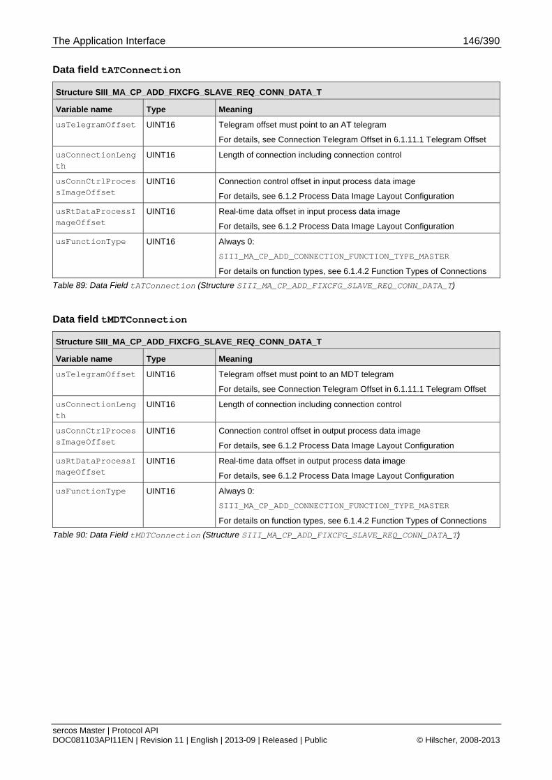
The Application Interface 146/390
sercos Master | Protocol API DOC081103API11EN | Revision 11 | English | 2013-09 | Released | Public © Hilscher, 2008-2013
Data field tATConnection
Structure SIII_MA_CP_ADD_FIXCFG_SLAVE_REQ_CONN_DATA_T
Variable name Type Meaning
usTelegramOffset UINT16 Telegram offset must point to an AT telegram
For details, see Connection Telegram Offset in 6.1.11.1 Telegram Offset
usConnectionLength
UINT16 Length of connection including connection control
usConnCtrlProcessImageOffset
UINT16 Connection control offset in input process data image
For details, see 6.1.2 Process Data Image Layout Configuration
usRtDataProcessImageOffset
UINT16 Real-time data offset in input process data image
For details, see 6.1.2 Process Data Image Layout Configuration
usFunctionType UINT16 Always 0:
SIII_MA_CP_ADD_CONNECTION_FUNCTION_TYPE_MASTER
For details on function types, see 6.1.4.2 Function Types of Connections
Table 89: Data Field tATConnection (Structure SIII_MA_CP_ADD_FIXCFG_SLAVE_REQ_CONN_DATA_T)
Data field tMDTConnection
Structure SIII_MA_CP_ADD_FIXCFG_SLAVE_REQ_CONN_DATA_T
Variable name Type Meaning
usTelegramOffset UINT16 Telegram offset must point to an MDT telegram
For details, see Connection Telegram Offset in 6.1.11.1 Telegram Offset
usConnectionLength
UINT16 Length of connection including connection control
usConnCtrlProcessImageOffset
UINT16 Connection control offset in output process data image
For details, see 6.1.2 Process Data Image Layout Configuration
usRtDataProcessImageOffset
UINT16 Real-time data offset in output process data image
For details, see 6.1.2 Process Data Image Layout Configuration
usFunctionType UINT16 Always 0:
SIII_MA_CP_ADD_CONNECTION_FUNCTION_TYPE_MASTER
For details on function types, see 6.1.4.2 Function Types of Connections
Table 90: Data Field tMDTConnection (Structure SIII_MA_CP_ADD_FIXCFG_SLAVE_REQ_CONN_DATA_T)

The Application Interface 147/390
sercos Master | Protocol API DOC081103API11EN | Revision 11 | English | 2013-09 | Released | Public © Hilscher, 2008-2013
Packet Structure Reference
typedef struct SIII_MA_CP_ADD_FIXCFG_SLAVE_CNF_Ttag { TLR_PACKET_HEADER_T tHead; } SIII_MA_CP_ADD_FIXCFG_SLAVE_CNF_T;
Packet Description
Structure SIII_MA_CP_ADD_FIXCFG_SLAVE_CNF_T Type: Confirmation
Variable Type Value / Range Description
tHead - Structure TLR_PACKET_HEADER_T
ulDest UINT32 Destination queue handle, unchanged
ulSrc UINT32 Source queue handle, unchanged
ulDestId UINT32 Destination End Point Identifier, specifying the final receiver of the packet within the Destination Process. Set to 0 for the Initialization Packet
ulSrcId UINT32 Source End Point Identifier, specifying the origin of the packet inside the Source Process
ulLen UINT32 0 Packet Data Length in bytes
ulId UINT32 0 ... 232-1 Packet Identification as unique number generated by the Source Process of the Packet
ulSta UINT32 See section Status/Error Codes Overview
ulCmd UINT32 0x4877 SIII_MA_CP_CMD_ADD_FIXCFG_SLAVE_CNF - Command
ulExt UINT32 0 Extension not in use, set to zero for compatibility reasons
ulRout UINT32 x Routing, do not touch
Table 91: SIII_MA_CP_CMD_ADD_FIXCFG_SLAVE_CNF – Add SCP_FIXCFG Slave Data Block Confirmation

The Application Interface 148/390
sercos Master | Protocol API DOC081103API11EN | Revision 11 | English | 2013-09 | Released | Public © Hilscher, 2008-2013
6.1.13.3 Add SCP_VarCFG Slave Data Block Service (ManualCfg)
This service adds a slave (SCP_VarCFG) to the configuration transfer when manual configuration of the frame layout is used.
Prerequisite: The service Begin a new Configuration Transfer has been successfully executed before.
This packet allows configuring a SCP_VarCFG slave with a single step instead of taking multiple steps when the connection instances are numbered consecutively starting from instance 0.
For explanation on how the process data image layout configuration works, see 6.1.2 Process Data Image Layout Configuration.
For configuration packets usage and flow diagram, see chapter 6.1.12 Usage and Flow Diagram of manual Configuration of Frame Layout.
Commonly usable flags of the ulSlaveConfigurationFlags
Bits Name of bitmask / Description
3 SIII_MA_CP_ADD_SLAVE_REQ_FLAGS_OPTIONAL_SLAVE
Slave is optional
1 SIII_MA_CP_ADD_SLAVE_REQ_FLAGS_ENABLE_HOTPLUG
Hot plugging enabled
Table 92: Meaning of the ulSlaveConfigurationFlags
For a full list of all flags and a detailed description of the parameters, see 6.1.4.1 Slave Configuration Flags.
Packet Structure Reference
Typedef struct SIII_MA_CP_ADD_VARCFG_SLAVE_REQ_CONN_DATA_Ttag { TLR_UINT16 usTelegramOffset; TLR_UINT16 usConnectionLength; TLR_UINT16 usConnCtrlProcessImageOffset; TLR_UINT16 usRtDataProcessImageOffset; TLR_UINT16 usFunctionType; } SIII_MA_CP_ADD_VARCFG_SLAVE_REQ_CONN_DATA_T; typedef struct SIII_MA_CP_ADD_VARCFG_SLAVE_REQ_DATA_Ttag { TLR_UINT16 usSlaveAddress; TLR_UINT16 usMDTSvChOffset; TLR_UINT16 usATSvChOffset; TLR_UINT16 usDevCtrlOffset; TLR_UINT16 usDevStatOffset; TLR_UINT32 ulSlaveConfigurationFlags; SIII_MA_CP_ADD_VARCFG_SLAVE_REQ_CONN_DATA_T atConnections[256]; } SIII_MA_CP_ADD_VARCFG_SLAVE_REQ_DATA_T; typedef struct SIII_MA_CP_ADD_VARCFG_SLAVE_REQ_Ttag { TLR_PACKET_HEADER_T tHead; SIII_MA_CP_ADD_VARCFG_SLAVE_REQ_DATA_T tData; } SIII_MA_CP_ADD_VARCFG_SLAVE_REQ_T;
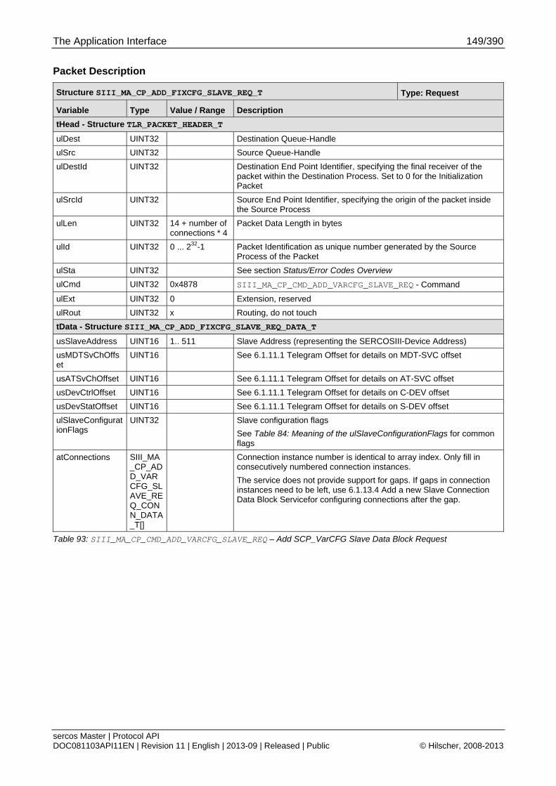
The Application Interface 149/390
sercos Master | Protocol API DOC081103API11EN | Revision 11 | English | 2013-09 | Released | Public © Hilscher, 2008-2013
Packet Description
Structure SIII_MA_CP_ADD_FIXCFG_SLAVE_REQ_T Type: Request
Variable Type Value / Range Description
tHead - Structure TLR_PACKET_HEADER_T
ulDest UINT32 Destination Queue-Handle
ulSrc UINT32 Source Queue-Handle
ulDestId UINT32 Destination End Point Identifier, specifying the final receiver of the packet within the Destination Process. Set to 0 for the Initialization Packet
ulSrcId UINT32 Source End Point Identifier, specifying the origin of the packet inside the Source Process
ulLen UINT32 14 + number of connections * 4
Packet Data Length in bytes
ulId UINT32 0 ... 232-1 Packet Identification as unique number generated by the Source Process of the Packet
ulSta UINT32 See section Status/Error Codes Overview
ulCmd UINT32 0x4878 SIII_MA_CP_CMD_ADD_VARCFG_SLAVE_REQ - Command
ulExt UINT32 0 Extension, reserved
ulRout UINT32 x Routing, do not touch
tData - Structure SIII_MA_CP_ADD_FIXCFG_SLAVE_REQ_DATA_T
usSlaveAddress UINT16 1.. 511 Slave Address (representing the SERCOSIII-Device Address)
usMDTSvChOffset
UINT16 See 6.1.11.1 Telegram Offset for details on MDT-SVC offset
usATSvChOffset UINT16 See 6.1.11.1 Telegram Offset for details on AT-SVC offset
usDevCtrlOffset UINT16 See 6.1.11.1 Telegram Offset for details on C-DEV offset
usDevStatOffset UINT16 See 6.1.11.1 Telegram Offset for details on S-DEV offset
ulSlaveConfigurationFlags
UINT32 Slave configuration flags
See Table 84: Meaning of the ulSlaveConfigurationFlags for common flags
atConnections SIII_MA_CP_ADD_VARCFG_SLAVE_REQ_CONN_DATA_T[]
Connection instance number is identical to array index. Only fill in consecutively numbered connection instances.
The service does not provide support for gaps. If gaps in connection instances need to be left, use 6.1.13.4 Add a new Slave Connection Data Block Servicefor configuring connections after the gap.
Table 93: SIII_MA_CP_CMD_ADD_VARCFG_SLAVE_REQ – Add SCP_VarCFG Slave Data Block Request
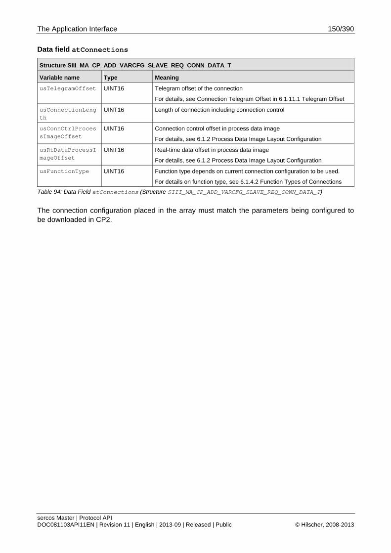
The Application Interface 150/390
sercos Master | Protocol API DOC081103API11EN | Revision 11 | English | 2013-09 | Released | Public © Hilscher, 2008-2013
Data field atConnections
Structure SIII_MA_CP_ADD_VARCFG_SLAVE_REQ_CONN_DATA_T
Variable name Type Meaning
usTelegramOffset UINT16 Telegram offset of the connection
For details, see Connection Telegram Offset in 6.1.11.1 Telegram Offset
usConnectionLength
UINT16 Length of connection including connection control
usConnCtrlProcessImageOffset
UINT16 Connection control offset in process data image
For details, see 6.1.2 Process Data Image Layout Configuration
usRtDataProcessImageOffset
UINT16 Real-time data offset in process data image
For details, see 6.1.2 Process Data Image Layout Configuration
usFunctionType UINT16 Function type depends on current connection configuration to be used.
For details on function type, see 6.1.4.2 Function Types of Connections
Table 94: Data Field atConnections (Structure SIII_MA_CP_ADD_VARCFG_SLAVE_REQ_CONN_DATA_T)
The connection configuration placed in the array must match the parameters being configured to be downloaded in CP2.

The Application Interface 151/390
sercos Master | Protocol API DOC081103API11EN | Revision 11 | English | 2013-09 | Released | Public © Hilscher, 2008-2013
Packet Structure Reference
typedef struct SIII_MA_CP_ADD_VARCFG_SLAVE_CNF_Ttag { TLR_PACKET_HEADER_T tHead; } SIII_MA_CP_ADD_VARCFG_SLAVE_CNF_T;
Packet Description
Structure SIII_MA_CP_ADD_VARCFG_SLAVE_CNF_T Type: Confirmation
Variable Type Value / Range Description
tHead - Structure TLR_PACKET_HEADER_T
ulDest UINT32 Destination queue handle, unchanged
ulSrc UINT32 Source queue handle, unchanged
ulDestId UINT32 Destination End Point Identifier, specifying the final receiver of the packet within the Destination Process. Set to 0 for the Initialization Packet
ulSrcId UINT32 Source End Point Identifier, specifying the origin of the packet inside the Source Process
ulLen UINT32 0 Packet Data Length in bytes
ulId UINT32 0 ... 232-1 Packet Identification as unique number generated by the Source Process of the Packet
ulSta UINT32 See section Status/Error Codes Overview
ulCmd UINT32 0x4879 SIII_MA_CP_CMD_ADD_VARCFG_SLAVE_CNF - Command
ulExt UINT32 0 Extension not in use, set to zero for compatibility reasons
ulRout UINT32 x Routing, do not touch
Table 95: SIII_MA_CP_CMD_ADD_VARCFG_SLAVE_CNF – Add SCP_VarCFG Slave Data Block Confirmation
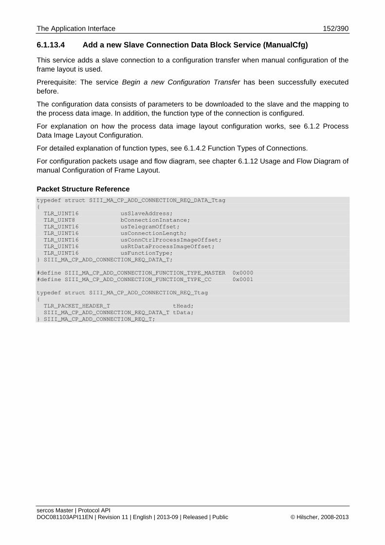
The Application Interface 152/390
sercos Master | Protocol API DOC081103API11EN | Revision 11 | English | 2013-09 | Released | Public © Hilscher, 2008-2013
6.1.13.4 Add a new Slave Connection Data Block Service (ManualCfg)
This service adds a slave connection to a configuration transfer when manual configuration of the frame layout is used.
Prerequisite: The service Begin a new Configuration Transfer has been successfully executed before.
The configuration data consists of parameters to be downloaded to the slave and the mapping to the process data image. In addition, the function type of the connection is configured.
For explanation on how the process data image layout configuration works, see 6.1.2 Process Data Image Layout Configuration.
For detailed explanation of function types, see 6.1.4.2 Function Types of Connections.
For configuration packets usage and flow diagram, see chapter 6.1.12 Usage and Flow Diagram of manual Configuration of Frame Layout.
Packet Structure Reference
typedef struct SIII_MA_CP_ADD_CONNECTION_REQ_DATA_Ttag { TLR_UINT16 usSlaveAddress; TLR_UINT8 bConnectionInstance; TLR_UINT16 usTelegramOffset; TLR_UINT16 usConnectionLength; TLR_UINT16 usConnCtrlProcessImageOffset; TLR_UINT16 usRtDataProcessImageOffset; TLR_UINT16 usFunctionType; } SIII_MA_CP_ADD_CONNECTION_REQ_DATA_T; #define SIII_MA_CP_ADD_CONNECTION_FUNCTION_TYPE_MASTER 0x0000 #define SIII_MA_CP_ADD_CONNECTION_FUNCTION_TYPE_CC 0x0001 typedef struct SIII_MA_CP_ADD_CONNECTION_REQ_Ttag { TLR_PACKET_HEADER_T tHead; SIII_MA_CP_ADD_CONNECTION_REQ_DATA_T tData; } SIII_MA_CP_ADD_CONNECTION_REQ_T;
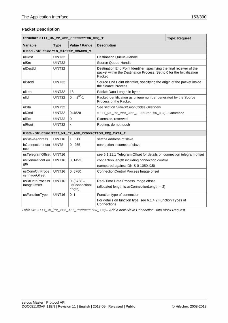
The Application Interface 153/390
sercos Master | Protocol API DOC081103API11EN | Revision 11 | English | 2013-09 | Released | Public © Hilscher, 2008-2013
Packet Description
Structure SIII_MA_CP_ADD_CONNECTION_REQ_T Type: Request
Variable Type Value / Range Description
tHead - Structure TLR_PACKET_HEADER_T
ulDest UINT32 Destination Queue-Handle
ulSrc UINT32 Source Queue-Handle
ulDestId UINT32 Destination End Point Identifier, specifying the final receiver of the packet within the Destination Process. Set to 0 for the Initialization Packet
ulSrcId UINT32 Source End Point Identifier, specifying the origin of the packet inside the Source Process
ulLen UINT32 13 Packet Data Length in bytes
ulId UINT32 0 ... 232-1 Packet Identification as unique number generated by the Source Process of the Packet
ulSta UINT32 See section Status/Error Codes Overview
ulCmd UINT32 0x4828 SIII_MA_CP_CMD_ADD_CONNECTION_REQ - Command
ulExt UINT32 0 Extension, reserved
ulRout UINT32 x Routing, do not touch
tData - Structure SIII_MA_CP_ADD_CONNECTION_REQ_DATA_T
usSlaveAddress UINT16 1.. 511 sercos address of slave
bConnectionInstance
UINT8 0.. 255 connection instance of slave
usTelegramOffset UINT16 see 6.1.11.1 Telegram Offset for details on connection telegram offset
usConnectionLength
UINT16 0..1492 connection length including connection control
(compared against IDN S-0-1050.X.5)
usConnCtrlProcessImageOffset
UINT16 0..5760 ConnectionControl Process Image offset
usRtDataProcessImageOffset
UINT16 0..(5758 – usConnectionLength)
Real-Time Data Process Image offset
(allocated length is usConnectionLength – 2)
usFunctionType UINT16 0, 1 Function type of connection
For details on function type, see 6.1.4.2 Function Types of Connections
Table 96: SIII_MA_CP_CMD_ADD_CONNECTION_REQ – Add a new Slave Connection Data Block Request

The Application Interface 154/390
sercos Master | Protocol API DOC081103API11EN | Revision 11 | English | 2013-09 | Released | Public © Hilscher, 2008-2013
Packet Structure Reference
typedef struct SIII_MA_CP_ADD_CONNECTION_CNF_Ttag { TLR_PACKET_HEADER_T tHead; } SIII_MA_CP_ADD_CONNECTION_CNF_T;
Packet Description
Structure SIII_MA_CP_ADD_CONNECTION_CNF_T Type: Confirmation
Variable Type Value / Range Description
tHead - Structure TLR_PACKET_HEADER_T
ulDest UINT32 Destination queue handle, unchanged
ulSrc UINT32 Source queue handle, unchanged
ulDestId UINT32 Destination End Point Identifier, specifying the final receiver of the packet within the Destination Process. Set to 0 for the Initialization Packet
ulSrcId UINT32 Source End Point Identifier, specifying the origin of the packet inside the Source Process
ulLen UINT32 0 Packet Data Length in bytes
ulId UINT32 0 ... 232-1 Packet Identification as unique number generated by the Source Process of the Packet
ulSta UINT32 See section Status/Error Codes Overview
ulCmd UINT32 0x4829 SIII_MA_CP_CMD_ADD_CONNECTION_CNF - Command
ulExt UINT32 0 Extension not in use, set to zero for compatibility reasons
ulRout UINT32 x Routing, do not touch
Table 97: SIII_MA_CP_CMD_ADD_CONNECTION_CNF – Add a new Slave Connection Data Block Confirmation
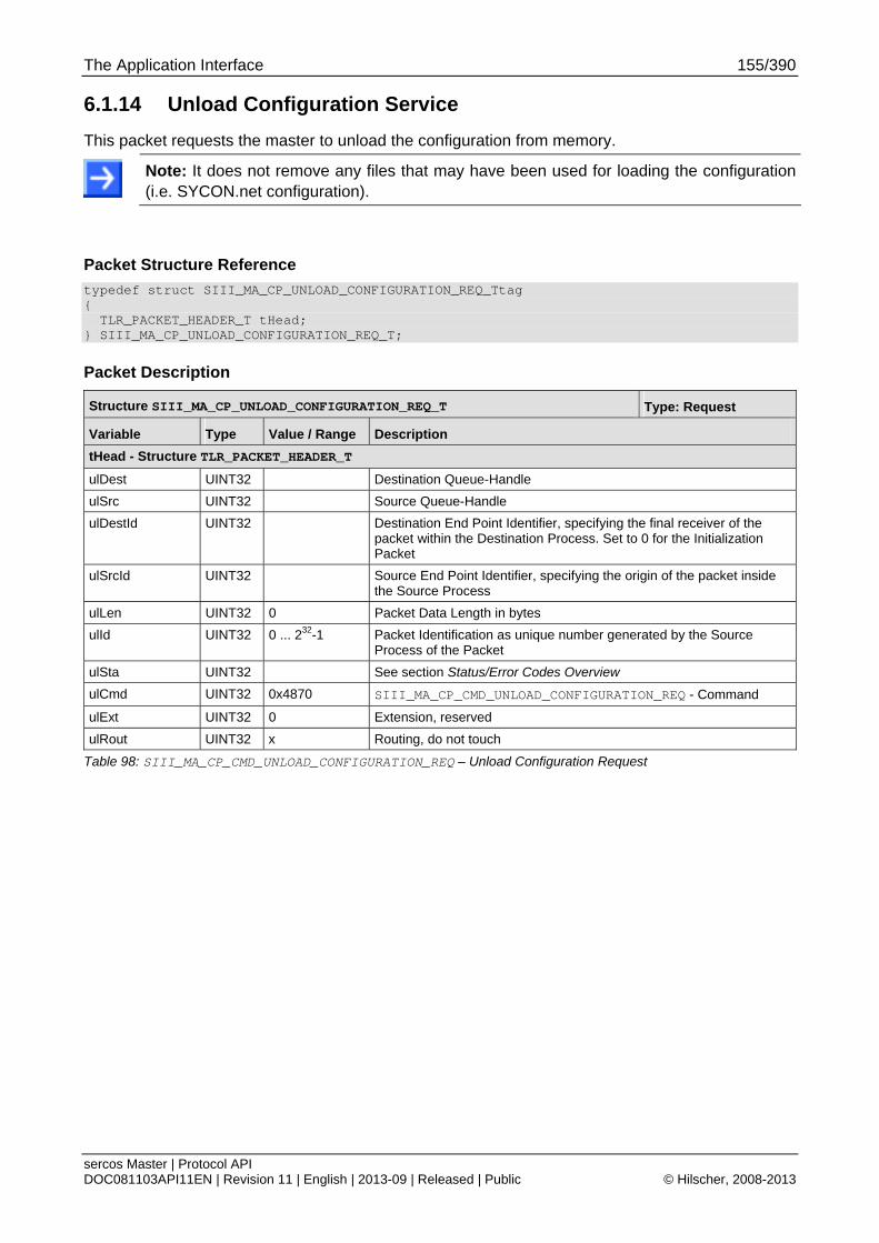
The Application Interface 155/390
sercos Master | Protocol API DOC081103API11EN | Revision 11 | English | 2013-09 | Released | Public © Hilscher, 2008-2013
6.1.14 Unload Configuration Service
This packet requests the master to unload the configuration from memory.
Note: It does not remove any files that may have been used for loading the configuration (i.e. SYCON.net configuration).
Packet Structure Reference
typedef struct SIII_MA_CP_UNLOAD_CONFIGURATION_REQ_Ttag { TLR_PACKET_HEADER_T tHead; } SIII_MA_CP_UNLOAD_CONFIGURATION_REQ_T;
Packet Description
Structure SIII_MA_CP_UNLOAD_CONFIGURATION_REQ_T Type: Request
Variable Type Value / Range Description
tHead - Structure TLR_PACKET_HEADER_T
ulDest UINT32 Destination Queue-Handle
ulSrc UINT32 Source Queue-Handle
ulDestId UINT32 Destination End Point Identifier, specifying the final receiver of the packet within the Destination Process. Set to 0 for the Initialization Packet
ulSrcId UINT32 Source End Point Identifier, specifying the origin of the packet inside the Source Process
ulLen UINT32 0 Packet Data Length in bytes
ulId UINT32 0 ... 232-1 Packet Identification as unique number generated by the Source Process of the Packet
ulSta UINT32 See section Status/Error Codes Overview
ulCmd UINT32 0x4870 SIII_MA_CP_CMD_UNLOAD_CONFIGURATION_REQ - Command
ulExt UINT32 0 Extension, reserved
ulRout UINT32 x Routing, do not touch
Table 98: SIII_MA_CP_CMD_UNLOAD_CONFIGURATION_REQ – Unload Configuration Request

The Application Interface 156/390
sercos Master | Protocol API DOC081103API11EN | Revision 11 | English | 2013-09 | Released | Public © Hilscher, 2008-2013
Packet Structure Reference
typedef struct SIII_MA_CP_UNLOAD_CONFIGURATION_CNF_Ttag { TLR_PACKET_HEADER_T tHead; } SIII_MA_CP_UNLOAD_CONFIGURATION_CNF_T;
Packet Description
Structure SIII_MA_CP_UNLOAD_CONFIGURATION_CNF_T Type: Confirmation
Variable Type Value / Range Description
tHead - Structure TLR_PACKET_HEADER_T
ulDest UINT32 Destination queue handle, unchanged
ulSrc UINT32 Source queue handle, unchanged
ulDestId UINT32 Destination End Point Identifier, specifying the final receiver of the packet within the Destination Process. Set to 0 for the Initialization Packet
ulSrcId UINT32 Source End Point Identifier, specifying the origin of the packet inside the Source Process
ulLen UINT32 0 Packet Data Length in bytes
ulId UINT32 0 ... 232-1 Packet Identification as unique number generated by the Source Process of the Packet
ulSta UINT32 See section Status/Error Codes Overview
ulCmd UINT32 0x4871 SIII_MA_CP_CMD_UNLOAD_CONFIGURATION_CNF - Command
ulExt UINT32 0 Extension not in use, set to zero for compatibility reasons
ulRout UINT32 x Routing, do not touch
Table 99: SIII_MA_CP_CMD_UNLOAD_CONFIGURATION_CNF – Unload Configuration Confirmation
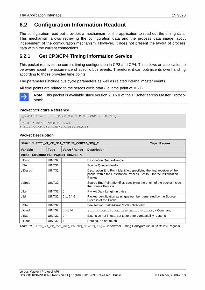
The Application Interface 157/390
sercos Master | Protocol API DOC081103API11EN | Revision 11 | English | 2013-09 | Released | Public © Hilscher, 2008-2013
6.2 Configuration Information Readout
The configuration read out provides a mechanism for the application to read out the timing data. This mechanism allows retrieving the configuration data and the process data image layout independent of the configuration mechanism. However, it does not present the layout of process data within the current connections.
6.2.1 Get CP3/CP4 Timing Information Service
This packet retrieves the current timing configuration in CP3 and CP4. This allows an application to be aware about the occurrence of specific bus events. Therefore, it can optimize its own handling according to those provided time points.
The parameters include bus cycle parameters as well as related internal master events.
All time points are related to the sercos cycle start (i.e. time point of MST).
Note: This packet is available since version 2.0.6.0 of the Hilscher sercos Master Protocol stack.
Packet Structure Reference
typedef struct SIII_MA_CP_GET_TIMING_CONFIG_REQ_Ttag { TLR_PACKET_HEADER_T tHead; } SIII_MA_CP_GET_TIMING_CONFIG_REQ_T;
Packet Description
Structure SIII_MA_CP_GET_TIMING_CONFIG_REQ_T Type: Request
Variable Type Value / Range Description
tHead - Structure TLR_PACKET_HEADER_T
ulDest UINT32 Destination Queue-Handle
ulSrc UINT32 Source Queue-Handle
ulDestId UINT32 Destination End Point Identifier, specifying the final receiver of the packet within the Destination Process. Set to 0 for the Initialization Packet
ulSrcId UINT32 Source End Point Identifier, specifying the origin of the packet inside the Source Process
ulLen UINT32 0 Packet Data Length in bytes
ulId UINT32 0 ... 232-1 Packet Identification as unique number generated by the Source Process of the Packet
ulSta UINT32 See section Status/Error Codes Overview
ulCmd UINT32 0x4874 SIII_MA_CP_CMD_GET_TIMING_CONFIG_REQ - Command
ulExt UINT32 0 Extension not in use, set to zero for compatibility reasons
ulRout UINT32 x Routing, do not touch
Table 100: SIII_MA_CP_CMD_GET_TIMING_CONFIG_REQ – Get current Timing Configuration in CP3/CP4 Request
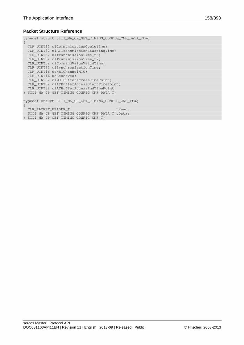
The Application Interface 158/390
sercos Master | Protocol API DOC081103API11EN | Revision 11 | English | 2013-09 | Released | Public © Hilscher, 2008-2013
Packet Structure Reference
typedef struct SIII_MA_CP_GET_TIMING_CONFIG_CNF_DATA_Ttag { TLR_UINT32 ulCommunicationCycleTime; TLR_UINT32 ulATTransmissionStartingTime; TLR_UINT32 ulTransmissionTime_t6; TLR_UINT32 ulTransmissionTime_t7; TLR_UINT32 ulCommandValueValidTime; TLR_UINT32 ulSynchronizationTime; TLR_UINT16 usNRTChannelMTU; TLR_UINT16 usReserved; TLR_UINT32 ulMDTBufferAccessTimePoint; TLR_UINT32 ulATBufferAccessStartTimePoint; TLR_UINT32 ulATBufferAccessEndTimePoint; } SIII_MA_CP_GET_TIMING_CONFIG_CNF_DATA_T; typedef struct SIII_MA_CP_GET_TIMING_CONFIG_CNF_Ttag { TLR_PACKET_HEADER_T tHead; SIII_MA_CP_GET_TIMING_CONFIG_CNF_DATA_T tData; } SIII_MA_CP_GET_TIMING_CONFIG_CNF_T;
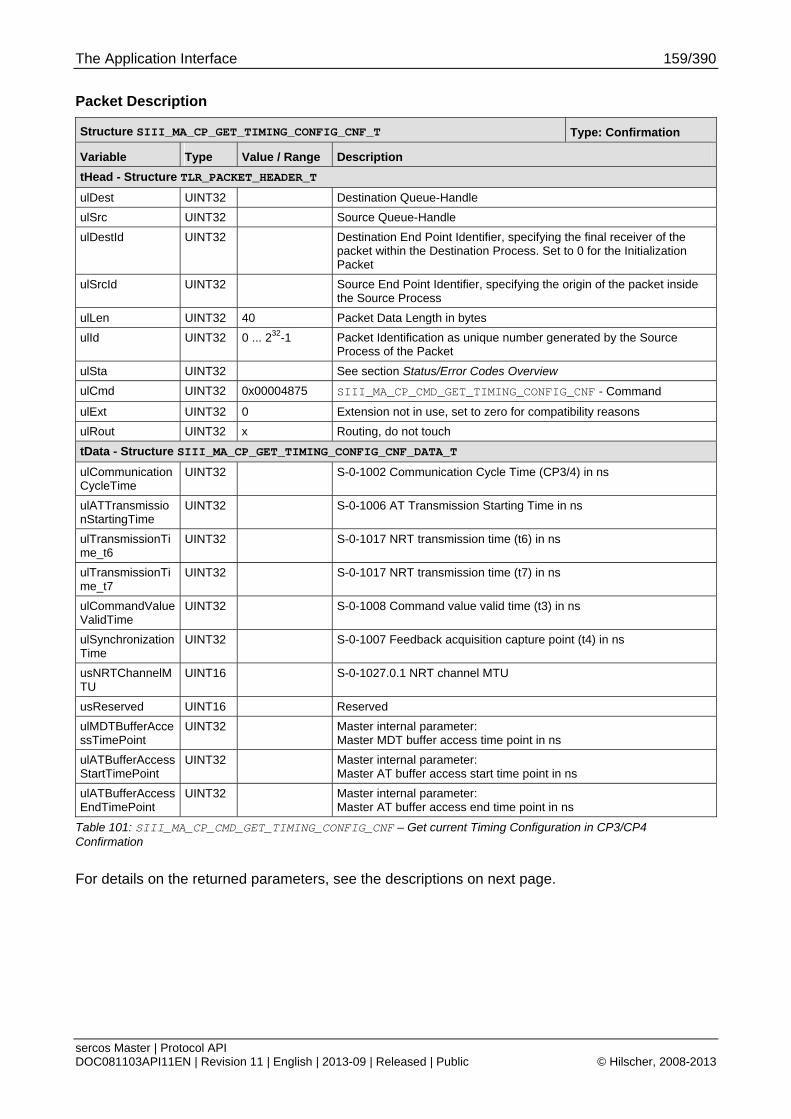
The Application Interface 159/390
sercos Master | Protocol API DOC081103API11EN | Revision 11 | English | 2013-09 | Released | Public © Hilscher, 2008-2013
Packet Description
Structure SIII_MA_CP_GET_TIMING_CONFIG_CNF_T Type: Confirmation
Variable Type Value / Range Description
tHead - Structure TLR_PACKET_HEADER_T
ulDest UINT32 Destination Queue-Handle
ulSrc UINT32 Source Queue-Handle
ulDestId UINT32 Destination End Point Identifier, specifying the final receiver of the packet within the Destination Process. Set to 0 for the Initialization Packet
ulSrcId UINT32 Source End Point Identifier, specifying the origin of the packet inside the Source Process
ulLen UINT32 40 Packet Data Length in bytes
ulId UINT32 0 ... 232-1 Packet Identification as unique number generated by the Source Process of the Packet
ulSta UINT32 See section Status/Error Codes Overview
ulCmd UINT32 0x00004875 SIII_MA_CP_CMD_GET_TIMING_CONFIG_CNF - Command
ulExt UINT32 0 Extension not in use, set to zero for compatibility reasons
ulRout UINT32 x Routing, do not touch
tData - Structure SIII_MA_CP_GET_TIMING_CONFIG_CNF_DATA_T
ulCommunicationCycleTime
UINT32 S-0-1002 Communication Cycle Time (CP3/4) in ns
ulATTransmissionStartingTime
UINT32 S-0-1006 AT Transmission Starting Time in ns
ulTransmissionTime_t6
UINT32 S-0-1017 NRT transmission time (t6) in ns
ulTransmissionTime_t7
UINT32 S-0-1017 NRT transmission time (t7) in ns
ulCommandValueValidTime
UINT32 S-0-1008 Command value valid time (t3) in ns
ulSynchronizationTime
UINT32 S-0-1007 Feedback acquisition capture point (t4) in ns
usNRTChannelMTU
UINT16 S-0-1027.0.1 NRT channel MTU
usReserved UINT16 Reserved
ulMDTBufferAccessTimePoint
UINT32 Master internal parameter: Master MDT buffer access time point in ns
ulATBufferAccessStartTimePoint
UINT32 Master internal parameter: Master AT buffer access start time point in ns
ulATBufferAccessEndTimePoint
UINT32 Master internal parameter: Master AT buffer access end time point in ns
Table 101: SIII_MA_CP_CMD_GET_TIMING_CONFIG_CNF – Get current Timing Configuration in CP3/CP4 Confirmation
For details on the returned parameters, see the descriptions on next page.
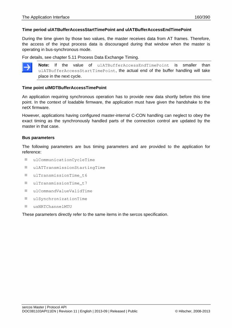
The Application Interface 160/390
sercos Master | Protocol API DOC081103API11EN | Revision 11 | English | 2013-09 | Released | Public © Hilscher, 2008-2013
Time period ulATBufferAccessStartTimePoint and ulATBufferAccessEndTimePoint
During the time given by those two values, the master receives data from AT frames. Therefore, the access of the input process data is discouraged during that window when the master is operating in bus-synchronous mode.
For details, see chapter 5.11 Process Data Exchange Timing.
Note: If the value of ulATBufferAccessEndTimePoint is smaller than ulATBufferAccessStartTimePoint, the actual end of the buffer handling will take place in the next cycle.
Time point ulMDTBufferAccessTimePoint
An application requiring synchronous operation has to provide new data shortly before this time point. In the context of loadable firmware, the application must have given the handshake to the netX firmware.
However, applications having configured master-internal C-CON handling can neglect to obey the exact timing as the synchronously handled parts of the connection control are updated by the master in that case.
Bus parameters
The following parameters are bus timing parameters and are provided to the application for reference:
ulCommunicationCycleTime
ulATTransmissionStartingTime
ulTransmissionTime_t6
ulTransmissionTime_t7
ulCommandValueValidTime
ulSynchronizationTime
usNRTChannelMTU
These parameters directly refer to the same items in the sercos specification.
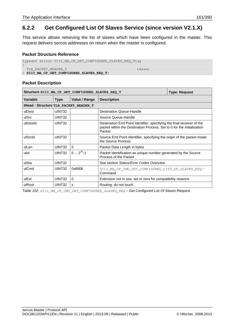
The Application Interface 161/390
sercos Master | Protocol API DOC081103API11EN | Revision 11 | English | 2013-09 | Released | Public © Hilscher, 2008-2013
6.2.2 Get Configured List Of Slaves Service (since version V2.1.X)
This service allows retrieving the list of slaves which have been configured in the master. This request delivers sercos addresses on return when the master is configured.
Packet Structure Reference
typedef struct SIII_MA_CP_GET_CONFIGURED_SLAVES_REQ_Ttag { TLR_PACKET_HEADER_T tHead; } SIII_MA_CP_GET_CONFIGURED_SLAVES_REQ_T;
Packet Description
Structure SIII_MA_CP_GET_CONFIGURED_SLAVES_REQ_T Type: Request
Variable Type Value / Range Description
tHead - Structure TLR_PACKET_HEADER_T
ulDest UINT32 Destination Queue-Handle
ulSrc UINT32 Source Queue-Handle
ulDestId UINT32 Destination End Point Identifier, specifying the final receiver of the packet within the Destination Process. Set to 0 for the Initialization Packet
ulSrcId UINT32 Source End Point Identifier, specifying the origin of the packet inside the Source Process
ulLen UINT32 0 Packet Data Length in bytes
ulId UINT32 0 ... 232-1 Packet Identification as unique number generated by the Source Process of the Packet
ulSta UINT32 See section Status/Error Codes Overview
ulCmd UINT32 0x8906 SIII_MA_CP_CMD_GET_CONFIGURED_LIST_OF_SLAVES_REQ - Command
ulExt UINT32 0 Extension not in use, set to zero for compatibility reasons
ulRout UINT32 x Routing, do not touch
Table 102: SIII_MA_CP_CMD_GET_CONFIGURED_SLAVES_REQ – Get Configured List Of Slaves Request
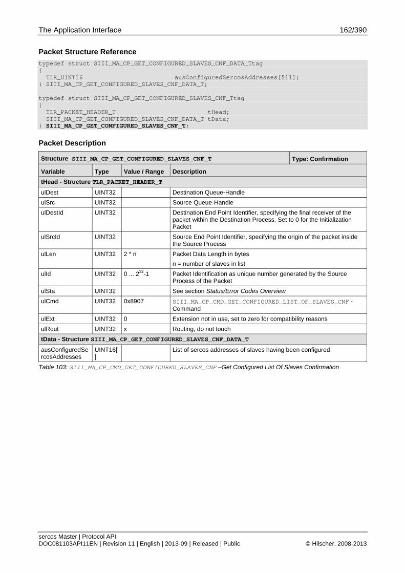
The Application Interface 162/390
sercos Master | Protocol API DOC081103API11EN | Revision 11 | English | 2013-09 | Released | Public © Hilscher, 2008-2013
Packet Structure Reference
typedef struct SIII_MA_CP_GET_CONFIGURED_SLAVES_CNF_DATA_Ttag { TLR_UINT16 ausConfiguredSercosAddresses[511]; } SIII_MA_CP_GET_CONFIGURED_SLAVES_CNF_DATA_T; typedef struct SIII_MA_CP_GET_CONFIGURED_SLAVES_CNF_Ttag { TLR_PACKET_HEADER_T tHead; SIII_MA_CP_GET_CONFIGURED_SLAVES_CNF_DATA_T tData; } SIII_MA_CP_GET_CONFIGURED_SLAVES_CNF_T;
Packet Description
Structure SIII_MA_CP_GET_CONFIGURED_SLAVES_CNF_T Type: Confirmation
Variable Type Value / Range Description
tHead - Structure TLR_PACKET_HEADER_T
ulDest UINT32 Destination Queue-Handle
ulSrc UINT32 Source Queue-Handle
ulDestId UINT32 Destination End Point Identifier, specifying the final receiver of the packet within the Destination Process. Set to 0 for the Initialization Packet
ulSrcId UINT32 Source End Point Identifier, specifying the origin of the packet inside the Source Process
ulLen UINT32 2 * n Packet Data Length in bytes
n = number of slaves in list
ulId UINT32 0 ... 232-1 Packet Identification as unique number generated by the Source Process of the Packet
ulSta UINT32 See section Status/Error Codes Overview
ulCmd UINT32 0x8907 SIII_MA_CP_CMD_GET_CONFIGURED_LIST_OF_SLAVES_CNF - Command
ulExt UINT32 0 Extension not in use, set to zero for compatibility reasons
ulRout UINT32 x Routing, do not touch
tData - Structure SIII_MA_CP_GET_CONFIGURED_SLAVES_CNF_DATA_T
ausConfiguredSercosAddresses
UINT16[]
List of sercos addresses of slaves having been configured
Table 103: SIII_MA_CP_CMD_GET_CONFIGURED_SLAVES_CNF –Get Configured List Of Slaves Confirmation
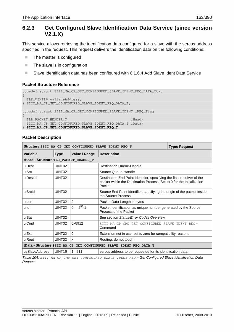
The Application Interface 163/390
sercos Master | Protocol API DOC081103API11EN | Revision 11 | English | 2013-09 | Released | Public © Hilscher, 2008-2013
6.2.3 Get Configured Slave Identification Data Service (since version V2.1.X)
This service allows retrieving the identification data configured for a slave with the sercos address specified in the request. This request delivers the identification data on the following conditions:
The master is configured
The slave is in configuration
Slave Identification data has been configured with 6.1.6.4 Add Slave Ident Data Service
Packet Structure Reference
typedef struct SIII_MA_CP_GET_CONFIGURED_SLAVE_IDENT_REQ_DATA_Ttag { TLR_UINT16 usSlaveAddress; } SIII_MA_CP_GET_CONFIGURED_SLAVE_IDENT_REQ_DATA_T; typedef struct SIII_MA_CP_GET_CONFIGURED_SLAVE_IDENT _REQ_Ttag { TLR_PACKET_HEADER_T tHead; SIII_MA_CP_GET_CONFIGURED_SLAVE_IDENT_REQ_DATA_T tData; } SIII_MA_CP_GET_CONFIGURED_SLAVE_IDENT_REQ_T;
Packet Description
Structure SIII_MA_CP_GET_CONFIGURED_SLAVE_IDENT_REQ_T Type: Request
Variable Type Value / Range Description
tHead - Structure TLR_PACKET_HEADER_T
ulDest UINT32 Destination Queue-Handle
ulSrc UINT32 Source Queue-Handle
ulDestId UINT32 Destination End Point Identifier, specifying the final receiver of the packet within the Destination Process. Set to 0 for the Initialization Packet
ulSrcId UINT32 Source End Point Identifier, specifying the origin of the packet inside the Source Process
ulLen UINT32 2 Packet Data Length in bytes
ulId UINT32 0 ... 232-1 Packet Identification as unique number generated by the Source Process of the Packet
ulSta UINT32 See section Status/Error Codes Overview
ulCmd UINT32 0x8912 SIII_MA_CP_CMD_GET_CONFIGURED_SLAVE_IDENT_REQ – Command
ulExt UINT32 0 Extension not in use, set to zero for compatibility reasons
ulRout UINT32 x Routing, do not touch
tData - Structure SIII_MA_CP_GET_CONFIGURED_SLAVE_IDENT_REQ_DATA_T
usSlaveAddress UINT16 1.. 511 sercos address to be requested for its identification data
Table 104: SIII_MA_CP_CMD_GET_CONFIGURED_SLAVE_IDENT_REQ – Get Configured Slave Identification Data Request
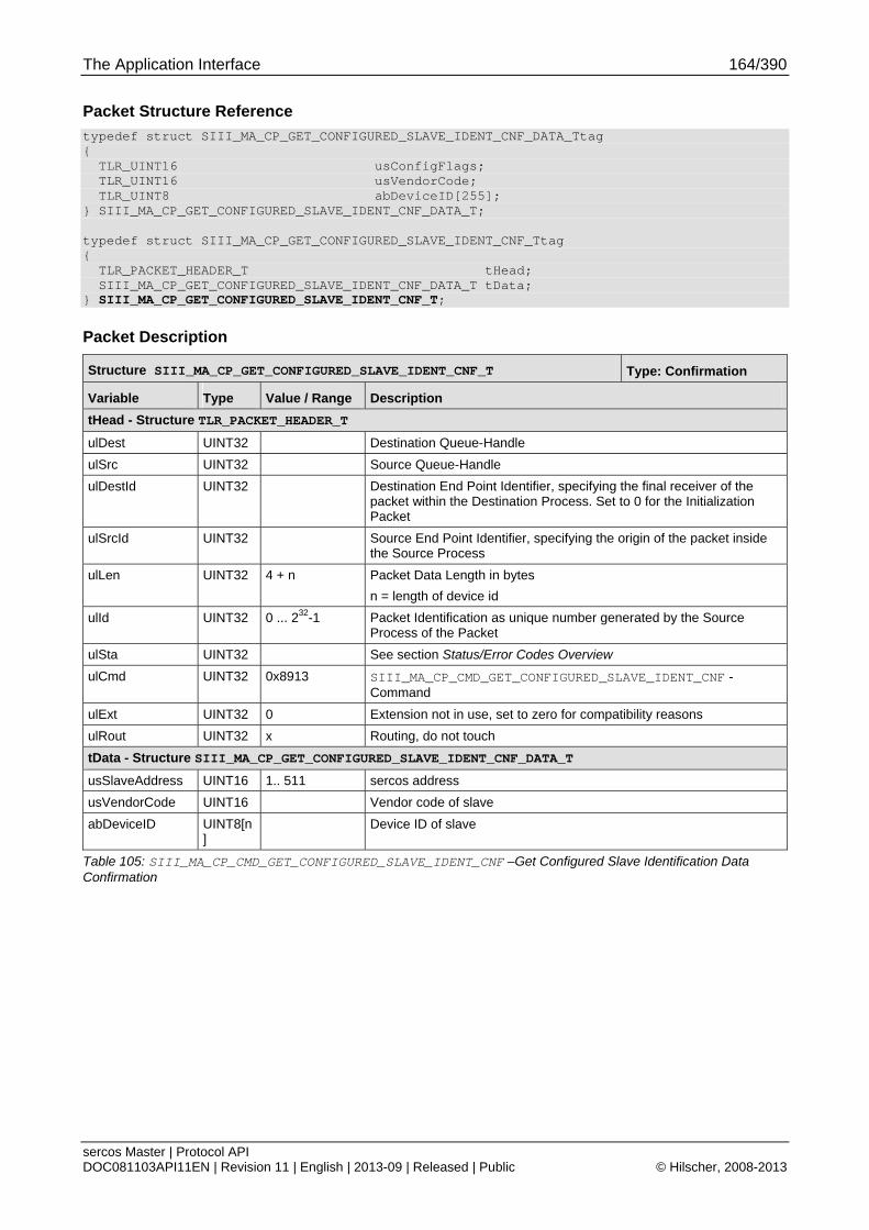
The Application Interface 164/390
sercos Master | Protocol API DOC081103API11EN | Revision 11 | English | 2013-09 | Released | Public © Hilscher, 2008-2013
Packet Structure Reference
typedef struct SIII_MA_CP_GET_CONFIGURED_SLAVE_IDENT_CNF_DATA_Ttag { TLR_UINT16 usConfigFlags; TLR_UINT16 usVendorCode; TLR_UINT8 abDeviceID[255]; } SIII_MA_CP_GET_CONFIGURED_SLAVE_IDENT_CNF_DATA_T; typedef struct SIII_MA_CP_GET_CONFIGURED_SLAVE_IDENT_CNF_Ttag { TLR_PACKET_HEADER_T tHead; SIII_MA_CP_GET_CONFIGURED_SLAVE_IDENT_CNF_DATA_T tData; } SIII_MA_CP_GET_CONFIGURED_SLAVE_IDENT_CNF_T;
Packet Description
Structure SIII_MA_CP_GET_CONFIGURED_SLAVE_IDENT_CNF_T Type: Confirmation
Variable Type Value / Range Description
tHead - Structure TLR_PACKET_HEADER_T
ulDest UINT32 Destination Queue-Handle
ulSrc UINT32 Source Queue-Handle
ulDestId UINT32 Destination End Point Identifier, specifying the final receiver of the packet within the Destination Process. Set to 0 for the Initialization Packet
ulSrcId UINT32 Source End Point Identifier, specifying the origin of the packet inside the Source Process
ulLen UINT32 4 + n Packet Data Length in bytes
n = length of device id
ulId UINT32 0 ... 232-1 Packet Identification as unique number generated by the Source Process of the Packet
ulSta UINT32 See section Status/Error Codes Overview
ulCmd UINT32 0x8913 SIII_MA_CP_CMD_GET_CONFIGURED_SLAVE_IDENT_CNF - Command
ulExt UINT32 0 Extension not in use, set to zero for compatibility reasons
ulRout UINT32 x Routing, do not touch
tData - Structure SIII_MA_CP_GET_CONFIGURED_SLAVE_IDENT_CNF_DATA_T
usSlaveAddress UINT16 1.. 511 sercos address
usVendorCode UINT16 Vendor code of slave
abDeviceID UINT8[n]
Device ID of slave
Table 105: SIII_MA_CP_CMD_GET_CONFIGURED_SLAVE_IDENT_CNF –Get Configured Slave Identification Data Confirmation
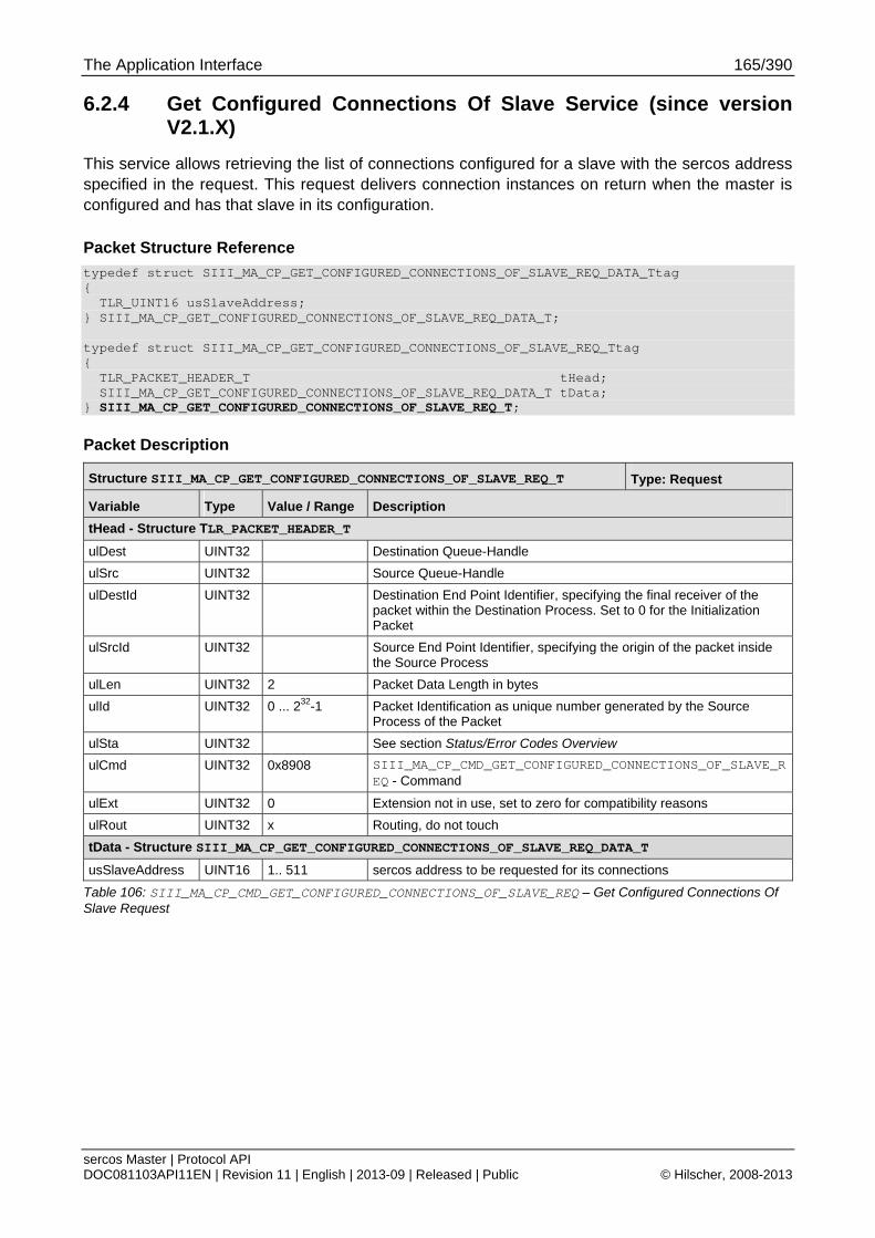
The Application Interface 165/390
sercos Master | Protocol API DOC081103API11EN | Revision 11 | English | 2013-09 | Released | Public © Hilscher, 2008-2013
6.2.4 Get Configured Connections Of Slave Service (since version V2.1.X)
This service allows retrieving the list of connections configured for a slave with the sercos address specified in the request. This request delivers connection instances on return when the master is configured and has that slave in its configuration.
Packet Structure Reference
typedef struct SIII_MA_CP_GET_CONFIGURED_CONNECTIONS_OF_SLAVE_REQ_DATA_Ttag { TLR_UINT16 usSlaveAddress; } SIII_MA_CP_GET_CONFIGURED_CONNECTIONS_OF_SLAVE_REQ_DATA_T; typedef struct SIII_MA_CP_GET_CONFIGURED_CONNECTIONS_OF_SLAVE_REQ_Ttag { TLR_PACKET_HEADER_T tHead; SIII_MA_CP_GET_CONFIGURED_CONNECTIONS_OF_SLAVE_REQ_DATA_T tData; } SIII_MA_CP_GET_CONFIGURED_CONNECTIONS_OF_SLAVE_REQ_T;
Packet Description
Structure SIII_MA_CP_GET_CONFIGURED_CONNECTIONS_OF_SLAVE_REQ_T Type: Request
Variable Type Value / Range Description
tHead - Structure TLR_PACKET_HEADER_T
ulDest UINT32 Destination Queue-Handle
ulSrc UINT32 Source Queue-Handle
ulDestId UINT32 Destination End Point Identifier, specifying the final receiver of the packet within the Destination Process. Set to 0 for the Initialization Packet
ulSrcId UINT32 Source End Point Identifier, specifying the origin of the packet inside the Source Process
ulLen UINT32 2 Packet Data Length in bytes
ulId UINT32 0 ... 232-1 Packet Identification as unique number generated by the Source Process of the Packet
ulSta UINT32 See section Status/Error Codes Overview
ulCmd UINT32 0x8908 SIII_MA_CP_CMD_GET_CONFIGURED_CONNECTIONS_OF_SLAVE_REQ - Command
ulExt UINT32 0 Extension not in use, set to zero for compatibility reasons
ulRout UINT32 x Routing, do not touch
tData - Structure SIII_MA_CP_GET_CONFIGURED_CONNECTIONS_OF_SLAVE_REQ_DATA_T
usSlaveAddress UINT16 1.. 511 sercos address to be requested for its connections
Table 106: SIII_MA_CP_CMD_GET_CONFIGURED_CONNECTIONS_OF_SLAVE_REQ – Get Configured Connections Of Slave Request
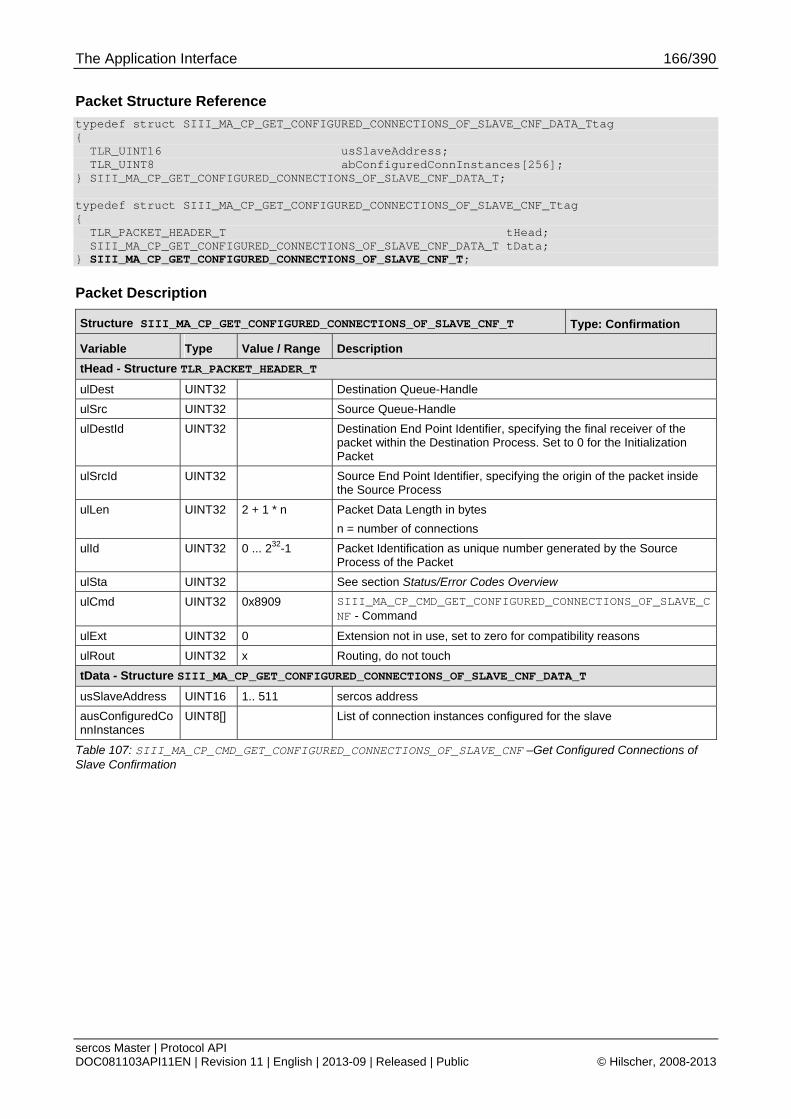
The Application Interface 166/390
sercos Master | Protocol API DOC081103API11EN | Revision 11 | English | 2013-09 | Released | Public © Hilscher, 2008-2013
Packet Structure Reference
typedef struct SIII_MA_CP_GET_CONFIGURED_CONNECTIONS_OF_SLAVE_CNF_DATA_Ttag { TLR_UINT16 usSlaveAddress; TLR_UINT8 abConfiguredConnInstances[256]; } SIII_MA_CP_GET_CONFIGURED_CONNECTIONS_OF_SLAVE_CNF_DATA_T; typedef struct SIII_MA_CP_GET_CONFIGURED_CONNECTIONS_OF_SLAVE_CNF_Ttag { TLR_PACKET_HEADER_T tHead; SIII_MA_CP_GET_CONFIGURED_CONNECTIONS_OF_SLAVE_CNF_DATA_T tData; } SIII_MA_CP_GET_CONFIGURED_CONNECTIONS_OF_SLAVE_CNF_T;
Packet Description
Structure SIII_MA_CP_GET_CONFIGURED_CONNECTIONS_OF_SLAVE_CNF_T Type: Confirmation
Variable Type Value / Range Description
tHead - Structure TLR_PACKET_HEADER_T
ulDest UINT32 Destination Queue-Handle
ulSrc UINT32 Source Queue-Handle
ulDestId UINT32 Destination End Point Identifier, specifying the final receiver of the packet within the Destination Process. Set to 0 for the Initialization Packet
ulSrcId UINT32 Source End Point Identifier, specifying the origin of the packet inside the Source Process
ulLen UINT32 2 + 1 * n Packet Data Length in bytes
n = number of connections
ulId UINT32 0 ... 232-1 Packet Identification as unique number generated by the Source Process of the Packet
ulSta UINT32 See section Status/Error Codes Overview
ulCmd UINT32 0x8909 SIII_MA_CP_CMD_GET_CONFIGURED_CONNECTIONS_OF_SLAVE_CNF - Command
ulExt UINT32 0 Extension not in use, set to zero for compatibility reasons
ulRout UINT32 x Routing, do not touch
tData - Structure SIII_MA_CP_GET_CONFIGURED_CONNECTIONS_OF_SLAVE_CNF_DATA_T
usSlaveAddress UINT16 1.. 511 sercos address
ausConfiguredConnInstances
UINT8[] List of connection instances configured for the slave
Table 107: SIII_MA_CP_CMD_GET_CONFIGURED_CONNECTIONS_OF_SLAVE_CNF –Get Configured Connections of Slave Confirmation
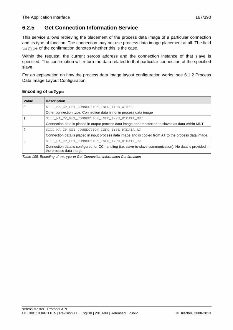
The Application Interface 167/390
sercos Master | Protocol API DOC081103API11EN | Revision 11 | English | 2013-09 | Released | Public © Hilscher, 2008-2013
6.2.5 Get Connection Information Service
This service allows retrieving the placement of the process data image of a particular connection and its type of function. The connection may not use process data image placement at all. The field usType of the confirmation denotes whether this is the case.
Within the request, the current sercos address and the connection instance of that slave is specified. The confirmation will return the data related to that particular connection of the specified slave.
For an explanation on how the process data image layout configuration works, see 6.1.2 Process Data Image Layout Configuration.
Encoding of usType
Value Description
0 SIII_MA_CP_GET_CONNECTION_INFO_TYPE_OTHER
Other connection type. Connection data is not in process data image
1 SIII_MA_CP_GET_CONNECTION_INFO_TYPE_RTDATA_MDT
Connection data is placed in output process data image and transferred to slaves as data within MDT
2 SIII_MA_CP_GET_CONNECTION_INFO_TYPE_RTDATA_AT
Connection data is placed in input process data image and is copied from AT to the process data image.
3 SIII_MA_CP_GET_CONNECTION_INFO_TYPE_RTDATA_CC
Connection data is configured for CC handling (i.e. slave-to-slave communication). No data is provided in the process data image.
Table 108: Encoding of usType in Get Connection Information Confirmation
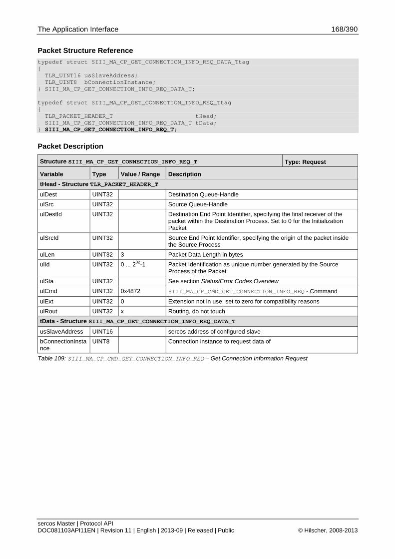
The Application Interface 168/390
sercos Master | Protocol API DOC081103API11EN | Revision 11 | English | 2013-09 | Released | Public © Hilscher, 2008-2013
Packet Structure Reference
typedef struct SIII_MA_CP_GET_CONNECTION_INFO_REQ_DATA_Ttag { TLR_UINT16 usSlaveAddress; TLR_UINT8 bConnectionInstance; } SIII_MA_CP_GET_CONNECTION_INFO_REQ_DATA_T; typedef struct SIII_MA_CP_GET_CONNECTION_INFO_REQ_Ttag { TLR_PACKET_HEADER_T tHead; SIII_MA_CP_GET_CONNECTION_INFO_REQ_DATA_T tData; } SIII_MA_CP_GET_CONNECTION_INFO_REQ_T;
Packet Description
Structure SIII_MA_CP_GET_CONNECTION_INFO_REQ_T Type: Request
Variable Type Value / Range Description
tHead - Structure TLR_PACKET_HEADER_T
ulDest UINT32 Destination Queue-Handle
ulSrc UINT32 Source Queue-Handle
ulDestId UINT32 Destination End Point Identifier, specifying the final receiver of the packet within the Destination Process. Set to 0 for the Initialization Packet
ulSrcId UINT32 Source End Point Identifier, specifying the origin of the packet inside the Source Process
ulLen UINT32 3 Packet Data Length in bytes
ulId UINT32 0 ... 232-1 Packet Identification as unique number generated by the Source Process of the Packet
ulSta UINT32 See section Status/Error Codes Overview
ulCmd UINT32 0x4872 SIII_MA_CP_CMD_GET_CONNECTION_INFO_REQ - Command
ulExt UINT32 0 Extension not in use, set to zero for compatibility reasons
ulRout UINT32 x Routing, do not touch
tData - Structure SIII_MA_CP_GET_CONNECTION_INFO_REQ_DATA_T
usSlaveAddress UINT16 sercos address of configured slave
bConnectionInstance
UINT8 Connection instance to request data of
Table 109: SIII_MA_CP_CMD_GET_CONNECTION_INFO_REQ – Get Connection Information Request
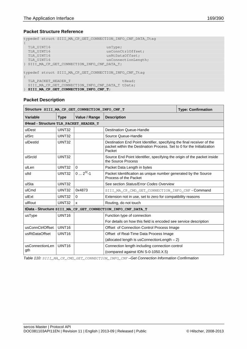
The Application Interface 169/390
sercos Master | Protocol API DOC081103API11EN | Revision 11 | English | 2013-09 | Released | Public © Hilscher, 2008-2013
Packet Structure Reference
typedef struct SIII_MA_CP_GET_CONNECTION_INFO_CNF_DATA_Ttag { TLR_UINT16 usType; TLR_UINT16 usConnCtrlOffset; TLR_UINT16 usRtDataOffset; TLR_UINT16 usConnectionLength; } SIII_MA_CP_GET_CONNECTION_INFO_CNF_DATA_T; typedef struct SIII_MA_CP_GET_CONNECTION_INFO_CNF_Ttag { TLR_PACKET_HEADER_T tHead; SIII_MA_CP_GET_CONNECTION_INFO_CNF_DATA_T tData; } SIII_MA_CP_GET_CONNECTION_INFO_CNF_T;
Packet Description
Structure SIII_MA_CP_GET_CONNECTION_INFO_CNF_T Type: Confirmation
Variable Type Value / Range Description
tHead - Structure TLR_PACKET_HEADER_T
ulDest UINT32 Destination Queue-Handle
ulSrc UINT32 Source Queue-Handle
ulDestId UINT32 Destination End Point Identifier, specifying the final receiver of the packet within the Destination Process. Set to 0 for the Initialization Packet
ulSrcId UINT32 Source End Point Identifier, specifying the origin of the packet inside the Source Process
ulLen UINT32 0 Packet Data Length in bytes
ulId UINT32 0 ... 232-1 Packet Identification as unique number generated by the Source Process of the Packet
ulSta UINT32 See section Status/Error Codes Overview
ulCmd UINT32 0x4873 SIII_MA_CP_CMD_GET_CONNECTION_INFO_CNF - Command
ulExt UINT32 0 Extension not in use, set to zero for compatibility reasons
ulRout UINT32 x Routing, do not touch
tData - Structure SIII_MA_CP_GET_CONNECTION_INFO_CNF_DATA_T
usType UINT16 Function type of connection
For details on how this field is encoded see service description
usConnCtrlOffset UINT16 Offset of Connection Control Process Image
usRtDataOffset UINT16 Offset of Real-Time Data Process Image
(allocated length is usConnectionLength – 2)
usConnectionLength
UINT16 Connection length including connection control
(compared against IDN S-0-1050.X.5)
Table 110: SIII_MA_CP_CMD_GET_CONNECTION_INFO_CNF –Get Connection Information Confirmation
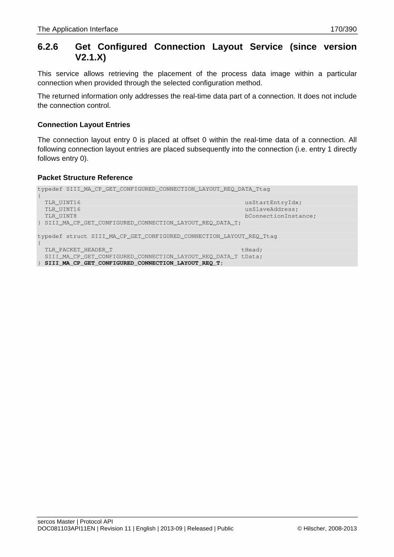
The Application Interface 170/390
sercos Master | Protocol API DOC081103API11EN | Revision 11 | English | 2013-09 | Released | Public © Hilscher, 2008-2013
6.2.6 Get Configured Connection Layout Service (since version V2.1.X)
This service allows retrieving the placement of the process data image within a particular connection when provided through the selected configuration method.
The returned information only addresses the real-time data part of a connection. It does not include the connection control.
Connection Layout Entries
The connection layout entry 0 is placed at offset 0 within the real-time data of a connection. All following connection layout entries are placed subsequently into the connection (i.e. entry 1 directly follows entry 0).
Packet Structure Reference
typedef SIII_MA_CP_GET_CONFIGURED_CONNECTION_LAYOUT_REQ_DATA_Ttag { TLR_UINT16 usStartEntryIdx; TLR_UINT16 usSlaveAddress; TLR_UINT8 bConnectionInstance; } SIII_MA_CP_GET_CONFIGURED_CONNECTION_LAYOUT_REQ_DATA_T; typedef struct SIII_MA_CP_GET_CONFIGURED_CONNECTION_LAYOUT_REQ_Ttag { TLR_PACKET_HEADER_T tHead; SIII_MA_CP_GET_CONFIGURED_CONNECTION_LAYOUT_REQ_DATA_T tData; } SIII_MA_CP_GET_CONFIGURED_CONNECTION_LAYOUT_REQ_T;
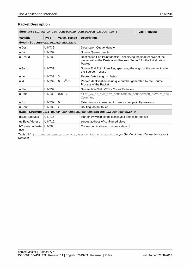
The Application Interface 171/390
sercos Master | Protocol API DOC081103API11EN | Revision 11 | English | 2013-09 | Released | Public © Hilscher, 2008-2013
Packet Description
Structure SIII_MA_CP_GET_CONFIGURED_CONNECTION_LAYOUT_REQ_T Type: Request
Variable Type Value / Range Description
tHead - Structure TLR_PACKET_HEADER_T
ulDest UINT32 Destination Queue-Handle
ulSrc UINT32 Source Queue-Handle
ulDestId UINT32 Destination End Point Identifier, specifying the final receiver of the packet within the Destination Process. Set to 0 for the Initialization Packet
ulSrcId UINT32 Source End Point Identifier, specifying the origin of the packet inside the Source Process
ulLen UINT32 3 Packet Data Length in bytes
ulId UINT32 0 ... 232-1 Packet Identification as unique number generated by the Source Process of the Packet
ulSta UINT32 See section Status/Error Codes Overview
ulCmd UINT32 0x8916 SIII_MA_CP_CMD_GET_CONFIGURED_CONNECTION_LAYOUT_REQ - Command
ulExt UINT32 0 Extension not in use, set to zero for compatibility reasons
ulRout UINT32 x Routing, do not touch
tData - Structure SIII_MA_CP_GET_CONFIGURED_CONNECTION_LAYOUT_REQ_DATA_T
usStartEntryIdx UINT16 start entry within connection layout entries to retrieve
usSlaveAddress UINT16 sercos address of configured slave
bConnectionInstance
UINT8 Connection instance to request data of
Table 111: SIII_MA_CP_CMD_GET_CONFIGURED_CONNECTION_LAYOUT_REQ – Get Configured Connection Layout Request
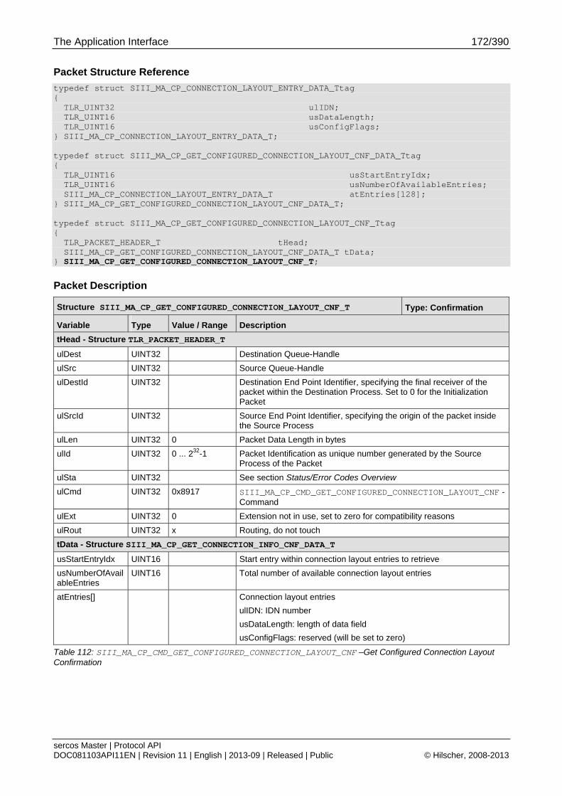
The Application Interface 172/390
sercos Master | Protocol API DOC081103API11EN | Revision 11 | English | 2013-09 | Released | Public © Hilscher, 2008-2013
Packet Structure Reference
typedef struct SIII_MA_CP_CONNECTION_LAYOUT_ENTRY_DATA_Ttag { TLR_UINT32 ulIDN; TLR_UINT16 usDataLength; TLR_UINT16 usConfigFlags; } SIII_MA_CP_CONNECTION_LAYOUT_ENTRY_DATA_T; typedef struct SIII_MA_CP_GET_CONFIGURED_CONNECTION_LAYOUT_CNF_DATA_Ttag { TLR_UINT16 usStartEntryIdx; TLR_UINT16 usNumberOfAvailableEntries; SIII_MA_CP_CONNECTION_LAYOUT_ENTRY_DATA_T atEntries[128]; } SIII_MA_CP_GET_CONFIGURED_CONNECTION_LAYOUT_CNF_DATA_T; typedef struct SIII_MA_CP_GET_CONFIGURED_CONNECTION_LAYOUT_CNF_Ttag { TLR_PACKET_HEADER_T tHead; SIII_MA_CP_GET_CONFIGURED_CONNECTION_LAYOUT_CNF_DATA_T tData; } SIII_MA_CP_GET_CONFIGURED_CONNECTION_LAYOUT_CNF_T;
Packet Description
Structure SIII_MA_CP_GET_CONFIGURED_CONNECTION_LAYOUT_CNF_T Type: Confirmation
Variable Type Value / Range Description
tHead - Structure TLR_PACKET_HEADER_T
ulDest UINT32 Destination Queue-Handle
ulSrc UINT32 Source Queue-Handle
ulDestId UINT32 Destination End Point Identifier, specifying the final receiver of the packet within the Destination Process. Set to 0 for the Initialization Packet
ulSrcId UINT32 Source End Point Identifier, specifying the origin of the packet inside the Source Process
ulLen UINT32 0 Packet Data Length in bytes
ulId UINT32 0 ... 232-1 Packet Identification as unique number generated by the Source Process of the Packet
ulSta UINT32 See section Status/Error Codes Overview
ulCmd UINT32 0x8917 SIII_MA_CP_CMD_GET_CONFIGURED_CONNECTION_LAYOUT_CNF - Command
ulExt UINT32 0 Extension not in use, set to zero for compatibility reasons
ulRout UINT32 x Routing, do not touch
tData - Structure SIII_MA_CP_GET_CONNECTION_INFO_CNF_DATA_T
usStartEntryIdx UINT16 Start entry within connection layout entries to retrieve
usNumberOfAvailableEntries
UINT16 Total number of available connection layout entries
atEntries[] Connection layout entries
ulIDN: IDN number
usDataLength: length of data field
usConfigFlags: reserved (will be set to zero)
Table 112: SIII_MA_CP_CMD_GET_CONFIGURED_CONNECTION_LAYOUT_CNF –Get Configured Connection Layout Confirmation

The Application Interface 173/390
sercos Master | Protocol API DOC081103API11EN | Revision 11 | English | 2013-09 | Released | Public © Hilscher, 2008-2013
6.3 Phase Control
6.3.1 Architecture of Communication Phase Control
The master implements a separation between target phase setting and changing the communication phase. Therefore, the packets for setting the target phase will only set the new communication phase to reach. The confirmations return immediately. So, these do not indicate completion of the phase change at all.
In order to determine completion and current network status, the following services have to be used:
6.3.2.2 Get Current Phase Information Service
(Polling based, application actively requests for current status)
6.4 Status Indications
(Event based, master signals indications to the application)
BusOff and Setting theTarget Phase
The new target phase can be set when the master is set to BusOff. The request will be returned with the error code TLR_I_SIII_MA_CP_BUS_IS_OFF (0x40700060). However, the action of the packet is still executed.
Error Codes related to successful operation
TLR_S_OK (0x00000000)
The master has accepted the new target phase and will proceed to it.
TLR_I_SIII_MA_CP_BUS_IS_OFF (0x40700060)
The master has accepted the new target phase. However, BusOff locks it to NRT phase.
Indications and Setting the Target Phase
When the communication phase indication indicates the same phase as the last issued Set Target Phase request, the phase change has been completed successfully.
When the indication described at 6.4.2.3 Network Phase Change Aborted Indication is received, the phase change has been aborted due to an error during phase change.
Note: The diagnostic log can provide additional detail on the reason. For details about how to use the diagnostic log, see chapter 6.5 Diagnostic Log.
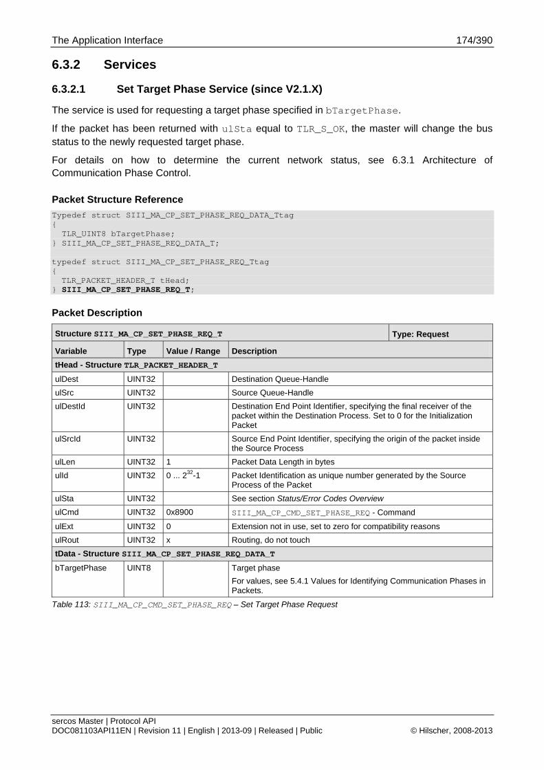
The Application Interface 174/390
sercos Master | Protocol API DOC081103API11EN | Revision 11 | English | 2013-09 | Released | Public © Hilscher, 2008-2013
6.3.2 Services
6.3.2.1 Set Target Phase Service (since V2.1.X)
The service is used for requesting a target phase specified in bTargetPhase.
If the packet has been returned with ulSta equal to TLR_S_OK, the master will change the bus status to the newly requested target phase.
For details on how to determine the current network status, see 6.3.1 Architecture of Communication Phase Control.
Packet Structure Reference
Typedef struct SIII_MA_CP_SET_PHASE_REQ_DATA_Ttag { TLR_UINT8 bTargetPhase; } SIII_MA_CP_SET_PHASE_REQ_DATA_T; typedef struct SIII_MA_CP_SET_PHASE_REQ_Ttag { TLR_PACKET_HEADER_T tHead;
} SIII_MA_CP_SET_PHASE_REQ_T;
Packet Description
Structure SIII_MA_CP_SET_PHASE_REQ_T Type: Request
Variable Type Value / Range Description
tHead - Structure TLR_PACKET_HEADER_T
ulDest UINT32 Destination Queue-Handle
ulSrc UINT32 Source Queue-Handle
ulDestId UINT32 Destination End Point Identifier, specifying the final receiver of the packet within the Destination Process. Set to 0 for the Initialization Packet
ulSrcId UINT32 Source End Point Identifier, specifying the origin of the packet inside the Source Process
ulLen UINT32 1 Packet Data Length in bytes
ulId UINT32 0 ... 232-1 Packet Identification as unique number generated by the Source Process of the Packet
ulSta UINT32 See section Status/Error Codes Overview
ulCmd UINT32 0x8900 SIII_MA_CP_CMD_SET_PHASE_REQ - Command
ulExt UINT32 0 Extension not in use, set to zero for compatibility reasons
ulRout UINT32 x Routing, do not touch
tData - Structure SIII_MA_CP_SET_PHASE_REQ_DATA_T
bTargetPhase UINT8 Target phase
For values, see 5.4.1 Values for Identifying Communication Phases in Packets.
Table 113: SIII_MA_CP_CMD_SET_PHASE_REQ – Set Target Phase Request
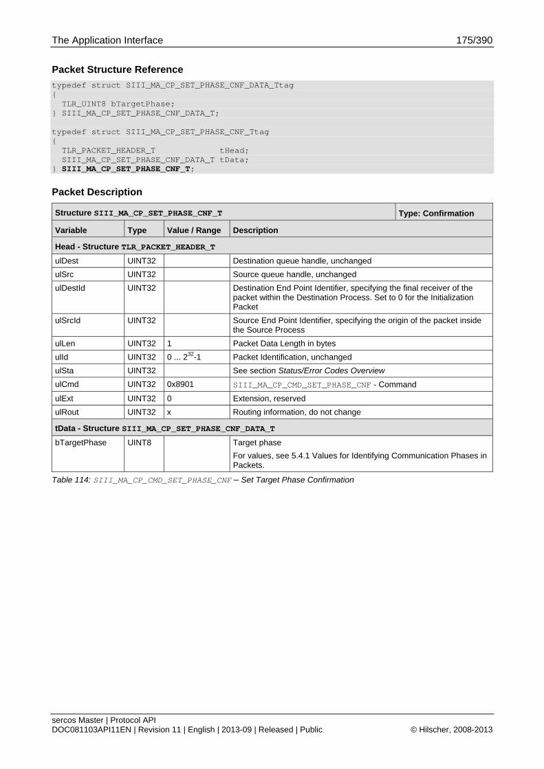
The Application Interface 175/390
sercos Master | Protocol API DOC081103API11EN | Revision 11 | English | 2013-09 | Released | Public © Hilscher, 2008-2013
Packet Structure Reference
typedef struct SIII_MA_CP_SET_PHASE_CNF_DATA_Ttag { TLR_UINT8 bTargetPhase; } SIII_MA_CP_SET_PHASE_CNF_DATA_T; typedef struct SIII_MA_CP_SET_PHASE_CNF_Ttag { TLR_PACKET_HEADER_T tHead; SIII_MA_CP_SET_PHASE_CNF_DATA_T tData; } SIII_MA_CP_SET_PHASE_CNF_T;
Packet Description
Structure SIII_MA_CP_SET_PHASE_CNF_T Type: Confirmation
Variable Type Value / Range Description
Head - Structure TLR_PACKET_HEADER_T
ulDest UINT32 Destination queue handle, unchanged
ulSrc UINT32 Source queue handle, unchanged
ulDestId UINT32 Destination End Point Identifier, specifying the final receiver of the packet within the Destination Process. Set to 0 for the Initialization Packet
ulSrcId UINT32 Source End Point Identifier, specifying the origin of the packet inside the Source Process
ulLen UINT32 1 Packet Data Length in bytes
ulId UINT32 0 ... 232-1 Packet Identification, unchanged
ulSta UINT32 See section Status/Error Codes Overview
ulCmd UINT32 0x8901 SIII_MA_CP_CMD_SET_PHASE_CNF - Command
ulExt UINT32 0 Extension, reserved
ulRout UINT32 x Routing information, do not change
tData - Structure SIII_MA_CP_SET_PHASE_CNF_DATA_T
bTargetPhase UINT8 Target phase
For values, see 5.4.1 Values for Identifying Communication Phases in Packets.
Table 114: SIII_MA_CP_CMD_SET_PHASE_CNF – Set Target Phase Confirmation
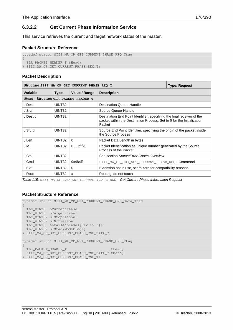
The Application Interface 176/390
sercos Master | Protocol API DOC081103API11EN | Revision 11 | English | 2013-09 | Released | Public © Hilscher, 2008-2013
6.3.2.2 Get Current Phase Information Service
This service retrieves the current and target network status of the master.
Packet Structure Reference
typedef struct SIII_MA_CP_GET_CURRENT_PHASE_REQ_Ttag { TLR_PACKET_HEADER_T tHead; } SIII_MA_CP_GET_CURRENT_PHASE_REQ_T;
Packet Description
Structure SIII_MA_CP_GET_CURRENT_PHASE_REQ_T Type: Request
Variable Type Value / Range Description
tHead - Structure TLR_PACKET_HEADER_T
ulDest UINT32 Destination Queue-Handle
ulSrc UINT32 Source Queue-Handle
ulDestId UINT32 Destination End Point Identifier, specifying the final receiver of the packet within the Destination Process. Set to 0 for the Initialization Packet
ulSrcId UINT32 Source End Point Identifier, specifying the origin of the packet inside the Source Process
ulLen UINT32 0 Packet Data Length in bytes
ulId UINT32 0 ... 232-1 Packet Identification as unique number generated by the Source Process of the Packet
ulSta UINT32 See section Status/Error Codes Overview
ulCmd UINT32 0x484E SIII_MA_CP_CMD_GET_CURRENT_PHASE_REQ - Command
ulExt UINT32 0 Extension not in use, set to zero for compatibility reasons
ulRout UINT32 x Routing, do not touch
Table 115: SIII_MA_CP_CMD_GET_CURRENT_PHASE_REQ – Get Current Phase Information Request
Packet Structure Reference
typedef struct SIII_MA_CP_GET_CURRENT_PHASE_CNF_DATA_Ttag { TLR_UINT8 bCurrentPhase; TLR_UINT8 bTargetPhase; TLR_UINT32 ulStopReason; TLR_UINT32 ulNrtReason; TLR_UINT8 abFailedSlaves[512 >> 3]; TLR_UINT32 ulStackModeFlags; } SIII_MA_CP_GET_CURRENT_PHASE_CNF_DATA_T; typedef struct SIII_MA_CP_GET_CURRENT_PHASE_CNF_Ttag { TLR_PACKET_HEADER_T tHead; SIII_MA_CP_GET_CURRENT_PHASE_CNF_DATA_T tData; } SIII_MA_CP_GET_CURRENT_PHASE_CNF_T;
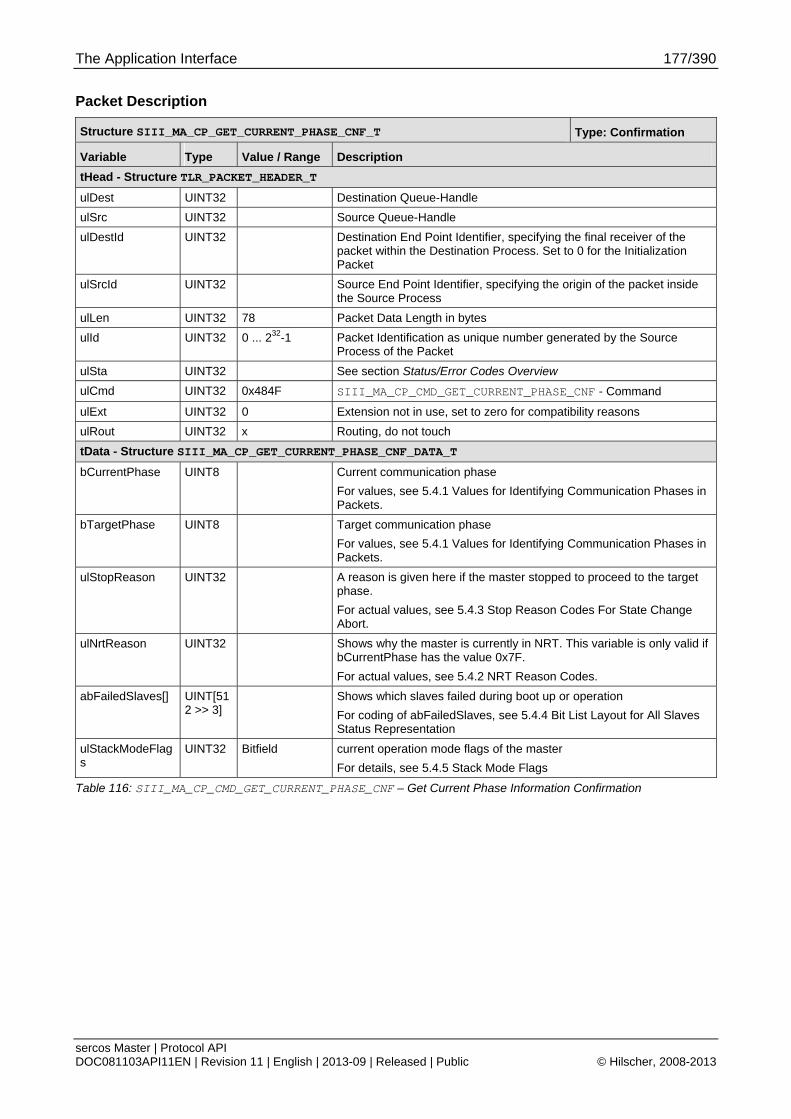
The Application Interface 177/390
sercos Master | Protocol API DOC081103API11EN | Revision 11 | English | 2013-09 | Released | Public © Hilscher, 2008-2013
Packet Description
Structure SIII_MA_CP_GET_CURRENT_PHASE_CNF_T Type: Confirmation
Variable Type Value / Range Description
tHead - Structure TLR_PACKET_HEADER_T
ulDest UINT32 Destination Queue-Handle
ulSrc UINT32 Source Queue-Handle
ulDestId UINT32 Destination End Point Identifier, specifying the final receiver of the packet within the Destination Process. Set to 0 for the Initialization Packet
ulSrcId UINT32 Source End Point Identifier, specifying the origin of the packet inside the Source Process
ulLen UINT32 78 Packet Data Length in bytes
ulId UINT32 0 ... 232-1 Packet Identification as unique number generated by the Source Process of the Packet
ulSta UINT32 See section Status/Error Codes Overview
ulCmd UINT32 0x484F SIII_MA_CP_CMD_GET_CURRENT_PHASE_CNF - Command
ulExt UINT32 0 Extension not in use, set to zero for compatibility reasons
ulRout UINT32 x Routing, do not touch
tData - Structure SIII_MA_CP_GET_CURRENT_PHASE_CNF_DATA_T
bCurrentPhase UINT8 Current communication phase
For values, see 5.4.1 Values for Identifying Communication Phases in Packets.
bTargetPhase UINT8 Target communication phase
For values, see 5.4.1 Values for Identifying Communication Phases in Packets.
ulStopReason UINT32 A reason is given here if the master stopped to proceed to the target phase.
For actual values, see 5.4.3 Stop Reason Codes For State Change Abort.
ulNrtReason UINT32 Shows why the master is currently in NRT. This variable is only valid if bCurrentPhase has the value 0x7F.
For actual values, see 5.4.2 NRT Reason Codes.
abFailedSlaves[] UINT[512 >> 3]
Shows which slaves failed during boot up or operation
For coding of abFailedSlaves, see 5.4.4 Bit List Layout for All Slaves Status Representation
ulStackModeFlags
UINT32 Bitfield current operation mode flags of the master
For details, see 5.4.5 Stack Mode Flags
Table 116: SIII_MA_CP_CMD_GET_CURRENT_PHASE_CNF – Get Current Phase Information Confirmation
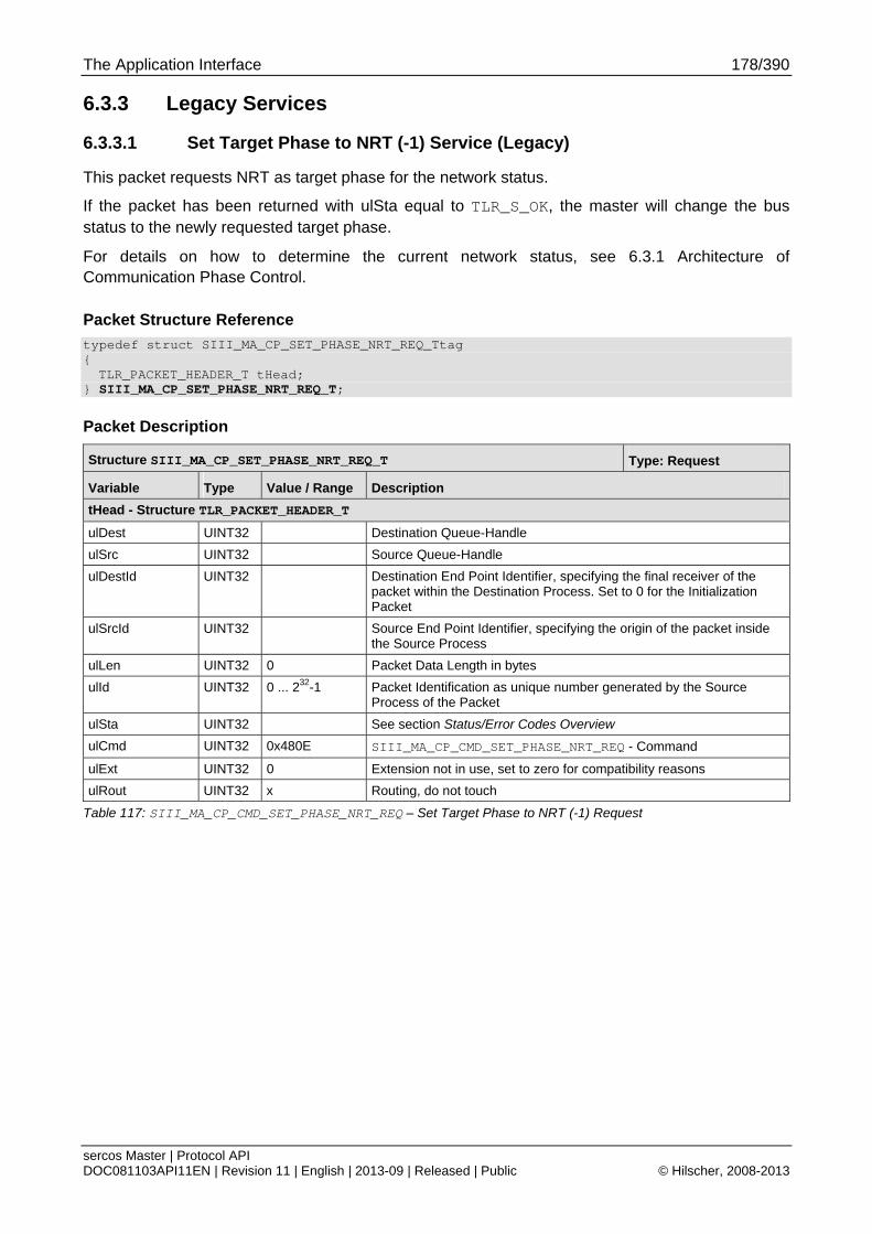
The Application Interface 178/390
sercos Master | Protocol API DOC081103API11EN | Revision 11 | English | 2013-09 | Released | Public © Hilscher, 2008-2013
6.3.3 Legacy Services
6.3.3.1 Set Target Phase to NRT (-1) Service (Legacy)
This packet requests NRT as target phase for the network status.
If the packet has been returned with ulSta equal to TLR_S_OK, the master will change the bus status to the newly requested target phase.
For details on how to determine the current network status, see 6.3.1 Architecture of Communication Phase Control.
Packet Structure Reference
typedef struct SIII_MA_CP_SET_PHASE_NRT_REQ_Ttag { TLR_PACKET_HEADER_T tHead;
} SIII_MA_CP_SET_PHASE_NRT_REQ_T;
Packet Description
Structure SIII_MA_CP_SET_PHASE_NRT_REQ_T Type: Request
Variable Type Value / Range Description
tHead - Structure TLR_PACKET_HEADER_T
ulDest UINT32 Destination Queue-Handle
ulSrc UINT32 Source Queue-Handle
ulDestId UINT32 Destination End Point Identifier, specifying the final receiver of the packet within the Destination Process. Set to 0 for the Initialization Packet
ulSrcId UINT32 Source End Point Identifier, specifying the origin of the packet inside the Source Process
ulLen UINT32 0 Packet Data Length in bytes
ulId UINT32 0 ... 232-1 Packet Identification as unique number generated by the Source Process of the Packet
ulSta UINT32 See section Status/Error Codes Overview
ulCmd UINT32 0x480E SIII_MA_CP_CMD_SET_PHASE_NRT_REQ - Command
ulExt UINT32 0 Extension not in use, set to zero for compatibility reasons
ulRout UINT32 x Routing, do not touch
Table 117: SIII_MA_CP_CMD_SET_PHASE_NRT_REQ – Set Target Phase to NRT (-1) Request
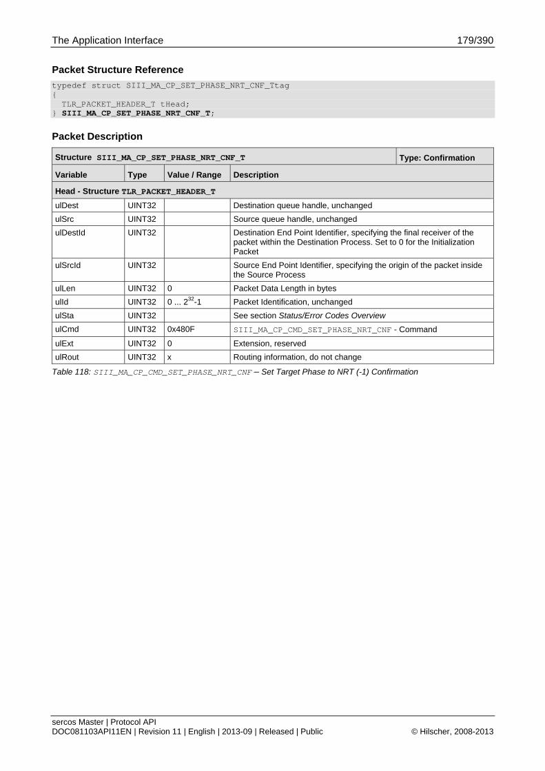
The Application Interface 179/390
sercos Master | Protocol API DOC081103API11EN | Revision 11 | English | 2013-09 | Released | Public © Hilscher, 2008-2013
Packet Structure Reference
typedef struct SIII_MA_CP_SET_PHASE_NRT_CNF_Ttag { TLR_PACKET_HEADER_T tHead;
} SIII_MA_CP_SET_PHASE_NRT_CNF_T;
Packet Description
Structure SIII_MA_CP_SET_PHASE_NRT_CNF_T Type: Confirmation
Variable Type Value / Range Description
Head - Structure TLR_PACKET_HEADER_T
ulDest UINT32 Destination queue handle, unchanged
ulSrc UINT32 Source queue handle, unchanged
ulDestId UINT32 Destination End Point Identifier, specifying the final receiver of the packet within the Destination Process. Set to 0 for the Initialization Packet
ulSrcId UINT32 Source End Point Identifier, specifying the origin of the packet inside the Source Process
ulLen UINT32 0 Packet Data Length in bytes
ulId UINT32 0 ... 232-1 Packet Identification, unchanged
ulSta UINT32 See section Status/Error Codes Overview
ulCmd UINT32 0x480F SIII_MA_CP_CMD_SET_PHASE_NRT_CNF - Command
ulExt UINT32 0 Extension, reserved
ulRout UINT32 x Routing information, do not change
Table 118: SIII_MA_CP_CMD_SET_PHASE_NRT_CNF – Set Target Phase to NRT (-1) Confirmation
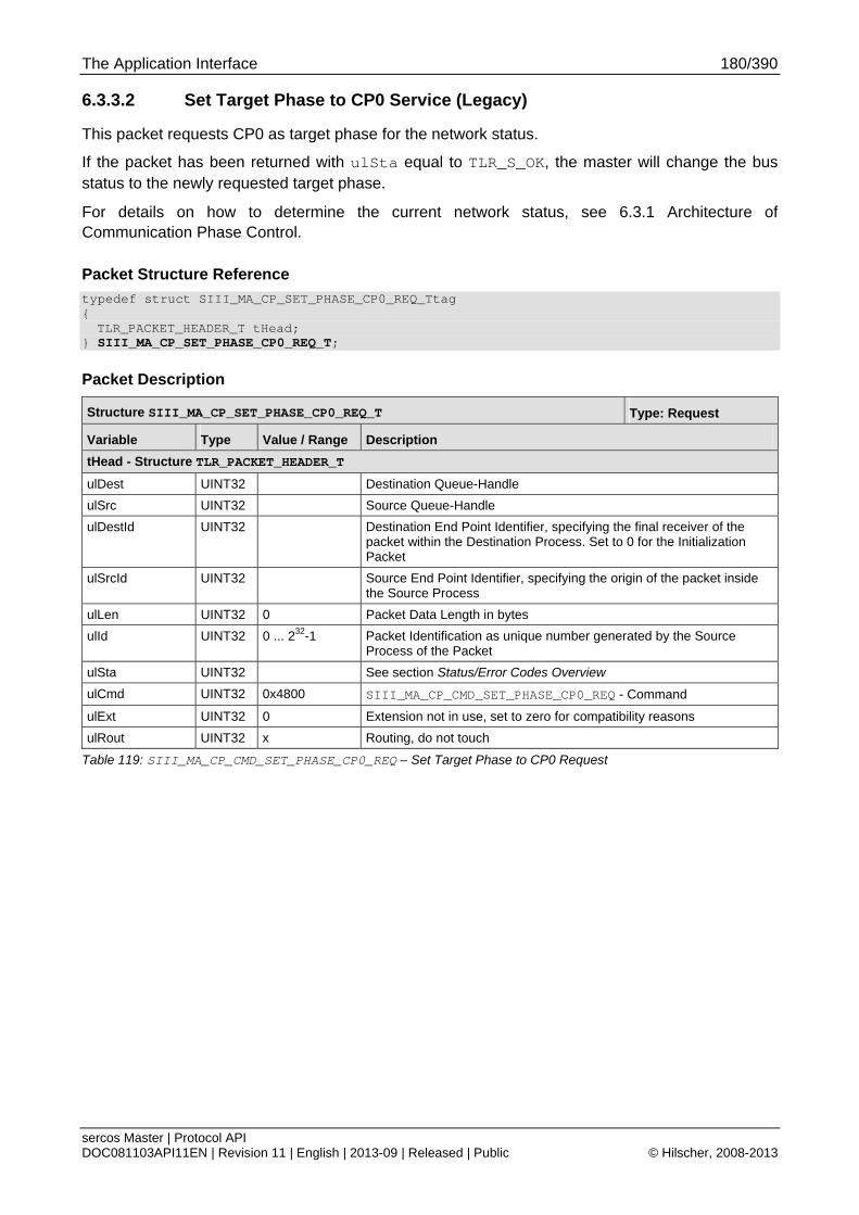
The Application Interface 180/390
sercos Master | Protocol API DOC081103API11EN | Revision 11 | English | 2013-09 | Released | Public © Hilscher, 2008-2013
6.3.3.2 Set Target Phase to CP0 Service (Legacy)
This packet requests CP0 as target phase for the network status.
If the packet has been returned with ulSta equal to TLR_S_OK, the master will change the bus status to the newly requested target phase.
For details on how to determine the current network status, see 6.3.1 Architecture of Communication Phase Control.
Packet Structure Reference
typedef struct SIII_MA_CP_SET_PHASE_CP0_REQ_Ttag { TLR_PACKET_HEADER_T tHead;
} SIII_MA_CP_SET_PHASE_CP0_REQ_T;
Packet Description
Structure SIII_MA_CP_SET_PHASE_CP0_REQ_T Type: Request
Variable Type Value / Range Description
tHead - Structure TLR_PACKET_HEADER_T
ulDest UINT32 Destination Queue-Handle
ulSrc UINT32 Source Queue-Handle
ulDestId UINT32 Destination End Point Identifier, specifying the final receiver of the packet within the Destination Process. Set to 0 for the Initialization Packet
ulSrcId UINT32 Source End Point Identifier, specifying the origin of the packet inside the Source Process
ulLen UINT32 0 Packet Data Length in bytes
ulId UINT32 0 ... 232-1 Packet Identification as unique number generated by the Source Process of the Packet
ulSta UINT32 See section Status/Error Codes Overview
ulCmd UINT32 0x4800 SIII_MA_CP_CMD_SET_PHASE_CP0_REQ - Command
ulExt UINT32 0 Extension not in use, set to zero for compatibility reasons
ulRout UINT32 x Routing, do not touch
Table 119: SIII_MA_CP_CMD_SET_PHASE_CP0_REQ – Set Target Phase to CP0 Request
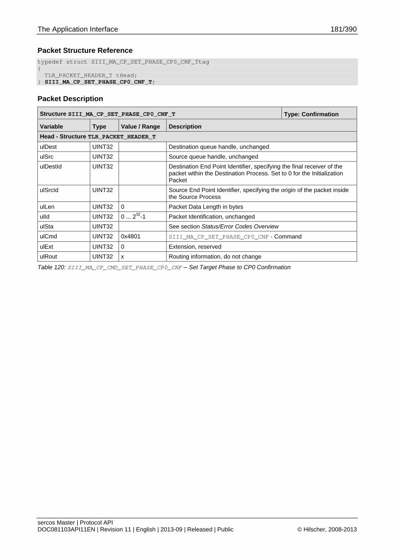
The Application Interface 181/390
sercos Master | Protocol API DOC081103API11EN | Revision 11 | English | 2013-09 | Released | Public © Hilscher, 2008-2013
Packet Structure Reference
typedef struct SIII_MA_CP_SET_PHASE_CP0_CNF_Ttag { TLR_PACKET_HEADER_T tHead;
} SIII_MA_CP_SET_PHASE_CP0_CNF_T;
Packet Description
Structure SIII_MA_CP_SET_PHASE_CP0_CNF_T Type: Confirmation
Variable Type Value / Range Description
Head - Structure TLR_PACKET_HEADER_T
ulDest UINT32 Destination queue handle, unchanged
ulSrc UINT32 Source queue handle, unchanged
ulDestId UINT32 Destination End Point Identifier, specifying the final receiver of the packet within the Destination Process. Set to 0 for the Initialization Packet
ulSrcId UINT32 Source End Point Identifier, specifying the origin of the packet inside the Source Process
ulLen UINT32 0 Packet Data Length in bytes
ulId UINT32 0 ... 232-1 Packet Identification, unchanged
ulSta UINT32 See section Status/Error Codes Overview
ulCmd UINT32 0x4801 SIII_MA_CP_SET_PHASE_CP0_CNF - Command
ulExt UINT32 0 Extension, reserved
ulRout UINT32 x Routing information, do not change
Table 120: SIII_MA_CP_CMD_SET_PHASE_CP0_CNF – Set Target Phase to CP0 Confirmation

The Application Interface 182/390
sercos Master | Protocol API DOC081103API11EN | Revision 11 | English | 2013-09 | Released | Public © Hilscher, 2008-2013
6.3.3.3 Set Target Phase to CP1 Service (Legacy)
This packet requests CP1 as target phase for the network status. If the packet has been returned with ulSta equal to TLR_S_OK, the master will change the bus status to the newly requested target phase.
For details on how to determine the current network status, see 6.3.1 Architecture of Communication Phase Control.
Packet Structure Reference
typedef struct SIII_MA_CP_SET_PHASE_CP1_REQ_Ttag { TLR_PACKET_HEADER_T tHead;
} SIII_MA_CP_SET_PHASE_CP1_REQ_T;
Packet Description
Structure SIII_MA_CP_SET_PHASE_CP1_REQ_T Type: Request
Variable Type Value / Range Description
tHead - Structure TLR_PACKET_HEADER_T
ulDest UINT32 Destination Queue-Handle
ulSrc UINT32 Source Queue-Handle
ulDestId UINT32 Destination End Point Identifier, specifying the final receiver of the packet within the Destination Process. Set to 0 for the Initialization Packet
ulSrcId UINT32 Source End Point Identifier, specifying the origin of the packet inside the Source Process
ulLen UINT32 0 Packet Data Length in bytes
ulId UINT32 0 ... 232-1 Packet Identification as unique number generated by the Source Process of the Packet
ulSta UINT32 See section Status/Error Codes Overview
ulCmd UINT32 0x4802 SIII_MA_CP_CMD_SET_PHASE_CP1_REQ - Command
ulExt UINT32 0 Extension not in use, set to zero for compatibility reasons
ulRout UINT32 x Routing, do not touch
Table 121: SIII_MA_CP_CMD_SET_PHASE_CP1_REQ – Set Target Phase to CP1 Request
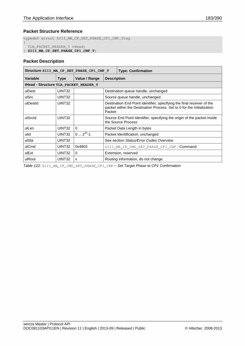
The Application Interface 183/390
sercos Master | Protocol API DOC081103API11EN | Revision 11 | English | 2013-09 | Released | Public © Hilscher, 2008-2013
Packet Structure Reference
typedef struct SIII_MA_CP_SET_PHASE_CP1_CNF_Ttag { TLR_PACKET_HEADER_T tHead;
} SIII_MA_CP_SET_PHASE_CP1_CNF_T;
Packet Description
Structure SIII_MA_CP_SET_PHASE_CP1_CNF_T Type: Confirmation
Variable Type Value / Range Description
tHead - Structure TLR_PACKET_HEADER_T
ulDest UINT32 Destination queue handle, unchanged
ulSrc UINT32 Source queue handle, unchanged
ulDestId UINT32 Destination End Point Identifier, specifying the final receiver of the packet within the Destination Process. Set to 0 for the Initialization Packet
ulSrcId UINT32 Source End Point Identifier, specifying the origin of the packet inside the Source Process
ulLen UINT32 0 Packet Data Length in bytes
ulId UINT32 0 ... 232-1 Packet Identification, unchanged
ulSta UINT32 See section Status/Error Codes Overview
ulCmd UINT32 0x4803 SIII_MA_CP_CMD_SET_PHASE_CP1_CNF - Command
ulExt UINT32 0 Extension, reserved
ulRout UINT32 x Routing information, do not change
Table 122: SIII_MA_CP_CMD_SET_PHASE_CP1_CNF – Set Target Phase to CP1 Confirmation

The Application Interface 184/390
sercos Master | Protocol API DOC081103API11EN | Revision 11 | English | 2013-09 | Released | Public © Hilscher, 2008-2013
6.3.3.4 Set Target Phase to CP2 Service (Legacy)
This packet requests CP2 as target phase for the network status. If the packet has been returned with ulSta equal to TLR_S_OK, the master will change the bus status to the newly requested target phase.
For details on how to determine the current network status, see 6.3.1 Architecture of Communication Phase Control.
Packet Structure Reference
typedef struct SIII_MA_CP_SET_PHASE_CP2_REQ_Ttag { TLR_PACKET_HEADER_T tHead;
} SIII_MA_CP_SET_PHASE_CP2_REQ_T;
Packet Description
Structure SIII_MA_CP_SET_PHASE_CP2_REQ_T Type: Request
Variable Type Value / Range Description
tHead - Structure TLR_PACKET_HEADER_T
ulDest UINT32 Destination Queue-Handle
ulSrc UINT32 Source Queue-Handle
ulDestId UINT32 Destination End Point Identifier, specifying the final receiver of the packet within the Destination Process. Set to 0 for the Initialization Packet
ulSrcId UINT32 Source End Point Identifier, specifying the origin of the packet inside the Source Process
ulLen UINT32 0 Packet Data Length in bytes
ulId UINT32 0 ... 232-1 Packet Identification as unique number generated by the Source Process of the Packet
ulSta UINT32 See section Status/Error Codes Overview
ulCmd UINT32 0x4804 SIII_MA_CP_CMD_SET_PHASE_CP2_REQ - Command
ulExt UINT32 0 Extension not in use, set to zero for compatibility reasons
ulRout UINT32 x Routing, do not touch
Table 123: SIII_MA_CP_CMD_SET_PHASE_CP2_REQ – Set Target Phase to CP2 Request

The Application Interface 185/390
sercos Master | Protocol API DOC081103API11EN | Revision 11 | English | 2013-09 | Released | Public © Hilscher, 2008-2013
Packet Structure Reference
typedef struct SIII_MA_CP_SET_PHASE_CP2_CNF_Ttag { TLR_PACKET_HEADER_T tHead;
} SIII_MA_CP_SET_PHASE_CP2_CNF_T;
Packet Description
Structure SIII_MA_CP_SET_PHASE_CP2_CNF_T Type: Confirmation
Variable Type Value / Range Description
Head - Structure TLR_PACKET_HEADER_T
ulDest UINT32 Destination queue handle, unchanged
ulSrc UINT32 Source queue handle, unchanged
ulDestId UINT32 Destination End Point Identifier, specifying the final receiver of the packet within the Destination Process. Set to 0 for the Initialization Packet
ulSrcId UINT32 Source End Point Identifier, specifying the origin of the packet inside the Source Process
ulLen UINT32 0 Packet Data Length in bytes
ulId UINT32 0 ... 232-1 Packet Identification, unchanged
ulSta UINT32 See section Status/Error Codes Overview
ulCmd UINT32 0x4805 SIII_MA_CP_CMD_SET_PHASE_CP2_CNF - Command
ulExt UINT32 0 Extension, reserved
ulRout UINT32 x Routing information, do not change
Table 124: SIII_MA_CP_CMD_SET_PHASE_CP2_CNF – Set Target Phase to CP2 Confirmation
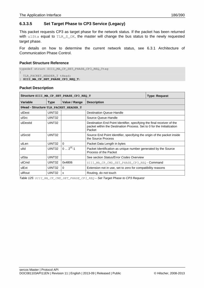
The Application Interface 186/390
sercos Master | Protocol API DOC081103API11EN | Revision 11 | English | 2013-09 | Released | Public © Hilscher, 2008-2013
6.3.3.5 Set Target Phase to CP3 Service (Legacy)
This packet requests CP3 as target phase for the network status. If the packet has been returned with ulSta equal to TLR_S_OK, the master will change the bus status to the newly requested target phase.
For details on how to determine the current network status, see 6.3.1 Architecture of Communication Phase Control.
Packet Structure Reference
typedef struct SIII_MA_CP_SET_PHASE_CP3_REQ_Ttag { TLR_PACKET_HEADER_T tHead;
} SIII_MA_CP_SET_PHASE_CP3_REQ_T;
Packet Description
Structure SIII_MA_CP_SET_PHASE_CP3_REQ_T Type: Request
Variable Type Value / Range Description
tHead - Structure TLR_PACKET_HEADER_T
ulDest UINT32 Destination Queue-Handle
ulSrc UINT32 Source Queue-Handle
ulDestId UINT32 Destination End Point Identifier, specifying the final receiver of the packet within the Destination Process. Set to 0 for the Initialization Packet
ulSrcId UINT32 Source End Point Identifier, specifying the origin of the packet inside the Source Process
ulLen UINT32 0 Packet Data Length in bytes
ulId UINT32 0 ... 232-1 Packet Identification as unique number generated by the Source Process of the Packet
ulSta UINT32 See section Status/Error Codes Overview
ulCmd UINT32 0x4806 SIII_MA_CP_CMD_SET_PHASE_CP3_REQ - Command
ulExt UINT32 0 Extension not in use, set to zero for compatibility reasons
ulRout UINT32 x Routing, do not touch
Table 125: SIII_MA_CP_CMD_SET_PHASE_CP3_REQ – Set Target Phase to CP3 Request

The Application Interface 187/390
sercos Master | Protocol API DOC081103API11EN | Revision 11 | English | 2013-09 | Released | Public © Hilscher, 2008-2013
Packet Structure Reference
typedef struct SIII_MA_CP_SET_PHASE_CP3_CNF_Ttag { TLR_PACKET_HEADER_T tHead;
} SIII_MA_CP_SET_PHASE_CP3_CNF_T;
Packet Description
Structure SIII_MA_CP_SET_PHASE_CP3_CNF_T Type: Confirmation
Variable Type Value / Range Description
tHead - Structure TLR_PACKET_HEADER_T
ulDest UINT32 Destination queue handle, unchanged
ulSrc UINT32 Source queue handle, unchanged
ulDestId UINT32 Destination End Point Identifier, specifying the final receiver of the packet within the Destination Process. Set to 0 for the Initialization Packet
ulSrcId UINT32 Source End Point Identifier, specifying the origin of the packet inside the Source Process
ulLen UINT32 0 Packet Data Length in bytes
ulId UINT32 0 ... 232-1 Packet Identification, unchanged
ulSta UINT32 See section Status/Error Codes Overview
ulCmd UINT32 0x4807 SIII_MA_CP_CMD_SET_PHASE_CP3_CNF - Command
ulExt UINT32 0 Extension, reserved
ulRout UINT32 x Routing information, do not change
Table 126: SIII_MA_CP_CMD_SET_PHASE_CP3_CNF – Set Target Phase to CP3 Confirmation
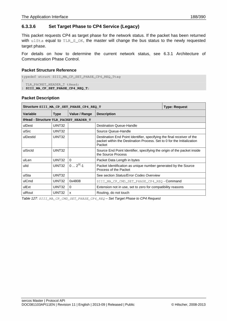
The Application Interface 188/390
sercos Master | Protocol API DOC081103API11EN | Revision 11 | English | 2013-09 | Released | Public © Hilscher, 2008-2013
6.3.3.6 Set Target Phase to CP4 Service (Legacy)
This packet requests CP4 as target phase for the network status. If the packet has been returned with ulSta equal to TLR_S_OK, the master will change the bus status to the newly requested target phase.
For details on how to determine the current network status, see 6.3.1 Architecture of Communication Phase Control.
Packet Structure Reference
typedef struct SIII_MA_CP_SET_PHASE_CP4_REQ_Ttag { TLR_PACKET_HEADER_T tHead;
} SIII_MA_CP_SET_PHASE_CP4_REQ_T;
Packet Description
Structure SIII_MA_CP_SET_PHASE_CP4_REQ_T Type: Request
Variable Type Value / Range Description
tHead - Structure TLR_PACKET_HEADER_T
ulDest UINT32 Destination Queue-Handle
ulSrc UINT32 Source Queue-Handle
ulDestId UINT32 Destination End Point Identifier, specifying the final receiver of the packet within the Destination Process. Set to 0 for the Initialization Packet
ulSrcId UINT32 Source End Point Identifier, specifying the origin of the packet inside the Source Process
ulLen UINT32 0 Packet Data Length in bytes
ulId UINT32 0 ... 232-1 Packet Identification as unique number generated by the Source Process of the Packet
ulSta UINT32 See section Status/Error Codes Overview
ulCmd UINT32 0x4808 SIII_MA_CP_CMD_SET_PHASE_CP4_REQ - Command
ulExt UINT32 0 Extension not in use, set to zero for compatibility reasons
ulRout UINT32 x Routing, do not touch
Table 127: SIII_MA_CP_CMD_SET_PHASE_CP4_REQ – Set Target Phase to CP4 Request

The Application Interface 189/390
sercos Master | Protocol API DOC081103API11EN | Revision 11 | English | 2013-09 | Released | Public © Hilscher, 2008-2013
Packet Structure Reference
typedef struct SIII_MA_CP_SET_PHASE_CP4_CNF_Ttag { TLR_PACKET_HEADER_T tHead;
} SIII_MA_CP_SET_PHASE_CP4_CNF_T;
Packet Description
Structure SIII_MA_CP_SET_PHASE_CP4_CNF_T Type: Confirmation
Variable Type Value / Range Description
Head - Structure TLR_PACKET_HEADER_T
ulDest UINT32 Destination queue handle, unchanged
ulSrc UINT32 Source queue handle, unchanged
ulDestId UINT32 Destination End Point Identifier, specifying the final receiver of the packet within the Destination Process. Set to 0 for the Initialization Packet
ulSrcId UINT32 Source End Point Identifier, specifying the origin of the packet inside the Source Process
ulLen UINT32 0 Packet Data Length in bytes
ulId UINT32 0 ... 232-1 Packet Identification, unchanged
ulSta UINT32 See section Status/Error Codes Overview
ulCmd UINT32 0x4809 SIII_MA_CP_CMD_SET_PHASE_CP4_CNF - Command
ulExt UINT32 0 Extension, reserved
ulRout UINT32 x Routing information, do not change
Table 128: SIII_MA_CP_CMD_SET_PHASE_CP4_CNF – Set Target Phase to CP4 Confirmation
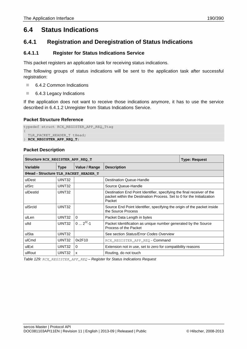
The Application Interface 190/390
sercos Master | Protocol API DOC081103API11EN | Revision 11 | English | 2013-09 | Released | Public © Hilscher, 2008-2013
6.4 Status Indications
6.4.1 Registration and Deregistration of Status Indications
6.4.1.1 Register for Status Indications Service
This packet registers an application task for receiving status indications.
The following groups of status indications will be sent to the application task after successful registration:
6.4.2 Common Indications
6.4.3 Legacy Indications
If the application does not want to receive those indications anymore, it has to use the service described in 6.4.1.2 Unregister from Status Indications Service.
Packet Structure Reference
typedef struct RCX_REGISTER_APP_REQ_Ttag { TLR_PACKET_HEADER_T tHead;
} RCX_REGISTER_APP_REQ_T;
Packet Description
Structure RCX_REGISTER_APP_REQ_T Type: Request
Variable Type Value / Range Description
tHead - Structure TLR_PACKET_HEADER_T
ulDest UINT32 Destination Queue-Handle
ulSrc UINT32 Source Queue-Handle
ulDestId UINT32 Destination End Point Identifier, specifying the final receiver of the packet within the Destination Process. Set to 0 for the Initialization Packet
ulSrcId UINT32 Source End Point Identifier, specifying the origin of the packet inside the Source Process
ulLen UINT32 0 Packet Data Length in bytes
ulId UINT32 0 ... 232-1 Packet Identification as unique number generated by the Source Process of the Packet
ulSta UINT32 See section Status/Error Codes Overview
ulCmd UINT32 0x2F10 RCX_REGISTER_APP_REQ - Command
ulExt UINT32 0 Extension not in use, set to zero for compatibility reasons
ulRout UINT32 x Routing, do not touch
Table 129: RCX_REGISTER_APP_REQ – Register for Status Indications Request
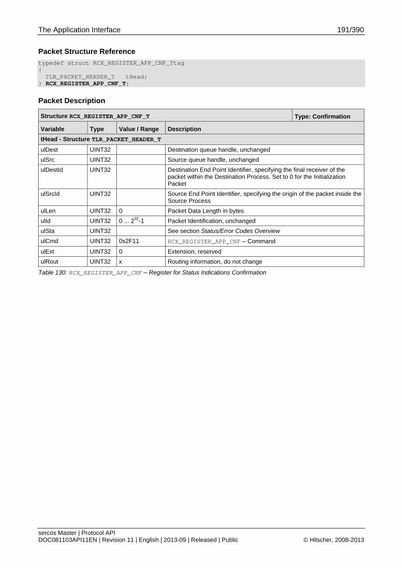
The Application Interface 191/390
sercos Master | Protocol API DOC081103API11EN | Revision 11 | English | 2013-09 | Released | Public © Hilscher, 2008-2013
Packet Structure Reference
typedef struct RCX_REGISTER_APP_CNF_Ttag { TLR_PACKET_HEADER_T tHead;
} RCX_REGISTER_APP_CNF_T;
Packet Description
Structure RCX_REGISTER_APP_CNF_T Type: Confirmation
Variable Type Value / Range Description
tHead - Structure TLR_PACKET_HEADER_T
ulDest UINT32 Destination queue handle, unchanged
ulSrc UINT32 Source queue handle, unchanged
ulDestId UINT32 Destination End Point Identifier, specifying the final receiver of the packet within the Destination Process. Set to 0 for the Initialization Packet
ulSrcId UINT32 Source End Point Identifier, specifying the origin of the packet inside the Source Process
ulLen UINT32 0 Packet Data Length in bytes
ulId UINT32 0 ... 232-1 Packet Identification, unchanged
ulSta UINT32 See section Status/Error Codes Overview
ulCmd UINT32 0x2F11 RCX_REGISTER_APP_CNF – Command
ulExt UINT32 0 Extension, reserved
ulRout UINT32 x Routing information, do not change
Table 130: RCX_REGISTER_APP_CNF – Register for Status Indications Confirmation
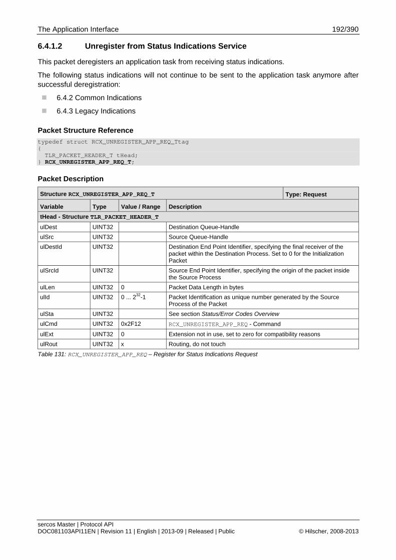
The Application Interface 192/390
sercos Master | Protocol API DOC081103API11EN | Revision 11 | English | 2013-09 | Released | Public © Hilscher, 2008-2013
6.4.1.2 Unregister from Status Indications Service
This packet deregisters an application task from receiving status indications.
The following status indications will not continue to be sent to the application task anymore after successful deregistration:
6.4.2 Common Indications
6.4.3 Legacy Indications
Packet Structure Reference
typedef struct RCX_UNREGISTER_APP_REQ_Ttag { TLR_PACKET_HEADER_T tHead;
} RCX_UNREGISTER_APP_REQ_T;
Packet Description
Structure RCX_UNREGISTER_APP_REQ_T Type: Request
Variable Type Value / Range Description
tHead - Structure TLR_PACKET_HEADER_T
ulDest UINT32 Destination Queue-Handle
ulSrc UINT32 Source Queue-Handle
ulDestId UINT32 Destination End Point Identifier, specifying the final receiver of the packet within the Destination Process. Set to 0 for the Initialization Packet
ulSrcId UINT32 Source End Point Identifier, specifying the origin of the packet inside the Source Process
ulLen UINT32 0 Packet Data Length in bytes
ulId UINT32 0 ... 232-1 Packet Identification as unique number generated by the Source Process of the Packet
ulSta UINT32 See section Status/Error Codes Overview
ulCmd UINT32 0x2F12 RCX_UNREGISTER_APP_REQ - Command
ulExt UINT32 0 Extension not in use, set to zero for compatibility reasons
ulRout UINT32 x Routing, do not touch
Table 131: RCX_UNREGISTER_APP_REQ – Register for Status Indications Request

The Application Interface 193/390
sercos Master | Protocol API DOC081103API11EN | Revision 11 | English | 2013-09 | Released | Public © Hilscher, 2008-2013
Packet Structure Reference
typedef struct RCX_UNREGISTER_APP_CNF_Ttag { TLR_PACKET_HEADER_T tHead;
} RCX_UNREGISTER_APP_CNF_T;
Packet Description
Structure RCX_UNREGISTER_APP_CNF_T Type: Confirmation
Variable Type Value / Range Description
tHead - Structure TLR_PACKET_HEADER_T
ulDest UINT32 Destination queue handle, unchanged
ulSrc UINT32 Source queue handle, unchanged
ulDestId UINT32 Destination End Point Identifier, specifying the final receiver of the packet within the Destination Process. Set to 0 for the Initialization Packet
ulSrcId UINT32 Source End Point Identifier, specifying the origin of the packet inside the Source Process
ulLen UINT32 0 Packet Data Length in bytes
ulId UINT32 0 ... 232-1 Packet Identification, unchanged
ulSta UINT32 See section Status/Error Codes Overview
ulCmd UINT32 0x2F13 RCX_UNREGISTER_APP_CNF – Command
ulExt UINT32 0 Extension, reserved
ulRout UINT32 x Routing information, do not change
Table 132: RCX_UNREGISTER_APP_CNF – Register for Status Indications Confirmation

The Application Interface 194/390
sercos Master | Protocol API DOC081103API11EN | Revision 11 | English | 2013-09 | Released | Public © Hilscher, 2008-2013
6.4.1.3 Select Active Indications Service (since V2.1.X)
This service configures which indications will be sent to a registered application.
Indication Flags
Note: Bits that are not defined have to be set to zero.
Field Index Bit Number Definition / Description Default Configuration
0 0 MSK_SIII_MA_CP_IND_0_FLAG_OLD_PHASE
Enable old phase indications
see 6.4.3 Legacy Indications
Enabled
0 1 MSK_SIII_MA_CP_IND_0_FLAG_NEW_PHASE
Enable new phase indications
see 6.4.2.1 Current Communication Phase Indication (since V2.1.X)
Enabled
0 2 MSK_SIII_MA_CP_IND_0_FLAG_STATE_CHG_STOPPED
Enable State Change Stopped indications
see 6.4.2.3 Network Phase Change Aborted Indication
Enabled
0 3 MSK_SIII_MA_CP_IND_0_FLAG_C1D_DIAGNOSTICS
Enable C1D Diagnostic indications
see 6.4.2.4 C1D Error Changed Indication
Enabled
0 4 MSK_SIII_MA_CP_IND_0_FLAG_C2D_DIAGNOSTICS
Enable C2D Diagnostic indications
see 6.4.2.5 C2D Warning Changed Indication
Enabled
0 6 MSK_SIII_MA_CP_IND_0_FLAG_SLAVES_VALID
Enable Slaves Valid indications
see 6.4.2.2 Slaves Valid Indication Service (since V2.1.X)
Enabled
0 7 MSK_SIII_MA_CP_IND_0_FLAG_PCA
Enable Procedure Command Acknowledge Bit indications
see 6.4.2.6 PCA Bit Changed Indication (since V2.1.X)
Disabled
0 8 MSK_SIII_MA_CP_IND_0_FLAG_CP0_SLAVE_STATES
Enable CP0 Slave State indications
Enabled
Table 133: Configurable Indication Flags
Packet Structure Reference
#define SIII_MA_CP_NUM_SETS_OF_INDICATION_FLAGS 8 typedef struct SIII_MA_CP_SELECT_INDICATIONS_REQ_DATA_Ttag { TLR_UINT32 aulEnableIndicationFlags[SIII_MA_CP_NUM_SETS_OF_INDICATION_FLAGS]; TLR_UINT32 aulDisableIndicationFlags[SIII_MA_CP_NUM_SETS_OF_INDICATION_FLAGS]; TLR_BOOLEAN32 fReplaceEnabledFlags; } SIII_MA_CP_SELECT_INDICATIONS_REQ_DATA_T; typedef struct SIII_MA_CP_SELECT_INDICATIONS_REQ_Ttag { TLR_PACKET_HEADER_T tHead; SIII_MA_CP_SELECT_INDICATIONS_REQ_DATA_T tData; } SIII_MA_CP_SELECT_INDICATIONS_REQ_T;
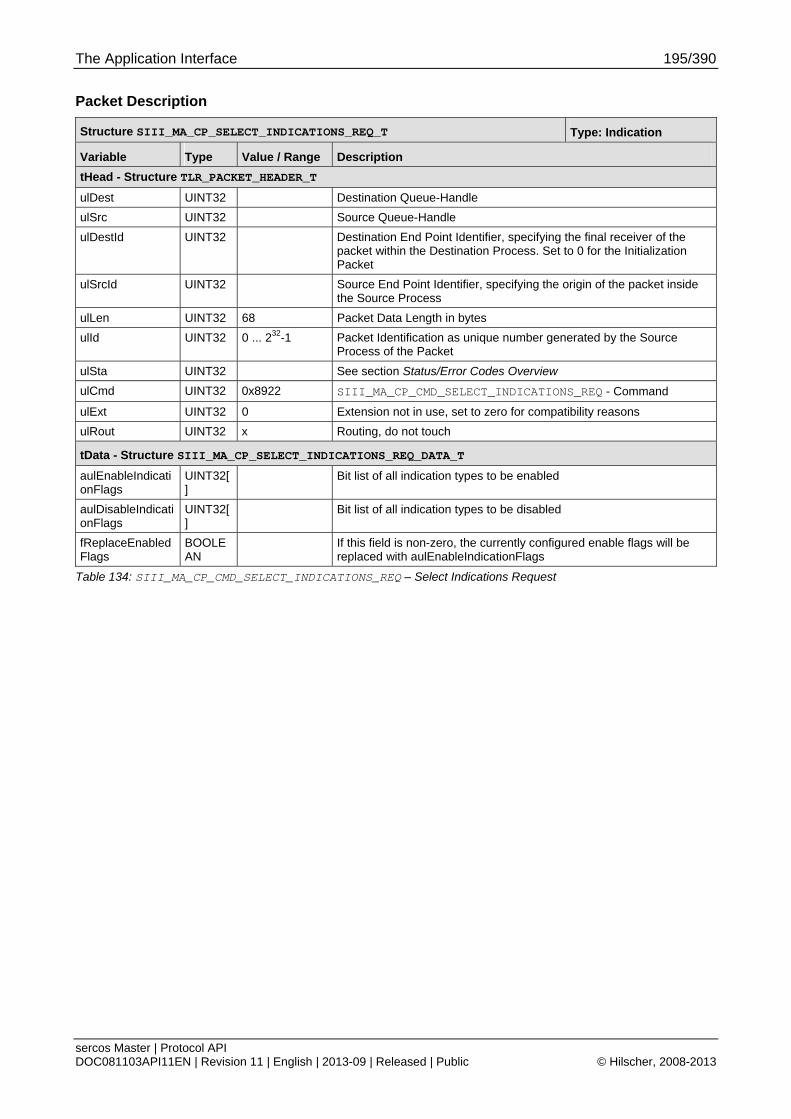
The Application Interface 195/390
sercos Master | Protocol API DOC081103API11EN | Revision 11 | English | 2013-09 | Released | Public © Hilscher, 2008-2013
Packet Description
Structure SIII_MA_CP_SELECT_INDICATIONS_REQ_T Type: Indication
Variable Type Value / Range Description
tHead - Structure TLR_PACKET_HEADER_T
ulDest UINT32 Destination Queue-Handle
ulSrc UINT32 Source Queue-Handle
ulDestId UINT32 Destination End Point Identifier, specifying the final receiver of the packet within the Destination Process. Set to 0 for the Initialization Packet
ulSrcId UINT32 Source End Point Identifier, specifying the origin of the packet inside the Source Process
ulLen UINT32 68 Packet Data Length in bytes
ulId UINT32 0 ... 232-1 Packet Identification as unique number generated by the Source Process of the Packet
ulSta UINT32 See section Status/Error Codes Overview
ulCmd UINT32 0x8922 SIII_MA_CP_CMD_SELECT_INDICATIONS_REQ - Command
ulExt UINT32 0 Extension not in use, set to zero for compatibility reasons
ulRout UINT32 x Routing, do not touch
tData - Structure SIII_MA_CP_SELECT_INDICATIONS_REQ_DATA_T
aulEnableIndicationFlags
UINT32[]
Bit list of all indication types to be enabled
aulDisableIndicationFlags
UINT32[]
Bit list of all indication types to be disabled
fReplaceEnabledFlags
BOOLEAN
If this field is non-zero, the currently configured enable flags will be replaced with aulEnableIndicationFlags
Table 134: SIII_MA_CP_CMD_SELECT_INDICATIONS_REQ – Select Indications Request
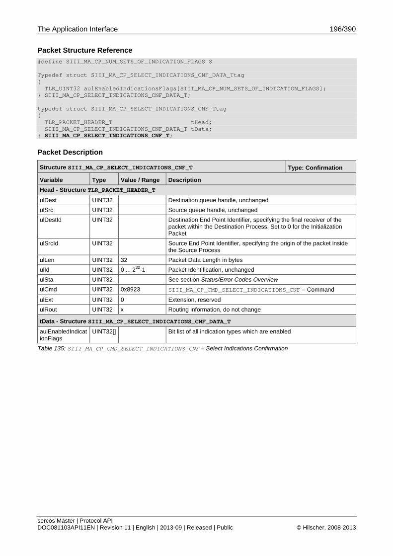
The Application Interface 196/390
sercos Master | Protocol API DOC081103API11EN | Revision 11 | English | 2013-09 | Released | Public © Hilscher, 2008-2013
Packet Structure Reference
#define SIII_MA_CP_NUM_SETS_OF_INDICATION_FLAGS 8 Typedef struct SIII_MA_CP_SELECT_INDICATIONS_CNF_DATA_Ttag { TLR_UINT32 aulEnabledIndicationsFlags[SIII_MA_CP_NUM_SETS_OF_INDICATION_FLAGS]; } SIII_MA_CP_SELECT_INDICATIONS_CNF_DATA_T; typedef struct SIII_MA_CP_SELECT_INDICATIONS_CNF_Ttag { TLR_PACKET_HEADER_T tHead; SIII_MA_CP_SELECT_INDICATIONS_CNF_DATA_T tData; } SIII_MA_CP_SELECT_INDICATIONS_CNF_T;
Packet Description
Structure SIII_MA_CP_SELECT_INDICATIONS_CNF_T Type: Confirmation
Variable Type Value / Range Description
Head - Structure TLR_PACKET_HEADER_T
ulDest UINT32 Destination queue handle, unchanged
ulSrc UINT32 Source queue handle, unchanged
ulDestId UINT32 Destination End Point Identifier, specifying the final receiver of the packet within the Destination Process. Set to 0 for the Initialization Packet
ulSrcId UINT32 Source End Point Identifier, specifying the origin of the packet inside the Source Process
ulLen UINT32 32 Packet Data Length in bytes
ulId UINT32 0 ... 232-1 Packet Identification, unchanged
ulSta UINT32 See section Status/Error Codes Overview
ulCmd UINT32 0x8923 SIII_MA_CP_CMD_SELECT_INDICATIONS_CNF – Command
ulExt UINT32 0 Extension, reserved
ulRout UINT32 x Routing information, do not change
tData - Structure SIII_MA_CP_SELECT_INDICATIONS_CNF_DATA_T
aulEnabledIndicationFlags
UINT32[] Bit list of all indication types which are enabled
Table 135: SIII_MA_CP_CMD_SELECT_INDICATIONS_CNF – Select Indications Confirmation
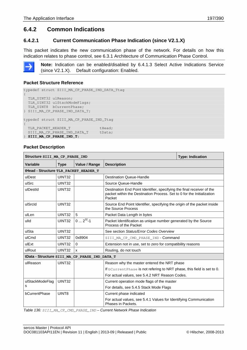
The Application Interface 197/390
sercos Master | Protocol API DOC081103API11EN | Revision 11 | English | 2013-09 | Released | Public © Hilscher, 2008-2013
6.4.2 Common Indications
6.4.2.1 Current Communication Phase Indication (since V2.1.X)
This packet indicates the new communication phase of the network. For details on how this indication relates to phase control, see 6.3.1 Architecture of Communication Phase Control.
Note: Indication can be enabled/disabled by 6.4.1.3 Select Active Indications Service (since V2.1.X). Default configuration: Enabled.
Packet Structure Reference
typedef struct SIII_MA_CP_PHASE_IND_DATA_Ttag { TLR_UINT32 ulReason; TLR_UINT32 ulStackModeFlags; TLR_UINT8 bCurrentPhase; } SIII_MA_CP_PHASE_IND_DATA_T; typedef struct SIII_MA_CP_PHASE_IND_Ttag { TLR_PACKET_HEADER_T tHead; SIII_MA_CP_PHASE_IND_DATA_T tData;
} SIII_MA_CP_PHASE_IND_T;
Packet Description
Structure SIII_MA_CP_PHASE_IND Type: Indication
Variable Type Value / Range Description
tHead - Structure TLR_PACKET_HEADER_T
ulDest UINT32 Destination Queue-Handle
ulSrc UINT32 Source Queue-Handle
ulDestId UINT32 Destination End Point Identifier, specifying the final receiver of the packet within the Destination Process. Set to 0 for the Initialization Packet
ulSrcId UINT32 Source End Point Identifier, specifying the origin of the packet inside the Source Process
ulLen UINT32 5 Packet Data Length in bytes
ulId UINT32 0 ... 232-1 Packet Identification as unique number generated by the Source Process of the Packet
ulSta UINT32 See section Status/Error Codes Overview
ulCmd UINT32 0x8904 SIII_MA_CP_CMD_PHASE_IND - Command
ulExt UINT32 0 Extension not in use, set to zero for compatibility reasons
ulRout UINT32 x Routing, do not touch
tData - Structure SIII_MA_CP_PHASE_IND_DATA_T
ulReason UINT32 Reason why the master entered the NRT phase
If bCurrentPhase is not refering to NRT phase, this field is set to 0.
For actual values, see 5.4.2 NRT Reason Codes.
ulStackModeFlags
UINT32 Current operation mode flags of the master
For details, see 5.4.5 Stack Mode Flags
bCurrentPhase UINT8 Current phase indicated
For actual values, see 5.4.1 Values for Identifying Communication Phases in Packets.
Table 136: SIII_MA_CP_CMD_PHASE_IND – Current Network Phase Indication

The Application Interface 198/390
sercos Master | Protocol API DOC081103API11EN | Revision 11 | English | 2013-09 | Released | Public © Hilscher, 2008-2013
Packet Structure Reference
typedef struct SIII_MA_CP_PHASE_RES_Ttag { TLR_PACKET_HEADER_T tHead; } SIII_MA_CP_PHASE_RES_T;
Packet Description
Structure SIII_MA_CP_PHASE_RES Type: Indication
Variable Type Value / Range Description
tHead - Structure TLR_PACKET_HEADER_T
ulDest UINT32 Destination Queue-Handle
ulSrc UINT32 Source Queue-Handle
ulDestId UINT32 Destination End Point Identifier, specifying the final receiver of the packet within the Destination Process. Set to 0 for the Initialization Packet
ulSrcId UINT32 Source End Point Identifier, specifying the origin of the packet inside the Source Process
ulLen UINT32 0 Packet Data Length in bytes
ulId UINT32 0 ... 232-1 Packet Identification as unique number generated by the Source Process of the Packet
ulSta UINT32 See section Status/Error Codes Overview
ulCmd UINT32 0x8905 SIII_MA_CP_CMD_PHASE_RES - Command
ulExt UINT32 0 Extension not in use, set to zero for compatibility reasons
ulRout UINT32 x Routing, do not touch
Table 137: SIII_MA_CP_CMD_PHASE_RES – Current Network Phase Response
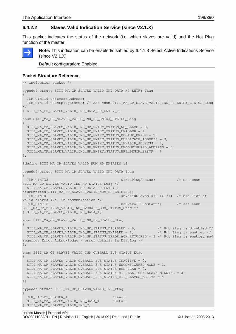
The Application Interface 199/390
sercos Master | Protocol API DOC081103API11EN | Revision 11 | English | 2013-09 | Released | Public © Hilscher, 2008-2013
6.4.2.2 Slaves Valid Indication Service (since V2.1.X)
This packet indicates the status of the network (i.e. which slaves are valid) and the Hot Plug function of the master.
Note: This indication can be enabled/disabled by 6.4.1.3 Select Active Indications Service (since V2.1.X)
Default configuration: Enabled.
Packet Structure Reference
/* indication packet */ typedef struct SIII_MA_CP_SLAVES_VALID_IND_DATA_HP_ENTRY_Ttag { TLR_UINT16 usSercosAddress; TLR_UINT16 usHotplugStatus; /* see enum SIII_MA_CP_SLAVE_VALID_IND_HP_ENTRY_STATUS_Etag */ } SIII_MA_CP_SLAVES_VALID_IND_DATA_HP_ENTRY_T; enum SIII_MA_CP_SLAVES_VALID_IND_HP_ENTRY_STATUS_Etag { SIII_MA_CP_SLAVES_VALID_IND_HP_ENTRY_STATUS_NO_SLAVE = 0, SIII_MA_CP_SLAVES_VALID_IND_HP_ENTRY_STATUS_ENABLED = 1, SIII_MA_CP_SLAVES_VALID_IND_HP_ENTRY_STATUS_BOOTUP_ERROR = 2, SIII_MA_CP_SLAVES_VALID_IND_HP_ENTRY_STATUS_DUPLICATE_ADDRESS = 3, SIII_MA_CP_SLAVES_VALID_IND_HP_ENTRY_STATUS_INVALID_ADDRESS = 4, SIII_MA_CP_SLAVES_VALID_IND_HP_ENTRY_STATUS_UNCONFIGURED_ADDRESS = 5, SIII_MA_CP_SLAVES_VALID_IND_HP_ENTRY_STATUS_HP1_BEGIN_ERROR = 6 }; #define SIII_MA_CP_SLAVES_VALID_NUM_HP_ENTRIES 16 typedef struct SIII_MA_CP_SLAVES_VALID_IND_DATA_Ttag { TLR_UINT32 ulHotPlugStatus; /* see enum SIII_MA_CP_SLAVES_VALID_IND_HP_STATUS_Etag */ SIII_MA_CP_SLAVES_VALID_IND_DATA_HP_ENTRY_T atHPEntries[SIII_MA_CP_SLAVES_VALID_NUM_HP_ENTRIES]; TLR_UINT8 abValidSlaves[512 >> 3]; /* bit list of valid slaves i.e. in communication */ TLR_UINT16 usOverallBusStatus; /* see enum SIII_MA_CP_SLAVES_VALID_IND_OVERALL_BUS_STATUS_Etag */ } SIII_MA_CP_SLAVES_VALID_IND_DATA_T; enum SIII_MA_CP_SLAVES_VALID_IND_HP_STATUS_Etag { SIII_MA_CP_SLAVES_VALID_IND_HP_STATUS_DISABLED = 0, /* Hot Plug is disabled */ SIII_MA_CP_SLAVES_VALID_IND_HP_STATUS_ENABLED = 1, /* Hot Plug is enabled */ SIII_MA_CP_SLAVES_VALID_IND_HP_STATUS_ERROR_ACK_REQUIRED = 2 /* Hot Plug is enabled and requires Error Acknowledge / error details in DiagLog */ }; enum SIII_MA_CP_SLAVES_VALID_IND_OVERALL_BUS_STATUS_Etag { SIII_MA_CP_SLAVES_VALID_OVERALL_BUS_STATUS_INACTIVE = 0, SIII_MA_CP_SLAVES_VALID_OVERALL_BUS_STATUS_UNCONFIGURED_MODE = 1, SIII_MA_CP_SLAVES_VALID_OVERALL_BUS_STATUS_BUS_SCAN = 2, SIII_MA_CP_SLAVES_VALID_OVERALL_BUS_STATUS_AT_LEAST_ONE_SLAVE_MISSING = 3, SIII_MA_CP_SLAVES_VALID_OVERALL_BUS_STATUS_ALL_SLAVES_ACTIVE = 4 }; typedef struct SIII_MA_CP_SLAVES_VALID_IND_Ttag { TLR_PACKET_HEADER_T tHead; SIII_MA_CP_SLAVES_VALID_IND_DATA_T tData; } SIII_MA_CP_SLAVES_VALID_IND_T;
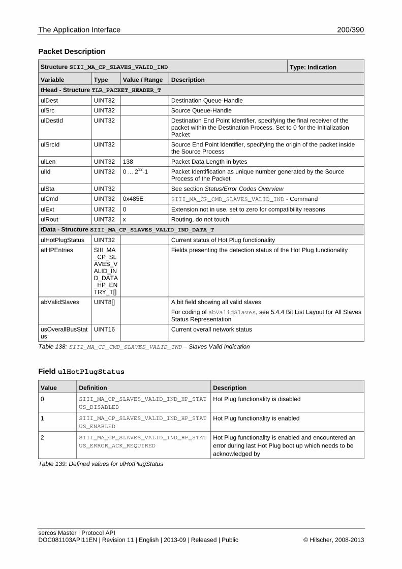
The Application Interface 200/390
sercos Master | Protocol API DOC081103API11EN | Revision 11 | English | 2013-09 | Released | Public © Hilscher, 2008-2013
Packet Description
Structure SIII_MA_CP_SLAVES_VALID_IND Type: Indication
Variable Type Value / Range Description
tHead - Structure TLR_PACKET_HEADER_T
ulDest UINT32 Destination Queue-Handle
ulSrc UINT32 Source Queue-Handle
ulDestId UINT32 Destination End Point Identifier, specifying the final receiver of the packet within the Destination Process. Set to 0 for the Initialization Packet
ulSrcId UINT32 Source End Point Identifier, specifying the origin of the packet inside the Source Process
ulLen UINT32 138 Packet Data Length in bytes
ulId UINT32 0 ... 232-1 Packet Identification as unique number generated by the Source Process of the Packet
ulSta UINT32 See section Status/Error Codes Overview
ulCmd UINT32 0x485E SIII_MA_CP_CMD_SLAVES_VALID_IND - Command
ulExt UINT32 0 Extension not in use, set to zero for compatibility reasons
ulRout UINT32 x Routing, do not touch
tData - Structure SIII_MA_CP_SLAVES_VALID_IND_DATA_T
ulHotPlugStatus UINT32 Current status of Hot Plug functionality
atHPEntries SIII_MA_CP_SLAVES_VALID_IND_DATA_HP_ENTRY_T[]
Fields presenting the detection status of the Hot Plug functionality
abValidSlaves UINT8[] A bit field showing all valid slaves
For coding of abValidSlaves, see 5.4.4 Bit List Layout for All Slaves Status Representation
usOverallBusStatus
UINT16 Current overall network status
Table 138: SIII_MA_CP_CMD_SLAVES_VALID_IND – Slaves Valid Indication
Field ulHotPlugStatus
Value Definition Description
0 SIII_MA_CP_SLAVES_VALID_IND_HP_STATUS_DISABLED
Hot Plug functionality is disabled
1 SIII_MA_CP_SLAVES_VALID_IND_HP_STATUS_ENABLED
Hot Plug functionality is enabled
2 SIII_MA_CP_SLAVES_VALID_IND_HP_STATUS_ERROR_ACK_REQUIRED
Hot Plug functionality is enabled and encountered an error during last Hot Plug boot up which needs to be acknowledged by
Table 139: Defined values for ulHotPlugStatus
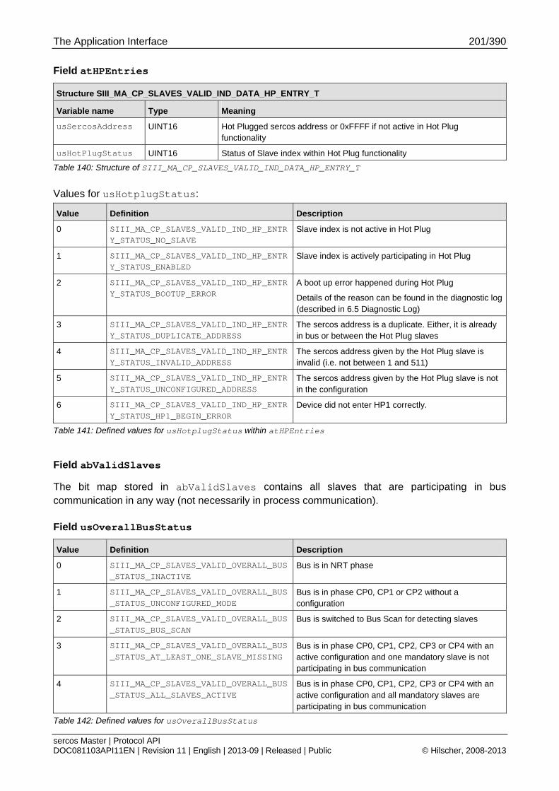
The Application Interface 201/390
sercos Master | Protocol API DOC081103API11EN | Revision 11 | English | 2013-09 | Released | Public © Hilscher, 2008-2013
Field atHPEntries
Structure SIII_MA_CP_SLAVES_VALID_IND_DATA_HP_ENTRY_T
Variable name Type Meaning
usSercosAddress UINT16 Hot Plugged sercos address or 0xFFFF if not active in Hot Plug functionality
usHotPlugStatus UINT16 Status of Slave index within Hot Plug functionality
Table 140: Structure of SIII_MA_CP_SLAVES_VALID_IND_DATA_HP_ENTRY_T
Values for usHotplugStatus:
Value Definition Description
0 SIII_MA_CP_SLAVES_VALID_IND_HP_ENTRY_STATUS_NO_SLAVE
Slave index is not active in Hot Plug
1 SIII_MA_CP_SLAVES_VALID_IND_HP_ENTRY_STATUS_ENABLED
Slave index is actively participating in Hot Plug
2 SIII_MA_CP_SLAVES_VALID_IND_HP_ENTRY_STATUS_BOOTUP_ERROR
A boot up error happened during Hot Plug
Details of the reason can be found in the diagnostic log (described in 6.5 Diagnostic Log)
3 SIII_MA_CP_SLAVES_VALID_IND_HP_ENTRY_STATUS_DUPLICATE_ADDRESS
The sercos address is a duplicate. Either, it is already in bus or between the Hot Plug slaves
4 SIII_MA_CP_SLAVES_VALID_IND_HP_ENTRY_STATUS_INVALID_ADDRESS
The sercos address given by the Hot Plug slave is invalid (i.e. not between 1 and 511)
5 SIII_MA_CP_SLAVES_VALID_IND_HP_ENTRY_STATUS_UNCONFIGURED_ADDRESS
The sercos address given by the Hot Plug slave is not in the configuration
6 SIII_MA_CP_SLAVES_VALID_IND_HP_ENTRY_STATUS_HP1_BEGIN_ERROR
Device did not enter HP1 correctly.
Table 141: Defined values for usHotplugStatus within atHPEntries
Field abValidSlaves
The bit map stored in abValidSlaves contains all slaves that are participating in bus communication in any way (not necessarily in process communication).
Field usOverallBusStatus
Value Definition Description
0 SIII_MA_CP_SLAVES_VALID_OVERALL_BUS_STATUS_INACTIVE
Bus is in NRT phase
1 SIII_MA_CP_SLAVES_VALID_OVERALL_BUS_STATUS_UNCONFIGURED_MODE
Bus is in phase CP0, CP1 or CP2 without a configuration
2 SIII_MA_CP_SLAVES_VALID_OVERALL_BUS_STATUS_BUS_SCAN
Bus is switched to Bus Scan for detecting slaves
3 SIII_MA_CP_SLAVES_VALID_OVERALL_BUS_STATUS_AT_LEAST_ONE_SLAVE_MISSING
Bus is in phase CP0, CP1, CP2, CP3 or CP4 with an active configuration and one mandatory slave is not participating in bus communication
4 SIII_MA_CP_SLAVES_VALID_OVERALL_BUS_STATUS_ALL_SLAVES_ACTIVE
Bus is in phase CP0, CP1, CP2, CP3 or CP4 with an active configuration and all mandatory slaves are participating in bus communication
Table 142: Defined values for usOverallBusStatus
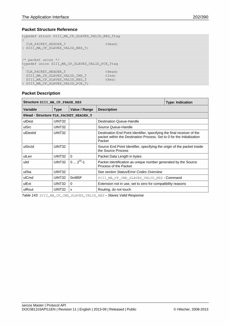
The Application Interface 202/390
sercos Master | Protocol API DOC081103API11EN | Revision 11 | English | 2013-09 | Released | Public © Hilscher, 2008-2013
Packet Structure Reference
typedef struct SIII_MA_CP_SLAVES_VALID_RES_Ttag { TLR_PACKET_HEADER_T tHead; } SIII_MA_CP_SLAVES_VALID_RES_T; /* packet union */ typedef union SIII_MA_CP_SLAVES_VALID_PCK_Ttag { TLR_PACKET_HEADER_T tHead; SIII_MA_CP_SLAVES_VALID_IND_T tInd; SIII_MA_CP_SLAVES_VALID_RES_T tRes; } SIII_MA_CP_SLAVES_VALID_PCK_T;
Packet Description
Structure SIII_MA_CP_PHASE_RES Type: Indication
Variable Type Value / Range Description
tHead - Structure TLR_PACKET_HEADER_T
ulDest UINT32 Destination Queue-Handle
ulSrc UINT32 Source Queue-Handle
ulDestId UINT32 Destination End Point Identifier, specifying the final receiver of the packet within the Destination Process. Set to 0 for the Initialization Packet
ulSrcId UINT32 Source End Point Identifier, specifying the origin of the packet inside the Source Process
ulLen UINT32 0 Packet Data Length in bytes
ulId UINT32 0 ... 232-1 Packet Identification as unique number generated by the Source Process of the Packet
ulSta UINT32 See section Status/Error Codes Overview
ulCmd UINT32 0x485F SIII_MA_CP_CMD_SLAVES_VALID_RES - Command
ulExt UINT32 0 Extension not in use, set to zero for compatibility reasons
ulRout UINT32 x Routing, do not touch
Table 143: SIII_MA_CP_CMD_SLAVES_VALID_RES – Slaves Valid Response
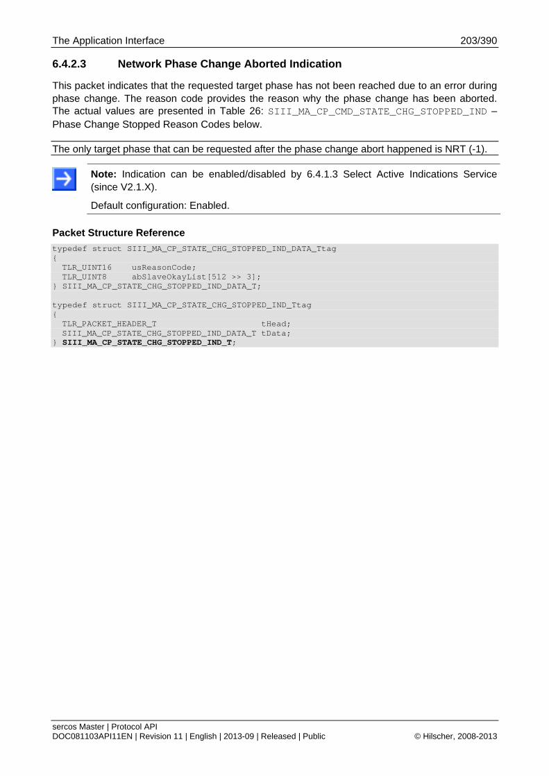
The Application Interface 203/390
sercos Master | Protocol API DOC081103API11EN | Revision 11 | English | 2013-09 | Released | Public © Hilscher, 2008-2013
6.4.2.3 Network Phase Change Aborted Indication
This packet indicates that the requested target phase has not been reached due to an error during phase change. The reason code provides the reason why the phase change has been aborted. The actual values are presented in Table 26: SIII_MA_CP_CMD_STATE_CHG_STOPPED_IND – Phase Change Stopped Reason Codes below.
The only target phase that can be requested after the phase change abort happened is NRT (-1).
Note: Indication can be enabled/disabled by 6.4.1.3 Select Active Indications Service (since V2.1.X).
Default configuration: Enabled.
Packet Structure Reference
typedef struct SIII_MA_CP_STATE_CHG_STOPPED_IND_DATA_Ttag { TLR_UINT16 usReasonCode; TLR_UINT8 abSlaveOkayList[512 >> 3];
} SIII_MA_CP_STATE_CHG_STOPPED_IND_DATA_T; typedef struct SIII_MA_CP_STATE_CHG_STOPPED_IND_Ttag { TLR_PACKET_HEADER_T tHead; SIII_MA_CP_STATE_CHG_STOPPED_IND_DATA_T tData;
} SIII_MA_CP_STATE_CHG_STOPPED_IND_T;
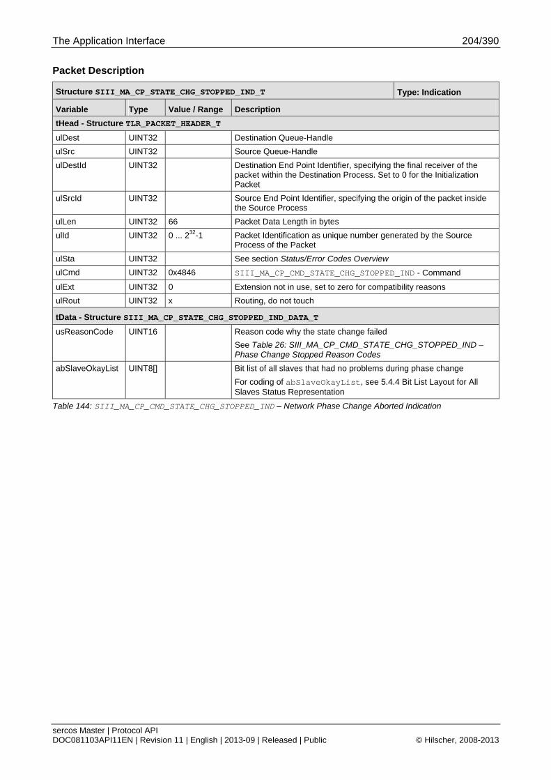
The Application Interface 204/390
sercos Master | Protocol API DOC081103API11EN | Revision 11 | English | 2013-09 | Released | Public © Hilscher, 2008-2013
Packet Description
Structure SIII_MA_CP_STATE_CHG_STOPPED_IND_T Type: Indication
Variable Type Value / Range Description
tHead - Structure TLR_PACKET_HEADER_T
ulDest UINT32 Destination Queue-Handle
ulSrc UINT32 Source Queue-Handle
ulDestId UINT32 Destination End Point Identifier, specifying the final receiver of the packet within the Destination Process. Set to 0 for the Initialization Packet
ulSrcId UINT32 Source End Point Identifier, specifying the origin of the packet inside the Source Process
ulLen UINT32 66 Packet Data Length in bytes
ulId UINT32 0 ... 232-1 Packet Identification as unique number generated by the Source Process of the Packet
ulSta UINT32 See section Status/Error Codes Overview
ulCmd UINT32 0x4846 SIII_MA_CP_CMD_STATE_CHG_STOPPED_IND - Command
ulExt UINT32 0 Extension not in use, set to zero for compatibility reasons
ulRout UINT32 x Routing, do not touch
tData - Structure SIII_MA_CP_STATE_CHG_STOPPED_IND_DATA_T
usReasonCode UINT16 Reason code why the state change failed
See Table 26: SIII_MA_CP_CMD_STATE_CHG_STOPPED_IND – Phase Change Stopped Reason Codes
abSlaveOkayList UINT8[] Bit list of all slaves that had no problems during phase change
For coding of abSlaveOkayList, see 5.4.4 Bit List Layout for All Slaves Status Representation
Table 144: SIII_MA_CP_CMD_STATE_CHG_STOPPED_IND – Network Phase Change Aborted Indication

The Application Interface 205/390
sercos Master | Protocol API DOC081103API11EN | Revision 11 | English | 2013-09 | Released | Public © Hilscher, 2008-2013
Packet Structure Reference
typedef struct SIII_MA_CP_STATE_CHG_STOPPED_RES_Ttag { TLR_PACKET_HEADER_T tHead;
} SIII_MA_CP_STATE_CHG_STOPPED_RES_T;
Packet Description
Structure SIII_MA_CP_STATE_CHG_STOPPED_RES_T Type: Response
Variable Type Value / Range Description
Head - Structure TLR_PACKET_HEADER_T
ulDest UINT32 Destination queue handle, unchanged
ulSrc UINT32 Source queue handle, unchanged
ulDestId UINT32 Destination End Point Identifier, specifying the final receiver of the packet within the Destination Process. Set to 0 for the Initialization Packet
ulSrcId UINT32 Source End Point Identifier, specifying the origin of the packet inside the Source Process
ulLen UINT32 0 Packet Data Length in bytes
ulId UINT32 0 ... 232-1 Packet Identification, unchanged
ulSta UINT32 See section Status/Error Codes Overview
ulCmd UINT32 0x4847 SIII_MA_CP_CMD_STATE_CHG_STOPPED_RES – Command
ulExt UINT32 0 Extension, reserved
ulRout UINT32 x Routing information, do not change
Table 145: SIII_MA_CP_CMD_STATE_CHG_STOPPED_RES – Network Phase Change Aborted Response
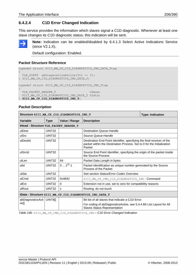
The Application Interface 206/390
sercos Master | Protocol API DOC081103API11EN | Revision 11 | English | 2013-09 | Released | Public © Hilscher, 2008-2013
6.4.2.4 C1D Error Changed Indication
This service provides the information which slaves signal a C1D diagnostic. Whenever at least one slave changes its C1D diagnostic status, this indication will be sent.
Note: Indication can be enabled/disabled by 6.4.1.3 Select Active Indications Service (since V2.1.X).
Default configuration: Enabled.
Packet Structure Reference
typedef struct SIII_MA_CP_C1D_DIAGNOSTICS_IND_DATA_Ttag { TLR_UINT8 abDiagnosticsActive[512 >> 3];
} SIII_MA_CP_C1D_DIAGNOSTICS_IND_DATA_T; typedef struct SIII_MA_CP_C1D_DIAGNOSTICS_IND_Ttag { TLR_PACKET_HEADER_T tHead; SIII_MA_CP_C1D_DIAGNOSTICS_IND_DATA_T tData;
} SIII_MA_CP_C1D_DIAGNOSTICS_IND_T;
Packet Description
Structure SIII_MA_CP_C1D_DIAGNOSTICS_IND_T Type: Indication
Variable Type Value / Range Description
tHead - Structure TLR_PACKET_HEADER_T
ulDest UINT32 Destination Queue-Handle
ulSrc UINT32 Source Queue-Handle
ulDestId UINT32 Destination End Point Identifier, specifying the final receiver of the packet within the Destination Process. Set to 0 for the Initialization Packet
ulSrcId UINT32 Source End Point Identifier, specifying the origin of the packet inside the Source Process
ulLen UINT32 64 Packet Data Length in bytes
ulId UINT32 0 ... 232-1 Packet Identification as unique number generated by the Source Process of the Packet
ulSta UINT32 See section Status/Error Codes Overview
ulCmd UINT32 0x4842 SIII_MA_CP_CMD_C1D_DIAGNOSTICS_IND - Command
ulExt UINT32 0 Extension not in use, set to zero for compatibility reasons
ulRout UINT32 x Routing, do not touch
tData - Structure SIII_MA_CP_C1D_DIAGNOSTICS_IND_DATA_T
abDiagnosticsActive[]
UINT8[] Bit list of all slaves that indicate a C1D Error.
For coding of abDiagnosticsActive, see 5.4.4 Bit List Layout for All Slaves Status Representation
Table 146: SIII_MA_CP_CMD_C1D_DIAGNOSTICS_IND – C1D Error Changed Indication

The Application Interface 207/390
sercos Master | Protocol API DOC081103API11EN | Revision 11 | English | 2013-09 | Released | Public © Hilscher, 2008-2013
Packet Structure Reference
typedef struct SIII_MA_CP_C1D_DIAGNOSTICS_RES_Ttag { TLR_PACKET_HEADER_T tHead;
} SIII_MA_CP_C1D_DIAGNOSTICS_RES_T;
Packet Description
Structure SIII_MA_CP_C1D_DIAGNOSTICS_RES_T Type: Response
Variable Type Value / Range Description
Head - Structure TLR_PACKET_HEADER_T
ulDest UINT32 Destination queue handle, unchanged
ulSrc UINT32 Source queue handle, unchanged
ulDestId UINT32 Destination End Point Identifier, specifying the final receiver of the packet within the Destination Process. Set to 0 for the Initialization Packet
ulSrcId UINT32 Source End Point Identifier, specifying the origin of the packet inside the Source Process
ulLen UINT32 0 Packet Data Length in bytes
ulId UINT32 0 ... 232-1 Packet Identification, unchanged
ulSta UINT32 See section Status/Error Codes Overview
ulCmd UINT32 0x4843 SIII_MA_CP_CMD_C1D_DIAGNOSTICS_RES – Command
ulExt UINT32 0 Extension, reserved
ulRout UINT32 x Routing information, do not change
Table 147: SIII_MA_CP_CMD_C1D_DIAGNOSTICS_RES – C1D Error Changed Response
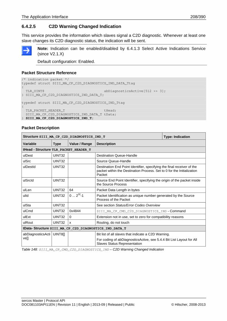
The Application Interface 208/390
sercos Master | Protocol API DOC081103API11EN | Revision 11 | English | 2013-09 | Released | Public © Hilscher, 2008-2013
6.4.2.5 C2D Warning Changed Indication
This service provides the information which slaves signal a C2D diagnostic. Whenever at least one slave changes its C2D diagnostic status, the indication will be sent.
Note: Indication can be enabled/disabled by 6.4.1.3 Select Active Indications Service (since V2.1.X)
Default configuration: Enabled.
Packet Structure Reference
/* indication packet */ typedef struct SIII_MA_CP_C2D_DIAGNOSTICS_IND_DATA_Ttag { TLR_UINT8 abDiagnosticsActive[512 >> 3]; } SIII_MA_CP_C2D_DIAGNOSTICS_IND_DATA_T; typedef struct SIII_MA_CP_C2D_DIAGNOSTICS_IND_Ttag { TLR_PACKET_HEADER_T tHead; SIII_MA_CP_C2D_DIAGNOSTICS_IND_DATA_T tData; } SIII_MA_CP_C2D_DIAGNOSTICS_IND_T;
Packet Description
Structure SIII_MA_CP_C2D_DIAGNOSTICS_IND_T Type: Indication
Variable Type Value / Range Description
tHead - Structure TLR_PACKET_HEADER_T
ulDest UINT32 Destination Queue-Handle
ulSrc UINT32 Source Queue-Handle
ulDestId UINT32 Destination End Point Identifier, specifying the final receiver of the packet within the Destination Process. Set to 0 for the Initialization Packet
ulSrcId UINT32 Source End Point Identifier, specifying the origin of the packet inside the Source Process
ulLen UINT32 64 Packet Data Length in bytes
ulId UINT32 0 ... 232-1 Packet Identification as unique number generated by the Source Process of the Packet
ulSta UINT32 See section Status/Error Codes Overview
ulCmd UINT32 0x4844 SIII_MA_CP_CMD_C2D_DIAGNOSTICS_IND - Command
ulExt UINT32 0 Extension not in use, set to zero for compatibility reasons
ulRout UINT32 x Routing, do not touch
tData- Structure SIII_MA_CP_C2D_DIAGNOSTICS_IND_DATA_T
abDiagnosticsActive[]
UINT8[] Bit list of all slaves that indicate a C2D Warning.
For coding of abDiagnosticsActive, see 5.4.4 Bit List Layout for All Slaves Status Representation
Table 148: SIII_MA_CP_CMD_C2D_DIAGNOSTICS_IND – C2D Warning Changed Indication
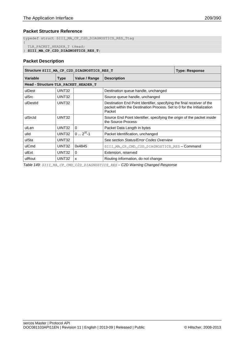
The Application Interface 209/390
sercos Master | Protocol API DOC081103API11EN | Revision 11 | English | 2013-09 | Released | Public © Hilscher, 2008-2013
Packet Structure Reference
typedef struct SIII_MA_CP_C2D_DIAGNOSTICS_RES_Ttag { TLR_PACKET_HEADER_T tHead;
} SIII_MA_CP_C2D_DIAGNOSTICS_RES_T;
Packet Description
Structure SIII_MA_CP_C2D_DIAGNOSTICS_RES_T Type: Response
Variable Type Value / Range Description
Head - Structure TLR_PACKET_HEADER_T
ulDest UINT32 Destination queue handle, unchanged
ulSrc UINT32 Source queue handle, unchanged
ulDestId UINT32 Destination End Point Identifier, specifying the final receiver of the packet within the Destination Process. Set to 0 for the Initialization Packet
ulSrcId UINT32 Source End Point Identifier, specifying the origin of the packet inside the Source Process
ulLen UINT32 0 Packet Data Length in bytes
ulId UINT32 0 ... 232-1 Packet Identification, unchanged
ulSta UINT32 See section Status/Error Codes Overview
ulCmd UINT32 0x4845 SIII_MA_CP_CMD_C2D_DIAGNOSTICS_RES – Command
ulExt UINT32 0 Extension, reserved
ulRout UINT32 x Routing information, do not change
Table 149: SIII_MA_CP_CMD_C2D_DIAGNOSTICS_RES – C2D Warning Changed Response
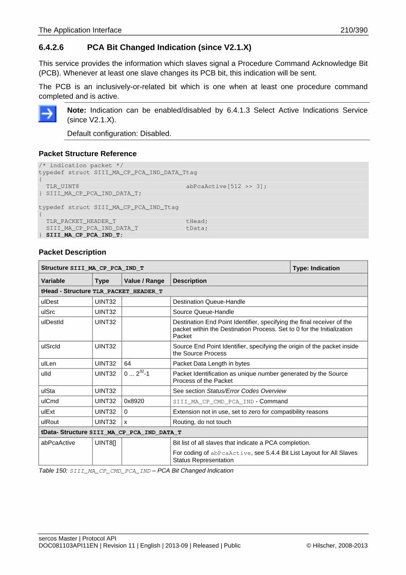
The Application Interface 210/390
sercos Master | Protocol API DOC081103API11EN | Revision 11 | English | 2013-09 | Released | Public © Hilscher, 2008-2013
6.4.2.6 PCA Bit Changed Indication (since V2.1.X)
This service provides the information which slaves signal a Procedure Command Acknowledge Bit (PCB). Whenever at least one slave changes its PCB bit, this indication will be sent.
The PCB is an inclusively-or-related bit which is one when at least one procedure command completed and is active.
Note: Indication can be enabled/disabled by 6.4.1.3 Select Active Indications Service (since V2.1.X).
Default configuration: Disabled.
Packet Structure Reference
/* indication packet */ typedef struct SIII_MA_CP_PCA_IND_DATA_Ttag { TLR_UINT8 abPcaActive[512 >> 3]; } SIII_MA_CP_PCA_IND_DATA_T; typedef struct SIII_MA_CP_PCA_IND_Ttag { TLR_PACKET_HEADER_T tHead; SIII_MA_CP_PCA_IND_DATA_T tData; } SIII_MA_CP_PCA_IND_T;
Packet Description
Structure SIII_MA_CP_PCA_IND_T Type: Indication
Variable Type Value / Range Description
tHead - Structure TLR_PACKET_HEADER_T
ulDest UINT32 Destination Queue-Handle
ulSrc UINT32 Source Queue-Handle
ulDestId UINT32 Destination End Point Identifier, specifying the final receiver of the packet within the Destination Process. Set to 0 for the Initialization Packet
ulSrcId UINT32 Source End Point Identifier, specifying the origin of the packet inside the Source Process
ulLen UINT32 64 Packet Data Length in bytes
ulId UINT32 0 ... 232-1 Packet Identification as unique number generated by the Source Process of the Packet
ulSta UINT32 See section Status/Error Codes Overview
ulCmd UINT32 0x8920 SIII_MA_CP_CMD_PCA_IND - Command
ulExt UINT32 0 Extension not in use, set to zero for compatibility reasons
ulRout UINT32 x Routing, do not touch
tData- Structure SIII_MA_CP_PCA_IND_DATA_T
abPcaActive UINT8[] Bit list of all slaves that indicate a PCA completion.
For coding of abPcaActive, see 5.4.4 Bit List Layout for All Slaves Status Representation
Table 150: SIII_MA_CP_CMD_PCA_IND – PCA Bit Changed Indication
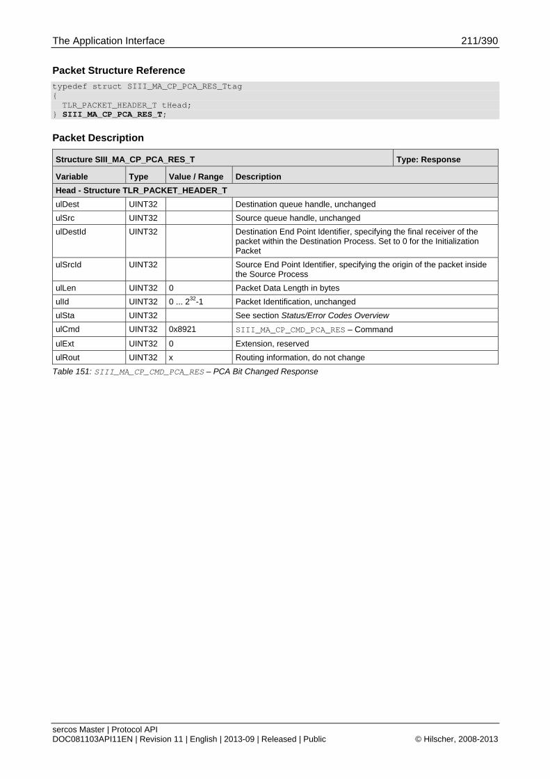
The Application Interface 211/390
sercos Master | Protocol API DOC081103API11EN | Revision 11 | English | 2013-09 | Released | Public © Hilscher, 2008-2013
Packet Structure Reference
typedef struct SIII_MA_CP_PCA_RES_Ttag { TLR_PACKET_HEADER_T tHead;
} SIII_MA_CP_PCA_RES_T;
Packet Description
Structure SIII_MA_CP_PCA_RES_T Type: Response
Variable Type Value / Range Description
Head - Structure TLR_PACKET_HEADER_T
ulDest UINT32 Destination queue handle, unchanged
ulSrc UINT32 Source queue handle, unchanged
ulDestId UINT32 Destination End Point Identifier, specifying the final receiver of the packet within the Destination Process. Set to 0 for the Initialization Packet
ulSrcId UINT32 Source End Point Identifier, specifying the origin of the packet inside the Source Process
ulLen UINT32 0 Packet Data Length in bytes
ulId UINT32 0 ... 232-1 Packet Identification, unchanged
ulSta UINT32 See section Status/Error Codes Overview
ulCmd UINT32 0x8921 SIII_MA_CP_CMD_PCA_RES – Command
ulExt UINT32 0 Extension, reserved
ulRout UINT32 x Routing information, do not change
Table 151: SIII_MA_CP_CMD_PCA_RES – PCA Bit Changed Response
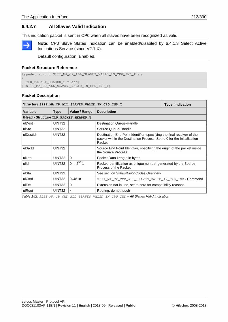
The Application Interface 212/390
sercos Master | Protocol API DOC081103API11EN | Revision 11 | English | 2013-09 | Released | Public © Hilscher, 2008-2013
6.4.2.7 All Slaves Valid Indication
This indication packet is sent in CP0 when all slaves have been recognized as valid.
Note: CP0 Slave States Indication can be enabled/disabled by 6.4.1.3 Select Active Indications Service (since V2.1.X).
Default configuration: Enabled.
Packet Structure Reference
typedef struct SIII_MA_CP_ALL_SLAVES_VALID_IN_CP0_IND_Ttag { TLR_PACKET_HEADER_T tHead; } SIII_MA_CP_ALL_SLAVES_VALID_IN_CP0_IND_T;
Packet Description
Structure SIII_MA_CP_ALL_SLAVES_VALID_IN_CP0_IND_T Type: Indication
Variable Type Value / Range Description
tHead - Structure TLR_PACKET_HEADER_T
ulDest UINT32 Destination Queue-Handle
ulSrc UINT32 Source Queue-Handle
ulDestId UINT32 Destination End Point Identifier, specifying the final receiver of the packet within the Destination Process. Set to 0 for the Initialization Packet
ulSrcId UINT32 Source End Point Identifier, specifying the origin of the packet inside the Source Process
ulLen UINT32 0 Packet Data Length in bytes
ulId UINT32 0 ... 232-1 Packet Identification as unique number generated by the Source Process of the Packet
ulSta UINT32 See section Status/Error Codes Overview
ulCmd UINT32 0x4818 SIII_MA_CP_CMD_ALL_SLAVES_VALID_IN_CP0_IND - Command
ulExt UINT32 0 Extension not in use, set to zero for compatibility reasons
ulRout UINT32 x Routing, do not touch
Table 152: SIII_MA_CP_CMD_ALL_SLAVES_VALID_IN_CP0_IND – All Slaves Valid Indication

The Application Interface 213/390
sercos Master | Protocol API DOC081103API11EN | Revision 11 | English | 2013-09 | Released | Public © Hilscher, 2008-2013
Packet Structure Reference
typedef struct SIII_MA_CP_ALL_SLAVES_VALID_IN_CP0_RES_Ttag { TLR_PACKET_HEADER_T tHead; } SIII_MA_CP_ALL_SLAVES_VALID_IN_CP0_RES_T;
Packet Description
Structure SIII_MA_CP_ALL_SLAVES_VALID_IN_CP0_RES_T Type: Response
Variable Type Value / Range Description
tHead - Structure TLR_PACKET_HEADER_T
ulDest UINT32 Destination Queue-Handle
ulSrc UINT32 Source Queue-Handle
ulDestId UINT32 Destination End Point Identifier, specifying the final receiver of the packet within the Destination Process. Set to 0 for the Initialization Packet
ulSrcId UINT32 Source End Point Identifier, specifying the origin of the packet inside the Source Process
ulLen UINT32 0 Packet Data Length in bytes
ulId UINT32 0 ... 232-1 Packet Identification as unique number generated by the Source Process of the Packet
ulSta UINT32 See section Status/Error Codes Overview
ulCmd UINT32 0x4819 SIII_MA_CP_CMD_ALL_SLAVES_VALID_IN_CP0_RES - Command
ulExt UINT32 0 Extension not in use, set to zero for compatibility reasons
ulRout UINT32 x Routing, do not touch
Table 153: SIII_MA_CP_CMD_ALL_SLAVES_VALID_IN_CP0_RES – All Slaves Valid Response
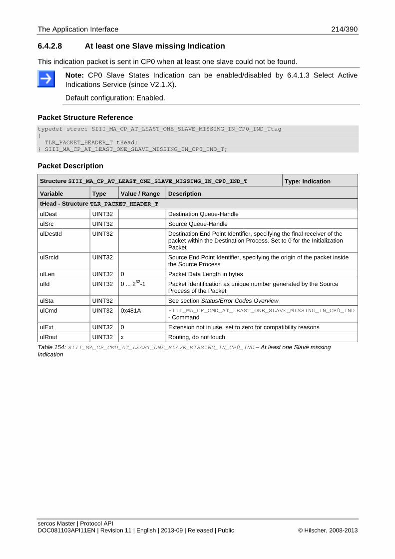
The Application Interface 214/390
sercos Master | Protocol API DOC081103API11EN | Revision 11 | English | 2013-09 | Released | Public © Hilscher, 2008-2013
6.4.2.8 At least one Slave missing Indication
This indication packet is sent in CP0 when at least one slave could not be found.
Note: CP0 Slave States Indication can be enabled/disabled by 6.4.1.3 Select Active Indications Service (since V2.1.X).
Default configuration: Enabled.
Packet Structure Reference
typedef struct SIII_MA_CP_AT_LEAST_ONE_SLAVE_MISSING_IN_CP0_IND_Ttag { TLR_PACKET_HEADER_T tHead; } SIII_MA_CP_AT_LEAST_ONE_SLAVE_MISSING_IN_CP0_IND_T;
Packet Description
Structure SIII_MA_CP_AT_LEAST_ONE_SLAVE_MISSING_IN_CP0_IND_T Type: Indication
Variable Type Value / Range Description
tHead - Structure TLR_PACKET_HEADER_T
ulDest UINT32 Destination Queue-Handle
ulSrc UINT32 Source Queue-Handle
ulDestId UINT32 Destination End Point Identifier, specifying the final receiver of the packet within the Destination Process. Set to 0 for the Initialization Packet
ulSrcId UINT32 Source End Point Identifier, specifying the origin of the packet inside the Source Process
ulLen UINT32 0 Packet Data Length in bytes
ulId UINT32 0 ... 232-1 Packet Identification as unique number generated by the Source Process of the Packet
ulSta UINT32 See section Status/Error Codes Overview
ulCmd UINT32 0x481A SIII_MA_CP_CMD_AT_LEAST_ONE_SLAVE_MISSING_IN_CP0_IND - Command
ulExt UINT32 0 Extension not in use, set to zero for compatibility reasons
ulRout UINT32 x Routing, do not touch
Table 154: SIII_MA_CP_CMD_AT_LEAST_ONE_SLAVE_MISSING_IN_CP0_IND – At least one Slave missing Indication
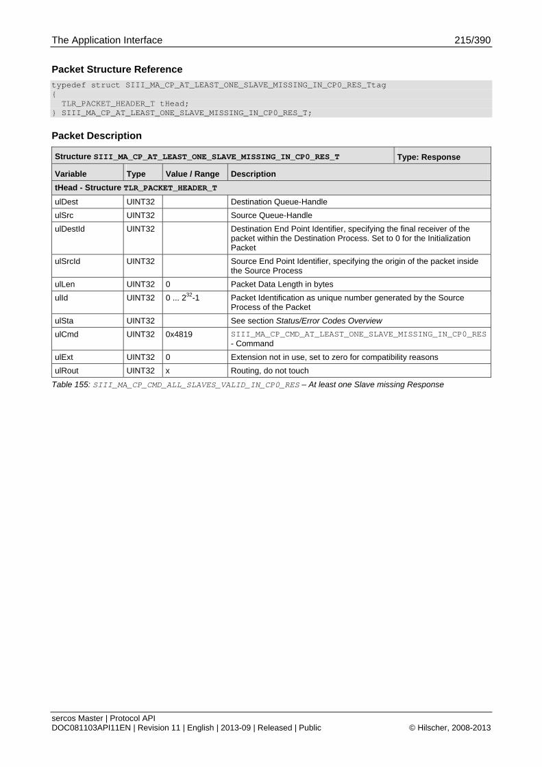
The Application Interface 215/390
sercos Master | Protocol API DOC081103API11EN | Revision 11 | English | 2013-09 | Released | Public © Hilscher, 2008-2013
Packet Structure Reference
typedef struct SIII_MA_CP_AT_LEAST_ONE_SLAVE_MISSING_IN_CP0_RES_Ttag { TLR_PACKET_HEADER_T tHead; } SIII_MA_CP_AT_LEAST_ONE_SLAVE_MISSING_IN_CP0_RES_T;
Packet Description
Structure SIII_MA_CP_AT_LEAST_ONE_SLAVE_MISSING_IN_CP0_RES_T Type: Response
Variable Type Value / Range Description
tHead - Structure TLR_PACKET_HEADER_T
ulDest UINT32 Destination Queue-Handle
ulSrc UINT32 Source Queue-Handle
ulDestId UINT32 Destination End Point Identifier, specifying the final receiver of the packet within the Destination Process. Set to 0 for the Initialization Packet
ulSrcId UINT32 Source End Point Identifier, specifying the origin of the packet inside the Source Process
ulLen UINT32 0 Packet Data Length in bytes
ulId UINT32 0 ... 232-1 Packet Identification as unique number generated by the Source Process of the Packet
ulSta UINT32 See section Status/Error Codes Overview
ulCmd UINT32 0x4819 SIII_MA_CP_CMD_AT_LEAST_ONE_SLAVE_MISSING_IN_CP0_RES - Command
ulExt UINT32 0 Extension not in use, set to zero for compatibility reasons
ulRout UINT32 x Routing, do not touch
Table 155: SIII_MA_CP_CMD_ALL_SLAVES_VALID_IN_CP0_RES – At least one Slave missing Response

The Application Interface 216/390
sercos Master | Protocol API DOC081103API11EN | Revision 11 | English | 2013-09 | Released | Public © Hilscher, 2008-2013
6.4.2.9 All Slaves in Two Lines Indication
This indication packet is sent in CP0 when all slaves are found and placed in two lines.
Note: CP0 Slave States Indication can be enabled/disabled by 6.4.1.3 Select Active Indications Service (since V2.1.X).
Default configuration: Enabled.
Packet Structure Reference
typedef struct SIII_MA_CP_ALL_SLAVES_IN_TWO_LINES_IND_Ttag { TLR_PACKET_HEADER_T tHead; } SIII_MA_CP_ALL_SLAVES_IN_TWO_LINES_IND_T;
Packet Description
Structure SIII_MA_CP_ALL_SLAVES_IN_TWO_LINES_IND_T Type: Indication
Variable Type Value / Range Description
tHead - Structure TLR_PACKET_HEADER_T
ulDest UINT32 Destination Queue-Handle
ulSrc UINT32 Source Queue-Handle
ulDestId UINT32 Destination End Point Identifier, specifying the final receiver of the packet within the Destination Process. Set to 0 for the Initialization Packet
ulSrcId UINT32 Source End Point Identifier, specifying the origin of the packet inside the Source Process
ulLen UINT32 0 Packet Data Length in bytes
ulId UINT32 0 ... 232-1 Packet Identification as unique number generated by the Source Process of the Packet
ulSta UINT32 See section Status/Error Codes Overview
ulCmd UINT32 0x481C SIII_MA_CP_CMD_ALL_SLAVES_IN_TWO_LINES_IND - Command
ulExt UINT32 0 Extension not in use, set to zero for compatibility reasons
ulRout UINT32 x Routing, do not touch
Table 156: SIII_MA_CP_CMD_ALL_SLAVES_IN_TWO_LINES_IND – All Slaves in Two Lines Indication

The Application Interface 217/390
sercos Master | Protocol API DOC081103API11EN | Revision 11 | English | 2013-09 | Released | Public © Hilscher, 2008-2013
Packet Structure Reference
typedef struct SIII_MA_CP_ALL_SLAVES_IN_TWO_LINES_RES_Ttag { TLR_PACKET_HEADER_T tHead; } SIII_MA_CP_ALL_SLAVES_IN_TWO_LINES_RES_T;
Packet Description
Structure SIII_MA_CP_ALL_SLAVES_IN_TWO_LINES_RES_T Type: Response
Variable Type Value / Range Description
tHead - Structure TLR_PACKET_HEADER_T
ulDest UINT32 Destination Queue-Handle
ulSrc UINT32 Source Queue-Handle
ulDestId UINT32 Destination End Point Identifier, specifying the final receiver of the packet within the Destination Process. Set to 0 for the Initialization Packet
ulSrcId UINT32 Source End Point Identifier, specifying the origin of the packet inside the Source Process
ulLen UINT32 0 Packet Data Length in bytes
ulId UINT32 0 ... 232-1 Packet Identification as unique number generated by the Source Process of the Packet
ulSta UINT32 See section Status/Error Codes Overview
ulCmd UINT32 0x481D SIII_MA_CP_CMD_ALL_SLAVES_IN_TWO_LINES_RES - Command
ulExt UINT32 0 Extension not in use, set to zero for compatibility reasons
ulRout UINT32 x Routing, do not touch
Table 157: SIII_MA_CP_CMD_ALL_SLAVES_IN_TWO_LINES_RES – All slaves in Two Lines Response
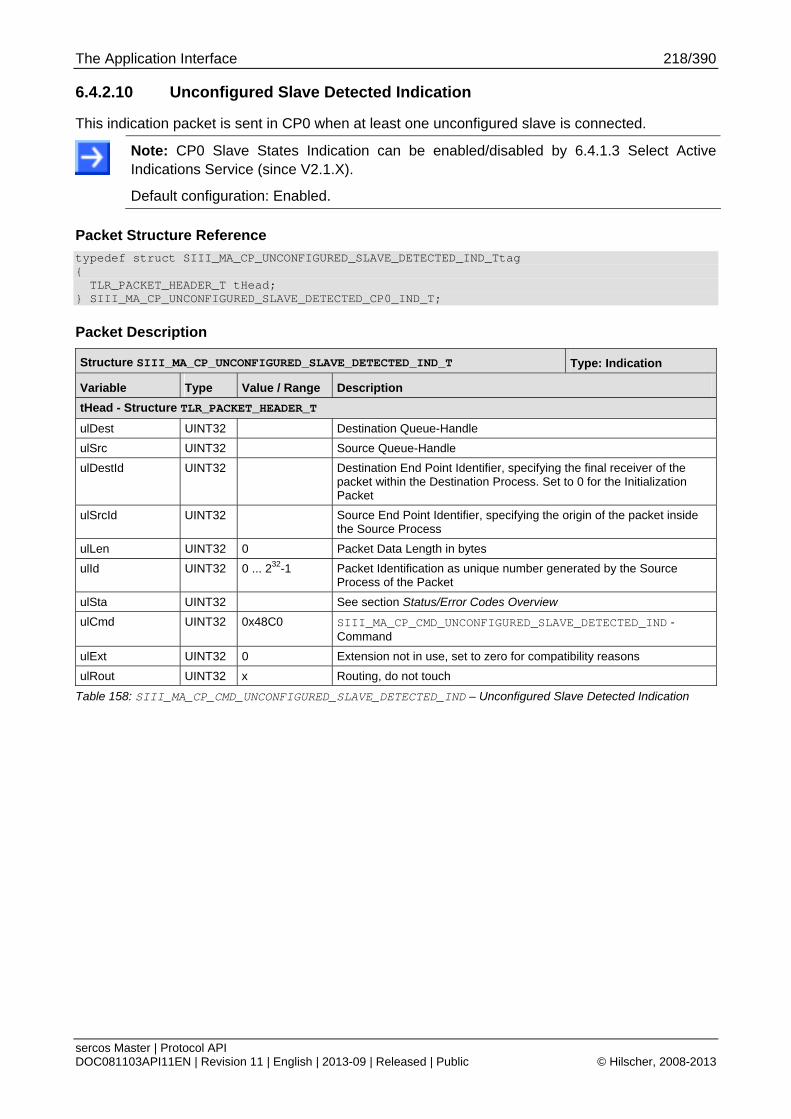
The Application Interface 218/390
sercos Master | Protocol API DOC081103API11EN | Revision 11 | English | 2013-09 | Released | Public © Hilscher, 2008-2013
6.4.2.10 Unconfigured Slave Detected Indication
This indication packet is sent in CP0 when at least one unconfigured slave is connected.
Note: CP0 Slave States Indication can be enabled/disabled by 6.4.1.3 Select Active Indications Service (since V2.1.X).
Default configuration: Enabled.
Packet Structure Reference
typedef struct SIII_MA_CP_UNCONFIGURED_SLAVE_DETECTED_IND_Ttag { TLR_PACKET_HEADER_T tHead; } SIII_MA_CP_UNCONFIGURED_SLAVE_DETECTED_CP0_IND_T;
Packet Description
Structure SIII_MA_CP_UNCONFIGURED_SLAVE_DETECTED_IND_T Type: Indication
Variable Type Value / Range Description
tHead - Structure TLR_PACKET_HEADER_T
ulDest UINT32 Destination Queue-Handle
ulSrc UINT32 Source Queue-Handle
ulDestId UINT32 Destination End Point Identifier, specifying the final receiver of the packet within the Destination Process. Set to 0 for the Initialization Packet
ulSrcId UINT32 Source End Point Identifier, specifying the origin of the packet inside the Source Process
ulLen UINT32 0 Packet Data Length in bytes
ulId UINT32 0 ... 232-1 Packet Identification as unique number generated by the Source Process of the Packet
ulSta UINT32 See section Status/Error Codes Overview
ulCmd UINT32 0x48C0 SIII_MA_CP_CMD_UNCONFIGURED_SLAVE_DETECTED_IND - Command
ulExt UINT32 0 Extension not in use, set to zero for compatibility reasons
ulRout UINT32 x Routing, do not touch
Table 158: SIII_MA_CP_CMD_UNCONFIGURED_SLAVE_DETECTED_IND – Unconfigured Slave Detected Indication
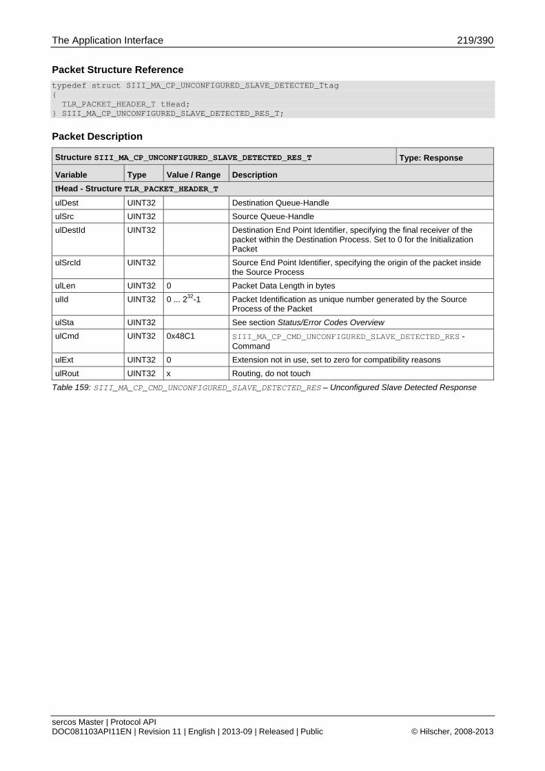
The Application Interface 219/390
sercos Master | Protocol API DOC081103API11EN | Revision 11 | English | 2013-09 | Released | Public © Hilscher, 2008-2013
Packet Structure Reference
typedef struct SIII_MA_CP_UNCONFIGURED_SLAVE_DETECTED_Ttag { TLR_PACKET_HEADER_T tHead; } SIII_MA_CP_UNCONFIGURED_SLAVE_DETECTED_RES_T;
Packet Description
Structure SIII_MA_CP_UNCONFIGURED_SLAVE_DETECTED_RES_T Type: Response
Variable Type Value / Range Description
tHead - Structure TLR_PACKET_HEADER_T
ulDest UINT32 Destination Queue-Handle
ulSrc UINT32 Source Queue-Handle
ulDestId UINT32 Destination End Point Identifier, specifying the final receiver of the packet within the Destination Process. Set to 0 for the Initialization Packet
ulSrcId UINT32 Source End Point Identifier, specifying the origin of the packet inside the Source Process
ulLen UINT32 0 Packet Data Length in bytes
ulId UINT32 0 ... 232-1 Packet Identification as unique number generated by the Source Process of the Packet
ulSta UINT32 See section Status/Error Codes Overview
ulCmd UINT32 0x48C1 SIII_MA_CP_CMD_UNCONFIGURED_SLAVE_DETECTED_RES - Command
ulExt UINT32 0 Extension not in use, set to zero for compatibility reasons
ulRout UINT32 x Routing, do not touch
Table 159: SIII_MA_CP_CMD_UNCONFIGURED_SLAVE_DETECTED_RES – Unconfigured Slave Detected Response
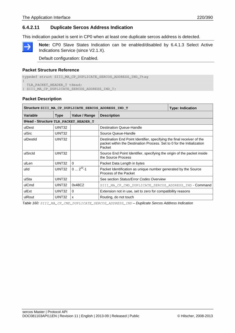
The Application Interface 220/390
sercos Master | Protocol API DOC081103API11EN | Revision 11 | English | 2013-09 | Released | Public © Hilscher, 2008-2013
6.4.2.11 Duplicate Sercos Address Indication
This indication packet is sent in CP0 when at least one duplicate sercos address is detected.
Note: CP0 Slave States Indication can be enabled/disabled by 6.4.1.3 Select Active Indications Service (since V2.1.X).
Default configuration: Enabled.
Packet Structure Reference
typedef struct SIII_MA_CP_DUPLICATE_SERCOS_ADDRESS_IND_Ttag { TLR_PACKET_HEADER_T tHead; } SIII_MA_CP_DUPLICATE_SERCOS_ADDRESS_IND_T;
Packet Description
Structure SIII_MA_CP_DUPLICATE_SERCOS_ADDRESS_IND_T Type: Indication
Variable Type Value / Range Description
tHead - Structure TLR_PACKET_HEADER_T
ulDest UINT32 Destination Queue-Handle
ulSrc UINT32 Source Queue-Handle
ulDestId UINT32 Destination End Point Identifier, specifying the final receiver of the packet within the Destination Process. Set to 0 for the Initialization Packet
ulSrcId UINT32 Source End Point Identifier, specifying the origin of the packet inside the Source Process
ulLen UINT32 0 Packet Data Length in bytes
ulId UINT32 0 ... 232-1 Packet Identification as unique number generated by the Source Process of the Packet
ulSta UINT32 See section Status/Error Codes Overview
ulCmd UINT32 0x48C2 SIII_MA_CP_CMD_DUPLICATE_SERCOS_ADDRESS_IND - Command
ulExt UINT32 0 Extension not in use, set to zero for compatibility reasons
ulRout UINT32 x Routing, do not touch
Table 160: SIII_MA_CP_CMD_DUPLICATE_SERCOS_ADDRESS_IND – Duplicate Sercos Address Indication

The Application Interface 221/390
sercos Master | Protocol API DOC081103API11EN | Revision 11 | English | 2013-09 | Released | Public © Hilscher, 2008-2013
Packet Structure Reference
typedef struct SIII_MA_CP_DUPLICATE_SERCOS_ADDRESS_RES_Ttag { TLR_PACKET_HEADER_T tHead; } SIII_MA_CP_DUPLICATE_SERCOS_ADDRESS_RES_T;
Packet Description
Structure SIII_MA_CP_DUPLICATE_SERCOS_ADDRESS_RES_T Type: Response
Variable Type Value / Range Description
tHead - Structure TLR_PACKET_HEADER_T
ulDest UINT32 Destination Queue-Handle
ulSrc UINT32 Source Queue-Handle
ulDestId UINT32 Destination End Point Identifier, specifying the final receiver of the packet within the Destination Process. Set to 0 for the Initialization Packet
ulSrcId UINT32 Source End Point Identifier, specifying the origin of the packet inside the Source Process
ulLen UINT32 0 Packet Data Length in bytes
ulId UINT32 0 ... 232-1 Packet Identification as unique number generated by the Source Process of the Packet
ulSta UINT32 See section Status/Error Codes Overview
ulCmd UINT32 0x48C3 SIII_MA_CP_CMD_DUPLICATE_SERCOS_ADDRESS_RES - Command
ulExt UINT32 0 Extension not in use, set to zero for compatibility reasons
ulRout UINT32 x Routing, do not touch
Table 161: SIII_MA_CP_CMD_DUPLICATE_SERCOS_ADDRESS_RES – Duplicate Sercos Address Response

The Application Interface 222/390
sercos Master | Protocol API DOC081103API11EN | Revision 11 | English | 2013-09 | Released | Public © Hilscher, 2008-2013
6.4.2.12 Invalid Sercos Address Detected Indication
This indication packet is sent in CP0 when at least one invalid sercos address has been detected.
Note: CP0 Slave States Indication can be enabled/disabled by 6.4.1.3 Select Active Indications Service (since V2.1.X).
Default configuration: Enabled.
Packet Structure Reference
typedef struct SIII_MA_CP_INVALID_SERCOS_ADDRESS_DETECTED_IND_Ttag { TLR_PACKET_HEADER_T tHead; } SIII_MA_CP_INVALID_SERCOS_ADDRESS_DETECTED_IND_T;
Packet Description
Structure SIII_MA_CP_INVALID_SERCOS_ADDRESS_DETECTED_IND_T Type: Indication
Variable Type Value / Range Description
tHead - Structure TLR_PACKET_HEADER_T
ulDest UINT32 Destination Queue-Handle
ulSrc UINT32 Source Queue-Handle
ulDestId UINT32 Destination End Point Identifier, specifying the final receiver of the packet within the Destination Process. Set to 0 for the Initialization Packet
ulSrcId UINT32 Source End Point Identifier, specifying the origin of the packet inside the Source Process
ulLen UINT32 0 Packet Data Length in bytes
ulId UINT32 0 ... 232-1 Packet Identification as unique number generated by the Source Process of the Packet
ulSta UINT32 See section Status/Error Codes Overview
ulCmd UINT32 0x486A SIII_MA_CP_CMD_INVALID_SERCOS_ADDRESS_DETECTED_IND - Command
ulExt UINT32 0 Extension not in use, set to zero for compatibility reasons
ulRout UINT32 x Routing, do not touch
Table 162: SIII_MA_CP_CMD_INVALID_SERCOS_ADDRESS_DETECTED_IND – Invalid Sercos Address Detected Indication

The Application Interface 223/390
sercos Master | Protocol API DOC081103API11EN | Revision 11 | English | 2013-09 | Released | Public © Hilscher, 2008-2013
Packet Structure Reference
typedef struct SIII_MA_CP_ALL_SLAVES_VALID_IN_CP0_RES_Ttag { TLR_PACKET_HEADER_T tHead; } SIII_MA_CP_ALL_SLAVES_VALID_IN_CP0_RES_T;
Packet Description
Structure SIII_MA_CP_ALL_SLAVES_VALID_IN_CP0_RES_T Type: Response
Variable Type Value / Range Description
tHead - Structure TLR_PACKET_HEADER_T
ulDest UINT32 Destination Queue-Handle
ulSrc UINT32 Source Queue-Handle
ulDestId UINT32 Destination End Point Identifier, specifying the final receiver of the packet within the Destination Process. Set to 0 for the Initialization Packet
ulSrcId UINT32 Source End Point Identifier, specifying the origin of the packet inside the Source Process
ulLen UINT32 0 Packet Data Length in bytes
ulId UINT32 0 ... 232-1 Packet Identification as unique number generated by the Source Process of the Packet
ulSta UINT32 See section Status/Error Codes Overview
ulCmd UINT32 0x486B SIII_MA_CP_CMD_INVALID_SERCOS_ADDRESS_DETECTED_RES - Command
ulExt UINT32 0 Extension not in use, set to zero for compatibility reasons
ulRout UINT32 x Routing, do not touch
Table 163: SIII_MA_CP_CMD_INVALID_SERCOS_ADDRESS_DETECTED_RES – Invalid Sercos Address Detected Response
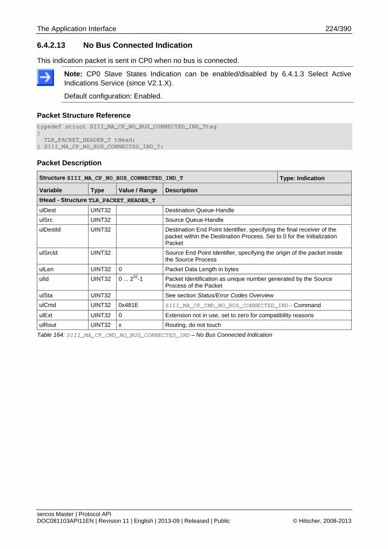
The Application Interface 224/390
sercos Master | Protocol API DOC081103API11EN | Revision 11 | English | 2013-09 | Released | Public © Hilscher, 2008-2013
6.4.2.13 No Bus Connected Indication
This indication packet is sent in CP0 when no bus is connected.
Note: CP0 Slave States Indication can be enabled/disabled by 6.4.1.3 Select Active Indications Service (since V2.1.X).
Default configuration: Enabled.
Packet Structure Reference
typedef struct SIII_MA_CP_NO_BUS_CONNECTED_IND_Ttag { TLR_PACKET_HEADER_T tHead; } SIII_MA_CP_NO_BUS_CONNECTED_IND_T;
Packet Description
Structure SIII_MA_CP_NO_BUS_CONNECTED_IND_T Type: Indication
Variable Type Value / Range Description
tHead - Structure TLR_PACKET_HEADER_T
ulDest UINT32 Destination Queue-Handle
ulSrc UINT32 Source Queue-Handle
ulDestId UINT32 Destination End Point Identifier, specifying the final receiver of the packet within the Destination Process. Set to 0 for the Initialization Packet
ulSrcId UINT32 Source End Point Identifier, specifying the origin of the packet inside the Source Process
ulLen UINT32 0 Packet Data Length in bytes
ulId UINT32 0 ... 232-1 Packet Identification as unique number generated by the Source Process of the Packet
ulSta UINT32 See section Status/Error Codes Overview
ulCmd UINT32 0x481E SIII_MA_CP_CMD_NO_BUS_CONNECTED_IND - Command
ulExt UINT32 0 Extension not in use, set to zero for compatibility reasons
ulRout UINT32 x Routing, do not touch
Table 164: SIII_MA_CP_CMD_NO_BUS_CONNECTED_IND – No Bus Connected Indication

The Application Interface 225/390
sercos Master | Protocol API DOC081103API11EN | Revision 11 | English | 2013-09 | Released | Public © Hilscher, 2008-2013
Packet Structure Reference
typedef struct SIII_MA_CP_NO_BUS_CONNECTED_RES_Ttag { TLR_PACKET_HEADER_T tHead; } SIII_MA_CP_NO_BUS_CONNECTED_RES_T;
Packet Description
Structure SIII_MA_CP_NO_BUS_CONNECTED_RES_T Type: Response
Variable Type Value / Range Description
tHead - Structure TLR_PACKET_HEADER_T
ulDest UINT32 Destination Queue-Handle
ulSrc UINT32 Source Queue-Handle
ulDestId UINT32 Destination End Point Identifier, specifying the final receiver of the packet within the Destination Process. Set to 0 for the Initialization Packet
ulSrcId UINT32 Source End Point Identifier, specifying the origin of the packet inside the Source Process
ulLen UINT32 0 Packet Data Length in bytes
ulId UINT32 0 ... 232-1 Packet Identification as unique number generated by the Source Process of the Packet
ulSta UINT32 See section Status/Error Codes Overview
ulCmd UINT32 0x481F SIII_MA_CP_CMD_NO_BUS_CONNECTED_RES - Command
ulExt UINT32 0 Extension not in use, set to zero for compatibility reasons
ulRout UINT32 x Routing, do not touch
Table 165: SIII_MA_CP_CMD_NO_BUS_CONNECTED_RES – No Bus Connected Response
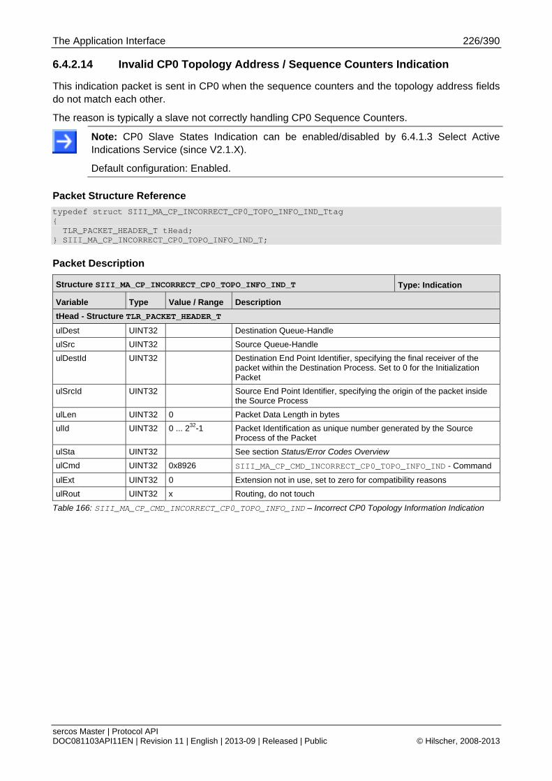
The Application Interface 226/390
sercos Master | Protocol API DOC081103API11EN | Revision 11 | English | 2013-09 | Released | Public © Hilscher, 2008-2013
6.4.2.14 Invalid CP0 Topology Address / Sequence Counters Indication
This indication packet is sent in CP0 when the sequence counters and the topology address fields do not match each other.
The reason is typically a slave not correctly handling CP0 Sequence Counters.
Note: CP0 Slave States Indication can be enabled/disabled by 6.4.1.3 Select Active Indications Service (since V2.1.X).
Default configuration: Enabled.
Packet Structure Reference
typedef struct SIII_MA_CP_INCORRECT_CP0_TOPO_INFO_IND_Ttag { TLR_PACKET_HEADER_T tHead; } SIII_MA_CP_INCORRECT_CP0_TOPO_INFO_IND_T;
Packet Description
Structure SIII_MA_CP_INCORRECT_CP0_TOPO_INFO_IND_T Type: Indication
Variable Type Value / Range Description
tHead - Structure TLR_PACKET_HEADER_T
ulDest UINT32 Destination Queue-Handle
ulSrc UINT32 Source Queue-Handle
ulDestId UINT32 Destination End Point Identifier, specifying the final receiver of the packet within the Destination Process. Set to 0 for the Initialization Packet
ulSrcId UINT32 Source End Point Identifier, specifying the origin of the packet inside the Source Process
ulLen UINT32 0 Packet Data Length in bytes
ulId UINT32 0 ... 232-1 Packet Identification as unique number generated by the Source Process of the Packet
ulSta UINT32 See section Status/Error Codes Overview
ulCmd UINT32 0x8926 SIII_MA_CP_CMD_INCORRECT_CP0_TOPO_INFO_IND - Command
ulExt UINT32 0 Extension not in use, set to zero for compatibility reasons
ulRout UINT32 x Routing, do not touch
Table 166: SIII_MA_CP_CMD_INCORRECT_CP0_TOPO_INFO_IND – Incorrect CP0 Topology Information Indication

The Application Interface 227/390
sercos Master | Protocol API DOC081103API11EN | Revision 11 | English | 2013-09 | Released | Public © Hilscher, 2008-2013
Packet Structure Reference
typedef struct SIII_MA_CP_INCORRECT_CP0_TOPO_INFO_RES_Ttag { TLR_PACKET_HEADER_T tHead; } SIII_MA_CP_INCORRECT_CP0_TOPO_INFO_RES_T;
Packet Description
Structure SIII_MA_CP_INCORRECT_CP0_TOPO_INFO_RES_T Type: Response
Variable Type Value / Range Description
tHead - Structure TLR_PACKET_HEADER_T
ulDest UINT32 Destination Queue-Handle
ulSrc UINT32 Source Queue-Handle
ulDestId UINT32 Destination End Point Identifier, specifying the final receiver of the packet within the Destination Process. Set to 0 for the Initialization Packet
ulSrcId UINT32 Source End Point Identifier, specifying the origin of the packet inside the Source Process
ulLen UINT32 0 Packet Data Length in bytes
ulId UINT32 0 ... 232-1 Packet Identification as unique number generated by the Source Process of the Packet
ulSta UINT32 See section Status/Error Codes Overview
ulCmd UINT32 0x8927 SIII_MA_CP_CMD_INCORRECT_CP0_TOPO_INFO_RES - Command
ulExt UINT32 0 Extension not in use, set to zero for compatibility reasons
ulRout UINT32 x Routing, do not touch
Table 167: SIII_MA_CP_CMD_INCORRECT_CP0_TOPO_INFO_RES – Incorrect CP0 Topology Information Response
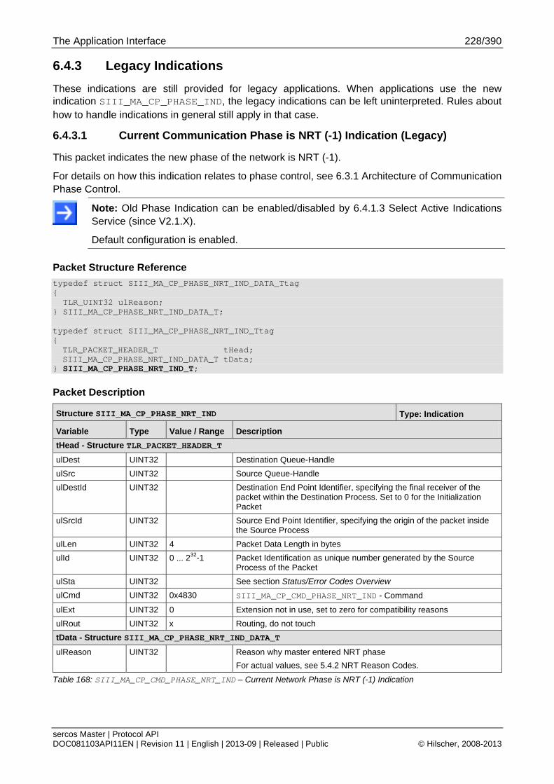
The Application Interface 228/390
sercos Master | Protocol API DOC081103API11EN | Revision 11 | English | 2013-09 | Released | Public © Hilscher, 2008-2013
6.4.3 Legacy Indications
These indications are still provided for legacy applications. When applications use the new indication SIII_MA_CP_PHASE_IND, the legacy indications can be left uninterpreted. Rules about how to handle indications in general still apply in that case.
6.4.3.1 Current Communication Phase is NRT (-1) Indication (Legacy)
This packet indicates the new phase of the network is NRT (-1).
For details on how this indication relates to phase control, see 6.3.1 Architecture of Communication Phase Control.
Note: Old Phase Indication can be enabled/disabled by 6.4.1.3 Select Active Indications Service (since V2.1.X).
Default configuration is enabled.
Packet Structure Reference
typedef struct SIII_MA_CP_PHASE_NRT_IND_DATA_Ttag { TLR_UINT32 ulReason; } SIII_MA_CP_PHASE_NRT_IND_DATA_T; typedef struct SIII_MA_CP_PHASE_NRT_IND_Ttag { TLR_PACKET_HEADER_T tHead; SIII_MA_CP_PHASE_NRT_IND_DATA_T tData;
} SIII_MA_CP_PHASE_NRT_IND_T;
Packet Description
Structure SIII_MA_CP_PHASE_NRT_IND Type: Indication
Variable Type Value / Range Description
tHead - Structure TLR_PACKET_HEADER_T
ulDest UINT32 Destination Queue-Handle
ulSrc UINT32 Source Queue-Handle
ulDestId UINT32 Destination End Point Identifier, specifying the final receiver of the packet within the Destination Process. Set to 0 for the Initialization Packet
ulSrcId UINT32 Source End Point Identifier, specifying the origin of the packet inside the Source Process
ulLen UINT32 4 Packet Data Length in bytes
ulId UINT32 0 ... 232-1 Packet Identification as unique number generated by the Source Process of the Packet
ulSta UINT32 See section Status/Error Codes Overview
ulCmd UINT32 0x4830 SIII_MA_CP_CMD_PHASE_NRT_IND - Command
ulExt UINT32 0 Extension not in use, set to zero for compatibility reasons
ulRout UINT32 x Routing, do not touch
tData - Structure SIII_MA_CP_PHASE_NRT_IND_DATA_T
ulReason UINT32 Reason why master entered NRT phase
For actual values, see 5.4.2 NRT Reason Codes.
Table 168: SIII_MA_CP_CMD_PHASE_NRT_IND – Current Network Phase is NRT (-1) Indication

The Application Interface 229/390
sercos Master | Protocol API DOC081103API11EN | Revision 11 | English | 2013-09 | Released | Public © Hilscher, 2008-2013
Packet Structure Reference
typedef struct SIII_MA_CP_PHASE_IND_NRT_RES_Ttag { TLR_PACKET_HEADER_T tHead;
} SIII_MA_CP_PHASE_IND_NRT_RES_T;
Packet Description
Structure SIII_MA_CP_PHASE_IND_NRT_RES_T Type: Response
Variable Type Value / Range Description
Head - Structure TLR_PACKET_HEADER_T
ulDest UINT32 Destination queue handle, unchanged
ulSrc UINT32 Source queue handle, unchanged
ulDestId UINT32 Destination End Point Identifier, specifying the final receiver of the packet within the Destination Process. Set to 0 for the Initialization Packet
ulSrcId UINT32 Source End Point Identifier, specifying the origin of the packet inside the Source Process
ulLen UINT32 0 Packet Data Length in bytes
ulId UINT32 0 ... 232-1 Packet Identification, unchanged
ulSta UINT32 See section Status/Error Codes Overview
ulCmd UINT32 0x4831 SIII_MA_CP_CMD_PHASE_IND_NRT_RES – Command
ulExt UINT32 0 Extension, reserved
ulRout UINT32 x Routing information, do not change
Table 169: SIII_MA_CP_CMD_PHASE_IND_NRT_RES – Current Network Phase is NRT (-1) Response

The Application Interface 230/390
sercos Master | Protocol API DOC081103API11EN | Revision 11 | English | 2013-09 | Released | Public © Hilscher, 2008-2013
6.4.3.2 Current Communication Phase is CP0 Indication (Legacy)
This packet indicates the new phase of the network is CP0.
For details on how this indication relates to phase control, see 6.3.1 Architecture of Communication Phase Control.
Note: Old Phase Indication can be enabled/disabled by 6.4.1.3 Select Active Indications Service (since V2.1.X).
Default configuration is enabled.
Packet Structure Reference
typedef struct SIII_MA_CP_PHASE_CP0_IND_Ttag { TLR_PACKET_HEADER_T tHead;
} SIII_MA_CP_PHASE_CP0_IND_T;
Packet Description
Structure SIII_MA_CP_PHASE_CP0_IND_T Type: Indication
Variable Type Value / Range Description
tHead - Structure TLR_PACKET_HEADER_T
ulDest UINT32 Destination Queue-Handle
ulSrc UINT32 Source Queue-Handle
ulDestId UINT32 Destination End Point Identifier, specifying the final receiver of the packet within the Destination Process. Set to 0 for the Initialization Packet
ulSrcId UINT32 Source End Point Identifier, specifying the origin of the packet inside the Source Process
ulLen UINT32 0 Packet Data Length in bytes
ulId UINT32 0 ... 232-1 Packet Identification as unique number generated by the Source Process of the Packet
ulSta UINT32 See section Status/Error Codes Overview
ulCmd UINT32 0x4832 SIII_MA_CP_CMD_PHASE_CP0_IND - Command
ulExt UINT32 0 Extension not in use, set to zero for compatibility reasons
ulRout UINT32 x Routing, do not touch
Table 170: SIII_MA_CP_CMD_PHASE_CP0_IND – Current Network Phase is CP0 Indication

The Application Interface 231/390
sercos Master | Protocol API DOC081103API11EN | Revision 11 | English | 2013-09 | Released | Public © Hilscher, 2008-2013
Packet Structure Reference
typedef struct SIII_MA_CP_PHASE_CP0_RES_Ttag { TLR_PACKET_HEADER_T tHead;
} SIII_MA_CP_PHASE_CP0_RES_T;
Packet Description
Structure SIII_MA_CP_PHASE_CP0_RES_T Type: Response
Variable Type Value / Range Description
Head - Structure TLR_PACKET_HEADER_T
ulDest UINT32 Destination queue handle, unchanged
ulSrc UINT32 Source queue handle, unchanged
ulDestId UINT32 Destination End Point Identifier, specifying the final receiver of the packet within the Destination Process. Set to 0 for the Initialization Packet
ulSrcId UINT32 Source End Point Identifier, specifying the origin of the packet inside the Source Process
ulLen UINT32 0 Packet Data Length in bytes
ulId UINT32 0 ... 232-1 Packet Identification, unchanged
ulSta UINT32 See section Status/Error Codes Overview
ulCmd UINT32 0x4833 SIII_MA_CP_CMD_PHASE_CP0_RES - Command
ulExt UINT32 0 Extension, reserved
ulRout UINT32 x Routing information, do not change
Table 171: SIII_MA_CP_CMD_PHASE_CP0_RES – Current Network Phase is CP0 Response

The Application Interface 232/390
sercos Master | Protocol API DOC081103API11EN | Revision 11 | English | 2013-09 | Released | Public © Hilscher, 2008-2013
6.4.3.3 Current Communication Phase is CP1 Indication (Legacy)
This packet indicates the new phase of the network is CP1.
For details on how this indication relates to phase control, see 6.3.1 Architecture of Communication Phase Control.
Note: Old Phase Indication can be enabled/disabled by 6.4.1.3 Select Active Indications Service (since V2.1.X).
Default configuration is enabled.
Packet Structure Reference
typedef struct SIII_MA_CP_PHASE_CP1_IND_Ttag { TLR_PACKET_HEADER_T tHead;
} SIII_MA_CP_PHASE_CP1_IND_T;
Packet Description
Structure SIII_MA_CP_PHASE_CP1_IND_T Type: Indication
Variable Type Value / Range Description
tHead - Structure TLR_PACKET_HEADER_T
ulDest UINT32 Destination Queue-Handle
ulSrc UINT32 Source Queue-Handle
ulDestId UINT32 Destination End Point Identifier, specifying the final receiver of the packet within the Destination Process. Set to 0 for the Initialization Packet
ulSrcId UINT32 Source End Point Identifier, specifying the origin of the packet inside the Source Process
ulLen UINT32 0 Packet Data Length in bytes
ulId UINT32 0 ... 232-1 Packet Identification as unique number generated by the Source Process of the Packet
ulSta UINT32 See section Status/Error Codes Overview
ulCmd UINT32 0x4834 SIII_MA_CP_CMD_PHASE_CP1_IND - Command
ulExt UINT32 0 Extension not in use, set to zero for compatibility reasons
ulRout UINT32 x Routing, do not touch
Table 172: SIII_MA_CP_CMD_PHASE_CP1_IND – Current Network Phase is CP1 Indication

The Application Interface 233/390
sercos Master | Protocol API DOC081103API11EN | Revision 11 | English | 2013-09 | Released | Public © Hilscher, 2008-2013
Packet Structure Reference
typedef struct SIII_MA_CP_PHASE_CP1_RES_Ttag { TLR_PACKET_HEADER_T tHead;
} SIII_MA_CP_PHASE_CP1_RES_T;
Packet Description
Structure SIII_MA_CP_PHASE_CP1_RES_T Type: Response
Variable Type Value / Range Description
Head - Structure TLR_PACKET_HEADER_T
ulDest UINT32 Destination queue handle, unchanged
ulSrc UINT32 Source queue handle, unchanged
ulDestId UINT32 Destination End Point Identifier, specifying the final receiver of the packet within the Destination Process. Set to 0 for the Initialization Packet
ulSrcId UINT32 Source End Point Identifier, specifying the origin of the packet inside the Source Process
ulLen UINT32 0 Packet Data Length in bytes
ulId UINT32 0 ... 232-1 Packet Identification, unchanged
ulSta UINT32 See section Status/Error Codes Overview
ulCmd UINT32 0x4835 SIII_MA_CP_CMD_PHASE_CP1_RES – Command
ulExt UINT32 0 Extension, reserved
ulRout UINT32 x Routing information, do not change
Table 173: SIII_MA_CP_CMD_PHASE_CP1_RES – Current Network Phase is CP1 Response
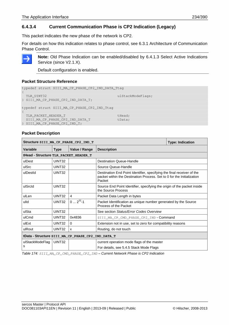
The Application Interface 234/390
sercos Master | Protocol API DOC081103API11EN | Revision 11 | English | 2013-09 | Released | Public © Hilscher, 2008-2013
6.4.3.4 Current Communication Phase is CP2 Indication (Legacy)
This packet indicates the new phase of the network is CP2.
For details on how this indication relates to phase control, see 6.3.1 Architecture of Communication Phase Control.
Note: Old Phase Indication can be enabled/disabled by 6.4.1.3 Select Active Indications Service (since V2.1.X).
Default configuration is enabled.
Packet Structure Reference
typedef struct SIII_MA_CP_PHASE_CP2_IND_DATA_Ttag { TLR_UINT32 ulStackModeFlags; } SIII_MA_CP_PHASE_CP2_IND_DATA_T; typedef struct SIII_MA_CP_PHASE_CP2_IND_Ttag { TLR_PACKET_HEADER_T tHead; SIII_MA_CP_PHASE_CP2_IND_DATA_T tData; } SIII_MA_CP_PHASE_CP2_IND_T;
Packet Description
Structure SIII_MA_CP_PHASE_CP2_IND_T Type: Indication
Variable Type Value / Range Description
tHead - Structure TLR_PACKET_HEADER_T
ulDest UINT32 Destination Queue-Handle
ulSrc UINT32 Source Queue-Handle
ulDestId UINT32 Destination End Point Identifier, specifying the final receiver of the packet within the Destination Process. Set to 0 for the Initialization Packet
ulSrcId UINT32 Source End Point Identifier, specifying the origin of the packet inside the Source Process
ulLen UINT32 4 Packet Data Length in bytes
ulId UINT32 0 ... 232-1 Packet Identification as unique number generated by the Source Process of the Packet
ulSta UINT32 See section Status/Error Codes Overview
ulCmd UINT32 0x4836 SIII_MA_CP_CMD_PHASE_CP2_IND - Command
ulExt UINT32 0 Extension not in use, set to zero for compatibility reasons
ulRout UINT32 x Routing, do not touch
tData - Structure SIII_MA_CP_PHASE_CP2_IND_DATA_T
ulStackModeFlags
UINT32 current operation mode flags of the master
For details, see 5.4.5 Stack Mode Flags
Table 174: SIII_MA_CP_CMD_PHASE_CP2_IND – Current Network Phase is CP2 Indication

The Application Interface 235/390
sercos Master | Protocol API DOC081103API11EN | Revision 11 | English | 2013-09 | Released | Public © Hilscher, 2008-2013
Packet Structure Reference
typedef struct SIII_MA_CP_PHASE_CP2_RES_Ttag { TLR_PACKET_HEADER_T tHead;
} SIII_MA_CP_PHASE_CP2_RES_T;
Packet Description
Structure SIII_MA_CP_PHASE_CP2_RES_T Type: Response
Variable Type Value / Range Description
Head - Structure TLR_PACKET_HEADER_T
ulDest UINT32 Destination queue handle, unchanged
ulSrc UINT32 Source queue handle, unchanged
ulDestId UINT32 Destination End Point Identifier, specifying the final receiver of the packet within the Destination Process. Set to 0 for the Initialization Packet
ulSrcId UINT32 Source End Point Identifier, specifying the origin of the packet inside the Source Process
ulLen UINT32 0 Packet Data Length in bytes
ulId UINT32 0 ... 232-1 Packet Identification, unchanged
ulSta UINT32 See section Status/Error Codes Overview
ulCmd UINT32 0x4837 SIII_MA_CP_CMD_PHASE_CP2_RES – Command
ulExt UINT32 0 Extension, reserved
ulRout UINT32 x Routing information, do not change
Table 175: SIII_MA_CP_CMD_PHASE_CP2_RES – Current Network Phase is CP2 Response

The Application Interface 236/390
sercos Master | Protocol API DOC081103API11EN | Revision 11 | English | 2013-09 | Released | Public © Hilscher, 2008-2013
6.4.3.5 Current Communication Phase is CP3 Indication (Legacy)
This packet indicates the new phase of the network is CP3.
For details on how this indication relates to phase control, see 6.3.1 Architecture of Communication Phase Control.
Note: Old Phase Indication can be enabled/disabled by 6.4.1.3 Select Active Indications Service (since V2.1.X).
Default configuration is enabled.
Packet Structure Reference
typedef struct SIII_MA_CP_PHASE_CP3_IND_Ttag { TLR_PACKET_HEADER_T tHead;
} SIII_MA_CP_PHASE_CP3_IND_T;
Packet Description
Structure SIII_MA_CP_PHASE_CP3_IND_T Type: Indication
Variable Type Value / Range Description
tHead - Structure TLR_PACKET_HEADER_T
ulDest UINT32 Destination Queue-Handle
ulSrc UINT32 Source Queue-Handle
ulDestId UINT32 Destination End Point Identifier, specifying the final receiver of the packet within the Destination Process. Set to 0 for the Initialization Packet
ulSrcId UINT32 Source End Point Identifier, specifying the origin of the packet inside the Source Process
ulLen UINT32 0 Packet Data Length in bytes
ulId UINT32 0 ... 232-1 Packet Identification as unique number generated by the Source Process of the Packet
ulSta UINT32 See section Status/Error Codes Overview
ulCmd UINT32 0x4838 SIII_MA_CP_CMD_PHASE_CP3_IND - Command
ulExt UINT32 0 Extension not in use, set to zero for compatibility reasons
ulRout UINT32 x Routing, do not touch
Table 176: SIII_MA_CP_CMD_PHASE_CP3_IND – Current Network Phase is CP3 Indication

The Application Interface 237/390
sercos Master | Protocol API DOC081103API11EN | Revision 11 | English | 2013-09 | Released | Public © Hilscher, 2008-2013
Packet Structure Reference
typedef struct SIII_MA_CP_PHASE_CP3_RES_Ttag { TLR_PACKET_HEADER_T tHead;
} SIII_MA_CP_PHASE_CP3_RES_T;
Packet Description
Structure SIII_MA_CP_PHASE_CP3_RES_T Type: Response
Variable Type Value / Range Description
Head - Structure TLR_PACKET_HEADER_T
ulDest UINT32 Destination queue handle, unchanged
ulSrc UINT32 Source queue handle, unchanged
ulDestId UINT32 Destination End Point Identifier, specifying the final receiver of the packet within the Destination Process. Set to 0 for the Initialization Packet
ulSrcId UINT32 Source End Point Identifier, specifying the origin of the packet inside the Source Process
ulLen UINT32 0 Packet Data Length in bytes
ulId UINT32 0 ... 232-1 Packet Identification, unchanged
ulSta UINT32 See section Status/Error Codes Overview
ulCmd UINT32 0x4839 SIII_MA_CP_CMD_PHASE_CP3_RES – Command
ulExt UINT32 0 Extension, reserved
ulRout UINT32 x Routing information, do not change
Table 177: SIII_MA_CP_CMD_PHASE_CP3_RES – Current Network Phase is CP3 Response
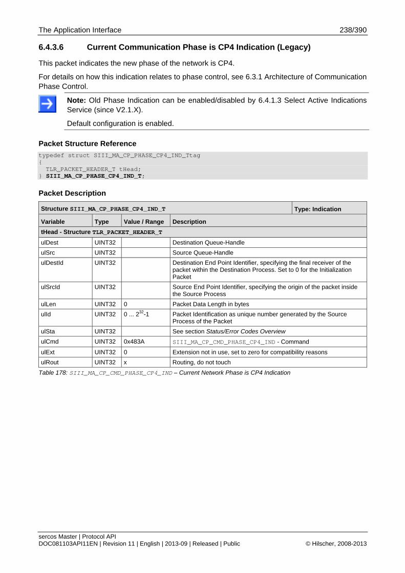
The Application Interface 238/390
sercos Master | Protocol API DOC081103API11EN | Revision 11 | English | 2013-09 | Released | Public © Hilscher, 2008-2013
6.4.3.6 Current Communication Phase is CP4 Indication (Legacy)
This packet indicates the new phase of the network is CP4.
For details on how this indication relates to phase control, see 6.3.1 Architecture of Communication Phase Control.
Note: Old Phase Indication can be enabled/disabled by 6.4.1.3 Select Active Indications Service (since V2.1.X).
Default configuration is enabled.
Packet Structure Reference
typedef struct SIII_MA_CP_PHASE_CP4_IND_Ttag { TLR_PACKET_HEADER_T tHead;
} SIII_MA_CP_PHASE_CP4_IND_T;
Packet Description
Structure SIII_MA_CP_PHASE_CP4_IND_T Type: Indication
Variable Type Value / Range Description
tHead - Structure TLR_PACKET_HEADER_T
ulDest UINT32 Destination Queue-Handle
ulSrc UINT32 Source Queue-Handle
ulDestId UINT32 Destination End Point Identifier, specifying the final receiver of the packet within the Destination Process. Set to 0 for the Initialization Packet
ulSrcId UINT32 Source End Point Identifier, specifying the origin of the packet inside the Source Process
ulLen UINT32 0 Packet Data Length in bytes
ulId UINT32 0 ... 232-1 Packet Identification as unique number generated by the Source Process of the Packet
ulSta UINT32 See section Status/Error Codes Overview
ulCmd UINT32 0x483A SIII_MA_CP_CMD_PHASE_CP4_IND - Command
ulExt UINT32 0 Extension not in use, set to zero for compatibility reasons
ulRout UINT32 x Routing, do not touch
Table 178: SIII_MA_CP_CMD_PHASE_CP4_IND – Current Network Phase is CP4 Indication

The Application Interface 239/390
sercos Master | Protocol API DOC081103API11EN | Revision 11 | English | 2013-09 | Released | Public © Hilscher, 2008-2013
Packet Structure Reference
typedef struct SIII_MA_CP_PHASE_CP4_RES_Ttag { TLR_PACKET_HEADER_T tHead;
} SIII_MA_CP_PHASE_CP4_RES_T;
Packet Description
Structure SIII_MA_CP_PHASE_CP4_RES_T Type: Response
Variable Type Value / Range Description
Head - Structure TLR_PACKET_HEADER_T
ulDest UINT32 Destination queue handle, unchanged
ulSrc UINT32 Source queue handle, unchanged
ulDestId UINT32 Destination End Point Identifier, specifying the final receiver of the packet within the Destination Process. Set to 0 for the Initialization Packet
ulSrcId UINT32 Source End Point Identifier, specifying the origin of the packet inside the Source Process
ulLen UINT32 0 Packet Data Length in bytes
ulId UINT32 0 ... 232-1 Packet Identification, unchanged
ulSta UINT32 See section Status/Error Codes Overview
ulCmd UINT32 0x483B SIII_MA_CP_CMD_PHASE_CP4_RES – Command
ulExt UINT32 0 Extension, reserved
ulRout UINT32 x Routing information, do not change
Table 179: SIII_MA_CP_CMD_PHASE_CP4_RES – Current Network Phase is CP4 Response
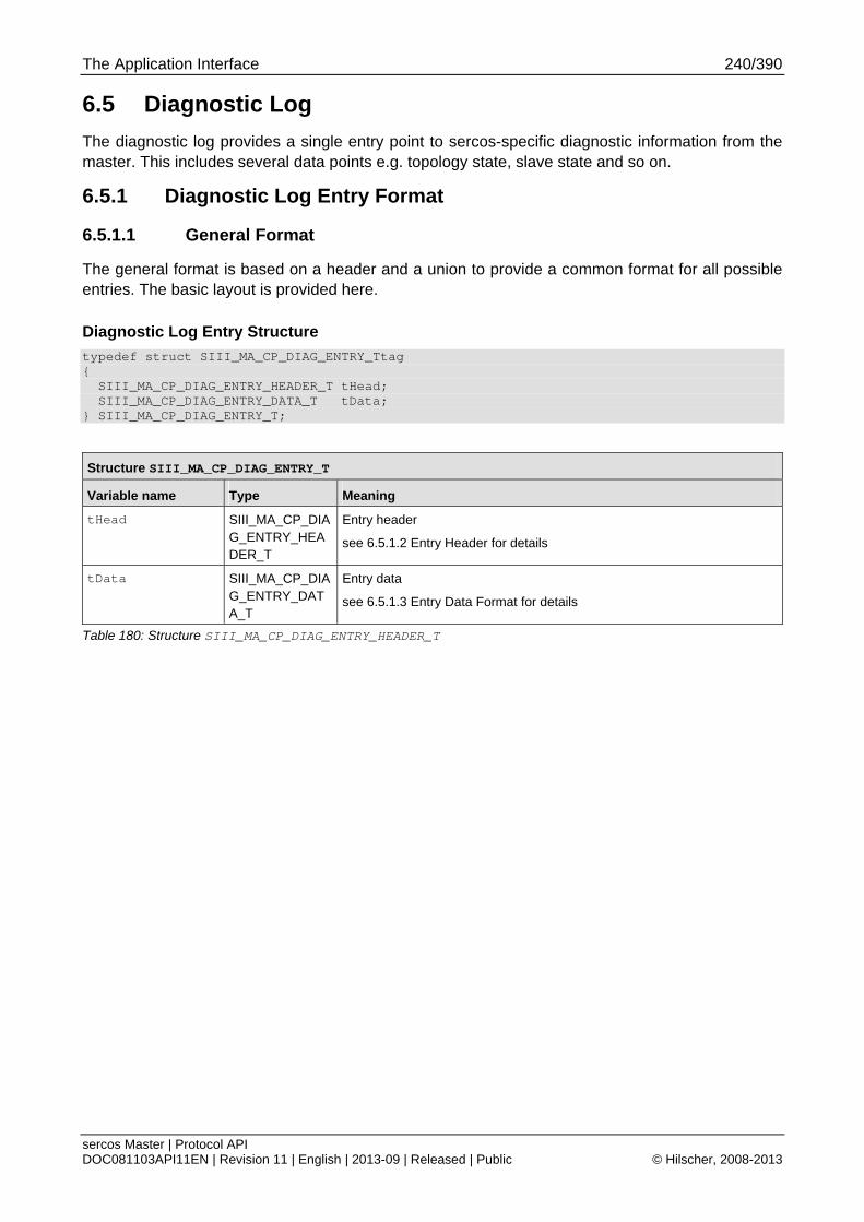
The Application Interface 240/390
sercos Master | Protocol API DOC081103API11EN | Revision 11 | English | 2013-09 | Released | Public © Hilscher, 2008-2013
6.5 Diagnostic Log
The diagnostic log provides a single entry point to sercos-specific diagnostic information from the master. This includes several data points e.g. topology state, slave state and so on.
6.5.1 Diagnostic Log Entry Format
6.5.1.1 General Format
The general format is based on a header and a union to provide a common format for all possible entries. The basic layout is provided here.
Diagnostic Log Entry Structure
typedef struct SIII_MA_CP_DIAG_ENTRY_Ttag { SIII_MA_CP_DIAG_ENTRY_HEADER_T tHead; SIII_MA_CP_DIAG_ENTRY_DATA_T tData; } SIII_MA_CP_DIAG_ENTRY_T;
Structure SIII_MA_CP_DIAG_ENTRY_T
Variable name Type Meaning
tHead SIII_MA_CP_DIAG_ENTRY_HEADER_T
Entry header
see 6.5.1.2 Entry Header for details
tData SIII_MA_CP_DIAG_ENTRY_DATA_T
Entry data
see 6.5.1.3 Entry Data Format for details
Table 180: Structure SIII_MA_CP_DIAG_ENTRY_HEADER_T
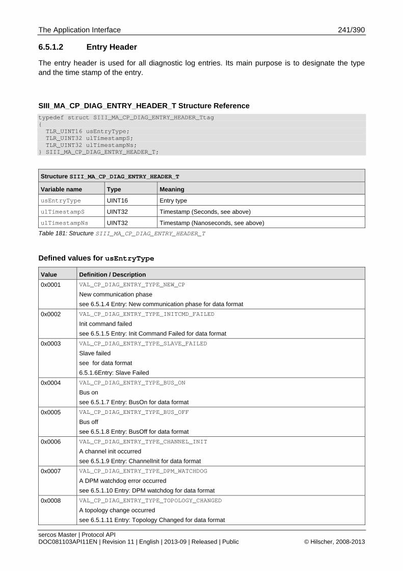
The Application Interface 241/390
sercos Master | Protocol API DOC081103API11EN | Revision 11 | English | 2013-09 | Released | Public © Hilscher, 2008-2013
6.5.1.2 Entry Header
The entry header is used for all diagnostic log entries. Its main purpose is to designate the type and the time stamp of the entry.
SIII_MA_CP_DIAG_ENTRY_HEADER_T Structure Reference
typedef struct SIII_MA_CP_DIAG_ENTRY_HEADER_Ttag { TLR_UINT16 usEntryType; TLR_UINT32 ulTimestampS; TLR_UINT32 ulTimestampNs; } SIII_MA_CP_DIAG_ENTRY_HEADER_T;
Structure SIII_MA_CP_DIAG_ENTRY_HEADER_T
Variable name Type Meaning
usEntryType UINT16 Entry type
ulTimestampS UINT32 Timestamp (Seconds, see above)
ulTimestampNs UINT32 Timestamp (Nanoseconds, see above)
Table 181: Structure SIII_MA_CP_DIAG_ENTRY_HEADER_T
Defined values for usEntryType
Value Definition / Description
0x0001 VAL_CP_DIAG_ENTRY_TYPE_NEW_CP
New communication phase
see 6.5.1.4 Entry: New communication phase for data format
0x0002 VAL_CP_DIAG_ENTRY_TYPE_INITCMD_FAILED
Init command failed
see 6.5.1.5 Entry: Init Command Failed for data format
0x0003 VAL_CP_DIAG_ENTRY_TYPE_SLAVE_FAILED
Slave failed
see for data format
6.5.1.6Entry: Slave Failed
0x0004 VAL_CP_DIAG_ENTRY_TYPE_BUS_ON
Bus on
see 6.5.1.7 Entry: BusOn for data format
0x0005 VAL_CP_DIAG_ENTRY_TYPE_BUS_OFF
Bus off
see 6.5.1.8 Entry: BusOff for data format
0x0006 VAL_CP_DIAG_ENTRY_TYPE_CHANNEL_INIT
A channel init occurred
see 6.5.1.9 Entry: ChannelInit for data format
0x0007 VAL_CP_DIAG_ENTRY_TYPE_DPM_WATCHDOG
A DPM watchdog error occurred
see 6.5.1.10 Entry: DPM watchdog for data format
0x0008 VAL_CP_DIAG_ENTRY_TYPE_TOPOLOGY_CHANGED
A topology change occurred
see 6.5.1.11 Entry: Topology Changed for data format
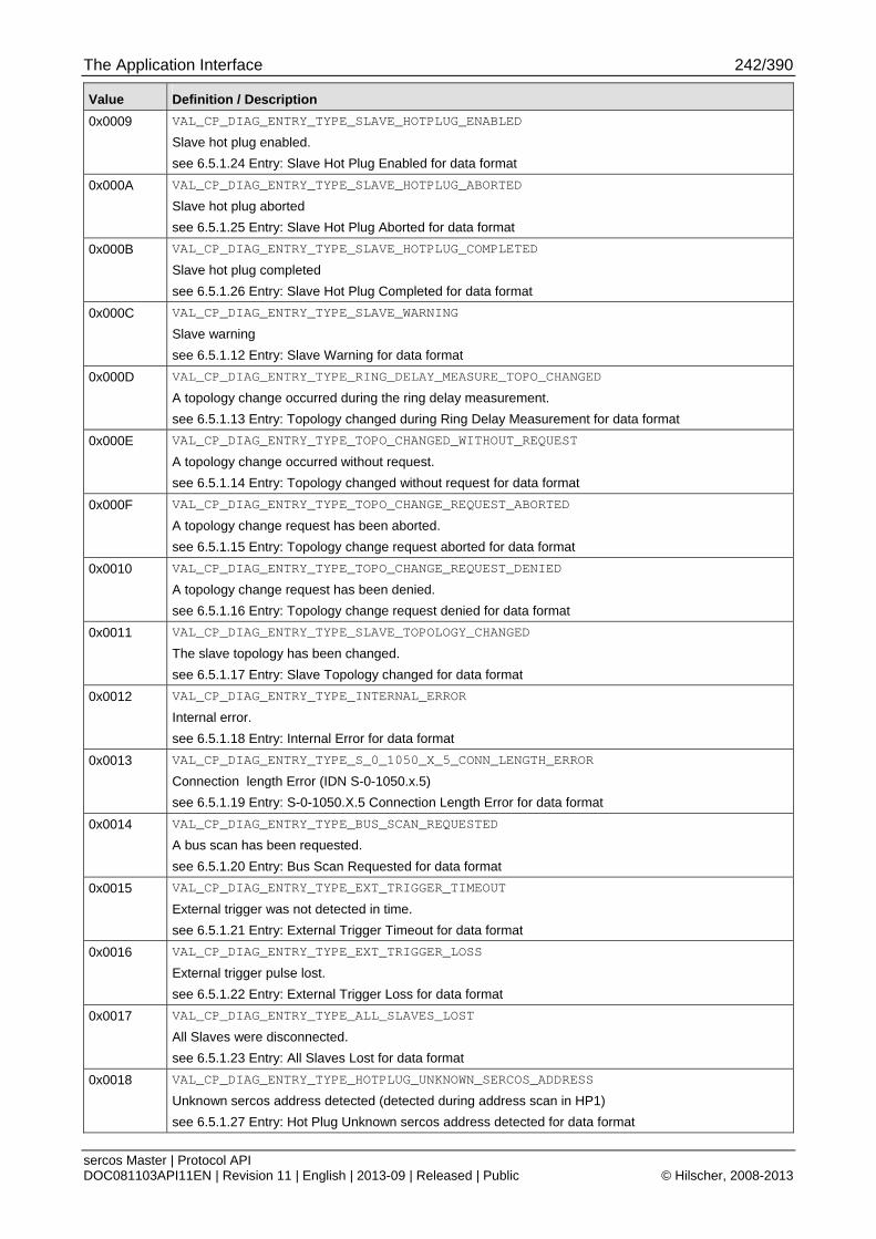
The Application Interface 242/390
sercos Master | Protocol API DOC081103API11EN | Revision 11 | English | 2013-09 | Released | Public © Hilscher, 2008-2013
Value Definition / Description
0x0009 VAL_CP_DIAG_ENTRY_TYPE_SLAVE_HOTPLUG_ENABLED
Slave hot plug enabled.
see 6.5.1.24 Entry: Slave Hot Plug Enabled for data format
0x000A VAL_CP_DIAG_ENTRY_TYPE_SLAVE_HOTPLUG_ABORTED
Slave hot plug aborted
see 6.5.1.25 Entry: Slave Hot Plug Aborted for data format
0x000B VAL_CP_DIAG_ENTRY_TYPE_SLAVE_HOTPLUG_COMPLETED
Slave hot plug completed
see 6.5.1.26 Entry: Slave Hot Plug Completed for data format
0x000C VAL_CP_DIAG_ENTRY_TYPE_SLAVE_WARNING
Slave warning
see 6.5.1.12 Entry: Slave Warning for data format
0x000D VAL_CP_DIAG_ENTRY_TYPE_RING_DELAY_MEASURE_TOPO_CHANGED
A topology change occurred during the ring delay measurement.
see 6.5.1.13 Entry: Topology changed during Ring Delay Measurement for data format
0x000E VAL_CP_DIAG_ENTRY_TYPE_TOPO_CHANGED_WITHOUT_REQUEST
A topology change occurred without request.
see 6.5.1.14 Entry: Topology changed without request for data format
0x000F VAL_CP_DIAG_ENTRY_TYPE_TOPO_CHANGE_REQUEST_ABORTED
A topology change request has been aborted.
see 6.5.1.15 Entry: Topology change request aborted for data format
0x0010 VAL_CP_DIAG_ENTRY_TYPE_TOPO_CHANGE_REQUEST_DENIED
A topology change request has been denied.
see 6.5.1.16 Entry: Topology change request denied for data format
0x0011 VAL_CP_DIAG_ENTRY_TYPE_SLAVE_TOPOLOGY_CHANGED
The slave topology has been changed.
see 6.5.1.17 Entry: Slave Topology changed for data format
0x0012 VAL_CP_DIAG_ENTRY_TYPE_INTERNAL_ERROR
Internal error.
see 6.5.1.18 Entry: Internal Error for data format
0x0013 VAL_CP_DIAG_ENTRY_TYPE_S_0_1050_X_5_CONN_LENGTH_ERROR
Connection length Error (IDN S-0-1050.x.5)
see 6.5.1.19 Entry: S-0-1050.X.5 Connection Length Error for data format
0x0014 VAL_CP_DIAG_ENTRY_TYPE_BUS_SCAN_REQUESTED
A bus scan has been requested.
see 6.5.1.20 Entry: Bus Scan Requested for data format
0x0015 VAL_CP_DIAG_ENTRY_TYPE_EXT_TRIGGER_TIMEOUT
External trigger was not detected in time.
see 6.5.1.21 Entry: External Trigger Timeout for data format
0x0016 VAL_CP_DIAG_ENTRY_TYPE_EXT_TRIGGER_LOSS
External trigger pulse lost.
see 6.5.1.22 Entry: External Trigger Loss for data format
0x0017 VAL_CP_DIAG_ENTRY_TYPE_ALL_SLAVES_LOST
All Slaves were disconnected.
see 6.5.1.23 Entry: All Slaves Lost for data format
0x0018 VAL_CP_DIAG_ENTRY_TYPE_HOTPLUG_UNKNOWN_SERCOS_ADDRESS
Unknown sercos address detected (detected during address scan in HP1)
see 6.5.1.27 Entry: Hot Plug Unknown sercos address detected for data format
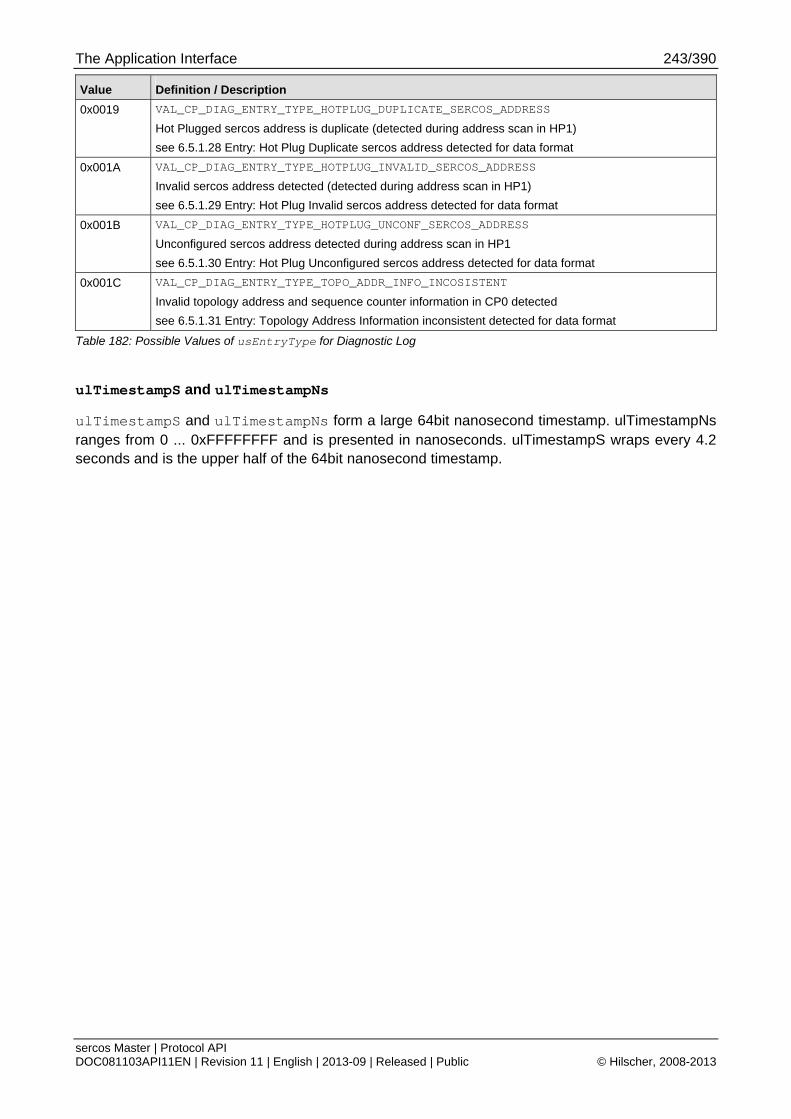
The Application Interface 243/390
sercos Master | Protocol API DOC081103API11EN | Revision 11 | English | 2013-09 | Released | Public © Hilscher, 2008-2013
Value Definition / Description
0x0019 VAL_CP_DIAG_ENTRY_TYPE_HOTPLUG_DUPLICATE_SERCOS_ADDRESS
Hot Plugged sercos address is duplicate (detected during address scan in HP1)
see 6.5.1.28 Entry: Hot Plug Duplicate sercos address detected for data format
0x001A VAL_CP_DIAG_ENTRY_TYPE_HOTPLUG_INVALID_SERCOS_ADDRESS
Invalid sercos address detected (detected during address scan in HP1)
see 6.5.1.29 Entry: Hot Plug Invalid sercos address detected for data format
0x001B VAL_CP_DIAG_ENTRY_TYPE_HOTPLUG_UNCONF_SERCOS_ADDRESS
Unconfigured sercos address detected during address scan in HP1
see 6.5.1.30 Entry: Hot Plug Unconfigured sercos address detected for data format
0x001C VAL_CP_DIAG_ENTRY_TYPE_TOPO_ADDR_INFO_INCOSISTENT
Invalid topology address and sequence counter information in CP0 detected
see 6.5.1.31 Entry: Topology Address Information inconsistent detected for data format
Table 182: Possible Values of usEntryType for Diagnostic Log
ulTimestampS and ulTimestampNs
ulTimestampS and ulTimestampNs form a large 64bit nanosecond timestamp. ulTimestampNs ranges from 0 ... 0xFFFFFFFF and is presented in nanoseconds. ulTimestampS wraps every 4.2 seconds and is the upper half of the 64bit nanosecond timestamp.

The Application Interface 244/390
sercos Master | Protocol API DOC081103API11EN | Revision 11 | English | 2013-09 | Released | Public © Hilscher, 2008-2013
6.5.1.3 Entry Data Format
The union referenced via tData contains all possible formats. The currently used format depends on the entry type (usEntryType) set in the header.
SIII_MA_CP_DIAG_ENTRY_DATA_T Structure Reference
typedef union SIII_MA_CP_DIAG_ENTRY_DATA_Ttag { SIII_MA_CP_DIAG_ENTRY_NEW_CP_T tNewCP; SIII_MA_CP_DIAG_ENTRY_INITCMD_FAILED_T tInitCmdFailed; SIII_MA_CP_DIAG_ENTRY_SLAVE_FAILED_T tSlaveFailed; SIII_MA_CP_DIAG_ENTRY_SLAVE_WARNING_T tSlaveWarning; SIII_MA_CP_DIAG_ENTRY_TOPOLOGY_CHANGED_T tTopologyChanged; SIII_MA_CP_DIAG_ENTRY_SLAVE_HOTPLUG_T tSlaveHotplug; SIII_MA_CP_DIAG_ENTRY_SLAVE_TOPOLOGY_CHANGED_T tSlaveTopologyChanged; SIII_MA_CP_DIAG_ENTRY_SLAVE_TOPOLOGY_CHANGE_ABORTED_T tSlaveTopologyChangeAborted; SIII_MA_CP_DIAG_ENTRY_INTERNAL_ERROR_T tInternalError; SIII_MA_CP_DIAG_ENTRY_S_0_1050_X_5_CONN_LENGTH_ERROR_T tConnLengthError; } SIII_MA_CP_DIAG_ENTRY_DATA_T;
The actual elements of the union will be detailed in following chapters.
Note: Sections may repeat certain structure references for clarity.
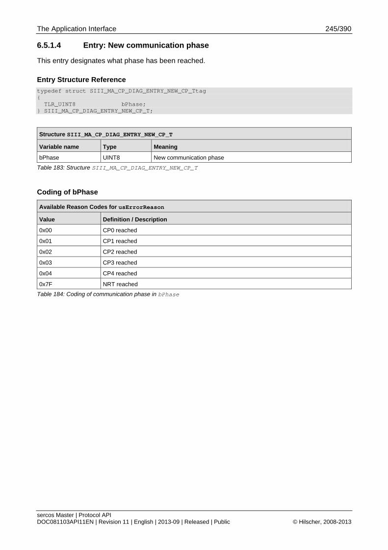
The Application Interface 245/390
sercos Master | Protocol API DOC081103API11EN | Revision 11 | English | 2013-09 | Released | Public © Hilscher, 2008-2013
6.5.1.4 Entry: New communication phase
This entry designates what phase has been reached.
Entry Structure Reference
typedef struct SIII_MA_CP_DIAG_ENTRY_NEW_CP_Ttag { TLR_UINT8 bPhase; } SIII_MA_CP_DIAG_ENTRY_NEW_CP_T;
Structure SIII_MA_CP_DIAG_ENTRY_NEW_CP_T
Variable name Type Meaning
bPhase UINT8 New communication phase
Table 183: Structure SIII_MA_CP_DIAG_ENTRY_NEW_CP_T
Coding of bPhase
Available Reason Codes for usErrorReason
Value Definition / Description
0x00 CP0 reached
0x01 CP1 reached
0x02 CP2 reached
0x03 CP3 reached
0x04 CP4 reached
0x7F NRT reached
Table 184: Coding of communication phase in bPhase
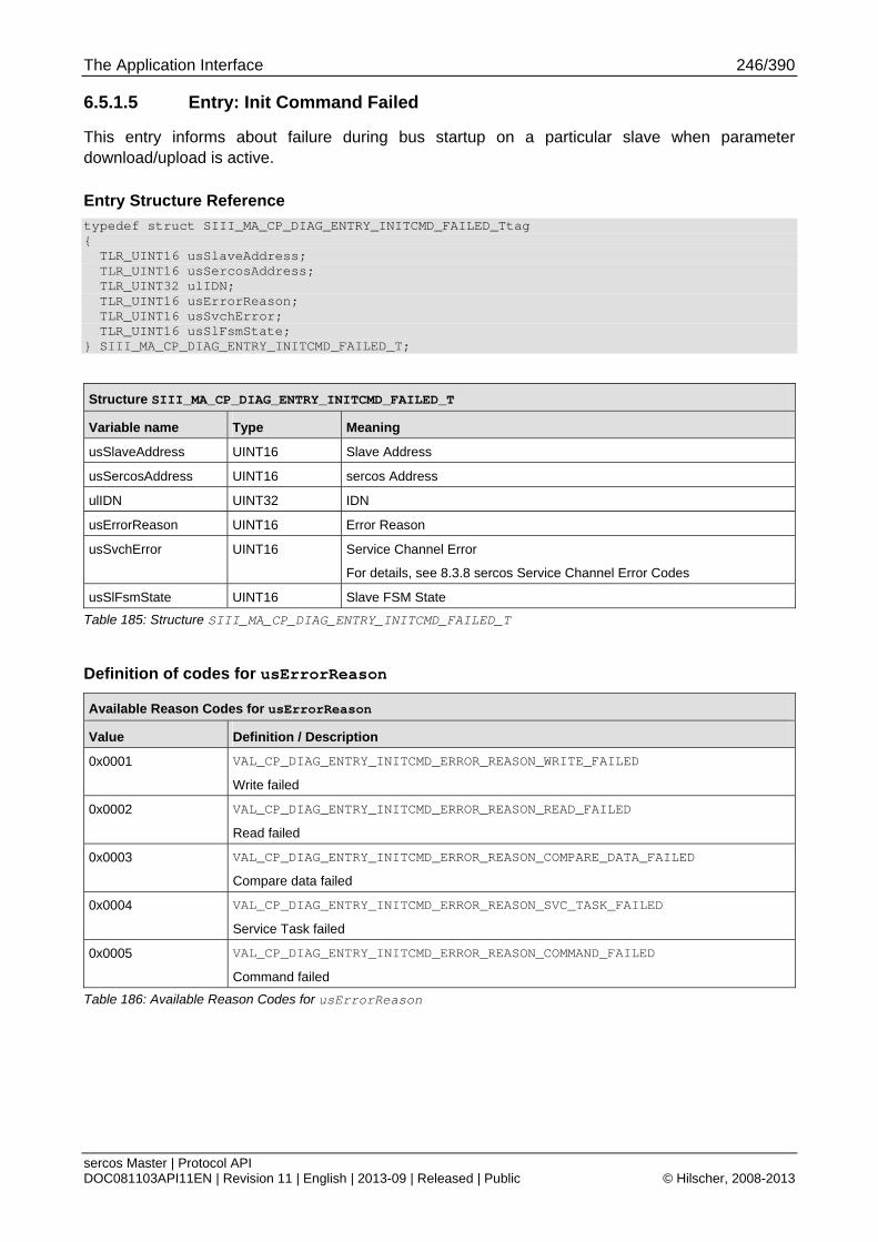
The Application Interface 246/390
sercos Master | Protocol API DOC081103API11EN | Revision 11 | English | 2013-09 | Released | Public © Hilscher, 2008-2013
6.5.1.5 Entry: Init Command Failed
This entry informs about failure during bus startup on a particular slave when parameter download/upload is active.
Entry Structure Reference
typedef struct SIII_MA_CP_DIAG_ENTRY_INITCMD_FAILED_Ttag { TLR_UINT16 usSlaveAddress; TLR_UINT16 usSercosAddress; TLR_UINT32 ulIDN; TLR_UINT16 usErrorReason; TLR_UINT16 usSvchError; TLR_UINT16 usSlFsmState; } SIII_MA_CP_DIAG_ENTRY_INITCMD_FAILED_T;
Structure SIII_MA_CP_DIAG_ENTRY_INITCMD_FAILED_T
Variable name Type Meaning
usSlaveAddress UINT16 Slave Address
usSercosAddress UINT16 sercos Address
ulIDN UINT32 IDN
usErrorReason UINT16 Error Reason
usSvchError UINT16 Service Channel Error
For details, see 8.3.8 sercos Service Channel Error Codes
usSlFsmState UINT16 Slave FSM State
Table 185: Structure SIII_MA_CP_DIAG_ENTRY_INITCMD_FAILED_T
Definition of codes for usErrorReason
Available Reason Codes for usErrorReason
Value Definition / Description
0x0001 VAL_CP_DIAG_ENTRY_INITCMD_ERROR_REASON_WRITE_FAILED
Write failed
0x0002 VAL_CP_DIAG_ENTRY_INITCMD_ERROR_REASON_READ_FAILED
Read failed
0x0003 VAL_CP_DIAG_ENTRY_INITCMD_ERROR_REASON_COMPARE_DATA_FAILED
Compare data failed
0x0004 VAL_CP_DIAG_ENTRY_INITCMD_ERROR_REASON_SVC_TASK_FAILED
Service Task failed
0x0005 VAL_CP_DIAG_ENTRY_INITCMD_ERROR_REASON_COMMAND_FAILED
Command failed
Table 186: Available Reason Codes for usErrorReason
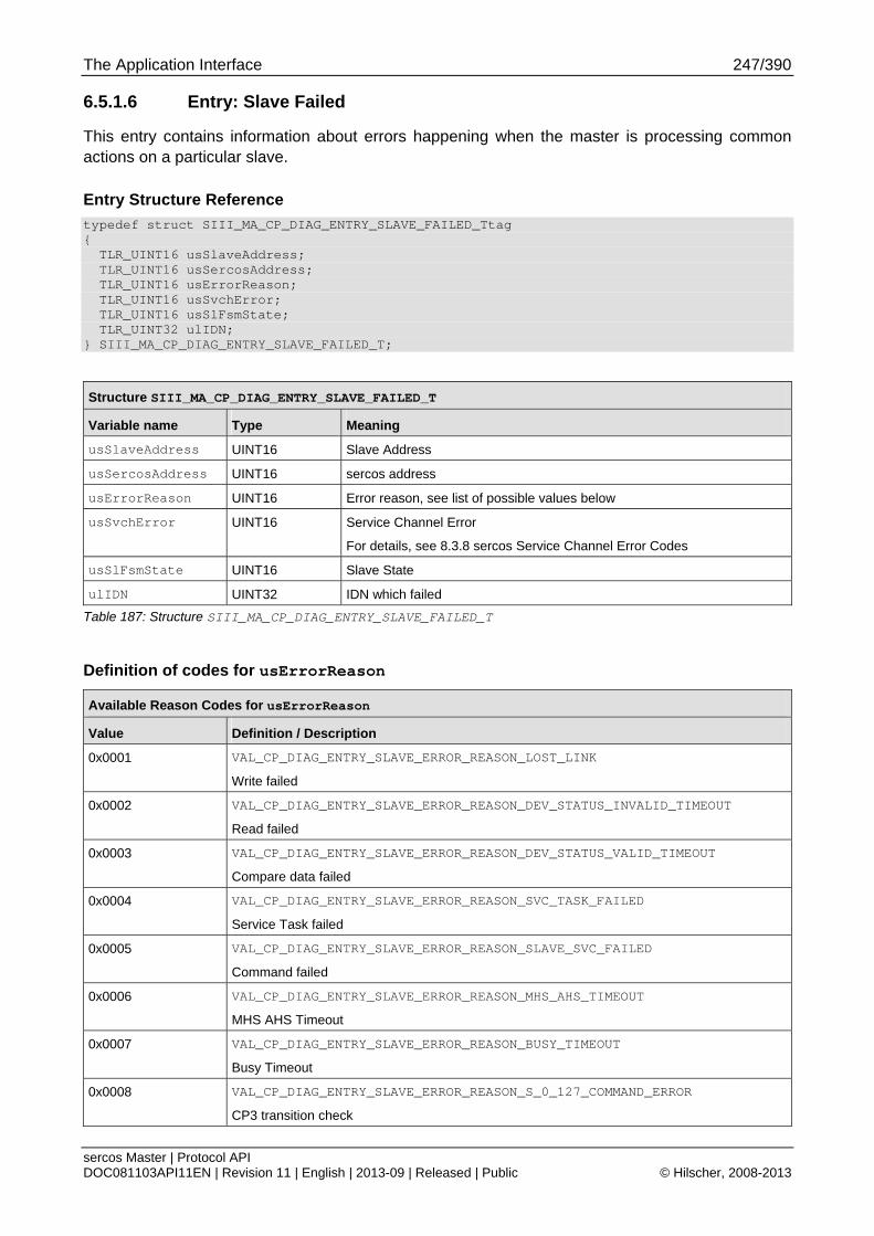
The Application Interface 247/390
sercos Master | Protocol API DOC081103API11EN | Revision 11 | English | 2013-09 | Released | Public © Hilscher, 2008-2013
6.5.1.6 Entry: Slave Failed
This entry contains information about errors happening when the master is processing common actions on a particular slave.
Entry Structure Reference
typedef struct SIII_MA_CP_DIAG_ENTRY_SLAVE_FAILED_Ttag { TLR_UINT16 usSlaveAddress; TLR_UINT16 usSercosAddress; TLR_UINT16 usErrorReason; TLR_UINT16 usSvchError; TLR_UINT16 usSlFsmState; TLR_UINT32 ulIDN; } SIII_MA_CP_DIAG_ENTRY_SLAVE_FAILED_T;
Structure SIII_MA_CP_DIAG_ENTRY_SLAVE_FAILED_T
Variable name Type Meaning
usSlaveAddress UINT16 Slave Address
usSercosAddress UINT16 sercos address
usErrorReason UINT16 Error reason, see list of possible values below
usSvchError UINT16 Service Channel Error
For details, see 8.3.8 sercos Service Channel Error Codes
usSlFsmState UINT16 Slave State
ulIDN UINT32 IDN which failed
Table 187: Structure SIII_MA_CP_DIAG_ENTRY_SLAVE_FAILED_T
Definition of codes for usErrorReason
Available Reason Codes for usErrorReason
Value Definition / Description
0x0001 VAL_CP_DIAG_ENTRY_SLAVE_ERROR_REASON_LOST_LINK
Write failed
0x0002 VAL_CP_DIAG_ENTRY_SLAVE_ERROR_REASON_DEV_STATUS_INVALID_TIMEOUT
Read failed
0x0003 VAL_CP_DIAG_ENTRY_SLAVE_ERROR_REASON_DEV_STATUS_VALID_TIMEOUT
Compare data failed
0x0004 VAL_CP_DIAG_ENTRY_SLAVE_ERROR_REASON_SVC_TASK_FAILED
Service Task failed
0x0005 VAL_CP_DIAG_ENTRY_SLAVE_ERROR_REASON_SLAVE_SVC_FAILED
Command failed
0x0006 VAL_CP_DIAG_ENTRY_SLAVE_ERROR_REASON_MHS_AHS_TIMEOUT
MHS AHS Timeout
0x0007 VAL_CP_DIAG_ENTRY_SLAVE_ERROR_REASON_BUSY_TIMEOUT
Busy Timeout
0x0008 VAL_CP_DIAG_ENTRY_SLAVE_ERROR_REASON_S_0_127_COMMAND_ERROR
CP3 transition check
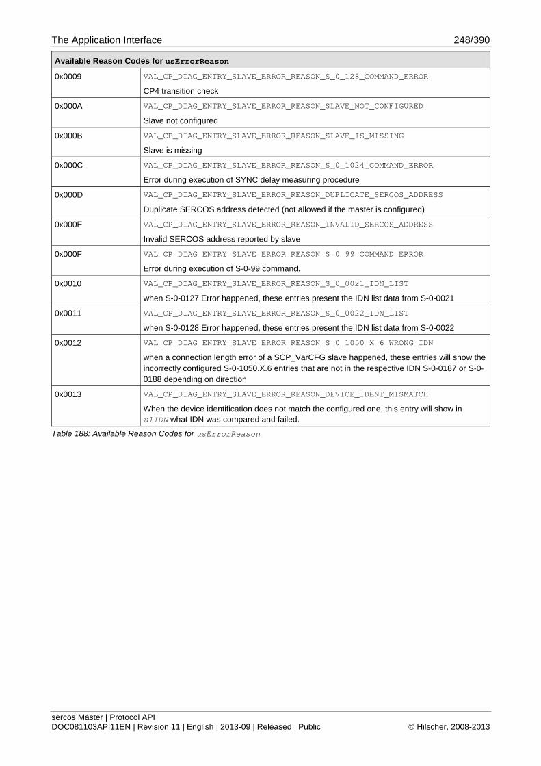
The Application Interface 248/390
sercos Master | Protocol API DOC081103API11EN | Revision 11 | English | 2013-09 | Released | Public © Hilscher, 2008-2013
Available Reason Codes for usErrorReason
0x0009 VAL_CP_DIAG_ENTRY_SLAVE_ERROR_REASON_S_0_128_COMMAND_ERROR
CP4 transition check
0x000A VAL_CP_DIAG_ENTRY_SLAVE_ERROR_REASON_SLAVE_NOT_CONFIGURED
Slave not configured
0x000B VAL_CP_DIAG_ENTRY_SLAVE_ERROR_REASON_SLAVE_IS_MISSING
Slave is missing
0x000C VAL_CP_DIAG_ENTRY_SLAVE_ERROR_REASON_S_0_1024_COMMAND_ERROR
Error during execution of SYNC delay measuring procedure
0x000D VAL_CP_DIAG_ENTRY_SLAVE_ERROR_REASON_DUPLICATE_SERCOS_ADDRESS
Duplicate SERCOS address detected (not allowed if the master is configured)
0x000E VAL_CP_DIAG_ENTRY_SLAVE_ERROR_REASON_INVALID_SERCOS_ADDRESS
Invalid SERCOS address reported by slave
0x000F VAL_CP_DIAG_ENTRY_SLAVE_ERROR_REASON_S_0_99_COMMAND_ERROR
Error during execution of S-0-99 command.
0x0010 VAL_CP_DIAG_ENTRY_SLAVE_ERROR_REASON_S_0_0021_IDN_LIST
when S-0-0127 Error happened, these entries present the IDN list data from S-0-0021
0x0011 VAL_CP_DIAG_ENTRY_SLAVE_ERROR_REASON_S_0_0022_IDN_LIST
when S-0-0128 Error happened, these entries present the IDN list data from S-0-0022
0x0012 VAL_CP_DIAG_ENTRY_SLAVE_ERROR_REASON_S_0_1050_X_6_WRONG_IDN
when a connection length error of a SCP_VarCFG slave happened, these entries will show the incorrectly configured S-0-1050.X.6 entries that are not in the respective IDN S-0-0187 or S-0-0188 depending on direction
0x0013 VAL_CP_DIAG_ENTRY_SLAVE_ERROR_REASON_DEVICE_IDENT_MISMATCH
When the device identification does not match the configured one, this entry will show in ulIDN what IDN was compared and failed.
Table 188: Available Reason Codes for usErrorReason
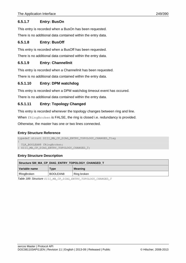
The Application Interface 249/390
sercos Master | Protocol API DOC081103API11EN | Revision 11 | English | 2013-09 | Released | Public © Hilscher, 2008-2013
6.5.1.7 Entry: BusOn
This entry is recorded when a BusOn has been requested.
There is no additional data contained within the entry data.
6.5.1.8 Entry: BusOff
This entry is recorded when a BusOff has been requested.
There is no additional data contained within the entry data.
6.5.1.9 Entry: ChannelInit
This entry is recorded when a ChannelInit has been requested.
There is no additional data contained within the entry data.
6.5.1.10 Entry: DPM watchdog
This entry is recorded when a DPM watchdog timeout event has occured.
There is no additional data contained within the entry data.
6.5.1.11 Entry: Topology Changed
This entry is recorded whenever the topology changes between ring and line.
When fRingBroken is FALSE, the ring is closed i.e. redundancy is provided.
Otherwise, the master has one or two lines connected.
Entry Structure Reference
typedef struct SIII_MA_CP_DIAG_ENTRY_TOPOLOGY_CHANGED_Ttag { TLR_BOOLEAN8 fRingBroken; } SIII_MA_CP_DIAG_ENTRY_TOPOLOGY_CHANGED_T;
Entry Structure Description
Structure SIII_MA_CP_DIAG_ENTRY_TOPOLOGY_CHANGED_T
Variable name Type Meaning
fRingBroken BOOLEAN8 Ring broken
Table 189: Structure SIII_MA_CP_DIAG_ENTRY_TOPOLOGY_CHANGED_T
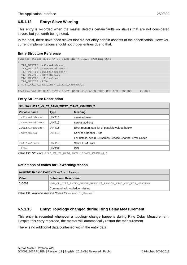
The Application Interface 250/390
sercos Master | Protocol API DOC081103API11EN | Revision 11 | English | 2013-09 | Released | Public © Hilscher, 2008-2013
6.5.1.12 Entry: Slave Warning
This entry is recorded when the master detects certain faults on slaves that are not considered severe but yet worth being noted.
In the past, there have been slaves that did not obey certain aspects of the specification. However, current implementations should not trigger entries due to that.
Entry Structure Reference
typedef struct SIII_MA_CP_DIAG_ENTRY_SLAVE_WARNING_Ttag { TLR_UINT16 usSlaveAddress; TLR_UINT16 usSercosAddress; TLR_UINT16 usWarningReason; TLR_UINT16 usSvchError; TLR_UINT16 usSlFsmState; TLR_UINT32 ulIDN; } SIII_MA_CP_DIAG_ENTRY_SLAVE_WARNING_T; #define VAL_CP_DIAG_ENTRY_SLAVE_WARNING_REASON_PROC_CMD_ACK_MISSING 0x0001
Entry Structure Description
Structure SIII_MA_CP_DIAG_ENTRY_SLAVE_WARNING_T
Variable name Type Meaning
usSlaveAddress UINT16 slave address
usSercosAddress UINT16 sercos address
usWarningReason UINT16 Error reason, see list of possible values below
usSvchError UINT16 Service Channel Error
For details, see 8.3.8 sercos Service Channel Error Codes
usSlFsmState UINT16 Slave FSM State
ulIDN UINT32 IDN
Table 190: Structure SIII_MA_CP_DIAG_ENTRY_SLAVE_WARNING_T
Definitions of codes for usWarningReason
Available Reason Codes for usErrorReason
Value Definition / Description
0x0001 VAL_CP_DIAG_ENTRY_SLAVE_WARNING_REASON_PROC_CMD_ACK_MISSING
Command acknowledge missing
Table 191: Available Reason Codes for usWarningReason
6.5.1.13 Entry: Topology changed during Ring Delay Measurement
This entry is recorded whenever a topology change happens during Ring Delay Measurement. Despite this entry recorded, the master will automatically restart the measurement.
There is no additional data contained within the entry data.
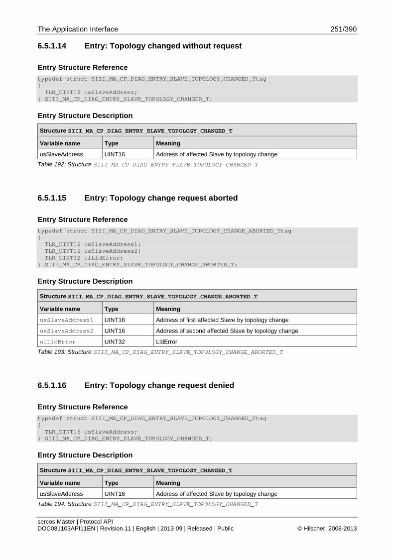
The Application Interface 251/390
sercos Master | Protocol API DOC081103API11EN | Revision 11 | English | 2013-09 | Released | Public © Hilscher, 2008-2013
6.5.1.14 Entry: Topology changed without request
Entry Structure Reference
typedef struct SIII_MA_CP_DIAG_ENTRY_SLAVE_TOPOLOGY_CHANGED_Ttag { TLR_UINT16 usSlaveAddress; } SIII_MA_CP_DIAG_ENTRY_SLAVE_TOPOLOGY_CHANGED_T;
Entry Structure Description
Structure SIII_MA_CP_DIAG_ENTRY_SLAVE_TOPOLOGY_CHANGED_T
Variable name Type Meaning
usSlaveAddress UINT16 Address of affected Slave by topology change
Table 192: Structure SIII_MA_CP_DIAG_ENTRY_SLAVE_TOPOLOGY_CHANGED_T
6.5.1.15 Entry: Topology change request aborted
Entry Structure Reference
typedef struct SIII_MA_CP_DIAG_ENTRY_SLAVE_TOPOLOGY_CHANGE_ABORTED_Ttag { TLR_UINT16 usSlaveAddress1; TLR_UINT16 usSlaveAddress2; TLR_UINT32 ulLldError; } SIII_MA_CP_DIAG_ENTRY_SLAVE_TOPOLOGY_CHANGE_ABORTED_T;
Entry Structure Description
Structure SIII_MA_CP_DIAG_ENTRY_SLAVE_TOPOLOGY_CHANGE_ABORTED_T
Variable name Type Meaning
usSlaveAddress1 UINT16 Address of first affected Slave by topology change
usSlaveAddress2 UINT16 Address of second affected Slave by topology change
ulLldError UINT32 LldError
Table 193: Structure SIII_MA_CP_DIAG_ENTRY_SLAVE_TOPOLOGY_CHANGE_ABORTED_T
6.5.1.16 Entry: Topology change request denied
Entry Structure Reference
typedef struct SIII_MA_CP_DIAG_ENTRY_SLAVE_TOPOLOGY_CHANGED_Ttag { TLR_UINT16 usSlaveAddress; } SIII_MA_CP_DIAG_ENTRY_SLAVE_TOPOLOGY_CHANGED_T;
Entry Structure Description
Structure SIII_MA_CP_DIAG_ENTRY_SLAVE_TOPOLOGY_CHANGED_T
Variable name Type Meaning
usSlaveAddress UINT16 Address of affected Slave by topology change
Table 194: Structure SIII_MA_CP_DIAG_ENTRY_SLAVE_TOPOLOGY_CHANGED_T
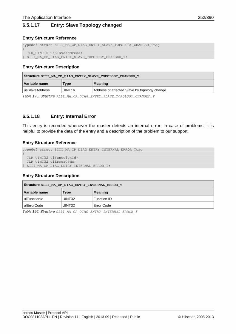
The Application Interface 252/390
sercos Master | Protocol API DOC081103API11EN | Revision 11 | English | 2013-09 | Released | Public © Hilscher, 2008-2013
6.5.1.17 Entry: Slave Topology changed
Entry Structure Reference
typedef struct SIII_MA_CP_DIAG_ENTRY_SLAVE_TOPOLOGY_CHANGED_Ttag { TLR_UINT16 usSlaveAddress; } SIII_MA_CP_DIAG_ENTRY_SLAVE_TOPOLOGY_CHANGED_T;
Entry Structure Description
Structure SIII_MA_CP_DIAG_ENTRY_SLAVE_TOPOLOGY_CHANGED_T
Variable name Type Meaning
usSlaveAddress UINT16 Address of affected Slave by topology change
Table 195: Structure SIII_MA_CP_DIAG_ENTRY_SLAVE_TOPOLOGY_CHANGED_T
6.5.1.18 Entry: Internal Error
This entry is recorded whenever the master detects an internal error. In case of problems, it is helpful to provide the data of the entry and a description of the problem to our support.
Entry Structure Reference
typedef struct SIII_MA_CP_DIAG_ENTRY_INTERNAL_ERROR_Ttag { TLR_UINT32 ulFunctionId; TLR_UINT32 ulErrorCode; } SIII_MA_CP_DIAG_ENTRY_INTERNAL_ERROR_T;
Entry Structure Description
Structure SIII_MA_CP_DIAG_ENTRY_INTERNAL_ERROR_T
Variable name Type Meaning
ulFunctionId UINT32 Function ID
ulErrorCode UINT32 Error Code
Table 196: Structure SIII_MA_CP_DIAG_ENTRY_INTERNAL_ERROR_T
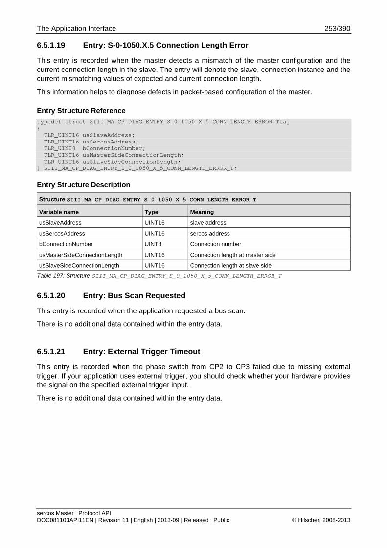
The Application Interface 253/390
sercos Master | Protocol API DOC081103API11EN | Revision 11 | English | 2013-09 | Released | Public © Hilscher, 2008-2013
6.5.1.19 Entry: S-0-1050.X.5 Connection Length Error
This entry is recorded when the master detects a mismatch of the master configuration and the current connection length in the slave. The entry will denote the slave, connection instance and the current mismatching values of expected and current connection length.
This information helps to diagnose defects in packet-based configuration of the master.
Entry Structure Reference
typedef struct SIII_MA_CP_DIAG_ENTRY_S_0_1050_X_5_CONN_LENGTH_ERROR_Ttag { TLR_UINT16 usSlaveAddress; TLR_UINT16 usSercosAddress; TLR_UINT8 bConnectionNumber; TLR_UINT16 usMasterSideConnectionLength; TLR_UINT16 usSlaveSideConnectionLength; } SIII_MA_CP_DIAG_ENTRY_S_0_1050_X_5_CONN_LENGTH_ERROR_T;
Entry Structure Description
Structure SIII_MA_CP_DIAG_ENTRY_S_0_1050_X_5_CONN_LENGTH_ERROR_T
Variable name Type Meaning
usSlaveAddress UINT16 slave address
usSercosAddress UINT16 sercos address
bConnectionNumber UINT8 Connection number
usMasterSideConnectionLength UINT16 Connection length at master side
usSlaveSideConnectionLength UINT16 Connection length at slave side
Table 197: Structure SIII_MA_CP_DIAG_ENTRY_S_0_1050_X_5_CONN_LENGTH_ERROR_T
6.5.1.20 Entry: Bus Scan Requested
This entry is recorded when the application requested a bus scan.
There is no additional data contained within the entry data.
6.5.1.21 Entry: External Trigger Timeout
This entry is recorded when the phase switch from CP2 to CP3 failed due to missing external trigger. If your application uses external trigger, you should check whether your hardware provides the signal on the specified external trigger input.
There is no additional data contained within the entry data.
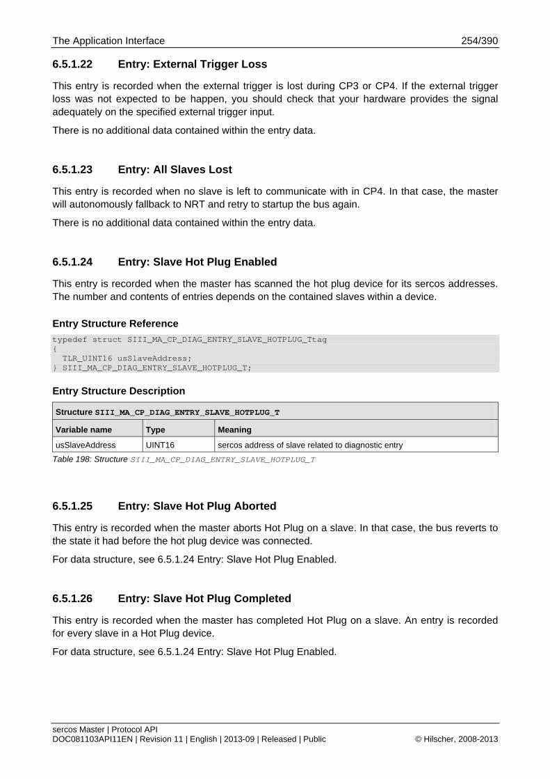
The Application Interface 254/390
sercos Master | Protocol API DOC081103API11EN | Revision 11 | English | 2013-09 | Released | Public © Hilscher, 2008-2013
6.5.1.22 Entry: External Trigger Loss
This entry is recorded when the external trigger is lost during CP3 or CP4. If the external trigger loss was not expected to be happen, you should check that your hardware provides the signal adequately on the specified external trigger input.
There is no additional data contained within the entry data.
6.5.1.23 Entry: All Slaves Lost
This entry is recorded when no slave is left to communicate with in CP4. In that case, the master will autonomously fallback to NRT and retry to startup the bus again.
There is no additional data contained within the entry data.
6.5.1.24 Entry: Slave Hot Plug Enabled
This entry is recorded when the master has scanned the hot plug device for its sercos addresses. The number and contents of entries depends on the contained slaves within a device.
Entry Structure Reference
typedef struct SIII_MA_CP_DIAG_ENTRY_SLAVE_HOTPLUG_Ttag { TLR_UINT16 usSlaveAddress; } SIII_MA_CP_DIAG_ENTRY_SLAVE_HOTPLUG_T;
Entry Structure Description
Structure SIII_MA_CP_DIAG_ENTRY_SLAVE_HOTPLUG_T
Variable name Type Meaning
usSlaveAddress UINT16 sercos address of slave related to diagnostic entry
Table 198: Structure SIII_MA_CP_DIAG_ENTRY_SLAVE_HOTPLUG_T
6.5.1.25 Entry: Slave Hot Plug Aborted
This entry is recorded when the master aborts Hot Plug on a slave. In that case, the bus reverts to the state it had before the hot plug device was connected.
For data structure, see 6.5.1.24 Entry: Slave Hot Plug Enabled.
6.5.1.26 Entry: Slave Hot Plug Completed
This entry is recorded when the master has completed Hot Plug on a slave. An entry is recorded for every slave in a Hot Plug device.
For data structure, see 6.5.1.24 Entry: Slave Hot Plug Enabled.
The Application Interface 255/390
sercos Master | Protocol API DOC081103API11EN | Revision 11 | English | 2013-09 | Released | Public © Hilscher, 2008-2013
6.5.1.27 Entry: Hot Plug Unknown sercos address detected
This entry is recorded when an unknown sercos address has been encountered during hot plug address scan.
For data structure, see 6.5.1.24 Entry: Slave Hot Plug Enabled.
6.5.1.28 Entry: Hot Plug Duplicate sercos address detected
This entry is recorded when a duplicate sercos address has been encountered during hot plug address scan.
For data structure, see 6.5.1.24 Entry: Slave Hot Plug Enabled.
6.5.1.29 Entry: Hot Plug Invalid sercos address detected
This entry is recorded when an invalid sercos address has been encountered during hot plug address scan.
For data structure, see 6.5.1.24 Entry: Slave Hot Plug Enabled.
6.5.1.30 Entry: Hot Plug Unconfigured sercos address detected
This entry is recorded when an unconfigured sercos address has been encountered during hot plug address scan.
For data structure, see 6.5.1.24 Entry: Slave Hot Plug Enabled.
6.5.1.31 Entry: Topology Address Information inconsistent detected
This entry is recorded when a slave is not correctly handling sequence counters in CP0.
There is no additional data contained within the entry data.
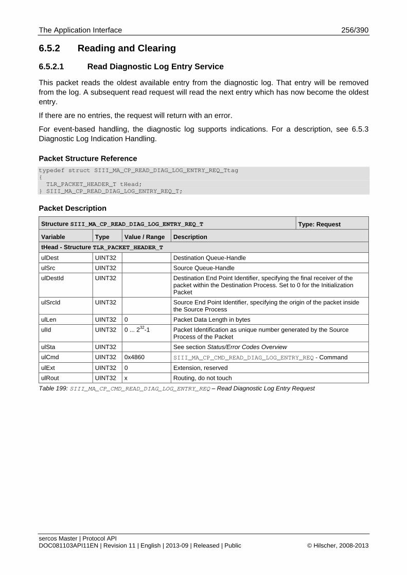
The Application Interface 256/390
sercos Master | Protocol API DOC081103API11EN | Revision 11 | English | 2013-09 | Released | Public © Hilscher, 2008-2013
6.5.2 Reading and Clearing
6.5.2.1 Read Diagnostic Log Entry Service
This packet reads the oldest available entry from the diagnostic log. That entry will be removed from the log. A subsequent read request will read the next entry which has now become the oldest entry.
If there are no entries, the request will return with an error.
For event-based handling, the diagnostic log supports indications. For a description, see 6.5.3 Diagnostic Log Indication Handling.
Packet Structure Reference
typedef struct SIII_MA_CP_READ_DIAG_LOG_ENTRY_REQ_Ttag { TLR_PACKET_HEADER_T tHead; } SIII_MA_CP_READ_DIAG_LOG_ENTRY_REQ_T;
Packet Description
Structure SIII_MA_CP_READ_DIAG_LOG_ENTRY_REQ_T Type: Request
Variable Type Value / Range Description
tHead - Structure TLR_PACKET_HEADER_T
ulDest UINT32 Destination Queue-Handle
ulSrc UINT32 Source Queue-Handle
ulDestId UINT32 Destination End Point Identifier, specifying the final receiver of the packet within the Destination Process. Set to 0 for the Initialization Packet
ulSrcId UINT32 Source End Point Identifier, specifying the origin of the packet inside the Source Process
ulLen UINT32 0 Packet Data Length in bytes
ulId UINT32 0 ... 232-1 Packet Identification as unique number generated by the Source Process of the Packet
ulSta UINT32 See section Status/Error Codes Overview
ulCmd UINT32 0x4860 SIII_MA_CP_CMD_READ_DIAG_LOG_ENTRY_REQ - Command
ulExt UINT32 0 Extension, reserved
ulRout UINT32 x Routing, do not touch
Table 199: SIII_MA_CP_CMD_READ_DIAG_LOG_ENTRY_REQ – Read Diagnostic Log Entry Request
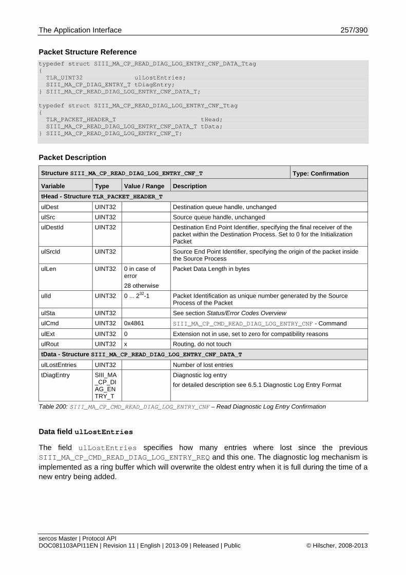
The Application Interface 257/390
sercos Master | Protocol API DOC081103API11EN | Revision 11 | English | 2013-09 | Released | Public © Hilscher, 2008-2013
Packet Structure Reference
typedef struct SIII_MA_CP_READ_DIAG_LOG_ENTRY_CNF_DATA_Ttag { TLR_UINT32 ulLostEntries; SIII_MA_CP_DIAG_ENTRY_T tDiagEntry; } SIII_MA_CP_READ_DIAG_LOG_ENTRY_CNF_DATA_T; typedef struct SIII_MA_CP_READ_DIAG_LOG_ENTRY_CNF_Ttag { TLR_PACKET_HEADER_T tHead; SIII_MA_CP_READ_DIAG_LOG_ENTRY_CNF_DATA_T tData; } SIII_MA_CP_READ_DIAG_LOG_ENTRY_CNF_T;
Packet Description
Structure SIII_MA_CP_READ_DIAG_LOG_ENTRY_CNF_T Type: Confirmation
Variable Type Value / Range Description
tHead - Structure TLR_PACKET_HEADER_T
ulDest UINT32 Destination queue handle, unchanged
ulSrc UINT32 Source queue handle, unchanged
ulDestId UINT32 Destination End Point Identifier, specifying the final receiver of the packet within the Destination Process. Set to 0 for the Initialization Packet
ulSrcId UINT32 Source End Point Identifier, specifying the origin of the packet inside the Source Process
ulLen UINT32 0 in case of error
28 otherwise
Packet Data Length in bytes
ulId UINT32 0 ... 232-1 Packet Identification as unique number generated by the Source Process of the Packet
ulSta UINT32 See section Status/Error Codes Overview
ulCmd UINT32 0x4861 SIII_MA_CP_CMD_READ_DIAG_LOG_ENTRY_CNF - Command
ulExt UINT32 0 Extension not in use, set to zero for compatibility reasons
ulRout UINT32 x Routing, do not touch
tData - Structure SIII_MA_CP_READ_DIAG_LOG_ENTRY_CNF_DATA_T
ulLostEntries UINT32 Number of lost entries
tDiagEntry SIII_MA_CP_DIAG_ENTRY_T
Diagnostic log entry
for detailed description see 6.5.1 Diagnostic Log Entry Format
Table 200: SIII_MA_CP_CMD_READ_DIAG_LOG_ENTRY_CNF – Read Diagnostic Log Entry Confirmation
Data field ulLostEntries
The field ulLostEntries specifies how many entries where lost since the previous SIII_MA_CP_CMD_READ_DIAG_LOG_ENTRY_REQ and this one. The diagnostic log mechanism is implemented as a ring buffer which will overwrite the oldest entry when it is full during the time of a new entry being added.
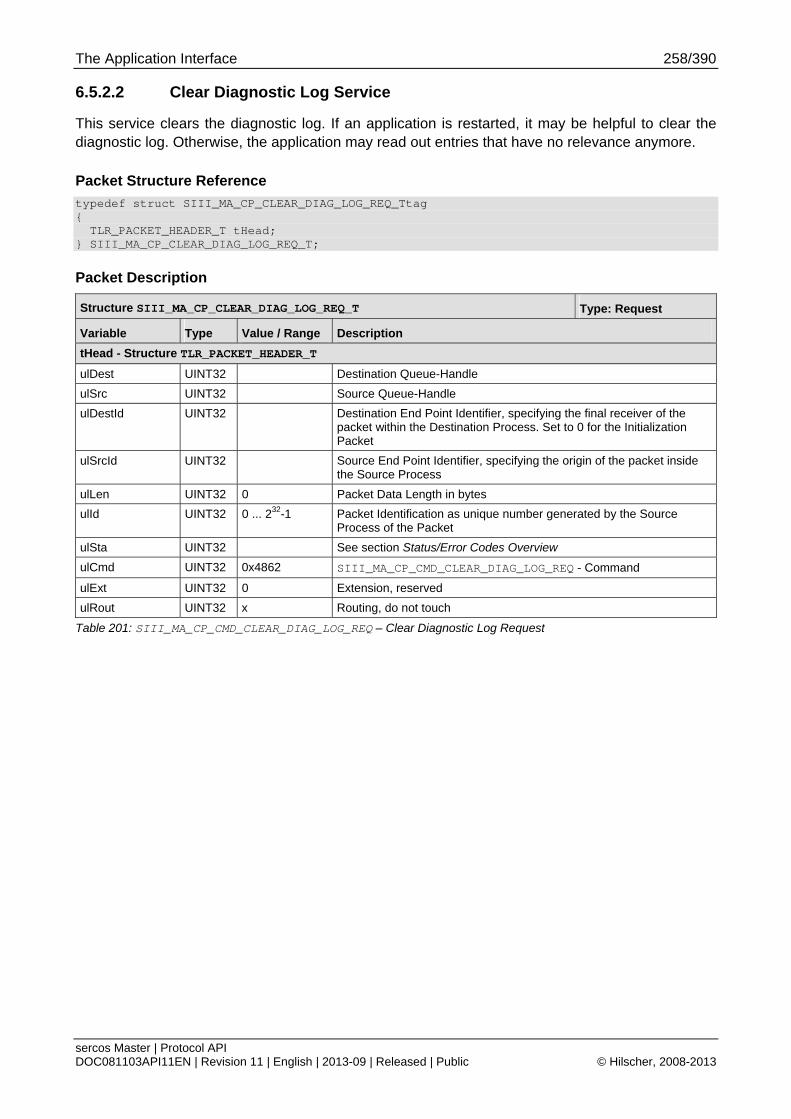
The Application Interface 258/390
sercos Master | Protocol API DOC081103API11EN | Revision 11 | English | 2013-09 | Released | Public © Hilscher, 2008-2013
6.5.2.2 Clear Diagnostic Log Service
This service clears the diagnostic log. If an application is restarted, it may be helpful to clear the diagnostic log. Otherwise, the application may read out entries that have no relevance anymore.
Packet Structure Reference
typedef struct SIII_MA_CP_CLEAR_DIAG_LOG_REQ_Ttag { TLR_PACKET_HEADER_T tHead; } SIII_MA_CP_CLEAR_DIAG_LOG_REQ_T;
Packet Description
Structure SIII_MA_CP_CLEAR_DIAG_LOG_REQ_T Type: Request
Variable Type Value / Range Description
tHead - Structure TLR_PACKET_HEADER_T
ulDest UINT32 Destination Queue-Handle
ulSrc UINT32 Source Queue-Handle
ulDestId UINT32 Destination End Point Identifier, specifying the final receiver of the packet within the Destination Process. Set to 0 for the Initialization Packet
ulSrcId UINT32 Source End Point Identifier, specifying the origin of the packet inside the Source Process
ulLen UINT32 0 Packet Data Length in bytes
ulId UINT32 0 ... 232-1 Packet Identification as unique number generated by the Source Process of the Packet
ulSta UINT32 See section Status/Error Codes Overview
ulCmd UINT32 0x4862 SIII_MA_CP_CMD_CLEAR_DIAG_LOG_REQ - Command
ulExt UINT32 0 Extension, reserved
ulRout UINT32 x Routing, do not touch
Table 201: SIII_MA_CP_CMD_CLEAR_DIAG_LOG_REQ – Clear Diagnostic Log Request

The Application Interface 259/390
sercos Master | Protocol API DOC081103API11EN | Revision 11 | English | 2013-09 | Released | Public © Hilscher, 2008-2013
Packet Structure Reference
typedef struct SIII_MA_CP_CLEAR_DIAG_LOG_CNF_Ttag { TLR_PACKET_HEADER_T tHead; } SIII_MA_CP_CLEAR_DIAG_LOG_CNF_T;
Packet Description
Structure SIII_MA_CP_CLEAR_DIAG_LOG_CNF_T Type: Confirmation
Variable Type Value / Range Description
tHead - Structure TLR_PACKET_HEADER_T
ulDest UINT32 Destination queue handle, unchanged
ulSrc UINT32 Source queue handle, unchanged
ulDestId UINT32 Destination End Point Identifier, specifying the final receiver of the packet within the Destination Process. Set to 0 for the Initialization Packet
ulSrcId UINT32 Source End Point Identifier, specifying the origin of the packet inside the Source Process
ulLen UINT32 0 Packet Data Length in bytes
ulId UINT32 0 ... 232-1 Packet Identification as unique number generated by the Source Process of the Packet
ulSta UINT32 See section Status/Error Codes Overview
ulCmd UINT32 0x4863 SIII_MA_CP_CMD_CLEAR_DIAG_LOG_CNF - Command
ulExt UINT32 0 Extension not in use, set to zero for compatibility reasons
ulRout UINT32 x Routing, do not touch
Table 202: SIII_MA_CP_CMD_CLEAR_DIAG_LOG_CNF – Clear Diagnostic Log Confirmation
The Application Interface 260/390
sercos Master | Protocol API DOC081103API11EN | Revision 11 | English | 2013-09 | Released | Public © Hilscher, 2008-2013
6.5.3 Diagnostic Log Indication Handling
This chapter will first outline the handling of the diagnostic log indications. Afterwards, the packets will be described.
The main purpose of the diagnostic log is to provide a history of sercos or master specific events. This extends the diagnosis capabilities. In addition, the diagnostic log can be used for diagnosing network boot up problems.
Note: As the diagnostic log is an asynchronously handled queue with respect to the master state machines, the reasons why the event happened may not exist anymore at the time of the read out.
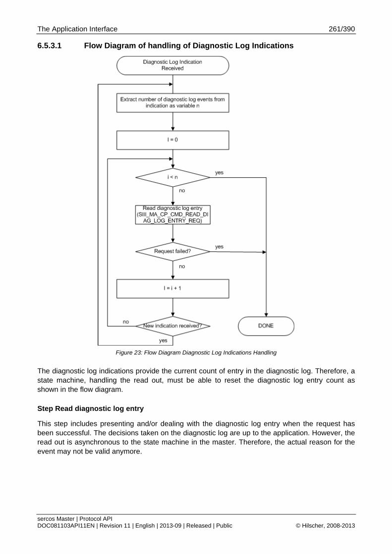
The Application Interface 261/390
sercos Master | Protocol API DOC081103API11EN | Revision 11 | English | 2013-09 | Released | Public © Hilscher, 2008-2013
6.5.3.1 Flow Diagram of handling of Diagnostic Log Indications
Figure 23: Flow Diagram Diagnostic Log Indications Handling
The diagnostic log indications provide the current count of entry in the diagnostic log. Therefore, a state machine, handling the read out, must be able to reset the diagnostic log entry count as shown in the flow diagram.
Step Read diagnostic log entry
This step includes presenting and/or dealing with the diagnostic log entry when the request has been successful. The decisions taken on the diagnostic log are up to the application. However, the read out is asynchronous to the state machine in the master. Therefore, the actual reason for the event may not be valid anymore.
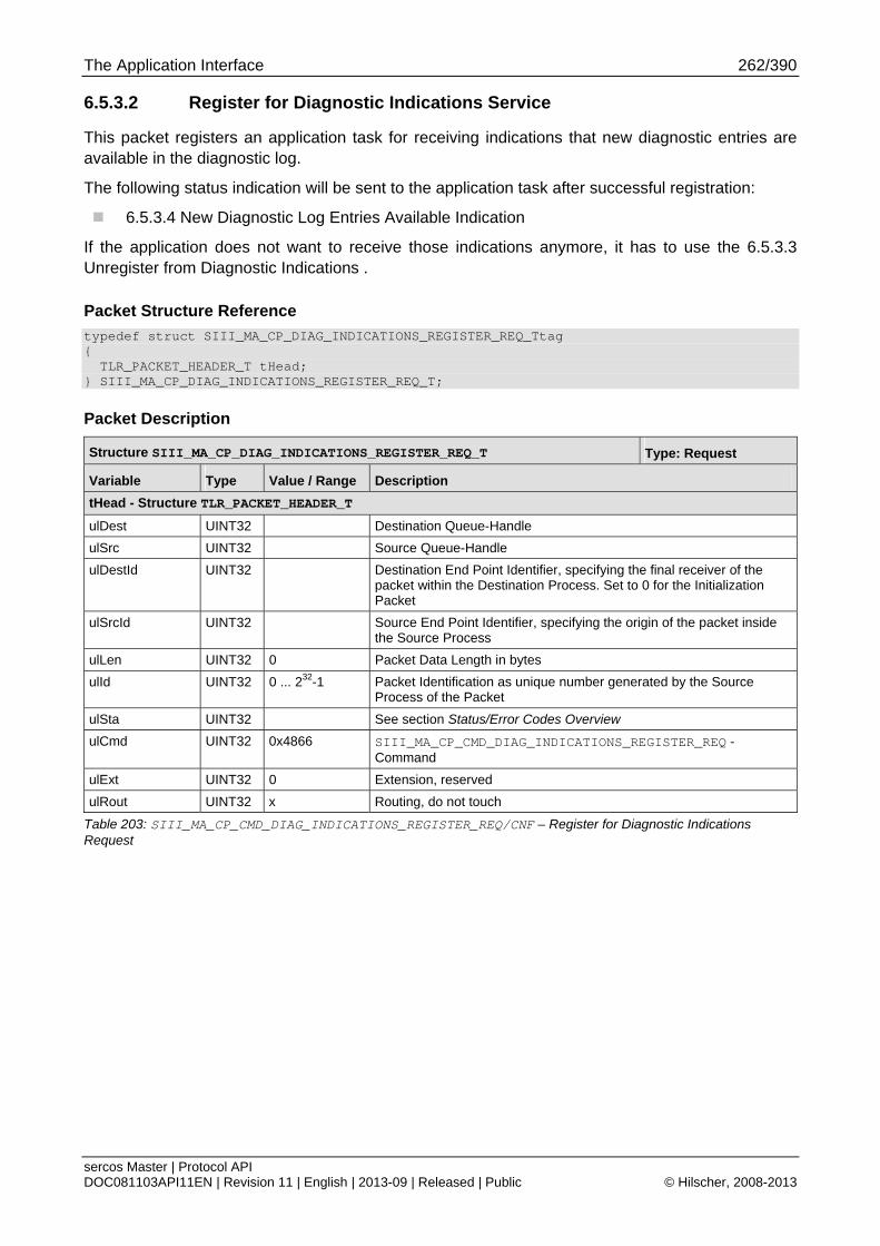
The Application Interface 262/390
sercos Master | Protocol API DOC081103API11EN | Revision 11 | English | 2013-09 | Released | Public © Hilscher, 2008-2013
6.5.3.2 Register for Diagnostic Indications Service
This packet registers an application task for receiving indications that new diagnostic entries are available in the diagnostic log.
The following status indication will be sent to the application task after successful registration:
6.5.3.4 New Diagnostic Log Entries Available Indication
If the application does not want to receive those indications anymore, it has to use the 6.5.3.3 Unregister from Diagnostic Indications .
Packet Structure Reference
typedef struct SIII_MA_CP_DIAG_INDICATIONS_REGISTER_REQ_Ttag { TLR_PACKET_HEADER_T tHead; } SIII_MA_CP_DIAG_INDICATIONS_REGISTER_REQ_T;
Packet Description
Structure SIII_MA_CP_DIAG_INDICATIONS_REGISTER_REQ_T Type: Request
Variable Type Value / Range Description
tHead - Structure TLR_PACKET_HEADER_T
ulDest UINT32 Destination Queue-Handle
ulSrc UINT32 Source Queue-Handle
ulDestId UINT32 Destination End Point Identifier, specifying the final receiver of the packet within the Destination Process. Set to 0 for the Initialization Packet
ulSrcId UINT32 Source End Point Identifier, specifying the origin of the packet inside the Source Process
ulLen UINT32 0 Packet Data Length in bytes
ulId UINT32 0 ... 232-1 Packet Identification as unique number generated by the Source Process of the Packet
ulSta UINT32 See section Status/Error Codes Overview
ulCmd UINT32 0x4866 SIII_MA_CP_CMD_DIAG_INDICATIONS_REGISTER_REQ - Command
ulExt UINT32 0 Extension, reserved
ulRout UINT32 x Routing, do not touch
Table 203: SIII_MA_CP_CMD_DIAG_INDICATIONS_REGISTER_REQ/CNF – Register for Diagnostic Indications Request
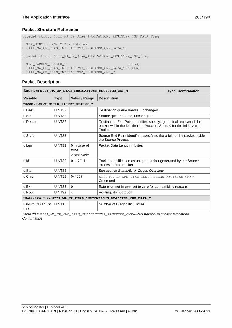
The Application Interface 263/390
sercos Master | Protocol API DOC081103API11EN | Revision 11 | English | 2013-09 | Released | Public © Hilscher, 2008-2013
Packet Structure Reference
typedef struct SIII_MA_CP_DIAG_INDICATIONS_REGISTER_CNF_DATA_Ttag { TLR_UINT16 usNumOfDiagEntries; } SIII_MA_CP_DIAG_INDICATIONS_REGISTER_CNF_DATA_T; typedef struct SIII_MA_CP_DIAG_INDICATIONS_REGISTER_CNF_Ttag { TLR_PACKET_HEADER_T tHead; SIII_MA_CP_DIAG_INDICATIONS_REGISTER_CNF_DATA_T tData; } SIII_MA_CP_DIAG_INDICATIONS_REGISTER_CNF_T;
Packet Description
Structure SIII_MA_CP_DIAG_INDICATIONS_REGISTER_CNF_T Type: Confirmation
Variable Type Value / Range Description
tHead - Structure TLR_PACKET_HEADER_T
ulDest UINT32 Destination queue handle, unchanged
ulSrc UINT32 Source queue handle, unchanged
ulDestId UINT32 Destination End Point Identifier, specifying the final receiver of the packet within the Destination Process. Set to 0 for the Initialization Packet
ulSrcId UINT32 Source End Point Identifier, specifying the origin of the packet inside the Source Process
ulLen UINT32 0 in case of error
2 otherwise
Packet Data Length in bytes
ulId UINT32 0 ... 232-1 Packet Identification as unique number generated by the Source Process of the Packet
ulSta UINT32 See section Status/Error Codes Overview
ulCmd UINT32 0x4867 SIII_MA_CP_CMD_DIAG_INDICATIONS_REGISTER_CNF - Command
ulExt UINT32 0 Extension not in use, set to zero for compatibility reasons
ulRout UINT32 x Routing, do not touch
tData - Structure SIII_MA_CP_DIAG_INDICATIONS_REGISTER_CNF_DATA_T
usNumOfDiagEntries
UINT16 Number of Diagnostic Entries
Table 204: SIII_MA_CP_CMD_DIAG_INDICATIONS_REGISTER_CNF – Register for Diagnostic Indications Confirmation

The Application Interface 264/390
sercos Master | Protocol API DOC081103API11EN | Revision 11 | English | 2013-09 | Released | Public © Hilscher, 2008-2013
6.5.3.3 Unregister from Diagnostic Indications Service
This packet deregisters an application task from receiving diagnostic indications.
The following diagnostic indications will not be sent anymore to the application after successful deregistration:
6.5.3.4 New Diagnostic Log Entries Available Indication
Packet Structure Reference
typedef struct SIII_MA_CP_DIAG_INDICATIONS_UNREGISTER_REQ_Ttag { TLR_PACKET_HEADER_T tHead; } SIII_MA_CP_DIAG_INDICATIONS_UNREGISTER_REQ_T;
Packet Description
Structure SIII_MA_CP_DIAG_INDICATIONS_UNREGISTER_REQ_T Type: Request
Variable Type Value / Range Description
tHead - Structure TLR_PACKET_HEADER_T
ulDest UINT32 Destination Queue-Handle
ulSrc UINT32 Source Queue-Handle
ulDestId UINT32 Destination End Point Identifier, specifying the final receiver of the packet within the Destination Process. Set to 0 for the Initialization Packet
ulSrcId UINT32 Source End Point Identifier, specifying the origin of the packet inside the Source Process
ulLen UINT32 0 Packet Data Length in bytes
ulId UINT32 0 ... 232-1 Packet Identification as unique number generated by the Source Process of the Packet
ulSta UINT32 See section Status/Error Codes Overview
ulCmd UINT32 0x4868 SIII_MA_CP_CMD_DIAG_INDICATIONS_UNREGISTER_REQ - Command
ulExt UINT32 0 Extension, reserved
ulRout UINT32 x Routing, do not touch
Table 205: SIII_MA_CP_CMD_DIAG_INDICATIONS_UNREGISTER_REQ/CNF – Unregister from Diagnostic Indications Request
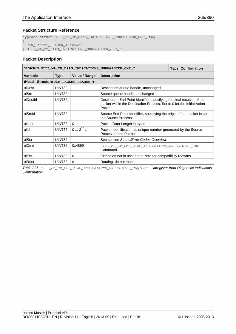
The Application Interface 265/390
sercos Master | Protocol API DOC081103API11EN | Revision 11 | English | 2013-09 | Released | Public © Hilscher, 2008-2013
Packet Structure Reference
typedef struct SIII_MA_CP_DIAG_INDICATIONS_UNREGISTER_CNF_Ttag { TLR_PACKET_HEADER_T tHead; } SIII_MA_CP_DIAG_INDICATIONS_UNREGISTER_CNF_T;
Packet Description
Structure SIII_MA_CP_DIAG_INDICATIONS_UNREGISTER_CNF_T Type: Confirmation
Variable Type Value / Range Description
tHead - Structure TLR_PACKET_HEADER_T
ulDest UINT32 Destination queue handle, unchanged
ulSrc UINT32 Source queue handle, unchanged
ulDestId UINT32 Destination End Point Identifier, specifying the final receiver of the packet within the Destination Process. Set to 0 for the Initialization Packet
ulSrcId UINT32 Source End Point Identifier, specifying the origin of the packet inside the Source Process
ulLen UINT32 0 Packet Data Length in bytes
ulId UINT32 0 ... 232-1 Packet Identification as unique number generated by the Source Process of the Packet
ulSta UINT32 See section Status/Error Codes Overview
ulCmd UINT32 0x4869 SIII_MA_CP_CMD_DIAG_INDICATIONS_UNREGISTER_CNF - Command
ulExt UINT32 0 Extension not in use, set to zero for compatibility reasons
ulRout UINT32 x Routing, do not touch
Table 206: SIII_MA_CP_CMD_DIAG_INDICATIONS_UNREGISTER_REQ/CNF – Unregister from Diagnostic Indications Confirmation
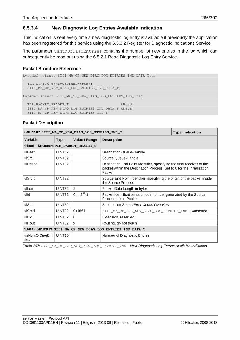
The Application Interface 266/390
sercos Master | Protocol API DOC081103API11EN | Revision 11 | English | 2013-09 | Released | Public © Hilscher, 2008-2013
6.5.3.4 New Diagnostic Log Entries Available Indication
This indication is sent every time a new diagnostic log entry is available if previously the application has been registered for this service using the 6.5.3.2 Register for Diagnostic Indications Service.
The parameter usNumOfDiagEntries contains the number of new entries in the log which can subsequently be read out using the 6.5.2.1 Read Diagnostic Log Entry Service.
Packet Structure Reference
typedef _struct SIII_MA_CP_NEW_DIAG_LOG_ENTRIES_IND_DATA_Ttag { TLR_UINT16 usNumOfDiagEntries; } SIII_MA_CP_NEW_DIAG_LOG_ENTRIES_IND_DATA_T; typedef struct SIII_MA_CP_NEW_DIAG_LOG_ENTRIES_IND_Ttag { TLR_PACKET_HEADER_T tHead; SIII_MA_CP_NEW_DIAG_LOG_ENTRIES_IND_DATA_T tData; } SIII_MA_CP_NEW_DIAG_LOG_ENTRIES_IND_T;
Packet Description
Structure SIII_MA_CP_NEW_DIAG_LOG_ENTRIES_IND_T Type: Indication
Variable Type Value / Range Description
tHead - Structure TLR_PACKET_HEADER_T
ulDest UINT32 Destination Queue-Handle
ulSrc UINT32 Source Queue-Handle
ulDestId UINT32 Destination End Point Identifier, specifying the final receiver of the packet within the Destination Process. Set to 0 for the Initialization Packet
ulSrcId UINT32 Source End Point Identifier, specifying the origin of the packet inside the Source Process
ulLen UINT32 2 Packet Data Length in bytes
ulId UINT32 0 ... 232-1 Packet Identification as unique number generated by the Source Process of the Packet
ulSta UINT32 See section Status/Error Codes Overview
ulCmd UINT32 0x4864 SIII_MA_CP_CMD_NEW_DIAG_LOG_ENTRIES_IND - Command
ulExt UINT32 0 Extension, reserved
ulRout UINT32 x Routing, do not touch
tData - Structure SIII_MA_CP_NEW_DIAG_LOG_ENTRIES_IND_DATA_T
usNumOfDiagEntries
UINT16 Number of Diagnostic Entries
Table 207: SIII_MA_CP_CMD_NEW_DIAG_LOG_ENTRIES_IND – New Diagnostic Log Entries Available Indication
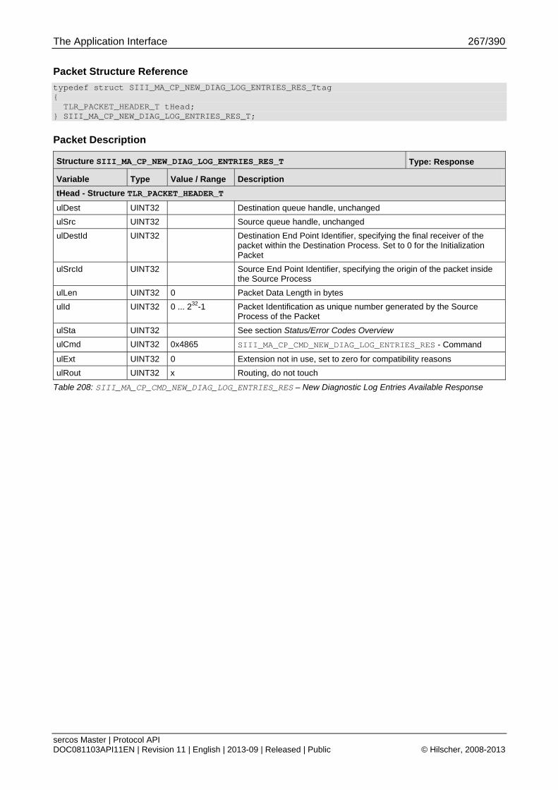
The Application Interface 267/390
sercos Master | Protocol API DOC081103API11EN | Revision 11 | English | 2013-09 | Released | Public © Hilscher, 2008-2013
Packet Structure Reference
typedef struct SIII_MA_CP_NEW_DIAG_LOG_ENTRIES_RES_Ttag { TLR_PACKET_HEADER_T tHead; } SIII_MA_CP_NEW_DIAG_LOG_ENTRIES_RES_T;
Packet Description
Structure SIII_MA_CP_NEW_DIAG_LOG_ENTRIES_RES_T Type: Response
Variable Type Value / Range Description
tHead - Structure TLR_PACKET_HEADER_T
ulDest UINT32 Destination queue handle, unchanged
ulSrc UINT32 Source queue handle, unchanged
ulDestId UINT32 Destination End Point Identifier, specifying the final receiver of the packet within the Destination Process. Set to 0 for the Initialization Packet
ulSrcId UINT32 Source End Point Identifier, specifying the origin of the packet inside the Source Process
ulLen UINT32 0 Packet Data Length in bytes
ulId UINT32 0 ... 232-1 Packet Identification as unique number generated by the Source Process of the Packet
ulSta UINT32 See section Status/Error Codes Overview
ulCmd UINT32 0x4865 SIII_MA_CP_CMD_NEW_DIAG_LOG_ENTRIES_RES - Command
ulExt UINT32 0 Extension not in use, set to zero for compatibility reasons
ulRout UINT32 x Routing, do not touch
Table 208: SIII_MA_CP_CMD_NEW_DIAG_LOG_ENTRIES_RES – New Diagnostic Log Entries Available Response
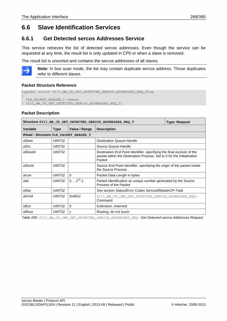
The Application Interface 268/390
sercos Master | Protocol API DOC081103API11EN | Revision 11 | English | 2013-09 | Released | Public © Hilscher, 2008-2013
6.6 Slave Identification Services
6.6.1 Get Detected sercos Addresses Service
This service retrieves the list of detected sercos addresses. Even though the service can be requested at any time, the result list is only updated in CP0 or when a slave is removed.
The result list is unsorted and contains the sercos addresses of all slaves.
Note: In bus scan mode, the list may contain duplicate sercos address. Those duplicates refer to different slaves.
Packet Structure Reference
typedef struct SIII_MA_CP_GET_DETECTED_SERCOS_ADDRESSES_REQ_Ttag { TLR_PACKET_HEADER_T tHead; } SIII_MA_CP_GET_DETECTED_SERCOS_ADDRESSES_REQ_T;
Packet Description
Structure SIII_MA_CP_GET_DETECTED_SERCOS_ADDRESSES_REQ_T Type: Request
Variable Type Value / Range Description
tHead - Structure TLR_PACKET_HEADER_T
ulDest UINT32 Destination Queue-Handle
ulSrc UINT32 Source Queue-Handle
ulDestId UINT32 Destination End Point Identifier, specifying the final receiver of the packet within the Destination Process. Set to 0 for the Initialization Packet
ulSrcId UINT32 Source End Point Identifier, specifying the origin of the packet inside the Source Process
ulLen UINT32 0 Packet Data Length in bytes
ulId UINT32 0 ... 232-1 Packet Identification as unique number generated by the Source Process of the Packet
ulSta UINT32 See section Status/Error Codes SercosIIIMasterCP-Task
ulCmd UINT32 0x4812 SIII_MA_CP_CMD_GET_DETECTED_SERCOS_ADDRESSES_REQ - Command
ulExt UINT32 0 Extension, reserved
ulRout UINT32 x Routing, do not touch
Table 209: SIII_MA_CP_CMD_GET_DETECTED_SERCOS_ADDRESSES_REQ - Get Detected sercos Addresses Request
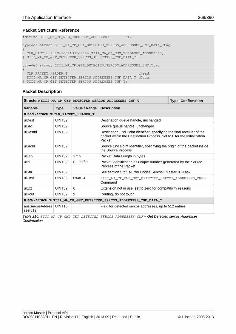
The Application Interface 269/390
sercos Master | Protocol API DOC081103API11EN | Revision 11 | English | 2013-09 | Released | Public © Hilscher, 2008-2013
Packet Structure Reference
#define SIII_MA_CP_NUM_TOPOLOGY_ADDRESSES 512 typedef struct SIII_MA_CP_GET_DETECTED_SERCOS_ADDRESSES_CNF_DATA_Ttag { TLR_UINT16 ausSercosAddresses[SIII_MA_CP_NUM_TOPOLOGY_ADDRESSES]; } SIII_MA_CP_GET_DETECTED_SERCOS_ADDRESSES_CNF_DATA_T; typedef struct SIII_MA_CP_GET_DETECTED_SERCOS_ADDRESSES_CNF_Ttag { TLR_PACKET_HEADER_T tHead; SIII_MA_CP_GET_DETECTED_SERCOS_ADDRESSES_CNF_DATA_T tData; } SIII_MA_CP_GET_DETECTED_SERCOS_ADDRESSES_CNF_T;
Packet Description
Structure SIII_MA_CP_GET_DETECTED_SERCOS_ADDRESSES_CNF_T Type: Confirmation
Variable Type Value / Range Description
tHead - Structure TLR_PACKET_HEADER_T
ulDest UINT32 Destination queue handle, unchanged
ulSrc UINT32 Source queue handle, unchanged
ulDestId UINT32 Destination End Point Identifier, specifying the final receiver of the packet within the Destination Process. Set to 0 for the Initialization Packet
ulSrcId UINT32 Source End Point Identifier, specifying the origin of the packet inside the Source Process
ulLen UINT32 2 * n Packet Data Length in bytes
ulId UINT32 0 ... 232-1 Packet Identification as unique number generated by the Source Process of the Packet
ulSta UINT32 See section Status/Error Codes SercosIIIMasterCP-Task
ulCmd UINT32 0x4813 SIII_MA_CP_CMD_GET_DETECTED_SERCOS_ADDRESSES_CNF - Command
ulExt UINT32 0 Extension not in use, set to zero for compatibility reasons
ulRout UINT32 x Routing, do not touch
tData - Structure SIII_MA_CP_GET_DETECTED_SERCOS_ADDRESSES_CNF_DATA_T
ausSercosAddresses[512]
UINT16[] Field for detected sercos addresses, up to 512 entries
Table 210: SIII_MA_CP_CMD_GET_DETECTED_SERCOS_ADDRESSES_CNF – Get Detected sercos Addresses Confirmation
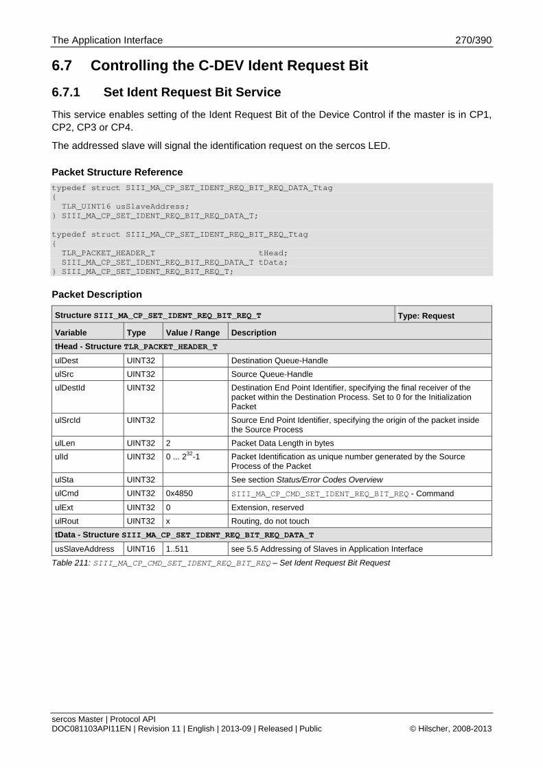
The Application Interface 270/390
sercos Master | Protocol API DOC081103API11EN | Revision 11 | English | 2013-09 | Released | Public © Hilscher, 2008-2013
6.7 Controlling the C-DEV Ident Request Bit
6.7.1 Set Ident Request Bit Service
This service enables setting of the Ident Request Bit of the Device Control if the master is in CP1, CP2, CP3 or CP4.
The addressed slave will signal the identification request on the sercos LED.
Packet Structure Reference
typedef struct SIII_MA_CP_SET_IDENT_REQ_BIT_REQ_DATA_Ttag { TLR_UINT16 usSlaveAddress; } SIII_MA_CP_SET_IDENT_REQ_BIT_REQ_DATA_T; typedef struct SIII_MA_CP_SET_IDENT_REQ_BIT_REQ_Ttag { TLR_PACKET_HEADER_T tHead; SIII_MA_CP_SET_IDENT_REQ_BIT_REQ_DATA_T tData; } SIII_MA_CP_SET_IDENT_REQ_BIT_REQ_T;
Packet Description
Structure SIII_MA_CP_SET_IDENT_REQ_BIT_REQ_T Type: Request
Variable Type Value / Range Description
tHead - Structure TLR_PACKET_HEADER_T
ulDest UINT32 Destination Queue-Handle
ulSrc UINT32 Source Queue-Handle
ulDestId UINT32 Destination End Point Identifier, specifying the final receiver of the packet within the Destination Process. Set to 0 for the Initialization Packet
ulSrcId UINT32 Source End Point Identifier, specifying the origin of the packet inside the Source Process
ulLen UINT32 2 Packet Data Length in bytes
ulId UINT32 0 ... 232-1 Packet Identification as unique number generated by the Source Process of the Packet
ulSta UINT32 See section Status/Error Codes Overview
ulCmd UINT32 0x4850 SIII_MA_CP_CMD_SET_IDENT_REQ_BIT_REQ - Command
ulExt UINT32 0 Extension, reserved
ulRout UINT32 x Routing, do not touch
tData - Structure SIII_MA_CP_SET_IDENT_REQ_BIT_REQ_DATA_T
usSlaveAddress UINT16 1..511 see 5.5 Addressing of Slaves in Application Interface
Table 211: SIII_MA_CP_CMD_SET_IDENT_REQ_BIT_REQ – Set Ident Request Bit Request

The Application Interface 271/390
sercos Master | Protocol API DOC081103API11EN | Revision 11 | English | 2013-09 | Released | Public © Hilscher, 2008-2013
Packet Structure Reference
typedef struct SIII_MA_CP_SET_IDENT_REQ_BIT_CNF_Ttag { TLR_PACKET_HEADER_T tHead; } SIII_MA_CP_SET_IDENT_REQ_BIT_CNF_T;
Packet Description
Structure SIII_MA_CP_SET_IDENT_REQ_BIT_CNF_T Type: Confirmation
Variable Type Value / Range Description
tHead - Structure TLR_PACKET_HEADER_T
ulDest UINT32 Destination queue handle, unchanged
ulSrc UINT32 Source queue handle, unchanged
ulDestId UINT32 Destination End Point Identifier, specifying the final receiver of the packet within the Destination Process. Set to 0 for the Initialization Packet
ulSrcId UINT32 Source End Point Identifier, specifying the origin of the packet inside the Source Process
ulLen UINT32 0 Packet Data Length in bytes
ulId UINT32 0 ... 232-1 Packet Identification as unique number generated by the Source Process of the Packet
ulSta UINT32 See section Status/Error Codes Overview
ulCmd UINT32 0x4851 SIII_MA_CP_CMD_SET_IDENT_REQ_BIT_CNF - Command
ulExt UINT32 0 Extension not in use, set to zero for compatibility reasons
ulRout UINT32 x Routing, do not touch
Table 212: SIII_MA_CP_CMD_SET_IDENT_REQ_BIT_CNF – Set Ident Request Bit Confirmation
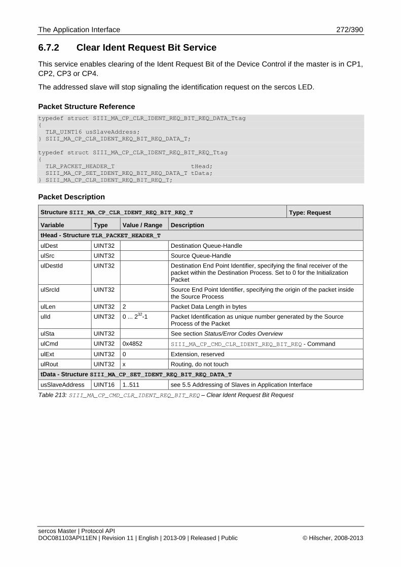
The Application Interface 272/390
sercos Master | Protocol API DOC081103API11EN | Revision 11 | English | 2013-09 | Released | Public © Hilscher, 2008-2013
6.7.2 Clear Ident Request Bit Service
This service enables clearing of the Ident Request Bit of the Device Control if the master is in CP1, CP2, CP3 or CP4.
The addressed slave will stop signaling the identification request on the sercos LED.
Packet Structure Reference
typedef struct SIII_MA_CP_CLR_IDENT_REQ_BIT_REQ_DATA_Ttag { TLR_UINT16 usSlaveAddress; } SIII_MA_CP_CLR_IDENT_REQ_BIT_REQ_DATA_T; typedef struct SIII_MA_CP_CLR_IDENT_REQ_BIT_REQ_Ttag { TLR_PACKET_HEADER_T tHead; SIII_MA_CP_SET_IDENT_REQ_BIT_REQ_DATA_T tData; } SIII_MA_CP_CLR_IDENT_REQ_BIT_REQ_T;
Packet Description
Structure SIII_MA_CP_CLR_IDENT_REQ_BIT_REQ_T Type: Request
Variable Type Value / Range Description
tHead - Structure TLR_PACKET_HEADER_T
ulDest UINT32 Destination Queue-Handle
ulSrc UINT32 Source Queue-Handle
ulDestId UINT32 Destination End Point Identifier, specifying the final receiver of the packet within the Destination Process. Set to 0 for the Initialization Packet
ulSrcId UINT32 Source End Point Identifier, specifying the origin of the packet inside the Source Process
ulLen UINT32 2 Packet Data Length in bytes
ulId UINT32 0 ... 232-1 Packet Identification as unique number generated by the Source Process of the Packet
ulSta UINT32 See section Status/Error Codes Overview
ulCmd UINT32 0x4852 SIII_MA_CP_CMD_CLR_IDENT_REQ_BIT_REQ - Command
ulExt UINT32 0 Extension, reserved
ulRout UINT32 x Routing, do not touch
tData - Structure SIII_MA_CP_SET_IDENT_REQ_BIT_REQ_DATA_T
usSlaveAddress UINT16 1..511 see 5.5 Addressing of Slaves in Application Interface
Table 213: SIII_MA_CP_CMD_CLR_IDENT_REQ_BIT_REQ – Clear Ident Request Bit Request

The Application Interface 273/390
sercos Master | Protocol API DOC081103API11EN | Revision 11 | English | 2013-09 | Released | Public © Hilscher, 2008-2013
Packet Structure Reference
typedef struct SIII_MA_CP_CLR_IDENT_REQ_BIT_CNF_Ttag { TLR_PACKET_HEADER_T tHead; } SIII_MA_CP_CLR_IDENT_REQ_BIT_CNF_T;
Packet Description
Structure SIII_MA_CP_CLR_IDENT_REQ_BIT_CNF_T Type: Confirmation
Variable Type Value / Range Description
tHead - Structure TLR_PACKET_HEADER_T
ulDest UINT32 Destination queue handle, unchanged
ulSrc UINT32 Source queue handle, unchanged
ulDestId UINT32 Destination End Point Identifier, specifying the final receiver of the packet within the Destination Process. Set to 0 for the Initialization Packet
ulSrcId UINT32 Source End Point Identifier, specifying the origin of the packet inside the Source Process
ulLen UINT32 0 Packet Data Length in bytes
ulId UINT32 0 ... 232-1 Packet Identification as unique number generated by the Source Process of the Packet
ulSta UINT32 See section Status/Error Codes Overview
ulCmd UINT32 0x4853 SIII_MA_CP_CMD_CLR_IDENT_REQ_BIT_CNF - Command
ulExt UINT32 0 Extension not in use, set to zero for compatibility reasons
ulRout UINT32 x Routing, do not touch
Table 214: SIII_MA_CP_CMD_CLR_IDENT_REQ_BIT_CNF – Clear Ident Request Bit Confirmation
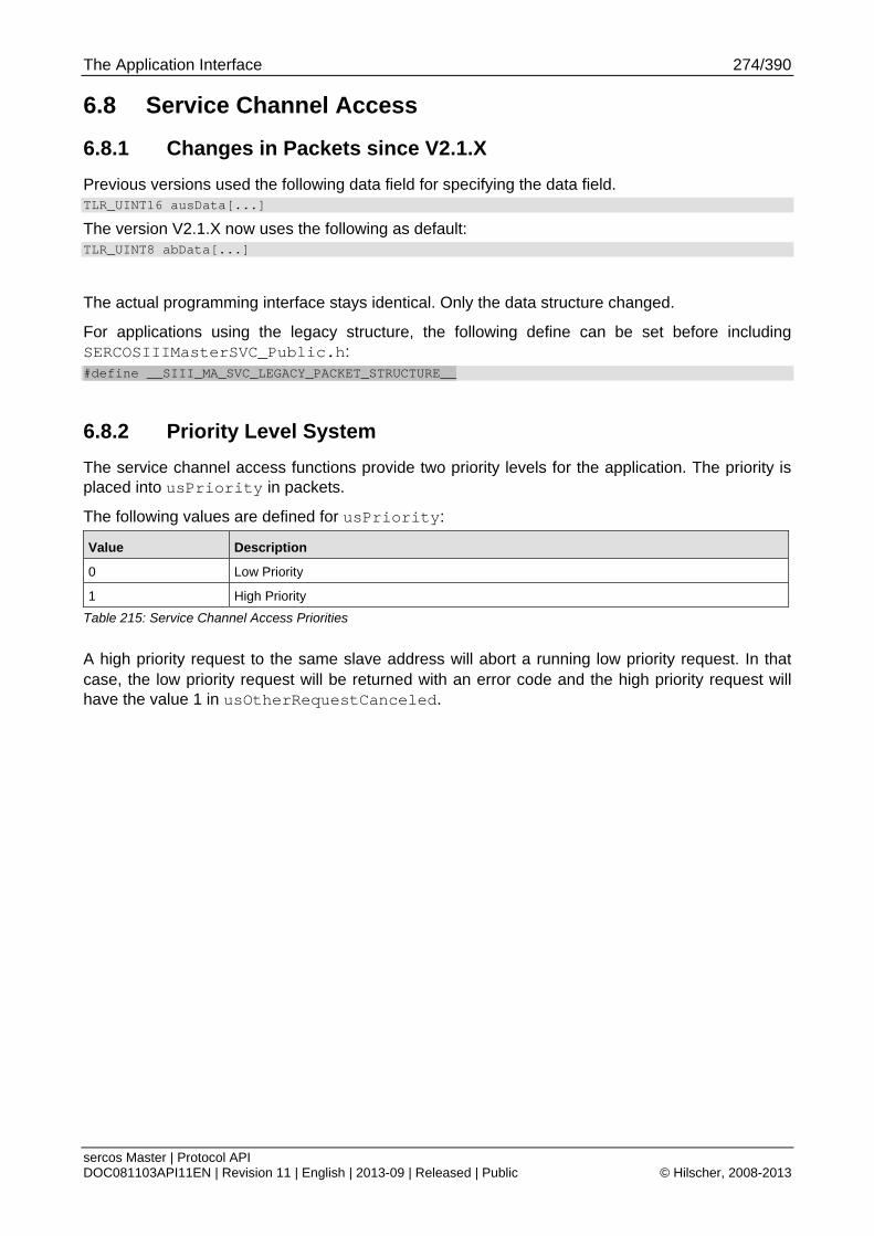
The Application Interface 274/390
sercos Master | Protocol API DOC081103API11EN | Revision 11 | English | 2013-09 | Released | Public © Hilscher, 2008-2013
6.8 Service Channel Access
6.8.1 Changes in Packets since V2.1.X
Previous versions used the following data field for specifying the data field. TLR_UINT16 ausData[...]
The version V2.1.X now uses the following as default: TLR_UINT8 abData[...]
The actual programming interface stays identical. Only the data structure changed.
For applications using the legacy structure, the following define can be set before including SERCOSIIIMasterSVC_Public.h: #define __SIII_MA_SVC_LEGACY_PACKET_STRUCTURE__
6.8.2 Priority Level System
The service channel access functions provide two priority levels for the application. The priority is placed into usPriority in packets.
The following values are defined for usPriority:
Value Description
0 Low Priority
1 High Priority
Table 215: Service Channel Access Priorities
A high priority request to the same slave address will abort a running low priority request. In that case, the low priority request will be returned with an error code and the high priority request will have the value 1 in usOtherRequestCanceled.
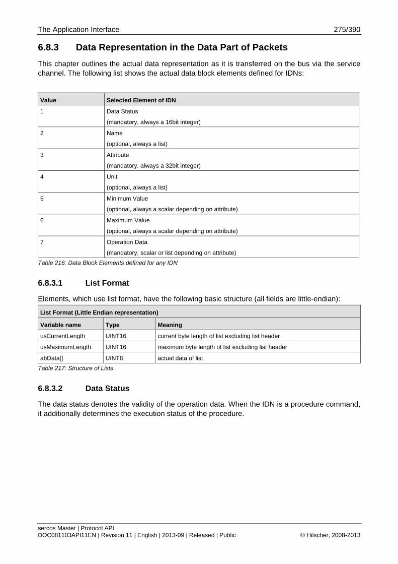
The Application Interface 275/390
sercos Master | Protocol API DOC081103API11EN | Revision 11 | English | 2013-09 | Released | Public © Hilscher, 2008-2013
6.8.3 Data Representation in the Data Part of Packets
This chapter outlines the actual data representation as it is transferred on the bus via the service channel. The following list shows the actual data block elements defined for IDNs:
Value Selected Element of IDN
1 Data Status
(mandatory, always a 16bit integer)
2 Name
(optional, always a list)
3 Attribute
(mandatory, always a 32bit integer)
4 Unit
(optional, always a list)
5 Minimum Value
(optional, always a scalar depending on attribute)
6 Maximum Value
(optional, always a scalar depending on attribute)
7 Operation Data
(mandatory, scalar or list depending on attribute)
Table 216: Data Block Elements defined for any IDN
6.8.3.1 List Format
Elements, which use list format, have the following basic structure (all fields are little-endian):
List Format (Little Endian representation)
Variable name Type Meaning
usCurrentLength UINT16 current byte length of list excluding list header
usMaximumLength UINT16 maximum byte length of list excluding list header
abData[] UINT8 actual data of list
Table 217: Structure of Lists
6.8.3.2 Data Status
The data status denotes the validity of the operation data. When the IDN is a procedure command, it additionally determines the execution status of the procedure.
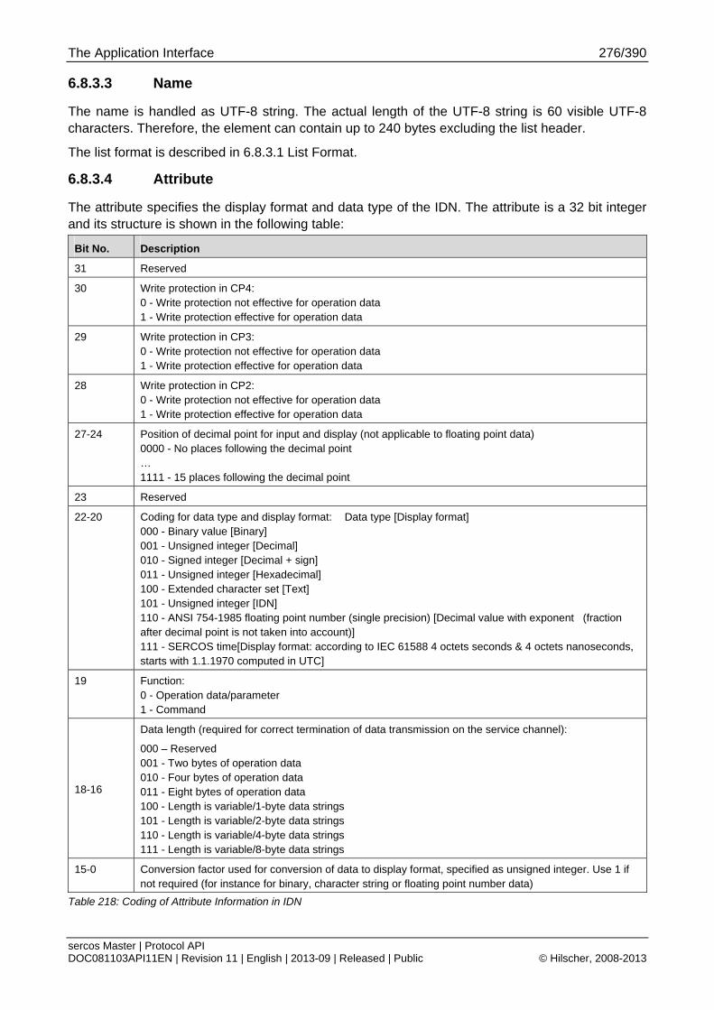
The Application Interface 276/390
sercos Master | Protocol API DOC081103API11EN | Revision 11 | English | 2013-09 | Released | Public © Hilscher, 2008-2013
6.8.3.3 Name
The name is handled as UTF-8 string. The actual length of the UTF-8 string is 60 visible UTF-8 characters. Therefore, the element can contain up to 240 bytes excluding the list header.
The list format is described in 6.8.3.1 List Format.
6.8.3.4 Attribute
The attribute specifies the display format and data type of the IDN. The attribute is a 32 bit integer and its structure is shown in the following table:
Bit No. Description
31 Reserved
30 Write protection in CP4: 0 - Write protection not effective for operation data 1 - Write protection effective for operation data
29 Write protection in CP3: 0 - Write protection not effective for operation data 1 - Write protection effective for operation data
28 Write protection in CP2: 0 - Write protection not effective for operation data 1 - Write protection effective for operation data
27-24 Position of decimal point for input and display (not applicable to floating point data) 0000 - No places following the decimal point … 1111 - 15 places following the decimal point
23 Reserved
22-20 Coding for data type and display format: Data type [Display format] 000 - Binary value [Binary] 001 - Unsigned integer [Decimal] 010 - Signed integer [Decimal + sign] 011 - Unsigned integer [Hexadecimal] 100 - Extended character set [Text] 101 - Unsigned integer [IDN] 110 - ANSI 754-1985 floating point number (single precision) [Decimal value with exponent (fraction after decimal point is not taken into account)] 111 - SERCOS time[Display format: according to IEC 61588 4 octets seconds & 4 octets nanoseconds, starts with 1.1.1970 computed in UTC]
19 Function: 0 - Operation data/parameter 1 - Command
18-16
Data length (required for correct termination of data transmission on the service channel):
000 – Reserved 001 - Two bytes of operation data 010 - Four bytes of operation data 011 - Eight bytes of operation data 100 - Length is variable/1-byte data strings 101 - Length is variable/2-byte data strings 110 - Length is variable/4-byte data strings 111 - Length is variable/8-byte data strings
15-0 Conversion factor used for conversion of data to display format, specified as unsigned integer. Use 1 if not required (for instance for binary, character string or floating point number data)
Table 218: Coding of Attribute Information in IDN
The Application Interface 277/390
sercos Master | Protocol API DOC081103API11EN | Revision 11 | English | 2013-09 | Released | Public © Hilscher, 2008-2013
6.8.3.5 Unit
The unit is handled as UTF-8 string. The actual length of the UTF-8 string is 12 visible UTF-8 characters. Therefore, the element can take up to 48 bytes excluding the list header.
The list format is described in 6.8.3.1 List Format.
6.8.3.6 Minimum Value
The minimum value presents the minimum value of the IDN. Depending on the data type, it may have a slightly different meaning. For details, see the sercos specification.
6.8.3.7 Maximum Value
The maximum value presents the minimum value of the IDN. Depending on the data type, it may have a slightly different meaning. For details, see the sercos specification.
6.8.3.8 Operation Data
The operation data is the actual parameter value that is stored at the IDN. Depending on the attribute, it is either a scalar or a list.
If the operation data is specified as list, the data representation within the service channel data includes the list header and must be counted when the total transfer byte length has to be specified. The list format is described in 6.8.3.1 List Format.
If the operation data is specified as scalar, the data representation within the service channel data only transfers the actual value (i.e. a 32 bit data type has 4 bytes transferred).
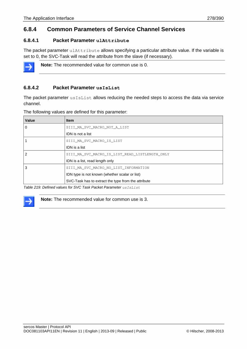
The Application Interface 278/390
sercos Master | Protocol API DOC081103API11EN | Revision 11 | English | 2013-09 | Released | Public © Hilscher, 2008-2013
6.8.4 Common Parameters of Service Channel Services
6.8.4.1 Packet Parameter ulAttribute
The packet parameter ulAttribute allows specifying a particular attribute value. If the variable is set to 0, the SVC-Task will read the attribute from the slave (if necessary).
Note: The recommended value for common use is 0.
6.8.4.2 Packet Parameter usIsList
The packet parameter usIsList allows reducing the needed steps to access the data via service channel.
The following values are defined for this parameter:
Value Item
0 SIII_MA_SVC_MACRO_NOT_A_LIST
IDN is not a list
1 SIII_MA_SVC_MACRO_IS_LIST
IDN is a list
2 SIII_MA_SVC_MACRO_IS_LIST_READ_LISTLENGTH_ONLY
IDN is a list, read length only
3 SIII_MA_SVC_MACRO_NO_LIST_INFORMATION
IDN type is not known (whether scalar or list)
SVC-Task has to extract the type from the attribute
Table 219: Defined values for SVC Task Packet Parameter usIsList
Note: The recommended value for common use is 3.
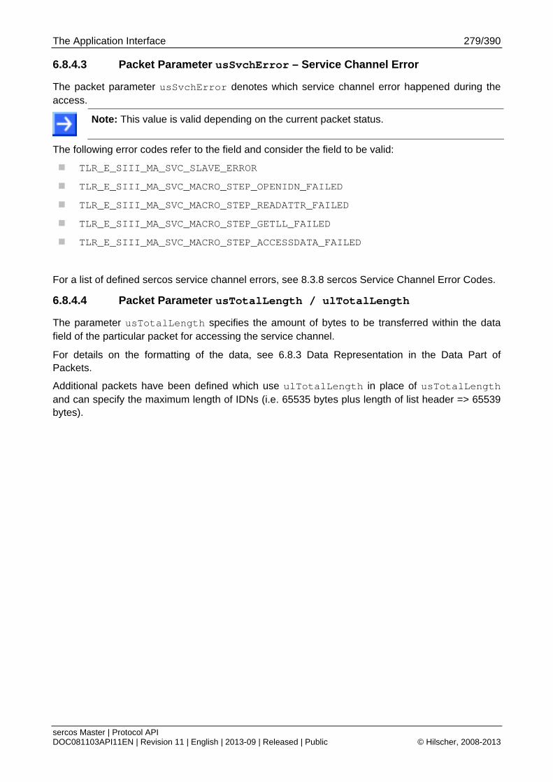
The Application Interface 279/390
sercos Master | Protocol API DOC081103API11EN | Revision 11 | English | 2013-09 | Released | Public © Hilscher, 2008-2013
6.8.4.3 Packet Parameter usSvchError – Service Channel Error
The packet parameter usSvchError denotes which service channel error happened during the access.
Note: This value is valid depending on the current packet status.
The following error codes refer to the field and consider the field to be valid:
TLR_E_SIII_MA_SVC_SLAVE_ERROR
TLR_E_SIII_MA_SVC_MACRO_STEP_OPENIDN_FAILED
TLR_E_SIII_MA_SVC_MACRO_STEP_READATTR_FAILED
TLR_E_SIII_MA_SVC_MACRO_STEP_GETLL_FAILED
TLR_E_SIII_MA_SVC_MACRO_STEP_ACCESSDATA_FAILED
For a list of defined sercos service channel errors, see 8.3.8 sercos Service Channel Error Codes.
6.8.4.4 Packet Parameter usTotalLength / ulTotalLength
The parameter usTotalLength specifies the amount of bytes to be transferred within the data field of the particular packet for accessing the service channel.
For details on the formatting of the data, see 6.8.3 Data Representation in the Data Part of Packets.
Additional packets have been defined which use ulTotalLength in place of usTotalLength and can specify the maximum length of IDNs (i.e. 65535 bytes plus length of list header => 65539 bytes).
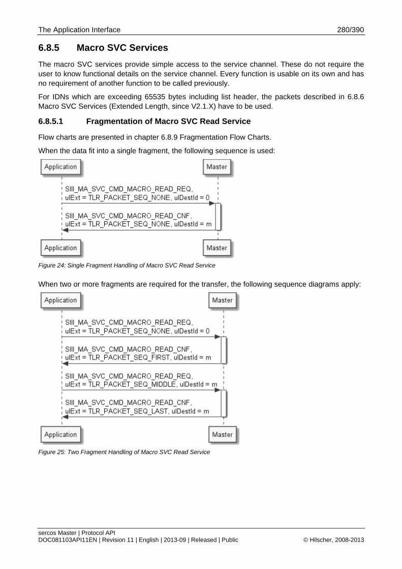
The Application Interface 280/390
sercos Master | Protocol API DOC081103API11EN | Revision 11 | English | 2013-09 | Released | Public © Hilscher, 2008-2013
6.8.5 Macro SVC Services
The macro SVC services provide simple access to the service channel. These do not require the user to know functional details on the service channel. Every function is usable on its own and has no requirement of another function to be called previously.
For IDNs which are exceeding 65535 bytes including list header, the packets described in 6.8.6 Macro SVC Services (Extended Length, since V2.1.X) have to be used.
6.8.5.1 Fragmentation of Macro SVC Read Service
Flow charts are presented in chapter 6.8.9 Fragmentation Flow Charts.
When the data fit into a single fragment, the following sequence is used:
Figure 24: Single Fragment Handling of Macro SVC Read Service
When two or more fragments are required for the transfer, the following sequence diagrams apply:
Figure 25: Two Fragment Handling of Macro SVC Read Service
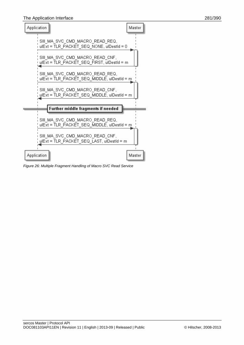
The Application Interface 281/390
sercos Master | Protocol API DOC081103API11EN | Revision 11 | English | 2013-09 | Released | Public © Hilscher, 2008-2013
Figure 26: Multiple Fragment Handling of Macro SVC Read Service
The Application Interface 282/390
sercos Master | Protocol API DOC081103API11EN | Revision 11 | English | 2013-09 | Released | Public © Hilscher, 2008-2013
6.8.5.2 Fragmentation of Macro SVC Write Service
Flow charts are presented in chapter 6.8.9 Fragmentation Flow Charts.
When the data fits into a single fragment, the following sequence is used:
Figure 27: Single Fragment Handling of Macro SVC Write Service
When two or more fragments are required for the transfer, the following sequence diagrams apply:
Figure 28: Two Fragment Handling of Macro SVC Write Service

The Application Interface 283/390
sercos Master | Protocol API DOC081103API11EN | Revision 11 | English | 2013-09 | Released | Public © Hilscher, 2008-2013
Figure 29: Multiple Fragment Handling of Macro SVC Write Service
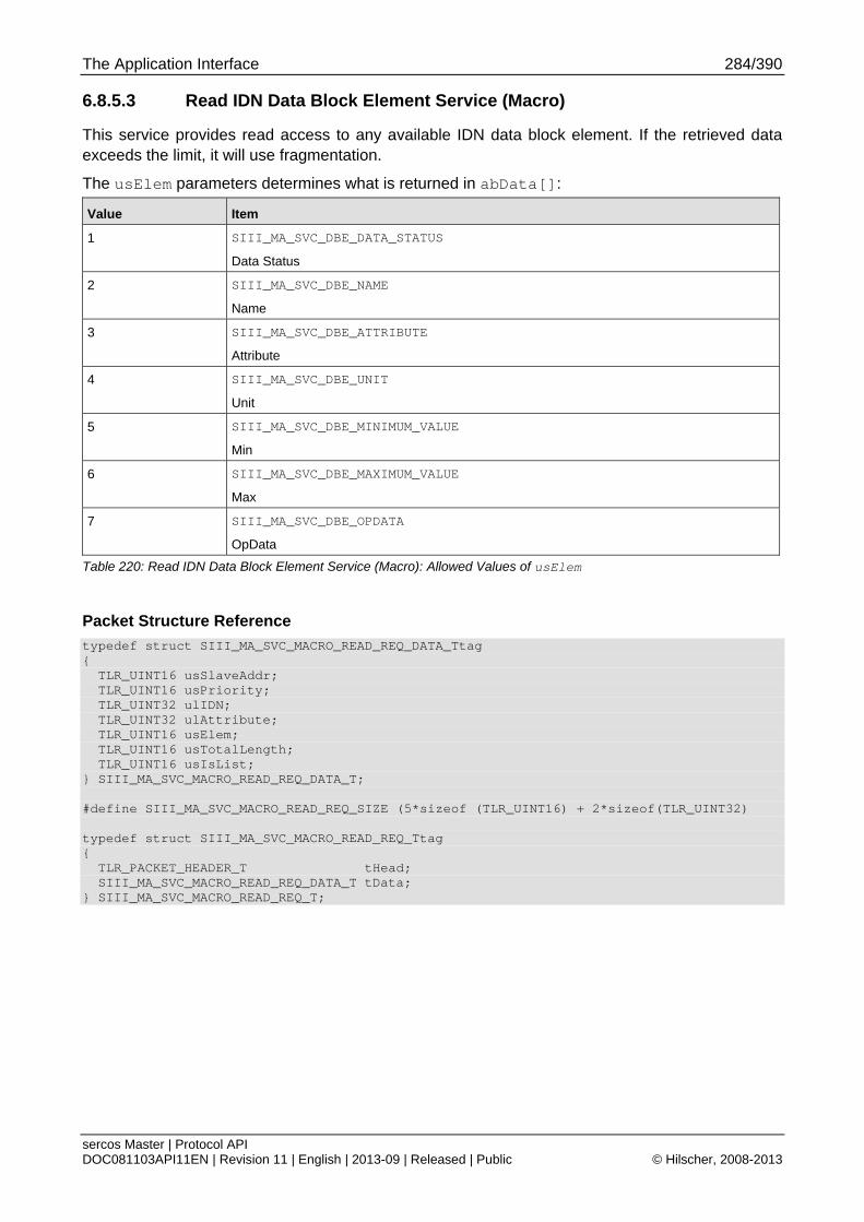
The Application Interface 284/390
sercos Master | Protocol API DOC081103API11EN | Revision 11 | English | 2013-09 | Released | Public © Hilscher, 2008-2013
6.8.5.3 Read IDN Data Block Element Service (Macro)
This service provides read access to any available IDN data block element. If the retrieved data exceeds the limit, it will use fragmentation.
The usElem parameters determines what is returned in abData[]:
Value Item
1 SIII_MA_SVC_DBE_DATA_STATUS
Data Status
2 SIII_MA_SVC_DBE_NAME
Name
3 SIII_MA_SVC_DBE_ATTRIBUTE
Attribute
4 SIII_MA_SVC_DBE_UNIT
Unit
5 SIII_MA_SVC_DBE_MINIMUM_VALUE
Min
6 SIII_MA_SVC_DBE_MAXIMUM_VALUE
Max
7 SIII_MA_SVC_DBE_OPDATA
OpData
Table 220: Read IDN Data Block Element Service (Macro): Allowed Values of usElem
Packet Structure Reference
typedef struct SIII_MA_SVC_MACRO_READ_REQ_DATA_Ttag { TLR_UINT16 usSlaveAddr; TLR_UINT16 usPriority; TLR_UINT32 ulIDN; TLR_UINT32 ulAttribute; TLR_UINT16 usElem; TLR_UINT16 usTotalLength; TLR_UINT16 usIsList; } SIII_MA_SVC_MACRO_READ_REQ_DATA_T; #define SIII_MA_SVC_MACRO_READ_REQ_SIZE (5*sizeof (TLR_UINT16) + 2*sizeof(TLR_UINT32) typedef struct SIII_MA_SVC_MACRO_READ_REQ_Ttag { TLR_PACKET_HEADER_T tHead; SIII_MA_SVC_MACRO_READ_REQ_DATA_T tData; } SIII_MA_SVC_MACRO_READ_REQ_T;
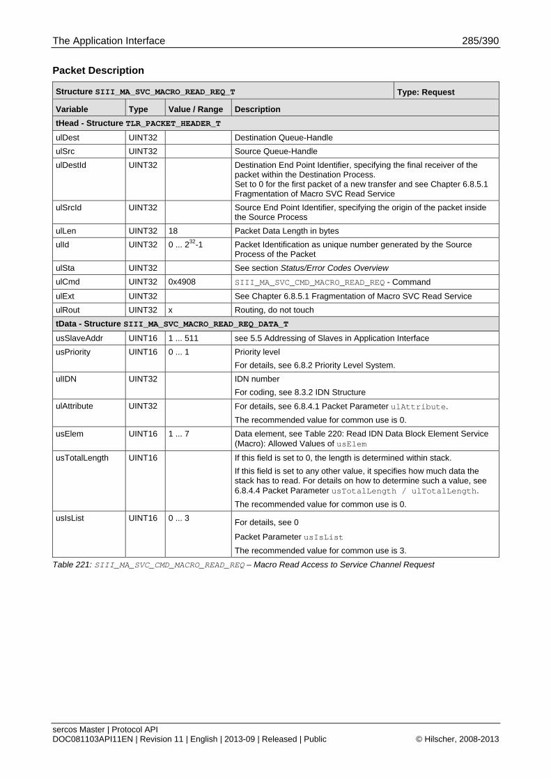
The Application Interface 285/390
sercos Master | Protocol API DOC081103API11EN | Revision 11 | English | 2013-09 | Released | Public © Hilscher, 2008-2013
Packet Description
Structure SIII_MA_SVC_MACRO_READ_REQ_T Type: Request
Variable Type Value / Range Description
tHead - Structure TLR_PACKET_HEADER_T
ulDest UINT32 Destination Queue-Handle
ulSrc UINT32 Source Queue-Handle
ulDestId UINT32 Destination End Point Identifier, specifying the final receiver of the packet within the Destination Process. Set to 0 for the first packet of a new transfer and see Chapter 6.8.5.1 Fragmentation of Macro SVC Read Service
ulSrcId UINT32 Source End Point Identifier, specifying the origin of the packet inside the Source Process
ulLen UINT32 18 Packet Data Length in bytes
ulId UINT32 0 ... 232-1 Packet Identification as unique number generated by the Source Process of the Packet
ulSta UINT32 See section Status/Error Codes Overview
ulCmd UINT32 0x4908 SIII_MA_SVC_CMD_MACRO_READ_REQ - Command
ulExt UINT32 See Chapter 6.8.5.1 Fragmentation of Macro SVC Read Service
ulRout UINT32 x Routing, do not touch
tData - Structure SIII_MA_SVC_MACRO_READ_REQ_DATA_T
usSlaveAddr UINT16 1 ... 511 see 5.5 Addressing of Slaves in Application Interface
usPriority UINT16 0 ... 1 Priority level
For details, see 6.8.2 Priority Level System.
ulIDN UINT32 IDN number
For coding, see 8.3.2 IDN Structure
ulAttribute UINT32 For details, see 6.8.4.1 Packet Parameter ulAttribute.
The recommended value for common use is 0.
usElem UINT16 1 ... 7 Data element, see Table 220: Read IDN Data Block Element Service (Macro): Allowed Values of usElem
usTotalLength UINT16 If this field is set to 0, the length is determined within stack.
If this field is set to any other value, it specifies how much data the stack has to read. For details on how to determine such a value, see 6.8.4.4 Packet Parameter usTotalLength / ulTotalLength.
The recommended value for common use is 0.
usIsList UINT16 0 ... 3 For details, see 0
Packet Parameter usIsList
The recommended value for common use is 3.
Table 221: SIII_MA_SVC_CMD_MACRO_READ_REQ – Macro Read Access to Service Channel Request
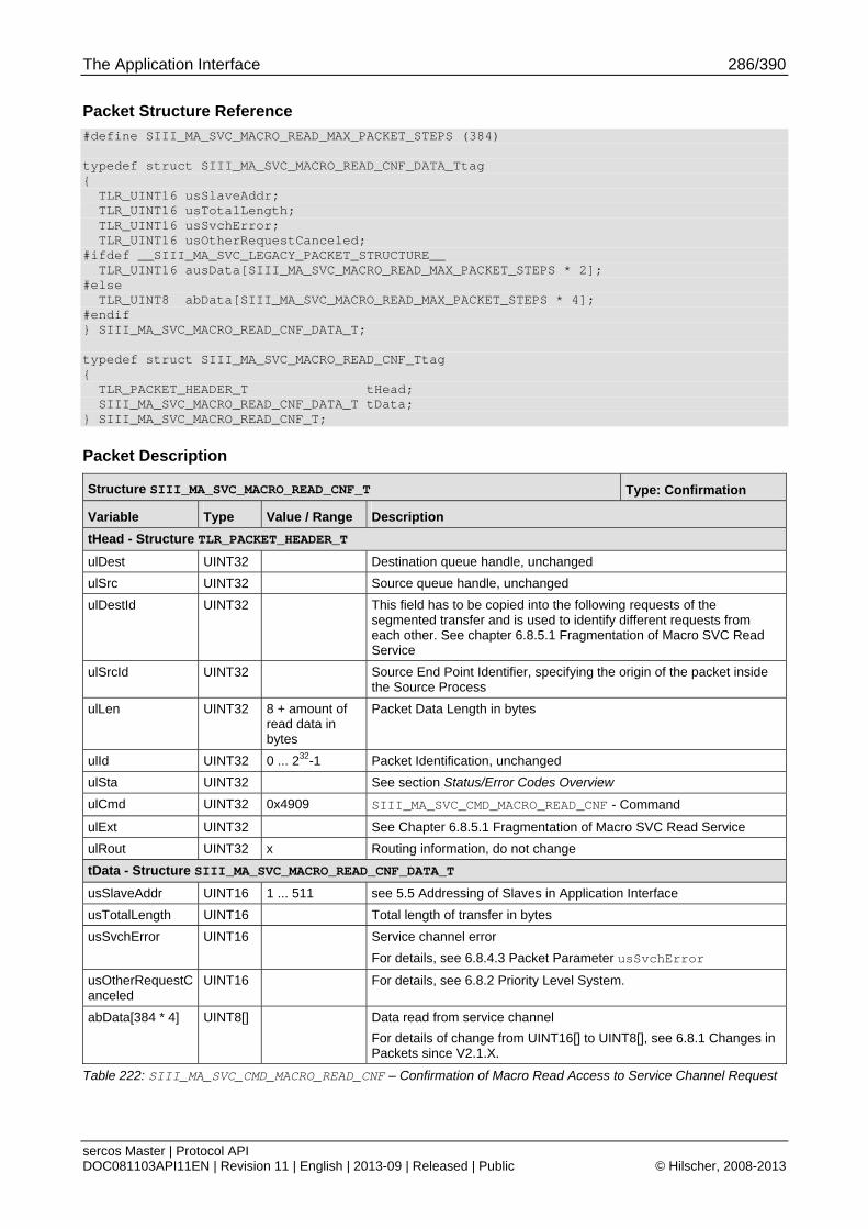
The Application Interface 286/390
sercos Master | Protocol API DOC081103API11EN | Revision 11 | English | 2013-09 | Released | Public © Hilscher, 2008-2013
Packet Structure Reference
#define SIII_MA_SVC_MACRO_READ_MAX_PACKET_STEPS (384) typedef struct SIII_MA_SVC_MACRO_READ_CNF_DATA_Ttag { TLR_UINT16 usSlaveAddr; TLR_UINT16 usTotalLength; TLR_UINT16 usSvchError; TLR_UINT16 usOtherRequestCanceled; #ifdef __SIII_MA_SVC_LEGACY_PACKET_STRUCTURE__ TLR_UINT16 ausData[SIII_MA_SVC_MACRO_READ_MAX_PACKET_STEPS * 2]; #else TLR_UINT8 abData[SIII_MA_SVC_MACRO_READ_MAX_PACKET_STEPS * 4]; #endif } SIII_MA_SVC_MACRO_READ_CNF_DATA_T; typedef struct SIII_MA_SVC_MACRO_READ_CNF_Ttag { TLR_PACKET_HEADER_T tHead; SIII_MA_SVC_MACRO_READ_CNF_DATA_T tData; } SIII_MA_SVC_MACRO_READ_CNF_T;
Packet Description
Structure SIII_MA_SVC_MACRO_READ_CNF_T Type: Confirmation
Variable Type Value / Range Description
tHead - Structure TLR_PACKET_HEADER_T
ulDest UINT32 Destination queue handle, unchanged
ulSrc UINT32 Source queue handle, unchanged
ulDestId UINT32 This field has to be copied into the following requests of the segmented transfer and is used to identify different requests from each other. See chapter 6.8.5.1 Fragmentation of Macro SVC Read Service
ulSrcId UINT32 Source End Point Identifier, specifying the origin of the packet inside the Source Process
ulLen UINT32 8 + amount of read data in bytes
Packet Data Length in bytes
ulId UINT32 0 ... 232-1 Packet Identification, unchanged
ulSta UINT32 See section Status/Error Codes Overview
ulCmd UINT32 0x4909 SIII_MA_SVC_CMD_MACRO_READ_CNF - Command
ulExt UINT32 See Chapter 6.8.5.1 Fragmentation of Macro SVC Read Service
ulRout UINT32 x Routing information, do not change
tData - Structure SIII_MA_SVC_MACRO_READ_CNF_DATA_T
usSlaveAddr UINT16 1 ... 511 see 5.5 Addressing of Slaves in Application Interface
usTotalLength UINT16 Total length of transfer in bytes
usSvchError UINT16 Service channel error
For details, see 6.8.4.3 Packet Parameter usSvchError
usOtherRequestCanceled
UINT16 For details, see 6.8.2 Priority Level System.
abData[384 * 4] UINT8[] Data read from service channel
For details of change from UINT16[] to UINT8[], see 6.8.1 Changes in Packets since V2.1.X.
Table 222: SIII_MA_SVC_CMD_MACRO_READ_CNF – Confirmation of Macro Read Access to Service Channel Request

The Application Interface 287/390
sercos Master | Protocol API DOC081103API11EN | Revision 11 | English | 2013-09 | Released | Public © Hilscher, 2008-2013
6.8.5.4 Write IDN Data Block Element Service (Macro)
This service provides write access to any available IDN data block element. If the data needs multiple fragments, the application has to use fragmentation.
The choice of the usElem parameter in the request packet determines which element is accessed.
Value Item
1 SIII_MA_SVC_DBE_DATA_STATUS
Data Status
2 SIII_MA_SVC_DBE_NAME
Name (only when slave allows writing it)
3 SIII_MA_SVC_DBE_ATTRIBUTE
Attribute (only when slave allows writing it)
4 SIII_MA_SVC_DBE_UNIT
Unit (only when slave allows writing it)
5 SIII_MA_SVC_DBE_MINIMUM_VALUE
Minimum Value (only when slave allows writing it)
6 SIII_MA_SVC_DBE_MAXIMUM_VALUE
Maximum Value (only when slave allows writing it)
7 SIII_MA_SVC_DBE_OPDATA
OpData (only when slave allows writing it)
Table 223: Write IDN Data Block Element Service (Macro): Allowed Values of usElem
If the slave denies a particular write action, the packet will be confirmed with an error.
Packet Structure Reference
#define SIII_MA_SVC_MACRO_WRITE_MAX_PACKET_STEPS (384) typedef struct SIII_MA_SVC_MACRO_WRITE_REQ_DATA_Ttag { TLR_UINT16 usSlaveAddr; TLR_UINT16 usPriority; TLR_UINT32 ulIDN; TLR_UINT32 ulAttribute; TLR_UINT16 usElem; TLR_UINT16 usTotalLength; TLR_UINT16 usIsList; #ifdef __SIII_MA_SVC_LEGACY_PACKET_STRUCTURE__ TLR_UINT16 ausData[SIII_MA_SVC_MACRO_WRITE_MAX_PACKET_STEPS * 2]; #else TLR_UINT8 abData[SIII_MA_SVC_MACRO_WRITE_MAX_PACKET_STEPS * 4]; #endif } SIII_MA_SVC_MACRO_WRITE_REQ_DATA_T; #define SIII_MA_SVC_MACRO_WRITE_REQ_EMPTY_SIZE (5*sizeof (TLR_UINT16) + \ 2*sizeof(TLR_UINT32)) typedef struct SIII_MA_SVC_MACRO_WRITE_REQ_Ttag SIII_MA_SVC_MACRO_WRITE_REQ_T; typedef struct SIII_MA_SVC_MACRO_WRITE_REQ_Ttag { TLR_PACKET_HEADER_T tHead; SIII_MA_SVC_MACRO_WRITE_REQ_DATA_T tData; } SIII_MA_SVC_MACRO_WRITE_REQ_T;
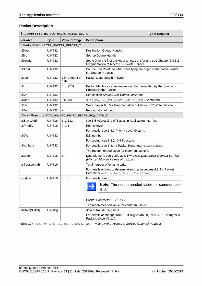
The Application Interface 288/390
sercos Master | Protocol API DOC081103API11EN | Revision 11 | English | 2013-09 | Released | Public © Hilscher, 2008-2013
Packet Description
Structure SIII_MA_SVC_MACRO_WRITE_REQ_T Type: Request
Variable Type Value / Range Description
tHead - Structure TLR_PACKET_HEADER_T
ulDest UINT32 Destination Queue-Handle
ulSrc UINT32 Source Queue-Handle
ulDestId UINT32 Set to 0 for the first packet of a new transfer and see Chapter 6.8.5.2 Fragmentation of Macro SVC Write Service
ulSrcId UINT32 Source End Point Identifier, specifying the origin of the packet inside the Source Process
ulLen UINT32 18+ amount of data
Packet Data Length in bytes
ulId UINT32 0 ... 232-1 Packet Identification as unique number generated by the Source Process of the Packet
ulSta UINT32 See section Status/Error Codes Overview
ulCmd UINT32 0x490A SIII_MA_SVC_CMD_MACRO_WRITE_REQ - Command
ulExt UINT32 See Chapter 6.8.5.2 Fragmentation of Macro SVC Write Service
ulRout UINT32 x Routing, do not touch
tData - Structure SIII_MA_SVC_MACRO_WRITE_REQ_DATA_T
usSlaveAddr UINT16 1 ... 511 see 5.5 Addressing of Slaves in Application Interface
usPriority UINT16 0 ... 1 Priority level
For details, see 6.8.2 Priority Level System.
ulIDN UINT32 IDN number
For coding, see 8.3.2 IDN Structure
ulAttribute UINT32 For details, see 6.8.4.1 Packet Parameter ulAttribute
The recommended value for common use is 0.
usElem UINT16 1, 7 Data element, see Table 223: Write IDN Data Block Element Service (Macro): Allowed Values of usElem
usTotalLength UINT16 Total number of bytes to write
For details on how to determine such a value, see 6.8.4.4 Packet Parameter usTotalLength / ulTotalLength.
usIsList UINT16 0 ... 3 For details, see 0
Note: The recommended value for common use is 0.
Packet Parameter usIsList.
The recommended value for common use is 3.
abData[384*4] UINT8[] data of transfer segment
For details of change from UINT16[] to UINT8[], see 6.8.1 Changes in Packets since V2.1.X.
Table 224: SIII_MA_SVC_CMD_MACRO_WRITE_REQ – Macro Write Access to Service Channel Request
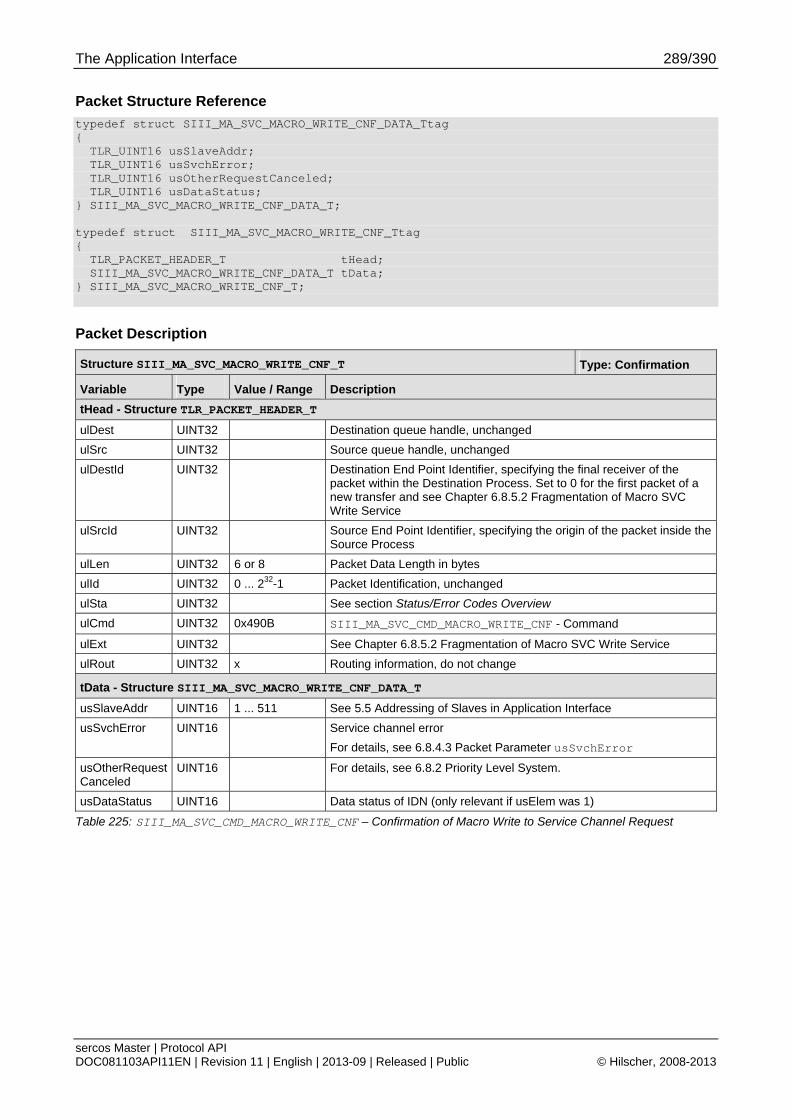
The Application Interface 289/390
sercos Master | Protocol API DOC081103API11EN | Revision 11 | English | 2013-09 | Released | Public © Hilscher, 2008-2013
Packet Structure Reference
typedef struct SIII_MA_SVC_MACRO_WRITE_CNF_DATA_Ttag { TLR_UINT16 usSlaveAddr; TLR_UINT16 usSvchError; TLR_UINT16 usOtherRequestCanceled; TLR_UINT16 usDataStatus; } SIII_MA_SVC_MACRO_WRITE_CNF_DATA_T; typedef struct SIII_MA_SVC_MACRO_WRITE_CNF_Ttag { TLR_PACKET_HEADER_T tHead; SIII_MA_SVC_MACRO_WRITE_CNF_DATA_T tData; } SIII_MA_SVC_MACRO_WRITE_CNF_T;
Packet Description
Structure SIII_MA_SVC_MACRO_WRITE_CNF_T Type: Confirmation
Variable Type Value / Range Description
tHead - Structure TLR_PACKET_HEADER_T
ulDest UINT32 Destination queue handle, unchanged
ulSrc UINT32 Source queue handle, unchanged
ulDestId UINT32 Destination End Point Identifier, specifying the final receiver of the packet within the Destination Process. Set to 0 for the first packet of a new transfer and see Chapter 6.8.5.2 Fragmentation of Macro SVC Write Service
ulSrcId UINT32 Source End Point Identifier, specifying the origin of the packet inside the Source Process
ulLen UINT32 6 or 8 Packet Data Length in bytes
ulId UINT32 0 ... 232-1 Packet Identification, unchanged
ulSta UINT32 See section Status/Error Codes Overview
ulCmd UINT32 0x490B SIII_MA_SVC_CMD_MACRO_WRITE_CNF - Command
ulExt UINT32 See Chapter 6.8.5.2 Fragmentation of Macro SVC Write Service
ulRout UINT32 x Routing information, do not change
tData - Structure SIII_MA_SVC_MACRO_WRITE_CNF_DATA_T
usSlaveAddr UINT16 1 ... 511 See 5.5 Addressing of Slaves in Application Interface
usSvchError UINT16 Service channel error
For details, see 6.8.4.3 Packet Parameter usSvchError
usOtherRequestCanceled
UINT16 For details, see 6.8.2 Priority Level System.
usDataStatus UINT16 Data status of IDN (only relevant if usElem was 1)
Table 225: SIII_MA_SVC_CMD_MACRO_WRITE_CNF – Confirmation of Macro Write to Service Channel Request
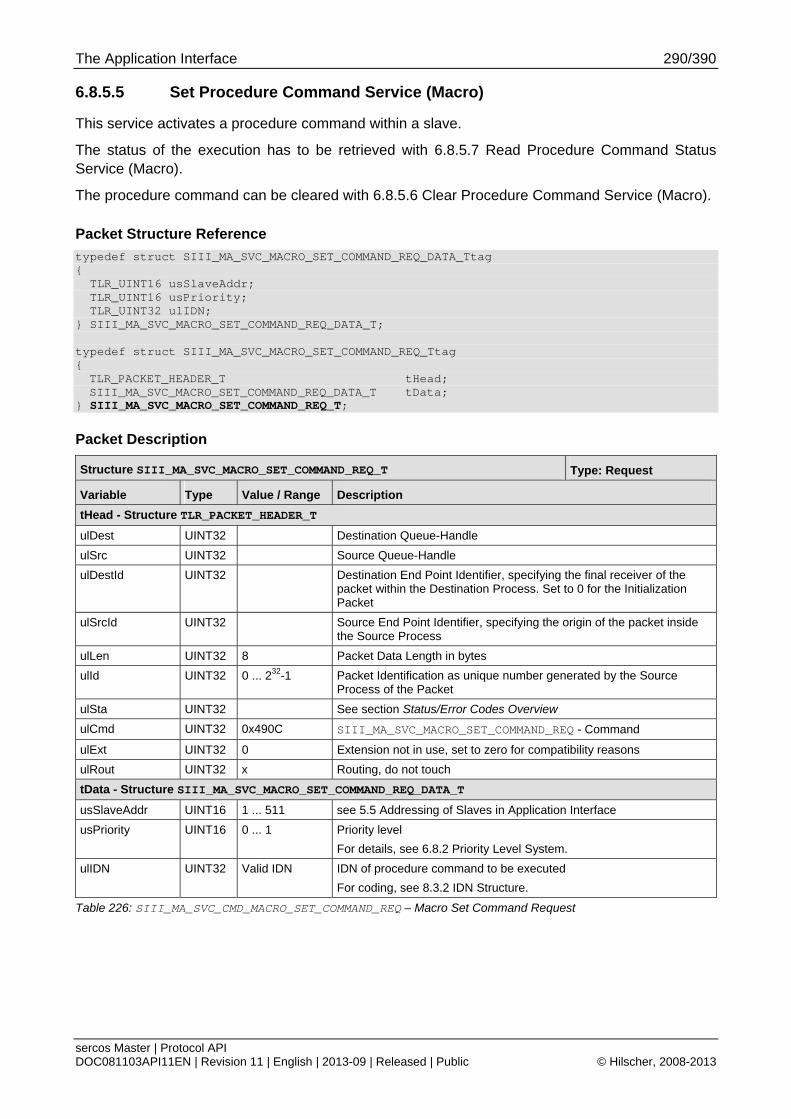
The Application Interface 290/390
sercos Master | Protocol API DOC081103API11EN | Revision 11 | English | 2013-09 | Released | Public © Hilscher, 2008-2013
6.8.5.5 Set Procedure Command Service (Macro)
This service activates a procedure command within a slave.
The status of the execution has to be retrieved with 6.8.5.7 Read Procedure Command Status Service (Macro).
The procedure command can be cleared with 6.8.5.6 Clear Procedure Command Service (Macro).
Packet Structure Reference
typedef struct SIII_MA_SVC_MACRO_SET_COMMAND_REQ_DATA_Ttag { TLR_UINT16 usSlaveAddr; TLR_UINT16 usPriority; TLR_UINT32 ulIDN; } SIII_MA_SVC_MACRO_SET_COMMAND_REQ_DATA_T; typedef struct SIII_MA_SVC_MACRO_SET_COMMAND_REQ_Ttag { TLR_PACKET_HEADER_T tHead; SIII_MA_SVC_MACRO_SET_COMMAND_REQ_DATA_T tData;
} SIII_MA_SVC_MACRO_SET_COMMAND_REQ_T;
Packet Description
Structure SIII_MA_SVC_MACRO_SET_COMMAND_REQ_T Type: Request
Variable Type Value / Range Description
tHead - Structure TLR_PACKET_HEADER_T
ulDest UINT32 Destination Queue-Handle
ulSrc UINT32 Source Queue-Handle
ulDestId UINT32 Destination End Point Identifier, specifying the final receiver of the packet within the Destination Process. Set to 0 for the Initialization Packet
ulSrcId UINT32 Source End Point Identifier, specifying the origin of the packet inside the Source Process
ulLen UINT32 8 Packet Data Length in bytes
ulId UINT32 0 ... 232-1 Packet Identification as unique number generated by the Source Process of the Packet
ulSta UINT32 See section Status/Error Codes Overview
ulCmd UINT32 0x490C SIII_MA_SVC_MACRO_SET_COMMAND_REQ - Command
ulExt UINT32 0 Extension not in use, set to zero for compatibility reasons
ulRout UINT32 x Routing, do not touch
tData - Structure SIII_MA_SVC_MACRO_SET_COMMAND_REQ_DATA_T
usSlaveAddr UINT16 1 ... 511 see 5.5 Addressing of Slaves in Application Interface
usPriority UINT16 0 ... 1 Priority level
For details, see 6.8.2 Priority Level System.
ulIDN UINT32 Valid IDN IDN of procedure command to be executed
For coding, see 8.3.2 IDN Structure.
Table 226: SIII_MA_SVC_CMD_MACRO_SET_COMMAND_REQ – Macro Set Command Request
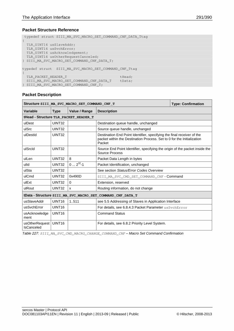
The Application Interface 291/390
sercos Master | Protocol API DOC081103API11EN | Revision 11 | English | 2013-09 | Released | Public © Hilscher, 2008-2013
Packet Structure Reference
typedef struct SIII_MA_SVC_MACRO_SET_COMMAND_CNF_DATA_Ttag { TLR_UINT16 usSlaveAddr; TLR_UINT16 usSvchError; TLR_UINT16 usAcknowledgement; TLR_UINT16 usOtherRequestCanceled; } SIII_MA_SVC_MACRO_SET_COMMAND_CNF_DATA_T; typedef struct SIII_MA_SVC_MACRO_SET_COMMAND_CNF_Ttag { TLR_PACKET_HEADER_T tHead; SIII_MA_SVC_MACRO_SET_COMMAND_CNF_DATA_T tData; } SIII_MA_SVC_MACRO_SET_COMMAND_CNF_T;
Packet Description
Structure SIII_MA_SVC_MACRO_SET_COMMAND_CNF_T Type: Confirmation
Variable Type Value / Range Description
tHead - Structure TLR_PACKET_HEADER_T
ulDest UINT32 Destination queue handle, unchanged
ulSrc UINT32 Source queue handle, unchanged
ulDestId UINT32 Destination End Point Identifier, specifying the final receiver of the packet within the Destination Process. Set to 0 for the Initialization Packet
ulSrcId UINT32 Source End Point Identifier, specifying the origin of the packet inside the Source Process
ulLen UINT32 8 Packet Data Length in bytes
ulId UINT32 0 ... 232-1 Packet Identification, unchanged
ulSta UINT32 See section Status/Error Codes Overview
ulCmd UINT32 0x490D SIII_MA_SVC_CMD_SET_COMMAND_CNF - Command
ulExt UINT32 0 Extension, reserved
ulRout UINT32 x Routing information, do not change
tData - Structure SIII_MA_SVC_MACRO_SET_COMMAND_CNF_DATA_T
usSlaveAddr UINT16 1..511 see 5.5 Addressing of Slaves in Application Interface
usSvchError UINT16 For details, see 6.8.4.3 Packet Parameter usSvchError
usAcknowledgement
UINT16 Command Status
usOtherRequestIsCanceled
UINT16 For details, see 6.8.2 Priority Level System.
Table 227: SIII_MA_SVC_CMD_MACRO_CHANGE_COMMAND_CNF – Macro Set Command Confirmation
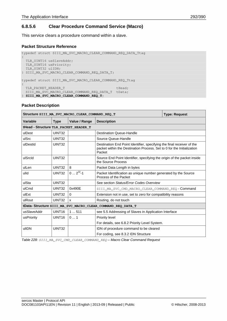
The Application Interface 292/390
sercos Master | Protocol API DOC081103API11EN | Revision 11 | English | 2013-09 | Released | Public © Hilscher, 2008-2013
6.8.5.6 Clear Procedure Command Service (Macro)
This service clears a procedure command within a slave.
Packet Structure Reference
typedef struct SIII_MA_SVC_MACRO_CLEAR_COMMAND_REQ_DATA_Ttag { TLR_UINT16 usSlaveAddr; TLR_UINT16 usPriority; TLR_UINT32 ulIDN; } SIII_MA_SVC_MACRO_CLEAR_COMMAND_REQ_DATA_T; typedef struct SIII_MA_SVC_MACRO_CLEAR_COMMAND_REQ_Ttag { TLR_PACKET_HEADER_T tHead; SIII_MA_SVC_MACRO_CLEAR_COMMAND_REQ_DATA_T tData;
} SIII_MA_SVC_MACRO_CLEAR_COMMAND_REQ_T;
Packet Description
Structure SIII_MA_SVC_MACRO_CLEAR_COMMAND_REQ_T Type: Request
Variable Type Value / Range Description
tHead - Structure TLR_PACKET_HEADER_T
ulDest UINT32 Destination Queue-Handle
ulSrc UINT32 Source Queue-Handle
ulDestId UINT32 Destination End Point Identifier, specifying the final receiver of the packet within the Destination Process. Set to 0 for the Initialization Packet
ulSrcId UINT32 Source End Point Identifier, specifying the origin of the packet inside the Source Process
ulLen UINT32 8 Packet Data Length in bytes
ulId UINT32 0 ... 232-1 Packet Identification as unique number generated by the Source Process of the Packet
ulSta UINT32 See section Status/Error Codes Overview
ulCmd UINT32 0x490E SIII_MA_SVC_CMD_MACRO_CLEAR_COMMAND_REQ - Command
ulExt UINT32 0 Extension not in use, set to zero for compatibility reasons
ulRout UINT32 x Routing, do not touch
tData- Structure SIII_MA_SVC_MACRO_CLEAR_COMMAND_REQ_DATA_T
usSlaveAddr UINT16 1 ... 511 see 5.5 Addressing of Slaves in Application Interface
usPriority UINT16 0 ... 1 Priority level
For details, see 6.8.2 Priority Level System.
ulIDN UINT32 IDN of procedure command to be cleared
For coding, see 8.3.2 IDN Structure
Table 228: SIII_MA_SVC_CMD_CLEAR_COMMAND_REQ – Macro Clear Command Request
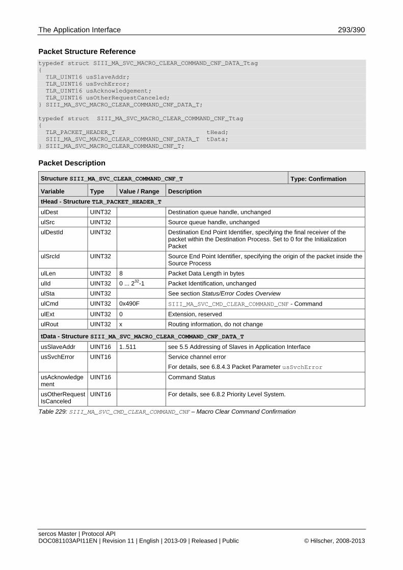
The Application Interface 293/390
sercos Master | Protocol API DOC081103API11EN | Revision 11 | English | 2013-09 | Released | Public © Hilscher, 2008-2013
Packet Structure Reference
typedef struct SIII_MA_SVC_MACRO_CLEAR_COMMAND_CNF_DATA_Ttag { TLR_UINT16 usSlaveAddr; TLR_UINT16 usSvchError; TLR_UINT16 usAcknowledgement; TLR_UINT16 usOtherRequestCanceled; } SIII_MA_SVC_MACRO_CLEAR_COMMAND_CNF_DATA_T; typedef struct SIII_MA_SVC_MACRO_CLEAR_COMMAND_CNF_Ttag { TLR_PACKET_HEADER_T tHead; SIII_MA_SVC_MACRO_CLEAR_COMMAND_CNF_DATA_T tData; } SIII_MA_SVC_MACRO_CLEAR_COMMAND_CNF_T;
Packet Description
Structure SIII_MA_SVC_CLEAR_COMMAND_CNF_T Type: Confirmation
Variable Type Value / Range Description
tHead - Structure TLR_PACKET_HEADER_T
ulDest UINT32 Destination queue handle, unchanged
ulSrc UINT32 Source queue handle, unchanged
ulDestId UINT32 Destination End Point Identifier, specifying the final receiver of the packet within the Destination Process. Set to 0 for the Initialization Packet
ulSrcId UINT32 Source End Point Identifier, specifying the origin of the packet inside the Source Process
ulLen UINT32 8 Packet Data Length in bytes
ulId UINT32 0 ... 232-1 Packet Identification, unchanged
ulSta UINT32 See section Status/Error Codes Overview
ulCmd UINT32 0x490F SIII_MA_SVC_CMD_CLEAR_COMMAND_CNF - Command
ulExt UINT32 0 Extension, reserved
ulRout UINT32 x Routing information, do not change
tData - Structure SIII_MA_SVC_MACRO_CLEAR_COMMAND_CNF_DATA_T
usSlaveAddr UINT16 1..511 see 5.5 Addressing of Slaves in Application Interface
usSvchError UINT16 Service channel error
For details, see 6.8.4.3 Packet Parameter usSvchError
usAcknowledgement
UINT16 Command Status
usOtherRequestIsCanceled
UINT16 For details, see 6.8.2 Priority Level System.
Table 229: SIII_MA_SVC_CMD_CLEAR_COMMAND_CNF – Macro Clear Command Confirmation
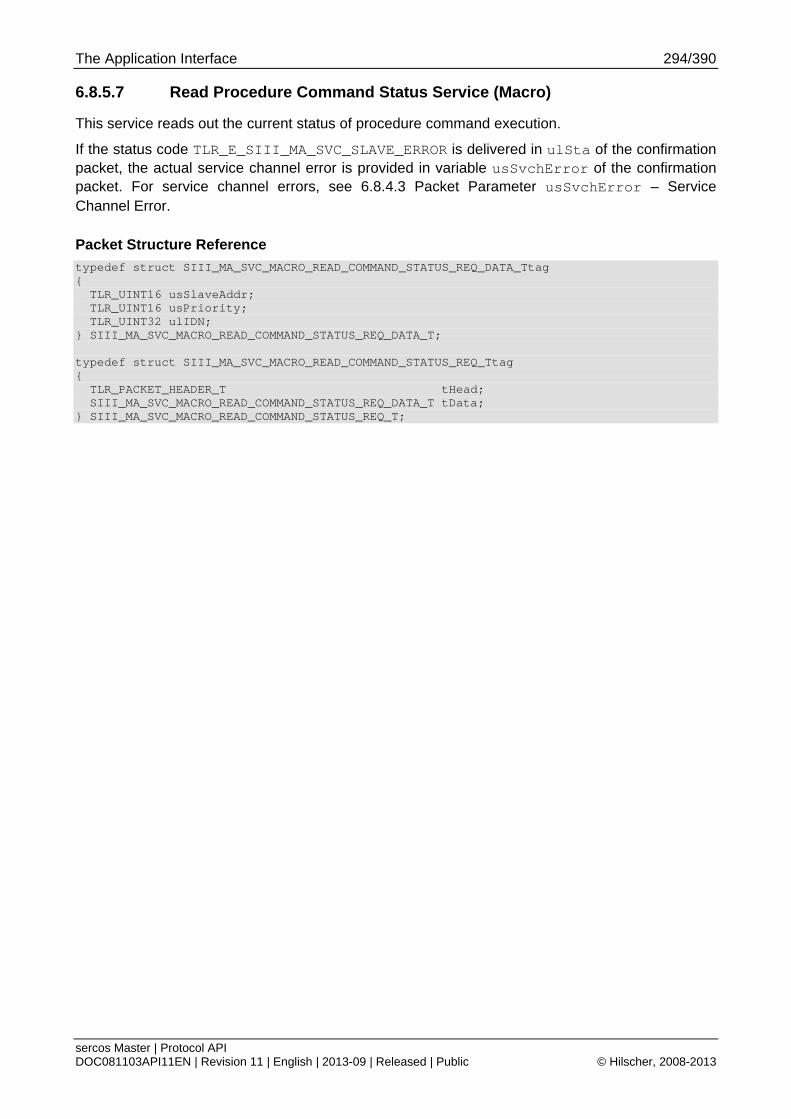
The Application Interface 294/390
sercos Master | Protocol API DOC081103API11EN | Revision 11 | English | 2013-09 | Released | Public © Hilscher, 2008-2013
6.8.5.7 Read Procedure Command Status Service (Macro)
This service reads out the current status of procedure command execution.
If the status code TLR_E_SIII_MA_SVC_SLAVE_ERROR is delivered in ulSta of the confirmation packet, the actual service channel error is provided in variable usSvchError of the confirmation packet. For service channel errors, see 6.8.4.3 Packet Parameter usSvchError – Service Channel Error.
Packet Structure Reference
typedef struct SIII_MA_SVC_MACRO_READ_COMMAND_STATUS_REQ_DATA_Ttag { TLR_UINT16 usSlaveAddr; TLR_UINT16 usPriority; TLR_UINT32 ulIDN; } SIII_MA_SVC_MACRO_READ_COMMAND_STATUS_REQ_DATA_T; typedef struct SIII_MA_SVC_MACRO_READ_COMMAND_STATUS_REQ_Ttag { TLR_PACKET_HEADER_T tHead; SIII_MA_SVC_MACRO_READ_COMMAND_STATUS_REQ_DATA_T tData; } SIII_MA_SVC_MACRO_READ_COMMAND_STATUS_REQ_T;
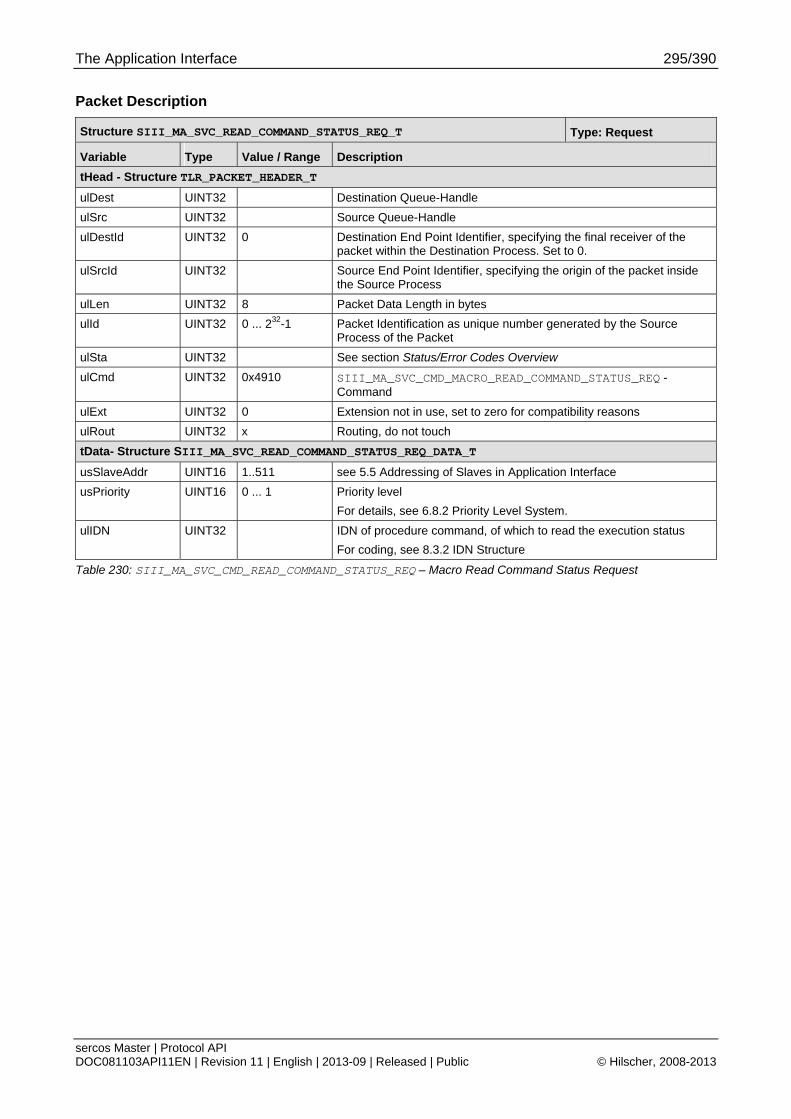
The Application Interface 295/390
sercos Master | Protocol API DOC081103API11EN | Revision 11 | English | 2013-09 | Released | Public © Hilscher, 2008-2013
Packet Description
Structure SIII_MA_SVC_READ_COMMAND_STATUS_REQ_T Type: Request
Variable Type Value / Range Description
tHead - Structure TLR_PACKET_HEADER_T
ulDest UINT32 Destination Queue-Handle
ulSrc UINT32 Source Queue-Handle
ulDestId UINT32 0 Destination End Point Identifier, specifying the final receiver of the packet within the Destination Process. Set to 0.
ulSrcId UINT32 Source End Point Identifier, specifying the origin of the packet inside the Source Process
ulLen UINT32 8 Packet Data Length in bytes
ulId UINT32 0 ... 232-1 Packet Identification as unique number generated by the Source Process of the Packet
ulSta UINT32 See section Status/Error Codes Overview
ulCmd UINT32 0x4910 SIII_MA_SVC_CMD_MACRO_READ_COMMAND_STATUS_REQ - Command
ulExt UINT32 0 Extension not in use, set to zero for compatibility reasons
ulRout UINT32 x Routing, do not touch
tData- Structure SIII_MA_SVC_READ_COMMAND_STATUS_REQ_DATA_T
usSlaveAddr UINT16 1..511 see 5.5 Addressing of Slaves in Application Interface
usPriority UINT16 0 ... 1 Priority level
For details, see 6.8.2 Priority Level System.
ulIDN UINT32 IDN of procedure command, of which to read the execution status
For coding, see 8.3.2 IDN Structure
Table 230: SIII_MA_SVC_CMD_READ_COMMAND_STATUS_REQ – Macro Read Command Status Request
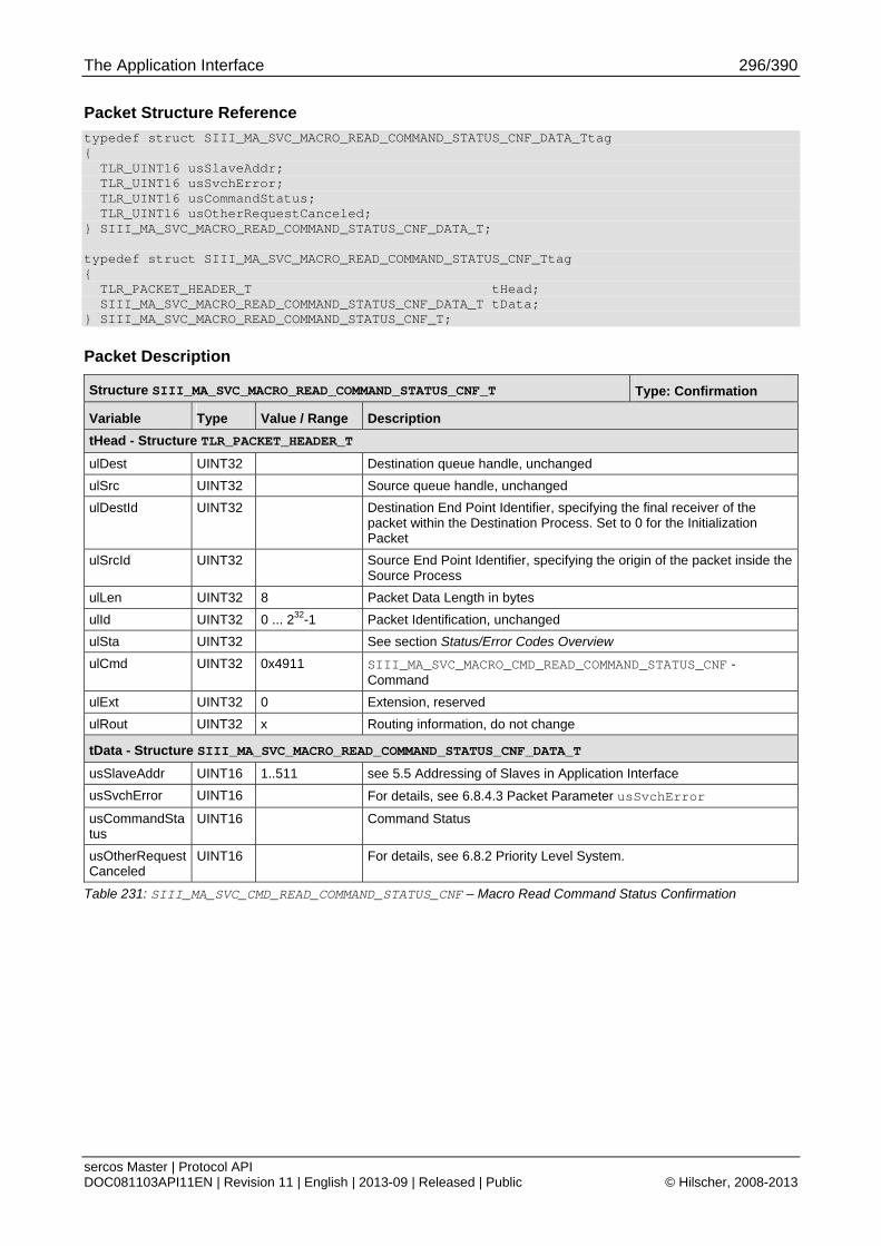
The Application Interface 296/390
sercos Master | Protocol API DOC081103API11EN | Revision 11 | English | 2013-09 | Released | Public © Hilscher, 2008-2013
Packet Structure Reference
typedef struct SIII_MA_SVC_MACRO_READ_COMMAND_STATUS_CNF_DATA_Ttag { TLR_UINT16 usSlaveAddr; TLR_UINT16 usSvchError; TLR_UINT16 usCommandStatus; TLR_UINT16 usOtherRequestCanceled; } SIII_MA_SVC_MACRO_READ_COMMAND_STATUS_CNF_DATA_T; typedef struct SIII_MA_SVC_MACRO_READ_COMMAND_STATUS_CNF_Ttag { TLR_PACKET_HEADER_T tHead; SIII_MA_SVC_MACRO_READ_COMMAND_STATUS_CNF_DATA_T tData; } SIII_MA_SVC_MACRO_READ_COMMAND_STATUS_CNF_T;
Packet Description
Structure SIII_MA_SVC_MACRO_READ_COMMAND_STATUS_CNF_T Type: Confirmation
Variable Type Value / Range Description
tHead - Structure TLR_PACKET_HEADER_T
ulDest UINT32 Destination queue handle, unchanged
ulSrc UINT32 Source queue handle, unchanged
ulDestId UINT32 Destination End Point Identifier, specifying the final receiver of the packet within the Destination Process. Set to 0 for the Initialization Packet
ulSrcId UINT32 Source End Point Identifier, specifying the origin of the packet inside the Source Process
ulLen UINT32 8 Packet Data Length in bytes
ulId UINT32 0 ... 232-1 Packet Identification, unchanged
ulSta UINT32 See section Status/Error Codes Overview
ulCmd UINT32 0x4911 SIII_MA_SVC_MACRO_CMD_READ_COMMAND_STATUS_CNF - Command
ulExt UINT32 0 Extension, reserved
ulRout UINT32 x Routing information, do not change
tData - Structure SIII_MA_SVC_MACRO_READ_COMMAND_STATUS_CNF_DATA_T
usSlaveAddr UINT16 1..511 see 5.5 Addressing of Slaves in Application Interface
usSvchError UINT16 For details, see 6.8.4.3 Packet Parameter usSvchError
usCommandStatus
UINT16 Command Status
usOtherRequestCanceled
UINT16 For details, see 6.8.2 Priority Level System.
Table 231: SIII_MA_SVC_CMD_READ_COMMAND_STATUS_CNF – Macro Read Command Status Confirmation
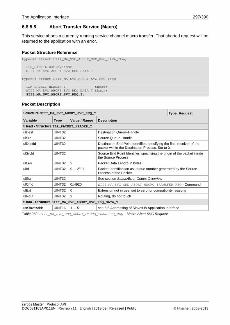
The Application Interface 297/390
sercos Master | Protocol API DOC081103API11EN | Revision 11 | English | 2013-09 | Released | Public © Hilscher, 2008-2013
6.8.5.8 Abort Transfer Service (Macro)
This service aborts a currently running service channel macro transfer. That aborted request will be returned to the application with an error.
Packet Structure Reference
typedef struct SIII_MA_SVC_ABORT_SVC_REQ_DATA_Ttag { TLR_UINT16 usSlaveAddr;
} SIII_MA_SVC_ABORT_SVC_REQ_DATA_T; typedef struct SIII_MA_SVC_ABORT_SVC_REQ_Ttag { TLR_PACKET_HEADER_T tHead; SIII_MA_SVC_ABORT_SVC_REQ_DATA_T tData;
} SIII_MA_SVC_ABORT_SVC_REQ_T;
Packet Description
Structure SIII_MA_SVC_ABORT_SVC_REQ_T Type: Request
Variable Type Value / Range Description
tHead - Structure TLR_PACKET_HEADER_T
ulDest UINT32 Destination Queue-Handle
ulSrc UINT32 Source Queue-Handle
ulDestId UINT32 Destination End Point Identifier, specifying the final receiver of the packet within the Destination Process. Set to 0.
ulSrcId UINT32 Source End Point Identifier, specifying the origin of the packet inside the Source Process
ulLen UINT32 2 Packet Data Length in bytes
ulId UINT32 0 ... 232-1 Packet Identification as unique number generated by the Source Process of the Packet
ulSta UINT32 See section Status/Error Codes Overview
ulCmd UINT32 0x4920 SIII_MA_SVC_CMD_ABORT_MACRO_TRANSFER_REQ - Command
ulExt UINT32 0 Extension not in use, set to zero for compatibility reasons
ulRout UINT32 x Routing, do not touch
tData - Structure SIII_MA_SVC_ABORT_SVC_REQ_DATA_T
usSlaveAddr UINT16 1 ... 511 see 5.5 Addressing of Slaves in Application Interface
Table 232: SIII_MA_SVC_CMD_ABORT_MACRO_TRANSFER_REQ – Macro Abort SVC Request
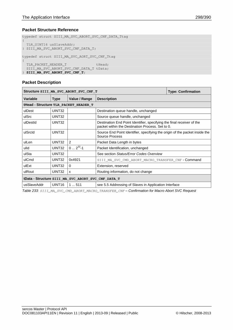
The Application Interface 298/390
sercos Master | Protocol API DOC081103API11EN | Revision 11 | English | 2013-09 | Released | Public © Hilscher, 2008-2013
Packet Structure Reference
typedef struct SIII_MA_SVC_ABORT_SVC_CNF_DATA_Ttag { TLR_UINT16 usSlaveAddr; } SIII_MA_SVC_ABORT_SVC_CNF_DATA_T; typedef struct SIII_MA_SVC_AORT_SVC_CNF_Ttag { TLR_PACKET_HEADER_T tHead; SIII_MA_SVC_ABORT_SVC_CNF_DATA_T tData; } SIII_MA_SVC_ABORT_SVC_CNF_T;
Packet Description
Structure SIII_MA_SVC_ABORT_SVC_CNF_T Type: Confirmation
Variable Type Value / Range Description
tHead - Structure TLR_PACKET_HEADER_T
ulDest UINT32 Destination queue handle, unchanged
ulSrc UINT32 Source queue handle, unchanged
ulDestId UINT32 Destination End Point Identifier, specifying the final receiver of the packet within the Destination Process. Set to 0.
ulSrcId UINT32 Source End Point Identifier, specifying the origin of the packet inside the Source Process
ulLen UINT32 2 Packet Data Length in bytes
ulId UINT32 0 ... 232-1 Packet Identification, unchanged
ulSta UINT32 See section Status/Error Codes Overview
ulCmd UINT32 0x4921 SIII_MA_SVC_CMD_ABORT_MACRO_TRANSFER_CNF - Command
ulExt UINT32 0 Extension, reserved
ulRout UINT32 x Routing information, do not change
tData - Structure SIII_MA_SVC_ABORT_SVC_CNF_DATA_T
usSlaveAddr UINT16 1 ... 511 see 5.5 Addressing of Slaves in Application Interface
Table 233: SIII_MA_SVC_CMD_ABORT_MACRO_TRANSFER_CNF – Confirmation for Macro Abort SVC Request
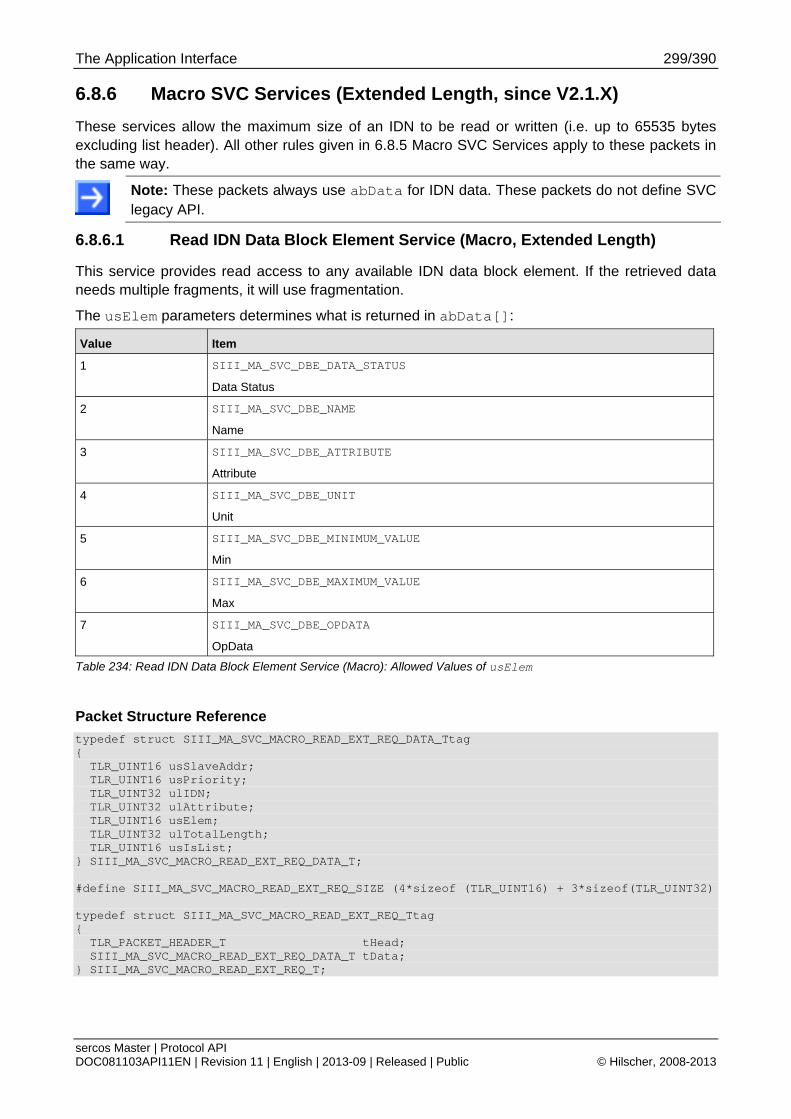
The Application Interface 299/390
sercos Master | Protocol API DOC081103API11EN | Revision 11 | English | 2013-09 | Released | Public © Hilscher, 2008-2013
6.8.6 Macro SVC Services (Extended Length, since V2.1.X)
These services allow the maximum size of an IDN to be read or written (i.e. up to 65535 bytes excluding list header). All other rules given in 6.8.5 Macro SVC Services apply to these packets in the same way.
Note: These packets always use abData for IDN data. These packets do not define SVC legacy API.
6.8.6.1 Read IDN Data Block Element Service (Macro, Extended Length)
This service provides read access to any available IDN data block element. If the retrieved data needs multiple fragments, it will use fragmentation.
The usElem parameters determines what is returned in abData[]:
Value Item
1 SIII_MA_SVC_DBE_DATA_STATUS
Data Status
2 SIII_MA_SVC_DBE_NAME
Name
3 SIII_MA_SVC_DBE_ATTRIBUTE
Attribute
4 SIII_MA_SVC_DBE_UNIT
Unit
5 SIII_MA_SVC_DBE_MINIMUM_VALUE
Min
6 SIII_MA_SVC_DBE_MAXIMUM_VALUE
Max
7 SIII_MA_SVC_DBE_OPDATA
OpData
Table 234: Read IDN Data Block Element Service (Macro): Allowed Values of usElem
Packet Structure Reference
typedef struct SIII_MA_SVC_MACRO_READ_EXT_REQ_DATA_Ttag { TLR_UINT16 usSlaveAddr; TLR_UINT16 usPriority; TLR_UINT32 ulIDN; TLR_UINT32 ulAttribute; TLR_UINT16 usElem; TLR_UINT32 ulTotalLength; TLR_UINT16 usIsList; } SIII_MA_SVC_MACRO_READ_EXT_REQ_DATA_T; #define SIII_MA_SVC_MACRO_READ_EXT_REQ_SIZE (4*sizeof (TLR_UINT16) + 3*sizeof(TLR_UINT32) typedef struct SIII_MA_SVC_MACRO_READ_EXT_REQ_Ttag { TLR_PACKET_HEADER_T tHead; SIII_MA_SVC_MACRO_READ_EXT_REQ_DATA_T tData; } SIII_MA_SVC_MACRO_READ_EXT_REQ_T;
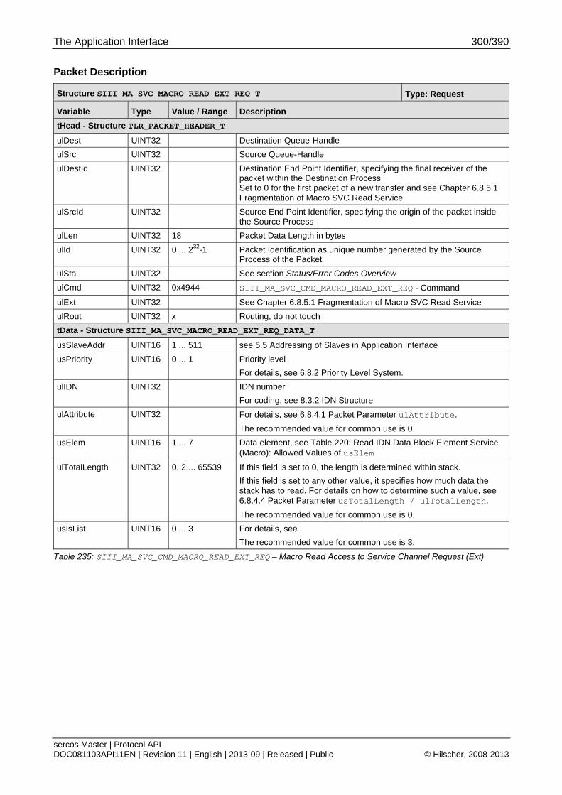
The Application Interface 300/390
sercos Master | Protocol API DOC081103API11EN | Revision 11 | English | 2013-09 | Released | Public © Hilscher, 2008-2013
Packet Description
Structure SIII_MA_SVC_MACRO_READ_EXT_REQ_T Type: Request
Variable Type Value / Range Description
tHead - Structure TLR_PACKET_HEADER_T
ulDest UINT32 Destination Queue-Handle
ulSrc UINT32 Source Queue-Handle
ulDestId UINT32 Destination End Point Identifier, specifying the final receiver of the packet within the Destination Process. Set to 0 for the first packet of a new transfer and see Chapter 6.8.5.1 Fragmentation of Macro SVC Read Service
ulSrcId UINT32 Source End Point Identifier, specifying the origin of the packet inside the Source Process
ulLen UINT32 18 Packet Data Length in bytes
ulId UINT32 0 ... 232-1 Packet Identification as unique number generated by the Source Process of the Packet
ulSta UINT32 See section Status/Error Codes Overview
ulCmd UINT32 0x4944 SIII_MA_SVC_CMD_MACRO_READ_EXT_REQ - Command
ulExt UINT32 See Chapter 6.8.5.1 Fragmentation of Macro SVC Read Service
ulRout UINT32 x Routing, do not touch
tData - Structure SIII_MA_SVC_MACRO_READ_EXT_REQ_DATA_T
usSlaveAddr UINT16 1 ... 511 see 5.5 Addressing of Slaves in Application Interface
usPriority UINT16 0 ... 1 Priority level
For details, see 6.8.2 Priority Level System.
ulIDN UINT32 IDN number
For coding, see 8.3.2 IDN Structure
ulAttribute UINT32 For details, see 6.8.4.1 Packet Parameter ulAttribute.
The recommended value for common use is 0.
usElem UINT16 1 ... 7 Data element, see Table 220: Read IDN Data Block Element Service (Macro): Allowed Values of usElem
ulTotalLength UINT32 0, 2 ... 65539 If this field is set to 0, the length is determined within stack.
If this field is set to any other value, it specifies how much data the stack has to read. For details on how to determine such a value, see 6.8.4.4 Packet Parameter usTotalLength / ulTotalLength.
The recommended value for common use is 0.
usIsList UINT16 0 ... 3 For details, see
The recommended value for common use is 3.
Table 235: SIII_MA_SVC_CMD_MACRO_READ_EXT_REQ – Macro Read Access to Service Channel Request (Ext)
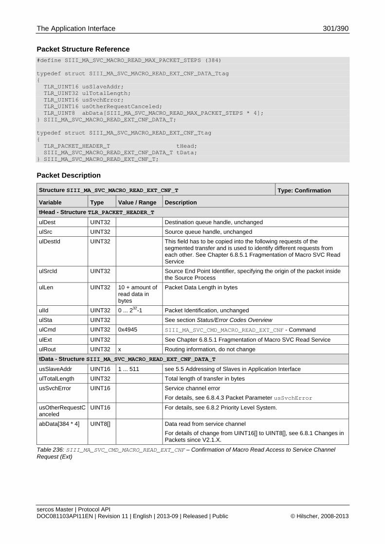
The Application Interface 301/390
sercos Master | Protocol API DOC081103API11EN | Revision 11 | English | 2013-09 | Released | Public © Hilscher, 2008-2013
Packet Structure Reference
#define SIII_MA_SVC_MACRO_READ_MAX_PACKET_STEPS (384) typedef struct SIII_MA_SVC_MACRO_READ_EXT_CNF_DATA_Ttag { TLR_UINT16 usSlaveAddr; TLR_UINT32 ulTotalLength; TLR_UINT16 usSvchError; TLR_UINT16 usOtherRequestCanceled; TLR_UINT8 abData[SIII_MA_SVC_MACRO_READ_MAX_PACKET_STEPS * 4]; } SIII_MA_SVC_MACRO_READ_EXT_CNF_DATA_T; typedef struct SIII_MA_SVC_MACRO_READ_EXT_CNF_Ttag { TLR_PACKET_HEADER_T tHead; SIII_MA_SVC_MACRO_READ_EXT_CNF_DATA_T tData; } SIII_MA_SVC_MACRO_READ_EXT_CNF_T;
Packet Description
Structure SIII_MA_SVC_MACRO_READ_EXT_CNF_T Type: Confirmation
Variable Type Value / Range Description
tHead - Structure TLR_PACKET_HEADER_T
ulDest UINT32 Destination queue handle, unchanged
ulSrc UINT32 Source queue handle, unchanged
ulDestId UINT32 This field has to be copied into the following requests of the segmented transfer and is used to identify different requests from each other. See Chapter 6.8.5.1 Fragmentation of Macro SVC Read Service
ulSrcId UINT32 Source End Point Identifier, specifying the origin of the packet inside the Source Process
ulLen UINT32 10 + amount of read data in bytes
Packet Data Length in bytes
ulId UINT32 0 ... 232-1 Packet Identification, unchanged
ulSta UINT32 See section Status/Error Codes Overview
ulCmd UINT32 0x4945 SIII_MA_SVC_CMD_MACRO_READ_EXT_CNF - Command
ulExt UINT32 See Chapter 6.8.5.1 Fragmentation of Macro SVC Read Service
ulRout UINT32 x Routing information, do not change
tData - Structure SIII_MA_SVC_MACRO_READ_EXT_CNF_DATA_T
usSlaveAddr UINT16 1 ... 511 see 5.5 Addressing of Slaves in Application Interface
ulTotalLength UINT32 Total length of transfer in bytes
usSvchError UINT16 Service channel error
For details, see 6.8.4.3 Packet Parameter usSvchError
usOtherRequestCanceled
UINT16 For details, see 6.8.2 Priority Level System.
abData[384 * 4] UINT8[] Data read from service channel
For details of change from UINT16[] to UINT8[], see 6.8.1 Changes in Packets since V2.1.X.
Table 236: SIII_MA_SVC_CMD_MACRO_READ_EXT_CNF – Confirmation of Macro Read Access to Service Channel Request (Ext)
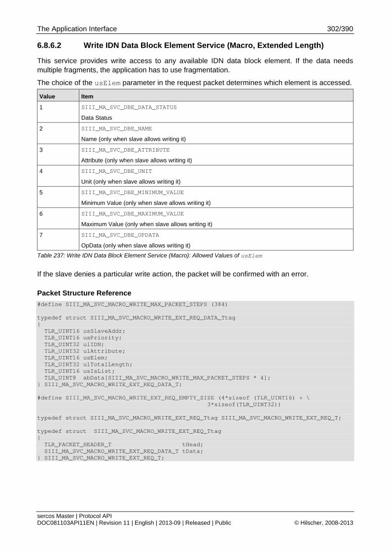
The Application Interface 302/390
sercos Master | Protocol API DOC081103API11EN | Revision 11 | English | 2013-09 | Released | Public © Hilscher, 2008-2013
6.8.6.2 Write IDN Data Block Element Service (Macro, Extended Length)
This service provides write access to any available IDN data block element. If the data needs multiple fragments, the application has to use fragmentation.
The choice of the usElem parameter in the request packet determines which element is accessed.
Value Item
1 SIII_MA_SVC_DBE_DATA_STATUS
Data Status
2 SIII_MA_SVC_DBE_NAME
Name (only when slave allows writing it)
3 SIII_MA_SVC_DBE_ATTRIBUTE
Attribute (only when slave allows writing it)
4 SIII_MA_SVC_DBE_UNIT
Unit (only when slave allows writing it)
5 SIII_MA_SVC_DBE_MINIMUM_VALUE
Minimum Value (only when slave allows writing it)
6 SIII_MA_SVC_DBE_MAXIMUM_VALUE
Maximum Value (only when slave allows writing it)
7 SIII_MA_SVC_DBE_OPDATA
OpData (only when slave allows writing it)
Table 237: Write IDN Data Block Element Service (Macro): Allowed Values of usElem
If the slave denies a particular write action, the packet will be confirmed with an error.
Packet Structure Reference
#define SIII_MA_SVC_MACRO_WRITE_MAX_PACKET_STEPS (384) typedef struct SIII_MA_SVC_MACRO_WRITE_EXT_REQ_DATA_Ttag { TLR_UINT16 usSlaveAddr; TLR_UINT16 usPriority; TLR_UINT32 ulIDN; TLR_UINT32 ulAttribute; TLR_UINT16 usElem; TLR_UINT32 ulTotalLength; TLR_UINT16 usIsList; TLR_UINT8 abData[SIII_MA_SVC_MACRO_WRITE_MAX_PACKET_STEPS * 4]; } SIII_MA_SVC_MACRO_WRITE_EXT_REQ_DATA_T; #define SIII_MA_SVC_MACRO_WRITE_EXT_REQ_EMPTY_SIZE (4*sizeof (TLR_UINT16) + \ 3*sizeof(TLR_UINT32)) typedef struct SIII_MA_SVC_MACRO_WRITE_EXT_REQ_Ttag SIII_MA_SVC_MACRO_WRITE_EXT_REQ_T; typedef struct SIII_MA_SVC_MACRO_WRITE_EXT_REQ_Ttag { TLR_PACKET_HEADER_T tHead; SIII_MA_SVC_MACRO_WRITE_EXT_REQ_DATA_T tData; } SIII_MA_SVC_MACRO_WRITE_EXT_REQ_T;
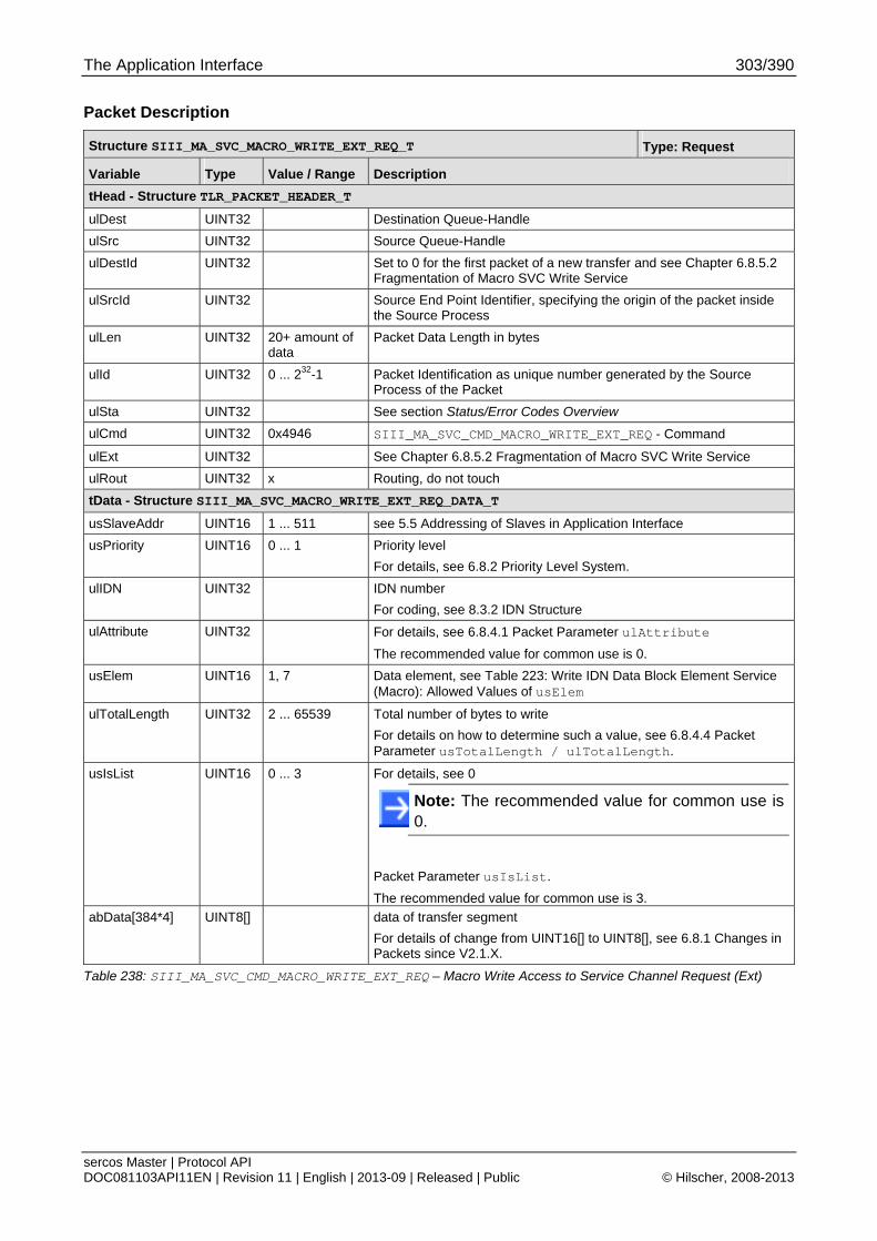
The Application Interface 303/390
sercos Master | Protocol API DOC081103API11EN | Revision 11 | English | 2013-09 | Released | Public © Hilscher, 2008-2013
Packet Description
Structure SIII_MA_SVC_MACRO_WRITE_EXT_REQ_T Type: Request
Variable Type Value / Range Description
tHead - Structure TLR_PACKET_HEADER_T
ulDest UINT32 Destination Queue-Handle
ulSrc UINT32 Source Queue-Handle
ulDestId UINT32 Set to 0 for the first packet of a new transfer and see Chapter 6.8.5.2 Fragmentation of Macro SVC Write Service
ulSrcId UINT32 Source End Point Identifier, specifying the origin of the packet inside the Source Process
ulLen UINT32 20+ amount of data
Packet Data Length in bytes
ulId UINT32 0 ... 232-1 Packet Identification as unique number generated by the Source Process of the Packet
ulSta UINT32 See section Status/Error Codes Overview
ulCmd UINT32 0x4946 SIII_MA_SVC_CMD_MACRO_WRITE_EXT_REQ - Command
ulExt UINT32 See Chapter 6.8.5.2 Fragmentation of Macro SVC Write Service
ulRout UINT32 x Routing, do not touch
tData - Structure SIII_MA_SVC_MACRO_WRITE_EXT_REQ_DATA_T
usSlaveAddr UINT16 1 ... 511 see 5.5 Addressing of Slaves in Application Interface
usPriority UINT16 0 ... 1 Priority level
For details, see 6.8.2 Priority Level System.
ulIDN UINT32 IDN number
For coding, see 8.3.2 IDN Structure
ulAttribute UINT32 For details, see 6.8.4.1 Packet Parameter ulAttribute
The recommended value for common use is 0.
usElem UINT16 1, 7 Data element, see Table 223: Write IDN Data Block Element Service (Macro): Allowed Values of usElem
ulTotalLength UINT32 2 ... 65539 Total number of bytes to write
For details on how to determine such a value, see 6.8.4.4 Packet Parameter usTotalLength / ulTotalLength.
usIsList UINT16 0 ... 3 For details, see 0
Note: The recommended value for common use is 0.
Packet Parameter usIsList.
The recommended value for common use is 3.
abData[384*4] UINT8[] data of transfer segment
For details of change from UINT16[] to UINT8[], see 6.8.1 Changes in Packets since V2.1.X.
Table 238: SIII_MA_SVC_CMD_MACRO_WRITE_EXT_REQ – Macro Write Access to Service Channel Request (Ext)
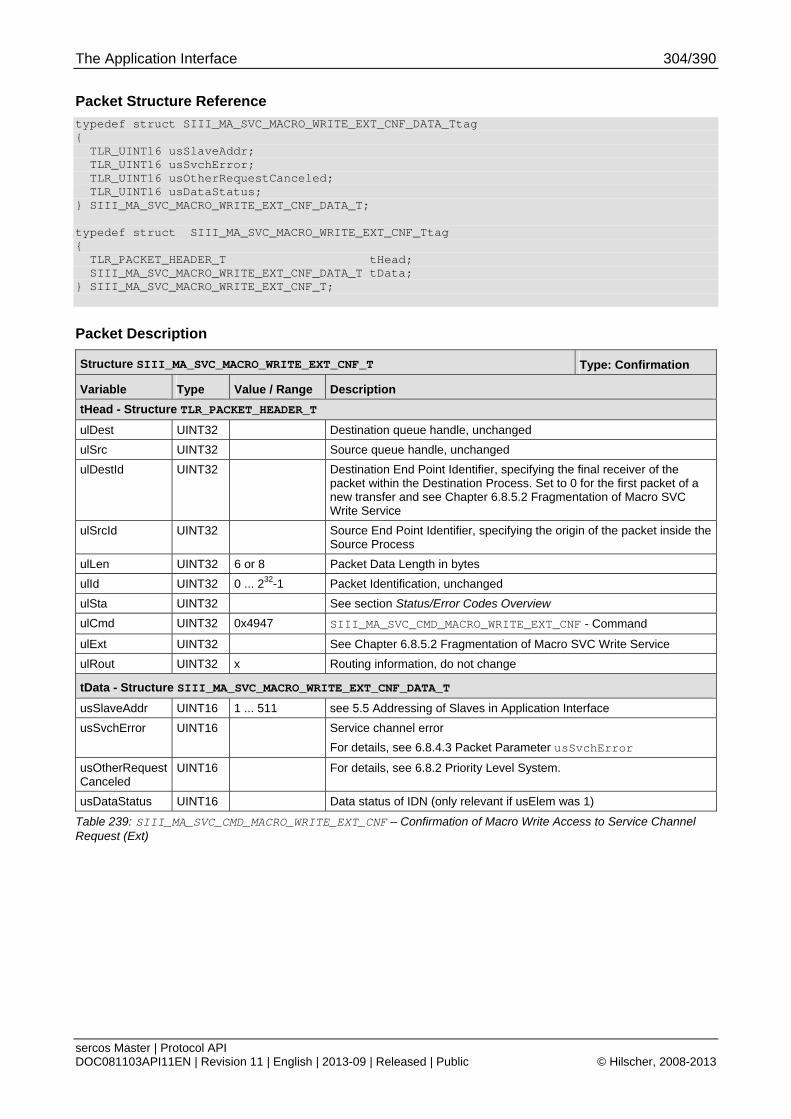
The Application Interface 304/390
sercos Master | Protocol API DOC081103API11EN | Revision 11 | English | 2013-09 | Released | Public © Hilscher, 2008-2013
Packet Structure Reference
typedef struct SIII_MA_SVC_MACRO_WRITE_EXT_CNF_DATA_Ttag { TLR_UINT16 usSlaveAddr; TLR_UINT16 usSvchError; TLR_UINT16 usOtherRequestCanceled; TLR_UINT16 usDataStatus; } SIII_MA_SVC_MACRO_WRITE_EXT_CNF_DATA_T; typedef struct SIII_MA_SVC_MACRO_WRITE_EXT_CNF_Ttag { TLR_PACKET_HEADER_T tHead; SIII_MA_SVC_MACRO_WRITE_EXT_CNF_DATA_T tData; } SIII_MA_SVC_MACRO_WRITE_EXT_CNF_T;
Packet Description
Structure SIII_MA_SVC_MACRO_WRITE_EXT_CNF_T Type: Confirmation
Variable Type Value / Range Description
tHead - Structure TLR_PACKET_HEADER_T
ulDest UINT32 Destination queue handle, unchanged
ulSrc UINT32 Source queue handle, unchanged
ulDestId UINT32 Destination End Point Identifier, specifying the final receiver of the packet within the Destination Process. Set to 0 for the first packet of a new transfer and see Chapter 6.8.5.2 Fragmentation of Macro SVC Write Service
ulSrcId UINT32 Source End Point Identifier, specifying the origin of the packet inside the Source Process
ulLen UINT32 6 or 8 Packet Data Length in bytes
ulId UINT32 0 ... 232-1 Packet Identification, unchanged
ulSta UINT32 See section Status/Error Codes Overview
ulCmd UINT32 0x4947 SIII_MA_SVC_CMD_MACRO_WRITE_EXT_CNF - Command
ulExt UINT32 See Chapter 6.8.5.2 Fragmentation of Macro SVC Write Service
ulRout UINT32 x Routing information, do not change
tData - Structure SIII_MA_SVC_MACRO_WRITE_EXT_CNF_DATA_T
usSlaveAddr UINT16 1 ... 511 see 5.5 Addressing of Slaves in Application Interface
usSvchError UINT16 Service channel error
For details, see 6.8.4.3 Packet Parameter usSvchError
usOtherRequestCanceled
UINT16 For details, see 6.8.2 Priority Level System.
usDataStatus UINT16 Data status of IDN (only relevant if usElem was 1)
Table 239: SIII_MA_SVC_CMD_MACRO_WRITE_EXT_CNF – Confirmation of Macro Write Access to Service Channel Request (Ext)
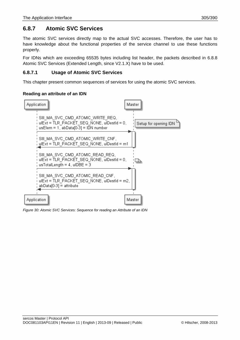
The Application Interface 305/390
sercos Master | Protocol API DOC081103API11EN | Revision 11 | English | 2013-09 | Released | Public © Hilscher, 2008-2013
6.8.7 Atomic SVC Services
The atomic SVC services directly map to the actual SVC accesses. Therefore, the user has to have knowledge about the functional properties of the service channel to use these functions properly.
For IDNs which are exceeding 65535 bytes including list header, the packets described in 6.8.8 Atomic SVC Services (Extended Length, since V2.1.X) have to be used.
6.8.7.1 Usage of Atomic SVC Services
This chapter present common sequences of services for using the atomic SVC services.
Reading an attribute of an IDN
Figure 30: Atomic SVC Services: Sequence for reading an Attribute of an IDN
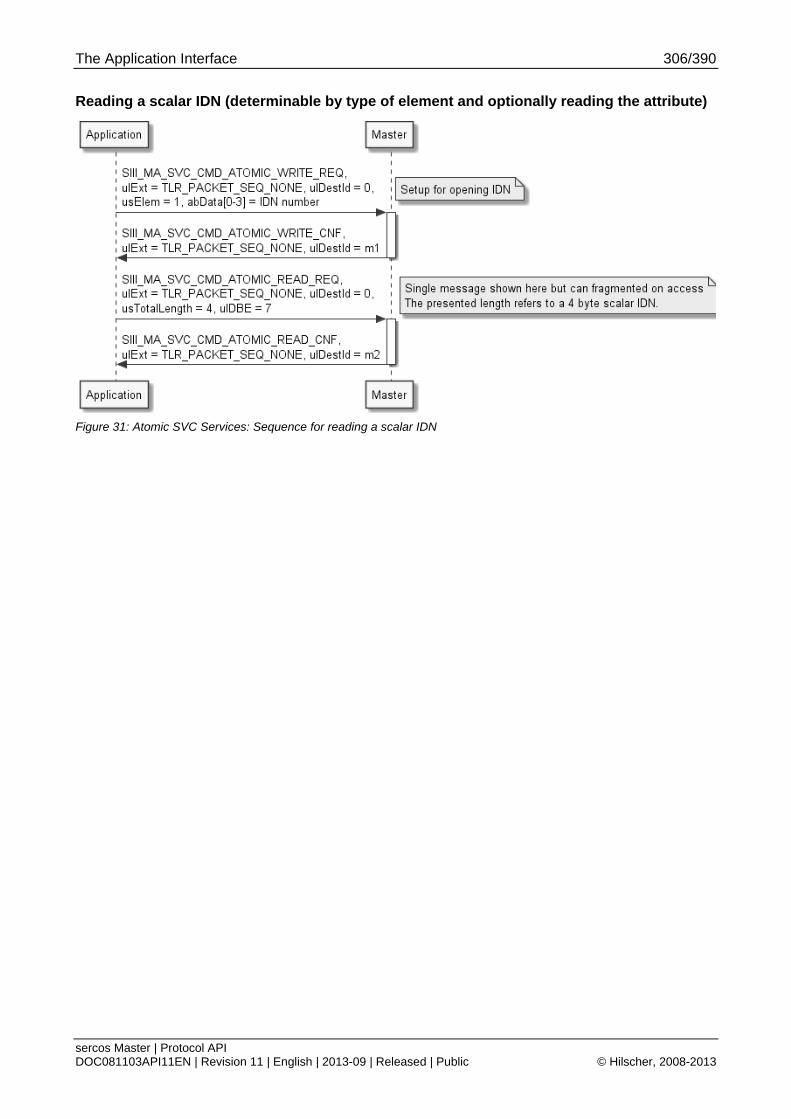
The Application Interface 306/390
sercos Master | Protocol API DOC081103API11EN | Revision 11 | English | 2013-09 | Released | Public © Hilscher, 2008-2013
Reading a scalar IDN (determinable by type of element and optionally reading the attribute)
Figure 31: Atomic SVC Services: Sequence for reading a scalar IDN
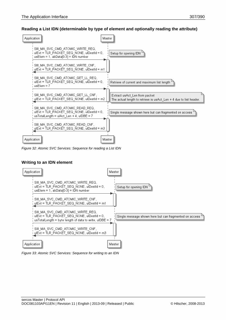
The Application Interface 307/390
sercos Master | Protocol API DOC081103API11EN | Revision 11 | English | 2013-09 | Released | Public © Hilscher, 2008-2013
Reading a List IDN (determinable by type of element and optionally reading the attribute)
Figure 32: Atomic SVC Services: Sequence for reading a List IDN
Writing to an IDN element
Figure 33: Atomic SVC Services: Sequence for writing to an IDN
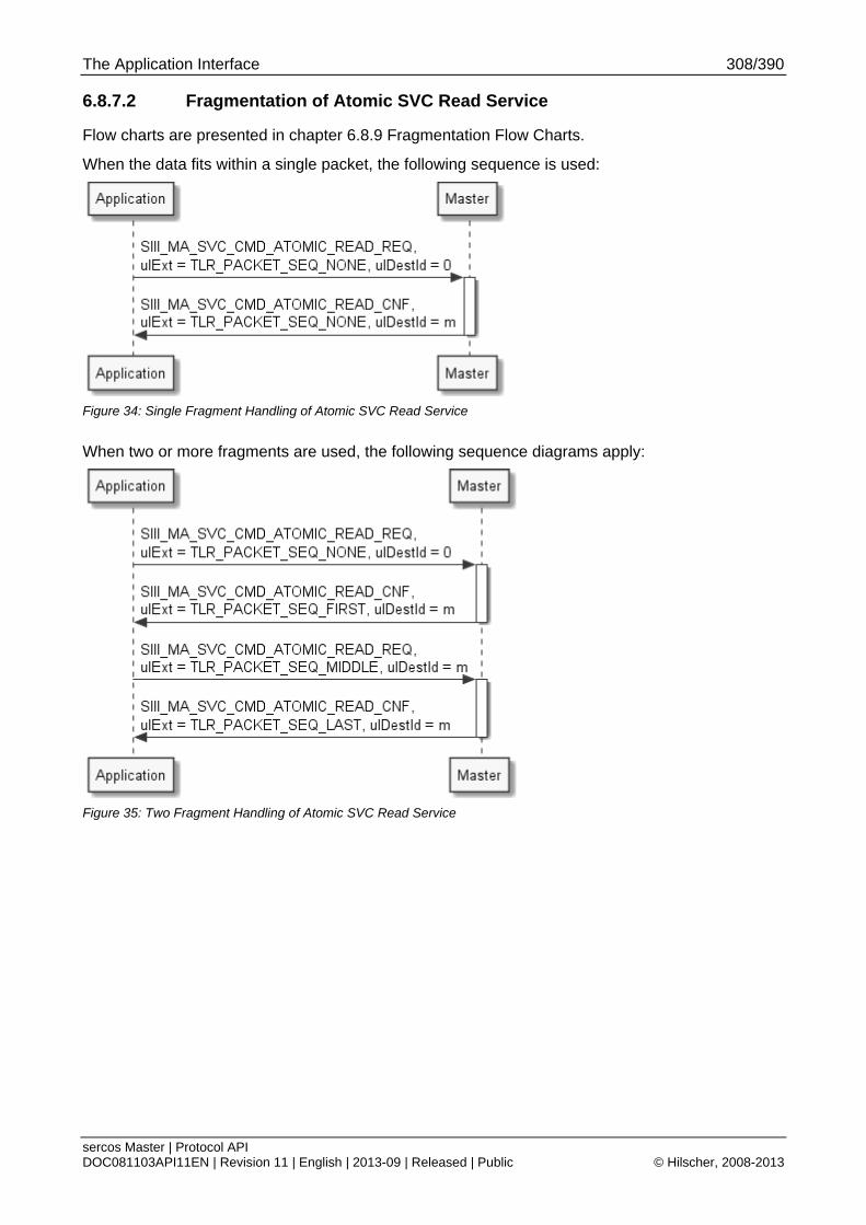
The Application Interface 308/390
sercos Master | Protocol API DOC081103API11EN | Revision 11 | English | 2013-09 | Released | Public © Hilscher, 2008-2013
6.8.7.2 Fragmentation of Atomic SVC Read Service
Flow charts are presented in chapter 6.8.9 Fragmentation Flow Charts.
When the data fits within a single packet, the following sequence is used:
Figure 34: Single Fragment Handling of Atomic SVC Read Service
When two or more fragments are used, the following sequence diagrams apply:
Figure 35: Two Fragment Handling of Atomic SVC Read Service

The Application Interface 309/390
sercos Master | Protocol API DOC081103API11EN | Revision 11 | English | 2013-09 | Released | Public © Hilscher, 2008-2013
Table 240: Multiple Fragment Handling of Atomic SVC Read Service

The Application Interface 310/390
sercos Master | Protocol API DOC081103API11EN | Revision 11 | English | 2013-09 | Released | Public © Hilscher, 2008-2013
6.8.7.3 Fragmentation of Atomic SVC Write Service
Flow charts are presented in chapter 6.8.9 Fragmentation Flow Charts.
When data fits into a single packet, the following sequence is used:
Figure 36: Single Fragment Handling of Atomic SVC Write Service
When two or more fragments are used, the following sequence diagrams apply:
Figure 37: Two Fragment Handling of Atomic SVC Write Service
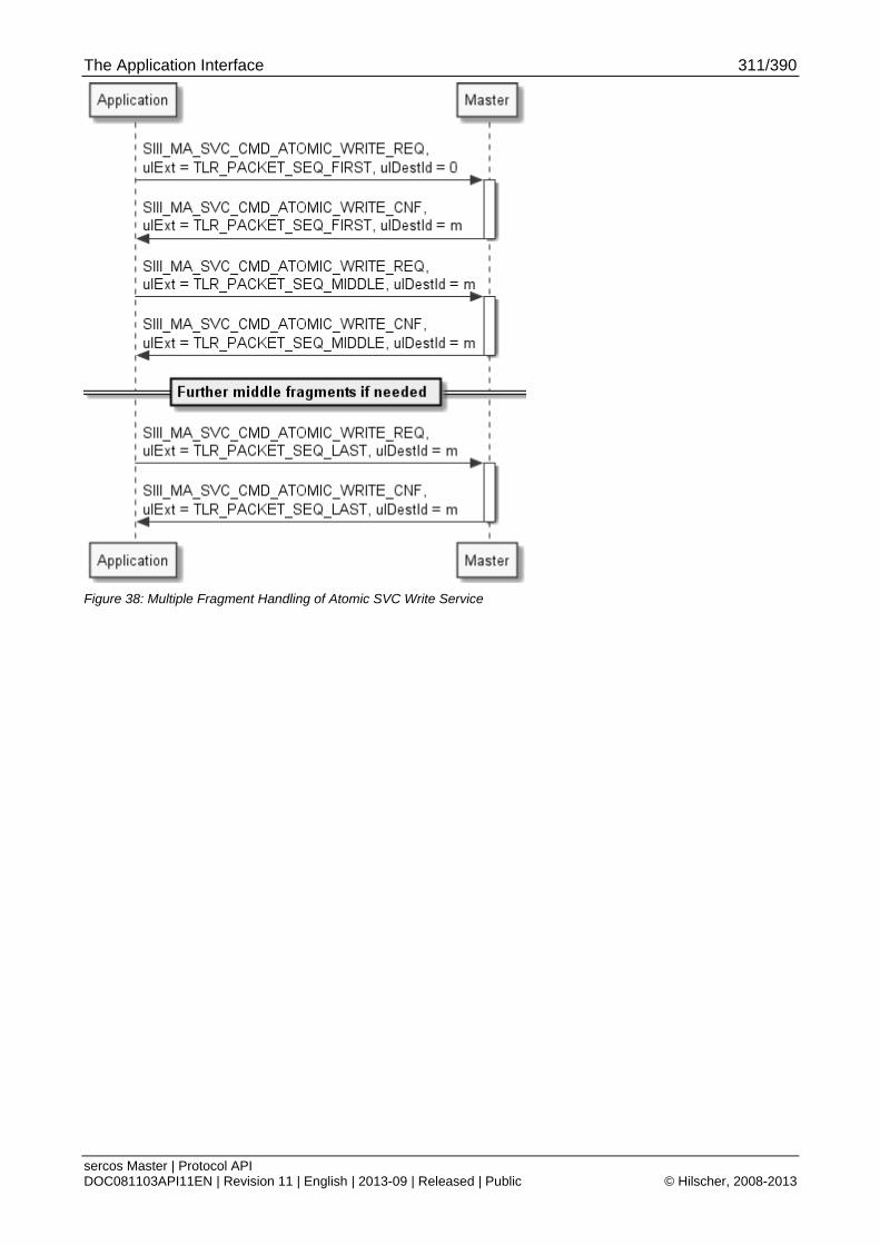
The Application Interface 311/390
sercos Master | Protocol API DOC081103API11EN | Revision 11 | English | 2013-09 | Released | Public © Hilscher, 2008-2013
Figure 38: Multiple Fragment Handling of Atomic SVC Write Service
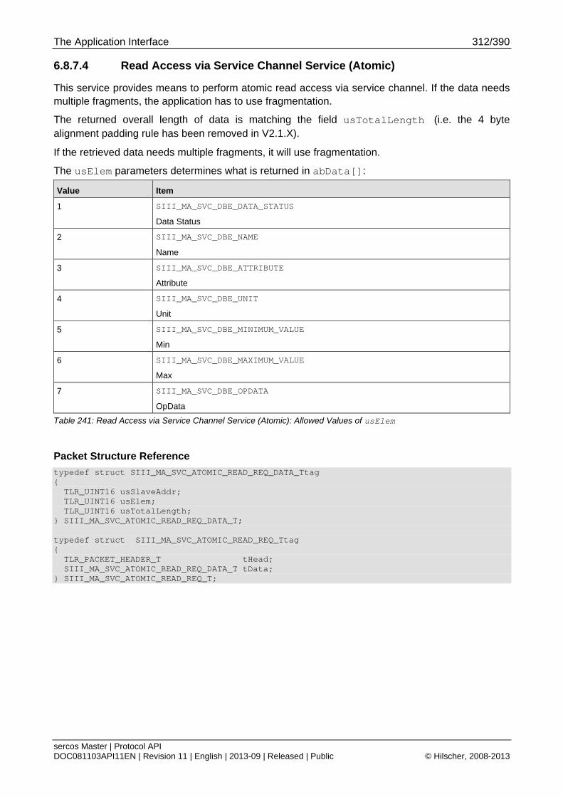
The Application Interface 312/390
sercos Master | Protocol API DOC081103API11EN | Revision 11 | English | 2013-09 | Released | Public © Hilscher, 2008-2013
6.8.7.4 Read Access via Service Channel Service (Atomic)
This service provides means to perform atomic read access via service channel. If the data needs multiple fragments, the application has to use fragmentation.
The returned overall length of data is matching the field usTotalLength (i.e. the 4 byte alignment padding rule has been removed in V2.1.X).
If the retrieved data needs multiple fragments, it will use fragmentation.
The usElem parameters determines what is returned in abData[]:
Value Item
1 SIII_MA_SVC_DBE_DATA_STATUS
Data Status
2 SIII_MA_SVC_DBE_NAME
Name
3 SIII_MA_SVC_DBE_ATTRIBUTE
Attribute
4 SIII_MA_SVC_DBE_UNIT
Unit
5 SIII_MA_SVC_DBE_MINIMUM_VALUE
Min
6 SIII_MA_SVC_DBE_MAXIMUM_VALUE
Max
7 SIII_MA_SVC_DBE_OPDATA
OpData
Table 241: Read Access via Service Channel Service (Atomic): Allowed Values of usElem
Packet Structure Reference
typedef struct SIII_MA_SVC_ATOMIC_READ_REQ_DATA_Ttag { TLR_UINT16 usSlaveAddr; TLR_UINT16 usElem; TLR_UINT16 usTotalLength; } SIII_MA_SVC_ATOMIC_READ_REQ_DATA_T; typedef struct SIII_MA_SVC_ATOMIC_READ_REQ_Ttag { TLR_PACKET_HEADER_T tHead; SIII_MA_SVC_ATOMIC_READ_REQ_DATA_T tData; } SIII_MA_SVC_ATOMIC_READ_REQ_T;
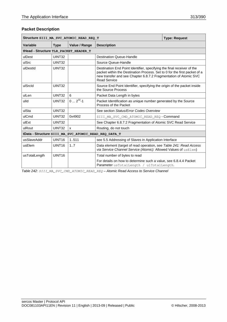
The Application Interface 313/390
sercos Master | Protocol API DOC081103API11EN | Revision 11 | English | 2013-09 | Released | Public © Hilscher, 2008-2013
Packet Description
Structure SIII_MA_SVC_ATOMIC_READ_REQ_T Type: Request
Variable Type Value / Range Description
tHead - Structure TLR_PACKET_HEADER_T
ulDest UINT32 Destination Queue-Handle
ulSrc UINT32 Source Queue-Handle
ulDestId UINT32 Destination End Point Identifier, specifying the final receiver of the packet within the Destination Process. Set to 0 for the first packet of a new transfer and see Chapter 6.8.7.2 Fragmentation of Atomic SVC Read Service
ulSrcId UINT32 Source End Point Identifier, specifying the origin of the packet inside the Source Process
ulLen UINT32 6 Packet Data Length in bytes
ulId UINT32 0 ... 232-1 Packet Identification as unique number generated by the Source Process of the Packet
ulSta UINT32 See section Status/Error Codes Overview
ulCmd UINT32 0x4902 SIII_MA_SVC_CMD_ATOMIC_READ_REQ - Command
ulExt UINT32 See Chapter 6.8.7.2 Fragmentation of Atomic SVC Read Service
ulRout UINT32 x Routing, do not touch
tData - Structure SIII_MA_SVC_ATOMIC_READ_REQ_DATA_T
usSlaveAddr UINT16 1..511 see 5.5 Addressing of Slaves in Application Interface
usElem UINT16 1..7 Data element (target of read operation, see Table 241: Read Access via Service Channel Service (Atomic): Allowed Values of usElem)
usTotalLength UINT16 Total number of bytes to read
For details on how to determine such a value, see 6.8.4.4 Packet Parameter usTotalLength / ulTotalLength.
Table 242: SIII_MA_SVC_CMD_ATOMIC_READ_REQ – Atomic Read Access to Service Channel
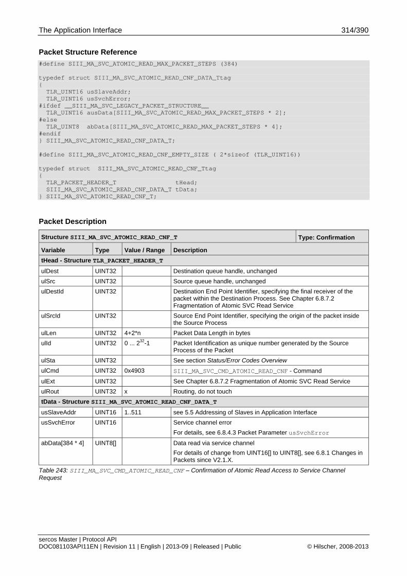
The Application Interface 314/390
sercos Master | Protocol API DOC081103API11EN | Revision 11 | English | 2013-09 | Released | Public © Hilscher, 2008-2013
Packet Structure Reference
#define SIII_MA_SVC_ATOMIC_READ_MAX_PACKET_STEPS (384) typedef struct SIII_MA_SVC_ATOMIC_READ_CNF_DATA_Ttag { TLR_UINT16 usSlaveAddr; TLR_UINT16 usSvchError; #ifdef __SIII_MA_SVC_LEGACY_PACKET_STRUCTURE__ TLR_UINT16 ausData[SIII_MA_SVC_ATOMIC_READ_MAX_PACKET_STEPS * 2]; #else TLR_UINT8 abData[SIII_MA_SVC_ATOMIC_READ_MAX_PACKET_STEPS * 4]; #endif } SIII_MA_SVC_ATOMIC_READ_CNF_DATA_T; #define SIII_MA_SVC_ATOMIC_READ_CNF_EMPTY_SIZE ( 2*sizeof (TLR_UINT16)) typedef struct SIII_MA_SVC_ATOMIC_READ_CNF_Ttag { TLR_PACKET_HEADER_T tHead; SIII_MA_SVC_ATOMIC_READ_CNF_DATA_T tData; } SIII_MA_SVC_ATOMIC_READ_CNF_T;
Packet Description
Structure SIII_MA_SVC_ATOMIC_READ_CNF_T Type: Confirmation
Variable Type Value / Range Description
tHead - Structure TLR_PACKET_HEADER_T
ulDest UINT32 Destination queue handle, unchanged
ulSrc UINT32 Source queue handle, unchanged
ulDestId UINT32 Destination End Point Identifier, specifying the final receiver of the packet within the Destination Process. See Chapter 6.8.7.2 Fragmentation of Atomic SVC Read Service
ulSrcId UINT32 Source End Point Identifier, specifying the origin of the packet inside the Source Process
ulLen UINT32 4+2*n Packet Data Length in bytes
ulId UINT32 0 ... 232-1 Packet Identification as unique number generated by the Source Process of the Packet
ulSta UINT32 See section Status/Error Codes Overview
ulCmd UINT32 0x4903 SIII_MA_SVC_CMD_ATOMIC_READ_CNF - Command
ulExt UINT32 See Chapter 6.8.7.2 Fragmentation of Atomic SVC Read Service
ulRout UINT32 x Routing, do not touch
tData - Structure SIII_MA_SVC_ATOMIC_READ_CNF_DATA_T
usSlaveAddr UINT16 1..511 see 5.5 Addressing of Slaves in Application Interface
usSvchError UINT16 Service channel error
For details, see 6.8.4.3 Packet Parameter usSvchError
abData[384 * 4] UINT8[] Data read via service channel
For details of change from UINT16[] to UINT8[], see 6.8.1 Changes in Packets since V2.1.X.
Table 243: SIII_MA_SVC_CMD_ATOMIC_READ_CNF – Confirmation of Atomic Read Access to Service Channel Request
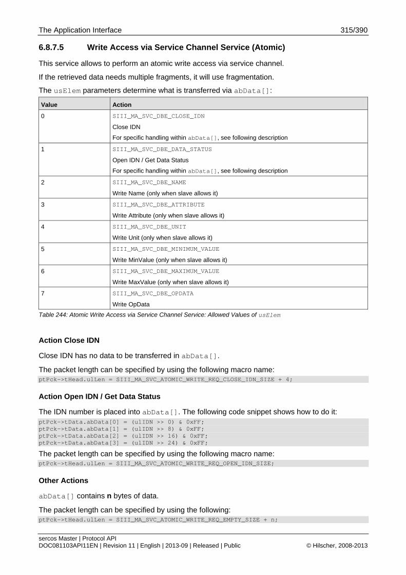
The Application Interface 315/390
sercos Master | Protocol API DOC081103API11EN | Revision 11 | English | 2013-09 | Released | Public © Hilscher, 2008-2013
6.8.7.5 Write Access via Service Channel Service (Atomic)
This service allows to perform an atomic write access via service channel.
If the retrieved data needs multiple fragments, it will use fragmentation.
The usElem parameters determine what is transferred via abData[]:
Value Action
0 SIII_MA_SVC_DBE_CLOSE_IDN
Close IDN
For specific handling within abData[], see following description
1 SIII_MA_SVC_DBE_DATA_STATUS
Open IDN / Get Data Status
For specific handling within abData[], see following description
2 SIII_MA_SVC_DBE_NAME
Write Name (only when slave allows it)
3 SIII_MA_SVC_DBE_ATTRIBUTE
Write Attribute (only when slave allows it)
4 SIII_MA_SVC_DBE_UNIT
Write Unit (only when slave allows it)
5 SIII_MA_SVC_DBE_MINIMUM_VALUE
Write MinValue (only when slave allows it)
6 SIII_MA_SVC_DBE_MAXIMUM_VALUE
Write MaxValue (only when slave allows it)
7 SIII_MA_SVC_DBE_OPDATA
Write OpData
Table 244: Atomic Write Access via Service Channel Service: Allowed Values of usElem
Action Close IDN
Close IDN has no data to be transferred in abData[].
The packet length can be specified by using the following macro name: ptPck->tHead.ulLen = SIII_MA_SVC_ATOMIC_WRITE_REQ_CLOSE_IDN_SIZE + 4;
Action Open IDN / Get Data Status
The IDN number is placed into abData[]. The following code snippet shows how to do it: ptPck->tData.abData[0] = (ulIDN >> 0) & 0xFF; ptPck->tData.abData[1] = (ulIDN >> 8) & 0xFF; ptPck->tData.abData[2] = (ulIDN >> 16) & 0xFF; ptPck->tData.abData[3] = (ulIDN >> 24) & 0xFF;
The packet length can be specified by using the following macro name: ptPck->tHead.ulLen = SIII_MA_SVC_ATOMIC_WRITE_REQ_OPEN_IDN_SIZE;
Other Actions
abData[] contains n bytes of data.
The packet length can be specified by using the following: ptPck->tHead.ulLen = SIII_MA_SVC_ATOMIC_WRITE_REQ_EMPTY_SIZE + n;
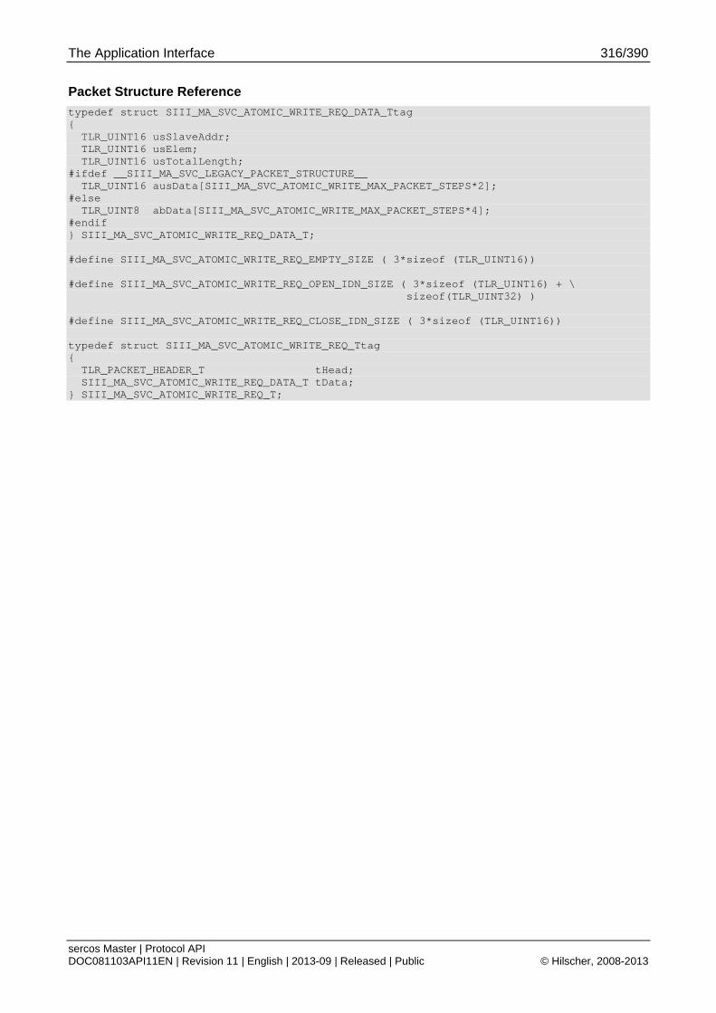
The Application Interface 316/390
sercos Master | Protocol API DOC081103API11EN | Revision 11 | English | 2013-09 | Released | Public © Hilscher, 2008-2013
Packet Structure Reference
typedef struct SIII_MA_SVC_ATOMIC_WRITE_REQ_DATA_Ttag { TLR_UINT16 usSlaveAddr; TLR_UINT16 usElem; TLR_UINT16 usTotalLength; #ifdef __SIII_MA_SVC_LEGACY_PACKET_STRUCTURE__ TLR_UINT16 ausData[SIII_MA_SVC_ATOMIC_WRITE_MAX_PACKET_STEPS*2]; #else TLR_UINT8 abData[SIII_MA_SVC_ATOMIC_WRITE_MAX_PACKET_STEPS*4]; #endif } SIII_MA_SVC_ATOMIC_WRITE_REQ_DATA_T; #define SIII_MA_SVC_ATOMIC_WRITE_REQ_EMPTY_SIZE ( 3*sizeof (TLR_UINT16)) #define SIII_MA_SVC_ATOMIC_WRITE_REQ_OPEN_IDN_SIZE ( 3*sizeof (TLR_UINT16) + \ sizeof(TLR_UINT32) ) #define SIII_MA_SVC_ATOMIC_WRITE_REQ_CLOSE_IDN_SIZE ( 3*sizeof (TLR_UINT16)) typedef struct SIII_MA_SVC_ATOMIC_WRITE_REQ_Ttag { TLR_PACKET_HEADER_T tHead; SIII_MA_SVC_ATOMIC_WRITE_REQ_DATA_T tData; } SIII_MA_SVC_ATOMIC_WRITE_REQ_T;
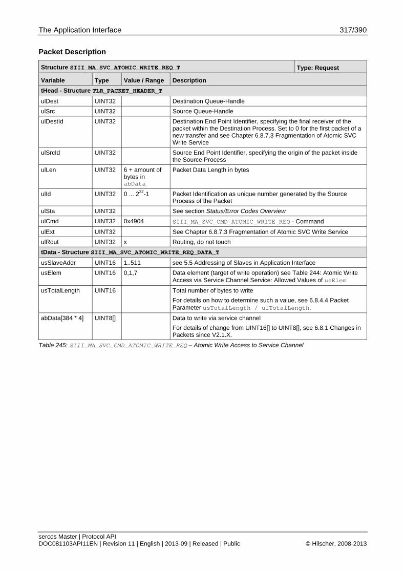
The Application Interface 317/390
sercos Master | Protocol API DOC081103API11EN | Revision 11 | English | 2013-09 | Released | Public © Hilscher, 2008-2013
Packet Description
Structure SIII_MA_SVC_ATOMIC_WRITE_REQ_T Type: Request
Variable Type Value / Range Description
tHead - Structure TLR_PACKET_HEADER_T
ulDest UINT32 Destination Queue-Handle
ulSrc UINT32 Source Queue-Handle
ulDestId UINT32 Destination End Point Identifier, specifying the final receiver of the packet within the Destination Process. Set to 0 for the first packet of a new transfer and see Chapter 6.8.7.3 Fragmentation of Atomic SVC Write Service
ulSrcId UINT32 Source End Point Identifier, specifying the origin of the packet inside the Source Process
ulLen UINT32 6 + amount of bytes in abData
Packet Data Length in bytes
ulId UINT32 0 ... 232-1 Packet Identification as unique number generated by the Source Process of the Packet
ulSta UINT32 See section Status/Error Codes Overview
ulCmd UINT32 0x4904 SIII_MA_SVC_CMD_ATOMIC_WRITE_REQ - Command
ulExt UINT32 See Chapter 6.8.7.3 Fragmentation of Atomic SVC Write Service
ulRout UINT32 x Routing, do not touch
tData - Structure SIII_MA_SVC_ATOMIC_WRITE_REQ_DATA_T
usSlaveAddr UINT16 1..511 see 5.5 Addressing of Slaves in Application Interface
usElem UINT16 0,1,7 Data element (target of write operation) see Table 244: Atomic Write Access via Service Channel Service: Allowed Values of usElem
usTotalLength UINT16 Total number of bytes to write
For details on how to determine such a value, see 6.8.4.4 Packet Parameter usTotalLength / ulTotalLength.
abData[384 * 4] UINT8[] Data to write via service channel
For details of change from UINT16[] to UINT8[], see 6.8.1 Changes in Packets since V2.1.X.
Table 245: SIII_MA_SVC_CMD_ATOMIC_WRITE_REQ – Atomic Write Access to Service Channel
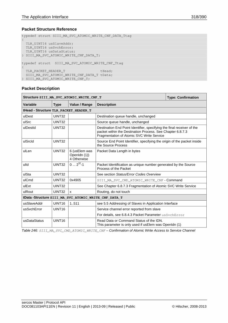
The Application Interface 318/390
sercos Master | Protocol API DOC081103API11EN | Revision 11 | English | 2013-09 | Released | Public © Hilscher, 2008-2013
Packet Structure Reference
typedef struct SIII_MA_SVC_ATOMIC_WRITE_CNF_DATA_Ttag { TLR_UINT16 usSlaveAddr; TLR_UINT16 usSvchError; TLR_UINT16 usDataStatus; } SIII_MA_SVC_ATOMIC_WRITE_CNF_DATA_T; typedef struct SIII_MA_SVC_ATOMIC_WRITE_CNF_Ttag { TLR_PACKET_HEADER_T tHead; SIII_MA_SVC_ATOMIC_WRITE_CNF_DATA_T tData; } SIII_MA_SVC_ATOMIC_WRITE_CNF_T;
Packet Description
Structure SIII_MA_SVC_ATOMIC_WRITE_CNF_T Type: Confirmation
Variable Type Value / Range Description
tHead - Structure TLR_PACKET_HEADER_T
ulDest UINT32 Destination queue handle, unchanged
ulSrc UINT32 Source queue handle, unchanged
ulDestId UINT32 Destination End Point Identifier, specifying the final receiver of the packet within the Destination Process. See Chapter 6.8.7.3 Fragmentation of Atomic SVC Write Service
ulSrcId UINT32 Source End Point Identifier, specifying the origin of the packet inside the Source Process
ulLen UINT32 6 (usElem was OpenIdn (1)) 4 Otherwise
Packet Data Length in bytes
ulId UINT32 0 ... 232-1 Packet Identification as unique number generated by the Source Process of the Packet
ulSta UINT32 See section Status/Error Codes Overview
ulCmd UINT32 0x4905 SIII_MA_SVC_CMD_ATOMIC_WRITE_CNF - Command
ulExt UINT32 See Chapter 6.8.7.3 Fragmentation of Atomic SVC Write Service
ulRout UINT32 x Routing, do not touch
tData -Structure SIII_MA_SVC_ATOMIC_WRITE_CNF_DATA_T
usSlaveAddr UINT16 1..511 see 5.5 Addressing of Slaves in Application Interface
usSvchError UINT16 Service channel error reported from slave
For details, see 6.8.4.3 Packet Parameter usSvchError
usDataStatus UINT16 Read Data or Command Status of the IDN. This parameter is only used if usElem was OpenIdn (1)
Table 246: SIII_MA_SVC_CMD_ATOMIC_WRITE_CNF – Confirmation of Atomic Write Access to Service Channel

The Application Interface 319/390
sercos Master | Protocol API DOC081103API11EN | Revision 11 | English | 2013-09 | Released | Public © Hilscher, 2008-2013
6.8.7.6 Get List Length Service (Atomic)
This service is used to retrieve the list length of a data block element of an IDN. Any list IDN data element has a four byte header which is containing that information.
The following data block elements can be selected with usElem:
Value Item
2 SIII_MA_SVC_DBE_NAME
Name
always a list
4 SIII_MA_SVC_DBE_UNIT
Unit
always a list
7 SIII_MA_SVC_DBE_OPDATA
OpData
see following text
Table 247: Get List Length Service (Atomic): Allowed Values of usElem
Note: When data block element 7 (OpData) is selected, the data can be either a scalar or a list. If the accessed data block element is a scalar, the request will return improper data.
Packet Structure Reference
typedef struct SIII_MA_SVC_ATOMIC_GET_LL_REQ_DATA_Ttag { TLR_UINT16 usSlaveAddr; TLR_UINT16 usElem; } SIII_MA_SVC_ATOMIC_GET_LL_REQ_DATA_T; typedef struct SIII_MA_SVC_ATOMIC_GET_LL_REQ_Ttag { TLR_PACKET_HEADER_T tHead; SIII_MA_SVC_ATOMIC_GET_LL_REQ_DATA_T tData; } SIII_MA_SVC_ATOMIC_GET_LL_REQ_T;
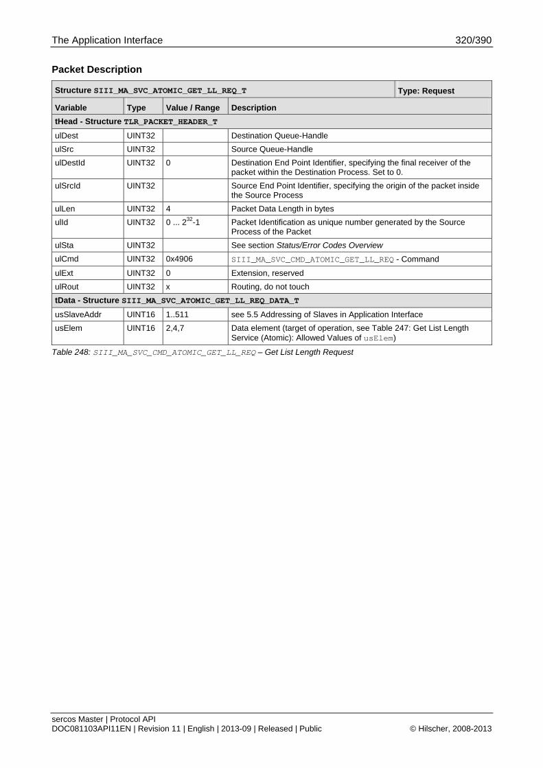
The Application Interface 320/390
sercos Master | Protocol API DOC081103API11EN | Revision 11 | English | 2013-09 | Released | Public © Hilscher, 2008-2013
Packet Description
Structure SIII_MA_SVC_ATOMIC_GET_LL_REQ_T Type: Request
Variable Type Value / Range Description
tHead - Structure TLR_PACKET_HEADER_T
ulDest UINT32 Destination Queue-Handle
ulSrc UINT32 Source Queue-Handle
ulDestId UINT32 0 Destination End Point Identifier, specifying the final receiver of the packet within the Destination Process. Set to 0.
ulSrcId UINT32 Source End Point Identifier, specifying the origin of the packet inside the Source Process
ulLen UINT32 4 Packet Data Length in bytes
ulId UINT32 0 ... 232-1 Packet Identification as unique number generated by the Source Process of the Packet
ulSta UINT32 See section Status/Error Codes Overview
ulCmd UINT32 0x4906 SIII_MA_SVC_CMD_ATOMIC_GET_LL_REQ - Command
ulExt UINT32 0 Extension, reserved
ulRout UINT32 x Routing, do not touch
tData - Structure SIII_MA_SVC_ATOMIC_GET_LL_REQ_DATA_T
usSlaveAddr UINT16 1..511 see 5.5 Addressing of Slaves in Application Interface
usElem UINT16 2,4,7 Data element (target of operation, see Table 247: Get List Length Service (Atomic): Allowed Values of usElem)
Table 248: SIII_MA_SVC_CMD_ATOMIC_GET_LL_REQ – Get List Length Request
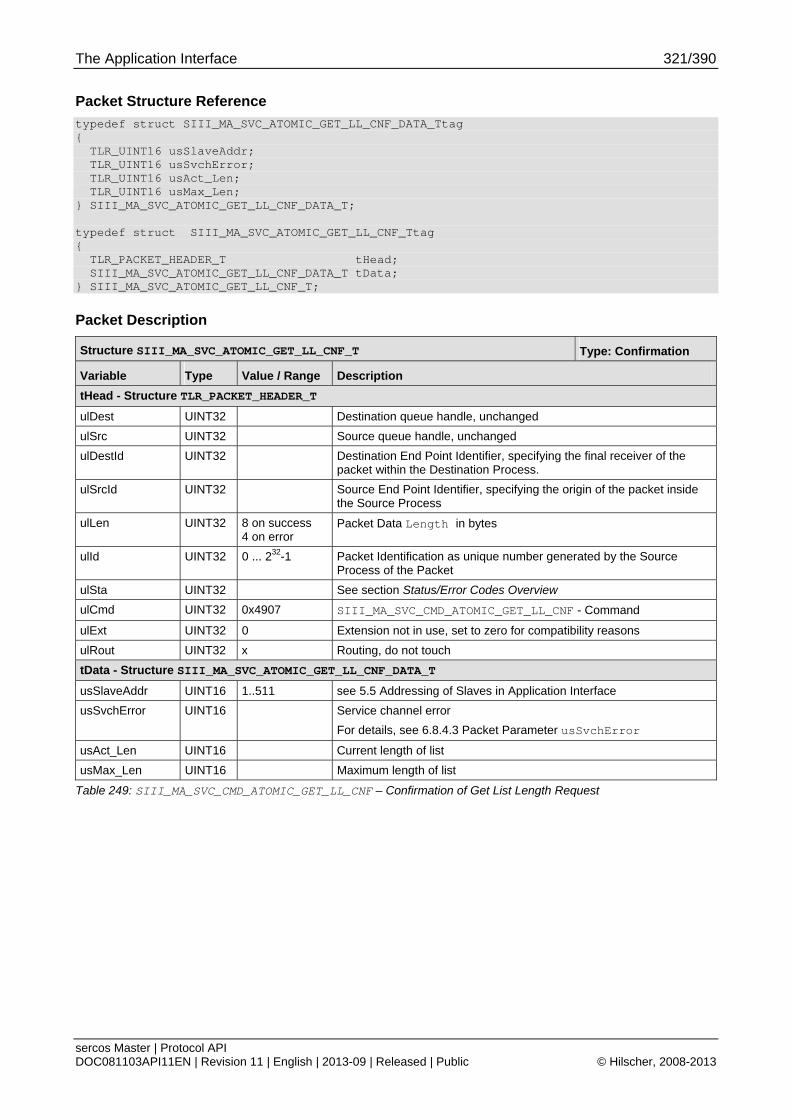
The Application Interface 321/390
sercos Master | Protocol API DOC081103API11EN | Revision 11 | English | 2013-09 | Released | Public © Hilscher, 2008-2013
Packet Structure Reference
typedef struct SIII_MA_SVC_ATOMIC_GET_LL_CNF_DATA_Ttag { TLR_UINT16 usSlaveAddr; TLR_UINT16 usSvchError; TLR_UINT16 usAct_Len; TLR_UINT16 usMax_Len; } SIII_MA_SVC_ATOMIC_GET_LL_CNF_DATA_T; typedef struct SIII_MA_SVC_ATOMIC_GET_LL_CNF_Ttag { TLR_PACKET_HEADER_T tHead; SIII_MA_SVC_ATOMIC_GET_LL_CNF_DATA_T tData; } SIII_MA_SVC_ATOMIC_GET_LL_CNF_T;
Packet Description
Structure SIII_MA_SVC_ATOMIC_GET_LL_CNF_T Type: Confirmation
Variable Type Value / Range Description
tHead - Structure TLR_PACKET_HEADER_T
ulDest UINT32 Destination queue handle, unchanged
ulSrc UINT32 Source queue handle, unchanged
ulDestId UINT32 Destination End Point Identifier, specifying the final receiver of the packet within the Destination Process.
ulSrcId UINT32 Source End Point Identifier, specifying the origin of the packet inside the Source Process
ulLen UINT32 8 on success 4 on error
Packet Data Length in bytes
ulId UINT32 0 ... 232-1 Packet Identification as unique number generated by the Source Process of the Packet
ulSta UINT32 See section Status/Error Codes Overview
ulCmd UINT32 0x4907 SIII_MA_SVC_CMD_ATOMIC_GET_LL_CNF - Command
ulExt UINT32 0 Extension not in use, set to zero for compatibility reasons
ulRout UINT32 x Routing, do not touch
tData - Structure SIII_MA_SVC_ATOMIC_GET_LL_CNF_DATA_T
usSlaveAddr UINT16 1..511 see 5.5 Addressing of Slaves in Application Interface
usSvchError UINT16 Service channel error
For details, see 6.8.4.3 Packet Parameter usSvchError
usAct_Len UINT16 Current length of list
usMax_Len UINT16 Maximum length of list
Table 249: SIII_MA_SVC_CMD_ATOMIC_GET_LL_CNF – Confirmation of Get List Length Request
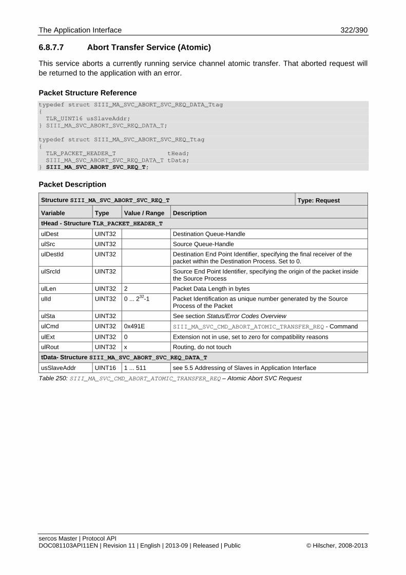
The Application Interface 322/390
sercos Master | Protocol API DOC081103API11EN | Revision 11 | English | 2013-09 | Released | Public © Hilscher, 2008-2013
6.8.7.7 Abort Transfer Service (Atomic)
This service aborts a currently running service channel atomic transfer. That aborted request will be returned to the application with an error.
Packet Structure Reference
typedef struct SIII_MA_SVC_ABORT_SVC_REQ_DATA_Ttag { TLR_UINT16 usSlaveAddr;
} SIII_MA_SVC_ABORT_SVC_REQ_DATA_T; typedef struct SIII_MA_SVC_ABORT_SVC_REQ_Ttag { TLR_PACKET_HEADER_T tHead; SIII_MA_SVC_ABORT_SVC_REQ_DATA_T tData;
} SIII_MA_SVC_ABORT_SVC_REQ_T;
Packet Description
Structure SIII_MA_SVC_ABORT_SVC_REQ_T Type: Request
Variable Type Value / Range Description
tHead - Structure TLR_PACKET_HEADER_T
ulDest UINT32 Destination Queue-Handle
ulSrc UINT32 Source Queue-Handle
ulDestId UINT32 Destination End Point Identifier, specifying the final receiver of the packet within the Destination Process. Set to 0.
ulSrcId UINT32 Source End Point Identifier, specifying the origin of the packet inside the Source Process
ulLen UINT32 2 Packet Data Length in bytes
ulId UINT32 0 ... 232-1 Packet Identification as unique number generated by the Source Process of the Packet
ulSta UINT32 See section Status/Error Codes Overview
ulCmd UINT32 0x491E SIII_MA_SVC_CMD_ABORT_ATOMIC_TRANSFER_REQ - Command
ulExt UINT32 0 Extension not in use, set to zero for compatibility reasons
ulRout UINT32 x Routing, do not touch
tData- Structure SIII_MA_SVC_ABORT_SVC_REQ_DATA_T
usSlaveAddr UINT16 1 ... 511 see 5.5 Addressing of Slaves in Application Interface
Table 250: SIII_MA_SVC_CMD_ABORT_ATOMIC_TRANSFER_REQ – Atomic Abort SVC Request
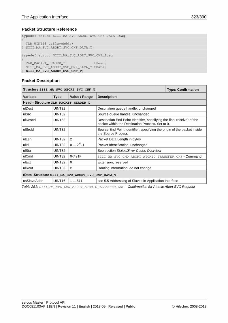
The Application Interface 323/390
sercos Master | Protocol API DOC081103API11EN | Revision 11 | English | 2013-09 | Released | Public © Hilscher, 2008-2013
Packet Structure Reference
typedef struct SIII_MA_SVC_ABORT_SVC_CNF_DATA_Ttag { TLR_UINT16 usSlaveAddr;
} SIII_MA_SVC_ABORT_SVC_CNF_DATA_T; typedef struct SIII_MA_SVC_AORT_SVC_CNF_Ttag { TLR_PACKET_HEADER_T tHead; SIII_MA_SVC_ABORT_SVC_CNF_DATA_T tData;
} SIII_MA_SVC_ABORT_SVC_CNF_T;
Packet Description
Structure SIII_MA_SVC_ABORT_SVC_CNF_T Type: Confirmation
Variable Type Value / Range Description
Head - Structure TLR_PACKET_HEADER_T
ulDest UINT32 Destination queue handle, unchanged
ulSrc UINT32 Source queue handle, unchanged
ulDestId UINT32 Destination End Point Identifier, specifying the final receiver of the packet within the Destination Process. Set to 0.
ulSrcId UINT32 Source End Point Identifier, specifying the origin of the packet inside the Source Process
ulLen UINT32 2 Packet Data Length in bytes
ulId UINT32 0 ... 232-1 Packet Identification, unchanged
ulSta UINT32 See section Status/Error Codes Overview
ulCmd UINT32 0x491F SIII_MA_SVC_CMD_ABORT_ATOMIC_TRANSFER_CNF - Command
ulExt UINT32 0 Extension, reserved
ulRout UINT32 x Routing information, do not change
tData -Structure SIII_MA_SVC_ABORT_SVC_CNF_DATA_T
usSlaveAddr UINT16 1 ... 511 see 5.5 Addressing of Slaves in Application Interface
Table 251: SIII_MA_SVC_CMD_ABORT_ATOMIC_TRANSFER_CNF – Confirmation for Atomic Abort SVC Request
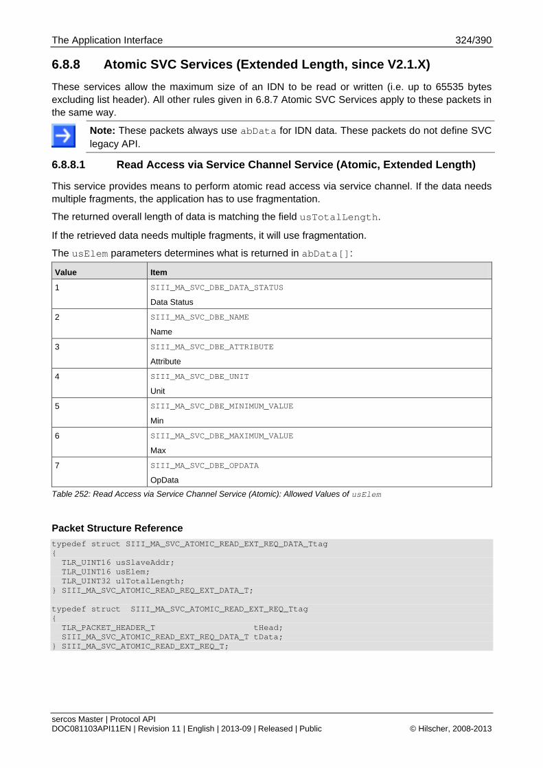
The Application Interface 324/390
sercos Master | Protocol API DOC081103API11EN | Revision 11 | English | 2013-09 | Released | Public © Hilscher, 2008-2013
6.8.8 Atomic SVC Services (Extended Length, since V2.1.X)
These services allow the maximum size of an IDN to be read or written (i.e. up to 65535 bytes excluding list header). All other rules given in 6.8.7 Atomic SVC Services apply to these packets in the same way.
Note: These packets always use abData for IDN data. These packets do not define SVC legacy API.
6.8.8.1 Read Access via Service Channel Service (Atomic, Extended Length)
This service provides means to perform atomic read access via service channel. If the data needs multiple fragments, the application has to use fragmentation.
The returned overall length of data is matching the field usTotalLength.
If the retrieved data needs multiple fragments, it will use fragmentation.
The usElem parameters determines what is returned in abData[]:
Value Item
1 SIII_MA_SVC_DBE_DATA_STATUS
Data Status
2 SIII_MA_SVC_DBE_NAME
Name
3 SIII_MA_SVC_DBE_ATTRIBUTE
Attribute
4 SIII_MA_SVC_DBE_UNIT
Unit
5 SIII_MA_SVC_DBE_MINIMUM_VALUE
Min
6 SIII_MA_SVC_DBE_MAXIMUM_VALUE
Max
7 SIII_MA_SVC_DBE_OPDATA
OpData
Table 252: Read Access via Service Channel Service (Atomic): Allowed Values of usElem
Packet Structure Reference
typedef struct SIII_MA_SVC_ATOMIC_READ_EXT_REQ_DATA_Ttag { TLR_UINT16 usSlaveAddr; TLR_UINT16 usElem; TLR_UINT32 ulTotalLength; } SIII_MA_SVC_ATOMIC_READ_REQ_EXT_DATA_T; typedef struct SIII_MA_SVC_ATOMIC_READ_EXT_REQ_Ttag { TLR_PACKET_HEADER_T tHead; SIII_MA_SVC_ATOMIC_READ_EXT_REQ_DATA_T tData; } SIII_MA_SVC_ATOMIC_READ_EXT_REQ_T;
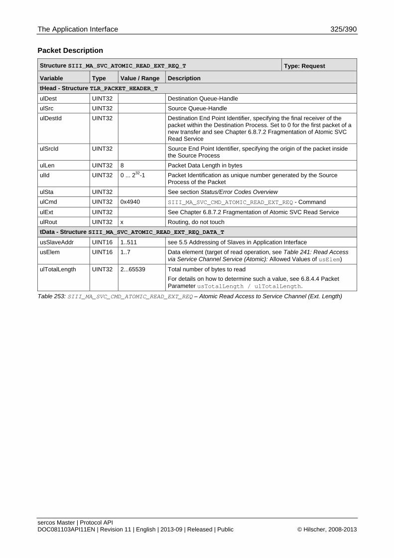
The Application Interface 325/390
sercos Master | Protocol API DOC081103API11EN | Revision 11 | English | 2013-09 | Released | Public © Hilscher, 2008-2013
Packet Description
Structure SIII_MA_SVC_ATOMIC_READ_EXT_REQ_T Type: Request
Variable Type Value / Range Description
tHead - Structure TLR_PACKET_HEADER_T
ulDest UINT32 Destination Queue-Handle
ulSrc UINT32 Source Queue-Handle
ulDestId UINT32 Destination End Point Identifier, specifying the final receiver of the packet within the Destination Process. Set to 0 for the first packet of a new transfer and see Chapter 6.8.7.2 Fragmentation of Atomic SVC Read Service
ulSrcId UINT32 Source End Point Identifier, specifying the origin of the packet inside the Source Process
ulLen UINT32 8 Packet Data Length in bytes
ulId UINT32 0 ... 232-1 Packet Identification as unique number generated by the Source Process of the Packet
ulSta UINT32 See section Status/Error Codes Overview
ulCmd UINT32 0x4940 SIII_MA_SVC_CMD_ATOMIC_READ_EXT_REQ - Command
ulExt UINT32 See Chapter 6.8.7.2 Fragmentation of Atomic SVC Read Service
ulRout UINT32 x Routing, do not touch
tData - Structure SIII_MA_SVC_ATOMIC_READ_EXT_REQ_DATA_T
usSlaveAddr UINT16 1..511 see 5.5 Addressing of Slaves in Application Interface
usElem UINT16 1..7 Data element (target of read operation, see Table 241: Read Access via Service Channel Service (Atomic): Allowed Values of usElem)
ulTotalLength UINT32 2...65539 Total number of bytes to read
For details on how to determine such a value, see 6.8.4.4 Packet Parameter usTotalLength / ulTotalLength.
Table 253: SIII_MA_SVC_CMD_ATOMIC_READ_EXT_REQ – Atomic Read Access to Service Channel (Ext. Length)
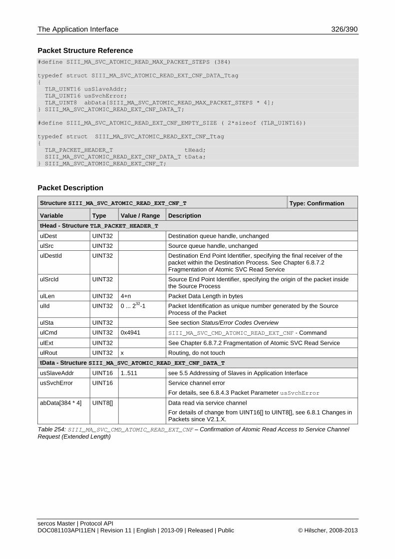
The Application Interface 326/390
sercos Master | Protocol API DOC081103API11EN | Revision 11 | English | 2013-09 | Released | Public © Hilscher, 2008-2013
Packet Structure Reference
#define SIII_MA_SVC_ATOMIC_READ_MAX_PACKET_STEPS (384) typedef struct SIII_MA_SVC_ATOMIC_READ_EXT_CNF_DATA_Ttag { TLR_UINT16 usSlaveAddr; TLR_UINT16 usSvchError; TLR_UINT8 abData[SIII_MA_SVC_ATOMIC_READ_MAX_PACKET_STEPS * 4]; } SIII_MA_SVC_ATOMIC_READ_EXT_CNF_DATA_T; #define SIII_MA_SVC_ATOMIC_READ_EXT_CNF_EMPTY_SIZE ( 2*sizeof (TLR_UINT16)) typedef struct SIII_MA_SVC_ATOMIC_READ_EXT_CNF_Ttag { TLR_PACKET_HEADER_T tHead; SIII_MA_SVC_ATOMIC_READ_EXT_CNF_DATA_T tData; } SIII_MA_SVC_ATOMIC_READ_EXT_CNF_T;
Packet Description
Structure SIII_MA_SVC_ATOMIC_READ_EXT_CNF_T Type: Confirmation
Variable Type Value / Range Description
tHead - Structure TLR_PACKET_HEADER_T
ulDest UINT32 Destination queue handle, unchanged
ulSrc UINT32 Source queue handle, unchanged
ulDestId UINT32 Destination End Point Identifier, specifying the final receiver of the packet within the Destination Process. See Chapter 6.8.7.2 Fragmentation of Atomic SVC Read Service
ulSrcId UINT32 Source End Point Identifier, specifying the origin of the packet inside the Source Process
ulLen UINT32 4+n Packet Data Length in bytes
ulId UINT32 0 ... 232-1 Packet Identification as unique number generated by the Source Process of the Packet
ulSta UINT32 See section Status/Error Codes Overview
ulCmd UINT32 0x4941 SIII_MA_SVC_CMD_ATOMIC_READ_EXT_CNF - Command
ulExt UINT32 See Chapter 6.8.7.2 Fragmentation of Atomic SVC Read Service
ulRout UINT32 x Routing, do not touch
tData - Structure SIII_MA_SVC_ATOMIC_READ_EXT_CNF_DATA_T
usSlaveAddr UINT16 1..511 see 5.5 Addressing of Slaves in Application Interface
usSvchError UINT16 Service channel error
For details, see 6.8.4.3 Packet Parameter usSvchError
abData[384 * 4] UINT8[] Data read via service channel
For details of change from UINT16[] to UINT8[], see 6.8.1 Changes in Packets since V2.1.X.
Table 254: SIII_MA_SVC_CMD_ATOMIC_READ_EXT_CNF – Confirmation of Atomic Read Access to Service Channel Request (Extended Length)
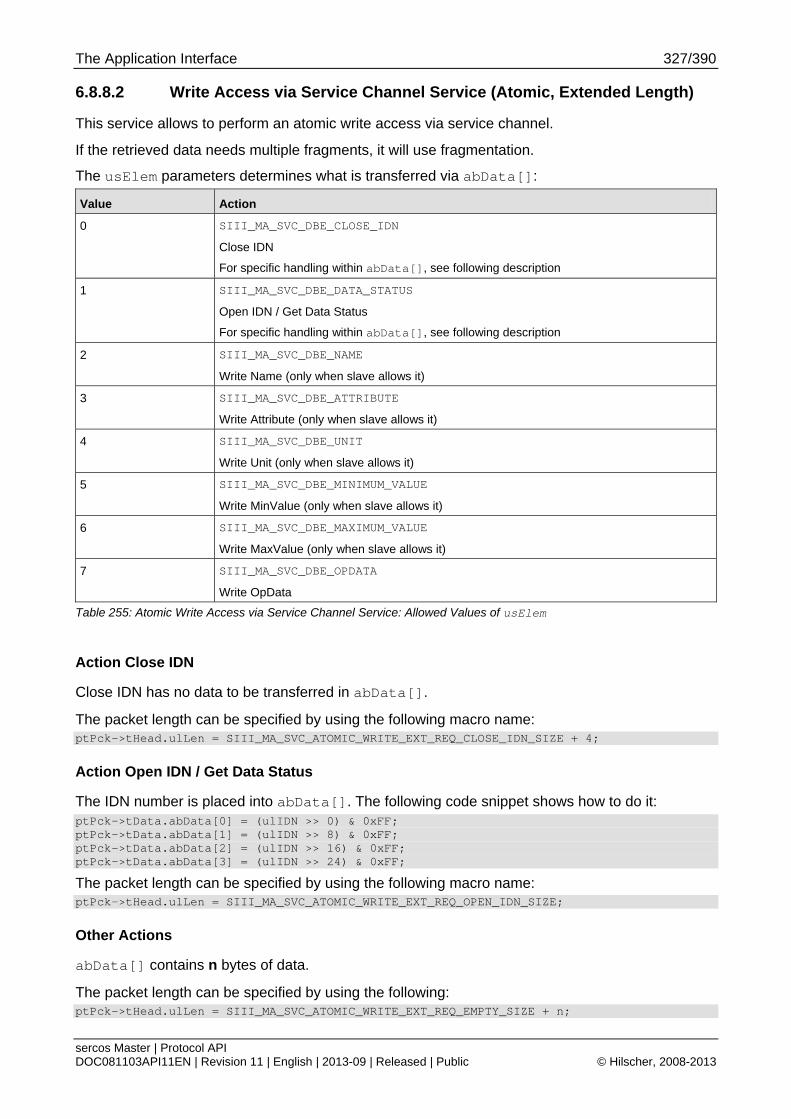
The Application Interface 327/390
sercos Master | Protocol API DOC081103API11EN | Revision 11 | English | 2013-09 | Released | Public © Hilscher, 2008-2013
6.8.8.2 Write Access via Service Channel Service (Atomic, Extended Length)
This service allows to perform an atomic write access via service channel.
If the retrieved data needs multiple fragments, it will use fragmentation.
The usElem parameters determines what is transferred via abData[]:
Value Action
0 SIII_MA_SVC_DBE_CLOSE_IDN
Close IDN
For specific handling within abData[], see following description
1 SIII_MA_SVC_DBE_DATA_STATUS
Open IDN / Get Data Status
For specific handling within abData[], see following description
2 SIII_MA_SVC_DBE_NAME
Write Name (only when slave allows it)
3 SIII_MA_SVC_DBE_ATTRIBUTE
Write Attribute (only when slave allows it)
4 SIII_MA_SVC_DBE_UNIT
Write Unit (only when slave allows it)
5 SIII_MA_SVC_DBE_MINIMUM_VALUE
Write MinValue (only when slave allows it)
6 SIII_MA_SVC_DBE_MAXIMUM_VALUE
Write MaxValue (only when slave allows it)
7 SIII_MA_SVC_DBE_OPDATA
Write OpData
Table 255: Atomic Write Access via Service Channel Service: Allowed Values of usElem
Action Close IDN
Close IDN has no data to be transferred in abData[].
The packet length can be specified by using the following macro name: ptPck->tHead.ulLen = SIII_MA_SVC_ATOMIC_WRITE_EXT_REQ_CLOSE_IDN_SIZE + 4;
Action Open IDN / Get Data Status
The IDN number is placed into abData[]. The following code snippet shows how to do it: ptPck->tData.abData[0] = (ulIDN >> 0) & 0xFF; ptPck->tData.abData[1] = (ulIDN >> 8) & 0xFF; ptPck->tData.abData[2] = (ulIDN >> 16) & 0xFF; ptPck->tData.abData[3] = (ulIDN >> 24) & 0xFF;
The packet length can be specified by using the following macro name: ptPck->tHead.ulLen = SIII_MA_SVC_ATOMIC_WRITE_EXT_REQ_OPEN_IDN_SIZE;
Other Actions
abData[] contains n bytes of data.
The packet length can be specified by using the following: ptPck->tHead.ulLen = SIII_MA_SVC_ATOMIC_WRITE_EXT_REQ_EMPTY_SIZE + n;
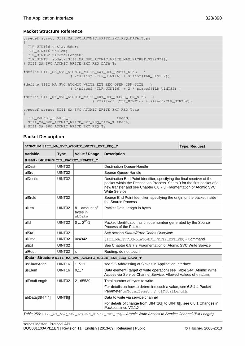
The Application Interface 328/390
sercos Master | Protocol API DOC081103API11EN | Revision 11 | English | 2013-09 | Released | Public © Hilscher, 2008-2013
Packet Structure Reference
typedef struct SIII_MA_SVC_ATOMIC_WRITE_EXT_REQ_DATA_Ttag { TLR_UINT16 usSlaveAddr; TLR_UINT16 usElem; TLR_UINT32 ulTotalLength; TLR_UINT8 abData[SIII_MA_SVC_ATOMIC_WRITE_MAX_PACKET_STEPS*4]; } SIII_MA_SVC_ATOMIC_WRITE_EXT_REQ_DATA_T; #define SIII_MA_SVC_ATOMIC_WRITE_EXT_REQ_EMPTY_SIZE \ ( 2*sizeof (TLR_UINT16) + sizeof(TLR_UINT32)) #define SIII_MA_SVC_ATOMIC_WRITE_EXT_REQ_OPEN_IDN_SIZE \ ( 2*sizeof (TLR_UINT16) + 2 * sizeof(TLR_UINT32) ) #define SIII_MA_SVC_ATOMIC_WRITE_EXT_REQ_CLOSE_IDN_SIZE \ ( 2*sizeof (TLR_UINT16) + sizeof(TLR_UINT32)) typedef struct SIII_MA_SVC_ATOMIC_WRITE_EXT_REQ_Ttag { TLR_PACKET_HEADER_T tHead; SIII_MA_SVC_ATOMIC_WRITE_EXT_REQ_DATA_T tData; } SIII_MA_SVC_ATOMIC_WRITE_EXT_REQ_T;
Packet Description
Structure SIII_MA_SVC_ATOMIC_WRITE_EXT_REQ_T Type: Request
Variable Type Value / Range Description
tHead - Structure TLR_PACKET_HEADER_T
ulDest UINT32 Destination Queue-Handle
ulSrc UINT32 Source Queue-Handle
ulDestId UINT32 Destination End Point Identifier, specifying the final receiver of the packet within the Destination Process. Set to 0 for the first packet of a new transfer and see Chapter 6.8.7.3 Fragmentation of Atomic SVC Write Service
ulSrcId UINT32 Source End Point Identifier, specifying the origin of the packet inside the Source Process
ulLen UINT32 8 + amount of bytes in abData
Packet Data Length in bytes
ulId UINT32 0 ... 232-1 Packet Identification as unique number generated by the Source Process of the Packet
ulSta UINT32 See section Status/Error Codes Overview
ulCmd UINT32 0x4942 SIII_MA_SVC_CMD_ATOMIC_WRITE_EXT_REQ - Command
ulExt UINT32 See Chapter 6.8.7.3 Fragmentation of Atomic SVC Write Service
ulRout UINT32 x Routing, do not touch
tData - Structure SIII_MA_SVC_ATOMIC_WRITE_EXT_REQ_DATA_T
usSlaveAddr UINT16 1..511 see 5.5 Addressing of Slaves in Application Interface
usElem UINT16 0,1,7 Data element (target of write operation) see Table 244: Atomic Write Access via Service Channel Service: Allowed Values of usElem
ulTotalLength UINT32 2...65539 Total number of bytes to write
For details on how to determine such a value, see 6.8.4.4 Packet Parameter usTotalLength / ulTotalLength.
abData[384 * 4] UINT8[] Data to write via service channel
For details of change from UINT16[] to UINT8[], see 6.8.1 Changes in Packets since V2.1.X.
Table 256: SIII_MA_SVC_CMD_ATOMIC_WRITE_EXT_REQ – Atomic Write Access to Service Channel (Ext Length)

The Application Interface 329/390
sercos Master | Protocol API DOC081103API11EN | Revision 11 | English | 2013-09 | Released | Public © Hilscher, 2008-2013
Packet Structure Reference
typedef struct SIII_MA_SVC_ATOMIC_WRITE_EXT_CNF_DATA_Ttag { TLR_UINT16 usSlaveAddr; TLR_UINT16 usSvchError; TLR_UINT16 usDataStatus; } SIII_MA_SVC_ATOMIC_WRITE_EXT_CNF_DATA_T; typedef struct SIII_MA_SVC_ATOMIC_WRITE_EXT_CNF_Ttag { TLR_PACKET_HEADER_T tHead; SIII_MA_SVC_ATOMIC_WRITE_EXT_CNF_DATA_T tData; } SIII_MA_SVC_ATOMIC_WRITE_EXT_CNF_T;
Packet Description
Structure SIII_MA_SVC_ATOMIC_WRITE_EXT_CNF_T Type: Confirmation
Variable Type Value / Range Description
tHead - Structure TLR_PACKET_HEADER_T
ulDest UINT32 Destination queue handle, unchanged
ulSrc UINT32 Source queue handle, unchanged
ulDestId UINT32 Destination End Point Identifier, specifying the final receiver of the packet within the Destination Process. See Chapter 6.8.7.3 Fragmentation of Atomic SVC Write Service
ulSrcId UINT32 Source End Point Identifier, specifying the origin of the packet inside the Source Process
ulLen UINT32 6 (usElem was OpenIdn (1)) 4 Otherwise
Packet Data Length in bytes
ulId UINT32 0 ... 232-1 Packet Identification as unique number generated by the Source Process of the Packet
ulSta UINT32 See section Status/Error Codes Overview
ulCmd UINT32 0x4943 SIII_MA_SVC_CMD_ATOMIC_WRITE_EXT_CNF - Command
ulExt UINT32 See Chapter 6.8.7.3 Fragmentation of Atomic SVC Write Service
ulRout UINT32 x Routing, do not touch
tData -Structure SIII_MA_SVC_ATOMIC_WRITE_EXT_CNF_DATA_T
usSlaveAddr UINT16 1..511 see 5.5 Addressing of Slaves in Application Interface
usSvchError UINT16 Service channel error reported from slave
For details, see 6.8.4.3 Packet Parameter usSvchError
usDataStatus UINT16 Read Data or Command Status of the IDN. This parameter is only used if usElem was OpenIdn (1)
Table 257: SIII_MA_SVC_CMD_ATOMIC_WRITE_EXT_CNF – Confirmation of Atomic Write Access to Service Channel (Ext Length)
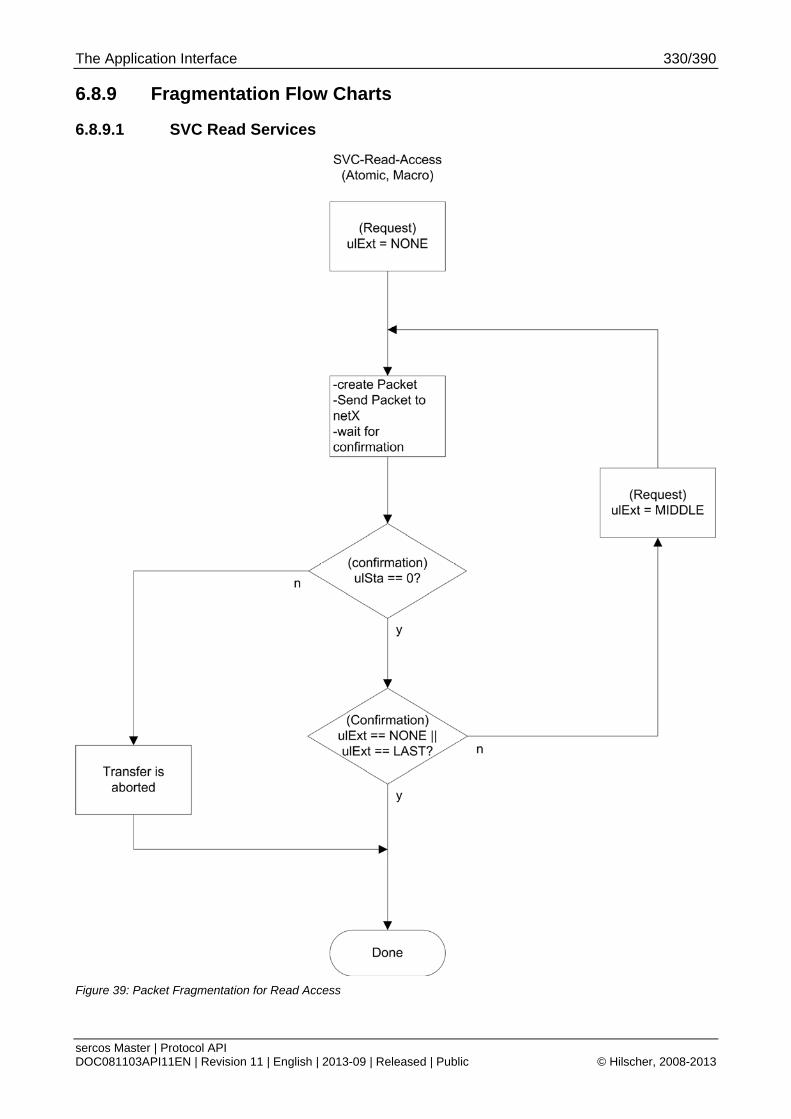
The Application Interface 330/390
sercos Master | Protocol API DOC081103API11EN | Revision 11 | English | 2013-09 | Released | Public © Hilscher, 2008-2013
6.8.9 Fragmentation Flow Charts
6.8.9.1 SVC Read Services
Figure 39: Packet Fragmentation for Read Access
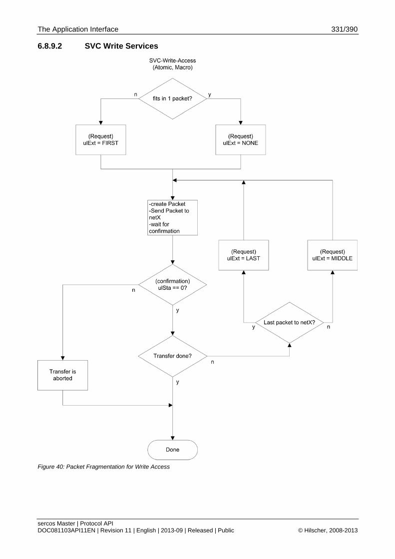
The Application Interface 331/390
sercos Master | Protocol API DOC081103API11EN | Revision 11 | English | 2013-09 | Released | Public © Hilscher, 2008-2013
6.8.9.2 SVC Write Services
Figure 40: Packet Fragmentation for Write Access

The Application Interface 332/390
sercos Master | Protocol API DOC081103API11EN | Revision 11 | English | 2013-09 | Released | Public © Hilscher, 2008-2013
6.9 Hot Plug (since V2.1.X)
6.9.1 Hot Plug Indication
The Hot Plug information part is embedded in the packet described in 6.4.2.2 Slaves Valid Indication Service (since V2.1.X). Therefore, its description will not be repeated here in detail.
When an error is shown within that indication, the error has to be acknowledgement before another slave will be handled through Hot Plug.
6.9.2 Hot Plug Error Acknowledgement Service
Packet Structure Reference
typedef struct SIII_MA_CP_ACKNOWLEDGE_HOT_PLUG_ERROR_REQ_Ttag { TLR_PACKET_HEADER_T tHead; } SIII_MA_CP_ACKNOWLEDGE_HOT_PLUG_ERROR_REQ_T;
Packet Description
Structure SIII_MA_CP_ACKNOWLEDGE_HOT_PLUG_ERROR_REQ_T Type: Request
Variable Type Value / Range Description
tHead - Structure TLR_PACKET_HEADER_T
ulDest UINT32 Destination Queue-Handle
ulSrc UINT32 Source Queue-Handle
ulDestId UINT32 Destination End Point Identifier, specifying the final receiver of the packet within the Destination Process. Set to 0 for the Initialization Packet
ulSrcId UINT32 Source End Point Identifier, specifying the origin of the packet inside the Source Process
ulLen UINT32 0 Packet Data Length in bytes
ulId UINT32 0 ... 232-1 Packet Identification as unique number generated by the Source Process of the Packet
ulSta UINT32 See section Status/Error Codes Overview
ulCmd UINT32 0x891C SIII_MA_CP_CMD_ACKNOWLEDGE_HOT_PLUG_ERROR_REQ - Command
ulExt UINT32 Extension, reserved
ulRout UINT32 x Routing, do not touch
Table 258: SIII_MA_CP_CMD_ACKNOWLEDGE_HOT_PLUG_ERROR_REQ – Acknowledge Hot Plug Error Request
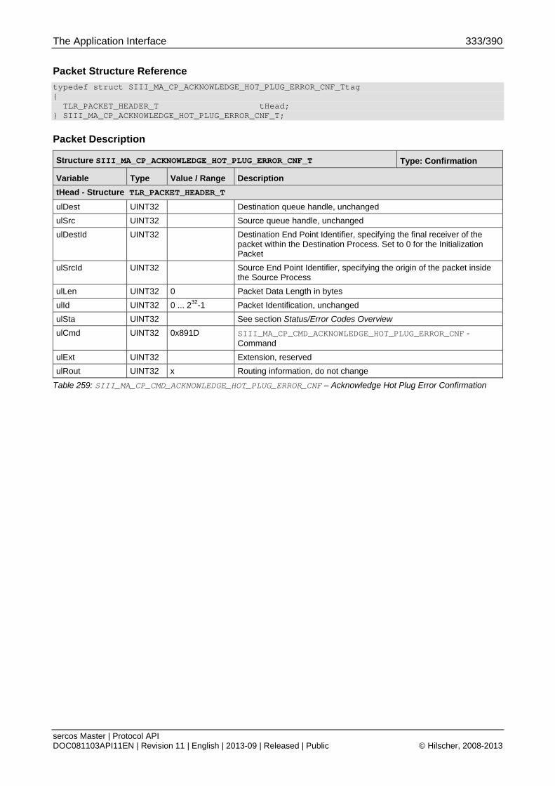
The Application Interface 333/390
sercos Master | Protocol API DOC081103API11EN | Revision 11 | English | 2013-09 | Released | Public © Hilscher, 2008-2013
Packet Structure Reference
typedef struct SIII_MA_CP_ACKNOWLEDGE_HOT_PLUG_ERROR_CNF_Ttag { TLR_PACKET_HEADER_T tHead; } SIII_MA_CP_ACKNOWLEDGE_HOT_PLUG_ERROR_CNF_T;
Packet Description
Structure SIII_MA_CP_ACKNOWLEDGE_HOT_PLUG_ERROR_CNF_T Type: Confirmation
Variable Type Value / Range Description
tHead - Structure TLR_PACKET_HEADER_T
ulDest UINT32 Destination queue handle, unchanged
ulSrc UINT32 Source queue handle, unchanged
ulDestId UINT32 Destination End Point Identifier, specifying the final receiver of the packet within the Destination Process. Set to 0 for the Initialization Packet
ulSrcId UINT32 Source End Point Identifier, specifying the origin of the packet inside the Source Process
ulLen UINT32 0 Packet Data Length in bytes
ulId UINT32 0 ... 232-1 Packet Identification, unchanged
ulSta UINT32 See section Status/Error Codes Overview
ulCmd UINT32 0x891D SIII_MA_CP_CMD_ACKNOWLEDGE_HOT_PLUG_ERROR_CNF - Command
ulExt UINT32 Extension, reserved
ulRout UINT32 x Routing information, do not change
Table 259: SIII_MA_CP_CMD_ACKNOWLEDGE_HOT_PLUG_ERROR_CNF – Acknowledge Hot Plug Error Confirmation
The Application Interface 334/390
sercos Master | Protocol API DOC081103API11EN | Revision 11 | English | 2013-09 | Released | Public © Hilscher, 2008-2013
6.10 Retrieval of Slave Diagnostic Information
The retrieval of slave diagnostic information uses a generic Hilscher DPM mechanism to provide that information.
6.10.1 Relation: Slave Diagnostic Handles and Slave Addresses
The master uses the same addressing principle for generating the handles for the slave diagnostic information interface as for the slave addresses. Therefore, the handles are considered identical to those.
Note: The interface definition within the netX Dual-Port Memory Interface does not consider a slave address <-> slave handle relation since other protocols may have a non-numeric addressing scheme which is not directly representable.
For details on slave addressing, see 5.5 Addressing of Slaves in Application Interface.
6.10.2 Provided Lists
The slave diagnostic provides the following lists for the application:
the configured slaves
the activated slaves
the slaves with a known fault
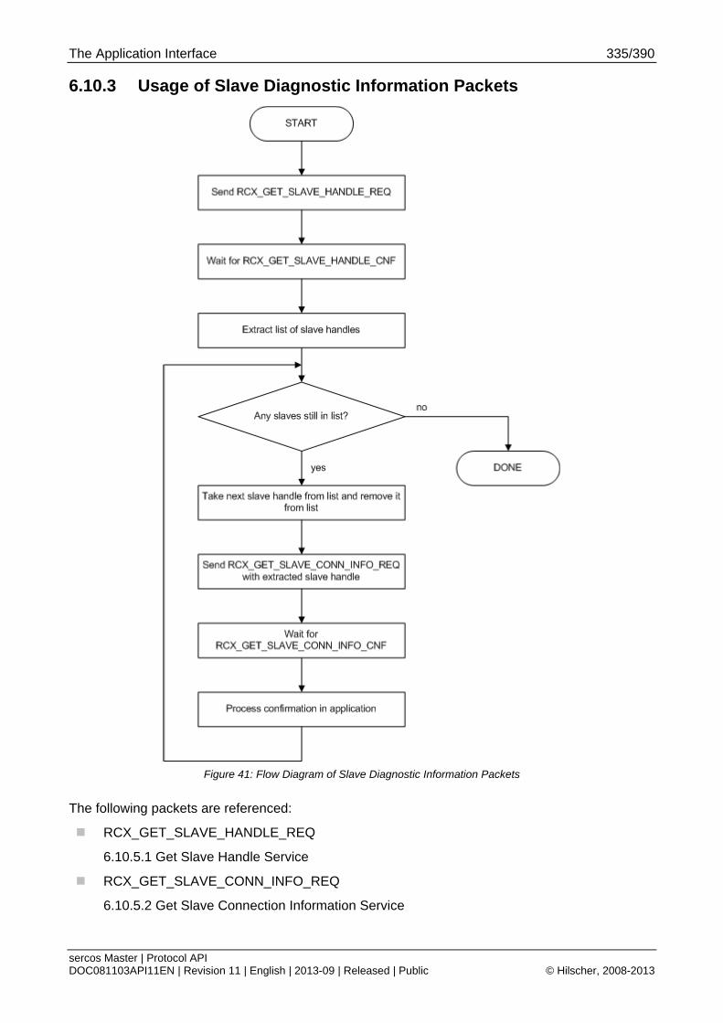
The Application Interface 335/390
sercos Master | Protocol API DOC081103API11EN | Revision 11 | English | 2013-09 | Released | Public © Hilscher, 2008-2013
6.10.3 Usage of Slave Diagnostic Information Packets
Figure 41: Flow Diagram of Slave Diagnostic Information Packets
The following packets are referenced:
RCX_GET_SLAVE_HANDLE_REQ
6.10.5.1 Get Slave Handle Service
RCX_GET_SLAVE_CONN_INFO_REQ
6.10.5.2 Get Slave Connection Information Service
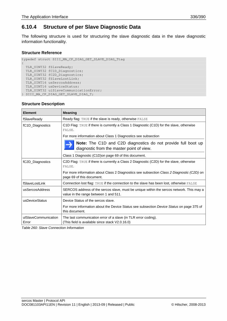
The Application Interface 336/390
sercos Master | Protocol API DOC081103API11EN | Revision 11 | English | 2013-09 | Released | Public © Hilscher, 2008-2013
6.10.4 Structure of per Slave Diagnostic Data
The following structure is used for structuring the slave diagnostic data in the slave diagnostic information functionality.
Structure Reference
typedef struct SIII_MA_CP_DIAG_GET_SLAVE_DIAG_Ttag { TLR_UINT32 fSlaveReady; TLR_UINT32 fC1D_Diagnostics; TLR_UINT32 fC2D_Diagnostics; TLR_UINT32 fSlaveLostLink; TLR_UINT16 usSercosAddress; TLR_UINT16 usDeviceStatus; TLR_UINT32 ulSlaveCommunicationError; } SIII_MA_CP_DIAG_GET_SLAVE_DIAG_T;
Structure Description
Element Meaning
fSlaveReady Ready flag: TRUE if the slave is ready, otherwise FALSE
fC1D_Diagnostics C1D Flag: TRUE if there is currently a Class 1 Diagnostic (C1D) for the slave, otherwise FALSE.
For more information about Class 1 Diagnostics see subsection
Note: The C1D and C2D diagnostics do not provide full boot up diagnostic from the master point of view.
Class 1 Diagnostic (C1D)on page 69 of this document.
fC2D_Diagnostics C2D Flag: TRUE if there is currently a Class 2 Diagnostic (C2D) for the slave, otherwise FALSE.
For more information about Class 2 Diagnostics see subsection Class 2 Diagnostic (C2D) on page 69 of this document.
fSlaveLostLink Connection lost flag: TRUE if the connection to the slave has been lost, otherwise FALSE
usSercosAddress SERCOS address of the sercos slave, must be unique within the sercos network. This may a value in the range between 1 and 511.
usDeviceStatus Device Status of the sercos slave.
For more information about the Device Status see subsection Device Status on page 375 of this document.
ulSlaveCommunicationError
The last communication error of a slave (in TLR error coding). (This field is available since stack V2.0.16.0)
Table 260: Slave Connection Information
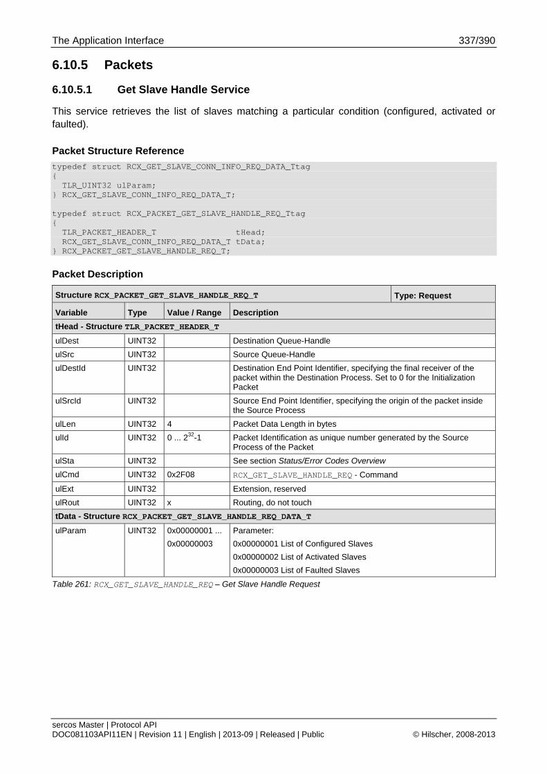
The Application Interface 337/390
sercos Master | Protocol API DOC081103API11EN | Revision 11 | English | 2013-09 | Released | Public © Hilscher, 2008-2013
6.10.5 Packets
6.10.5.1 Get Slave Handle Service
This service retrieves the list of slaves matching a particular condition (configured, activated or faulted).
Packet Structure Reference
typedef struct RCX_GET_SLAVE_CONN_INFO_REQ_DATA_Ttag { TLR_UINT32 ulParam; } RCX_GET_SLAVE_CONN_INFO_REQ_DATA_T; typedef struct RCX_PACKET_GET_SLAVE_HANDLE_REQ_Ttag { TLR_PACKET_HEADER_T tHead; RCX_GET_SLAVE_CONN_INFO_REQ_DATA_T tData; } RCX_PACKET_GET_SLAVE_HANDLE_REQ_T;
Packet Description
Structure RCX_PACKET_GET_SLAVE_HANDLE_REQ_T Type: Request
Variable Type Value / Range Description
tHead - Structure TLR_PACKET_HEADER_T
ulDest UINT32 Destination Queue-Handle
ulSrc UINT32 Source Queue-Handle
ulDestId UINT32 Destination End Point Identifier, specifying the final receiver of the packet within the Destination Process. Set to 0 for the Initialization Packet
ulSrcId UINT32 Source End Point Identifier, specifying the origin of the packet inside the Source Process
ulLen UINT32 4 Packet Data Length in bytes
ulId UINT32 0 ... 232-1 Packet Identification as unique number generated by the Source Process of the Packet
ulSta UINT32 See section Status/Error Codes Overview
ulCmd UINT32 0x2F08 RCX_GET_SLAVE_HANDLE_REQ - Command
ulExt UINT32 Extension, reserved
ulRout UINT32 x Routing, do not touch
tData - Structure RCX_PACKET_GET_SLAVE_HANDLE_REQ_DATA_T
ulParam UINT32 0x00000001 ...
0x00000003
Parameter:
0x00000001 List of Configured Slaves
0x00000002 List of Activated Slaves
0x00000003 List of Faulted Slaves
Table 261: RCX_GET_SLAVE_HANDLE_REQ – Get Slave Handle Request
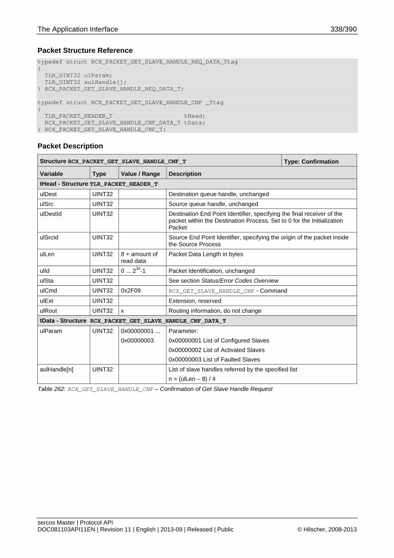
The Application Interface 338/390
sercos Master | Protocol API DOC081103API11EN | Revision 11 | English | 2013-09 | Released | Public © Hilscher, 2008-2013
Packet Structure Reference
typedef struct RCX_PACKET_GET_SLAVE_HANDLE_REQ_DATA_Ttag { TLR_UINT32 ulParam; TLR_UINT32 aulHandle[]; } RCX_PACKET_GET_SLAVE_HANDLE_REQ_DATA_T; typedef struct RCX_PACKET_GET_SLAVE_HANDLE_CNF _Ttag { TLR_PACKET_HEADER_T tHead; RCX_PACKET_GET_SLAVE_HANDLE_CNF_DATA_T tData; } RCX_PACKET_GET_SLAVE_HANDLE_CNF_T;
Packet Description
Structure RCX_PACKET_GET_SLAVE_HANDLE_CNF_T Type: Confirmation
Variable Type Value / Range Description
tHead - Structure TLR_PACKET_HEADER_T
ulDest UINT32 Destination queue handle, unchanged
ulSrc UINT32 Source queue handle, unchanged
ulDestId UINT32 Destination End Point Identifier, specifying the final receiver of the packet within the Destination Process. Set to 0 for the Initialization Packet
ulSrcId UINT32 Source End Point Identifier, specifying the origin of the packet inside the Source Process
ulLen UINT32 8 + amount of read data
Packet Data Length in bytes
ulId UINT32 0 ... 232-1 Packet Identification, unchanged
ulSta UINT32 See section Status/Error Codes Overview
ulCmd UINT32 0x2F09 RCX_GET_SLAVE_HANDLE_CNF - Command
ulExt UINT32 Extension, reserved
ulRout UINT32 x Routing information, do not change
tData - Structure RCX_PACKET_GET_SLAVE_HANDLE_CNF_DATA_T
ulParam UINT32 0x00000001 ...
0x00000003
Parameter:
0x00000001 List of Configured Slaves
0x00000002 List of Activated Slaves
0x00000003 List of Faulted Slaves
aulHandle[n] UINT32 List of slave handles referred by the specified list
n = (ulLen – 8) / 4
Table 262: RCX_GET_SLAVE_HANDLE_CNF – Confirmation of Get Slave Handle Request
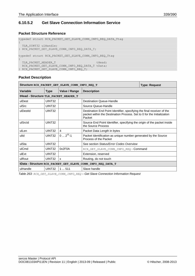
The Application Interface 339/390
sercos Master | Protocol API DOC081103API11EN | Revision 11 | English | 2013-09 | Released | Public © Hilscher, 2008-2013
6.10.5.2 Get Slave Connection Information Service
Packet Structure Reference
typedef struct RCX_PACKET_GET_SLAVE_CONN_INFO_REQ_DATA_Ttag { TLR_UINT32 ulHandle; } RCX_PACKET_GET_SLAVE_CONN_INFO_REQ_DATA_T; typedef struct RCX_PACKET_GET_SLAVE_CONN_INFO_REQ_Ttag { TLR_PACKET_HEADER_T tHead; RCX_PACKET_GET_SLAVE_CONN_INFO_REQ_DATA_T tData; } RCX_PACKET_GET_SLAVE_CONN_INFO_REQ_T;
Packet Description
Structure RCX_PACKET_GET_SLAVE_CONN_INFO_REQ_T Type: Request
Variable Type Value / Range Description
tHead - Structure TLR_PACKET_HEADER_T
ulDest UINT32 Destination Queue-Handle
ulSrc UINT32 Source Queue-Handle
ulDestId UINT32 Destination End Point Identifier, specifying the final receiver of the packet within the Destination Process. Set to 0 for the Initialization Packet
ulSrcId UINT32 Source End Point Identifier, specifying the origin of the packet inside the Source Process
ulLen UINT32 4 Packet Data Length in bytes
ulId UINT32 0 ... 232-1 Packet Identification as unique number generated by the Source Process of the Packet
ulSta UINT32 See section Status/Error Codes Overview
ulCmd UINT32 0x2F0A RCX_GET_SLAVE_CONN_INFO_REQ - Command
ulExt UINT32 Extension, reserved
ulRout UINT32 x Routing, do not touch
tData - Structure RCX_PACKET_GET_SLAVE_CONN_INFO_REQ_DATA_T
ulHandle UINT32 1 ... 511 Slave handle
Table 263: RCX_GET_SLAVE_CONN_INFO_REQ – Get Slave Connection Information Request
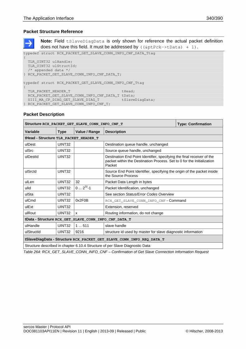
The Application Interface 340/390
sercos Master | Protocol API DOC081103API11EN | Revision 11 | English | 2013-09 | Released | Public © Hilscher, 2008-2013
Packet Structure Reference
Note: Field tSlaveDiagData is only shown for reference the actual packet definition does not have this field. It must be addressed by ((&ptPck->tData) + 1).
typedef struct RCX_PACKET_GET_SLAVE_CONN_INFO_CNF_DATA_Ttag { TLR_UINT32 ulHandle; TLR_UINT32 ulStructId; /* appended data */ } RCX_PACKET_GET_SLAVE_CONN_INFO_CNF_DATA_T; typedef struct RCX_PACKET_GET_SLAVE_CONN_INFO_CNF_Ttag { TLR_PACKET_HEADER_T tHead; RCX_PACKET_GET_SLAVE_CONN_INFO_CNF_DATA_T tData; SIII_MA_CP_DIAG_GET_SLAVE_DIAG_T tSlaveDiagData; } RCX_PACKET_GET_SLAVE_CONN_INFO_CNF_T;
Packet Description
Structure RCX_PACKET_GET_SLAVE_CONN_INFO_CNF_T Type: Confirmation
Variable Type Value / Range Description
tHead - Structure TLR_PACKET_HEADER_T
ulDest UINT32 Destination queue handle, unchanged
ulSrc UINT32 Source queue handle, unchanged
ulDestId UINT32 Destination End Point Identifier, specifying the final receiver of the packet within the Destination Process. Set to 0 for the Initialization Packet
ulSrcId UINT32 Source End Point Identifier, specifying the origin of the packet inside the Source Process
ulLen UINT32 32 Packet Data Length in bytes
ulId UINT32 0 ... 232-1 Packet Identification, unchanged
ulSta UINT32 See section Status/Error Codes Overview
ulCmd UINT32 0x2F0B RCX_GET_SLAVE_CONN_INFO_CNF - Command
ulExt UINT32 Extension, reserved
ulRout UINT32 x Routing information, do not change
tData - Structure RCX_GET_SLAVE_CONN_INFO_CNF_DATA_T
ulHandle UINT32 1 ... 511 slave handle
ulStructId UINT32 9216 structure id used by master for slave diagnostic information
tSlaveDiagData - Structure RCX_PACKET_GET_SLAVE_CONN_INFO_REQ_DATA_T
Structure described in chapter 6.10.4 Structure of per Slave Diagnostic Data
Table 264: RCX_GET_SLAVE_CONN_INFO_CNF – Confirmation of Get Slave Connection Information Request
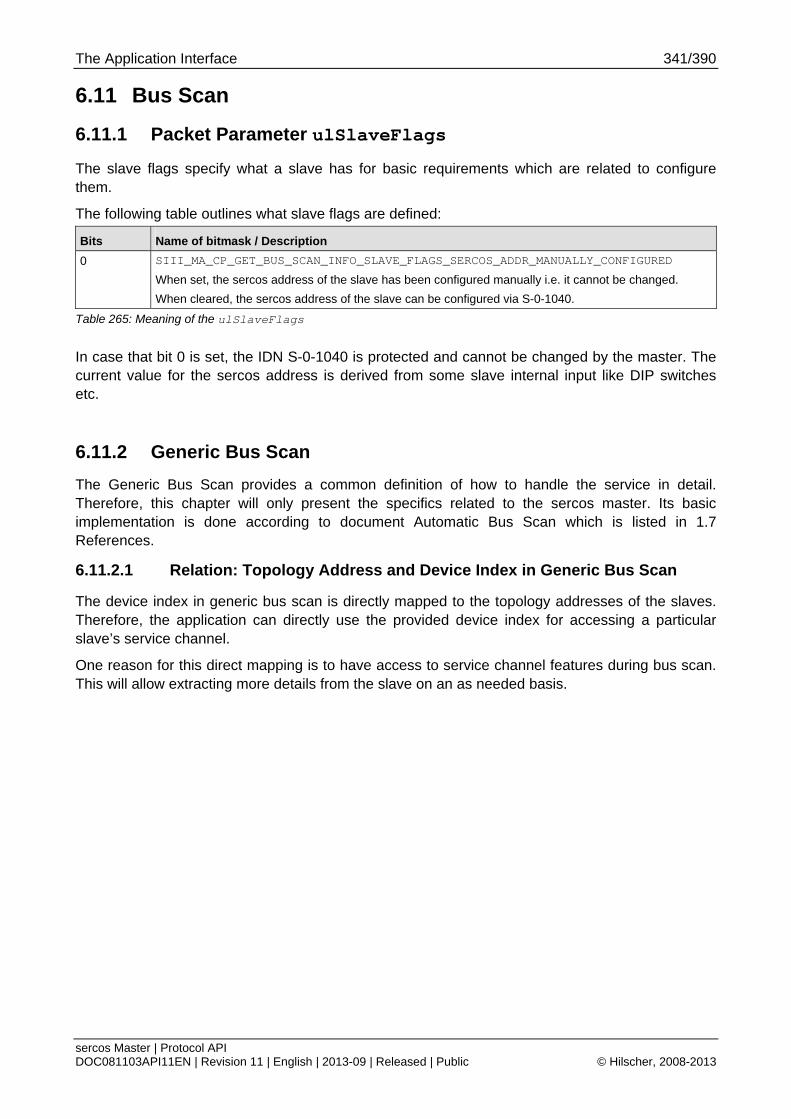
The Application Interface 341/390
sercos Master | Protocol API DOC081103API11EN | Revision 11 | English | 2013-09 | Released | Public © Hilscher, 2008-2013
6.11 Bus Scan
6.11.1 Packet Parameter ulSlaveFlags
The slave flags specify what a slave has for basic requirements which are related to configure them.
The following table outlines what slave flags are defined:
Bits Name of bitmask / Description
0 SIII_MA_CP_GET_BUS_SCAN_INFO_SLAVE_FLAGS_SERCOS_ADDR_MANUALLY_CONFIGURED
When set, the sercos address of the slave has been configured manually i.e. it cannot be changed.
When cleared, the sercos address of the slave can be configured via S-0-1040.
Table 265: Meaning of the ulSlaveFlags
In case that bit 0 is set, the IDN S-0-1040 is protected and cannot be changed by the master. The current value for the sercos address is derived from some slave internal input like DIP switches etc.
6.11.2 Generic Bus Scan
The Generic Bus Scan provides a common definition of how to handle the service in detail. Therefore, this chapter will only present the specifics related to the sercos master. Its basic implementation is done according to document Automatic Bus Scan which is listed in 1.7 References.
6.11.2.1 Relation: Topology Address and Device Index in Generic Bus Scan
The device index in generic bus scan is directly mapped to the topology addresses of the slaves. Therefore, the application can directly use the provided device index for accessing a particular slave’s service channel.
One reason for this direct mapping is to have access to service channel features during bus scan. This will allow extracting more details from the slave on an as needed basis.

The Application Interface 342/390
sercos Master | Protocol API DOC081103API11EN | Revision 11 | English | 2013-09 | Released | Public © Hilscher, 2008-2013
6.11.2.2 Get Device Info Service
This service is used to request the current device information of a connected slave and has sercos specific parts which will be shown here.
Packet Structure Reference
typedef struct RCX_GET_DEVICE_INFO_REQ_DATA_Ttag { TLR_UINT32 ulDeviceIdx; } RCX_GET_DEVICE_INFO_REQ_DATA_T; typedef struct RCX_GET_DEVICE_INFO_REQ_Ttag { TLR_PACKET_HEADER_T tHead; RCX_GET_DEVICE_INFO_REQ_DATA_T tData; } RCX_GET_DEVICE_INFO_REQ_T;
Packet Description
Structure RCX_GET_DEVICE_INFO_REQ_T Type: Confirmation
Variable Type Value / Range Description
tHead - Structure TLR_PACKET_HEADER_T
ulDest UINT32 Destination Queue-Handle
ulSrc UINT32 Source Queue-Handle
ulDestId UINT32 Destination End Point Identifier, specifying the final receiver of the packet within the Destination Process. Set to 0 for the Initialization Packet
ulSrcId UINT32 Source End Point Identifier, specifying the origin of the packet inside the Source Process
ulLen UINT32 4 Packet Data Length in bytes
ulId UINT32 0 ... 232-1 Packet Identification as unique number generated by the Source Process of the Packet
ulSta UINT32 See section Status/Error Codes Overview
ulCmd UINT32 0x2F24 RCX_GET_DEVICE_INFO_REQ - Command
ulExt UINT32 0 Extension not in use, set to zero for compatibility reasons
ulRout UINT32 x Routing, do not touch
tData - Structure RCX_GET_DEVICE_INFO_REQ_DATA_T
ulDeviceIdx UINT32 Device index
Table 266: RCX_GET_DEVICE_INFO_REQ – Get Device Info Request

The Application Interface 343/390
sercos Master | Protocol API DOC081103API11EN | Revision 11 | English | 2013-09 | Released | Public © Hilscher, 2008-2013
Packet Structure Reference
typedef struct RCX_GET_DEVICE_INFO_CNF_DATA_Ttag { TLR_UINT32 ulDeviceIdx; TLR_UINT32 ulStructId; } RCX_GET_DEVICE_INFO_CNF_DATA_T; typedef struct SIII_MA_CP_GET_DEVICE_INFO_Ttag { TLR_UINT16 usSercosAddress; TLR_UINT16 usVendorCode; TLR_UINT8 abDeviceID[256]; TLR_UINT8 bZero; TLR_UINT32 ulSlaveFlags; } SIII_MA_CP_GET_DEVICE_INFO_T; typedef struct RCX_GET_DEVICE_INFO_CNF_Ttag { TLR_PACKET_HEADER_T tHead; RCX_GET_DEVICE_INFO_CNF_DATA_T tData; SIII_MA_CP_GET_DEVICE_INFO_T tDevInfoData; } RCX_GET_DEVICE_INFO_CNF_T;
Note: tDevInfoData is not part of the RCX_GET_DEVICE_INFO_CNF_T. It is merely shown where it is placed. It must be addressed by ((&ptPck->tData) + 1).
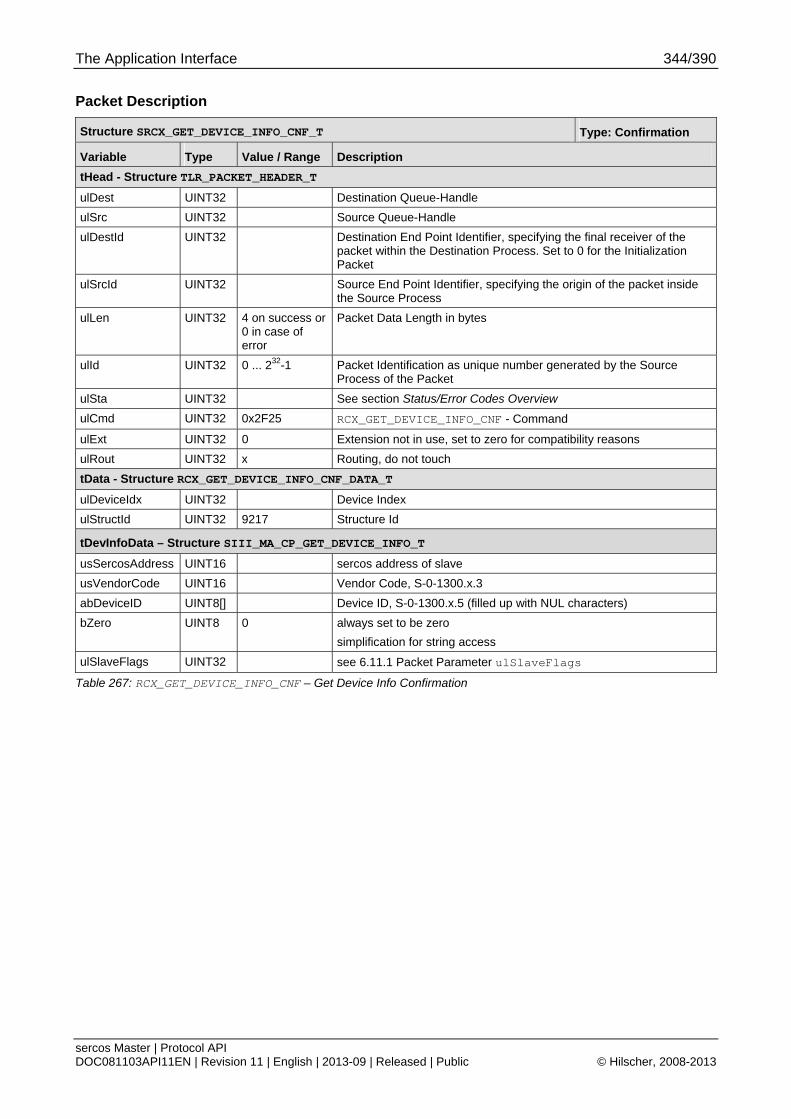
The Application Interface 344/390
sercos Master | Protocol API DOC081103API11EN | Revision 11 | English | 2013-09 | Released | Public © Hilscher, 2008-2013
Packet Description
Structure SRCX_GET_DEVICE_INFO_CNF_T Type: Confirmation
Variable Type Value / Range Description
tHead - Structure TLR_PACKET_HEADER_T
ulDest UINT32 Destination Queue-Handle
ulSrc UINT32 Source Queue-Handle
ulDestId UINT32 Destination End Point Identifier, specifying the final receiver of the packet within the Destination Process. Set to 0 for the Initialization Packet
ulSrcId UINT32 Source End Point Identifier, specifying the origin of the packet inside the Source Process
ulLen UINT32 4 on success or 0 in case of error
Packet Data Length in bytes
ulId UINT32 0 ... 232-1 Packet Identification as unique number generated by the Source Process of the Packet
ulSta UINT32 See section Status/Error Codes Overview
ulCmd UINT32 0x2F25 RCX_GET_DEVICE_INFO_CNF - Command
ulExt UINT32 0 Extension not in use, set to zero for compatibility reasons
ulRout UINT32 x Routing, do not touch
tData - Structure RCX_GET_DEVICE_INFO_CNF_DATA_T
ulDeviceIdx UINT32 Device Index
ulStructId UINT32 9217 Structure Id
tDevInfoData – Structure SIII_MA_CP_GET_DEVICE_INFO_T
usSercosAddress UINT16 sercos address of slave
usVendorCode UINT16 Vendor Code, S-0-1300.x.3
abDeviceID UINT8[] Device ID, S-0-1300.x.5 (filled up with NUL characters)
bZero UINT8 0 always set to be zero
simplification for string access
ulSlaveFlags UINT32 see 6.11.1 Packet Parameter ulSlaveFlags
Table 267: RCX_GET_DEVICE_INFO_CNF – Get Device Info Confirmation
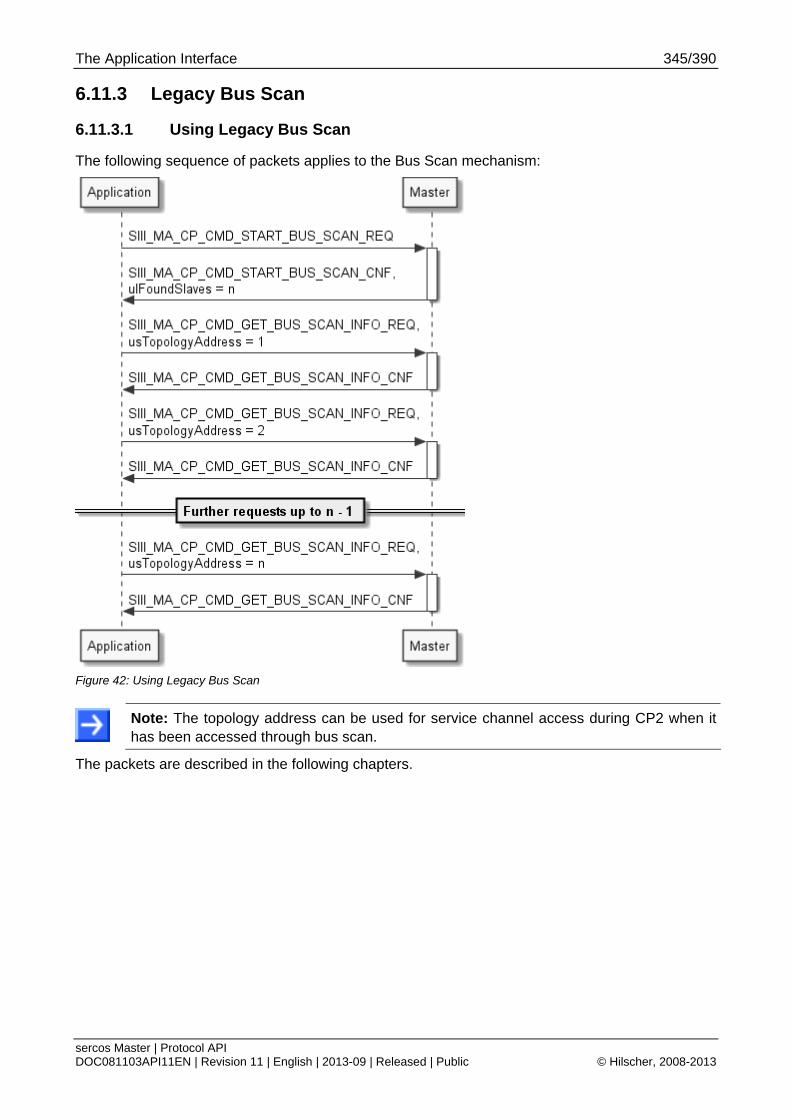
The Application Interface 345/390
sercos Master | Protocol API DOC081103API11EN | Revision 11 | English | 2013-09 | Released | Public © Hilscher, 2008-2013
6.11.3 Legacy Bus Scan
6.11.3.1 Using Legacy Bus Scan
The following sequence of packets applies to the Bus Scan mechanism:
Figure 42: Using Legacy Bus Scan
Note: The topology address can be used for service channel access during CP2 when it has been accessed through bus scan.
The packets are described in the following chapters.
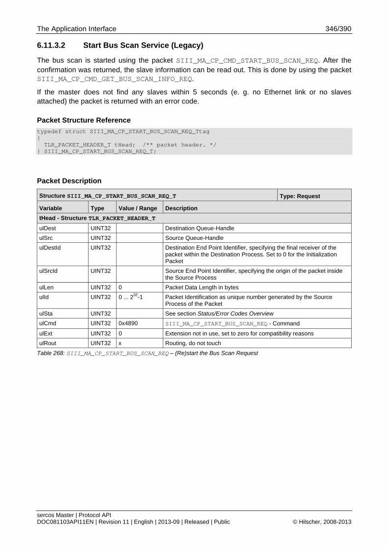
The Application Interface 346/390
sercos Master | Protocol API DOC081103API11EN | Revision 11 | English | 2013-09 | Released | Public © Hilscher, 2008-2013
6.11.3.2 Start Bus Scan Service (Legacy)
The bus scan is started using the packet SIII_MA_CP_CMD_START_BUS_SCAN_REQ. After the confirmation was returned, the slave information can be read out. This is done by using the packet SIII_MA_CP_CMD_GET_BUS_SCAN_INFO_REQ.
If the master does not find any slaves within 5 seconds (e. g. no Ethernet link or no slaves attached) the packet is returned with an error code.
Packet Structure Reference
typedef struct SIII_MA_CP_START_BUS_SCAN_REQ_Ttag { TLR_PACKET_HEADER_T tHead; /** packet header. */ } SIII_MA_CP_START_BUS_SCAN_REQ_T;
Packet Description
Structure SIII_MA_CP_START_BUS_SCAN_REQ_T Type: Request
Variable Type Value / Range Description
tHead - Structure TLR_PACKET_HEADER_T
ulDest UINT32 Destination Queue-Handle
ulSrc UINT32 Source Queue-Handle
ulDestId UINT32 Destination End Point Identifier, specifying the final receiver of the packet within the Destination Process. Set to 0 for the Initialization Packet
ulSrcId UINT32 Source End Point Identifier, specifying the origin of the packet inside the Source Process
ulLen UINT32 0 Packet Data Length in bytes
ulId UINT32 0 ... 232-1 Packet Identification as unique number generated by the Source Process of the Packet
ulSta UINT32 See section Status/Error Codes Overview
ulCmd UINT32 0x4890 SIII_MA_CP_START_BUS_SCAN_REQ - Command
ulExt UINT32 0 Extension not in use, set to zero for compatibility reasons
ulRout UINT32 x Routing, do not touch
Table 268: SIII_MA_CP_START_BUS_SCAN_REQ – (Re)start the Bus Scan Request
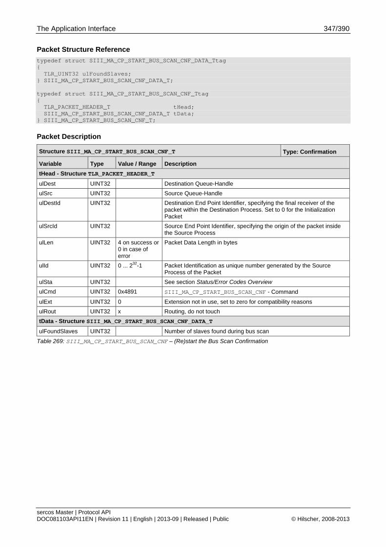
The Application Interface 347/390
sercos Master | Protocol API DOC081103API11EN | Revision 11 | English | 2013-09 | Released | Public © Hilscher, 2008-2013
Packet Structure Reference
typedef struct SIII_MA_CP_START_BUS_SCAN_CNF_DATA_Ttag { TLR_UINT32 ulFoundSlaves; } SIII_MA_CP_START_BUS_SCAN_CNF_DATA_T; typedef struct SIII_MA_CP_START_BUS_SCAN_CNF_Ttag { TLR_PACKET_HEADER_T tHead; SIII_MA_CP_START_BUS_SCAN_CNF_DATA_T tData; } SIII_MA_CP_START_BUS_SCAN_CNF_T;
Packet Description
Structure SIII_MA_CP_START_BUS_SCAN_CNF_T Type: Confirmation
Variable Type Value / Range Description
tHead - Structure TLR_PACKET_HEADER_T
ulDest UINT32 Destination Queue-Handle
ulSrc UINT32 Source Queue-Handle
ulDestId UINT32 Destination End Point Identifier, specifying the final receiver of the packet within the Destination Process. Set to 0 for the Initialization Packet
ulSrcId UINT32 Source End Point Identifier, specifying the origin of the packet inside the Source Process
ulLen UINT32 4 on success or 0 in case of error
Packet Data Length in bytes
ulId UINT32 0 ... 232-1 Packet Identification as unique number generated by the Source Process of the Packet
ulSta UINT32 See section Status/Error Codes Overview
ulCmd UINT32 0x4891 SIII_MA_CP_START_BUS_SCAN_CNF - Command
ulExt UINT32 0 Extension not in use, set to zero for compatibility reasons
ulRout UINT32 x Routing, do not touch
tData - Structure SIII_MA_CP_START_BUS_SCAN_CNF_DATA_T
ulFoundSlaves UINT32 Number of slaves found during bus scan
Table 269: SIII_MA_CP_START_BUS_SCAN_CNF – (Re)start the Bus Scan Confirmation

The Application Interface 348/390
sercos Master | Protocol API DOC081103API11EN | Revision 11 | English | 2013-09 | Released | Public © Hilscher, 2008-2013
6.11.3.3 Get Bus Scan Results Service (Legacy)
This packet provides access to the data being collected by a preceding bus scan.
The actual confirmation packet will carry the following information which is related to the Electronic Label:
SERCOS address
Vendor Code
DeviceID
Slave Flags
Packet Structure Reference
typedef struct SIII_MA_CP_GET_BUS_SCAN_INFO_REQ_DATA_Ttag { TLR_UINT16 usTopologyAddress; } SIII_MA_CP_GET_BUS_SCAN_INFO_REQ_DATA_T; typedef struct SIII_MA_CP_GET_BUS_SCAN_INFO_REQ_Ttag { TLR_PACKET_HEADER_T tHead; SIII_MA_CP_GET_BUS_SCAN_INFO_REQ_DATA_T tData; } SIII_MA_CP_GET_BUS_SCAN_INFO_REQ_T;
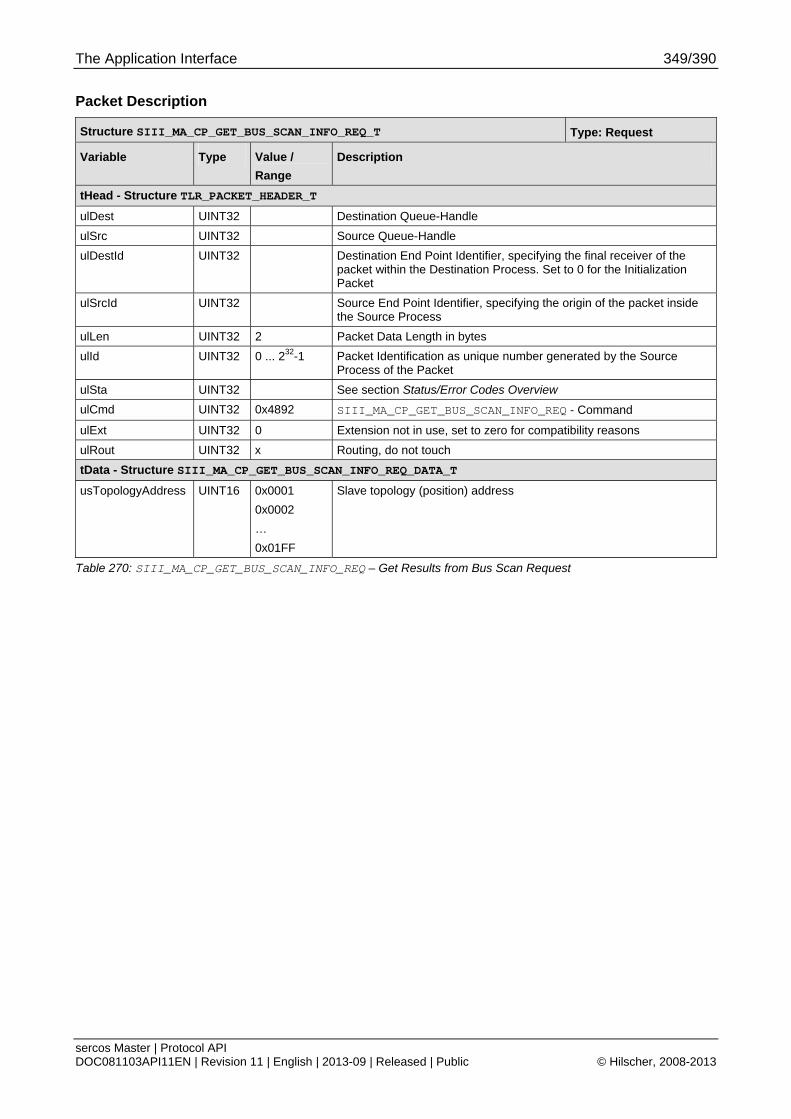
The Application Interface 349/390
sercos Master | Protocol API DOC081103API11EN | Revision 11 | English | 2013-09 | Released | Public © Hilscher, 2008-2013
Packet Description
Structure SIII_MA_CP_GET_BUS_SCAN_INFO_REQ_T Type: Request
Variable Type Value /
Range
Description
tHead - Structure TLR_PACKET_HEADER_T
ulDest UINT32 Destination Queue-Handle
ulSrc UINT32 Source Queue-Handle
ulDestId UINT32 Destination End Point Identifier, specifying the final receiver of the packet within the Destination Process. Set to 0 for the Initialization Packet
ulSrcId UINT32 Source End Point Identifier, specifying the origin of the packet inside the Source Process
ulLen UINT32 2 Packet Data Length in bytes
ulId UINT32 0 ... 232-1 Packet Identification as unique number generated by the Source Process of the Packet
ulSta UINT32 See section Status/Error Codes Overview
ulCmd UINT32 0x4892 SIII_MA_CP_GET_BUS_SCAN_INFO_REQ - Command
ulExt UINT32 0 Extension not in use, set to zero for compatibility reasons
ulRout UINT32 x Routing, do not touch
tData - Structure SIII_MA_CP_GET_BUS_SCAN_INFO_REQ_DATA_T
usTopologyAddress UINT16 0x0001
0x0002
…
0x01FF
Slave topology (position) address
Table 270: SIII_MA_CP_GET_BUS_SCAN_INFO_REQ – Get Results from Bus Scan Request
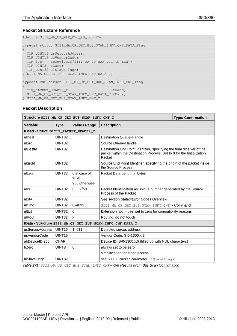
The Application Interface 350/390
sercos Master | Protocol API DOC081103API11EN | Revision 11 | English | 2013-09 | Released | Public © Hilscher, 2008-2013
Packet Structure Reference
#define SIII_MA_CP_MAX_DVC_ID_LEN 256 typedef struct SIII_MA_CP_GET_BUS_SCAN_INFO_CNF_DATA_Ttag { TLR_UINT16 usSercosAddress; TLR_UINT16 usVendorCode; TLR_STR abDeviceID[SIII_MA_CP_MAX_DVC_ID_LEN]; TLR_UINT8 bZero; TLR_UINT32 ulSlaveFlags; } SIII_MA_CP_GET_BUS_SCAN_INFO_CNF_DATA_T; typedef PRE struct SIII_MA_CP_GET_BUS_SCAN_INFO_CNF_Ttag { TLR_PACKET_HEADER_T tHead; SIII_MA_CP_GET_BUS_SCAN_INFO_CNF_DATA_T tData; } SIII_MA_CP_GET_BUS_SCAN_INFO_CNF_T;
Packet Description
Structure SIII_MA_CP_GET_BUS_SCAN_INFO_CNF_T Type: Confirmation
Variable Type Value / Range Description
tHead - Structure TLR_PACKET_HEADER_T
ulDest UINT32 Destination Queue-Handle
ulSrc UINT32 Source Queue-Handle
ulDestId UINT32 Destination End Point Identifier, specifying the final receiver of the packet within the Destination Process. Set to 0 for the Initialization Packet
ulSrcId UINT32 Source End Point Identifier, specifying the origin of the packet inside the Source Process
ulLen UINT32 0 in case of error
265 otherwise
Packet Data Length in bytes
ulId UINT32 0 ... 232-1 Packet Identification as unique number generated by the Source Process of the Packet
ulSta UINT32 See section Status/Error Codes Overview
ulCmd UINT32 0x4893 SIII_MA_CP_GET_BUS_SCAN_INFO_CNF - Command
ulExt UINT32 0 Extension not in use, set to zero for compatibility reasons
ulRout UINT32 x Routing, do not touch
tData - Structure SIII_MA_CP_GET_BUS_SCAN_INFO_CNF_DATA_T
usSercosAddress UINT16 1..511 Detected sercos address
usVendorCode UINT16 Vendor Code, S-0-1300.x.3
abDeviceID[256] CHAR[ ] Device ID, S-0-1300.x.5 (filled up with NUL characters)
bZero UINT8 0 always set to be zero
simplification for string access
ulSlaveFlags UINT32 see 6.11.1 Packet Parameter ulSlaveFlags
Table 271: SIII_MA_CP_GET_BUS_SCAN_INFO_CNF – Get Results From Bus Scan Confirmation
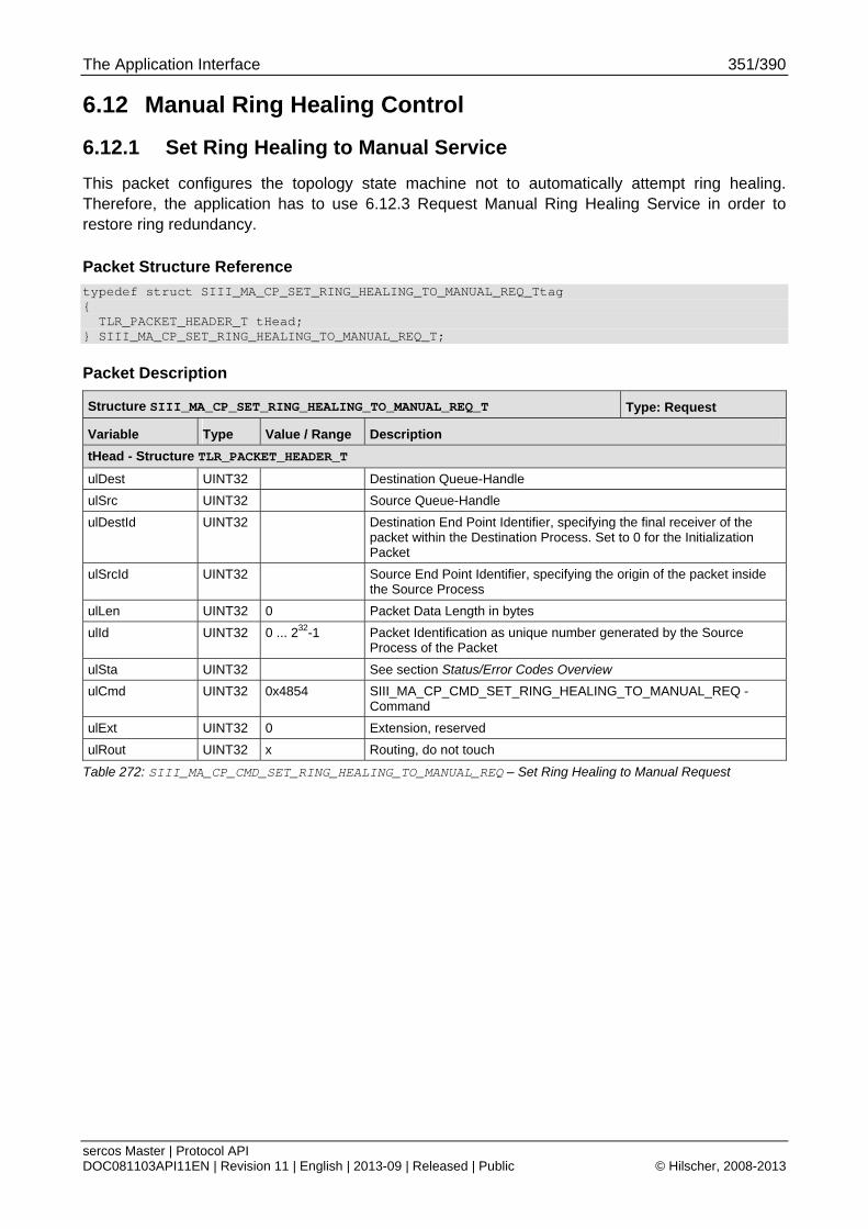
The Application Interface 351/390
sercos Master | Protocol API DOC081103API11EN | Revision 11 | English | 2013-09 | Released | Public © Hilscher, 2008-2013
6.12 Manual Ring Healing Control
6.12.1 Set Ring Healing to Manual Service
This packet configures the topology state machine not to automatically attempt ring healing. Therefore, the application has to use 6.12.3 Request Manual Ring Healing Service in order to restore ring redundancy.
Packet Structure Reference
typedef struct SIII_MA_CP_SET_RING_HEALING_TO_MANUAL_REQ_Ttag { TLR_PACKET_HEADER_T tHead; } SIII_MA_CP_SET_RING_HEALING_TO_MANUAL_REQ_T;
Packet Description
Structure SIII_MA_CP_SET_RING_HEALING_TO_MANUAL_REQ_T Type: Request
Variable Type Value / Range Description
tHead - Structure TLR_PACKET_HEADER_T
ulDest UINT32 Destination Queue-Handle
ulSrc UINT32 Source Queue-Handle
ulDestId UINT32 Destination End Point Identifier, specifying the final receiver of the packet within the Destination Process. Set to 0 for the Initialization Packet
ulSrcId UINT32 Source End Point Identifier, specifying the origin of the packet inside the Source Process
ulLen UINT32 0 Packet Data Length in bytes
ulId UINT32 0 ... 232-1 Packet Identification as unique number generated by the Source Process of the Packet
ulSta UINT32 See section Status/Error Codes Overview
ulCmd UINT32 0x4854 SIII_MA_CP_CMD_SET_RING_HEALING_TO_MANUAL_REQ - Command
ulExt UINT32 0 Extension, reserved
ulRout UINT32 x Routing, do not touch
Table 272: SIII_MA_CP_CMD_SET_RING_HEALING_TO_MANUAL_REQ – Set Ring Healing to Manual Request
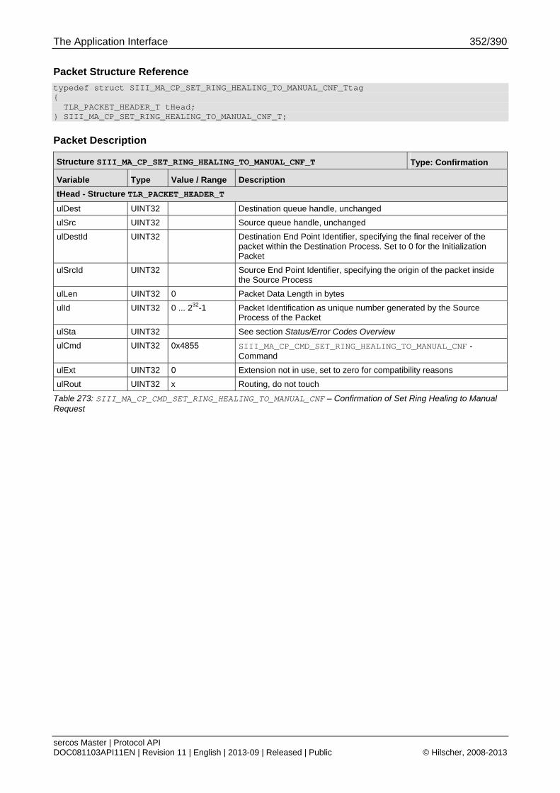
The Application Interface 352/390
sercos Master | Protocol API DOC081103API11EN | Revision 11 | English | 2013-09 | Released | Public © Hilscher, 2008-2013
Packet Structure Reference
typedef struct SIII_MA_CP_SET_RING_HEALING_TO_MANUAL_CNF_Ttag { TLR_PACKET_HEADER_T tHead; } SIII_MA_CP_SET_RING_HEALING_TO_MANUAL_CNF_T;
Packet Description
Structure SIII_MA_CP_SET_RING_HEALING_TO_MANUAL_CNF_T Type: Confirmation
Variable Type Value / Range Description
tHead - Structure TLR_PACKET_HEADER_T
ulDest UINT32 Destination queue handle, unchanged
ulSrc UINT32 Source queue handle, unchanged
ulDestId UINT32 Destination End Point Identifier, specifying the final receiver of the packet within the Destination Process. Set to 0 for the Initialization Packet
ulSrcId UINT32 Source End Point Identifier, specifying the origin of the packet inside the Source Process
ulLen UINT32 0 Packet Data Length in bytes
ulId UINT32 0 ... 232-1 Packet Identification as unique number generated by the Source Process of the Packet
ulSta UINT32 See section Status/Error Codes Overview
ulCmd UINT32 0x4855 SIII_MA_CP_CMD_SET_RING_HEALING_TO_MANUAL_CNF - Command
ulExt UINT32 0 Extension not in use, set to zero for compatibility reasons
ulRout UINT32 x Routing, do not touch
Table 273: SIII_MA_CP_CMD_SET_RING_HEALING_TO_MANUAL_CNF – Confirmation of Set Ring Healing to Manual Request
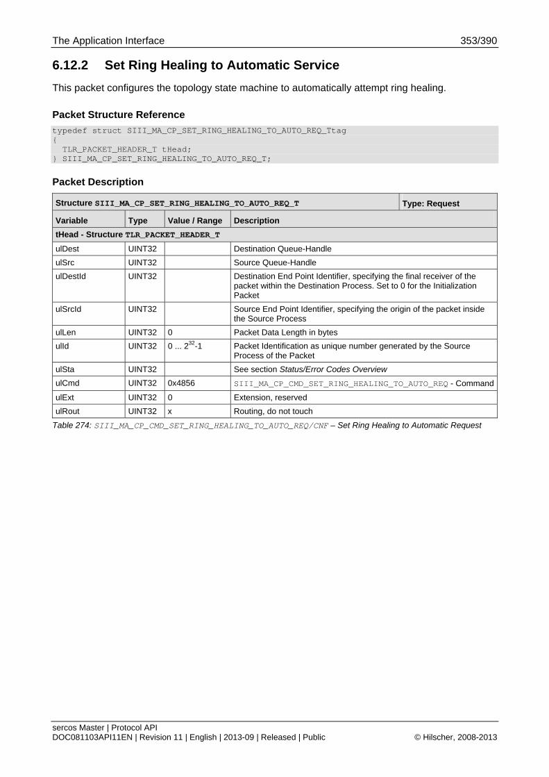
The Application Interface 353/390
sercos Master | Protocol API DOC081103API11EN | Revision 11 | English | 2013-09 | Released | Public © Hilscher, 2008-2013
6.12.2 Set Ring Healing to Automatic Service
This packet configures the topology state machine to automatically attempt ring healing.
Packet Structure Reference
typedef struct SIII_MA_CP_SET_RING_HEALING_TO_AUTO_REQ_Ttag { TLR_PACKET_HEADER_T tHead; } SIII_MA_CP_SET_RING_HEALING_TO_AUTO_REQ_T;
Packet Description
Structure SIII_MA_CP_SET_RING_HEALING_TO_AUTO_REQ_T Type: Request
Variable Type Value / Range Description
tHead - Structure TLR_PACKET_HEADER_T
ulDest UINT32 Destination Queue-Handle
ulSrc UINT32 Source Queue-Handle
ulDestId UINT32 Destination End Point Identifier, specifying the final receiver of the packet within the Destination Process. Set to 0 for the Initialization Packet
ulSrcId UINT32 Source End Point Identifier, specifying the origin of the packet inside the Source Process
ulLen UINT32 0 Packet Data Length in bytes
ulId UINT32 0 ... 232-1 Packet Identification as unique number generated by the Source Process of the Packet
ulSta UINT32 See section Status/Error Codes Overview
ulCmd UINT32 0x4856 SIII_MA_CP_CMD_SET_RING_HEALING_TO_AUTO_REQ - Command
ulExt UINT32 0 Extension, reserved
ulRout UINT32 x Routing, do not touch
Table 274: SIII_MA_CP_CMD_SET_RING_HEALING_TO_AUTO_REQ/CNF – Set Ring Healing to Automatic Request
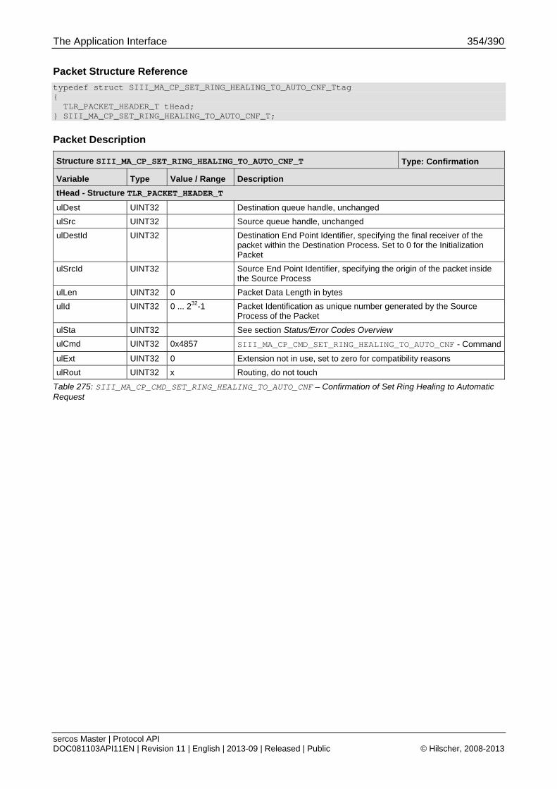
The Application Interface 354/390
sercos Master | Protocol API DOC081103API11EN | Revision 11 | English | 2013-09 | Released | Public © Hilscher, 2008-2013
Packet Structure Reference
typedef struct SIII_MA_CP_SET_RING_HEALING_TO_AUTO_CNF_Ttag { TLR_PACKET_HEADER_T tHead; } SIII_MA_CP_SET_RING_HEALING_TO_AUTO_CNF_T;
Packet Description
Structure SIII_MA_CP_SET_RING_HEALING_TO_AUTO_CNF_T Type: Confirmation
Variable Type Value / Range Description
tHead - Structure TLR_PACKET_HEADER_T
ulDest UINT32 Destination queue handle, unchanged
ulSrc UINT32 Source queue handle, unchanged
ulDestId UINT32 Destination End Point Identifier, specifying the final receiver of the packet within the Destination Process. Set to 0 for the Initialization Packet
ulSrcId UINT32 Source End Point Identifier, specifying the origin of the packet inside the Source Process
ulLen UINT32 0 Packet Data Length in bytes
ulId UINT32 0 ... 232-1 Packet Identification as unique number generated by the Source Process of the Packet
ulSta UINT32 See section Status/Error Codes Overview
ulCmd UINT32 0x4857 SIII_MA_CP_CMD_SET_RING_HEALING_TO_AUTO_CNF - Command
ulExt UINT32 0 Extension not in use, set to zero for compatibility reasons
ulRout UINT32 x Routing, do not touch
Table 275: SIII_MA_CP_CMD_SET_RING_HEALING_TO_AUTO_CNF – Confirmation of Set Ring Healing to Automatic Request
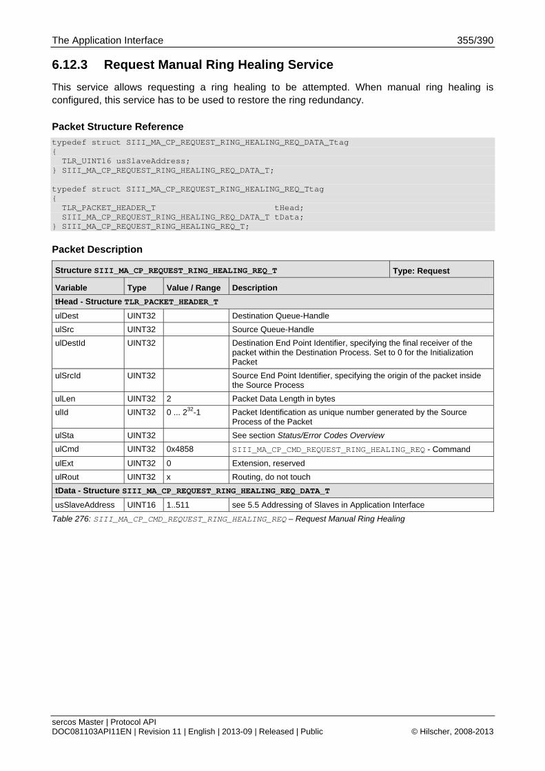
The Application Interface 355/390
sercos Master | Protocol API DOC081103API11EN | Revision 11 | English | 2013-09 | Released | Public © Hilscher, 2008-2013
6.12.3 Request Manual Ring Healing Service
This service allows requesting a ring healing to be attempted. When manual ring healing is configured, this service has to be used to restore the ring redundancy.
Packet Structure Reference
typedef struct SIII_MA_CP_REQUEST_RING_HEALING_REQ_DATA_Ttag { TLR_UINT16 usSlaveAddress; } SIII_MA_CP_REQUEST_RING_HEALING_REQ_DATA_T; typedef struct SIII_MA_CP_REQUEST_RING_HEALING_REQ_Ttag { TLR_PACKET_HEADER_T tHead; SIII_MA_CP_REQUEST_RING_HEALING_REQ_DATA_T tData; } SIII_MA_CP_REQUEST_RING_HEALING_REQ_T;
Packet Description
Structure SIII_MA_CP_REQUEST_RING_HEALING_REQ_T Type: Request
Variable Type Value / Range Description
tHead - Structure TLR_PACKET_HEADER_T
ulDest UINT32 Destination Queue-Handle
ulSrc UINT32 Source Queue-Handle
ulDestId UINT32 Destination End Point Identifier, specifying the final receiver of the packet within the Destination Process. Set to 0 for the Initialization Packet
ulSrcId UINT32 Source End Point Identifier, specifying the origin of the packet inside the Source Process
ulLen UINT32 2 Packet Data Length in bytes
ulId UINT32 0 ... 232-1 Packet Identification as unique number generated by the Source Process of the Packet
ulSta UINT32 See section Status/Error Codes Overview
ulCmd UINT32 0x4858 SIII_MA_CP_CMD_REQUEST_RING_HEALING_REQ - Command
ulExt UINT32 0 Extension, reserved
ulRout UINT32 x Routing, do not touch
tData - Structure SIII_MA_CP_REQUEST_RING_HEALING_REQ_DATA_T
usSlaveAddress UINT16 1..511 see 5.5 Addressing of Slaves in Application Interface
Table 276: SIII_MA_CP_CMD_REQUEST_RING_HEALING_REQ – Request Manual Ring Healing

The Application Interface 356/390
sercos Master | Protocol API DOC081103API11EN | Revision 11 | English | 2013-09 | Released | Public © Hilscher, 2008-2013
Packet Structure Reference
typedef struct SIII_MA_CP_REQUEST_RING_HEALING_CNF_Ttag { TLR_PACKET_HEADER_T tHead; } SIII_MA_CP_REQUEST_RING_HEALING_CNF_T;
Packet Description
Structure SIII_MA_CP_REQUEST_RING_HEALING_CNF_T Type: Confirmation
Variable Type Value / Range Description
tHead - Structure TLR_PACKET_HEADER_T
ulDest UINT32 Destination queue handle, unchanged
ulSrc UINT32 Source queue handle, unchanged
ulDestId UINT32 Destination End Point Identifier, specifying the final receiver of the packet within the Destination Process. Set to 0 for the Initialization Packet
ulSrcId UINT32 Source End Point Identifier, specifying the origin of the packet inside the Source Process
ulLen UINT32 0 Packet Data Length in bytes
ulId UINT32 0 ... 232-1 Packet Identification as unique number generated by the Source Process of the Packet
ulSta UINT32 See section Status/Error Codes Overview
ulCmd UINT32 0x4859 SIII_MA_CP_CMD_REQUEST_RING_HEALING_CNF - Command
ulExt UINT32 0 Extension not in use, set to zero for compatibility reasons
ulRout UINT32 x Routing, do not touch
Table 277: SIII_MA_CP_CMD_REQUEST_RING_HEALING_CNF – Confirmation of Manual Ring Healing Request
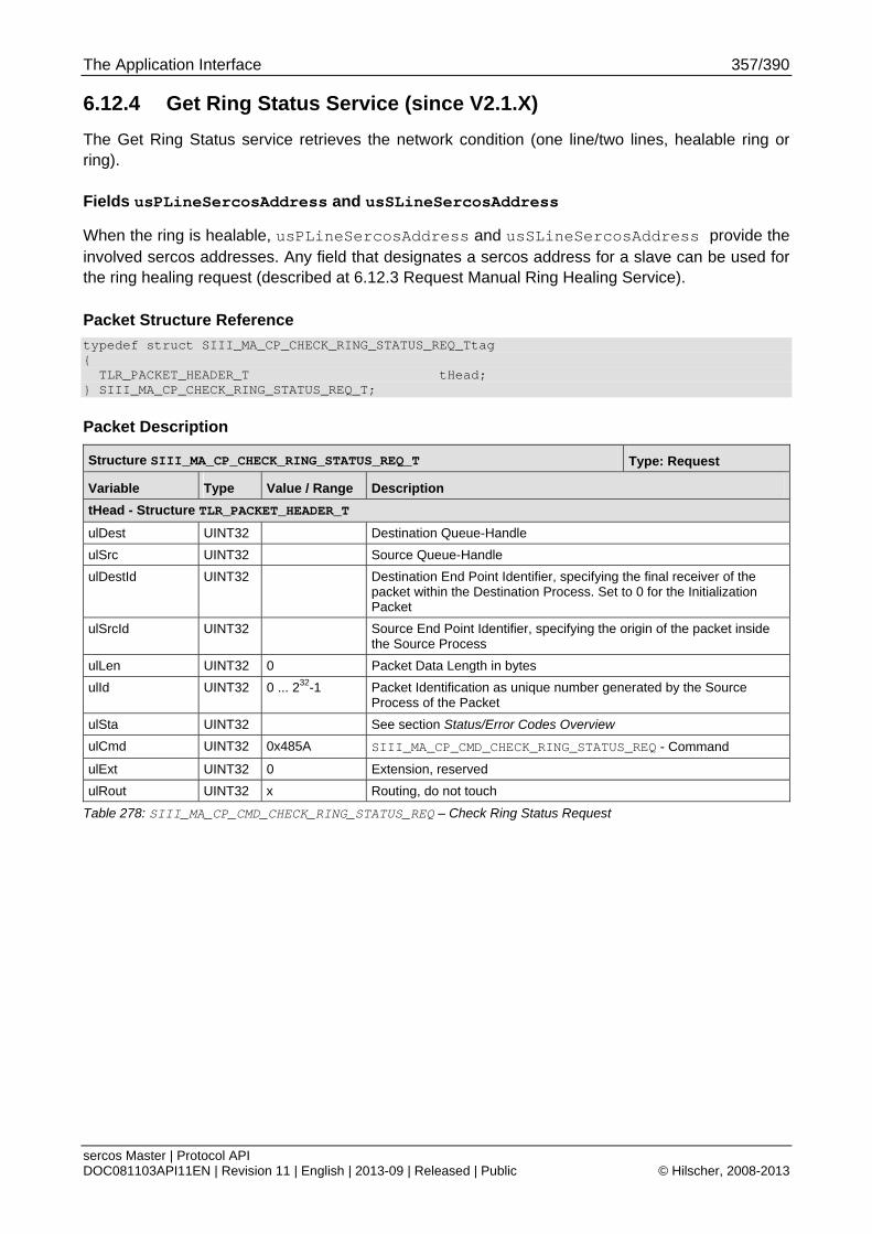
The Application Interface 357/390
sercos Master | Protocol API DOC081103API11EN | Revision 11 | English | 2013-09 | Released | Public © Hilscher, 2008-2013
6.12.4 Get Ring Status Service (since V2.1.X)
The Get Ring Status service retrieves the network condition (one line/two lines, healable ring or ring).
Fields usPLineSercosAddress and usSLineSercosAddress
When the ring is healable, usPLineSercosAddress and usSLineSercosAddress provide the involved sercos addresses. Any field that designates a sercos address for a slave can be used for the ring healing request (described at 6.12.3 Request Manual Ring Healing Service).
Packet Structure Reference
typedef struct SIII_MA_CP_CHECK_RING_STATUS_REQ_Ttag { TLR_PACKET_HEADER_T tHead; } SIII_MA_CP_CHECK_RING_STATUS_REQ_T;
Packet Description
Structure SIII_MA_CP_CHECK_RING_STATUS_REQ_T Type: Request
Variable Type Value / Range Description
tHead - Structure TLR_PACKET_HEADER_T
ulDest UINT32 Destination Queue-Handle
ulSrc UINT32 Source Queue-Handle
ulDestId UINT32 Destination End Point Identifier, specifying the final receiver of the packet within the Destination Process. Set to 0 for the Initialization Packet
ulSrcId UINT32 Source End Point Identifier, specifying the origin of the packet inside the Source Process
ulLen UINT32 0 Packet Data Length in bytes
ulId UINT32 0 ... 232-1 Packet Identification as unique number generated by the Source Process of the Packet
ulSta UINT32 See section Status/Error Codes Overview
ulCmd UINT32 0x485A SIII_MA_CP_CMD_CHECK_RING_STATUS_REQ - Command
ulExt UINT32 0 Extension, reserved
ulRout UINT32 x Routing, do not touch
Table 278: SIII_MA_CP_CMD_CHECK_RING_STATUS_REQ – Check Ring Status Request
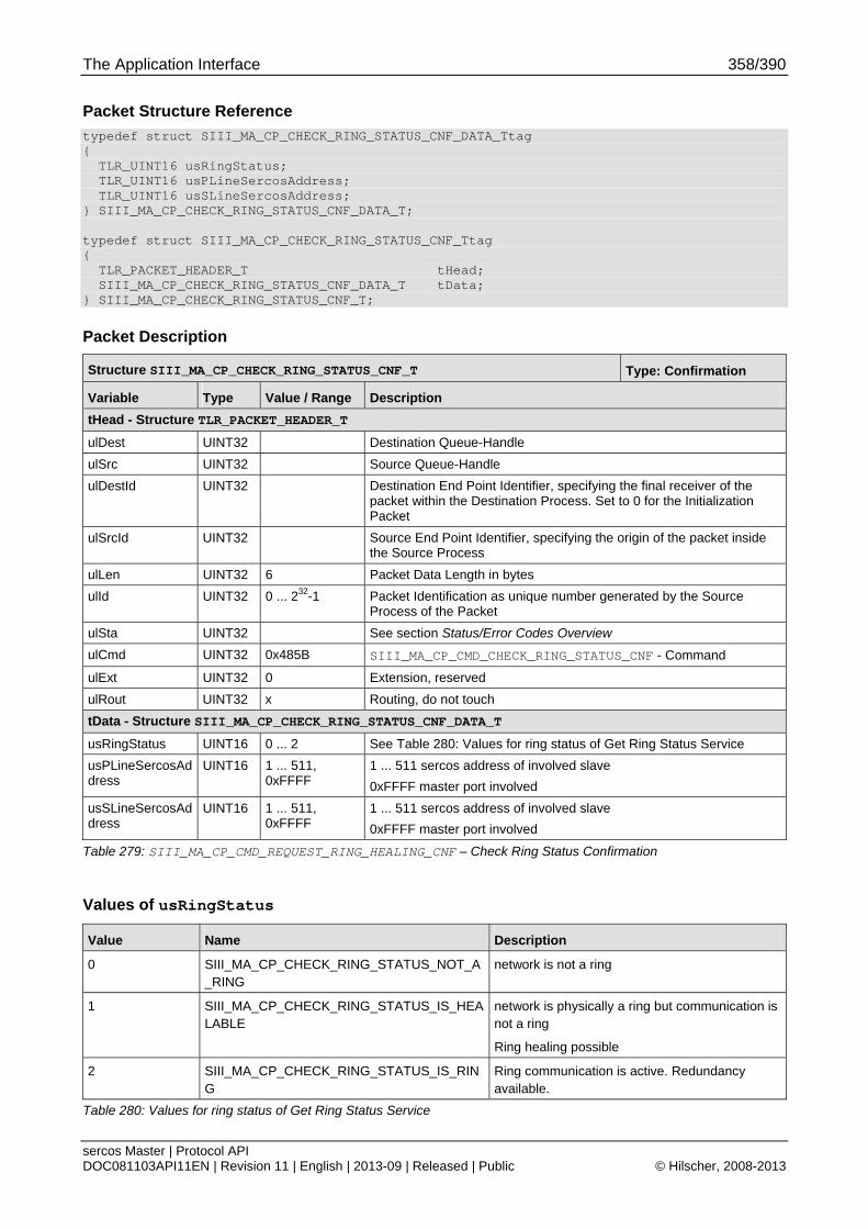
The Application Interface 358/390
sercos Master | Protocol API DOC081103API11EN | Revision 11 | English | 2013-09 | Released | Public © Hilscher, 2008-2013
Packet Structure Reference
typedef struct SIII_MA_CP_CHECK_RING_STATUS_CNF_DATA_Ttag { TLR_UINT16 usRingStatus; TLR_UINT16 usPLineSercosAddress; TLR_UINT16 usSLineSercosAddress; } SIII_MA_CP_CHECK_RING_STATUS_CNF_DATA_T; typedef struct SIII_MA_CP_CHECK_RING_STATUS_CNF_Ttag { TLR_PACKET_HEADER_T tHead; SIII_MA_CP_CHECK_RING_STATUS_CNF_DATA_T tData; } SIII_MA_CP_CHECK_RING_STATUS_CNF_T;
Packet Description
Structure SIII_MA_CP_CHECK_RING_STATUS_CNF_T Type: Confirmation
Variable Type Value / Range Description
tHead - Structure TLR_PACKET_HEADER_T
ulDest UINT32 Destination Queue-Handle
ulSrc UINT32 Source Queue-Handle
ulDestId UINT32 Destination End Point Identifier, specifying the final receiver of the packet within the Destination Process. Set to 0 for the Initialization Packet
ulSrcId UINT32 Source End Point Identifier, specifying the origin of the packet inside the Source Process
ulLen UINT32 6 Packet Data Length in bytes
ulId UINT32 0 ... 232-1 Packet Identification as unique number generated by the Source Process of the Packet
ulSta UINT32 See section Status/Error Codes Overview
ulCmd UINT32 0x485B SIII_MA_CP_CMD_CHECK_RING_STATUS_CNF - Command
ulExt UINT32 0 Extension, reserved
ulRout UINT32 x Routing, do not touch
tData - Structure SIII_MA_CP_CHECK_RING_STATUS_CNF_DATA_T
usRingStatus UINT16 0 ... 2 See Table 280: Values for ring status of Get Ring Status Service
usPLineSercosAddress
UINT16 1 ... 511, 0xFFFF
1 ... 511 sercos address of involved slave
0xFFFF master port involved
usSLineSercosAddress
UINT16 1 ... 511, 0xFFFF
1 ... 511 sercos address of involved slave
0xFFFF master port involved
Table 279: SIII_MA_CP_CMD_REQUEST_RING_HEALING_CNF – Check Ring Status Confirmation
Values of usRingStatus
Value Name Description
0 SIII_MA_CP_CHECK_RING_STATUS_NOT_A_RING
network is not a ring
1 SIII_MA_CP_CHECK_RING_STATUS_IS_HEALABLE
network is physically a ring but communication is not a ring
Ring healing possible
2 SIII_MA_CP_CHECK_RING_STATUS_IS_RING
Ring communication is active. Redundancy available.
Table 280: Values for ring status of Get Ring Status Service

The Application Interface 359/390
sercos Master | Protocol API DOC081103API11EN | Revision 11 | English | 2013-09 | Released | Public © Hilscher, 2008-2013
6.13 NRT Promiscuous Control
6.13.1 Enable NRT Promiscuous Service
This service enables reception of all unicast destination MAC addresses.
For detailed description of the NRT switch logic, see 5.12 NRT Channel Behavior.
Note: This service does not disable the implemented switch logic.
Packet Structure Reference
typedef struct SIII_MA_NRT_ENABLE_PROMISC_REQ_Ttag { TLR_PACKET_HEADER_T tHead; } SIII_MA_NRT_ENABLE_PROMISC_REQ_T;
Packet Description
Structure SIII_MA_NRT_ENABLE_PROMISC_REQ_T Type: Request
Variable Type Value / Range Description
tHead - Structure TLR_PACKET_HEADER_T
ulDest UINT32 Destination Queue-Handle
ulSrc UINT32 Source Queue-Handle
ulDestId UINT32 Destination End Point Identifier, specifying the final receiver of the packet within the Destination Process. Set to 0 for the Initialization Packet
ulSrcId UINT32 Source End Point Identifier, specifying the origin of the packet inside the Source Process
ulLen UINT32 0 Packet Data Length in bytes
ulId UINT32 0 ... 232-1 Packet Identification as unique number generated by the Source Process of the Packet
ulSta UINT32 See section Status/Error Codes Overview
ulCmd UINT32 0x5020 SIII_MA_CP_CMD_ENABLE_PROMISC_REQ - Command
ulExt UINT32 0 Extension, reserved
ulRout UINT32 x Routing, do not touch
Table 281: SIII_MA_CP_CMD_ENABLE_PROMISC_REQ – Enable NRT Promiscuous Mode Request

The Application Interface 360/390
sercos Master | Protocol API DOC081103API11EN | Revision 11 | English | 2013-09 | Released | Public © Hilscher, 2008-2013
Packet Structure Reference
typedef struct SIII_MA_NRT_ENABLE_PROMISC_CNF_Ttag { TLR_PACKET_HEADER_T tHead; } SIII_MA_NRT_ENABLE_PROMISC_CNF_T;
Packet Description
Structure SIII_MA_NRT_ENABLE_PROMISC_CNF_T Type: Confirmation
Variable Type Value / Range Description
tHead - Structure TLR_PACKET_HEADER_T
ulDest UINT32 Destination Queue-Handle
ulSrc UINT32 Source Queue-Handle
ulDestId UINT32 Destination End Point Identifier, specifying the final receiver of the packet within the Destination Process. Set to 0 for the Initialization Packet
ulSrcId UINT32 Source End Point Identifier, specifying the origin of the packet inside the Source Process
ulLen UINT32 0 Packet Data Length in bytes
ulId UINT32 0 ... 232-1 Packet Identification as unique number generated by the Source Process of the Packet
ulSta UINT32 See section Status/Error Codes Overview
ulCmd UINT32 0x5021 SIII_MA_CP_CMD_ENABLE_PROMISC_CNF - Command
ulExt UINT32 0 Extension, reserved
ulRout UINT32 x Routing, do not touch
Table 282: SIII_MA_CP_CMD_ENABLE_PROMISC_CNF – Enable NRT Promiscuous Mode Confirmation
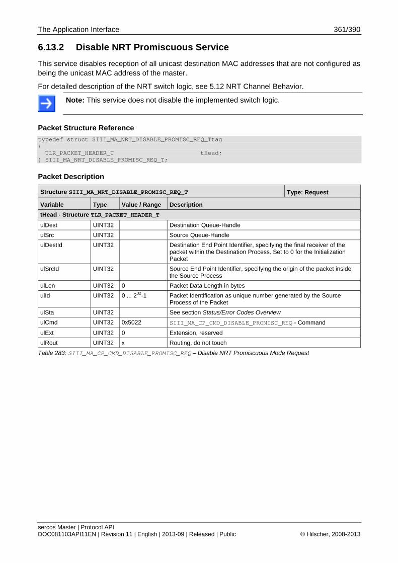
The Application Interface 361/390
sercos Master | Protocol API DOC081103API11EN | Revision 11 | English | 2013-09 | Released | Public © Hilscher, 2008-2013
6.13.2 Disable NRT Promiscuous Service
This service disables reception of all unicast destination MAC addresses that are not configured as being the unicast MAC address of the master.
For detailed description of the NRT switch logic, see 5.12 NRT Channel Behavior.
Note: This service does not disable the implemented switch logic.
Packet Structure Reference
typedef struct SIII_MA_NRT_DISABLE_PROMISC_REQ_Ttag { TLR_PACKET_HEADER_T tHead; } SIII_MA_NRT_DISABLE_PROMISC_REQ_T;
Packet Description
Structure SIII_MA_NRT_DISABLE_PROMISC_REQ_T Type: Request
Variable Type Value / Range Description
tHead - Structure TLR_PACKET_HEADER_T
ulDest UINT32 Destination Queue-Handle
ulSrc UINT32 Source Queue-Handle
ulDestId UINT32 Destination End Point Identifier, specifying the final receiver of the packet within the Destination Process. Set to 0 for the Initialization Packet
ulSrcId UINT32 Source End Point Identifier, specifying the origin of the packet inside the Source Process
ulLen UINT32 0 Packet Data Length in bytes
ulId UINT32 0 ... 232-1 Packet Identification as unique number generated by the Source Process of the Packet
ulSta UINT32 See section Status/Error Codes Overview
ulCmd UINT32 0x5022 SIII_MA_CP_CMD_DISABLE_PROMISC_REQ - Command
ulExt UINT32 0 Extension, reserved
ulRout UINT32 x Routing, do not touch
Table 283: SIII_MA_CP_CMD_DISABLE_PROMISC_REQ – Disable NRT Promiscuous Mode Request

The Application Interface 362/390
sercos Master | Protocol API DOC081103API11EN | Revision 11 | English | 2013-09 | Released | Public © Hilscher, 2008-2013
Packet Structure Reference
typedef struct SIII_MA_NRT_DISABLE_PROMISC_CNF_Ttag { TLR_PACKET_HEADER_T tHead; } SIII_MA_NRT_DISABLE_PROMISC_CNF_T;
Packet Description
Structure SIII_MA_NRT_DISABLE_PROMISC_CNF_T Type: Confirmation
Variable Type Value / Range Description
tHead - Structure TLR_PACKET_HEADER_T
ulDest UINT32 Destination Queue-Handle
ulSrc UINT32 Source Queue-Handle
ulDestId UINT32 Destination End Point Identifier, specifying the final receiver of the packet within the Destination Process. Set to 0 for the Initialization Packet
ulSrcId UINT32 Source End Point Identifier, specifying the origin of the packet inside the Source Process
ulLen UINT32 0 Packet Data Length in bytes
ulId UINT32 0 ... 232-1 Packet Identification as unique number generated by the Source Process of the Packet
ulSta UINT32 See section Status/Error Codes Overview
ulCmd UINT32 0x5023 SIII_MA_CP_CMD_DISABLE_PROMISC_CNF - Command
ulExt UINT32 0 Extension, reserved
ulRout UINT32 x Routing, do not touch
Table 284: SIII_MA_CP_CMD_DISABLE_PROMISC_CNF – Disable NRT Promiscuous Mode Confirmation
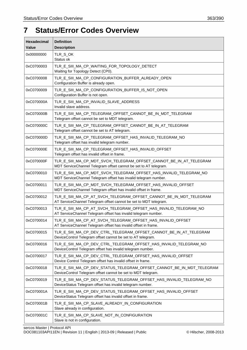
Status/Error Codes Overview 363/390
sercos Master | Protocol API DOC081103API11EN | Revision 11 | English | 2013-09 | Released | Public © Hilscher, 2008-2013
7 Status/Error Codes Overview Hexadecimal
Value
Definition
Description
0x00000000 TLR_S_OK Status ok
0xC0700003 TLR_E_SIII_MA_CP_WAITING_FOR_TOPOLOGY_DETECT Waiting for Topology Detect (CP0).
0xC0700008 TLR_E_SIII_MA_CP_CONFIGURATION_BUFFER_ALREADY_OPEN Configuration Buffer is already open.
0xC0700009 TLR_E_SIII_MA_CP_CONFIGURATION_BUFFER_IS_NOT_OPEN Configuration Buffer is not open.
0xC070000A TLR_E_SIII_MA_CP_INVALID_SLAVE_ADDRESS Invalid slave address.
0xC070000B TLR_E_SIII_MA_CP_TELEGRAM_OFFSET_CANNOT_BE_IN_MDT_TELEGRAM Telegram offset cannot be set to MDT telegram.
0xC070000C TLR_E_SIII_MA_CP_TELEGRAM_OFFSET_CANNOT_BE_IN_AT_TELEGRAM Telegram offset cannot be set to AT telegram.
0xC070000D TLR_E_SIII_MA_CP_TELEGRAM_OFFSET_HAS_INVALID_TELEGRAM_NO Telegram offset has invalid telegram number.
0xC070000E TLR_E_SIII_MA_CP_TELEGRAM_OFFSET_HAS_INVALID_OFFSET Telegram offset has invalid offset in frame.
0xC070000F TLR_E_SIII_MA_CP_MDT_SVCH_TELEGRAM_OFFSET_CANNOT_BE_IN_AT_TELEGRAM MDT ServiceChannel Telegram offset cannot be set to AT telegram.
0xC0700010 TLR_E_SIII_MA_CP_MDT_SVCH_TELEGRAM_OFFSET_HAS_INVALID_TELEGRAM_NO MDT ServiceChannel Telegram offset has invalid telegram number.
0xC0700011 TLR_E_SIII_MA_CP_MDT_SVCH_TELEGRAM_OFFSET_HAS_INVALID_OFFSET MDT ServiceChannel Telegram offset has invalid offset in frame.
0xC0700012 TLR_E_SIII_MA_CP_AT_SVCH_TELEGRAM_OFFSET_CANNOT_BE_IN_MDT_TELEGRAM AT ServiceChannel Telegram offset cannot be set to MDT telegram.
0xC0700013 TLR_E_SIII_MA_CP_AT_SVCH_TELEGRAM_OFFSET_HAS_INVALID_TELEGRAM_NO AT ServiceChannel Telegram offset has invalid telegram number.
0xC0700014 TLR_E_SIII_MA_CP_AT_SVCH_TELEGRAM_OFFSET_HAS_INVALID_OFFSET AT ServiceChannel Telegram offset has invalid offset in frame.
0xC0700015 TLR_E_SIII_MA_CP_DEV_CTRL_TELEGRAM_OFFSET_CANNOT_BE_IN_AT_TELEGRAM DeviceControl Telegram offset cannot be set to AT telegram.
0xC0700016 TLR_E_SIII_MA_CP_DEV_CTRL_TELEGRAM_OFFSET_HAS_INVALID_TELEGRAM_NO DeviceControl Telegram offset has invalid telegram number.
0xC0700017 TLR_E_SIII_MA_CP_DEV_CTRL_TELEGRAM_OFFSET_HAS_INVALID_OFFSET Device Control Telegram offset has invalid offset in frame.
0xC0700018 TLR_E_SIII_MA_CP_DEV_STATUS_TELEGRAM_OFFSET_CANNOT_BE_IN_MDT_TELEGRAM DeviceControl Telegram offset cannot be set to MDT telegram.
0xC0700019 TLR_E_SIII_MA_CP_DEV_STATUS_TELEGRAM_OFFSET_HAS_INVALID_TELEGRAM_NO DeviceStatus Telegram offset has invalid telegram number.
0xC070001A TLR_E_SIII_MA_CP_DEV_STATUS_TELEGRAM_OFFSET_HAS_INVALID_OFFSET DeviceStatus Telegram offset has invalid offset in frame.
0xC070001B TLR_E_SIII_MA_CP_SLAVE_ALREADY_IN_CONFIGURATION Slave already in configuration.
0xC070001C TLR_E_SIII_MA_CP_SLAVE_NOT_IN_CONFIGURATION Slave is not in configuration.
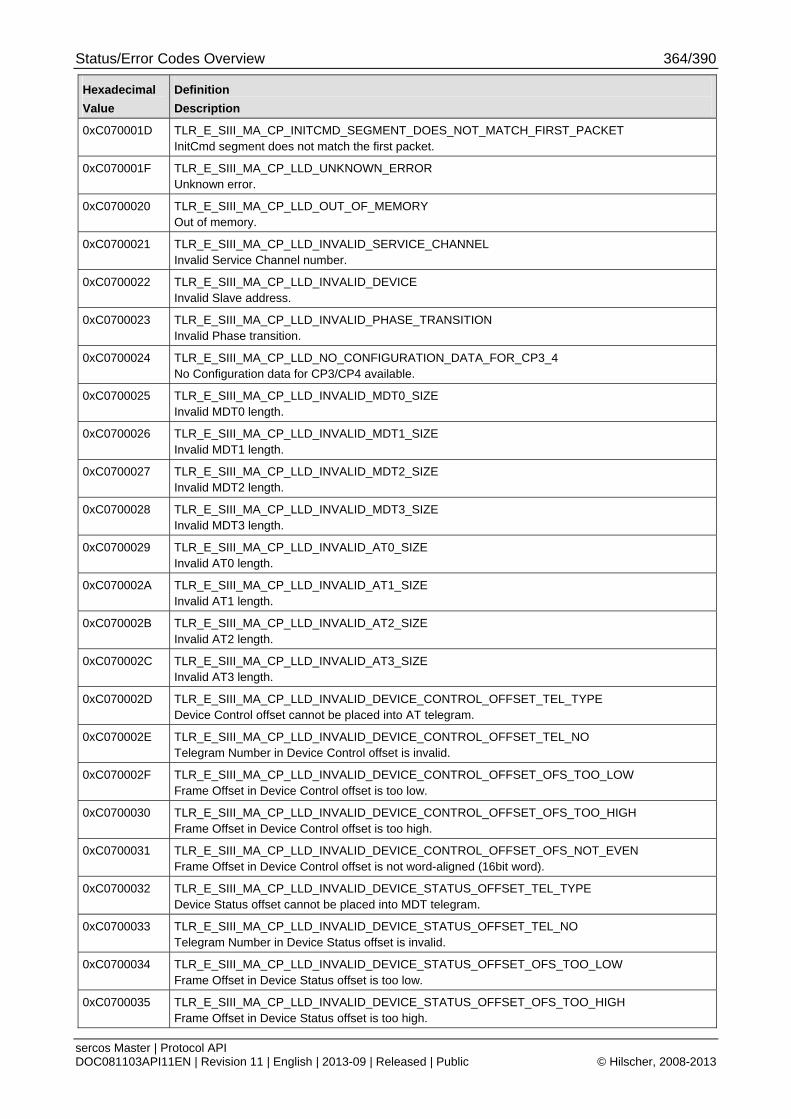
Status/Error Codes Overview 364/390
sercos Master | Protocol API DOC081103API11EN | Revision 11 | English | 2013-09 | Released | Public © Hilscher, 2008-2013
Hexadecimal
Value
Definition
Description
0xC070001D TLR_E_SIII_MA_CP_INITCMD_SEGMENT_DOES_NOT_MATCH_FIRST_PACKET InitCmd segment does not match the first packet.
0xC070001F TLR_E_SIII_MA_CP_LLD_UNKNOWN_ERROR Unknown error.
0xC0700020 TLR_E_SIII_MA_CP_LLD_OUT_OF_MEMORY Out of memory.
0xC0700021 TLR_E_SIII_MA_CP_LLD_INVALID_SERVICE_CHANNEL Invalid Service Channel number.
0xC0700022 TLR_E_SIII_MA_CP_LLD_INVALID_DEVICE Invalid Slave address.
0xC0700023 TLR_E_SIII_MA_CP_LLD_INVALID_PHASE_TRANSITION Invalid Phase transition.
0xC0700024 TLR_E_SIII_MA_CP_LLD_NO_CONFIGURATION_DATA_FOR_CP3_4 No Configuration data for CP3/CP4 available.
0xC0700025 TLR_E_SIII_MA_CP_LLD_INVALID_MDT0_SIZE Invalid MDT0 length.
0xC0700026 TLR_E_SIII_MA_CP_LLD_INVALID_MDT1_SIZE Invalid MDT1 length.
0xC0700027 TLR_E_SIII_MA_CP_LLD_INVALID_MDT2_SIZE Invalid MDT2 length.
0xC0700028 TLR_E_SIII_MA_CP_LLD_INVALID_MDT3_SIZE Invalid MDT3 length.
0xC0700029 TLR_E_SIII_MA_CP_LLD_INVALID_AT0_SIZE Invalid AT0 length.
0xC070002A TLR_E_SIII_MA_CP_LLD_INVALID_AT1_SIZE Invalid AT1 length.
0xC070002B TLR_E_SIII_MA_CP_LLD_INVALID_AT2_SIZE Invalid AT2 length.
0xC070002C TLR_E_SIII_MA_CP_LLD_INVALID_AT3_SIZE Invalid AT3 length.
0xC070002D TLR_E_SIII_MA_CP_LLD_INVALID_DEVICE_CONTROL_OFFSET_TEL_TYPE Device Control offset cannot be placed into AT telegram.
0xC070002E TLR_E_SIII_MA_CP_LLD_INVALID_DEVICE_CONTROL_OFFSET_TEL_NO Telegram Number in Device Control offset is invalid.
0xC070002F TLR_E_SIII_MA_CP_LLD_INVALID_DEVICE_CONTROL_OFFSET_OFS_TOO_LOW Frame Offset in Device Control offset is too low.
0xC0700030 TLR_E_SIII_MA_CP_LLD_INVALID_DEVICE_CONTROL_OFFSET_OFS_TOO_HIGH Frame Offset in Device Control offset is too high.
0xC0700031 TLR_E_SIII_MA_CP_LLD_INVALID_DEVICE_CONTROL_OFFSET_OFS_NOT_EVEN Frame Offset in Device Control offset is not word-aligned (16bit word).
0xC0700032 TLR_E_SIII_MA_CP_LLD_INVALID_DEVICE_STATUS_OFFSET_TEL_TYPE Device Status offset cannot be placed into MDT telegram.
0xC0700033 TLR_E_SIII_MA_CP_LLD_INVALID_DEVICE_STATUS_OFFSET_TEL_NO Telegram Number in Device Status offset is invalid.
0xC0700034 TLR_E_SIII_MA_CP_LLD_INVALID_DEVICE_STATUS_OFFSET_OFS_TOO_LOW Frame Offset in Device Status offset is too low.
0xC0700035 TLR_E_SIII_MA_CP_LLD_INVALID_DEVICE_STATUS_OFFSET_OFS_TOO_HIGH Frame Offset in Device Status offset is too high.
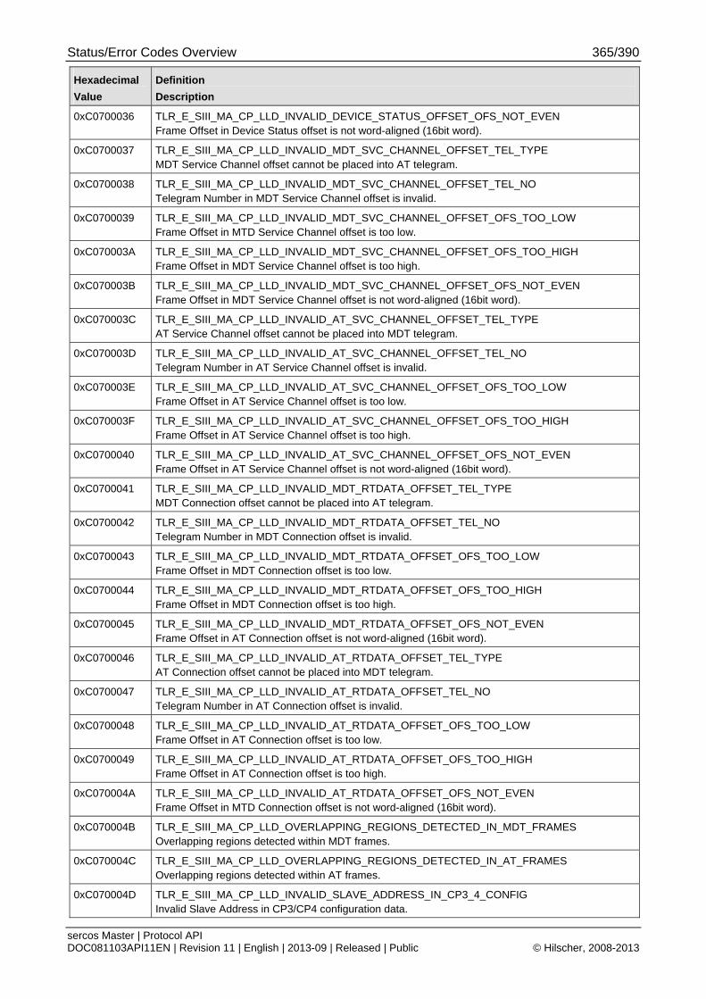
Status/Error Codes Overview 365/390
sercos Master | Protocol API DOC081103API11EN | Revision 11 | English | 2013-09 | Released | Public © Hilscher, 2008-2013
Hexadecimal
Value
Definition
Description
0xC0700036 TLR_E_SIII_MA_CP_LLD_INVALID_DEVICE_STATUS_OFFSET_OFS_NOT_EVEN Frame Offset in Device Status offset is not word-aligned (16bit word).
0xC0700037 TLR_E_SIII_MA_CP_LLD_INVALID_MDT_SVC_CHANNEL_OFFSET_TEL_TYPE MDT Service Channel offset cannot be placed into AT telegram.
0xC0700038 TLR_E_SIII_MA_CP_LLD_INVALID_MDT_SVC_CHANNEL_OFFSET_TEL_NO Telegram Number in MDT Service Channel offset is invalid.
0xC0700039 TLR_E_SIII_MA_CP_LLD_INVALID_MDT_SVC_CHANNEL_OFFSET_OFS_TOO_LOW Frame Offset in MTD Service Channel offset is too low.
0xC070003A TLR_E_SIII_MA_CP_LLD_INVALID_MDT_SVC_CHANNEL_OFFSET_OFS_TOO_HIGH Frame Offset in MDT Service Channel offset is too high.
0xC070003B TLR_E_SIII_MA_CP_LLD_INVALID_MDT_SVC_CHANNEL_OFFSET_OFS_NOT_EVEN Frame Offset in MDT Service Channel offset is not word-aligned (16bit word).
0xC070003C TLR_E_SIII_MA_CP_LLD_INVALID_AT_SVC_CHANNEL_OFFSET_TEL_TYPE AT Service Channel offset cannot be placed into MDT telegram.
0xC070003D TLR_E_SIII_MA_CP_LLD_INVALID_AT_SVC_CHANNEL_OFFSET_TEL_NO Telegram Number in AT Service Channel offset is invalid.
0xC070003E TLR_E_SIII_MA_CP_LLD_INVALID_AT_SVC_CHANNEL_OFFSET_OFS_TOO_LOW Frame Offset in AT Service Channel offset is too low.
0xC070003F TLR_E_SIII_MA_CP_LLD_INVALID_AT_SVC_CHANNEL_OFFSET_OFS_TOO_HIGH Frame Offset in AT Service Channel offset is too high.
0xC0700040 TLR_E_SIII_MA_CP_LLD_INVALID_AT_SVC_CHANNEL_OFFSET_OFS_NOT_EVEN Frame Offset in AT Service Channel offset is not word-aligned (16bit word).
0xC0700041 TLR_E_SIII_MA_CP_LLD_INVALID_MDT_RTDATA_OFFSET_TEL_TYPE MDT Connection offset cannot be placed into AT telegram.
0xC0700042 TLR_E_SIII_MA_CP_LLD_INVALID_MDT_RTDATA_OFFSET_TEL_NO Telegram Number in MDT Connection offset is invalid.
0xC0700043 TLR_E_SIII_MA_CP_LLD_INVALID_MDT_RTDATA_OFFSET_OFS_TOO_LOW Frame Offset in MDT Connection offset is too low.
0xC0700044 TLR_E_SIII_MA_CP_LLD_INVALID_MDT_RTDATA_OFFSET_OFS_TOO_HIGH Frame Offset in MDT Connection offset is too high.
0xC0700045 TLR_E_SIII_MA_CP_LLD_INVALID_MDT_RTDATA_OFFSET_OFS_NOT_EVEN Frame Offset in AT Connection offset is not word-aligned (16bit word).
0xC0700046 TLR_E_SIII_MA_CP_LLD_INVALID_AT_RTDATA_OFFSET_TEL_TYPE AT Connection offset cannot be placed into MDT telegram.
0xC0700047 TLR_E_SIII_MA_CP_LLD_INVALID_AT_RTDATA_OFFSET_TEL_NO Telegram Number in AT Connection offset is invalid.
0xC0700048 TLR_E_SIII_MA_CP_LLD_INVALID_AT_RTDATA_OFFSET_OFS_TOO_LOW Frame Offset in AT Connection offset is too low.
0xC0700049 TLR_E_SIII_MA_CP_LLD_INVALID_AT_RTDATA_OFFSET_OFS_TOO_HIGH Frame Offset in AT Connection offset is too high.
0xC070004A TLR_E_SIII_MA_CP_LLD_INVALID_AT_RTDATA_OFFSET_OFS_NOT_EVEN Frame Offset in MTD Connection offset is not word-aligned (16bit word).
0xC070004B TLR_E_SIII_MA_CP_LLD_OVERLAPPING_REGIONS_DETECTED_IN_MDT_FRAMES Overlapping regions detected within MDT frames.
0xC070004C TLR_E_SIII_MA_CP_LLD_OVERLAPPING_REGIONS_DETECTED_IN_AT_FRAMES Overlapping regions detected within AT frames.
0xC070004D TLR_E_SIII_MA_CP_LLD_INVALID_SLAVE_ADDRESS_IN_CP3_4_CONFIG Invalid Slave Address in CP3/CP4 configuration data.
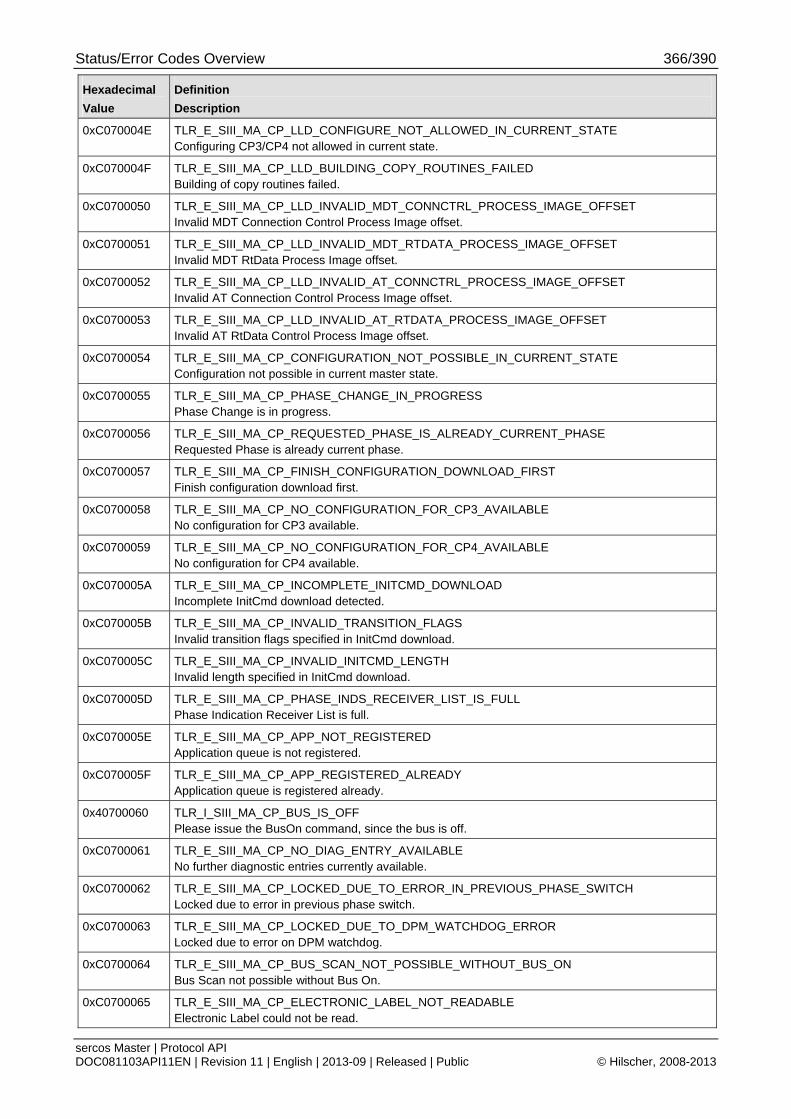
Status/Error Codes Overview 366/390
sercos Master | Protocol API DOC081103API11EN | Revision 11 | English | 2013-09 | Released | Public © Hilscher, 2008-2013
Hexadecimal
Value
Definition
Description
0xC070004E TLR_E_SIII_MA_CP_LLD_CONFIGURE_NOT_ALLOWED_IN_CURRENT_STATE Configuring CP3/CP4 not allowed in current state.
0xC070004F TLR_E_SIII_MA_CP_LLD_BUILDING_COPY_ROUTINES_FAILED Building of copy routines failed.
0xC0700050 TLR_E_SIII_MA_CP_LLD_INVALID_MDT_CONNCTRL_PROCESS_IMAGE_OFFSET Invalid MDT Connection Control Process Image offset.
0xC0700051 TLR_E_SIII_MA_CP_LLD_INVALID_MDT_RTDATA_PROCESS_IMAGE_OFFSET Invalid MDT RtData Process Image offset.
0xC0700052 TLR_E_SIII_MA_CP_LLD_INVALID_AT_CONNCTRL_PROCESS_IMAGE_OFFSET Invalid AT Connection Control Process Image offset.
0xC0700053 TLR_E_SIII_MA_CP_LLD_INVALID_AT_RTDATA_PROCESS_IMAGE_OFFSET Invalid AT RtData Control Process Image offset.
0xC0700054 TLR_E_SIII_MA_CP_CONFIGURATION_NOT_POSSIBLE_IN_CURRENT_STATE Configuration not possible in current master state.
0xC0700055 TLR_E_SIII_MA_CP_PHASE_CHANGE_IN_PROGRESS Phase Change is in progress.
0xC0700056 TLR_E_SIII_MA_CP_REQUESTED_PHASE_IS_ALREADY_CURRENT_PHASE Requested Phase is already current phase.
0xC0700057 TLR_E_SIII_MA_CP_FINISH_CONFIGURATION_DOWNLOAD_FIRST Finish configuration download first.
0xC0700058 TLR_E_SIII_MA_CP_NO_CONFIGURATION_FOR_CP3_AVAILABLE No configuration for CP3 available.
0xC0700059 TLR_E_SIII_MA_CP_NO_CONFIGURATION_FOR_CP4_AVAILABLE No configuration for CP4 available.
0xC070005A TLR_E_SIII_MA_CP_INCOMPLETE_INITCMD_DOWNLOAD Incomplete InitCmd download detected.
0xC070005B TLR_E_SIII_MA_CP_INVALID_TRANSITION_FLAGS Invalid transition flags specified in InitCmd download.
0xC070005C TLR_E_SIII_MA_CP_INVALID_INITCMD_LENGTH Invalid length specified in InitCmd download.
0xC070005D TLR_E_SIII_MA_CP_PHASE_INDS_RECEIVER_LIST_IS_FULL Phase Indication Receiver List is full.
0xC070005E TLR_E_SIII_MA_CP_APP_NOT_REGISTERED Application queue is not registered.
0xC070005F TLR_E_SIII_MA_CP_APP_REGISTERED_ALREADY Application queue is registered already.
0x40700060 TLR_I_SIII_MA_CP_BUS_IS_OFF Please issue the BusOn command, since the bus is off.
0xC0700061 TLR_E_SIII_MA_CP_NO_DIAG_ENTRY_AVAILABLE No further diagnostic entries currently available.
0xC0700062 TLR_E_SIII_MA_CP_LOCKED_DUE_TO_ERROR_IN_PREVIOUS_PHASE_SWITCH Locked due to error in previous phase switch.
0xC0700063 TLR_E_SIII_MA_CP_LOCKED_DUE_TO_DPM_WATCHDOG_ERROR Locked due to error on DPM watchdog.
0xC0700064 TLR_E_SIII_MA_CP_BUS_SCAN_NOT_POSSIBLE_WITHOUT_BUS_ON Bus Scan not possible without Bus On.
0xC0700065 TLR_E_SIII_MA_CP_ELECTRONIC_LABEL_NOT_READABLE Electronic Label could not be read.
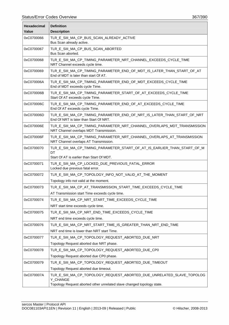
Status/Error Codes Overview 367/390
sercos Master | Protocol API DOC081103API11EN | Revision 11 | English | 2013-09 | Released | Public © Hilscher, 2008-2013
Hexadecimal
Value
Definition
Description
0xC0700066 TLR_E_SIII_MA_CP_BUS_SCAN_ALREADY_ACTIVE Bus Scan already active.
0xC0700067 TLR_E_SIII_MA_CP_BUS_SCAN_ABORTED Bus Scan aborted.
0xC0700068 TLR_E_SIII_MA_CP_TIMING_PARAMETER_NRT_CHANNEL_EXCEEDS_CYCLE_TIME NRT Channel exceeds cycle time.
0xC0700069 TLR_E_SIII_MA_CP_TIMING_PARAMETER_END_OF_MDT_IS_LATER_THAN_START_OF_AT End of MDT is later than start Of AT.
0xC070006A TLR_E_SIII_MA_CP_TIMING_PARAMETER_END_OF_MDT_EXCEEDS_CYCLE_TIME End of MDT exceeds cycle Time.
0xC070006B TLR_E_SIII_MA_CP_TIMING_PARAMETER_START_OF_AT_EXCEEDS_CYCLE_TIME Start Of AT exceeds cycle Time.
0xC070006C TLR_E_SIII_MA_CP_TIMING_PARAMETER_END_OF_AT_EXCEEDS_CYCLE_TIME End Of AT exceeds cycle Time.
0xC070006D TLR_E_SIII_MA_CP_TIMING_PARAMETER_END_OF_NRT_IS_LATER_THAN_START_OF_NRT End Of NRT is later than Start Of NRT.
0xC070006E TLR_E_SIII_MA_CP_TIMING_PARAMETER_NRT_CHANNEL_OVERLAPS_MDT_TRANSMISSIONNRT Channel overlaps MDT Transmission.
0xC070006F TLR_E_SIII_MA_CP_TIMING_PARAMETER_NRT_CHANNEL_OVERLAPS_AT_TRANSMISSION NRT Channel overlaps AT Transmission.
0xC0700070 TLR_E_SIII_MA_CP_TIMING_PARAMETER_START_OF_AT_IS_EARLIER_THAN_START_OF_MDT Start Of AT is earlier than Start Of MDT.
0xC0700071 TLR_E_SIII_MA_CP_LOCKED_DUE_PREVIOUS_FATAL_ERROR Locked due previous fatal error.
0xC0700072 TLR_E_SIII_MA_CP_TOPOLOGY_INFO_NOT_VALID_AT_THE_MOMENT
Topology info not valid at the moment.
0xC0700073 TLR_E_SIII_MA_CP_AT_TRANSMISSION_START_TIME_EXCEEDS_CYCLE_TIME
AT Transmission start Time exceeds cycle time.
0xC0700074 TLR_E_SIII_MA_CP_NRT_START_TIME_EXCEEDS_CYCLE_TIME
NRT start time exceeds cycle time.
0xC0700075 TLR_E_SIII_MA_CP_NRT_END_TIME_EXCEEDS_CYCLE_TIME
NRT end time exceeds cycle time.
0xC0700076 TLR_E_SIII_MA_CP_NRT_START_TIME_IS_GREATER_THAN_NRT_END_TIME
NRT end time is lower than NRT start Time.
0xC0700077 TLR_E_SIII_MA_CP_TOPOLOGY_REQUEST_ABORTED_DUE_NRT
Topology Request aborted due NRT phase.
0xC0700078 TLR_E_SIII_MA_CP_TOPOLOGY_REQUEST_ABORTED_DUE_CP0
Topology Request aborted due CP0 phase.
0xC0700079 TLR_E_SIII_MA_CP_TOPOLOGY_REQUEST_ABORTED_DUE_TIMEOUT
Topology Request aborted due timeout.
0xC070007A TLR_E_SIII_MA_CP_TOPOLOGY_REQUEST_ABORTED_DUE_UNRELATED_SLAVE_TOPOLOGY_CHANGE Topology Request aborted other unrelated slave changed topology state.
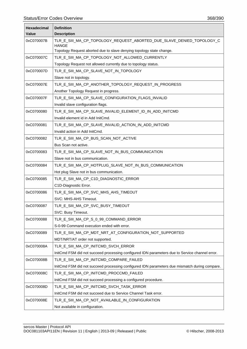
Status/Error Codes Overview 368/390
sercos Master | Protocol API DOC081103API11EN | Revision 11 | English | 2013-09 | Released | Public © Hilscher, 2008-2013
Hexadecimal
Value
Definition
Description
0xC070007B TLR_E_SIII_MA_CP_TOPOLOGY_REQUEST_ABORTED_DUE_SLAVE_DENIED_TOPOLOGY_CHANGE Topology Request aborted due to slave denying topology state change.
0xC070007C TLR_E_SIII_MA_CP_TOPOLOGY_NOT_ALLOWED_CURRENTLY
Topology Request not allowed currently due to topology status.
0xC070007D TLR_E_SIII_MA_CP_SLAVE_NOT_IN_TOPOLOGY
Slave not in topology.
0xC070007E TLR_E_SIII_MA_CP_ANOTHER_TOPOLOGY_REQUEST_IN_PROGRESS
Another Topology Request in progress.
0xC070007F TLR_E_SIII_MA_CP_SLAVE_CONFIGURATION_FLAGS_INVALID
Invalid slave configuration flags.
0xC0700080 TLR_E_SIII_MA_CP_SLAVE_INVALID_ELEMENT_ID_IN_ADD_INITCMD
Invalid element id in Add InitCmd.
0xC0700081 TLR_E_SIII_MA_CP_SLAVE_INVALID_ACTION_IN_ADD_INITCMD
Invalid action in Add InitCmd.
0xC0700082 TLR_E_SIII_MA_CP_BUS_SCAN_NOT_ACTIVE
Bus Scan not active.
0xC0700083 TLR_E_SIII_MA_CP_SLAVE_NOT_IN_BUS_COMMUNICATION
Slave not in bus communication.
0xC0700084 TLR_E_SIII_MA_CP_HOTPLUG_SLAVE_NOT_IN_BUS_COMMUNICATION
Hot plug Slave not in bus communication.
0xC0700085 TLR_E_SIII_MA_CP_C1D_DIAGNOSTIC_ERROR
C1D-Diagnostic Error.
0xC0700086 TLR_E_SIII_MA_CP_SVC_MHS_AHS_TIMEOUT
SVC: MHS-AHS Timeout.
0xC0700087 TLR_E_SIII_MA_CP_SVC_BUSY_TIMEOUT
SVC: Busy Timeout.
0xC0700088 TLR_E_SIII_MA_CP_S_0_99_COMMAND_ERROR
S-0-99 Command execution ended with error.
0xC0700089 TLR_E_SIII_MA_CP_MDT_NRT_AT_CONFIGURATION_NOT_SUPPORTED
MDT/NRT/AT order not supported.
0xC070008A TLR_E_SIII_MA_CP_INITCMD_SVCH_ERROR
InitCmd FSM did not succeed processing configured IDN parameters due to Service channel error.
0xC070008B TLR_E_SIII_MA_CP_INITCMD_COMPARE_FAILED
InitCmd FSM did not succeed processing configured IDN parameters due mismatch during compare.
0xC070008C TLR_E_SIII_MA_CP_INITCMD_PROCCMD_FAILED
InitCmd FSM did not succeed processing a configured procedure.
0xC070008D TLR_E_SIII_MA_CP_INITCMD_SVCH_TASK_ERROR
InitCmd FSM did not succeed due to Service Channel Task error.
0xC070008E TLR_E_SIII_MA_CP_NOT_AVAILABLE_IN_CONFIGURATION
Not available in configuration.
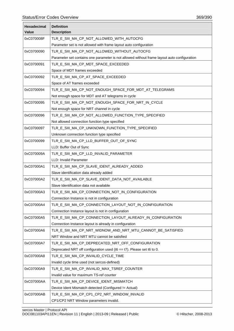
Status/Error Codes Overview 369/390
sercos Master | Protocol API DOC081103API11EN | Revision 11 | English | 2013-09 | Released | Public © Hilscher, 2008-2013
Hexadecimal
Value
Definition
Description
0xC070008F TLR_E_SIII_MA_CP_NOT_ALLOWED_WITH_AUTOCFG
Parameter set is not allowed with frame layout auto configuration
0xC0700090 TLR_E_SIII_MA_CP_NOT_ALLOWED_WITHOUT_AUTOCFG
Parameter set contains one parameter is not allowed without frame layout auto configuration
0xC0700091 TLR_E_SIII_MA_CP_MDT_SPACE_EXCEEDED
Space of MDT frames exceeded
0xC0700092 TLR_E_SIII_MA_CP_AT_SPACE_EXCEEDED
Space of AT frames exceeded
0xC0700094 TLR_E_SIII_MA_CP_NOT_ENOUGH_SPACE_FOR_MDT_AT_TELEGRAMS
Not enough space for MDT and AT telegrams in cycle
0xC0700095 TLR_E_SIII_MA_CP_NOT_ENOUGH_SPACE_FOR_NRT_IN_CYCLE
Not enough space for NRT channel in cycle
0xC0700096 TLR_E_SIII_MA_CP_NOT_ALLOWED_FUNCTION_TYPE_SPECIFIED
Not allowed connection function type specified
0xC0700097 TLR_E_SIII_MA_CP_UNKNOWN_FUNCTION_TYPE_SPECIFIED
Unknown connection function type specified
0xC0700099 TLR_E_SIII_MA_CP_LLD_BUFFER_OUT_OF_SYNC
LLD: Buffer Out of Sync
0xC070009A TLR_E_SIII_MA_CP_LLD_INVALID_PARAMETER
LLD: Invalid Parameter
0xC07000A1 TLR_E_SIII_MA_CP_SLAVE_IDENT_ALREADY_ADDED
Slave identification data already added
0xC07000A2 TLR_E_SIII_MA_CP_SLAVE_IDENT_DATA_NOT_AVAILABLE
Slave Identification data not available
0xC07000A3 TLR_E_SIII_MA_CP_CONNECTION_NOT_IN_CONFIGURATION
Connection Instance is not in configuration
0xC07000A4 TLR_E_SIII_MA_CP_CONNECTION_LAYOUT_NOT_IN_CONFIGURATION
Connection Instance layout is not in configuration
0xC07000A5 TLR_E_SIII_MA_CP_CONNECTION_LAYOUT_ALREADY_IN_CONFIGURATION
Connection Instance layout is already in configuration
0xC07000A6 TLR_E_SIII_MA_CP_NRT_WIDNOW_AND_NRT_MTU_CANNOT_BE_SATISFIED
NRT Window and NRT MTU cannot be satisfied
0xC07000A7 TLR_E_SIII_MA_CP_DEPRECATED_NRT_OFF_CONFIGURATION
Deprecated NRT off configuration used (t6 == t7). Please set t6 to 0.
0xC07000A8 TLR_E_SIII_MA_CP_INVALID_CYCLE_TIME
Invalid cycle time used (not sercos-defined)
0xC07000A9 TLR_E_SIII_MA_CP_INVALID_MAX_TSREF_COUNTER
Invalid value for maximum TS-ref counter
0xC07000AA TLR_E_SIII_MA_CP_DEVICE_IDENT_MISMATCH
Device Ident Mismatch detected (Configured != Actual)
0xC07000AB TLR_E_SIII_MA_CP_CP1_CP2_NRT_WINDOW_INVALID
CP1/CP2 NRT Window parameters invalid.
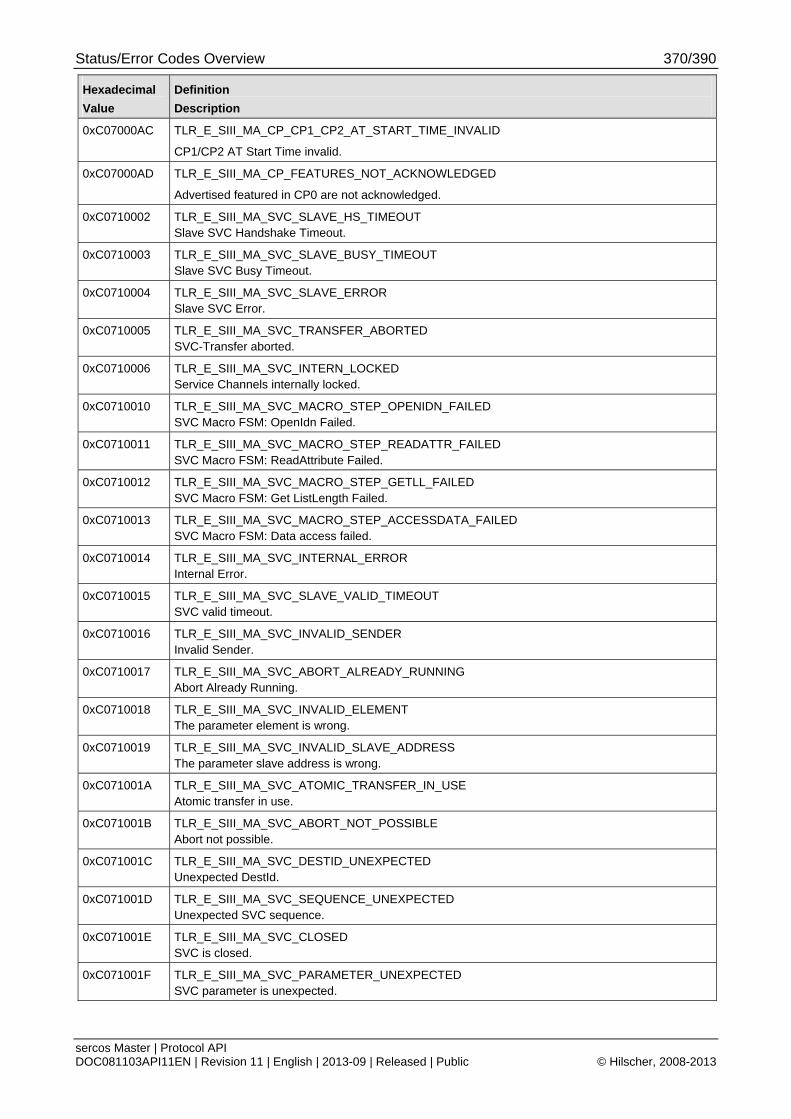
Status/Error Codes Overview 370/390
sercos Master | Protocol API DOC081103API11EN | Revision 11 | English | 2013-09 | Released | Public © Hilscher, 2008-2013
Hexadecimal
Value
Definition
Description
0xC07000AC TLR_E_SIII_MA_CP_CP1_CP2_AT_START_TIME_INVALID
CP1/CP2 AT Start Time invalid.
0xC07000AD TLR_E_SIII_MA_CP_FEATURES_NOT_ACKNOWLEDGED
Advertised featured in CP0 are not acknowledged.
0xC0710002 TLR_E_SIII_MA_SVC_SLAVE_HS_TIMEOUT Slave SVC Handshake Timeout.
0xC0710003 TLR_E_SIII_MA_SVC_SLAVE_BUSY_TIMEOUT Slave SVC Busy Timeout.
0xC0710004 TLR_E_SIII_MA_SVC_SLAVE_ERROR Slave SVC Error.
0xC0710005 TLR_E_SIII_MA_SVC_TRANSFER_ABORTED SVC-Transfer aborted.
0xC0710006 TLR_E_SIII_MA_SVC_INTERN_LOCKED Service Channels internally locked.
0xC0710010 TLR_E_SIII_MA_SVC_MACRO_STEP_OPENIDN_FAILED SVC Macro FSM: OpenIdn Failed.
0xC0710011 TLR_E_SIII_MA_SVC_MACRO_STEP_READATTR_FAILED SVC Macro FSM: ReadAttribute Failed.
0xC0710012 TLR_E_SIII_MA_SVC_MACRO_STEP_GETLL_FAILED SVC Macro FSM: Get ListLength Failed.
0xC0710013 TLR_E_SIII_MA_SVC_MACRO_STEP_ACCESSDATA_FAILED SVC Macro FSM: Data access failed.
0xC0710014 TLR_E_SIII_MA_SVC_INTERNAL_ERROR Internal Error.
0xC0710015 TLR_E_SIII_MA_SVC_SLAVE_VALID_TIMEOUT SVC valid timeout.
0xC0710016 TLR_E_SIII_MA_SVC_INVALID_SENDER Invalid Sender.
0xC0710017 TLR_E_SIII_MA_SVC_ABORT_ALREADY_RUNNING Abort Already Running.
0xC0710018 TLR_E_SIII_MA_SVC_INVALID_ELEMENT The parameter element is wrong.
0xC0710019 TLR_E_SIII_MA_SVC_INVALID_SLAVE_ADDRESS The parameter slave address is wrong.
0xC071001A TLR_E_SIII_MA_SVC_ATOMIC_TRANSFER_IN_USE Atomic transfer in use.
0xC071001B TLR_E_SIII_MA_SVC_ABORT_NOT_POSSIBLE Abort not possible.
0xC071001C TLR_E_SIII_MA_SVC_DESTID_UNEXPECTED Unexpected DestId.
0xC071001D TLR_E_SIII_MA_SVC_SEQUENCE_UNEXPECTED Unexpected SVC sequence.
0xC071001E TLR_E_SIII_MA_SVC_CLOSED SVC is closed.
0xC071001F TLR_E_SIII_MA_SVC_PARAMETER_UNEXPECTED SVC parameter is unexpected.
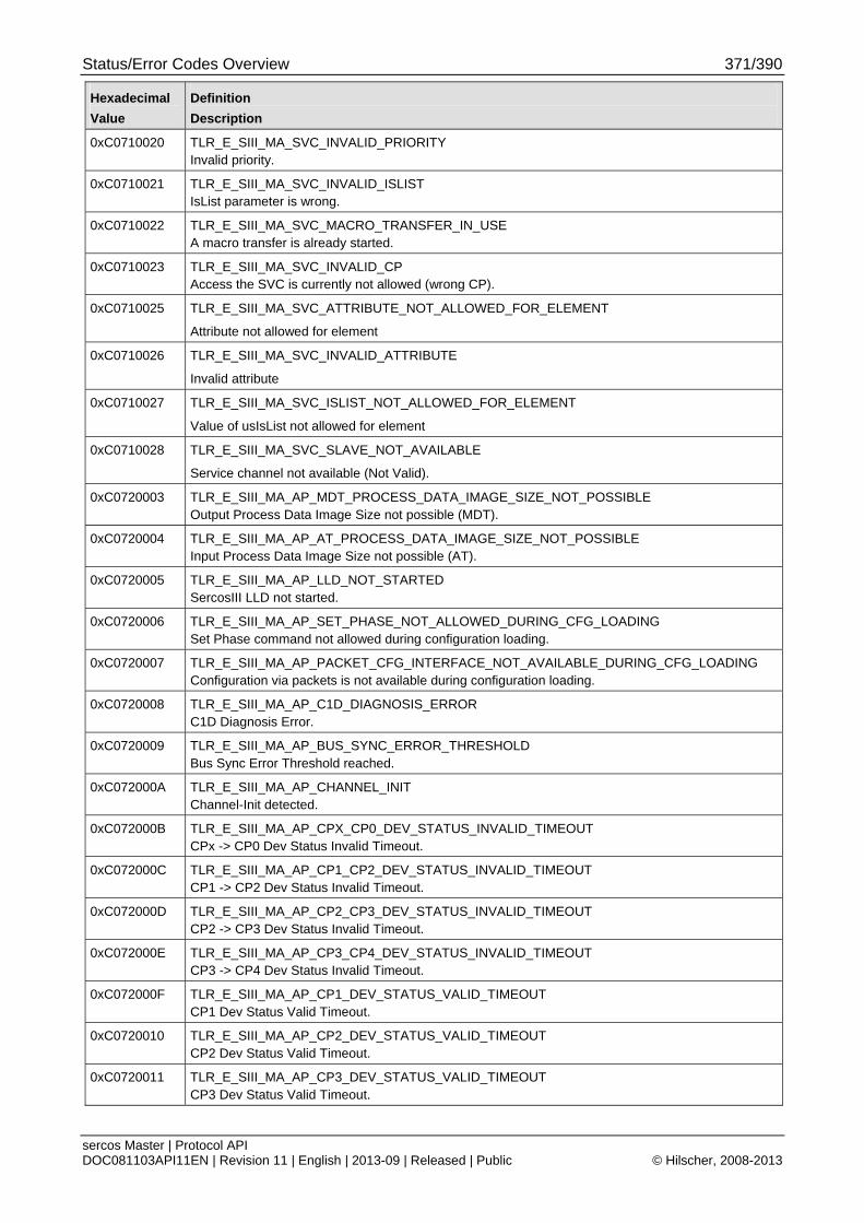
Status/Error Codes Overview 371/390
sercos Master | Protocol API DOC081103API11EN | Revision 11 | English | 2013-09 | Released | Public © Hilscher, 2008-2013
Hexadecimal
Value
Definition
Description
0xC0710020 TLR_E_SIII_MA_SVC_INVALID_PRIORITY Invalid priority.
0xC0710021 TLR_E_SIII_MA_SVC_INVALID_ISLIST IsList parameter is wrong.
0xC0710022 TLR_E_SIII_MA_SVC_MACRO_TRANSFER_IN_USE A macro transfer is already started.
0xC0710023 TLR_E_SIII_MA_SVC_INVALID_CP Access the SVC is currently not allowed (wrong CP).
0xC0710025 TLR_E_SIII_MA_SVC_ATTRIBUTE_NOT_ALLOWED_FOR_ELEMENT
Attribute not allowed for element
0xC0710026 TLR_E_SIII_MA_SVC_INVALID_ATTRIBUTE
Invalid attribute
0xC0710027 TLR_E_SIII_MA_SVC_ISLIST_NOT_ALLOWED_FOR_ELEMENT
Value of usIsList not allowed for element
0xC0710028 TLR_E_SIII_MA_SVC_SLAVE_NOT_AVAILABLE
Service channel not available (Not Valid).
0xC0720003 TLR_E_SIII_MA_AP_MDT_PROCESS_DATA_IMAGE_SIZE_NOT_POSSIBLE Output Process Data Image Size not possible (MDT).
0xC0720004 TLR_E_SIII_MA_AP_AT_PROCESS_DATA_IMAGE_SIZE_NOT_POSSIBLE Input Process Data Image Size not possible (AT).
0xC0720005 TLR_E_SIII_MA_AP_LLD_NOT_STARTED SercosIII LLD not started.
0xC0720006 TLR_E_SIII_MA_AP_SET_PHASE_NOT_ALLOWED_DURING_CFG_LOADING Set Phase command not allowed during configuration loading.
0xC0720007 TLR_E_SIII_MA_AP_PACKET_CFG_INTERFACE_NOT_AVAILABLE_DURING_CFG_LOADING Configuration via packets is not available during configuration loading.
0xC0720008 TLR_E_SIII_MA_AP_C1D_DIAGNOSIS_ERROR C1D Diagnosis Error.
0xC0720009 TLR_E_SIII_MA_AP_BUS_SYNC_ERROR_THRESHOLD Bus Sync Error Threshold reached.
0xC072000A TLR_E_SIII_MA_AP_CHANNEL_INIT Channel-Init detected.
0xC072000B TLR_E_SIII_MA_AP_CPX_CP0_DEV_STATUS_INVALID_TIMEOUT CPx -> CP0 Dev Status Invalid Timeout.
0xC072000C TLR_E_SIII_MA_AP_CP1_CP2_DEV_STATUS_INVALID_TIMEOUT CP1 -> CP2 Dev Status Invalid Timeout.
0xC072000D TLR_E_SIII_MA_AP_CP2_CP3_DEV_STATUS_INVALID_TIMEOUT CP2 -> CP3 Dev Status Invalid Timeout.
0xC072000E TLR_E_SIII_MA_AP_CP3_CP4_DEV_STATUS_INVALID_TIMEOUT CP3 -> CP4 Dev Status Invalid Timeout.
0xC072000F TLR_E_SIII_MA_AP_CP1_DEV_STATUS_VALID_TIMEOUT CP1 Dev Status Valid Timeout.
0xC0720010 TLR_E_SIII_MA_AP_CP2_DEV_STATUS_VALID_TIMEOUT CP2 Dev Status Valid Timeout.
0xC0720011 TLR_E_SIII_MA_AP_CP3_DEV_STATUS_VALID_TIMEOUT CP3 Dev Status Valid Timeout.
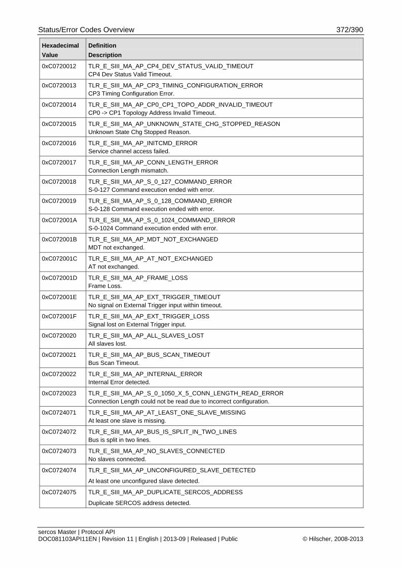
Status/Error Codes Overview 372/390
sercos Master | Protocol API DOC081103API11EN | Revision 11 | English | 2013-09 | Released | Public © Hilscher, 2008-2013
Hexadecimal
Value
Definition
Description
0xC0720012 TLR_E_SIII_MA_AP_CP4_DEV_STATUS_VALID_TIMEOUT CP4 Dev Status Valid Timeout.
0xC0720013 TLR_E_SIII_MA_AP_CP3_TIMING_CONFIGURATION_ERROR CP3 Timing Configuration Error.
0xC0720014 TLR_E_SIII_MA_AP_CP0_CP1_TOPO_ADDR_INVALID_TIMEOUT CP0 -> CP1 Topology Address Invalid Timeout.
0xC0720015 TLR_E_SIII_MA_AP_UNKNOWN_STATE_CHG_STOPPED_REASON Unknown State Chg Stopped Reason.
0xC0720016 TLR_E_SIII_MA_AP_INITCMD_ERROR Service channel access failed.
0xC0720017 TLR_E_SIII_MA_AP_CONN_LENGTH_ERROR Connection Length mismatch.
0xC0720018 TLR_E_SIII_MA_AP_S_0_127_COMMAND_ERROR S-0-127 Command execution ended with error.
0xC0720019 TLR_E_SIII_MA_AP_S_0_128_COMMAND_ERROR S-0-128 Command execution ended with error.
0xC072001A TLR_E_SIII_MA_AP_S_0_1024_COMMAND_ERROR S-0-1024 Command execution ended with error.
0xC072001B TLR_E_SIII_MA_AP_MDT_NOT_EXCHANGED MDT not exchanged.
0xC072001C TLR_E_SIII_MA_AP_AT_NOT_EXCHANGED AT not exchanged.
0xC072001D TLR_E_SIII_MA_AP_FRAME_LOSS Frame Loss.
0xC072001E TLR_E_SIII_MA_AP_EXT_TRIGGER_TIMEOUT No signal on External Trigger input within timeout.
0xC072001F TLR_E_SIII_MA_AP_EXT_TRIGGER_LOSS Signal lost on External Trigger input.
0xC0720020 TLR_E_SIII_MA_AP_ALL_SLAVES_LOST All slaves lost.
0xC0720021 TLR_E_SIII_MA_AP_BUS_SCAN_TIMEOUT Bus Scan Timeout.
0xC0720022 TLR_E_SIII_MA_AP_INTERNAL_ERROR Internal Error detected.
0xC0720023 TLR_E_SIII_MA_AP_S_0_1050_X_5_CONN_LENGTH_READ_ERROR Connection Length could not be read due to incorrect configuration.
0xC0724071 TLR_E_SIII_MA_AP_AT_LEAST_ONE_SLAVE_MISSING At least one slave is missing.
0xC0724072 TLR_E_SIII_MA_AP_BUS_IS_SPLIT_IN_TWO_LINES Bus is split in two lines.
0xC0724073 TLR_E_SIII_MA_AP_NO_SLAVES_CONNECTED No slaves connected.
0xC0724074 TLR_E_SIII_MA_AP_UNCONFIGURED_SLAVE_DETECTED
At least one unconfigured slave detected.
0xC0724075 TLR_E_SIII_MA_AP_DUPLICATE_SERCOS_ADDRESS
Duplicate SERCOS address detected.
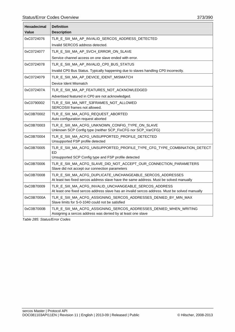
Status/Error Codes Overview 373/390
sercos Master | Protocol API DOC081103API11EN | Revision 11 | English | 2013-09 | Released | Public © Hilscher, 2008-2013
Hexadecimal
Value
Definition
Description
0xC0724076 TLR_E_SIII_MA_AP_INVALID_SERCOS_ADDRESS_DETECTED
Invalid SERCOS address detected.
0xC0724077 TLR_E_SIII_MA_AP_SVCH_ERROR_ON_SLAVE
Service channel access on one slave ended with error.
0xC0724078 TLR_E_SIII_MA_AP_INVALID_CP0_BUS_STATUS
Invalid CP0 Bus Status. Typically happening due to slaves handling CP0 incorrectly.
0xC0724079 TLR_E_SIII_MA_AP_DEVICE_IDENT_MISMATCH
Device Ident Mismatch
0xC072407A TLR_E_SIII_MA_AP_FEATURES_NOT_ACKNOWLEDGED
Advertised featured in CP0 are not acknowledged.
0xC0790002 TLR_E_SIII_MA_NRT_S3FRAMES_NOT_ALLOWED SERCOSIII frames not allowed.
0xC0B70002 TLR_E_SIII_MA_ACFG_REQUEST_ABORTED Auto configuration request aborted
0xC0B70003 TLR_E_SIII_MA_ACFG_UNKNOWN_CONFIG_TYPE_ON_SLAVE Unknown SCP Config type (neither SCP_FixCFG nor SCP_VarCFG)
0xC0B70004 TLR_E_SIII_MA_ACFG_UNSUPPORTED_PROFILE_DETECTED Unsupported FSP profile detected
0xC0B70005 TLR_E_SIII_MA_ACFG_UNSUPPORTED_PROFILE_TYPE_CFG_TYPE_COMBINATION_DETECTED Unsupported SCP Config type and FSP profile detected
0xC0B70006 TLR_E_SIII_MA_ACFG_SLAVE_DID_NOT_ACCEPT_OUR_CONNECTION_PARAMETERS Slave did not accept our connection parameters
0xC0B70008 TLR_E_SIII_MA_ACFG_DUPLICATE_UNCHANGEABLE_SERCOS_ADDRESSES At least two fixed sercos address slave have the same address. Must be solved manually
0xC0B70009 TLR_E_SIII_MA_ACFG_INVALID_UNCHANGEABLE_SERCOS_ADDRESS At least one fixed sercos address slave has an invalid sercos address. Must be solved manually
0xC0B7000A TLR_E_SIII_MA_ACFG_ASSIGNING_SERCOS_ADDRESSES_DENIED_BY_MIN_MAX Slave limits for S-0-1040 could not be satisfied
0xC0B7000B TLR_E_SIII_MA_ACFG_ASSIGNING_SERCOS_ADDRESSES_DENIED_WHEN_WRITING Assigning a sercos address was denied by at least one slave
Table 285: Status/Error Codes
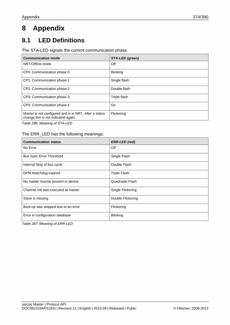
Appendix 374/390
sercos Master | Protocol API DOC081103API11EN | Revision 11 | English | 2013-09 | Released | Public © Hilscher, 2008-2013
8 Appendix
8.1 LED Definitions
The STA-LED signals the current communication phase.
Communication mode STA-LED (green)
NRT/Offline-mode Off
CP0: Communication phase 0 Blinking
CP1: Communication phase 1 Single flash
CP2: Communication phase 2 Double flash
CP3: Communication phase 3 Triple flash
CP4: Communication phase 4 On
Master is not configured and is in NRT. After a status change this is not indicated again.
Flickering
Table 286: Meaning of STA-LED
The ERR_LED has the following meanings:
Communication status ERR-LED (red)
No Error Off
Bus Sync Error Threshold Single Flash
Internal Stop of bus cycle Double Flash
DPM Watchdog expired Triple Flash
No master license present in device Quadruple Flash
Channel Init was executed at master Single Flickering
Slave is missing Double Flickering
Boot-up was stopped due to an error Flickering
Error in configuration database Blinking
Table 287: Meaning of ERR-LED
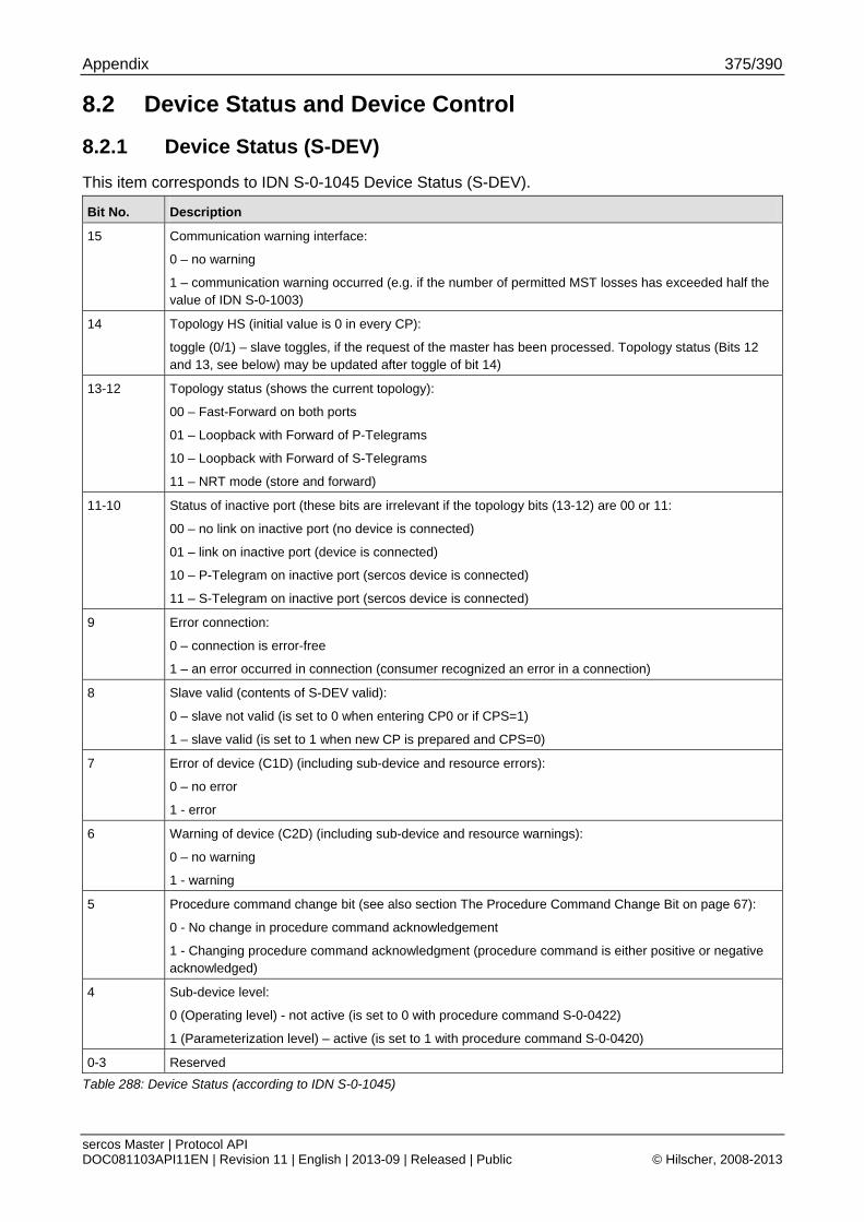
Appendix 375/390
sercos Master | Protocol API DOC081103API11EN | Revision 11 | English | 2013-09 | Released | Public © Hilscher, 2008-2013
8.2 Device Status and Device Control
8.2.1 Device Status (S-DEV)
This item corresponds to IDN S-0-1045 Device Status (S-DEV).
Bit No. Description
15 Communication warning interface:
0 – no warning
1 – communication warning occurred (e.g. if the number of permitted MST losses has exceeded half the value of IDN S-0-1003)
14 Topology HS (initial value is 0 in every CP):
toggle (0/1) – slave toggles, if the request of the master has been processed. Topology status (Bits 12 and 13, see below) may be updated after toggle of bit 14)
13-12 Topology status (shows the current topology):
00 – Fast-Forward on both ports
01 – Loopback with Forward of P-Telegrams
10 – Loopback with Forward of S-Telegrams
11 – NRT mode (store and forward)
11-10 Status of inactive port (these bits are irrelevant if the topology bits (13-12) are 00 or 11:
00 – no link on inactive port (no device is connected)
01 – link on inactive port (device is connected)
10 – P-Telegram on inactive port (sercos device is connected)
11 – S-Telegram on inactive port (sercos device is connected)
9 Error connection:
0 – connection is error-free
1 – an error occurred in connection (consumer recognized an error in a connection)
8 Slave valid (contents of S-DEV valid):
0 – slave not valid (is set to 0 when entering CP0 or if CPS=1)
1 – slave valid (is set to 1 when new CP is prepared and CPS=0)
7 Error of device (C1D) (including sub-device and resource errors):
0 – no error
1 - error
6 Warning of device (C2D) (including sub-device and resource warnings):
0 – no warning
1 - warning
5 Procedure command change bit (see also section The Procedure Command Change Bit on page 67):
0 - No change in procedure command acknowledgement
1 - Changing procedure command acknowledgment (procedure command is either positive or negative acknowledged)
4 Sub-device level:
0 (Operating level) - not active (is set to 0 with procedure command S-0-0422)
1 (Parameterization level) – active (is set to 1 with procedure command S-0-0420)
0-3 Reserved
Table 288: Device Status (according to IDN S-0-1045)
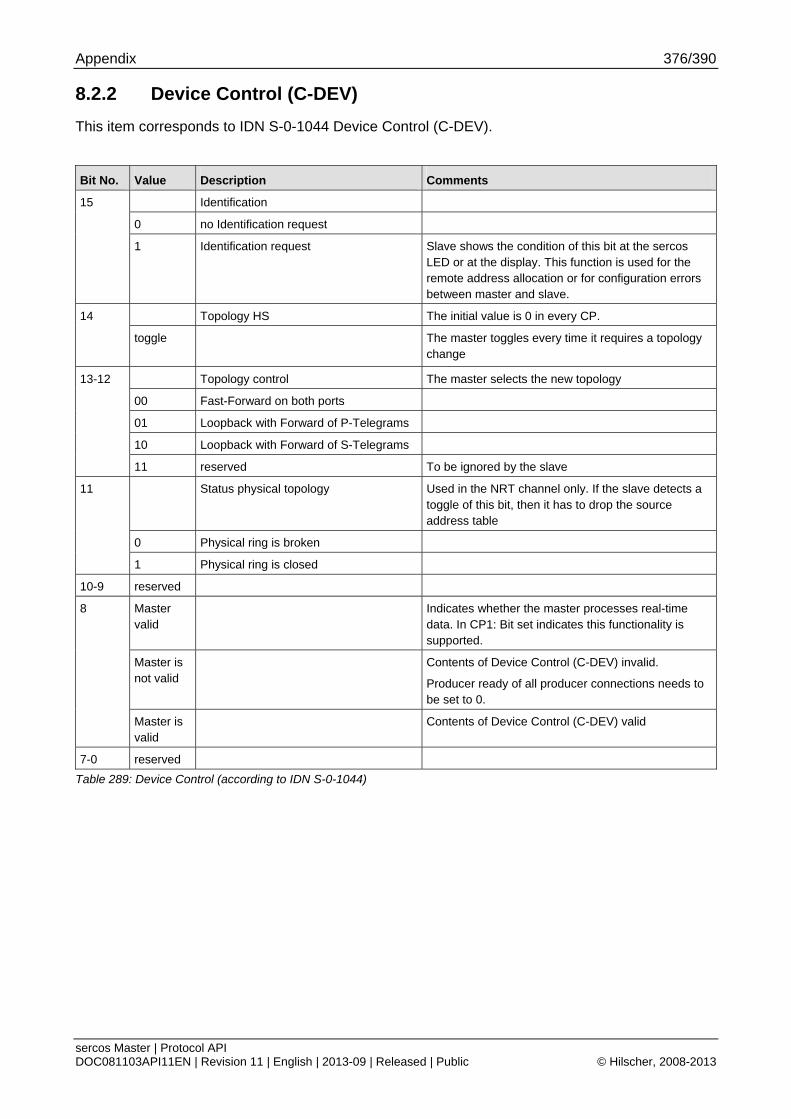
Appendix 376/390
sercos Master | Protocol API DOC081103API11EN | Revision 11 | English | 2013-09 | Released | Public © Hilscher, 2008-2013
8.2.2 Device Control (C-DEV)
This item corresponds to IDN S-0-1044 Device Control (C-DEV).
Bit No. Value Description Comments
Identification
0 no Identification request
15
1 Identification request Slave shows the condition of this bit at the sercos LED or at the display. This function is used for the remote address allocation or for configuration errors between master and slave.
Topology HS The initial value is 0 in every CP. 14
toggle The master toggles every time it requires a topology change
Topology control The master selects the new topology
00 Fast-Forward on both ports
01 Loopback with Forward of P-Telegrams
10 Loopback with Forward of S-Telegrams
13-12
11 reserved To be ignored by the slave
Status physical topology Used in the NRT channel only. If the slave detects a toggle of this bit, then it has to drop the source address table
0 Physical ring is broken
11
1 Physical ring is closed
10-9 reserved
Master valid
Indicates whether the master processes real-time data. In CP1: Bit set indicates this functionality is supported.
Master is not valid
Contents of Device Control (C-DEV) invalid.
Producer ready of all producer connections needs to be set to 0.
8
Master is valid
Contents of Device Control (C-DEV) valid
7-0 reserved
Table 289: Device Control (according to IDN S-0-1044)
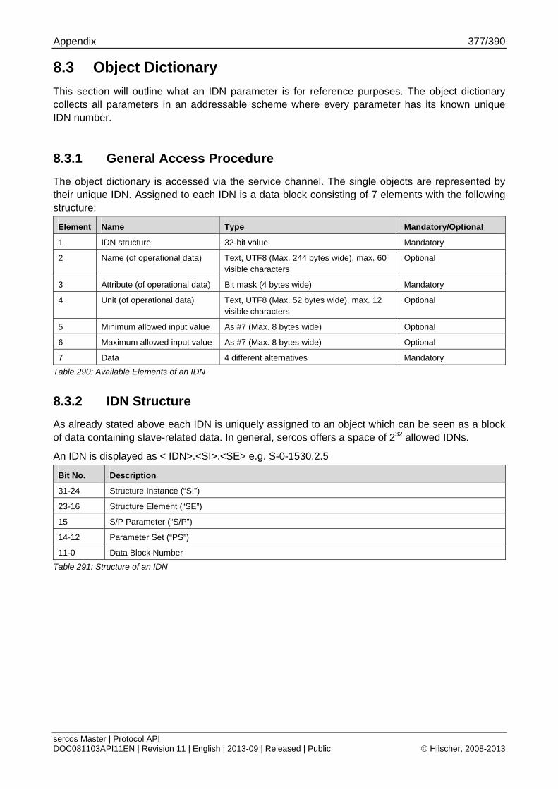
Appendix 377/390
sercos Master | Protocol API DOC081103API11EN | Revision 11 | English | 2013-09 | Released | Public © Hilscher, 2008-2013
8.3 Object Dictionary
This section will outline what an IDN parameter is for reference purposes. The object dictionary collects all parameters in an addressable scheme where every parameter has its known unique IDN number.
8.3.1 General Access Procedure
The object dictionary is accessed via the service channel. The single objects are represented by their unique IDN. Assigned to each IDN is a data block consisting of 7 elements with the following structure:
Element Name Type Mandatory/Optional
1 IDN structure 32-bit value Mandatory
2 Name (of operational data) Text, UTF8 (Max. 244 bytes wide), max. 60 visible characters
Optional
3 Attribute (of operational data) Bit mask (4 bytes wide) Mandatory
4 Unit (of operational data) Text, UTF8 (Max. 52 bytes wide), max. 12 visible characters
Optional
5 Minimum allowed input value As #7 (Max. 8 bytes wide) Optional
6 Maximum allowed input value As #7 (Max. 8 bytes wide) Optional
7 Data 4 different alternatives Mandatory
Table 290: Available Elements of an IDN
8.3.2 IDN Structure
As already stated above each IDN is uniquely assigned to an object which can be seen as a block of data containing slave-related data. In general, sercos offers a space of 232 allowed IDNs.
An IDN is displayed as < IDN>.<SI>.<SE> e.g. S-0-1530.2.5
Bit No. Description
31-24 Structure Instance (“SI”)
23-16 Structure Element (“SE”)
15 S/P Parameter (“S/P”)
14-12 Parameter Set (“PS”)
11-0 Data Block Number
Table 291: Structure of an IDN
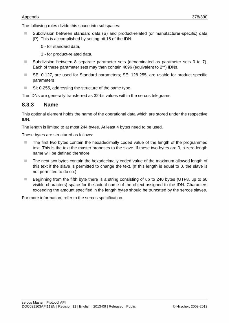
Appendix 378/390
sercos Master | Protocol API DOC081103API11EN | Revision 11 | English | 2013-09 | Released | Public © Hilscher, 2008-2013
The following rules divide this space into subspaces:
Subdivision between standard data (S) and product-related (or manufacturer-specific) data (P). This is accomplished by setting bit 15 of the IDN:
0 - for standard data,
1 - for product-related data.
Subdivision between 8 separate parameter sets (denominated as parameter sets 0 to 7). Each of these parameter sets may then contain 4096 (equivalent to 212) IDNs.
SE: 0-127, are used for Standard parameters; SE: 128-255, are usable for product specific parameters
SI: 0-255, addressing the structure of the same type
The IDNs are generally transferred as 32-bit values within the sercos telegrams
8.3.3 Name
This optional element holds the name of the operational data which are stored under the respective IDN.
The length is limited to at most 244 bytes. At least 4 bytes need to be used.
These bytes are structured as follows:
The first two bytes contain the hexadecimally coded value of the length of the programmed text. This is the text the master proposes to the slave. If these two bytes are 0, a zero-length name will be defined therefore.
The next two bytes contain the hexadecimally coded value of the maximum allowed length of this text if the slave is permitted to change the text. (If this length is equal to 0, the slave is not permitted to do so.)
Beginning from the fifth byte there is a string consisting of up to 240 bytes (UTF8, up to 60 visible characters) space for the actual name of the object assigned to the IDN. Characters exceeding the amount specified in the length bytes should be truncated by the sercos slaves.
For more information, refer to the sercos specification.
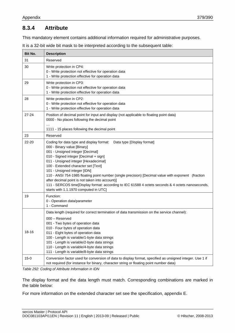
Appendix 379/390
sercos Master | Protocol API DOC081103API11EN | Revision 11 | English | 2013-09 | Released | Public © Hilscher, 2008-2013
8.3.4 Attribute
This mandatory element contains additional information required for administrative purposes.
It is a 32-bit wide bit mask to be interpreted according to the subsequent table:
Bit No. Description
31 Reserved
30 Write protection in CP4: 0 - Write protection not effective for operation data 1 - Write protection effective for operation data
29 Write protection in CP3: 0 - Write protection not effective for operation data 1 - Write protection effective for operation data
28 Write protection in CP2: 0 - Write protection not effective for operation data 1 - Write protection effective for operation data
27-24 Position of decimal point for input and display (not applicable to floating point data) 0000 - No places following the decimal point … 1111 - 15 places following the decimal point
23 Reserved
22-20 Coding for data type and display format: Data type [Display format] 000 - Binary value [Binary] 001 - Unsigned integer [Decimal] 010 - Signed integer [Decimal + sign] 011 - Unsigned integer [Hexadecimal] 100 - Extended character set [Text] 101 - Unsigned integer [IDN] 110 - ANSI 754-1985 floating point number (single precision) [Decimal value with exponent (fraction after decimal point is not taken into account)] 111 - SERCOS time[Display format: according to IEC 61588 4 octets seconds & 4 octets nanoseconds, starts with 1.1.1970 computed in UTC]
19 Function: 0 - Operation data/parameter 1 - Command
18-16
Data length (required for correct termination of data transmission on the service channel):
000 – Reserved 001 - Two bytes of operation data 010 - Four bytes of operation data 011 - Eight bytes of operation data 100 - Length is variable/1-byte data strings 101 - Length is variable/2-byte data strings 110 - Length is variable/4-byte data strings 111 - Length is variable/8-byte data strings
15-0 Conversion factor used for conversion of data to display format, specified as unsigned integer. Use 1 if not required (for instance for binary, character string or floating point number data)
Table 292: Coding of Attribute Information in IDN
The display format and the data length must match. Corresponding combinations are marked in the table below:
For more information on the extended character set see the specification, appendix E.
Appendix 380/390
sercos Master | Protocol API DOC081103API11EN | Revision 11 | English | 2013-09 | Released | Public © Hilscher, 2008-2013
8.3.5 Unit
This optional element holds the name of unit to be applied to the operational data which are stored under the respective IDN.
The length is limited to at most 52 bytes. At least 4 bytes need to be used.
These bytes are structured as follows:
The first two bytes contain the hexadecimal coded value of the length of the programmed text. This is the text the master proposes to the slave. If these two bytes are 0, a zero-length name will be defined therefore.
The next two bytes contain the hexadecimal coded value of the maximum allowed length of this text if the slave is permitted to change the text. (If this length is equal to 0, the slave is not permitted to do so.)
Beginning from the fifth byte there is a string consisting of up to 48 bytes (UTF8, up to 12 visible characters) space for the actual unit of the object assigned to the IDN. Characters exceeding the amount specified in the length bytes should be truncated by the sercos slaves.
When the data type is either binary or character string, the data has no unit. For more information, refer to the sercos specification.
8.3.6 Minimum / Maximum
This optional element holds the minimum or maximum value allowed for the operational data which are stored under the respective IDN. Lower or higher values respective cannot be processed by the slave, i.e. when a write request occurs with a lower or higher value, the original value will not be changed.
This element is not applicable in the following cases:
Working with binary numbers
Working with character strings
Operation data have variable length
Note: Maximum can also be used for binary data according to the sercos standard, set bits are supported by the slave.
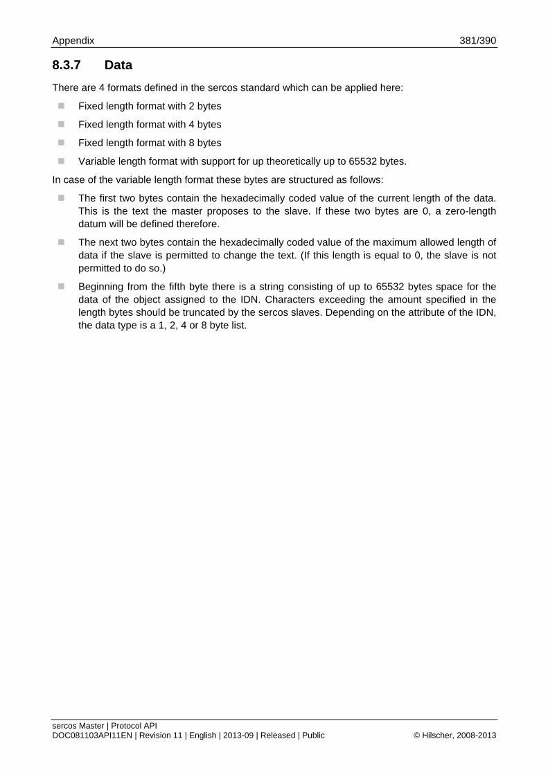
Appendix 381/390
sercos Master | Protocol API DOC081103API11EN | Revision 11 | English | 2013-09 | Released | Public © Hilscher, 2008-2013
8.3.7 Data
There are 4 formats defined in the sercos standard which can be applied here:
Fixed length format with 2 bytes
Fixed length format with 4 bytes
Fixed length format with 8 bytes
Variable length format with support for up theoretically up to 65532 bytes.
In case of the variable length format these bytes are structured as follows:
The first two bytes contain the hexadecimally coded value of the current length of the data. This is the text the master proposes to the slave. If these two bytes are 0, a zero-length datum will be defined therefore.
The next two bytes contain the hexadecimally coded value of the maximum allowed length of data if the slave is permitted to change the text. (If this length is equal to 0, the slave is not permitted to do so.)
Beginning from the fifth byte there is a string consisting of up to 65532 bytes space for the data of the object assigned to the IDN. Characters exceeding the amount specified in the length bytes should be truncated by the sercos slaves. Depending on the attribute of the IDN, the data type is a 1, 2, 4 or 8 byte list.

Appendix 382/390
sercos Master | Protocol API DOC081103API11EN | Revision 11 | English | 2013-09 | Released | Public © Hilscher, 2008-2013
8.3.8 sercos Service Channel Error Codes
The following table summarizes the service channel errors.
Error code Description
0x0nnn General error
0x0000 No error in the service channel
0x0001 Service channel not open
0x0009 Invalid access to closing the service channel
0x1nnn Element 1 (Ident number)
0x1001 No IDN
0x1009 Invalid access to element 1
0x2nnn Element 2 (Name)
0x2001 No name
0x2002 Name transmission too short
0x2003 Name transmission too long
0x2004 Name cannot be changed (read only)
0x2005 Name is write-protected at this time
0x3nnn Element 3 (Attribute)
0x3002 Attribute transmission too short
0x3003 Attribute transmission too long
0x3004 Attribute cannot be changed (read only)
0x3005 Attribute is write-protected at this time
0x4nnn Element 4 (Unit)
0x4001 No units
0x4002 Unit transmission too short
0x4003 Unit transmission too long
0x4004 Unit cannot be changed (read only)
0x4005 Unit is write-protected at this time
0x5nnn Element 5 (Minimum input value)
0x5001 No minimum input value
0x5002 Minimum input value transmission too short
0x5003 Minimum input value transmission too long
0x5004 Minimum input value cannot be changed (read only)
0x5005 Minimum input value is write-protected at this time
0x6nnn Element 6 (Maximum input value)
0x6001 No maximum input value
0x6002 Maximum input value transmission too short
0x6003 Maximum input value transmission too long
0x6004 Maximum input value cannot be changed (read only)
0x6005 Maximum input value is write-protected at this time
0x7nnn Element 7 (Operation data)
0x7002 Operation data transmission too short
0x7003 Operation data transmission too long
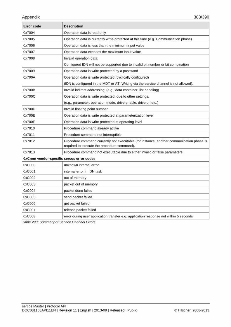
Appendix 383/390
sercos Master | Protocol API DOC081103API11EN | Revision 11 | English | 2013-09 | Released | Public © Hilscher, 2008-2013
Error code Description
0x7004 Operation data is read only
0x7005 Operation data is currently write-protected at this time (e.g. Communication phase)
0x7006 Operation data is less than the minimum input value
0x7007 Operation data exceeds the maximum input value
0x7008 Invalid operation data:
Configured IDN will not be supported due to invalid bit number or bit combination
0x7009 Operation data is write protected by a password
0x700A Operation data is write protected (cyclically configured)
(IDN is configured in the MDT or AT. Writing via the service channel is not allowed).
0x700B Invalid indirect addressing: (e.g., data container, list handling)
0x700C Operation data is write protected, due to other settings.
(e.g., parameter, operation mode, drive enable, drive on etc.)
0x700D Invalid floating point number
0x700E Operation data is write protected at parameterization level
0x700F Operation data is write protected at operating level
0x7010 Procedure command already active
0x7011 Procedure command not interruptible
0x7012 Procedure command currently not executable (for instance, another communication phase is required to execute the procedure command).
0x7013 Procedure command not executable due to either invalid or false parameters
0xCnnn vendor-specific sercos error codes
0xC000 unknown internal error
0xC001 internal error in IDN task
0xC002 out of memory
0xC003 packet out of memory
0xC004 packet done failed
0xC005 send packet failed
0xC006 get packet failed
0xC007 release packet failed
0xC008 error during user application transfer e.g. application response not within 5 seconds
Table 293: Summary of Service Channel Errors
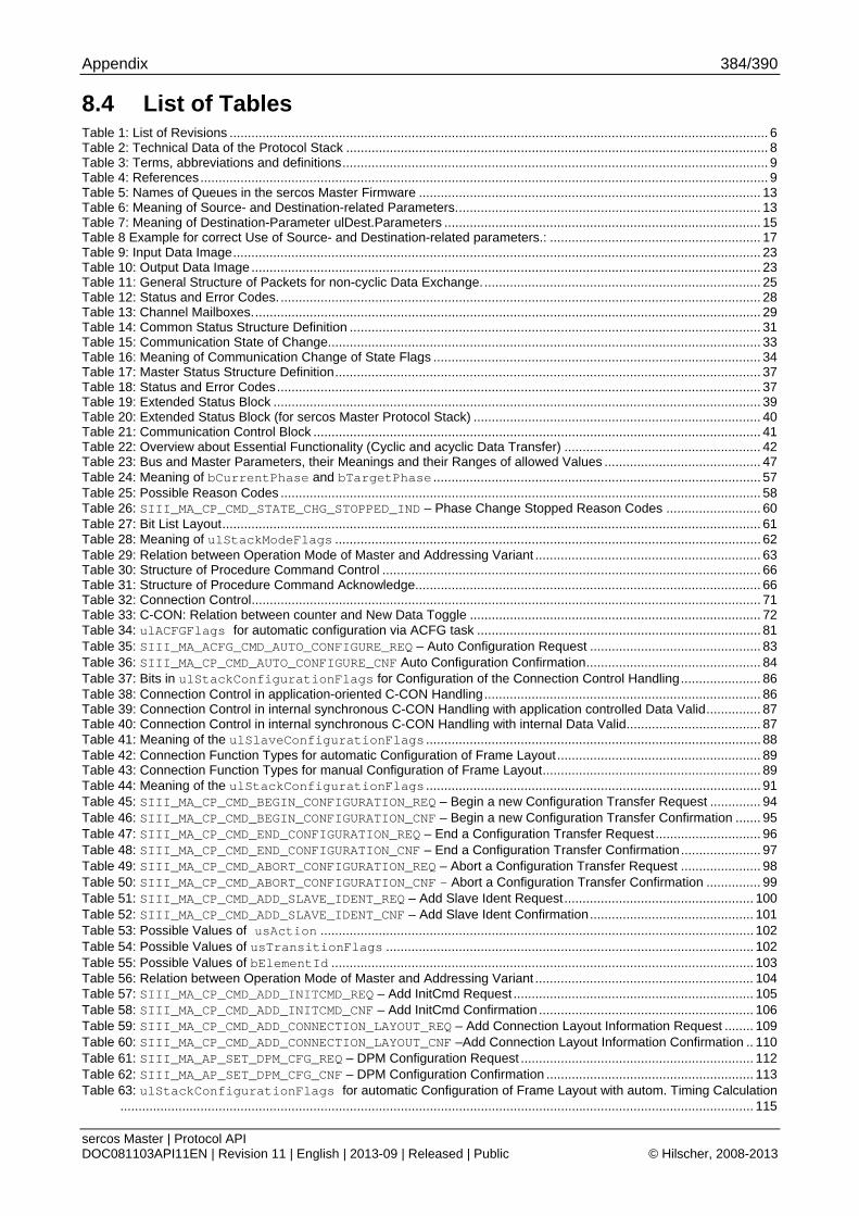
Appendix 384/390
sercos Master | Protocol API DOC081103API11EN | Revision 11 | English | 2013-09 | Released | Public © Hilscher, 2008-2013
8.4 List of Tables Table 1: List of Revisions .................................................................................................................................................... 6 Table 2: Technical Data of the Protocol Stack .................................................................................................................... 8 Table 3: Terms, abbreviations and definitions..................................................................................................................... 9 Table 4: References............................................................................................................................................................ 9 Table 5: Names of Queues in the sercos Master Firmware .............................................................................................. 13 Table 6: Meaning of Source- and Destination-related Parameters.................................................................................... 13 Table 7: Meaning of Destination-Parameter ulDest.Parameters ....................................................................................... 15 Table 8 Example for correct Use of Source- and Destination-related parameters.: .......................................................... 17 Table 9: Input Data Image................................................................................................................................................. 23 Table 10: Output Data Image ............................................................................................................................................ 23 Table 11: General Structure of Packets for non-cyclic Data Exchange............................................................................. 25 Table 12: Status and Error Codes..................................................................................................................................... 28 Table 13: Channel Mailboxes............................................................................................................................................ 29 Table 14: Common Status Structure Definition ................................................................................................................. 31 Table 15: Communication State of Change....................................................................................................................... 33 Table 16: Meaning of Communication Change of State Flags .......................................................................................... 34 Table 17: Master Status Structure Definition..................................................................................................................... 37 Table 18: Status and Error Codes..................................................................................................................................... 37 Table 19: Extended Status Block ...................................................................................................................................... 39 Table 20: Extended Status Block (for sercos Master Protocol Stack) ............................................................................... 40 Table 21: Communication Control Block ........................................................................................................................... 41 Table 22: Overview about Essential Functionality (Cyclic and acyclic Data Transfer) ...................................................... 42 Table 23: Bus and Master Parameters, their Meanings and their Ranges of allowed Values ........................................... 47 Table 24: Meaning of bCurrentPhase and bTargetPhase .......................................................................................... 57 Table 25: Possible Reason Codes .................................................................................................................................... 58 Table 26: SIII_MA_CP_CMD_STATE_CHG_STOPPED_IND – Phase Change Stopped Reason Codes .......................... 60 Table 27: Bit List Layout.................................................................................................................................................... 61 Table 28: Meaning of ulStackModeFlags ..................................................................................................................... 62 Table 29: Relation between Operation Mode of Master and Addressing Variant .............................................................. 63 Table 30: Structure of Procedure Command Control ........................................................................................................ 66 Table 31: Structure of Procedure Command Acknowledge............................................................................................... 66 Table 32: Connection Control............................................................................................................................................ 71 Table 33: C-CON: Relation between counter and New Data Toggle ................................................................................ 72 Table 34: ulACFGFlags for automatic configuration via ACFG task .............................................................................. 81 Table 35: SIII_MA_ACFG_CMD_AUTO_CONFIGURE_REQ – Auto Configuration Request ............................................... 83 Table 36: SIII_MA_CP_CMD_AUTO_CONFIGURE_CNF Auto Configuration Confirmation................................................ 84 Table 37: Bits in ulStackConfigurationFlags for Configuration of the Connection Control Handling...................... 86 Table 38: Connection Control in application-oriented C-CON Handling............................................................................ 86 Table 39: Connection Control in internal synchronous C-CON Handling with application controlled Data Valid............... 87 Table 40: Connection Control in internal synchronous C-CON Handling with internal Data Valid..................................... 87 Table 41: Meaning of the ulSlaveConfigurationFlags ............................................................................................ 88 Table 42: Connection Function Types for automatic Configuration of Frame Layout........................................................ 89 Table 43: Connection Function Types for manual Configuration of Frame Layout............................................................ 89 Table 44: Meaning of the ulStackConfigurationFlags ............................................................................................ 91 Table 45: SIII_MA_CP_CMD_BEGIN_CONFIGURATION_REQ – Begin a new Configuration Transfer Request .............. 94 Table 46: SIII_MA_CP_CMD_BEGIN_CONFIGURATION_CNF – Begin a new Configuration Transfer Confirmation ....... 95 Table 47: SIII_MA_CP_CMD_END_CONFIGURATION_REQ – End a Configuration Transfer Request ............................. 96 Table 48: SIII_MA_CP_CMD_END_CONFIGURATION_CNF – End a Configuration Transfer Confirmation...................... 97 Table 49: SIII_MA_CP_CMD_ABORT_CONFIGURATION_REQ – Abort a Configuration Transfer Request ...................... 98 Table 50: SIII_MA_CP_CMD_ABORT_CONFIGURATION_CNF – Abort a Configuration Transfer Confirmation ............... 99 Table 51: SIII_MA_CP_CMD_ADD_SLAVE_IDENT_REQ – Add Slave Ident Request.................................................... 100 Table 52: SIII_MA_CP_CMD_ADD_SLAVE_IDENT_CNF – Add Slave Ident Confirmation............................................. 101 Table 53: Possible Values of usAction ....................................................................................................................... 102 Table 54: Possible Values of usTransitionFlags ..................................................................................................... 102 Table 55: Possible Values of bElementId .................................................................................................................... 103 Table 56: Relation between Operation Mode of Master and Addressing Variant ............................................................ 104 Table 57: SIII_MA_CP_CMD_ADD_INITCMD_REQ – Add InitCmd Request .................................................................. 105 Table 58: SIII_MA_CP_CMD_ADD_INITCMD_CNF – Add InitCmd Confirmation ........................................................... 106 Table 59: SIII_MA_CP_CMD_ADD_CONNECTION_LAYOUT_REQ – Add Connection Layout Information Request ........ 109 Table 60: SIII_MA_CP_CMD_ADD_CONNECTION_LAYOUT_CNF –Add Connection Layout Information Confirmation .. 110 Table 61: SIII_MA_AP_SET_DPM_CFG_REQ – DPM Configuration Request ................................................................ 112 Table 62: SIII_MA_AP_SET_DPM_CFG_CNF – DPM Configuration Confirmation ......................................................... 113 Table 63: ulStackConfigurationFlags for automatic Configuration of Frame Layout with autom. Timing Calculation
.............................................................................................................................................................................. 115
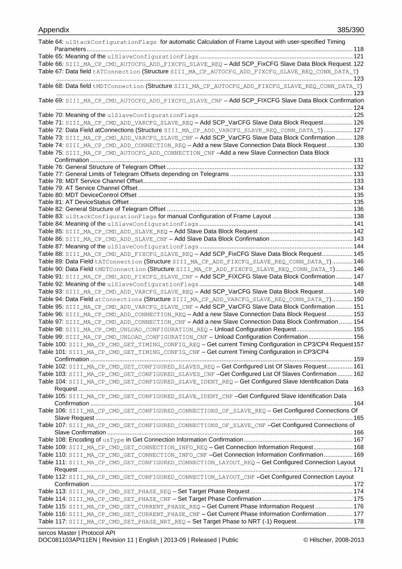
Appendix 385/390
sercos Master | Protocol API DOC081103API11EN | Revision 11 | English | 2013-09 | Released | Public © Hilscher, 2008-2013
Table 64: ulStackConfigurationFlags for automatic Calculation of Frame Layout with user-specified Timing Parameters ............................................................................................................................................................ 118
Table 65: Meaning of the ulSlaveConfigurationFlags .......................................................................................... 121 Table 66: SIII_MA_CP_CMD_AUTOCFG_ADD_FIXCFG_SLAVE_REQ – Add SCP_FixCFG Slave Data Block Request. 122 Table 67: Data field tATConnection (Structure SIII_MA_CP_AUTOCFG_ADD_FIXCFG_SLAVE_REQ_CONN_DATA_T)
.............................................................................................................................................................................. 123 Table 68: Data field tMDTConnection (Structure SIII_MA_CP_AUTOCFG_ADD_FIXCFG_SLAVE_REQ_CONN_DATA_T)
.............................................................................................................................................................................. 123 Table 69: SIII_MA_CP_CMD_AUTOCFG_ADD_FIXCFG_SLAVE_CNF – Add SCP_FIXCFG Slave Data Block Confirmation
.............................................................................................................................................................................. 124 Table 70: Meaning of the ulSlaveConfigurationFlags .......................................................................................... 125 Table 71: SIII_MA_CP_CMD_ADD_VARCFG_SLAVE_REQ – Add SCP_VarCFG Slave Data Block Request ................. 126 Table 72: Data Field atConnections (Structure SIII_MA_CP_ADD_VARCFG_SLAVE_REQ_CONN_DATA_T) ................. 127 Table 73: SIII_MA_CP_CMD_ADD_VARCFG_SLAVE_CNF – Add SCP_VarCFG Slave Data Block Confirmation .......... 128 Table 74: SIII_MA_CP_CMD_ADD_CONNECTION_REQ – Add a new Slave Connection Data Block Request ............... 130 Table 75: SIII_MA_CP_CMD_AUTOCFG_ADD_CONNECTION_CNF –Add a new Slave Connection Data Block
Confirmation .......................................................................................................................................................... 131 Table 76: General Structure of Telegram Offset ............................................................................................................. 132 Table 77: General Limits of Telegram Offsets depending on Telegrams ........................................................................ 133 Table 78: MDT Service Channel Offset........................................................................................................................... 133 Table 79: AT Service Channel Offset.............................................................................................................................. 134 Table 80: MDT DeviceControl Offset .............................................................................................................................. 135 Table 81: AT DeviceStatus Offset ................................................................................................................................... 135 Table 82: General Structure of Telegram Offset ............................................................................................................. 136 Table 83: ulStackConfigurationFlags for manual Configuration of Frame Layout ............................................... 138 Table 84: Meaning of the ulSlaveConfigurationFlags .......................................................................................... 141 Table 85: SIII_MA_CP_CMD_ADD_SLAVE_REQ – Add Slave Data Block Request ....................................................... 142 Table 86: SIII_MA_CP_CMD_ADD_SLAVE_CNF – Add Slave Data Block Confirmation ................................................ 143 Table 87: Meaning of the ulSlaveConfigurationFlags .......................................................................................... 144 Table 88: SIII_MA_CP_CMD_ADD_FIXCFG_SLAVE_REQ – Add SCP_FixCFG Slave Data Block Request.................. 145 Table 89: Data Field tATConnection (Structure SIII_MA_CP_ADD_FIXCFG_SLAVE_REQ_CONN_DATA_T) ............ 146 Table 90: Data Field tMDTConnection (Structure SIII_MA_CP_ADD_FIXCFG_SLAVE_REQ_CONN_DATA_T) .......... 146 Table 91: SIII_MA_CP_CMD_ADD_FIXCFG_SLAVE_CNF – Add SCP_FIXCFG Slave Data Block Confirmation .......... 147 Table 92: Meaning of the ulSlaveConfigurationFlags .......................................................................................... 148 Table 93: SIII_MA_CP_CMD_ADD_VARCFG_SLAVE_REQ – Add SCP_VarCFG Slave Data Block Request ................. 149 Table 94: Data Field atConnections (Structure SIII_MA_CP_ADD_VARCFG_SLAVE_REQ_CONN_DATA_T) ............ 150 Table 95: SIII_MA_CP_CMD_ADD_VARCFG_SLAVE_CNF – Add SCP_VarCFG Slave Data Block Confirmation .......... 151 Table 96: SIII_MA_CP_CMD_ADD_CONNECTION_REQ – Add a new Slave Connection Data Block Request ............... 153 Table 97: SIII_MA_CP_CMD_ADD_CONNECTION_CNF – Add a new Slave Connection Data Block Confirmation ........ 154 Table 98: SIII_MA_CP_CMD_UNLOAD_CONFIGURATION_REQ – Unload Configuration Request................................. 155 Table 99: SIII_MA_CP_CMD_UNLOAD_CONFIGURATION_CNF – Unload Configuration Confirmation.......................... 156 Table 100: SIII_MA_CP_CMD_GET_TIMING_CONFIG_REQ – Get current Timing Configuration in CP3/CP4 Request157 Table 101: SIII_MA_CP_CMD_GET_TIMING_CONFIG_CNF – Get current Timing Configuration in CP3/CP4
Confirmation .......................................................................................................................................................... 159 Table 102: SIII_MA_CP_CMD_GET_CONFIGURED_SLAVES_REQ – Get Configured List Of Slaves Request ............... 161 Table 103: SIII_MA_CP_CMD_GET_CONFIGURED_SLAVES_CNF –Get Configured List Of Slaves Confirmation ......... 162 Table 104: SIII_MA_CP_CMD_GET_CONFIGURED_SLAVE_IDENT_REQ – Get Configured Slave Identification Data
Request ................................................................................................................................................................. 163 Table 105: SIII_MA_CP_CMD_GET_CONFIGURED_SLAVE_IDENT_CNF –Get Configured Slave Identification Data
Confirmation .......................................................................................................................................................... 164 Table 106: SIII_MA_CP_CMD_GET_CONFIGURED_CONNECTIONS_OF_SLAVE_REQ – Get Configured Connections Of
Slave Request ....................................................................................................................................................... 165 Table 107: SIII_MA_CP_CMD_GET_CONFIGURED_CONNECTIONS_OF_SLAVE_CNF –Get Configured Connections of
Slave Confirmation ................................................................................................................................................ 166 Table 108: Encoding of usType in Get Connection Information Confirmation................................................................ 167 Table 109: SIII_MA_CP_CMD_GET_CONNECTION_INFO_REQ – Get Connection Information Request....................... 168 Table 110: SIII_MA_CP_CMD_GET_CONNECTION_INFO_CNF –Get Connection Information Confirmation................. 169 Table 111: SIII_MA_CP_CMD_GET_CONFIGURED_CONNECTION_LAYOUT_REQ – Get Configured Connection Layout
Request ................................................................................................................................................................. 171 Table 112: SIII_MA_CP_CMD_GET_CONFIGURED_CONNECTION_LAYOUT_CNF –Get Configured Connection Layout
Confirmation .......................................................................................................................................................... 172 Table 113: SIII_MA_CP_CMD_SET_PHASE_REQ – Set Target Phase Request ............................................................ 174 Table 114: SIII_MA_CP_CMD_SET_PHASE_CNF – Set Target Phase Confirmation ..................................................... 175 Table 115: SIII_MA_CP_CMD_GET_CURRENT_PHASE_REQ – Get Current Phase Information Request ...................... 176 Table 116: SIII_MA_CP_CMD_GET_CURRENT_PHASE_CNF – Get Current Phase Information Confirmation ............... 177 Table 117: SIII_MA_CP_CMD_SET_PHASE_NRT_REQ – Set Target Phase to NRT (-1) Request................................. 178
Appendix 386/390
sercos Master | Protocol API DOC081103API11EN | Revision 11 | English | 2013-09 | Released | Public © Hilscher, 2008-2013
Table 118: SIII_MA_CP_CMD_SET_PHASE_NRT_CNF – Set Target Phase to NRT (-1) Confirmation.......................... 179 Table 119: SIII_MA_CP_CMD_SET_PHASE_CP0_REQ – Set Target Phase to CP0 Request........................................ 180 Table 120: SIII_MA_CP_CMD_SET_PHASE_CP0_CNF – Set Target Phase to CP0 Confirmation................................. 181 Table 121: SIII_MA_CP_CMD_SET_PHASE_CP1_REQ – Set Target Phase to CP1 Request........................................ 182 Table 122: SIII_MA_CP_CMD_SET_PHASE_CP1_CNF – Set Target Phase to CP1 Confirmation................................. 183 Table 123: SIII_MA_CP_CMD_SET_PHASE_CP2_REQ – Set Target Phase to CP2 Request........................................ 184 Table 124: SIII_MA_CP_CMD_SET_PHASE_CP2_CNF – Set Target Phase to CP2 Confirmation................................. 185 Table 125: SIII_MA_CP_CMD_SET_PHASE_CP3_REQ – Set Target Phase to CP3 Request........................................ 186 Table 126: SIII_MA_CP_CMD_SET_PHASE_CP3_CNF – Set Target Phase to CP3 Confirmation................................. 187 Table 127: SIII_MA_CP_CMD_SET_PHASE_CP4_REQ – Set Target Phase to CP4 Request........................................ 188 Table 128: SIII_MA_CP_CMD_SET_PHASE_CP4_CNF – Set Target Phase to CP4 Confirmation................................. 189 Table 129: RCX_REGISTER_APP_REQ – Register for Status Indications Request ......................................................... 190 Table 130: RCX_REGISTER_APP_CNF – Register for Status Indications Confirmation .................................................. 191 Table 131: RCX_UNREGISTER_APP_REQ – Register for Status Indications Request ..................................................... 192 Table 132: RCX_UNREGISTER_APP_CNF – Register for Status Indications Confirmation .............................................. 193 Table 133: Configurable Indication Flags........................................................................................................................ 194 Table 134: SIII_MA_CP_CMD_SELECT_INDICATIONS_REQ – Select Indications Request......................................... 195 Table 135: SIII_MA_CP_CMD_SELECT_INDICATIONS_CNF – Select Indications Confirmation.................................. 196 Table 136: SIII_MA_CP_CMD_PHASE_IND – Current Network Phase Indication ......................................................... 197 Table 137: SIII_MA_CP_CMD_PHASE_RES – Current Network Phase Response......................................................... 198 Table 138: SIII_MA_CP_CMD_SLAVES_VALID_IND – Slaves Valid Indication............................................................ 200 Table 139: Defined values for ulHotPlugStatus............................................................................................................... 200 Table 140: Structure of SIII_MA_CP_SLAVES_VALID_IND_DATA_HP_ENTRY_T....................................................... 201 Table 141: Defined values for usHotplugStatus within atHPEntries...................................................................... 201 Table 142: Defined values for usOverallBusStatus.................................................................................................. 201 Table 143: SIII_MA_CP_CMD_SLAVES_VALID_RES – Slaves Valid Response ........................................................... 202 Table 144: SIII_MA_CP_CMD_STATE_CHG_STOPPED_IND – Network Phase Change Aborted Indication.................. 204 Table 145: SIII_MA_CP_CMD_STATE_CHG_STOPPED_RES – Network Phase Change Aborted Response................. 205 Table 146: SIII_MA_CP_CMD_C1D_DIAGNOSTICS_IND – C1D Error Changed Indication ......................................... 206 Table 147: SIII_MA_CP_CMD_C1D_DIAGNOSTICS_RES – C1D Error Changed Response......................................... 207 Table 148: SIII_MA_CP_CMD_C2D_DIAGNOSTICS_IND – C2D Warning Changed Indication .................................... 208 Table 149: SIII_MA_CP_CMD_C2D_DIAGNOSTICS_RES – C2D Warning Changed Response ................................... 209 Table 150: SIII_MA_CP_CMD_PCA_IND – PCA Bit Changed Indication....................................................................... 210 Table 151: SIII_MA_CP_CMD_PCA_RES – PCA Bit Changed Response ...................................................................... 211 Table 152: SIII_MA_CP_CMD_ALL_SLAVES_VALID_IN_CP0_IND – All Slaves Valid Indication ............................... 212 Table 153: SIII_MA_CP_CMD_ALL_SLAVES_VALID_IN_CP0_RES – All Slaves Valid Response .............................. 213 Table 154: SIII_MA_CP_CMD_AT_LEAST_ONE_SLAVE_MISSING_IN_CP0_IND – At least one Slave missing
Indication ............................................................................................................................................................... 214 Table 155: SIII_MA_CP_CMD_ALL_SLAVES_VALID_IN_CP0_RES – At least one Slave missing Response ............. 215 Table 156: SIII_MA_CP_CMD_ALL_SLAVES_IN_TWO_LINES_IND – All Slaves in Two Lines Indication ................... 216 Table 157: SIII_MA_CP_CMD_ALL_SLAVES_IN_TWO_LINES_RES – All slaves in Two Lines Response ................... 217 Table 158: SIII_MA_CP_CMD_UNCONFIGURED_SLAVE_DETECTED_IND – Unconfigured Slave Detected Indication. 218 Table 159: SIII_MA_CP_CMD_UNCONFIGURED_SLAVE_DETECTED_RES – Unconfigured Slave Detected Response 219 Table 160: SIII_MA_CP_CMD_DUPLICATE_SERCOS_ADDRESS_IND – Duplicate Sercos Address Indication............. 220 Table 161: SIII_MA_CP_CMD_DUPLICATE_SERCOS_ADDRESS_RES – Duplicate Sercos Address Response............ 221 Table 162: SIII_MA_CP_CMD_INVALID_SERCOS_ADDRESS_DETECTED_IND – Invalid Sercos Address Detected
Indication ............................................................................................................................................................... 222 Table 163: SIII_MA_CP_CMD_INVALID_SERCOS_ADDRESS_DETECTED_RES – Invalid Sercos Address Detected
Response .............................................................................................................................................................. 223 Table 164: SIII_MA_CP_CMD_NO_BUS_CONNECTED_IND – No Bus Connected Indication......................................... 224 Table 165: SIII_MA_CP_CMD_NO_BUS_CONNECTED_RES – No Bus Connected Response ........................................ 225 Table 166: SIII_MA_CP_CMD_INCORRECT_CP0_TOPO_INFO_IND – Incorrect CP0 Topology Information Indication 226 Table 167: SIII_MA_CP_CMD_INCORRECT_CP0_TOPO_INFO_RES – Incorrect CP0 Topology Information Response
.............................................................................................................................................................................. 227 Table 168: SIII_MA_CP_CMD_PHASE_NRT_IND – Current Network Phase is NRT (-1) Indication .............................. 228 Table 169: SIII_MA_CP_CMD_PHASE_IND_NRT_RES – Current Network Phase is NRT (-1) Response ..................... 229 Table 170: SIII_MA_CP_CMD_PHASE_CP0_IND – Current Network Phase is CP0 Indication ..................................... 230 Table 171: SIII_MA_CP_CMD_PHASE_CP0_RES – Current Network Phase is CP0 Response .................................... 231 Table 172: SIII_MA_CP_CMD_PHASE_CP1_IND – Current Network Phase is CP1 Indication ..................................... 232 Table 173: SIII_MA_CP_CMD_PHASE_CP1_RES – Current Network Phase is CP1 Response .................................... 233 Table 174: SIII_MA_CP_CMD_PHASE_CP2_IND – Current Network Phase is CP2 Indication ..................................... 234 Table 175: SIII_MA_CP_CMD_PHASE_CP2_RES – Current Network Phase is CP2 Response .................................... 235 Table 176: SIII_MA_CP_CMD_PHASE_CP3_IND – Current Network Phase is CP3 Indication ..................................... 236 Table 177: SIII_MA_CP_CMD_PHASE_CP3_RES – Current Network Phase is CP3 Response .................................... 237 Table 178: SIII_MA_CP_CMD_PHASE_CP4_IND – Current Network Phase is CP4 Indication ..................................... 238
Appendix 387/390
sercos Master | Protocol API DOC081103API11EN | Revision 11 | English | 2013-09 | Released | Public © Hilscher, 2008-2013
Table 179: SIII_MA_CP_CMD_PHASE_CP4_RES – Current Network Phase is CP4 Response .................................... 239 Table 180: Structure SIII_MA_CP_DIAG_ENTRY_HEADER_T ...................................................................................... 240 Table 181: Structure SIII_MA_CP_DIAG_ENTRY_HEADER_T ...................................................................................... 241 Table 182: Possible Values of usEntryType for Diagnostic Log .................................................................................. 243 Table 183: Structure SIII_MA_CP_DIAG_ENTRY_NEW_CP_T ...................................................................................... 245 Table 184: Coding of communication phase in bPhase.................................................................................................. 245 Table 185: Structure SIII_MA_CP_DIAG_ENTRY_INITCMD_FAILED_T ..................................................................... 246 Table 186: Available Reason Codes for usErrorReason ............................................................................................. 246 Table 187: Structure SIII_MA_CP_DIAG_ENTRY_SLAVE_FAILED_T.......................................................................... 247 Table 188: Available Reason Codes for usErrorReason ............................................................................................. 248 Table 189: Structure SIII_MA_CP_DIAG_ENTRY_TOPOLOGY_CHANGED_T ................................................................. 249 Table 190: Structure SIII_MA_CP_DIAG_ENTRY_SLAVE_WARNING_T ....................................................................... 250 Table 191: Available Reason Codes for usWarningReason......................................................................................... 250 Table 192: Structure SIII_MA_CP_DIAG_ENTRY_SLAVE_TOPOLOGY_CHANGED_T .................................................... 251 Table 193: Structure SIII_MA_CP_DIAG_ENTRY_SLAVE_TOPOLOGY_CHANGE_ABORTED_T ..................................... 251 Table 194: Structure SIII_MA_CP_DIAG_ENTRY_SLAVE_TOPOLOGY_CHANGED_T .................................................... 251 Table 195: Structure SIII_MA_CP_DIAG_ENTRY_SLAVE_TOPOLOGY_CHANGED_T .................................................... 252 Table 196: Structure SIII_MA_CP_DIAG_ENTRY_INTERNAL_ERROR_T ..................................................................... 252 Table 197: Structure SIII_MA_CP_DIAG_ENTRY_S_0_1050_X_5_CONN_LENGTH_ERROR_T ................................... 253 Table 198: Structure SIII_MA_CP_DIAG_ENTRY_SLAVE_HOTPLUG_T ....................................................................... 254 Table 199: SIII_MA_CP_CMD_READ_DIAG_LOG_ENTRY_REQ – Read Diagnostic Log Entry Request ........................ 256 Table 200: SIII_MA_CP_CMD_READ_DIAG_LOG_ENTRY_CNF – Read Diagnostic Log Entry Confirmation ................. 257 Table 201: SIII_MA_CP_CMD_CLEAR_DIAG_LOG_REQ – Clear Diagnostic Log Request ............................................ 258 Table 202: SIII_MA_CP_CMD_CLEAR_DIAG_LOG_CNF – Clear Diagnostic Log Confirmation ..................................... 259 Table 203: SIII_MA_CP_CMD_DIAG_INDICATIONS_REGISTER_REQ/CNF – Register for Diagnostic Indications
Request ................................................................................................................................................................. 262 Table 204: SIII_MA_CP_CMD_DIAG_INDICATIONS_REGISTER_CNF – Register for Diagnostic Indications
Confirmation .......................................................................................................................................................... 263 Table 205: SIII_MA_CP_CMD_DIAG_INDICATIONS_UNREGISTER_REQ/CNF – Unregister from Diagnostic Indications
Request ................................................................................................................................................................. 264 Table 206: SIII_MA_CP_CMD_DIAG_INDICATIONS_UNREGISTER_REQ/CNF – Unregister from Diagnostic Indications
Confirmation .......................................................................................................................................................... 265 Table 207: SIII_MA_CP_CMD_NEW_DIAG_LOG_ENTRIES_IND – New Diagnostic Log Entries Available Indication ... 266 Table 208: SIII_MA_CP_CMD_NEW_DIAG_LOG_ENTRIES_RES – New Diagnostic Log Entries Available Response .. 267 Table 209: SIII_MA_CP_CMD_GET_DETECTED_SERCOS_ADDRESSES_REQ - Get Detected sercos Addresses Request
.............................................................................................................................................................................. 268 Table 210: SIII_MA_CP_CMD_GET_DETECTED_SERCOS_ADDRESSES_CNF – Get Detected sercos Addresses
Confirmation .......................................................................................................................................................... 269 Table 211: SIII_MA_CP_CMD_SET_IDENT_REQ_BIT_REQ – Set Ident Request Bit Request ..................................... 270 Table 212: SIII_MA_CP_CMD_SET_IDENT_REQ_BIT_CNF – Set Ident Request Bit Confirmation .............................. 271 Table 213: SIII_MA_CP_CMD_CLR_IDENT_REQ_BIT_REQ – Clear Ident Request Bit Request.................................. 272 Table 214: SIII_MA_CP_CMD_CLR_IDENT_REQ_BIT_CNF – Clear Ident Request Bit Confirmation........................... 273 Table 215: Service Channel Access Priorities................................................................................................................. 274 Table 216: Data Block Elements defined for any IDN ..................................................................................................... 275 Table 217: Structure of Lists ........................................................................................................................................... 275 Table 218: Coding of Attribute Information in IDN........................................................................................................... 276 Table 219: Defined values for SVC Task Packet Parameter usIsList......................................................................... 278 Table 220: Read IDN Data Block Element Service (Macro): Allowed Values of usElem................................................ 284 Table 221: SIII_MA_SVC_CMD_MACRO_READ_REQ – Macro Read Access to Service Channel Request .................... 285 Table 222: SIII_MA_SVC_CMD_MACRO_READ_CNF – Confirmation of Macro Read Access to Service Channel Request
.............................................................................................................................................................................. 286 Table 223: Write IDN Data Block Element Service (Macro): Allowed Values of usElem ................................................ 287 Table 224: SIII_MA_SVC_CMD_MACRO_WRITE_REQ – Macro Write Access to Service Channel Request................... 288 Table 225: SIII_MA_SVC_CMD_MACRO_WRITE_CNF – Confirmation of Macro Write to Service Channel Request...... 289 Table 226: SIII_MA_SVC_CMD_MACRO_SET_COMMAND_REQ – Macro Set Command Request................................... 290 Table 227: SIII_MA_SVC_CMD_MACRO_CHANGE_COMMAND_CNF – Macro Set Command Confirmation ..................... 291 Table 228: SIII_MA_SVC_CMD_CLEAR_COMMAND_REQ – Macro Clear Command Request ........................................ 292 Table 229: SIII_MA_SVC_CMD_CLEAR_COMMAND_CNF – Macro Clear Command Confirmation ................................. 293 Table 230: SIII_MA_SVC_CMD_READ_COMMAND_STATUS_REQ – Macro Read Command Status Request ................ 295 Table 231: SIII_MA_SVC_CMD_READ_COMMAND_STATUS_CNF – Macro Read Command Status Confirmation ......... 296 Table 232: SIII_MA_SVC_CMD_ABORT_MACRO_TRANSFER_REQ – Macro Abort SVC Request .................................. 297 Table 233: SIII_MA_SVC_CMD_ABORT_MACRO_TRANSFER_CNF – Confirmation for Macro Abort SVC Request ........ 298 Table 234: Read IDN Data Block Element Service (Macro): Allowed Values of usElem................................................ 299 Table 235: SIII_MA_SVC_CMD_MACRO_READ_EXT_REQ – Macro Read Access to Service Channel Request (Ext) ... 300
Appendix 388/390
sercos Master | Protocol API DOC081103API11EN | Revision 11 | English | 2013-09 | Released | Public © Hilscher, 2008-2013
Table 236: SIII_MA_SVC_CMD_MACRO_READ_EXT_CNF – Confirmation of Macro Read Access to Service Channel Request (Ext)......................................................................................................................................................... 301
Table 237: Write IDN Data Block Element Service (Macro): Allowed Values of usElem ................................................ 302 Table 238: SIII_MA_SVC_CMD_MACRO_WRITE_EXT_REQ – Macro Write Access to Service Channel Request (Ext) . 303 Table 239: SIII_MA_SVC_CMD_MACRO_WRITE_EXT_CNF – Confirmation of Macro Write Access to Service Channel
Request (Ext)......................................................................................................................................................... 304 Table 240: Multiple Fragment Handling of Atomic SVC Read Service............................................................................ 309 Table 241: Read Access via Service Channel Service (Atomic): Allowed Values of usElem ......................................... 312 Table 242: SIII_MA_SVC_CMD_ATOMIC_READ_REQ – Atomic Read Access to Service Channel................................ 313 Table 243: SIII_MA_SVC_CMD_ATOMIC_READ_CNF – Confirmation of Atomic Read Access to Service Channel
Request ................................................................................................................................................................. 314 Table 244: Atomic Write Access via Service Channel Service: Allowed Values of usElem............................................ 315 Table 245: SIII_MA_SVC_CMD_ATOMIC_WRITE_REQ – Atomic Write Access to Service Channel.............................. 317 Table 246: SIII_MA_SVC_CMD_ATOMIC_WRITE_CNF – Confirmation of Atomic Write Access to Service Channel .... 318 Table 247: Get List Length Service (Atomic): Allowed Values of usElem ...................................................................... 319 Table 248: SIII_MA_SVC_CMD_ATOMIC_GET_LL_REQ – Get List Length Request ..................................................... 320 Table 249: SIII_MA_SVC_CMD_ATOMIC_GET_LL_CNF – Confirmation of Get List Length Request............................ 321 Table 250: SIII_MA_SVC_CMD_ABORT_ATOMIC_TRANSFER_REQ – Atomic Abort SVC Request ............................... 322 Table 251: SIII_MA_SVC_CMD_ABORT_ATOMIC_TRANSFER_CNF – Confirmation for Atomic Abort SVC Request..... 323 Table 252: Read Access via Service Channel Service (Atomic): Allowed Values of usElem ......................................... 324 Table 253: SIII_MA_SVC_CMD_ATOMIC_READ_EXT_REQ – Atomic Read Access to Service Channel (Ext. Length).. 325 Table 254: SIII_MA_SVC_CMD_ATOMIC_READ_EXT_CNF – Confirmation of Atomic Read Access to Service Channel
Request (Extended Length)................................................................................................................................... 326 Table 255: Atomic Write Access via Service Channel Service: Allowed Values of usElem............................................ 327 Table 256: SIII_MA_SVC_CMD_ATOMIC_WRITE_EXT_REQ – Atomic Write Access to Service Channel (Ext Length). 328 Table 257: SIII_MA_SVC_CMD_ATOMIC_WRITE_EXT_CNF – Confirmation of Atomic Write Access to Service Channel
(Ext Length) ........................................................................................................................................................... 329 Table 258: SIII_MA_CP_CMD_ACKNOWLEDGE_HOT_PLUG_ERROR_REQ – Acknowledge Hot Plug Error Request....... 332 Table 259: SIII_MA_CP_CMD_ACKNOWLEDGE_HOT_PLUG_ERROR_CNF – Acknowledge Hot Plug Error Confirmation 333 Table 260: Slave Connection Information ....................................................................................................................... 336 Table 261: RCX_GET_SLAVE_HANDLE_REQ – Get Slave Handle Request .................................................................... 337 Table 262: RCX_GET_SLAVE_HANDLE_CNF – Confirmation of Get Slave Handle Request ........................................... 338 Table 263: RCX_GET_SLAVE_CONN_INFO_REQ – Get Slave Connection Information Request .................................... 339 Table 264: RCX_GET_SLAVE_CONN_INFO_CNF – Confirmation of Get Slave Connection Information Request ...... 340 Table 265: Meaning of the ulSlaveFlags.................................................................................................................... 341 Table 266: RCX_GET_DEVICE_INFO_REQ – Get Device Info Request .......................................................................... 342 Table 267: RCX_GET_DEVICE_INFO_CNF – Get Device Info Confirmation ................................................................... 344 Table 268: SIII_MA_CP_START_BUS_SCAN_REQ – (Re)start the Bus Scan Request.................................................. 346 Table 269: SIII_MA_CP_START_BUS_SCAN_CNF – (Re)start the Bus Scan Confirmation........................................... 347 Table 270: SIII_MA_CP_GET_BUS_SCAN_INFO_REQ – Get Results from Bus Scan Request .................................... 349 Table 271: SIII_MA_CP_GET_BUS_SCAN_INFO_CNF – Get Results From Bus Scan Confirmation ............................ 350 Table 272: SIII_MA_CP_CMD_SET_RING_HEALING_TO_MANUAL_REQ – Set Ring Healing to Manual Request ........ 351 Table 273: SIII_MA_CP_CMD_SET_RING_HEALING_TO_MANUAL_CNF – Confirmation of Set Ring Healing to Manual
Request ................................................................................................................................................................. 352 Table 274: SIII_MA_CP_CMD_SET_RING_HEALING_TO_AUTO_REQ/CNF – Set Ring Healing to Automatic Request 353 Table 275: SIII_MA_CP_CMD_SET_RING_HEALING_TO_AUTO_CNF – Confirmation of Set Ring Healing to Automatic
Request ................................................................................................................................................................. 354 Table 276: SIII_MA_CP_CMD_REQUEST_RING_HEALING_REQ – Request Manual Ring Healing ............................... 355 Table 277: SIII_MA_CP_CMD_REQUEST_RING_HEALING_CNF – Confirmation of Manual Ring Healing Request ...... 356 Table 278: SIII_MA_CP_CMD_CHECK_RING_STATUS_REQ – Check Ring Status Request ......................................... 357 Table 279: SIII_MA_CP_CMD_REQUEST_RING_HEALING_CNF – Check Ring Status Confirmation............................ 358 Table 280: Values for ring status of Get Ring Status Service.......................................................................................... 358 Table 281: SIII_MA_CP_CMD_ENABLE_PROMISC_REQ – Enable NRT Promiscuous Mode Request .......................... 359 Table 282: SIII_MA_CP_CMD_ENABLE_PROMISC_CNF – Enable NRT Promiscuous Mode Confirmation ................... 360 Table 283: SIII_MA_CP_CMD_DISABLE_PROMISC_REQ – Disable NRT Promiscuous Mode Request ....................... 361 Table 284: SIII_MA_CP_CMD_DISABLE_PROMISC_CNF – Disable NRT Promiscuous Mode Confirmation ................ 362 Table 285: Status/Error Codes........................................................................................................................................ 373 Table 286: Meaning of STA-LED .................................................................................................................................... 374 Table 287: Meaning of ERR-LED.................................................................................................................................... 374 Table 288: Device Status (according to IDN S-0-1045) .................................................................................................. 375 Table 289: Device Control (according to IDN S-0-1044) ................................................................................................. 376 Table 290: Available Elements of an IDN........................................................................................................................ 377 Table 291: Structure of an IDN........................................................................................................................................ 377 Table 292: Coding of Attribute Information in IDN........................................................................................................... 379 Table 293: Summary of Service Channel Errors ............................................................................................................. 383
Appendix 389/390
sercos Master | Protocol API DOC081103API11EN | Revision 11 | English | 2013-09 | Released | Public © Hilscher, 2008-2013
8.5 List of Figures Figure 1: The three different Ways to access a Protocol Stack running on a netX System............................................... 12 Figure 2 - Use of ulDest in Channel and System Mailbox .............................................................................................. 15 Figure 3 - Using ulSrc and ulSrcId .............................................................................................................................. 16 Figure 4: Transition Chart Application as Client ................................................................................................................ 20 Figure 5: Transition Chart Application as Server............................................................................................................... 21 Figure 6: Internal Structure of sercos Master Firmware .................................................................................................... 50 Figure 7: Permitted Communication Phase Transitions .................................................................................................... 52 Figure 8: Output process data layout (SYCON.net configured)......................................................................................... 73 Figure 9: Input process data layout (SYCON.net configured) ........................................................................................... 73 Figure 10: Process Data Timing MDT/AT/NRT ................................................................................................................. 74 Figure 11: Process Data Timing MDT/NRT/AT (AT early in cycle).................................................................................... 75 Figure 12: Process Data Timing MDT/NRT/AT (AT late in cycle)...................................................................................... 75 Figure 13: Process Data Timing MDT/AT without NRT..................................................................................................... 76 Figure 14: Single Fragment Transfer .............................................................................................................................. 106 Figure 15: Multiple Fragment Transfer ............................................................................................................................ 107 Figure 16: Multiple Fragment Transfer with more than two Packets ............................................................................... 107 Figure 17 Diagram of NRT off auto-calculated Timing .................................................................................................... 116 Figure 18: Diagram of MDT/AT/NRT auto-calculated Timing.......................................................................................... 116 Figure 19: Diagram of MDT/NRT/AT auto-calculated Timing with minimum sized NRT Channel ................................... 116 Figure 20: Diagram of MDT/NRT/AT auto-calculated Timing with maximum sized NRT Channel .................................. 117 Figure 21: Flow Diagram of Packets for automatic Configuration of Frame Layout ........................................................ 119 Figure 22: Flow diagram of Packets for manual Configuration of Frame Layout............................................................. 139 Figure 23: Flow Diagram Diagnostic Log Indications Handling ....................................................................................... 261 Figure 24: Single Fragment Handling of Macro SVC Read Service ................................................................................ 280 Figure 25: Two Fragment Handling of Macro SVC Read Service ................................................................................... 280 Figure 26: Multiple Fragment Handling of Macro SVC Read Service.............................................................................. 281 Figure 27: Single Fragment Handling of Macro SVC Write Service ................................................................................ 282 Figure 28: Two Fragment Handling of Macro SVC Write Service ................................................................................... 282 Figure 29: Multiple Fragment Handling of Macro SVC Write Service.............................................................................. 283 Figure 30: Atomic SVC Services: Sequence for reading an Attribute of an IDN.............................................................. 305 Figure 31: Atomic SVC Services: Sequence for reading a scalar IDN ............................................................................ 306 Figure 32: Atomic SVC Services: Sequence for reading a List IDN ................................................................................ 307 Figure 33: Atomic SVC Services: Sequence for writing to an IDN .................................................................................. 307 Figure 34: Single Fragment Handling of Atomic SVC Read Service ............................................................................... 308 Figure 35: Two Fragment Handling of Atomic SVC Read Service .................................................................................. 308 Figure 36: Single Fragment Handling of Atomic SVC Write Service ............................................................................... 310 Figure 37: Two Fragment Handling of Atomic SVC Write Service .................................................................................. 310 Figure 38: Multiple Fragment Handling of Atomic SVC Write Service............................................................................. 311 Figure 39: Packet Fragmentation for Read Access......................................................................................................... 330 Figure 40: Packet Fragmentation for Write Access ......................................................................................................... 331 Figure 41: Flow Diagram of Slave Diagnostic Information Packets................................................................................. 335 Figure 42: Using Legacy Bus Scan ................................................................................................................................. 345
Appendix 390/390
sercos Master | Protocol API DOC081103API11EN | Revision 11 | English | 2013-09 | Released | Public © Hilscher, 2008-2013
8.6 Contacts
Headquarters
Germany Hilscher Gesellschaft für Systemautomation mbH Rheinstrasse 15 65795 Hattersheim Phone: +49 (0) 6190 9907-0 Fax: +49 (0) 6190 9907-50 E-Mail: [email protected]
Support Phone: +49 (0) 6190 9907-99 E-Mail: [email protected]
Subsidiaries
China Hilscher Systemautomation (Shanghai) Co. Ltd. 200010 Shanghai Phone: +86 (0) 21-6355-5161 E-Mail: [email protected]
Support Phone: +86 (0) 21-6355-5161 E-Mail: [email protected]
France Hilscher France S.a.r.l. 69500 Bron Phone: +33 (0) 4 72 37 98 40 E-Mail: [email protected]
Support Phone: +33 (0) 4 72 37 98 40 E-Mail: [email protected]
India Hilscher India Pvt. Ltd. New Delhi - 110 065 Phone: +91 11 26915430 E-Mail: [email protected]
Italy Hilscher Italia S.r.l. 20090 Vimodrone (MI) Phone: +39 02 25007068 E-Mail: [email protected]
Support Phone: +39 02 25007068 E-Mail: [email protected]
Japan Hilscher Japan KK Tokyo, 160-0022 Phone: +81 (0) 3-5362-0521 E-Mail: [email protected]
Support Phone: +81 (0) 3-5362-0521 E-Mail: [email protected]
Korea Hilscher Korea Inc. Seongnam, Gyeonggi, 463-400 Phone: +82 (0) 31-789-3715 E-Mail: [email protected]
Switzerland Hilscher Swiss GmbH 4500 Solothurn Phone: +41 (0) 32 623 6633 E-Mail: [email protected]
Support Phone: +49 (0) 6190 9907-99 E-Mail: [email protected]
USA Hilscher North America, Inc. Lisle, IL 60532 Phone: +1 630-505-5301 E-Mail: [email protected]
Support Phone: +1 630-505-5301 E-Mail: [email protected]