Embed Size (px)
Citation preview
PRODUCT NAME
Air cooled Thermo-con (Compact type)
MODEL / Series / Product Number
INR-244-831
Serial Communication Manual
HEC-OM-Y010
Keep available whenever necessary.
This manual is copyrighted and all rights are reserved by SMC Corporation, and may not, in whole or in part, be copied, photocopied or translated without prior written consent of SMC.

History
INR-244-831 i
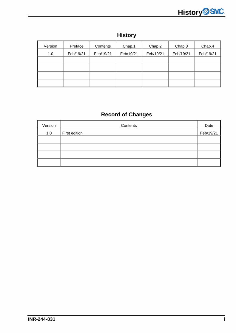
History
Version Preface Contents Chap.1 Chap.2 Chap.3 Chap.4
1.0 Feb/19/21 Feb/19/21 Feb/19/21 Feb/19/21 Feb/19/21 Feb/19/21
Record of Changes
Version Contents Date
1.0 First edition Feb/19/21
Preface
ii INR-244-831
Preface
Thank you very much for purchasing SMC Thermo-con.
This manual contains description for communication protocol of this product for your full benefit from this
product.
Read the operation manual carefully before use of this product, and understand the outline of the
product and safety instructions well. Instructions in the categories, “Danger”, “Warning” and “Caution”,
are important for safety and must be duly followed.
Please contact the following for any question and unclear points regarding the Thermo-con. SMC Corporation R&D Center Product Development Division-6 Address: 4-2-2, KINUNODAI,TSUKUBAMIRAI-CITY , IBARAKI-KEN 300-2493, JAPAN Phone:+81-297-52-6666 Fax:+81-297-20-5007 E-mail:[email protected]
Notice: The content of this manual can be revised without a previous notice.
Contents
INR-244-831 iii
Contents
1 PREPARATION FOR COMMUNICATION ---------------------------------------- 1-1
2 OPTIONS OF COMMUNICATION METHOD ------------------------------------- 2-1
2.1 COMMUNICATION PROCEDURE -------------------------------------------------------------------------- 2-1
3 COMMUNICATION FORMAT -------------------------------------------------------- 3-1
3.1 TYPE OF MESSAGE ---------------------------------------------------------------------------------------- 3-1
3.2 CONTENT OF COMMUNICATION -------------------------------------------------------------------------- 3-1
3.3 COMPOSITION OF REQUIRED MESSAGE (FROM MASTER TO THE PRODUCT) --------------------- 3-2
3.4 COMPOSITION OF RESPONSE MESSAGE (FROM THE PRODUCT TO MASTER) -------------------- 3-3
3.5 EXPLANATION OF CODE ----------------------------------------------------------------------------------- 3-4
3.6 CAUTIONS FOR COMMUNICATION ----------------------------------------------------------------------- 3-6
3.7 COMMUNICATION EXAMPLE ------------------------------------------------------------------------------ 3-7
3.8 CONNECTION ----------------------------------------------------------------------------------------------- 3-9
3.9 IDENTIFICATION CODE LIST ------------------------------------------------------------------------------ 3-9
3.10 ASCII CODE LIST --------------------------------------------------------------------------------------- 3-9
4 TROUBLESHOOTING ------------------------------------------------------------------ 4-1

Preparation for Communication
INR-244-831 1-1
1 Preparation for Communication
Make preparation for using communication facility as follows.
1) Turn off the power switch of Thermo-con. (Detach the communication connector when the power
switch of the thermo-con is turning off.)
2) Connect communication cable to communication connector of Thermo-con.
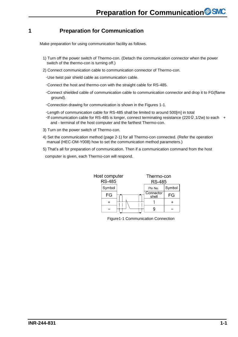
・Use twist pair shield cable as communication cable.
・Connect the host and thermo-con with the straight cable for RS-485.
・Connect shielded cable of communication cable to communication connector and drop it to FG(flame
ground).
・Connection drawing for communication is shown in the Figures 1-1.
・Length of communication cable for RS-485 shall be limited to around 500[m] in total
・If communication cable for RS-485 is longer, connect terminating resistance (220Ω,1/2w) to each +
and - terminal of the host computer and the farthest Thermo-con.
3) Turn on the power switch of Thermo-con.
4) Set the communication method (page 2-1) for all Thermo-con connected. (Refer the operation
manual (HEC-OM-Y008) how to set the communication method parameters.)
5) That’s all for preparation of communication. Then if a communication command from the host
computer is given, each Thermo-con will respond.
Figure1-1 Communication Connection

Specifications of Communication Method
INR-244-831 2-1
2 Options of Communication Method
Standards・・・・・・・・・・・・・・・・・・・・・・・・・・・・・・・・・・・・・
Circuit type・・・・・・・・・・・・・・・・・・・・・・・・・・・・・・・・・・・
Communication type・・・・・・・・・・・・・・・・・・・・・・・・・・・
Communication speed・・・・・・・・・・・・・・・・・・・・・・・・・・
Character code・・・・・・・・・・・・・・・・・・・・・・・・・・・・・・・・
Parity・・・・・・・・・・・・・・・・・・・・・・・・・・・・・・・・・・・・・・・・・
Start bit・・・・・・・・・・・・・・・・・・・・・・・・・・・・・・・・・・・・・・
Data length・・・・・・・・・・・・・・・・・・・・・・・・・・・・・・・・・・・
Stop bit・・・・・・・・・・・・・・・・・・・・・・・・・・・・・・・・・・・・・・・
BCC check・・・・・・・・・・・・・・・・・・・・・・・・・・・・・・・・・・・
Address・・・・・・・・・・・・・・・・・・・・・・・・・・・・・・・・・・・・・・・
RS-485
Half duplex
Asynchronous
2400,4800,9600,19200, 38400 bps
ASCII
None, even number, odd number
1 bit
7 bit or 8 bit.
1 bit or 2 bit.
Disable, Enable
1 to 99
Note: Values underlined indicate default values.
It is set to these values when delivered.
2.1 Communication Procedure
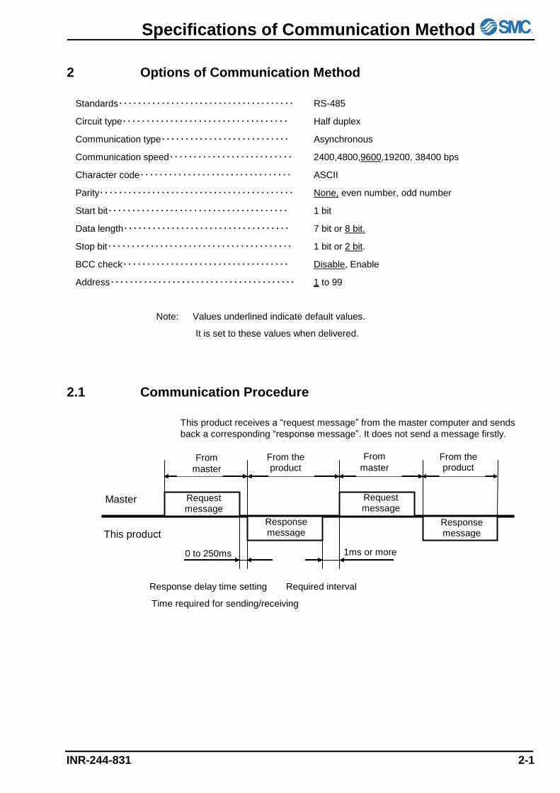
This product receives a “request message” from the master computer and sends
back a corresponding “response message”. It does not send a message firstly.
Response delay time setting Required interval
Time required for sending/receiving
Master
This product
From
master
0 to 250ms 1ms or more
Request message
Response message
From the product
From
master From the product
Response message
Request message

Communication Format
INR-244-831 3-1
3 Communication Format
3.1 Type of Message
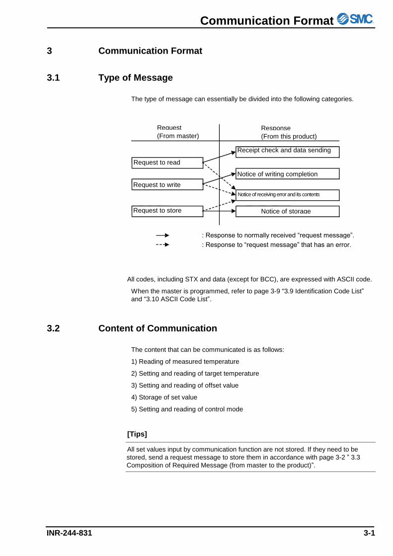
The type of message can essentially be divided into the following categories.
All codes, including STX and data (except for BCC), are expressed with ASCII code.
When the master is programmed, refer to page 3-9 "3.9 Identification Code List”
and “3.10 ASCII Code List”.
3.2 Content of Communication
The content that can be communicated is as follows:
1) Reading of measured temperature
2) Setting and reading of target temperature
3) Setting and reading of offset value
4) Storage of set value
5) Setting and reading of control mode
[Tips]
All set values input by communication function are not stored. If they need to be
stored, send a request message to store them in accordance with page 3-2 ” 3.3
Composition of Required Message (from master to the product)”.
Request
message Response message (From master) (From this product)
: Response to normally received “request message”.
Request to write
Request to store
Request to read
Receipt check and data sending
Notice of writing completion
Notice of receiving error and its contents
Notice of storage
completion
: Response to “request message” that has an error.
Communication Format
3-2 INR-244-831
3.3 Composition of Required Message (from master to the product)
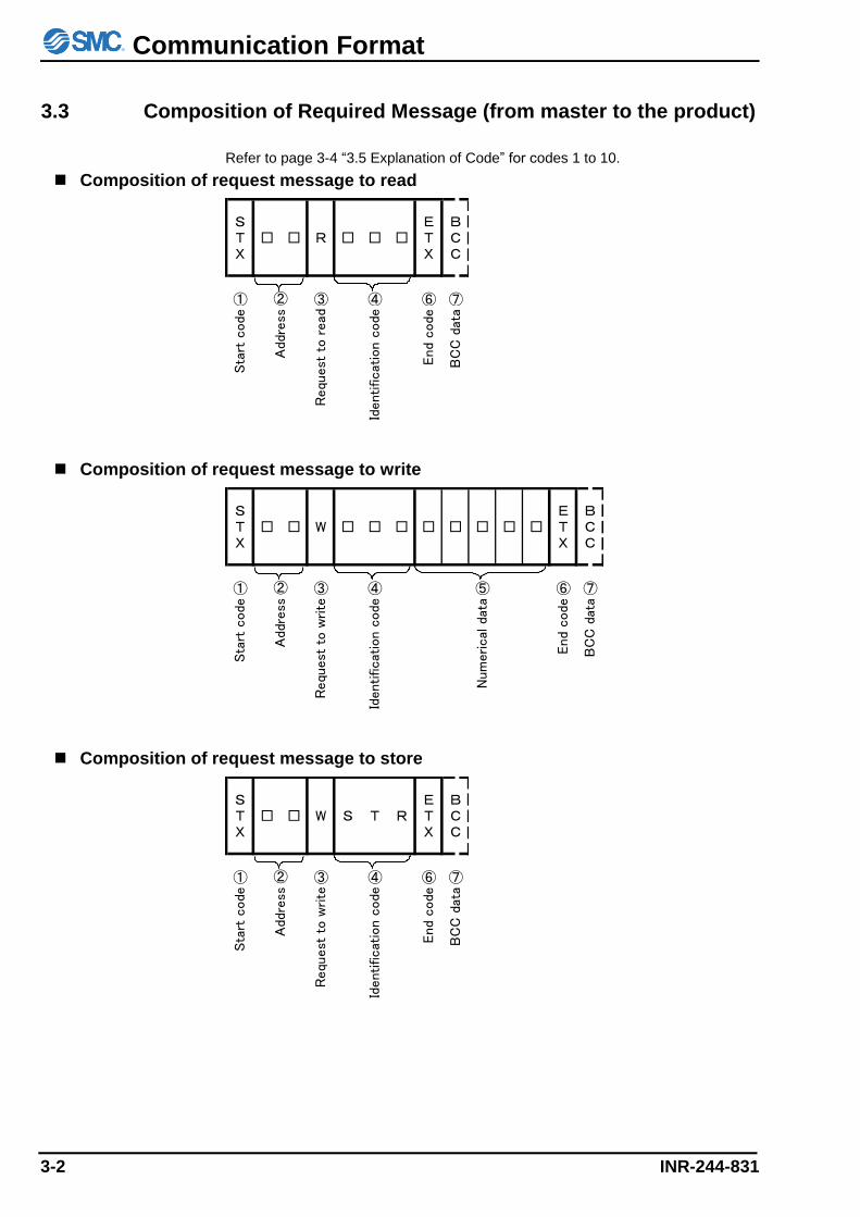
Refer to page 3-4 “3.5 Explanation of Code” for codes 1 to 10.
Composition of request message to read
STX
□ □ R □ □ □ETX
BCC
① ③ ④ ⑥ ⑦
Sta
rt c
ode
Requ
est
to r
ead
Identificat
ion c
ode
End
code
BC
C d
ata
②
Add
ress
Composition of request message to write
STX
□ □ W □ □ □ □ □ □ □ □ETX
BCC
① ③ ④ ⑤ ⑥ ⑦
Sta
rt c
ode
Requ
est
to w
rite
Identificat
ion c
ode
Num
erical
dat
a
End
code
BC
C d
ata
②
Add
ress
Composition of request message to store
STX
□ □ W S T RETX
BCC
① ③ ④ ⑥ ⑦
Sta
rt c
ode
Requ
est
to w
rite
Identificat
ion c
ode
End
code
BC
C d
ata
②
Add
ress
Communication Format
INR-244-831 3-3
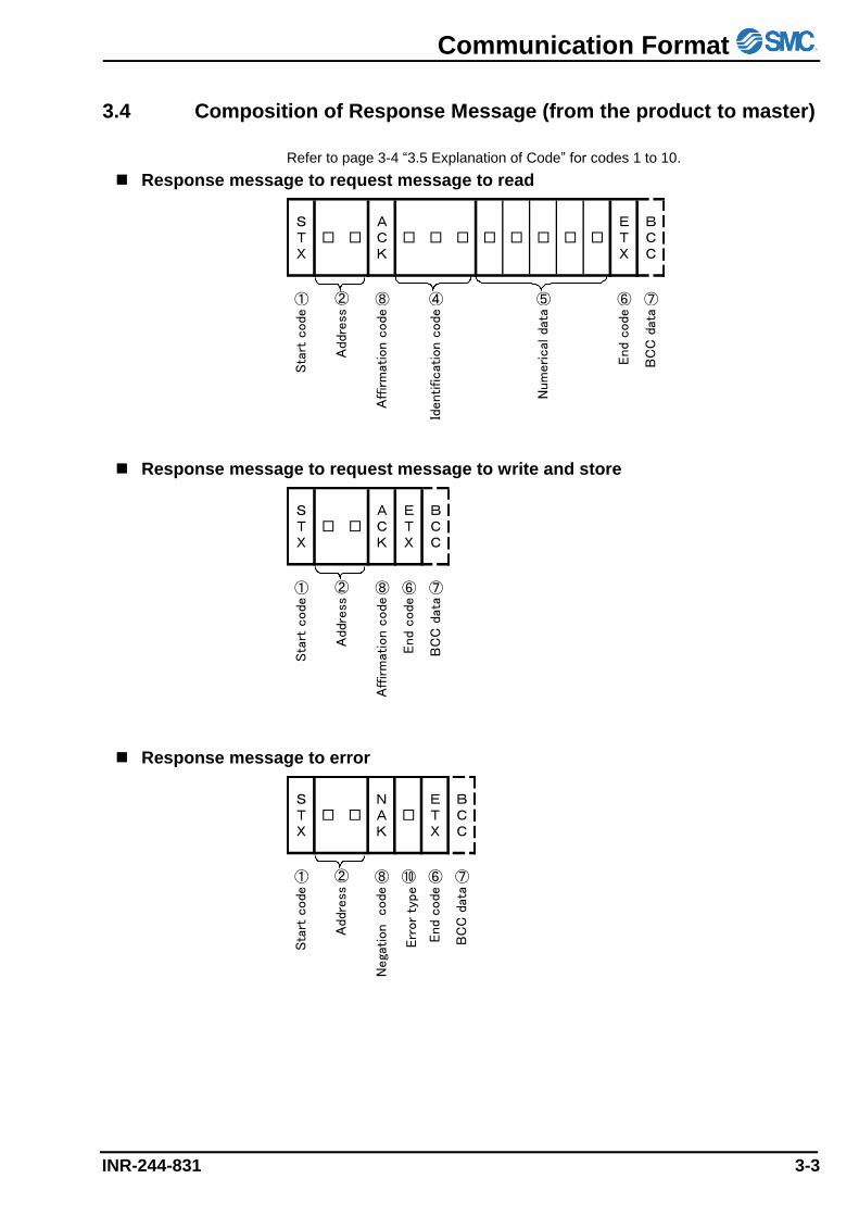
3.4 Composition of Response Message (from the product to master)
Refer to page 3-4 “3.5 Explanation of Code” for codes 1 to 10.
Response message to request message to read
STX
□ □ACK
□ □ □ □ □ □ □ □ETX
BCC
① ⑧ ④ ⑤ ⑥ ⑦Sta
rt c
ode
Affirm
atio
n c
ode
Identificat
ion c
ode
Num
erical
dat
a
End
code
BC
C d
ata
②
Add
ress
Response message to request message to write and store
STX
□ □ACK
ETX
BCC
① ⑧ ⑥ ⑦
Sta
rt c
ode
Aff
irm
atio
n c
ode
End c
ode
BC
C d
ata
②
Addre
ss
Response message to error
STX
□ □NAK
□ETX
BCC
① ⑧ ⑩ ⑥ ⑦
Sta
rt c
ode
Affirm
atio
n c
ode
Err
or
type
End
code
BC
C d
ata
②
Add
ress
Nega
tion
Communication Format
3-4 INR-244-831
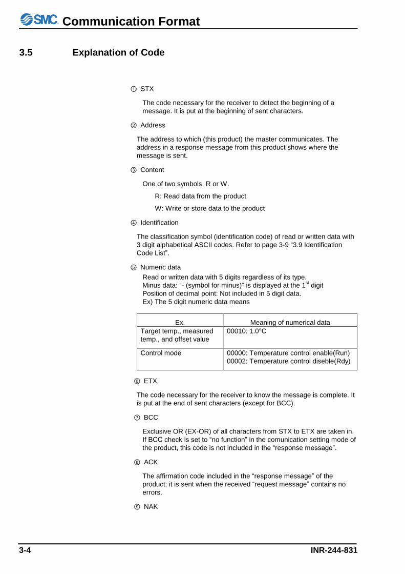
3.5 Explanation of Code
① STX
The code necessary for the receiver to detect the beginning of a
message. It is put at the beginning of sent characters.
② Address
The address to which (this product) the master communicates. The
address in a response message from this product shows where the
message is sent.
③ Content
One of two symbols, R or W.
R: Read data from the product
W: Write or store data to the product
④ Identification
The classification symbol (identification code) of read or written data with
3 digit alphabetical ASCII codes. Refer to page 3-9 “3.9 Identification
Code List”.
⑤ Numeric data
Read or written data with 5 digits regardless of its type.
Minus data: “- (symbol for minus)“ is displayed at the 1st digit
Position of decimal point: Not included in 5 digit data.
Ex) The 5 digit numeric data means
Ex. Meaning of numerical data
Target temp., measured
temp., and offset value
00010: 1.0°C
Control mode 00000: Temperature control enable(Run)
00002: Temperature control diseble(Rdy)
⑥ ETX
The code necessary for the receiver to know the message is complete. It
is put at the end of sent characters (except for BCC).
⑦ BCC
Exclusive OR (EX-OR) of all characters from STX to ETX are taken in.
If BCC check is set to “no function” in the comunication setting mode of
the product, this code is not included in the “response message”.
⑧ ACK
The affirmation code included in the “response message” of the
product; it is sent when the received “request message” contains no
errors.
⑨ NAK
Communication Format
INR-244-831 3-5
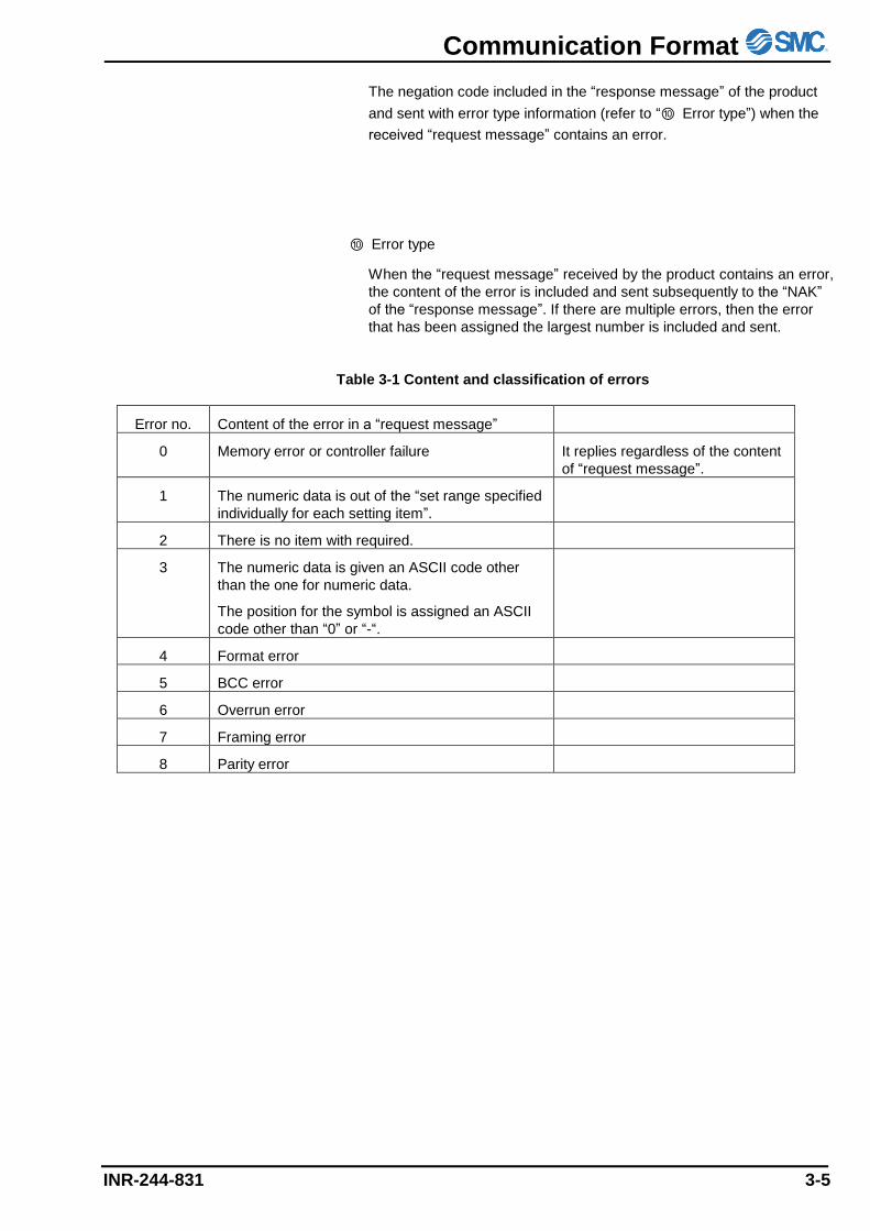
The negation code included in the “response message” of the product
and sent with error type information (refer to “⑩ Error type”) when the
received “request message” contains an error.
⑩ Error type
When the “request message” received by the product contains an error,
the content of the error is included and sent subsequently to the “NAK”
of the “response message”. If there are multiple errors, then the error
that has been assigned the largest number is included and sent.
Table 3-1 Content and classification of errors
Error no. Content of the error in a “request message”
0 Memory error or controller failure It replies regardless of the content
of “request message”.
1 The numeric data is out of the “set range specified
individually for each setting item”.
2 There is no item with required.
3 The numeric data is given an ASCII code other
than the one for numeric data.
The position for the symbol is assigned an ASCII
code other than “0” or “-“.
4 Format error
5 BCC error
6 Overrun error
7 Framing error
8 Parity error
Communication Format
3-6 INR-244-831
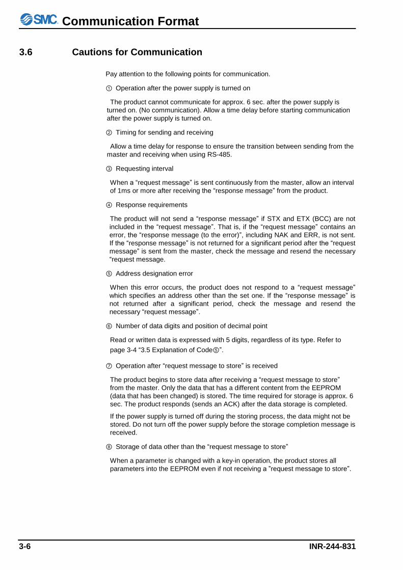
3.6 Cautions for Communication
Pay attention to the following points for communication.
① Operation after the power supply is turned on
The product cannot communicate for approx. 6 sec. after the power supply is
turned on. (No communication). Allow a time delay before starting communication
after the power supply is turned on.
② Timing for sending and receiving
Allow a time delay for response to ensure the transition between sending from the
master and receiving when using RS-485.
③ Requesting interval
When a “request message” is sent continuously from the master, allow an interval
of 1ms or more after receiving the “response message” from the product.
④ Response requirements
The product will not send a “response message” if STX and ETX (BCC) are not
included in the “request message”. That is, if the “request message” contains an
error, the “response message (to the error)”, including NAK and ERR, is not sent.
If the “response message” is not returned for a significant period after the “request
message” is sent from the master, check the message and resend the necessary
“request message.
⑤ Address designation error
When this error occurs, the product does not respond to a “request message”
which specifies an address other than the set one. If the “response message” is
not returned after a significant period, check the message and resend the
necessary “request message”.
⑥ Number of data digits and position of decimal point
Read or written data is expressed with 5 digits, regardless of its type. Refer to
page 3-4 “3.5 Explanation of Code⑤”.
⑦ Operation after “request message to store” is received
The product begins to store data after receiving a “request message to store”
from the master. Only the data that has a different content from the EEPROM
(data that has been changed) is stored. The time required for storage is approx. 6
sec. The product responds (sends an ACK) after the data storage is completed.
If the power supply is turned off during the storing process, the data might not be
stored. Do not turn off the power supply before the storage completion message is
received.
⑧ Storage of data other than the “request message to store”
When a parameter is changed with a key-in operation, the product stores all
parameters into the EEPROM even if not receiving a ”request message to store”.
Communication Format
INR-244-831 3-7
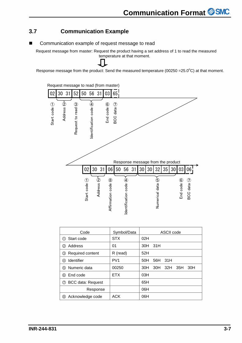
3.7 Communication Example
Communication example of request message to read
Request message from master: Request the product having a set address of 1 to read the measured
temperature at that moment.
Response message from the product: Send the measured temperature (00250 =25.0oC) at that moment.
Request message to read (from master)
Code Symbol/Data ASCII code
① Start code STX 02H
② Address 01 30H 31H
③ Required content R (read) 52H
④ Identifier PV1 50H 56H 31H
⑤ Numeric data 00250 30H 30H 32H 35H 30H
⑥ End code ETX 03H
⑦ BCC data: Request 65H
Response 06H
⑧ Acknowledge code ACK 06H
Response message from the product
02 30 31 52 50 56 31 03 65
① ③ ④ ⑥ ⑦
Sta
rt c
ode
Requ
est
to r
ead
Identificat
ion c
ode
End
code
BC
C d
ata
②
Add
ress
02 30 31 06 50 56 31 30 30 32 35 30 03 06
① ⑧ ④ ⑤ ⑥ ⑦
Sta
rt c
ode
Affirm
atio
n c
ode
Identificat
ion
code
Num
eric
al d
ata
End
code
BC
C d
ata
②
Add
ress
Communication Format
3-8 INR-244-831
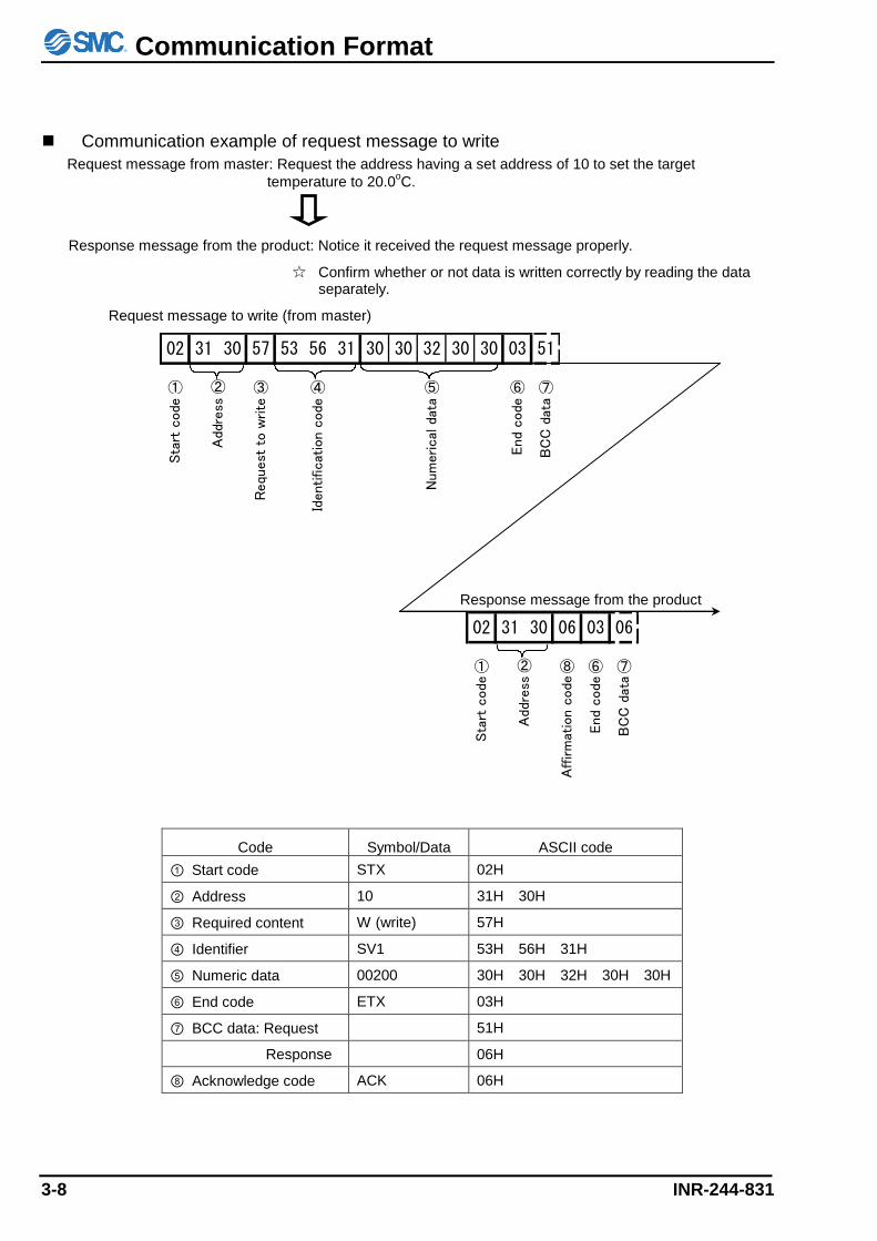
Communication example of request message to write
Request message from master: Request the address having a set address of 10 to set the target
temperature to 20.0oC.
Response message from the product: Notice it received the request message properly.
☆ Confirm whether or not data is written correctly by reading the data separately.
Request message to write (from master)
Code Symbol/Data ASCII code
① Start code STX 02H
② Address 10 31H 30H
③ Required content W (write) 57H
④ Identifier SV1 53H 56H 31H
⑤ Numeric data 00200 30H 30H 32H 30H 30H
⑥ End code ETX 03H
⑦ BCC data: Request 51H
Response 06H
⑧ Acknowledge code ACK 06H
Response message from the product
02 31 30 57 53 56 31 30 30 32 30 30 03 51
① ③ ④ ⑤ ⑥ ⑦
Sta
rt c
ode
Requ
est
to w
rite
Identificat
ion c
ode
Num
erical
dat
a
End
code
BC
C d
ata
②
Add
ress
02 31 30 06 03 06
① ⑧ ⑥ ⑦
Sta
rt c
ode
Aff
irm
atio
n c
ode
End c
ode
BC
C d
ata
②
Addre
ss
Communication Format
INR-244-831 3-9
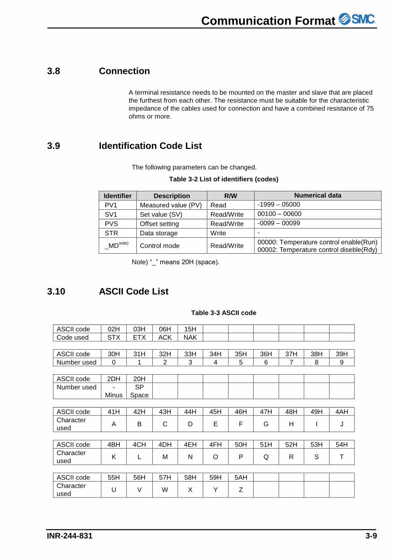
3.8 Connection
A terminal resistance needs to be mounted on the master and slave that are placed
the furthest from each other. The resistance must be suitable for the characteristic
impedance of the cables used for connection and have a combined resistance of 75
ohms or more.
3.9 Identification Code List
The following parameters can be changed.
Table 3-2 List of identifiers (codes)
Identifier Description R/W Numerical data
PV1 Measured value (PV) Read -1999 – 05000
SV1 Set value (SV) Read/Write 00100 – 00600
PVS Offset setting Read/Write -0099 – 00099
STR Data storage Write -
_MDnote)
Control mode Read/Write 00000: Temperature control enable(Run) 00002: Temperature control diseble(Rdy)
Note) “_” means 20H (space).
3.10 ASCII Code List
Table 3-3 ASCII code
ASCII code 02H 03H 06H 15H
Code used STX ETX ACK NAK
ASCII code 30H 31H 32H 33H 34H 35H 36H 37H 38H 39H
Number used 0 1 2 3 4 5 6 7 8 9
ASCII code 2DH 20H
Number used -
Minus
SP
Space
ASCII code 41H 42H 43H 44H 45H 46H 47H 48H 49H 4AH
Character
used A B C D E F G H I J
ASCII code 4BH 4CH 4DH 4EH 4FH 50H 51H 52H 53H 54H
Character
used K L M N O P Q R S T
ASCII code 55H 56H 57H 58H 59H 5AH
Character
used U V W X Y Z

Troubleshooting
INR-244-831 4-1
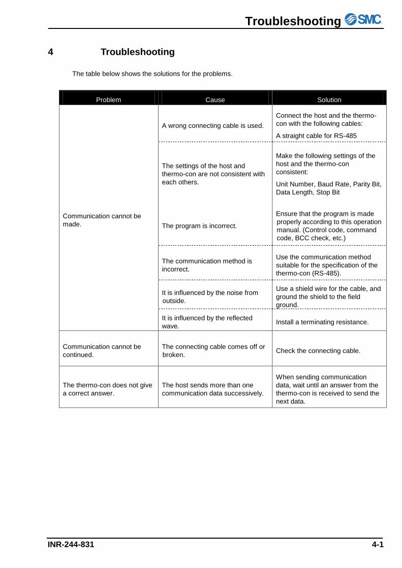
4 Troubleshooting
The table below shows the solutions for the problems.
Problem Cause Solution
Communication cannot be
made.
A wrong connecting cable is used.
Connect the host and the thermo-
con with the following cables:
A straight cable for RS-485
The settings of the host and
thermo-con are not consistent with
each others.
Make the following settings of the
host and the thermo-con
consistent:
Unit Number, Baud Rate, Parity Bit,
Data Length, Stop Bit
The program is incorrect.
Ensure that the program is made
properly according to this operation
manual. (Control code, command
code, BCC check, etc.)
The communication method is
incorrect.
Use the communication method
suitable for the specification of the
thermo-con (RS-485).
It is influenced by the noise from
outside.
Use a shield wire for the cable, and
ground the shield to the field
ground.
It is influenced by the reflected
wave. Install a terminating resistance.
Communication cannot be
continued.
The connecting cable comes off or
broken. Check the connecting cable.
The thermo-con does not give
a correct answer.
The host sends more than one
communication data successively.
When sending communication
data, wait until an answer from the
thermo-con is received to send the
next data.

4-14-1, Sotokanda, Chiyoda-ku, Tokyo 101-0021 JAPAN
Tel: + 81 3 5207 8249 Fax: +81 3 5298 5362
URL https://www.smcworld.com Note: Specifications are subject to change without prior notice and any obligation on the part of the manufacturer. © 2021 SMC Corporation All Rights Reserved
Revision history


![Serial Communication [Modbus Version] - Intelligent Actuator · Serial Communication [Modbus Version] Operation Manual, Tenth Edition . Modbus . Modbus Please Read Before Use Thank](https://img.pdfslide.net/doc/110x75/5eb89d6eaa14655c6b0fb9ce/serial-communication-modbus-version-intelligent-actuator-serial-communication.jpg)


![Serial Communication [Modbus Version] Operation Manual ......RCP6 (PLC Unit) ERC2, ERC3 Serial Communication [Modbus Version] Operation Manual, Ninth Edition . Modbus . Modbus Please](https://img.pdfslide.net/doc/110x75/5e6d973e9fc0481438519dec/serial-communication-modbus-version-operation-manual-rcp6-plc-unit-erc2.jpg)