Embed Size (px)
Citation preview

SER
IAL
INTE
RFA
CE
Serie
s SS
W-0
5
MANUAL OF THE
SERIAL
COMMUNICATION
SSW-05
CODE 0899.4895 E/4

MANUAL OF THE SERIAL
COMUNICATION SSW-05
Series: SSW-05 Software: Version 2.1X 0899.4895 E/4
WEG AUTOMAÇÃO Av. Pref. Valdemar Grubba, 3000
89256-900 Jaraguá do Sul, SC – Brasil Tel.(047)372-4000 – Fax(047)372-4020
email: [email protected]
ATTENTION! It is very important to check if the software version is the same as indicated above.


_______ Summary _______
SAFETY NOTICES 1
1.1 Safety Notices in the Manual....................................... 1.2 Safety Notices on the Product .................................... 1.3 Preliminary Recommendations....................................
1 1 2
INTRODUCTION 2
2.1 About this Manual........................................................ 2.2 About WEG Protocol....................................................
3 3
COMMUNICATION INTERFACES 3
3.1 RS-485 Interface.......................................................... 3.2 RS-232 Interface.........................................................
3.2.1 RS-232 Electrical Characteristics........................ 3.2.2 Cares with RS-232.............................................. 3.2.3 RS-232 Connections........................................... 3.2.4 Description of the Soft-Starter Serial Connector. 3.2.5 Definition of the RS-232 Cable............................ 3.2.6 Description of the Master Connector (RJ)........... 3.2.7 Definition of the RS-232 PC Cable...................... 3.2.8 Description of the PC (DB9) Connector...............
5 7 7 7 8 8 8 8 9 9
DEFINITIONS 4
4.1 Used Terms................................................................. 4.2 Block Diagram.............................................................. 4.3 Variable Standardization.............................................. 4.4 Character Format......................................................... 4.5 Protocol........................................................................
4.5.1 Reading Telegram............................................... 4.5.2 Writing Telegram.................................................
4.6 Execution and Test Telegram...................................... 4.7 Telegram Sequence .................................................... 4.8 Variable Code.............................................................. 4.9 Times...........................................................................
10 10 11 13 13 14 15 16 16 17 17
TELEGRAM EXAMPLES 5
5.1 Example 1.................................................................... 5.2 Example 2....................................................................
18 18
VARIABLES OF THE SERIAL COMMUNICATION 6
6.1.1 V00 Indication of the Equipment Model................... 6.1.2 V01 Indication of the Soft-Starter Status................... 6.1.3 V02 Indication of the Soft-Starter Errors................... 6.1.4 V03 Logic Command Selection.................................
19 19 20 22
ERRORS AND SERI AL COMMUNICATION PARAMETERS 7
7.1 Parameters related to the Serial Communication ....... 7.2 Errors Related to the Serial Communication ...............
23 23
DETAILED PARAMETER DESCRIPTION 8
8.1 P000 – Access Parameter........................................... 8.2 P002 – Motor Current Indication (%)........................... 8.3 P003 – Motor Current Indication (A)........................... 8.4 P023 – Software Version............................................. 8.5 P030 – R Phase Current.............................................. 8.6 P030 – S Phase Current.............................................. 8.7 P030 – T Phase Current.............................................. 8.8 P050 – Status Indication of the Motor Thermal Protection ....................................................... 8.9 P101 – Initial Voltage (% Un)....................................... 8.10 P102 – Time of Acceleration Ramp (s)...................... 8.11 P104 – Time of Deceleration Ramp (s)...................... 8.12 P105 – Motor Current Setting (%)............................. 8.13 P106 – Protection Configuration............................... 8.14 P204 – Load Factory Setting..................................... 8.15 P206 – Auto-Reset Time............................................ 8.16 P215 – Keypad Copy Function.................................. 8.17 P220 – HMI / (Trimpots and Dip Switch) Selection.... 8.18 P264 – Programmable Digital Input DI 1................... 8.19 P277 – Programmable Relay Output (14/23 – 24).... 8.20 P295 – Rated Current of the Soft-Starter.................. 8.21 P308 – Network Address........................................... 8.22 P313 – Action of the Serial Communication Verification......................................................................... 8.23 P314 – Verification Time of the Serial Communication..................................................................
24 24 24 24 24 24 24
24 25 25 26 26 27 30 30 30 32 32 33 33 33
34
34
TROUBLESHOOTING 9
Problem and Corrective Action.......................................... 35
SAFETY NOTICES 1
1
This Manual cont ains all necessary information for the correct use of the Serial Communication of the SSW -05 Soft-Starter.
This Manual has been written for qualified personnel with suitable training or technical qualification to operate serial interfaces and their respective communication protoco ls.
1.1 SAFETY NOTICES
IN THE MANUAL
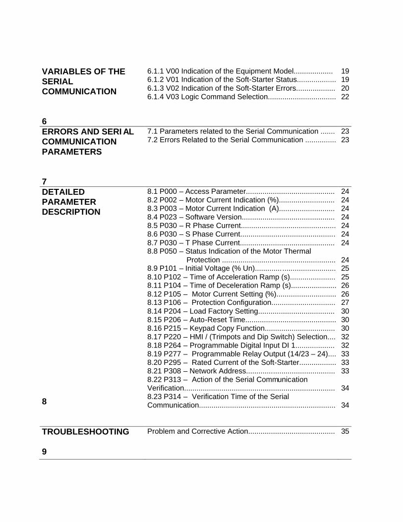
The following Safety Notices will be used in this Manual: DANGER! If the Safety Instructions are not strictly observed, it can lead to serious of fatal injuries of personnel and/or equipment damage. ATTENTION! Failure to observe the recommended Safety Procedures can lead to material damage. NOTE! The text aims at to provide important information for the correct understanding and proper product performance.
1.2 SAFETY NOTICES ON THE PRODUCT
The following symbols may be attached to the product, serving as Safety Notice: High Voltages. Components sensitive to electrostatic discharge. Do not touch them Mandatory connection to ground protection (PE). Shield connection to ground.
1 SAFETY NOTICES
2
1.3 PRELIMINARY RECOMMENDATIONS
DANGER! Only qualified personnel should plan or implement the installation, startup, operation and maintenance of serial interfaces. Read this manual before attempt any installation and operation of the Soft-Starter by following carefully all safety notices here indicated. Please follow the safety instructions indicated in this Manual, in the Soft-Starter Manual and/or defined by local regulations. If personnel injuries or equipment damages can occurs due to motors driven by motor starters, please provide always the required electromechanical safety devices. If remote control (via serial interface) is used, please take all required precautions to avoid personnel injuries and machine and installations damages. Failure to comply with these instruction may result in personnel injury and/or equipment damage. DANGER! Always disconnect the equipment from the power supply before open it. ATTENTION! The electronic boards are fitted with components sensitive to electrostatic discharges. Never touch any electrical component or connector directly. If necessary to do so, touch before the properly grounded metallic frame or use a suitable ground strap.
NOTE! In general, communication networks are sensitive to interference generated by other equipment. In this case, please follow all recommended instructions.
INTRODUCTION 2
3
2.1 ABOUT THIS MANUAL
This Manual describes how to install, start-up, operate and identify problems related do the serial interface of WEG Soft-Starters. For more information, training or services, please contact:
WEG Service:
WEG AUTOMAÇÃO Tel. (0800) 475767
Fax: (047) 372-4020 NOTE! If you need information or services, please make available following data: þ model of WEG product; þ serial number and manufacturing date as indicated on
WEG product nameplate; þ version of installed software.
2.2 ABOUT WEG PROTOCOL
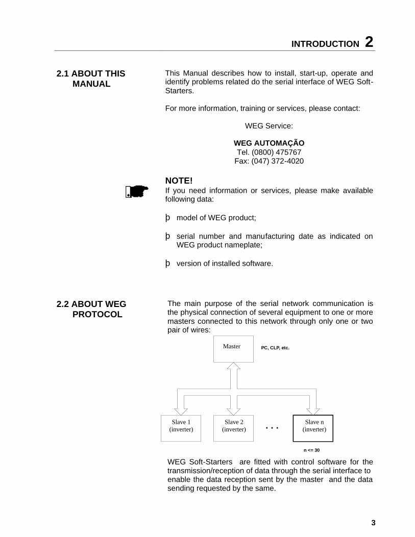
The main purpose of the serial network communication is the physical connection of several equipment to one or more masters connected to this network through only one or two pair of wires: WEG Soft-Starters are fitted with control software for the transmission/reception of data through the serial interface to enable the data reception sent by the master and the data sending requested by the same.
MESTRE
ESCRAVO 2
(conversor)
ESCRAVO 1
(conversor)
ESCRAVO n
(conversor)
n <= 30
. . .
PC, CLP, etc.Master
Slave 2 (inverter)
Slave n (inverter)
Slave 1 (inverter)

2 INTRODUCTION
4
The transfer rate is 9.600Bps, following an exchange protocol, type question/answer, meeting ISO 1745 standard for the data transmission in code. The master is able to realize the following operations related to each WEG equipment connected to the network: þ Identification:
• Network number; • Soft-Starter type (model); • Software version. þ Commands:
• general enabling/disabling; • error reset. þ Status Recognition:
• enabling/disabling; • in acceleration; • at rated voltage; • in deceleration; • in error. þ Parameter Reading or Changing. Typical examples of WEG network use:
• Supervisory monitoring at the same time several variables of WEG Soft-Starters;
• PLC controlling the operation of several WEG Soft-
Starters WEG in an industrial process.
NOTE!
WEG protocol is the same for all WEG equipment, but the logic command words, the basic variables and the parameters can differ among equipment.
COMMUNICATION INTERF ACES 3
5
The physical connection between WEG Soft-Starters is performed according to one of the standards below: þ RS-232 point to point, up to 10m (32.8 ft); þ RS-485 multipoint, with the use of the MIW-02 serial
interface module, with galvanic insulation, up to 1000m (3280 ft).
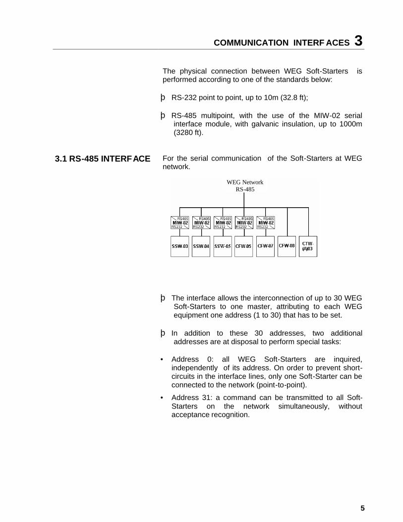
3.1 RS-485 INTERFACE For the serial communication of the Soft-Starters at WEG network.
þ The interface allows the interconnection of up to 30 WEG Soft-Starters to one master, attributing to each WEG equipment one address (1 to 30) that has to be set.
þ In addition to these 30 addresses, two additional
addresses are at disposal to perform special tasks: • Address 0: all WEG Soft-Starters are inquired,
independently of its address. On order to prevent short-circuits in the interface lines, only one Soft-Starter can be connected to the network (point-to-point).
• Address 31: a command can be transmitted to all Soft-Starters on the network simultaneously, without acceptance recognition.
WEG Network RS-485
3 COMMUNICATION INTERFACES
6
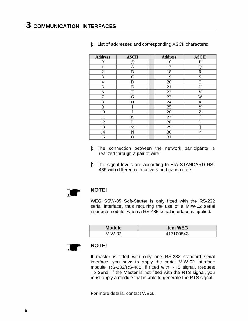
þ List of addresses and corresponding ASCII characters:
Address ASCII Address ASCII 0 @ 16 P 1 A 17 Q 2 B 18 R 3 C 19 S 4 D 20 T 5 E 21 U 6 F 22 V 7 G 23 W 8 H 24 X 9 I 25 Y
10 J 26 Z 11 K 27 [ 12 L 28 \ 13 M 29 ] 14 N 30 ^
15 O 31 _ þ The connection between the network participants is
realized through a pair of wire. þ The signal levels are according to EIA STANDARD RS-
485 with differential receivers and transmitters.
NOTE! WEG SSW-05 Soft-Starter is only fitted with the RS-232 serial interface, thus requiring the use of a MIW-02 serial interface module, when a RS-485 serial interface is applied.
Module Item WEG MIW-02 417100543 NOTE!
If master is fitted with only one RS-232 standard serial interface, you have to apply the serial MIW-02 interface module, RS-232/RS-485, if fitted with RTS signal, Request To Send. If the Master is not fitted with the RTS signal, you must apply a module that is able to generate the RTS signal. For more details, contact WEG.
COMMUNICATION INTERF ACES 3
7
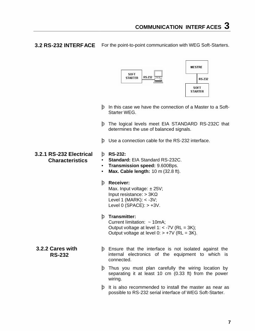
3.2 RS-232 INTERFACE For the point-to-point communication with WEG Soft-Starters.
þ In this case we have the connection of a Master to a Soft-Starter WEG.
þ The logical levels meet EIA STANDARD RS-232C that
determines the use of balanced signals. þ Use a connection cable for the RS-232 interface.
3.2.1 RS-232 Electrical Characteristics
þ RS-232: • Standard: EIA Standard RS-232C. • Transmission speed: 9.600Bps. • Max. Cable length: 10 m (32.8 ft). þ Receiver:
Max. Input voltage: ± 25V; Input resistance: > 3KΩ Level 1 (MARK): < -3V; Level 0 (SPACE): > +3V.
þ Transmitter:
Current limitation: ~ 10mA; Output voltage at level 1: < -7V (RL = 3K); Output voltage at level 0: > +7V (RL = 3K).
3.2.2 Cares with RS-232
þ Ensure that the interface is not isolated against the internal electronics of the equipment to which is connected.
þ Thus you must plan carefully the wiring location by separating it at least 10 cm (0.33 ft) from the power wiring.
þ It is also recommended to install the master as near as possible to RS-232 serial interface of WEG Soft-Starter.
3 COMMUNICATION INTERFACES
8
3.2.3 RS-232 CONNECTION
þ The RS-232 must be connected directly point-to-point. þ There are two standard WEG cables, as described below.
3.2.4 Description of the Soft-Starter Serial Connector
þ SSW-05 connector (Serial Port).
TERMINAL SYMBOL DESCRIPTION 1 +5V +5V ±5% 2 RTS Request To Send 3 GND 0V 4 Rx Data reception 5 GND 0V 6 Tx Data transmission
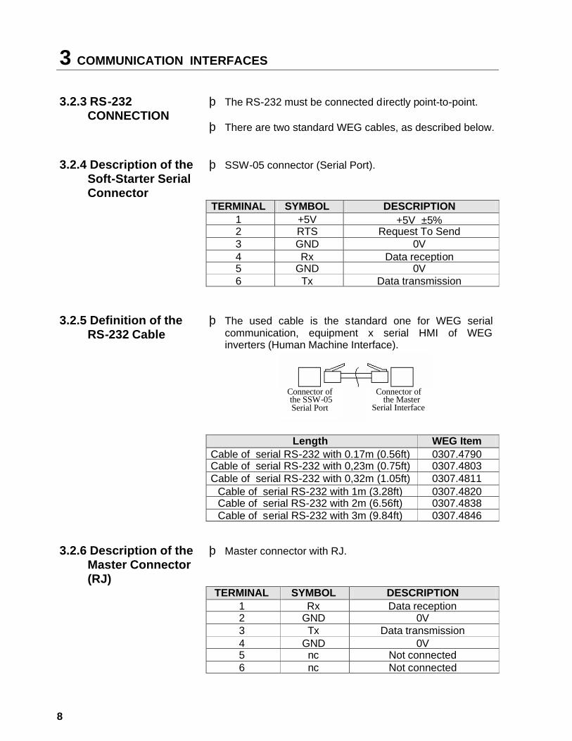
3.2.5 Definition of the RS-232 Cable
þ The used cable is the standard one for WEG serial communication, equipment x serial HMI of WEG inverters (Human Machine Interface).
Length WEG Item Cable of serial RS-232 with 0.17m (0.56ft) 0307.4790 Cable of serial RS-232 with 0,23m (0.75ft) 0307.4803 Cable of serial RS-232 with 0,32m (1.05ft) 0307.4811
Cable of serial RS-232 with 1m (3.28ft) 0307.4820 Cable of serial RS-232 with 2m (6.56ft) 0307.4838 Cable of serial RS-232 with 3m (9.84ft) 0307.4846
3.2.6 Description of the Master Connector (RJ)
þ Master connector with RJ.
TERMINAL SYMBOL DESCRIPTION 1 Rx Data reception 2 GND 0V 3 Tx Data transmission 4 GND 0V 5 nc Not connected
6 nc Not connected
Connector of the SSW-05 Serial Port
Connector of the Master
Serial Interface
COMMUNICATION INTERF ACES 3
9
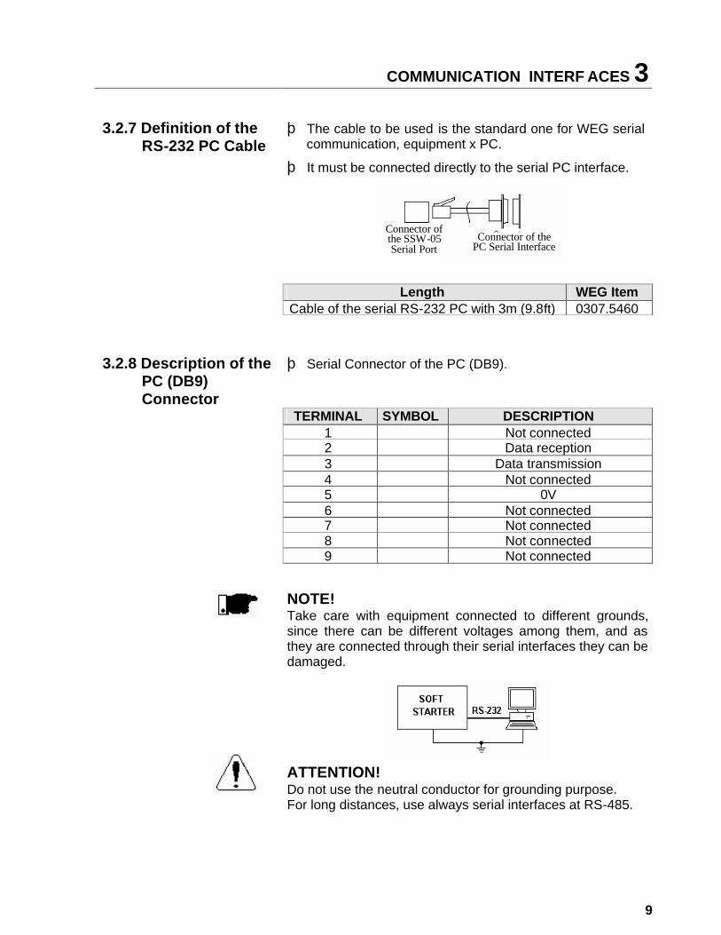
3.2.7 Definition of the RS-232 PC Cable
þ The cable to be used is the standard one for WEG serial communication, equipment x PC.
þ It must be connected directly to the serial PC interface.
Length WEG Item Cable of the serial RS-232 PC with 3m (9.8ft) 0307.5460
3.2.8 Description of the PC (DB9) Connector
þ Serial Connector of the PC (DB9).
TERMINAL SYMBOL DESCRIPTION 1 Not connected 2 Data reception 3 Data transmission 4 Not connected 5 0V 6 Not connected 7 Not connected 8 Not connected 9 Not connected
NOTE!
Take care with equipment connected to different grounds, since there can be different voltages among them, and as they are connected through their serial interfaces they can be damaged. ATTENTION! Do not use the neutral conductor for grounding purpose. For long distances, use always serial interfaces at RS-485.
Connector of the SSW-05 Serial Port
Connector of the PC Serial Interface
4 DEFINITIONS
10
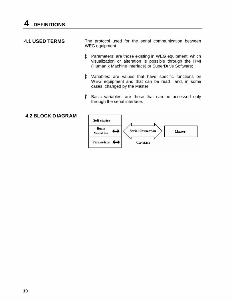
4.1 USED TERMS The protocol used for the serial communication between WEG equipment. þ Parameters: are those existing in WEG equipment, which
visualization or alteration is possible through the HMI (Human x Machine Interface) or SuperDrive Software;
þ Variables: are values that have specific functions on
WEG equipment and that can be read and, in some cases, changed by the Master;
þ Basic variables: are those that can be accessed only
through the serial interface.
4.2 BLOCK DIAGRAM

DEFINITIONS 4
11
4.3 VARIABLE STANDARDIZATION
The variable exchange is subject to the following standardization.
Value and Function Table of the Parameter of V2.1X software version to implement: changing, and commands via serial communication.
Parameter Parameter Function (Reading)
Range of the internal values
Factory Setting
User Setting Page
0 ... 4, 6... 9999 = Read P000 (2) Parameter Access
5 = Alteration 0 24
P002 Motor Current Indication (%) 000,0 ... 999,9 (% In) 24
P003 Motor Current Indication (A) 000,0 ... 999,9 (A) 24
P023 Software Version 24
P030 R Phase Current 000.0 ... 999,9 (A) 24
P031 S Phase Current 000.0 ... 999,9 (A) 24
P032 T Phase Current 000.0 ... 999,9 (A) 24
P050 Status Indication of the motor overload protection
0 ... 250 250 = error 24
Parameter Parameter Function (Reading and Writing)
Range of the internal values
Factory Setting
User Setting Page
P101 Initial voltage 30 ... 80 (% Un) 30 25 P102 Time of the Acceleration Ramp 1 ... 20 (s) 10 25 P104 Time of the Deceleration Ramp 0 ... 20 (s) 0 = off 26
P105 (1) Motor Current Setting 30 ... 100 (%) 100 26
P106 (1) Protection Configuration 0 ... 3F Hexadecimal
1F Hex.
27
0 = No function 1 = No function 2 = No function 3 = No function 4 = No function
P204 (1) Load Factory Setting
5 = Load factory default
0
30
P206 Auto-Reset Time 1 ... 1200 s 900 30
4 DEFINITIONS
12
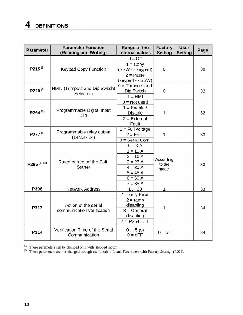
Parameter Parameter Function (Reading and Writing)
Range of the internal values
Factory Setting
User Setting Page
0 = Off 1 = Copy
(SSW -> keypad) P215 (1) Keypad Copy Function 2 = Paste
(keypad -> SSW)
0 30
0 = Trimpots and Dip Switch P220 (1) HMI / (Trimpots and Dip Switch)
Selection 1 = HMI 0 32
0 = Not used 1 = Enable /
Disable P264 (1) Programmable Digital Input DI 1
2 = External Fault
1 32
1 = Full voltage 2 = Error P277 (1) Programmable relay output
(14/23 - 24) 3 = Serial Com. 1 33
0 = 3 A 1 = 10 A 2 = 16 A 3 = 23 A 4 = 30 A 5 = 45 A 6 = 60 A
P295 (1) (2) Rated current of the Soft-Starter
7 = 85 A
According to the model
33
P308 Network Address 1 ... 30 1 33 1 = only Error
2 = ramp disabling
3 = General disabling
P313 Action of the serial communication verification
4 = P264 → 1
1
34
P314 Verification Time of the Serial Communication
0 ... 5 (s) 0 = oFF 0 = off
34
(1) These parameters can be changed only with stopped motor. (2) These parameters are not changed through the function “Loads Parameters with Factory Setting” (P204).
DEFINITIONS 4
13
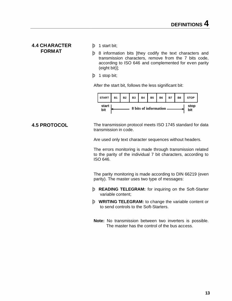
4.4 CHARACTER
FORMAT þ 1 start bit;
þ 8 information bits [they codify the text characters and transmission characters, remove from the 7 bits code, according to ISO 646 and complemented for even parity (eight bit)];
þ 1 stop bit;
After the start bit, follows the less significant bit:
4.5 PROTOCOL The transmission protocol meets ISO 1745 standard for data transmission in code. Are used only text character sequences without headers. The errors monitoring is made through transmission related to the parity of the individual 7 bit characters, according to ISO 646. The parity monitoring is made according to DIN 66219 (even parity). The master uses two type of messages: þ READING TELEGRAM: for inquiring on the Soft-Starter
variable content;
þ WRITING TELEGRAM: to change the variable content or to send controls to the Soft-Starters.
Note: No transmission between two inverters is possible.
The master has the control of the bus access.
B2 B3 B4 B5 B6 B7 B8B1START
startbit
stopbit
STOP
8 bits of information
4 DEFINITIONS
14
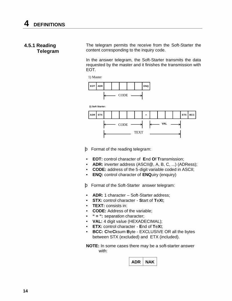
4.5.1 Reading
Telegram The telegram permits the receive from the Soft-Starter the content corresponding to the inquiry code. In the answer telegram, the Soft-Starter transmits the data requested by the master and it finishes the transmission with EOT.
þ Format of the reading telegram: • EOT: control character of End Of Transmission; • ADR: inverter address (ASCII@, A, B, C, ...) (ADRess); • CODE: address of the 5-digit variable coded in ASCII; • ENQ: control character of ENQuiry (enquiry) þ Format of the Soft-Starter answer telegram: • ADR: 1 character – Soft-Starter address; • STX: control character - Start of TeXt; • TEXT: consists in: • CODE: Address of the variable; • “ = “: separation character; • VAL: 4 digit value (HEXADECIMAL); • ETX: control character - End of TeXt; • BCC: CheCksum Byte - EXCLUSIVE OR all the bytes
between STX (excluded) and ETX (included). NOTE: In some cases there may be a soft-starter answer
with:
ADR
NAK
EOT ADR ENQ
1) Mestre:
2) Soft Starter:
ADR STX = ETX BCC
TEXTO
CÓDIGO VAL
CÓDIGO
1) Master
CODE
CODE
TEXT
DEFINITIONS 4
15
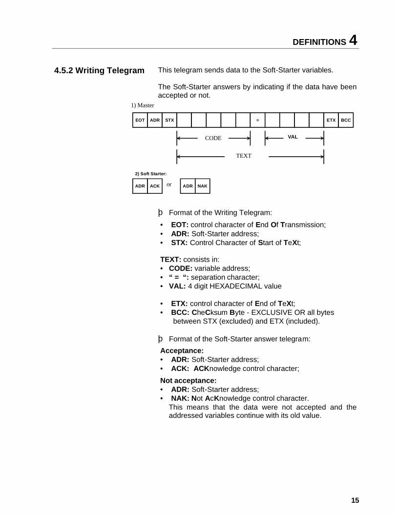
4.5.2 Writing Telegram This telegram sends data to the Soft-Starter variables.
The Soft-Starter answers by indicating if the data have been accepted or not.
þ Format of the Writing Telegram: • EOT: control character of End Of Transmission; • ADR: Soft-Starter address; • STX: Control Character of Start of TeXt; TEXT: consists in: • CODE: variable address; • “ = “: separation character; • VAL: 4 digit HEXADECIMAL value • ETX: control character of End of TeXt; • BCC: CheCksum Byte - EXCLUSIVE OR all bytes
between STX (excluded) and ETX (included). þ Format of the Soft-Starter answer telegram: Acceptance: • ADR: Soft-Starter address; • ACK: ACKnowledge control character; Not acceptance: • ADR: Soft-Starter address; • NAK: Not AcKnowledge control character.
This means that the data were not accepted and the addressed variables continue with its old value.
EOT ADR STX = ETX BCC
1) Mestre:
2) Soft Starter:
ADR ACK ADR NAKOU
CÓDIGO VAL
TEXTO
1) Mestre:1) Master
CODE
TEXT
or
4 DEFINITIONS
16
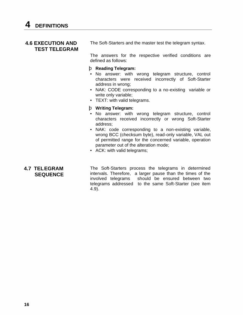
4.6 EXECUTION AND TEST TELEGRAM
The Soft-Starters and the master test the telegram syntax. The answers for the respective verified conditions are defined as follows:
þ Reading Telegram: • No answer: with wrong telegram structure, control
characters were received incorrectly of Soft-Starter address in wrong;
• NAK: CODE corresponding to a no-existing variable or write only variable;
• TEXT: with valid telegrams.
þ Writing Telegram: • No answer: with wrong telegram structure, control
characters received incorrectly or wrong Soft-Starter address;
• NAK: code corresponding to a non-existing variable, wrong BCC (checksum byte), read-only variable, VAL out of permitted range for the concerned variable, operation parameter out of the alteration mode;
• ACK: with valid telegrams;
4.7 TELEGRAM
SEQUENCE The Soft-Starters process the telegrams in determined intervals. Therefore, a larger pause than the times of the involved telegrams should be ensured between two telegrams addressed to the same Soft-Starter (see item 4.9).
DEFINITIONS 4
17
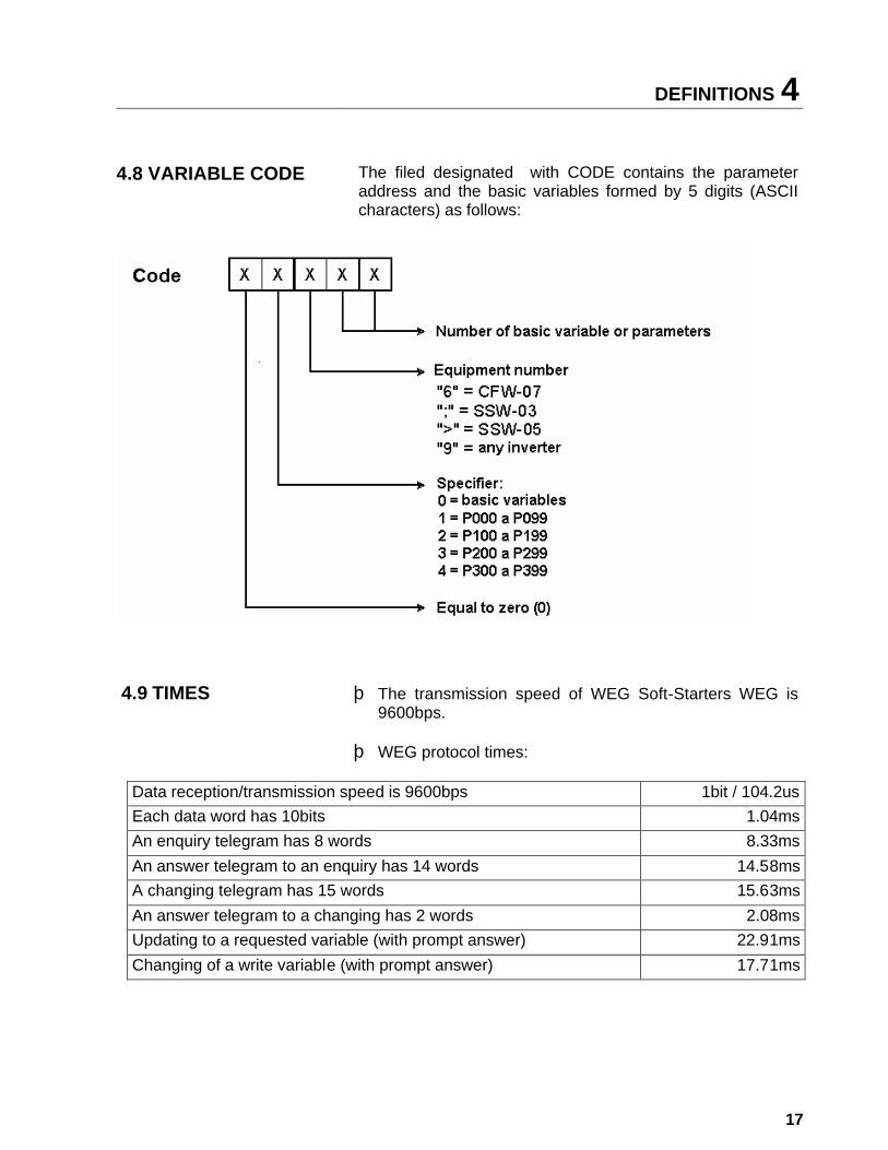
4.8 VARIABLE CODE The filed designated with CODE contains the parameter
address and the basic variables formed by 5 digits (ASCII characters) as follows:
þ The transmission speed of WEG Soft-Starters WEG is 9600bps.
4.9 TIMES
þ WEG protocol times:
Data reception/transmission speed is 9600bps 1bit / 104.2us Each data word has 10bits 1.04ms An enquiry telegram has 8 words 8.33ms An answer telegram to an enquiry has 14 words 14.58ms A changing telegram has 15 words 15.63ms An answer telegram to a changing has 2 words 2.08ms Updating to a requested variable (with prompt answer) 22.91ms
Changing of a write variable (with prompt answer) 17.71ms
Equal to zero (0)
5 TELEGRAM EXAMPLES
18
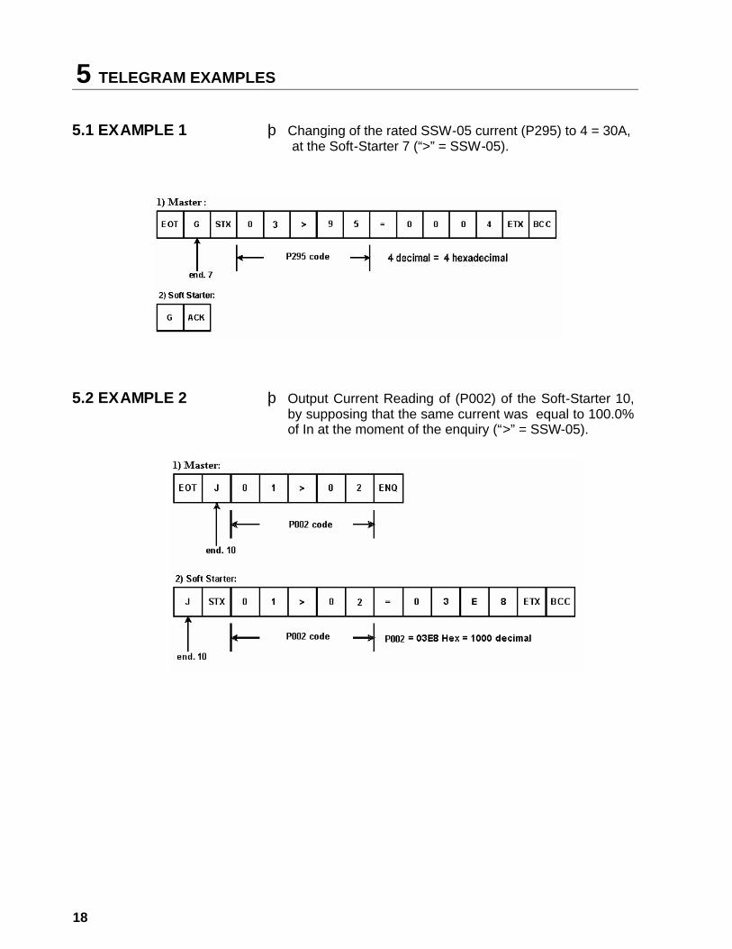
5.1 EXAMPLE 1 þ Changing of the rated SSW-05 current (P295) to 4 = 30A, at the Soft-Starter 7 (“>” = SSW-05).
5.2 EXAMPLE 2 þ Output Current Reading of (P002) of the Soft-Starter 10, by supposing that the same current was equal to 100.0% of In at the moment of the enquiry (“>” = SSW-05).
VARIABLES OF THE SERIAL COMMUNICATION 6
19
6.1 BASIC VARIABLES
6.1.1 V00 (code 00>00) þ Indication of the equipment model. þ Read Variable;
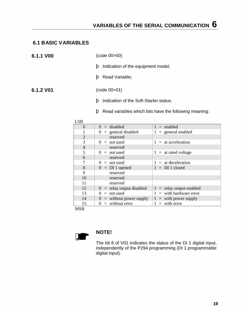
6.1.2 V01 (code 00>01) þ Indication of the Soft-Starter status. þ Read variables which bits have the following meaning:
LSB 0 0 = disabled 1 = enabled 1 0 = general disabled 1 = general enabled 2 reserved 3 0 = not used 1 = at acceleration 4 reserved 5 0 = not used 1 = at rated voltage 6 reserved 7 0 = not used 1 = at deceleration 8 0 = DI 1 opened 1 = DI 1 closed 9 reserved 10 reserved 11 reserved 12 0 = relay output disabled 1 = relay output enabled 13 0 = not used 1 = with hardware error 14 0 = without power supply 1 = with power supply 15 0 = without error 1 = with error
MSB
NOTE!
The bit 8 of V01 indicates the status of the DI 1 digital input, independently of the P294 programming (DI 1 programmable digital input).
6 VARIABLES OF THE SERI AL COMMUNICATION
20
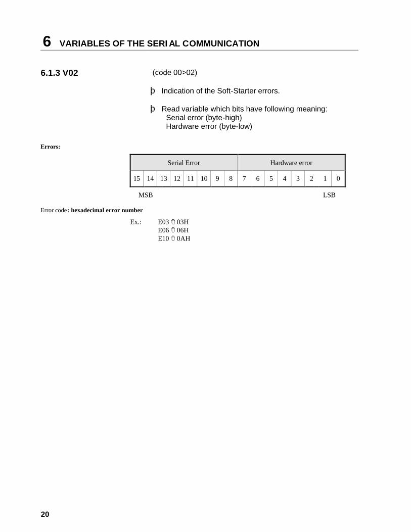
6.1.3 V02 (code 00>02) þ Indication of the Soft-Starter errors. þ Read variable which bits have following meaning:
Serial error (byte-high) Hardware error (byte-low)
Errors:
Serial Error Hardware error
15 14 13 12 11 10 9 8 7 6 5 4 3 2 1 0
MSB LSB
Error code: hexadecimal error number
Ex.: E03 Ü 03H E06 Ü 06H E10 Ü 0AH
VARIABLES OF THE SERIAL COMMUNICATION 6
21
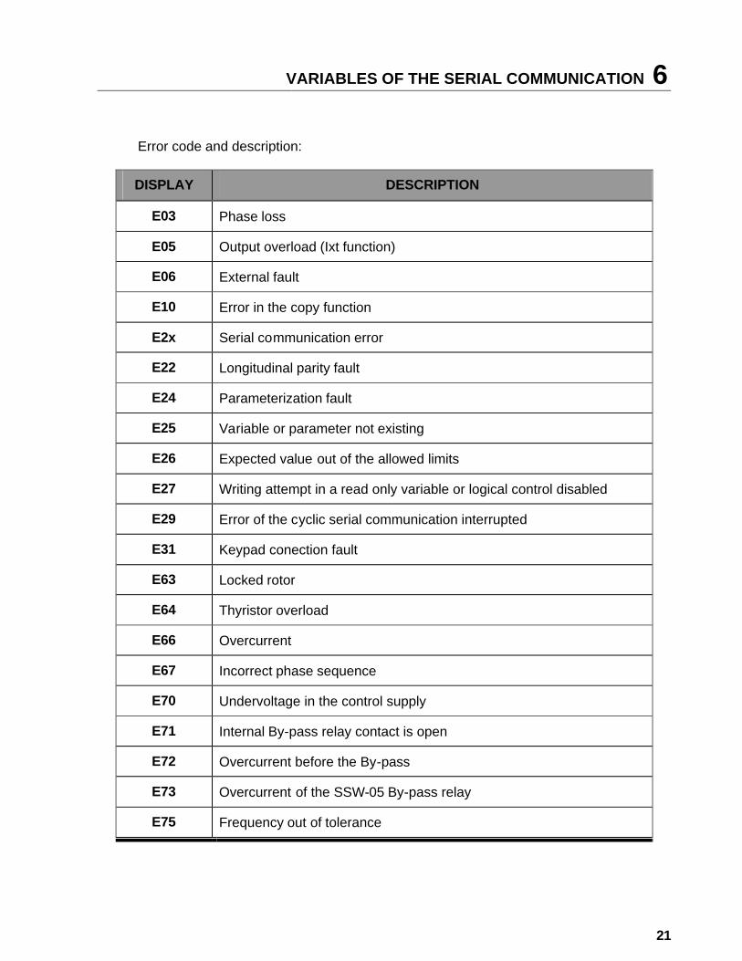
Error code and description: DISPLAY DESCRIPTION
E03 Phase loss
E05 Output overload (Ixt function)
E06 External fault
E10 Error in the copy function
E2x Serial communication error
E22 Longitudinal parity fault
E24 Parameterization fault
E25 Variable or parameter not existing
E26 Expected value out of the allowed limits
E27 Writing attempt in a read only variable or logical control disabled
E29 Error of the cyclic serial communication interrupted
E31 Keypad conection fault
E63 Locked rotor
E64 Thyristor overload
E66 Overcurrent
E67 Incorrect phase sequence
E70 Undervoltage in the control supply
E71 Internal By-pass relay contact is open
E72 Overcurrent before the By-pass
E73 Overcurrent of the SSW-05 By-pass relay
E75 Frequency out of tolerance
6 VARIABLES OF THE SERI AL COMMUNICATION
22
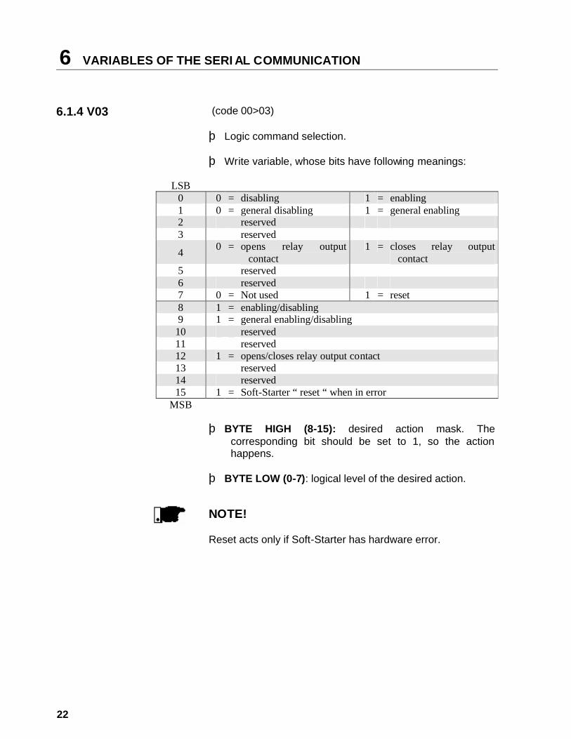
6.1.4 V03 (code 00>03)
þ Logic command selection. þ Write variable, whose bits have following meanings:
LSB 0 0 = disabling 1 = enabling 1 0 = general disabling 1 = general enabling 2 reserved 3 reserved
4 0 = opens relay output contact
1 = closes relay output contact
5 reserved 6 reserved 7 0 = Not used 1 = reset 8 1 = enabling/disabling 9 1 = general enabling/disabling
10 reserved 11 reserved 12 1 = opens/closes relay output contact 13 reserved 14 reserved 15 1 = Soft-Starter “ reset “ when in error
MSB
þ BYTE HIGH (8-15): desired action mask. The corresponding bit should be set to 1, so the action happens.
þ BYTE LOW (0-7): logical level of the desired action.
NOTE!
Reset acts only if Soft-Starter has hardware error.

ERROS E PARÂMETROS D A SERIAL 7
23
7.1 PARAMETERS RELATED TO
THE SERIAL COMMUNICATION
þ P264 - Commands via HMI and Serial or via Digital Inputs.
þ P308 – Address of the Soft-Starter at the communication network.
þ P313 – Action of the Serial Communication Verification. þ P314 – Time of the Serial Communication Verification.
7.2 ERRORS RELATED TO THE SERIAL COMMUNICATION
þ They do not disable WEG Soft-Starters; þ They do not disable the defective relay; þ They are informed in the word of the logical status. Fault Types: • E22: longitudinal parity fault (BCC); • E24: parameterization fault; • E25: variable or parameter not existing; • E26: expected value out of the permitted limits; • E27: writing attempt in a read only variable or logical
control disabled; • E29: error of the cyclic serial communication interrupted. Note: These errors can be noted by reading the status variable of WEG equipment. NOTE! The fault E29 can disable the Soft-Starters. This protection is used in installations, where the Soft-Starter has to take a decision in case of a communication fault between the master and the Soft-Starter. NOTE! Please take care of the function incompatibilities between the parameters as indicated in WEG Soft-Starter Manual.
8 DETAILED PARAMETER DESCRIPTION
24
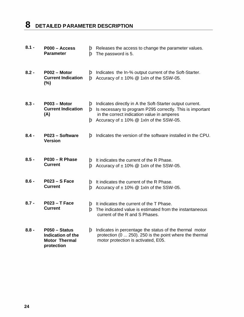
8.1 -
P000 – Access Parameter
þ Releases the access to change the parameter values. þ The password is 5.
8.2 -
P002 – Motor Current Indication (%)
þ Indicates the In-% output current of the Soft-Starter. þ Accuracy of ± 10% @ 1xIn of the SSW-05.
8.3 -
P003 – Motor Current Indication (A)
þ Indicates directly in A the Soft-Starter output current. þ Is necessary to program P295 correctly. This is important
in the correct indication value in amperes þ Accuracy of ± 10% @ 1xIn of the SSW-05.
8.4 -
P023 – Software Version
þ Indicates the version of the software installed in the CPU.
8.5 -
P030 – R Phase Current
þ It indicates the current of the R Phase. þ Accuracy of ± 10% @ 1xIn of the SSW-05.
8.6 -
P023 – S Face Current
þ It indicates the current of the R Phase. þ Accuracy of ± 10% @ 1xIn of the SSW-05.
8.7 -
P023 – T Face Current
þ It indicates the current of the T Phase. þ The indicated value is estimated from the instantaneous
current of the R and S Phases.
8.8 -
P050 – Status Indication of the Motor Thermal protection
þ Indicates in percentage the status of the thermal motor
protection (0 ... 250). 250 is the point where the thermal motor protection is activated, E05.
DETAILED PARAMETER DESCRIPTION 8
25
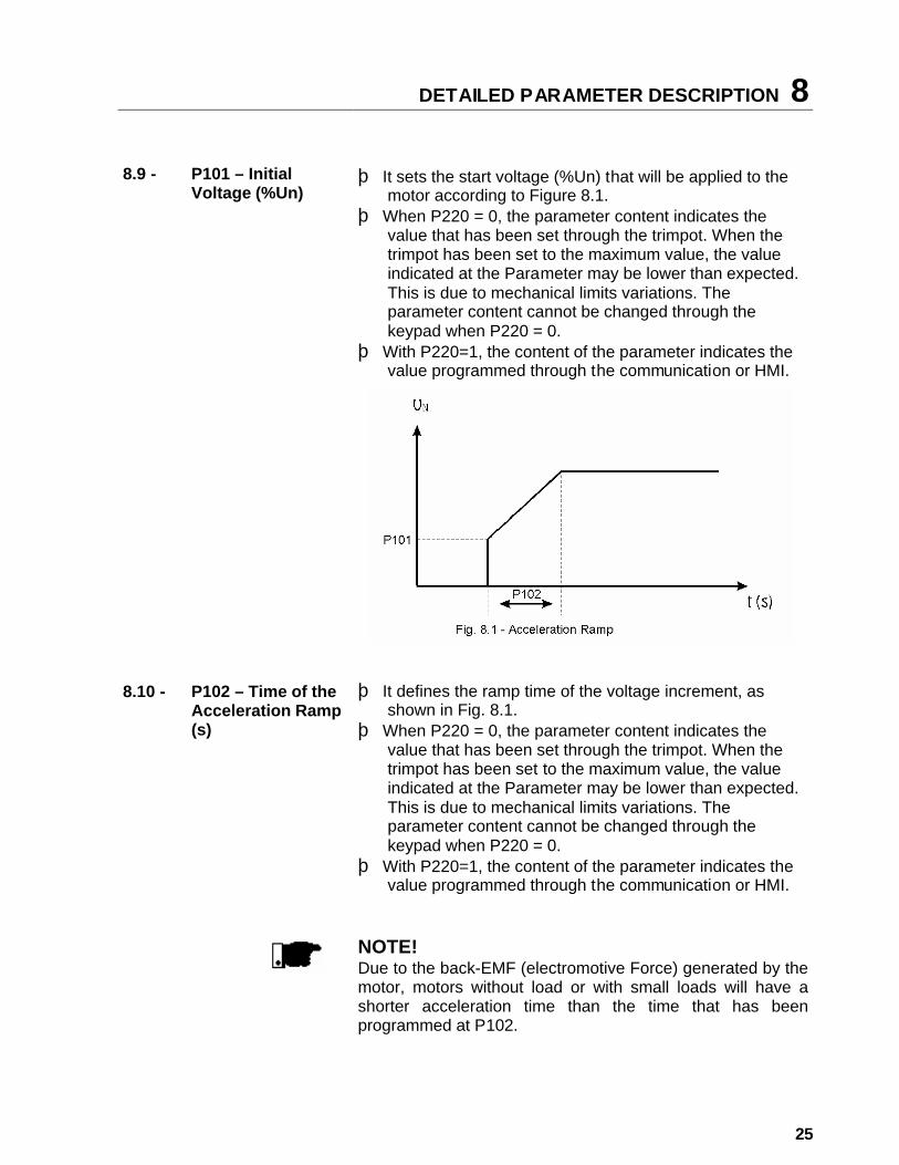
8.9 - P101 – Initial
Voltage (%Un) þ It sets the start voltage (%Un) that will be applied to the
motor according to Figure 8.1. þ When P220 = 0, the parameter content indicates the
value that has been set through the trimpot. When the trimpot has been set to the maximum value, the value indicated at the Parameter may be lower than expected. This is due to mechanical limits variations. The parameter content cannot be changed through the keypad when P220 = 0.
þ With P220=1, the content of the parameter indicates the value programmed through the communication or HMI.
8.10 -
P102 – Time of the Acceleration Ramp (s)
þ It defines the ramp time of the voltage increment, as
shown in Fig. 8.1. þ When P220 = 0, the parameter content indicates the
value that has been set through the trimpot. When the trimpot has been set to the maximum value, the value indicated at the Parameter may be lower than expected. This is due to mechanical limits variations. The parameter content cannot be changed through the keypad when P220 = 0.
þ With P220=1, the content of the parameter indicates the value programmed through the communication or HMI.
NOTE! Due to the back-EMF (electromotive Force) generated by the motor, motors without load or with small loads will have a shorter acceleration time than the time that has been programmed at P102.
8 DETAILED PARAMETER DESCRIPTION
26
8.11 -
P104 – Time of the Deceleration Ramp (s)
þ Used on pump application. þ Defines the ramp time of the voltage decrement þ When P220 = 0, the parameter content indicates the
value that has been set through the trimpot. When the trimpot has been set to the maximum value, the value indicated at the Parameter may be lower than expected. This is due to mechanical limits variations. The parameter content cannot be changed through the keypad when P220 = 0.
þ With P220=1, the content of the parameter indicates the value programmed through the communication or HMI.
NOTE! This function is used to delay the normal deceleration time of a load and in that way to not force a shorter time than that imposed by the own load.
8.12 -
P105 – Motor Current Setting (%)
þ It sets the motor current in percent relating to the rated Soft-Starter current. þ The indicated value is related directly to the activation
levels of the following motor protection devices: phase loss, overload, overcurrent and locked rotor.
þ When P220 = 0, the parameter content indicates the value that has been set through the trimpot. When the trimpot has been set to the maximum value, the value indicated at the Parameter may be lower than expected. This is due to mechanical limits variations. The parameter content cannot be changed through the keypad when P220 = 0.
þ With P220=1, the content of the parameter indicates the value programmed through the communication or HMI.
DETAILED PARAMETER DESCRIPTION 8
27
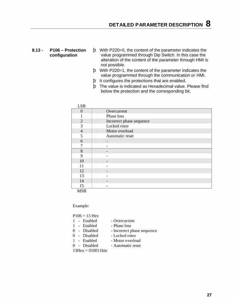
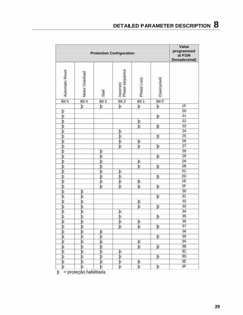
8.13 -
P106 – Protection configuration
þ With P220=0, the content of the parameter indicates the
value programmed through Dip Switch. In this case the alteration of the content of the parameter through HMI is not possible.
þ With P220=1, the content of the parameter indicates the value programmed through the communication or HMI.
þ It configures the protections that are enabled. þ The value is indicated as Hexadecimal value. Please find
below the protection and the corresponding bit.
LSB 0 Overcurrent 1 Phase loss 2 Incorrect phase sequence 3 Locked rotor 4 Motor overload 5 Automatic reset 6 - 7 - 8 - 9 - 10 - 11 - 12 - 13 - 14 - 15 -
MSB Example: P106 = 13 Hex 1 - Enabled 1 - Enabled 0 - Disabled 0 - Disabled 1 - Enabled 0 - Disabled 13Hex = 010011bin
- Overcurrent - Phase loss - Incorrect phase sequence - Locked rotor - Motor overload - Automatic reset
8 DETAILED PARAMETER DESCRIPTION
28
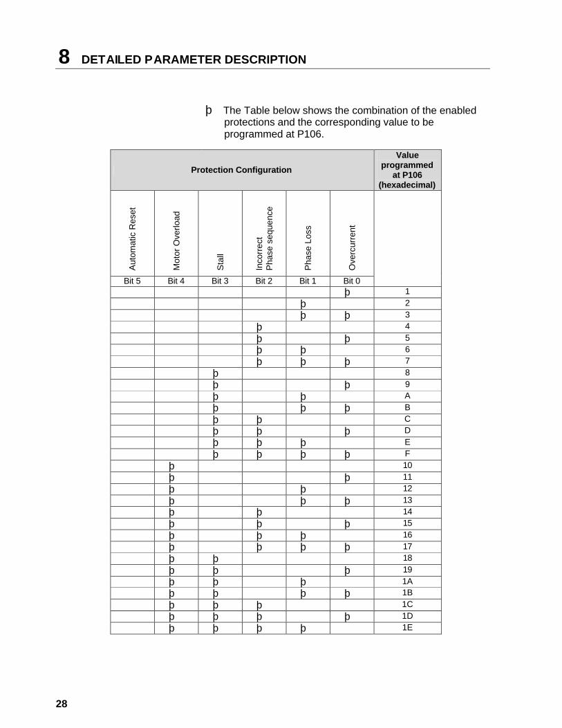
þ The Table below shows the combination of the enabled
protections and the corresponding value to be programmed at P106.
Protection Configuration Value
programmed at P106
(hexadecimal)
Aut
omat
ic R
eset
Mot
or O
verlo
ad
Sta
ll
Inco
rrec
t P
hase
seq
uenc
e
Pha
se L
oss
Ove
rcur
rent
Bit 5 Bit 4 Bit 3 Bit 2 Bit 1 Bit 0
þ 1 þ 2 þ þ 3 þ 4 þ þ 5 þ þ 6 þ þ þ 7 þ 8 þ þ 9 þ þ A þ þ þ B þ þ C þ þ þ D þ þ þ E þ þ þ þ F þ 10 þ þ 11 þ þ 12 þ þ þ 13 þ þ 14 þ þ þ 15 þ þ þ 16 þ þ þ þ 17 þ þ 18 þ þ þ 19 þ þ þ 1A þ þ þ þ 1B þ þ þ 1C þ þ þ þ 1D þ þ þ þ 1E
DETAILED PARAMETER DESCRIPTION 8
29
Protection Configuration
Value programmed
at P106 (hexadecimal)
Aut
omat
ic R
eset
Mot
or O
verlo
ad
Sta
ll
Inco
rrec
t P
hase
seq
uenc
e
Pha
se L
oss
Ove
rcur
rent
Bit 5 Bit 4 Bit 3 Bit 2 Bit 1 Bit 0
þ þ þ þ þ 1F þ 20 þ þ 21 þ þ 22 þ þ þ 23 þ þ 24 þ þ þ 25 þ þ þ 26 þ þ þ þ 27 þ þ 28 þ þ þ 29 þ þ þ 2A þ þ þ þ 2B þ þ þ 2C þ þ þ þ 2D þ þ þ þ 2E þ þ þ þ þ 2F þ þ 30 þ þ þ 31 þ þ þ 32 þ þ þ þ 33 þ þ þ 34 þ þ þ þ 35 þ þ þ þ 36 þ þ þ þ þ 37 þ þ þ 38 þ þ þ þ 39 þ þ þ þ 3A þ þ þ þ þ 3B þ þ þ þ 3C þ þ þ þ þ 3D þ þ þ þ þ 3E þ þ þ þ þ þ 3F
þ = proteção habilitada
8 DETAILED PARAMETER DESCRIPTION
30
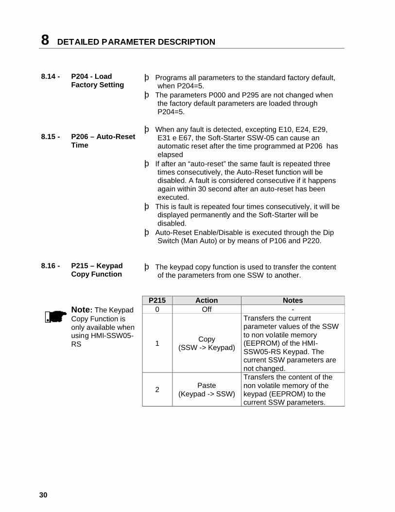
8.14 - P204 - Load
Factory Setting
þ Programs all parameters to the standard factory default, when P204=5.
þ The parameters P000 and P295 are not changed when the factory default parameters are loaded through P204=5.
8.15 -
P206 – Auto-Reset Time
þ When any fault is detected, excepting E10, E24, E29, E31 e E67, the Soft-Starter SSW-05 can cause an automatic reset after the time programmed at P206 has elapsed
þ If after an “auto-reset” the same fault is repeated three times consecutively, the Auto-Reset function will be disabled. A fault is considered consecutive if it happens again within 30 second after an auto-reset has been executed.
þ This is fault is repeated four times consecutively, it will be displayed permanently and the Soft-Starter will be disabled.
þ Auto-Reset Enable/Disable is executed through the Dip Switch (Man Auto) or by means of P106 and P220.
8.16 -
P215 – Keypad Copy Function
þ The keypad copy function is used to transfer the content
of the parameters from one SSW to another.
P215 Action Notes 0 Off -
1 Copy (SSW -> Keypad)
Transfers the current parameter values of the SSW to non volatile memory (EEPROM) of the HMI-SSW05-RS Keypad. The current SSW parameters are not changed.
Note: The Keypad Copy Function is only available when using HMI-SSW05-RS
2 Paste (Keypad -> SSW)
Transfers the content of the non volatile memory of the keypad (EEPROM) to the current SSW parameters.

DETAILED PARAMETER DESCRIPTION 8
31
þ Procedure is as follows: 1. Connect the keypad (HMI-SSW05-RS) to the inverter
from which the parameters will be copied (SSW A – source Soft-Starter).
2. Set P215=1 (copy) to transfer the parameter values from the SSW A to the keypad. Press key. During running of the copy function, display will show . P215 resets automatically to 0 (Off) after transfer has been completed.
3. Disconnect the keypad from the SSW (A). 4. Connect the same keypad to the SSW to which the
parameters will be transferred (SSW B – target Soft-Starter).
5. Set P215=2 (paste) to transfer the content of the keypad (EEPROM has the SSW A parameters) to SSW B. Press the key. While the keypad is running the paste function, the display shows , an abreviation for paste. When P215 returns to 0, the parameter transfer has been concluded. Now SSWs A and B will have the same parameter values.
To copy the parameter content of the SSW A to other
SSW(s), repeat steps 4 to 5 above.
Fig. 8.2 – Copying the parameters from the SSW A to the SSW B, by using the
Copy Function and the HMI-SSW05-RS keypad

8 DETAILED PARAMETER DESCRIPTION
32
8.17 -
P220 – HMI / (Trimpots and Dip Switch) Selection
þ It configures the operation mode of the Soft-Starter, in
“Trimpot and Dip Switch” mode or “HMI” mode. 0 - “(Trimpot and Dip Switch)” – the programming of the initial
voltage, ramp time, motor current setting and enabling of the protection devices is performed by means of the trimpots and dip switch. The values programmed through the serial communication is not used.
1 - “HMI” – the programming is performed through the serial
communication. The values programed through trimpots and dip switch is not used.
NOTE ! In “HMI” mode (P220=1) the trimpots and dip switch programming is ignored. The start voltage, ramp times, motor current setting and the protection enabling is programmed through the parameters P101, P102, P104, P105 and P106.
8.18 -
P264– Programmable Digital Input DI 1
þ It configures the DI 1 digital input to operate according to
the codes described below. 0 - “Not used”, DI 1 digital input is disabled. The enabling
commands are only accept via serial communication (V03).
1 - “Enable/Disable”, enabling only via digital input. The
enabling commands via serial communication are ignored.
2 - “External Fault”, it acts only if the DI 1 digital input is
open. It can also be used as additional load protection. Example: thermal protection of the motor through dry contact (without voltage) of a protection relay (Thermostat). The enabling commands are only accepted via serial communication (V03).

DETAILED PARAMETER DESCRIPTION 8
33
8.19 -
P277 – Programmable Relay Output (14/23 – 24)
þ It enables the relay (14/23 – 24) to operate according to
the following parameter setting: 1 - Function “Full voltage” – the relay closes the contact only
after the Soft-Starter reached 100% of Un (By-pass), and opens the contact when the Soft-Starter has received a switch-Off order.
2 - Function “Error”, the relay closes the NO contact when
the SSW-05 is with no error. 3 - Function “Logic Command”, the relay opens and closes
the relay contact according to the BIT 5 status of the V03 basic variable.
8.20 -
P295 – Rated Current of the Soft-Starter
þ Configures the SSW-05 models. þ Its function is to set the software so the current indication
in Ampere (P003) is correct. The possible configurations of the SSW-05 model are: 0 = 3A 1 = 10A 2 = 16A 3 = 23A 4 = 30A 5 = 45A 6 = 60A 7 = 85A
8.21 -
P308 - Network Address
þ It defines the address at which the Soft-Starter will
respond on the communication network between all equipment connected to this network.
8 DETAILED PARAMETER DESCRIPTION
34
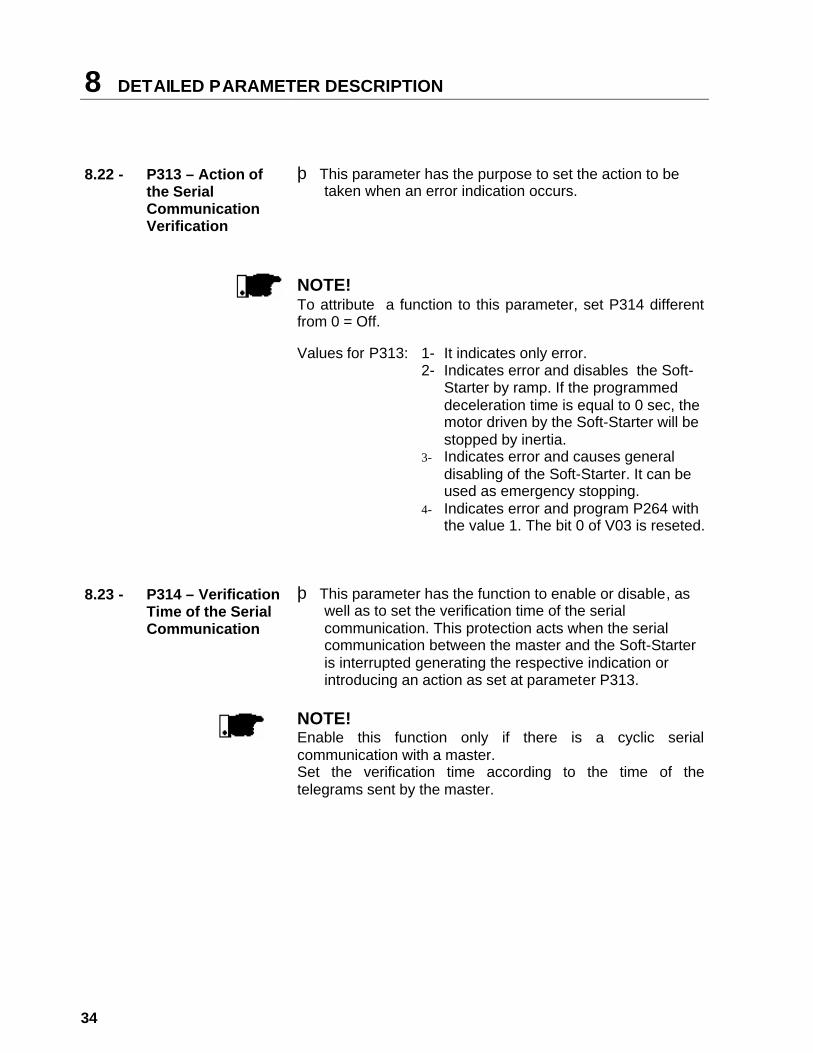
8.22 -
P313 – Action of the Serial Communication Verification
þ This parameter has the purpose to set the action to be
taken when an error indication occurs.
NOTE! To attribute a function to this parameter, set P314 different from 0 = Off.
Values for P313: 1- It indicates only error. 2- Indicates error and disables the Soft-
Starter by ramp. If the programmed deceleration time is equal to 0 sec, the motor driven by the Soft-Starter will be stopped by inertia.
3- Indicates error and causes general disabling of the Soft-Starter. It can be used as emergency stopping.
4- Indicates error and program P264 with the value 1. The bit 0 of V03 is reseted.
8.23 -
P314 – Verification Time of the Serial Communication
þ This parameter has the function to enable or disable, as
well as to set the verification time of the serial communication. This protection acts when the serial communication between the master and the Soft-Starter is interrupted generating the respective indication or introducing an action as set at parameter P313.
NOTE! Enable this function only if there is a cyclic serial communication with a master. Set the verification time according to the time of the telegrams sent by the master.
TROUBLESHOOTING 9
35
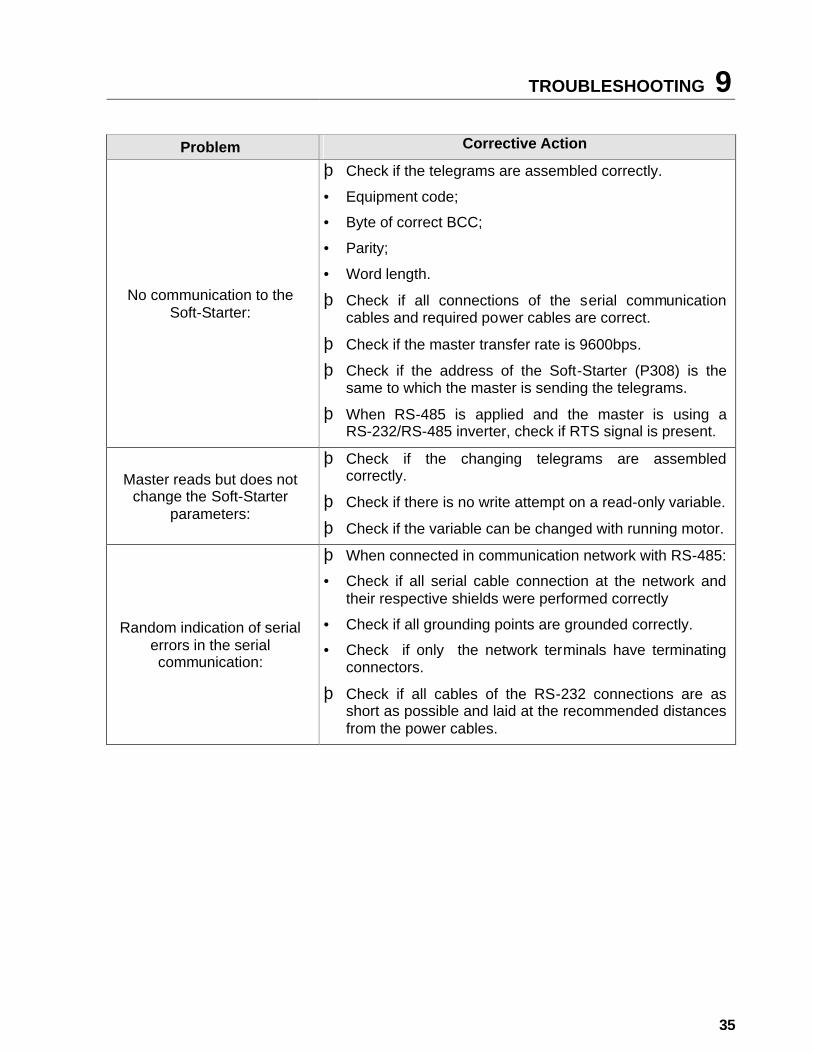
Problem Corrective Action
No communication to the Soft-Starter:
þ Check if the telegrams are assembled correctly.
• Equipment code;
• Byte of correct BCC;
• Parity;
• Word length.
þ Check if all connections of the serial communication cables and required power cables are correct.
þ Check if the master transfer rate is 9600bps.
þ Check if the address of the Soft-Starter (P308) is the same to which the master is sending the telegrams.
þ When RS-485 is applied and the master is using a RS-232/RS-485 inverter, check if RTS signal is present.
Master reads but does not change the Soft-Starter
parameters:
þ Check if the changing telegrams are assembled correctly.
þ Check if there is no write attempt on a read-only variable.
þ Check if the variable can be changed with running motor.
Random indication of serial errors in the serial communication:
þ When connected in communication network with RS-485:
• Check if all serial cable connection at the network and their respective shields were performed correctly
• Check if all grounding points are grounded correctly.
• Check if only the network terminals have terminating connectors.
þ Check if all cables of the RS-232 connections are as short as possible and laid at the recommended distances from the power cables.