Embed Size (px)
Citation preview
1
Serial Number: _______________________________
Model Number: ___________________________
Contract No.: _______________________________
Date: _______________________________
Instruction, Operation, and Maintenance Manual
Fulton Oil Fired/Gas Fired Steam Boilers
4 HP to 150 HP
Instruction
2
This manual is provided as a guide to the correct operation and maintenance of your Fulton Oil Fired/Gas Fired Boiler, and should be permanently available to the staff responsible for the operation of the boiler.
These instructions must not be
considered as a complete code of
practice, nor should they replace existing
codes or standards that may be
applicable.
The requirements and instructions
contained in this section generally relate
to the standard Fulton Oil Fired/Gas
Fired steam Boiler. When installing a
packaged unit, this entire section should
be read carefully to ensure that the
installation work is carried out correctly.
Prior to shipment the following high
standard tests are made to assure the
customer has the highest quality of
manufacturing:
a) Material inspections.
b) Manufacturing process inspections.
c) ASME welding inspections.
d) ASME hydrostatic test inspection.
e) Electrical components inspection.
f) Operating test.
g) Final Inspection.
h) Crating inspection.
All units can be transported with forklift.
Under no circumstances should weight
be allowed to bear on the jacket, control
panel, or fan housing of any Fulton
Boiler.
The customer should examine the boiler
for any damage, especially the refractory
Rigging your boiler into position should
be handled by a experienced in handling
heavy equipment
Contents
3
Section
Safety Warnings Cautions Notes
Description/Instructions
Specifications & Dimensions 4HP-150 HP
Locating the Boiler
The Fuel Oil Supply
The Gas Supply
Boiler, Condensate Tank, and Blow off Separator Piping
Boiler Installation
Water Supply
Glossary of Water Treatment
Electrical Requirements
Fresh Air Supply for Boiler Room
Conventional Venting
Exhaust Side Wall Venting
Combustion Air Intake
Corrosion of Flue Pipe
Installation Checkpoints
Cleaning the Pressure Vessel Operation
Starting the Boiler
Oil Burner Set Up
Gas Burner Set Up
Primary Air Adjustment
Secondary Air Adjustment
Boiler Controls Maintenance
Procedure for Cleaning Water Probes
Flame Rod Adjustment
Flame Scanner Adjustment
Checking Stainless Steel Combustion Ring
Furnace Refractory Replacement Procedure
Recommend daily Maintenance
Recommend Weekly Maintenance
Recommend Monthly Maintenance
Recommend Semi Annual Maintenance
Recommend Annual Maintenance
Trouble shooting
Parts
Oil Burner and Ignition Assembly Components
Gas Burner and Ignition Assembly Components
Sketch of Layout for Boiler Room Warranty
Files Card for Fulton Boiler Users
Guarantee Card of Fulton Boiler
1 2
3
4
6
5

Safety Warnings Cautions & Notes
4
Safety Warnings Cautions & Notes
5
Safety Warnings, Cautions &
Notes
The following WARNINGS,
CAUTIONS, and NOTES appear in
various chapters of this manual.
They are repeated on these safety
summary pages as an example and
for emphasis.
WARNINGS must be observed to
prevent serious injury or death to
personnel.
CAUTIONS must be observed to
prevent damage or destruction of
equipment or loss of operating
efficiency.
NOTES must be observed to keep
boiler being operated with high
efficiency.
It is the responsibility and duty of all
personnel involved in the operation
and maintenance of this equipment
to fully understand the WARNINGS,
CAUTIONS, and NOTES by which
hazards are to be reduced or
eliminated. Personnel must become
thoroughly familiar with all aspects
of safety and equipment prior to
operation or maintenance of the
equipment.
CAUTION
Some matters used for leak testing
are corrosive to certain types of
metals. Rinse all piping thoroughly
with clean water after leak check
has been completed.
NOTE
Where a return tank is to be fitted,
this should:
1. Be vented and
2. Have a capacity sufficient to
satisfy boiler consumption as
well as maintain proper return
tank temperature.
3. Vent pipe should not be
downsized (This may cause
pressure build up in the
condensate tank).
4. Return pipes must not be
insulated. This can cause
overheating the return system,
causing a vapor lock in the pump.
5. See Return System Instruction
Manual for detailed instructions.
NOTE
Care should be taken to ensure
that the blow off receptacle used
meets the regulations covering
such vessels. If in doubt consult
Fulton for a advice.
NOTE
Only properly trained personnel
should install and maintain water
gauge glass and connections.
Wear safety glasses during
installation. Before installing,
make sure all parts are free of
chips and debris.
NOTE
Keep gauge glass in original
packaging until ready to install.
WARNING
Improper installation or
maintenance of gauge glass and
connections can cause
immediate or delayed breakage
resulting in bodily injury and /or
property damage.
NOTE
After installation is completed
and prior to operation the
pressure vessel should cleaned.
CAUTION
Do not store halogenated
hydrocarbons near or in the
boiler room.
NOTE
a) The fused disconnect switch
that controls the feed water
pump should be kept in the
“on’ position at all times
during the boiler operation as
well as during the
non-operating period of the
boiler.
b) This switch should be turned
“off” only when repairs or
adjustments should be made.
NOTE
The pump will continue to
operate until the water reaches
the correct level in the boiler. This
level is approximately the center
of the water gauge glass.
WARNING
Prior to the commencement of
any work requiring the removal of
cover plates and the opening of
the control panel box, the
electrical supply to the boiler
must be disconnected.
CAUTION
Do not tamper with the safety
features of the low water safety
cut off.
CAUTION
When stopping the boiler for any
extensive repairs, shut off main
disconnect switches on both the
boiler side as well as the feed
water side.
NOTE
To ensure that your Fulton Steam
Boiler is kept operating safely
and efficiently, follow the
maintenance procedures set froth
in Section 4 of this manual.
Safety Warnings Cautions & Notes
6
NOTE
The flame scanner is located on
the outside edge of the burner
top plate for 20HP-150HP.
NOTE
If the boiler is being operated
automatically on a time clock,
the blow off operation may be
done once before boiler is
operated during the working day
and once at the end of the day
(when at 10 PSIG).
NOTE
Fulton recommends that feed
water treatment should be
performed before it is added into
the boiler.
WARNING
Make sure main power switch is
off before starting work.
CAUTION
Do not clean the gauge or glass
while pressurized or in
operation.
NOTE
After a new Fulton Boiler has
been in operation for several
months, pieces of burned metal
will be found in the space at the
bottom of the boiler. These
pieces of metal act as the formed
combustion ring effect during
manufacture. This is a normal
condition and does not affect the
efficiency and the life of the
boiler in any way.

Description/Instruction
7
Description/Instruction
8
Description/Instruction
9
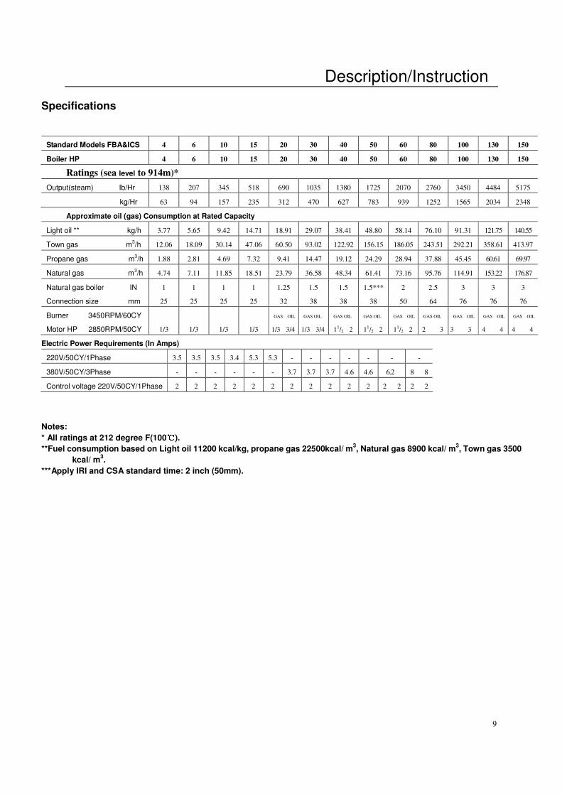
Specifications
Standard Models FBA&ICS 4 6 10 15 20 30 40 50 60 80 100 130 150
Boiler HP 4 6 10 15 20 30 40 50 60 80 100 130 150
Ratings (sea level to 914m)*
Output(steam) Ib/Hr 138 207 345 518 690 1035 1380 1725 2070 2760 3450 4484 5175
kg/Hr 63 94 157 235 312 470 627 783 939 1252 1565 2034 2348
Approximate oil (gas) Consumption at Rated Capacity
Light oil ** kg/h 3.77 5.65 9.42 14.71 18.91 29.07 38.41 48.80 58.14 76.10 91.31 121.75 140.55
Town gas m3/h 12.06 18.09 30.14 47.06 60.50 93.02 122.92 156.15 186.05 243.51 292.21 358.61 413.97
Propane gas m3/h 1.88 2.81 4.69 7.32 9.41 14.47 19.12 24.29 28.94 37.88 45.45 60.61 69.97
Natural gas m3/h 4.74 7.11 11.85 18.51 23.79 36.58 48.34 61.41 73.16 95.76 114.91 153.22 176.87
Natural gas boiler IN 1 1 1 1 1.25 1.5 1.5 1.5*** 2 2.5 3 3 3
Connection size mm 25 25 25 25 32 38 38 38 50 64 76 76 76
Burner 3450RPM/60CY GAS OIL GAS OIL GAS OIL GAS OIL GAS OIL GAS OIL GAS OIL GAS OIL GAS OIL
Motor HP 2850RPM/50CY 1/3 1/3 1/3 1/3 1/3 3/4 1/3 3/4 11/2 2 1
1/2 2 1
1/2 2 2 3 3 3 4 4 4 4
Electric Power Requirements (In Amps)
220V/50CY/1Phase 3.5 3.5 3.5 3.4 5.3 5.3 - - - - - - -
380V/50CY/3Phase - - - - - - 3.7 3.7 3.7 4.6 4.6 6.2 8 8
Control voltage 220V/50CY/1Phase 2 2 2 2 2 2 2 2 2 2 2 2 2 2 2
Notes:
* All ratings at 212 degree F(100℃℃℃℃).
**Fuel consumption based on Light oil 11200 kcal/kg, propane gas 22500kcal/ m3, Natural gas 8900 kcal/ m
3, Town gas 3500
kcal/ m3.
***Apply IRI and CSA standard time: 2 inch (50mm).
Description/Instruction
10
Description/Instruction
11
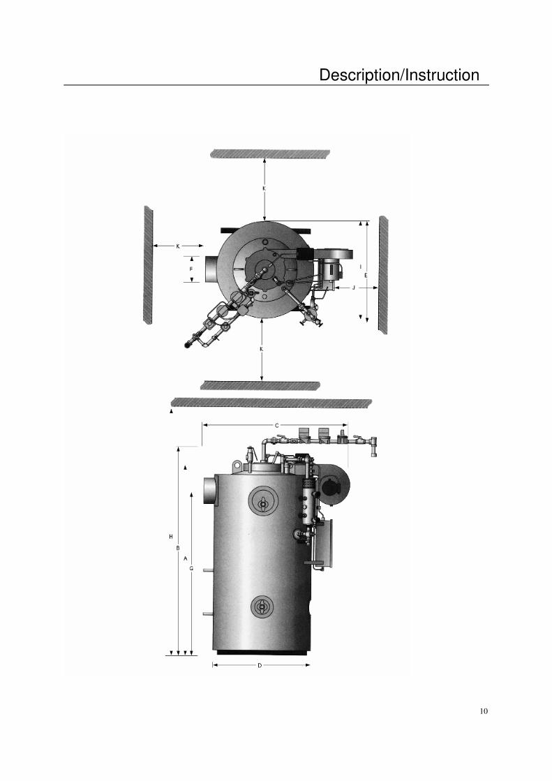
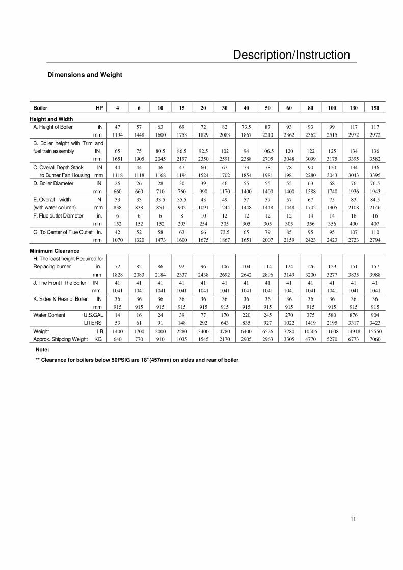
Dimensions and Weight
Boiler HP 4 6 10 15 20 30 40 50 60 80 100 130 150
Height and Width
A. Height of Boiler iN 47 57 63 69 72 82 73.5 87 93 93 99 117 117
mm 1194 1448 1600 1753 1829 2083 1867 2210 2362 2362 2515 2972 2972
B. Boiler height with Trim and
fuel train assembly IN 65 75 80.5 86.5 92.5 102 94 106.5 120 122 125 134 136
mm 1651 1905 2045 2197 2350 2591 2388 2705 3048 3099 3175 3395 3582
C. Overall Depth Stack IN 44 44 46 47 60 67 73 78 78 90 120 134 136
to Burner Fan Housing mm 1118 1118 1168 1194 1524 1702 1854 1981 1981 2280 3043 3043 3395
D. Boiler Diameter IN 26 26 28 30 39 46 55 55 55 63 68 76 76.5
mm 660 660 710 760 990 1170 1400 1400 1400 1588 1740 1936 1943
E. Overall width IN 33 33 33.5 35.5 43 49 57 57 57 67 75 83 84.5
(with water column) mm 838 838 851 902 1091 1244 1448 1448 1448 1702 1905 2108 2146
F. Flue outlet Diameter in. 6 6 6 8 10 12 12 12 12 14 14 16 16
mm 152 152 152 203 254 305 305 305 305 356 356 400 407
G. To Center of Flue Outlet in.
mm
42
1070
52
1320
58
1473
63
1600
66
1675
73.5
1867
65
1651
79
2007
85
2159
95
2423
95
2423
107
2723
110
2794
Minimum Clearance
H. The least height Required for
Replacing burner in. 72 82 86 92 96 106 104 114 124 126 129 151 157
mm 1828 2083 2184 2337 2438 2692 2642 2896 3149 3200 3277 3835 3988
J. The Front f The Boiler IN 41 41 41 41 41 41 41 41 41 41 41 41 41
mm 1041 1041 1041 1041 1041 1041 1041 1041 1041 1041 1041 1041 1041
K. Sides & Rear of Boiler IN 36 36 36 36 36 36 36 36 36 36 36 36 36
mm 915 915 915 915 915 915 915 915 915 915 915 915 915
Water Content U.S.GAL 14 16 24 39 77 170 220 245 270 375 580 876 904
LITERS 53 61 91 148 292 643 835 927 1022 1419 2195 3317 3423
Weight LB 1400 1700 2000 2280 3400 4780 6400 6526 7280 10506 11608 14918 15550
Approx. Shipping Weight KG 640 770 910 1035 1545 2170 2905 2963 3305 4770 5270 6773 7060
Note:
** Clearance for boilers below 50PSIG are 18”(457mm) on sides and rear of boiler
Description/Instruction
12
Locating the Boiler
a) The boiler should be located in
dry surroundings on a level base,
making sure that there is sufficient
room around the boiler to enable the
operator and/or the maintenance
engineer to gain access to all parts
of the boiler. Check location for ease
of water supply and electrical
connections.
b) Place the boiler on a
noncombustible floor with clearances
to unprotected combustible materials,
including plaster or combustible
supports.
c) It is necessary to have the
sufficient clearance from the floor to
the ceiling for removal of the burner.
The Fuel Oil Supply
a) Be sure that the oil supply lines
from the tank to the burner are of
proper size. Vacuum should not
exceed 10” of mercury at the oil
pump inlet.
b) All Fulton oil burners are of the two
pass design system requiring a return
line and supply line. The oil pump is
factory set at 230 psi (=16 Kg/cm2).
Do not change this setting without
allowance of Fulton Boiler..
c) A stop valve, a check valve, and an
oil filter must be installed in the oil
supply line.
d) When one oil line is feeding two
burners, a check valve must be
installed in each unit.
e) Make sure there are no loose
fittings. Loose fittings in the fuel oil
line will allow air to enter into the fuel
line and cause improper firing.
The Gas Supply
a) Gas piping should be installed in
accordance with National Fuel Gas
Code, and any other local codes
which may apply.
b) Install a dirt trap ahead of all of the
gas valves.
c) The pipe and the fittings used must
be new and free of dirt or other
deposits.
d) The piping must be of the proper
size to ensure adequate gas supply
to the gas head assembly. Consult
your gas company for specific
recommendations.
e) For natural gas a pressure of 7” to
11” (178mm to 279mm) of water
column pressure at the gas train is
required with burner firing. Do not
exceed 13” of water column.
f) For propane or butane gas the
pressure required is 11”(279mm) of
water column pressure. Again, do not
exceed 13” of water column.
g) When making gas piping joints,
use a compound to seal the gas line
treads. Do not use Teflon tape on gas
line threads.
h) The main and the pilot gas
pressure regulators must be vented
to the atmosphere.
i) After gas piping is completed
carefully check all piping connections,
for gas leaks. Use a soap and water
solution.
Caution
Some matters used for leak testing
are corrosive to certain types of
metals. Rinse all piping thoroughly
with clean water after leak check
has been completed.
j) The boiler must be disconnected at
the boiler shut off valve from the gas
supply piping system when intake
gas pressure is in excess of
14”W.C.
k) The boiler must be isolated from
the gas supply piping system by
closing the shutoff cock during any
pressure testing of the gas supply
piping system at pressure equal to or
less than 1/2 PSIG-14”W.C.
Description/Instruction
13
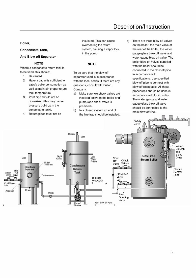
Boiler,
Condensate Tank,
And Blow off Separator
NOTE
Where a condensate return tank is
to be fitted, this should:
1. Be vented.
2. Have a capacity sufficient to
satisfy boiler consumption as
well as maintain proper return
tank temperature.
3. Vent pipe should not be
downsized (this may cause
pressure build up in the
condensate tank).
4. Return pipes must not be
insulated. This can cause
overheating the return
system, causing a vapor lock
in the pump
NOTE
To be sure that the blow off
separator used is in accordance
with the local codes. If there are any
questions, consult with Fulton
Company.
a) Make sure two check valves are
installed between the boiler and
pump (one check valve is
pre-fitted).
b) In a closed system an end of
the line trap should be installed.
c) There are three blow off valves
on the boiler, the main valve at
the rear of the boiler, the water
gauge glass blow off valve and
water gauge blow off valve. The
boiler blow off valves supplied
with the boiler should be
connected to the blow off pipe
in accordance with
specifications. Use specified
blow off pipe to connect with
blow off receptacle. All these
procedures should be done in
accordance with local codes.
The water gauge and water
gauge glass blow off valve
should be connected to the
main blow off line.
To boiler Feedwater A A
Joint Blow off Pipe B B

Description/Instruction
14
Boiler Installation
The Steam Supply—Pipe the
steam supply line from the top right
side of the boiler.
The Steam Safety Valve
1) Before installing, be sure that
all pipes and connections have
been blown clean. Pipe sealing
dope is used on external
threads only. Be sure inlet of
valve is free of any foreign
material to avoid leakage of
safety valve.
2) Do not use a pipe wrench.
When making installation, use
proper type and size wrench.
3) The valve should be installed in
a vertical upright position in the
connection provided on the top
left side of the boiler .Under no
circumstances should there be
a shut off valve or restriction of
any kind between the safety
valve and the connection
provided.
4) Do not cap or plug drain hole in
the side of valve body.
5) Since the purpose of this safety
valve is to protect against an
overpressure situation, it will
loudly discharge hot steam in
doing so. Therefore, it is
recommended that a discharge
pipe be securely installed and
run to a safe point disposal.
6) When a discharge pipe is used,
it must be of a pipe size equal
to or greater than that of the
valve outlet. Use pipe with
sufficient strength, extra strong or
double extra strong discharge pipe
or connections, and it should be
short and straight as far as possible
to reduce the pressure on safety
valve. It must have an ample
provision for draining condensate at
or near the valve outlet. It must
terminate freely to atmosphere and
maintain normal atmosphere
pressure (no pressure difference
with outside).
The Steam Pressure Gauge
Assembly
The gauge should be facing front
towards the panel box and /or
operator of the boiler. Except as
noted, each assembly or any of its
component parts may be oriented,
other than shown to provide
improved operating clearance and
/or view of gauge. Before installing
steam gauge on the siphon, add a
small amount of distillate to the
gauge element for sealing. This
must be completed to prevent
inaccurate pressure readings and
/or
Description/Instruction
15
premature failure of the gauge.
Install the steam gauge into the
siphon on the water column.
The Blow-off Valve
There are three blow off valves on
the boiler, the main valve at the
rear of the boiler ,the water gauge
glass blow off valve and water lever
blow off valve. The boiler blow off
valves supplied with the boiler
should be connected to the blow off
pipe in accordance with
specifications, Use specified blow
off pipe to connect with blow off
receptacle. All these procedures
should be done in accordance with
local codes.
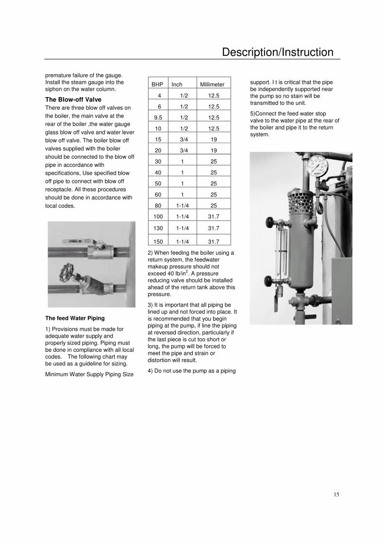
The feed Water Piping
1) Provisions must be made for
adequate water supply and
properly sized piping. Piping must
be done in compliance with all local
codes. The following chart may
be used as a guideline for sizing.
Minimum Water Supply Piping Size
2) When feeding the boiler using a
return system, the feedwater
makeup pressure should not
exceed 40 lb/in2. A pressure
reducing valve should be installed
ahead of the return tank above this
pressure.
3) It is important that all piping be
lined up and not forced into place. It
is recommended that you begin
piping at the pump, if line the piping
at reversed direction, particularly if
the last piece is cut too short or
long, the pump will be forced to
meet the pipe and strain or
distortion will result.
4) Do not use the pump as a piping
support. I t is critical that the pipe
be independently supported near
the pump so no stain will be
transmitted to the unit.
5)Connect the feed water stop
valve to the water pipe at the rear of
the boiler and pipe it to the return
system.
BHP Inch Millimeter
4 1/2 12.5
6 1/2 12.5
9.5 1/2 12.5
10 1/2 12.5
15 3/4 19
20 3/4 19
30 1 25
40 1 25
50 1 25
60 1 25
80 1-1/4 25
100 1-1/4 31.7
130 1-1/4 31.7
150 1-1/4 31.7
Description/Instruction
16
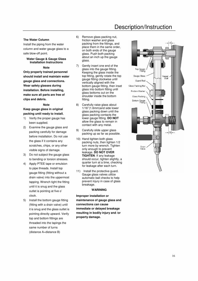
The Water Column
Install the piping from the water
column and water gauge glass to a
safe blow-off point.
Water Gauge & Gauge Glass Installation Instructions
Note
Only properly trained personnel
should install and maintain water
gauge glass and connections.
Wear safety glasses during
installation. Before installing,
make sure all parts are free of
clips and debris.
Note
Keep gauge glass in original
packing until ready to install.
1) Verify the proper gauge has
been supplied.
2) Examine the gauge glass and
packing carefully for damage
before installation. Do not use
the glass if it contains any
scratches, chips, or any other
visible signs of damage.
3) Do not subject the gauge glass
to bending or torsion stresses.
4) Apply PTEE tape or emulsion
to pipe threads. Install top
gauge fitting (fitting without a
drain valve) into the uppermost
tapping. Wrench tight the fitting
until it is snug and the glass
outlet is pointing at five o’
clock.
5) Install the bottom gauge fitting
(fitting with a drain valve) until
it is snug and the glass outlet is
pointing directly upward. Verify
top and bottom fittings are
threaded into the tapings the
same number of turns
(distance A=distance B)
6) Remove glass packing nut, friction washer and glass packing from the fittings, and place them in the same order, on both ends of the gauge glass. Push both packing about an inch up the gauge glass.
7) Gently insert one end of the glass into the gauge fitting. Keeping the glass inside the top fitting, gently rotate the top gauge fitting clockwise until vertically aligned with the bottom gauge fitting, then inset glass into bottom fitting until glass bottoms out on the shoulder inside the bottom fitting.
8) Carefully raise glass about 1/16’’(1.6mm)and side lower glass packing down until the glass packing contacts the lower gauge fitting. DO NOT allow the glass to remain in contact with any metal.
9) Carefully slide upper glass packing up as far as possible.
10) Hand tighten both glass packing nuts, then tighten 1/2 turn more by wrench. Tighten only enough to prevent leakage. DO NOT OVER TIGHTEN. If any leakage should occur, tighten slightly, a quarter turn at a time, checking for leakage after each turn.
11) Install the protective guard. Gauge glass valves utilize automatic ball checks to help prevent injury in case of glass breakage.
WARINING
Improper installation or
maintenance of gauge glass and
connections can cause
immediate or delayed breakage
resulting in bodily injury and /or
property damage.
Description/Instruction
17
Water supply
a)Feed water contains
solids and dissolved gases.
These may promote
incrustation of scale;
corrosion etc.. To prevent
this, feed water must be
studied individually and
treated accordingly by
reputable professionals
specializing in this field.
It is strongly recommended
that a competent water
treatment specialist be
consulted prior to the
installation of the boiler.
b)The purpose of this
treatment should be to
provide quality feed water
to the boiler such that
corrosion and deposition in
the boiler will be minimized.
Dissolved oxygen, high
chloride levels and low PH
can all be major causes of
corrosion. Untreated
hardness is the major
cause of deposits. Poor
quality feed water requires
increased blow off and
increased chemical
treatment costs to prevent
boiler corrosion and
scaling.
c)One way to lower the
amount of dissolved
oxygen in the boiler feed
water is the sparge tube
option. This option injects
live steam into the feed
water to increase the water
temperature to 82 degrees
C which remove oxygen
from the water.
d)Chlorides can be
controlled by increasing
the number of blow down
per day from one to four.
e)The Fulton warranty
does not cover damage or
failure that can be
attributed to corrosion,
scale or dirt accumulations.
Oxygen is a corrosive. See
the Warranty Section of
this manual for full details.
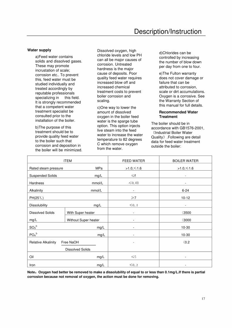
Recommended Water Treatment
The boiler should be in
accordance with GB1576-2001, 《Industrial Boiler Water
Quality》.Following are detail
data for feed water treatment
outside the boiler:
Note::::Oxygen had better be removed to make a dissolubility of equal to or less than 0.1mg/L.If there is partial
corrosion because not removal of oxygen, the action must be done for removing.
ITEM FEED WATER BOILER WATER
Rated steam pressure MPa >1.0,≤1.6 >1.0,≤1.6
Suspended Solids mg/L ≤5 -
Hardness mmol/L ≤0.03 -
Alkalinity mmol/L - 6-24
PH(25℃) ≥7 10-12
Dissolubility mg/L ≤0.1 -
With Super heater - 〈3500 Dissolved Solids
mg/L Without Super heater - 〈3000
SO32-
mg/L - 10-30
PO43-
mg/L - 10-30
Relative Alkalinity Free NaOH
Dissolved Solids
- 〈0.2
Oil mg/L ≤2 -
Iron mg/L ≤0.3 -
Description/Instruction
18
Glossary of Water Supply Dissolved Oxygen: Oxygen that is dissolved in the feed water will cause the steel in the boiler and the feed water system to be attacked by the water in a manner described as “pitting”. The pits that are produced can vary from tiny depressions to holes large enough to penetrate the boiler metal and are usually covered with tubercles of iron oxide. Once pitting starts, it may be extremely hard to arrest. Pitting can proceed at a surprisingly rapid rate and can occur not only in the boiler proper, but also in pre-boiler equipment such as economizers, feed water heaters, and feed water lines. Sodium Sulfite Its purpose is to chemically remove the dissolved oxygen left in the feed water. Sodium Sulfite reacts chemically with dissolved oxygen, producing sodium sulfate. Since it is desirable to remove dissolved oxygen from the feed water before it reaches a boiler. Sodium sulfite is best introduced continuously at some suitable point in the feed water system (the storage section of the feed water heater, six inches below the water line). Chemical residual control is based on the maintenance of a specific excess of sodium sulfite in the boiler water. The essential requirement being to maintain in the feed water at all times slightly more than enough sodium sulfite to consume all of the dissolved oxygen. When sodium sulfite is not fed continuously, protection of the boiler against oxygen attack must depend on the reserve of sodium sulfite that is present in the boiler water. In this case, it
is important that the feed water and the boiler water are mixed thoroughly and as quickly as possible so that boiler water sodium sulfite may consume feed water oxygen before the latter can cause damage to the boiler. Sulfite as a treatment represents a second line of defense against oxygen corrosion. A vigorous maintenance program to safe guard against oxygen leakage into the pre-boiler system should be followed. Suspended Solids: Suspended solids are the undissolved matter in water, including dirt, silt vegetation, and any other insoluble organic matter. Normally suspended solids are expressed in terms of turbidity. The presence of suspended solids in cooling water can increase impingement type corrosion. Suspended solids may also deposit in low velocity areas and create differential aeration cells. Pitting can result. The most common cause of high suspended solids is high hardness feed water. Of the agents which cause foaming, suspended solids probably have the least effect. Reasons for the increased hardness or other suspended solids should be determined. In line filters or various types of pretreatment can be used to lower the suspended solids level. Various polymers assist in holding solids in suspension. Alkalinity: Alkalinity is the capacity of a water to neutralize acids. Common water alkalinities consist of bicarbonate, carbonates, hydroxide, phosphate, and silicate. These alkalinities, especially bicarbonates and
carbonates, break down to form carbon dioxide in steam, which is a major factor in the corrosion on condensate lines. High alkalinity also causes foaming and carries over in boilers. Both foaming and carry over cause erratic boiler operation. When foaming occurs an anti-foam should be added or increased. The reason for the high alkalinity should be determined. It may result from lack of sufficient blow off. Pretreated makeup water and condensate should also be checked. Quite often the source of alkalinity is an overdose of alkaline internal water treatment chemical. pH: pH is a measure of the degree of acid or base of solution. Normal pH ranges of 6.5-9.0 will have little influence on the corrosion rate of cooling waters. If for some reason— pollution, etc.—the pH is lowered into the acid range, increased corrosion can be expected. The solution lies in determining the cause of the low pH and correcting that condition. A low pH can result in corrosion of metals, while a high pH can result in scale formation. In order to control boilers and equipment used for the external treatment of make up water, it is essential that reliable pH measurements be made. Phosphates: Ground or
surface waters seldom contain large amounts of phosphates. If present, it generally indicates fertilizer runoff or pollution. Phosphate from raw water can be the cause of scale problems in open recirculation cooling water systems after the water is concentrated. Chlorides: Chlorides are involved in most cooling water
Description/Instruction
19
corrosion cells. Other factors being equal, it can be assumed the higher the chloride content, the more corrosive the water. When pits or cracks occur on stainless steel or other metals, chlorides are always suspect. High chloride levels can cause severe corrosion. Corrosion from chlorides can be controlled by increasing the amount of corrosion inhibitor or changing to a more effective inhibitor. Oil: Oil is not a natural
constituent of boiler water; still it can frequently enter a system through leaks in a condenser or other heat exchanger. Oil can also enter a system through the lubrication of steam driven reciprocating equipment. Whatever the source, the presence of oil in boiler water is undesirable. Oil can act as a binder to form scale. In high heat transfer areas oil can carbonize and further contribute to the formation of scale. Foaming is one indication of oil in boiler water. Its presence can also be confirmed by first shaking a bottle containing boiler water. If oil is present foam will result. To ensure the foaming is being caused by oil, add a small amount of powdered activated carbon to the bottle containing the boiler water and shake. Little or no foam will appear if the foaming is caused by oil. Often oil in boiler water will originate in the condensate. This contaminated condensate should be directed to the sewer until the source of the oil is determined and corrective steps taken. Silica: Silica in boiler deposits
is usually combined with other constituents. Silicates form a number of different scale complexes with calcium, magnesium, aluminum, sodium, and iron. Since there is at present no effective dispersant for silicate deposits, the scale problem can be alleviated by maintaining close control of calcium, aluminum, and iron as well as silica. Iron (oxides): Iron in any of its oxide or complex forms is undesirable in boiler water. It is very difficult to disperse so that it can be removed the bottom blow off lines. Iron in its various forms can originate in the raw water makeup, condensate return water, or form directly in the boiler as a result of corrosion. Most iron oxide originates outside the boiler. It does not concentrate in the boiler and it tends to collect in stagnant areas. If a boiler is using raw water makeup, iron is almost certain to be a major component of developing scale. Water Hardness: Water hardness is the measure of calcium and magnesium content as calcium carbonate equivalents. Water hardness is a primary source of scale in boiler equipment. Feed water: Feedwater is the
combination of fresh makeup and returning condensate that is pumped to the boiler. Condensate: Condensate is condensed steam that is normally low in dissolved solids. Hence, it does not contribute to the dissolved solid content of the feed water. In addition, condensate is very expensive to waste. It's been chemically
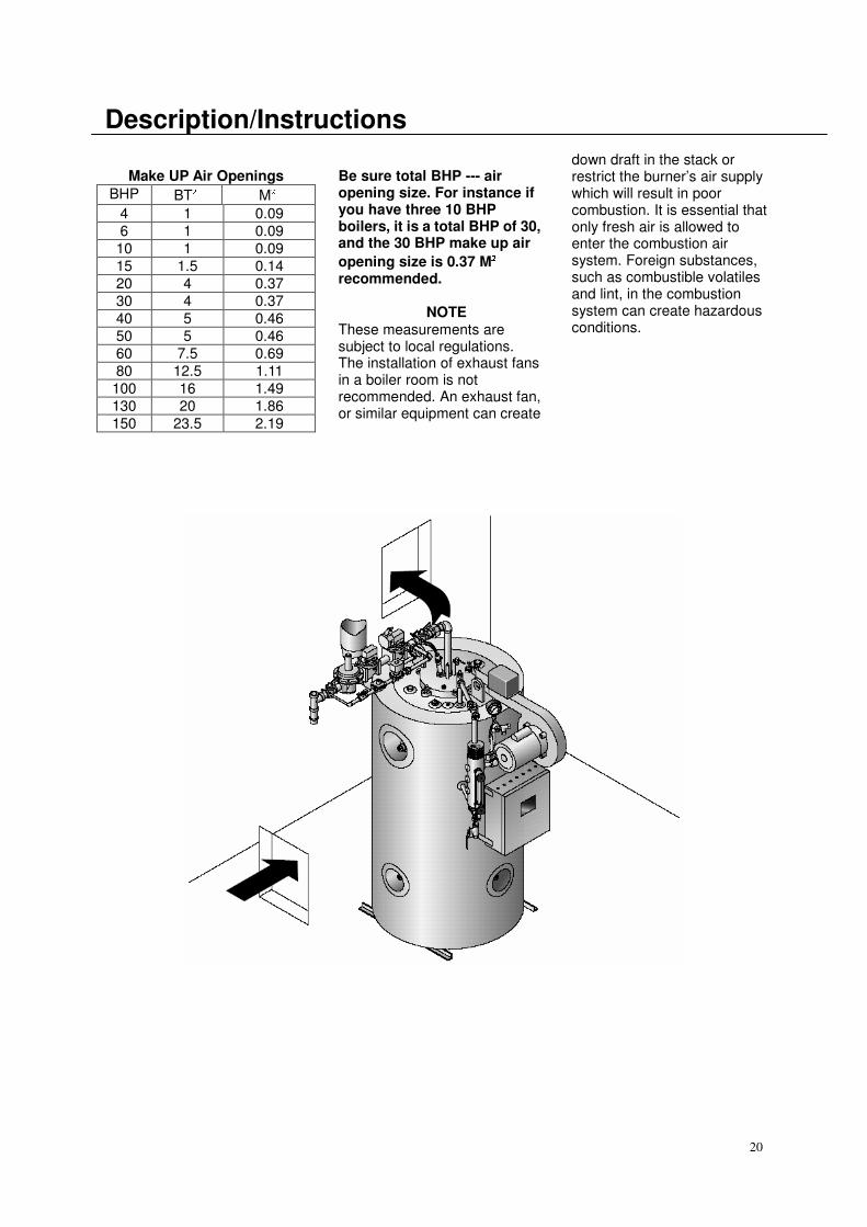
treated, heated, pumped, converted to steam, and condensed. This costs money and when condensate is returned to the boiler, money is saved. Electrical Requirements a) Connect wiring as shown in the wiring diagram which is furnished inside the electrical control panel box. b) Be sure to install a separate fused disconnect for each. The disconnect should be installed in compliance with all local codes. c) Connections for an optional audible alarm are provided in the control panel and are clearly indicated on the diagram. Fresh Air Supply for Boiler Room a) It is most important to provide free access of air to the boiler. 6.4cm2 is needed for every 756 Kcal). b) Proper ventilation of the boiler room is essential for good combustion. Install two fresh air openings, one at a low level of 610mm from floor and one at a higher level on the boiler room (See the picture). This will provide a flow of fresh air intake into from the bottom hole and exhaust the hot air from the top hole. c) The following openings are recommended for each size boiler:
20
Description/Instructions
Make UP Air Openings
BHP BT² M²
4 1 0.09
6 1 0.09
10 1 0.09
15 1.5 0.14
20 4 0.37
30 4 0.37
40 5 0.46
50 5 0.46
60 7.5 0.69
80 12.5 1.11
100 16 1.49
130 20 1.86
150 23.5 2.19
Be sure total BHP --- air opening size. For instance if you have three 10 BHP boilers, it is a total BHP of 30, and the 30 BHP make up air
opening size is 0.37 M²²²² recommended. NOTE These measurements are subject to local regulations. The installation of exhaust fans in a boiler room is not recommended. An exhaust fan, or similar equipment can create
down draft in the stack or restrict the burner’s air supply which will result in poor combustion. It is essential that only fresh air is allowed to enter the combustion air system. Foreign substances, such as combustible volatiles and lint, in the combustion system can create hazardous conditions.
Description/Instruction
21
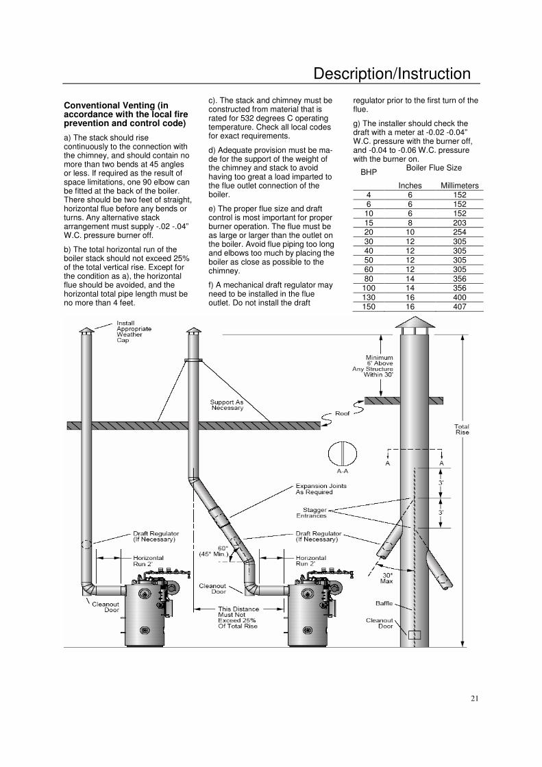
Conventional Venting (in accordance with the local fire prevention and control code)
a) The stack should rise continuously to the connection with the chimney, and should contain no more than two bends at 45 angles or less. If required as the result of space limitations, one 90 elbow can be fitted at the back of the boiler. There should be two feet of straight, horizontal flue before any bends or turns. Any alternative stack arrangement must supply -.02 -.04” W.C. pressure burner off.
b) The total horizontal run of the boiler stack should not exceed 25% of the total vertical rise. Except for the condition as a), the horizontal flue should be avoided, and the horizontal total pipe length must be no more than 4 feet.
c). The stack and chimney must be constructed from material that is rated for 532 degrees C operating temperature. Check all local codes for exact requirements.
d) Adequate provision must be ma- de for the support of the weight of the chimney and stack to avoid having too great a load imparted to the flue outlet connection of the boiler.
e) The proper flue size and draft control is most important for proper burner operation. The flue must be as large or larger than the outlet on the boiler. Avoid flue piping too long and elbows too much by placing the boiler as close as possible to the chimney.
f) A mechanical draft regulator may need to be installed in the flue outlet. Do not install the draft
regulator prior to the first turn of the flue.
g) The installer should check the draft with a meter at -0.02 -0.04” W.C. pressure with the burner off, and -0.04 to -0.06 W.C. pressure with the burner on.
BHP Boiler Flue Size
Inches Millimeters
4 6 152 6 6 152 10 6 152 15 8 203 20 10 254 30 12 305 40 12 305 50 12 305 60 12 305 80 14 356
100 14 356 130 16 400 150 16 407
Description/Instruction
22
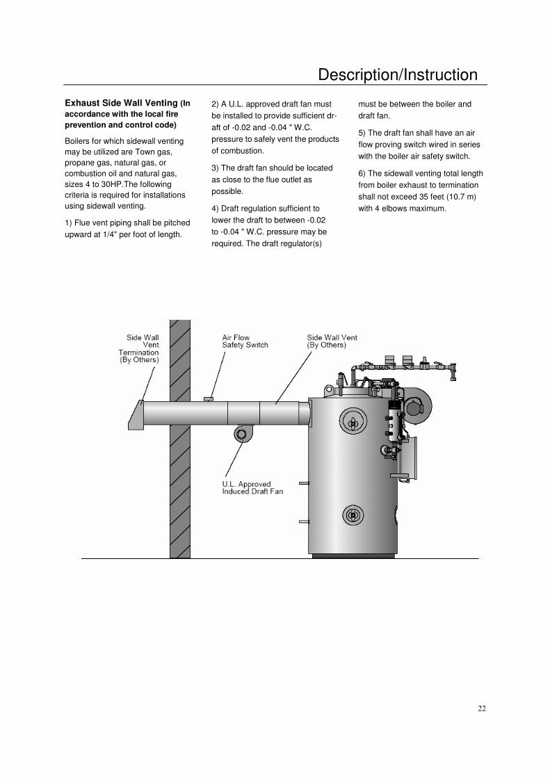
Exhaust Side Wall Venting (In
accordance with the local fire
prevention and control code)
Boilers for which sidewall venting
may be utilized are Town gas,
propane gas, natural gas, or
combustion oil and natural gas,
sizes 4 to 30HP.The following
criteria is required for installations
using sidewall venting.
1) Flue vent piping shall be pitched
upward at 1/4" per foot of length.
2) A U.L. approved draft fan must
be installed to provide sufficient dr-
aft of -0.02 and -0.04 " W.C.
pressure to safely vent the products
of combustion.
3) The draft fan should be located
as close to the flue outlet as
possible.
4) Draft regulation sufficient to
lower the draft to between -0.02
to -0.04 " W.C. pressure may be
required. The draft regulator(s)
must be between the boiler and
draft fan.
5) The draft fan shall have an air
flow proving switch wired in series
with the boiler air safety switch.
6) The sidewall venting total length
from boiler exhaust to termination
shall not exceed 35 feet (10.7 m)
with 4 elbows maximum.
Description/Instruction
23
Combustion Air Intake (In
accordance with the local fire
prevention and control code )
This shall be applicable only for gas fired vertical units, sizes 4-30 boiler horsepower. The following criteria are required for installations using combustion air intake assemblies. 1) Outside air intake inlet shall be equipped with a vent cap in order to prevent flame blow out from excessive wind. This vent cap shall have a minimum cross sectional opening equal to an 8 inch vent pipe. 2) All intake ducting shall have a cross sectional area equal to or greater than 50 square inches. 3) A mesh screen shall be affixed to the air inlet with openings of approximately 1/2" x 3/4". 4) The total length from outdoors to the boiler intake shall not exceed 35 feet (10.7 m) with four elbows maximum.
Corrosion of flue pipe
a) In the case of a combustion flue
pipe, acid may develop over a long
period of time per the following
process. Chlorine containing gases,
such as halocarbon refrigerants,
carbon tetrachloride,
trichloroethylene, when drawn into
combustion air are broken down
into elemental chlorine gas which
exits up the flue pipe. If the flue
pipe is cold, as it would be if the
combustion process had been off
for some time, the water vapor
condenses in the flue pipe during
the first few minutes of ignition and
the chlorine in the combustion gas
dissolves in the water forming
hydrochloric acid. As the
combustion system flue line
increases in temperature, the water
vapor no longer condenses
because the flue temperature is
above the dew point of the
combustion gas. The combustion
gas then dries out (dehydrates) the
hydrochloric acid solution leaving
behind dry chloride salt.
b) When the next cold start-up
occurs, the process repeats except
that more and more chloride
collects and concentrates along the
flue. As the quantity of chloride
increases it does not dehydrate
completely as the flue heats up and
a corrosive poultice develops which
attacks the steel and will also attack
the boiler.
c) Concentration levels of only a
few ppm of chlorine containing
compounds in combustion air can
produce serious corrosion over
long periods of time. High chlorine
containing compounds such as
carbon tetrachloride or perchloride
would be prime suspects.
Installation Check Points
1) Make sure all piping connections
are complete and tight.
2) Make sure the pressure controls
are adjusted properly.
3) Make sure all electrical
connections in the control panel
box, the water column, and
elsewhere are secure.
4) Make sure the door in the boiler
room is closed. Combustion air
contaminates can cause damage to
the boiler jacket and stack.
NOTE
After installation is complete and
prior to operation the pressure
vessel should be cleaned.
Cleaning the Pressure Vessel
a) After the boiler has been
installed and before it is placed in
service it is advisable to purge the
pressure vessel of any oil film, dirt,
or other impurities. Clean the
pressure vessel as follows:
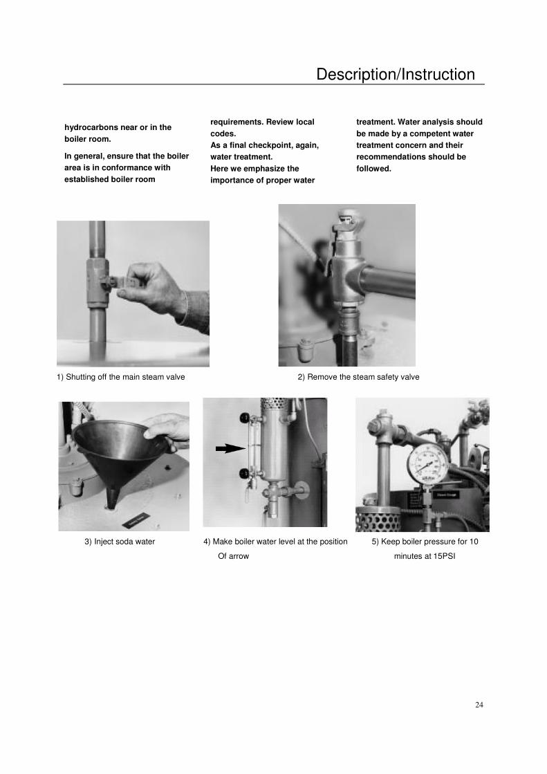
1) Isolate the boiler from the system
by shutting off the main steam
valve.
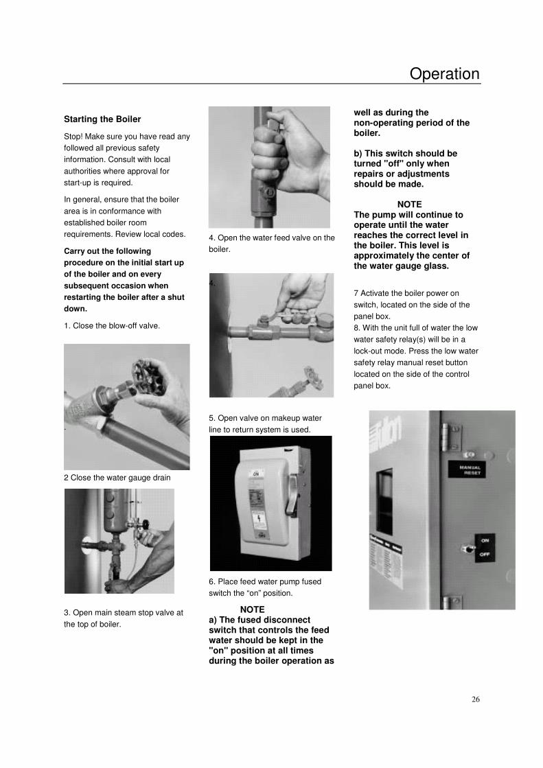
2) Remove the steam safety valve.
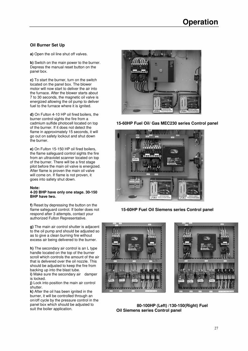
3) Mix washing soda with water r
and pour it in- to the boiler through
the steam safety valve opening.
4) The mixture of washing soda to
water is as follows:
5) Replace the steam safety valve.
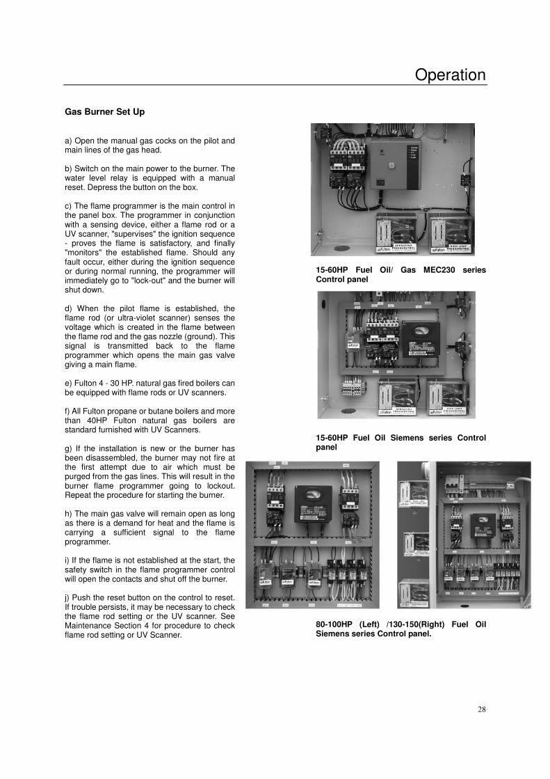
6) Fill the boiler with water. Water
column is about center in the water
gauge glass.
7) Generate 15 PSI (1.054kg/cm2)
of steam and shut off the boiler.
Allow this hot solution to remain in
the boiler for 10 minutes.
8) Drain and flush the boiler twice
with fresh water.
9) To remove all the oil and dirt
from the main steam and the
condensate return lines, allow the
returns to go into a floor drain or a
safe discharge point for the first
week of operation.
CAUTION
Do not store halogenated
Boiler Size Soda
4-6 454g
10-15 908g 20-30 1362g
40-50 1589g
60 1816g
80 2270g
100-130 3178g
150 4250g
Description/Instruction
24
hydrocarbons near or in the
boiler room.
In general, ensure that the boiler
area is in conformance with
established boiler room
requirements. Review local
codes.
As a final checkpoint, again,
water treatment.
Here we emphasize the
importance of proper water
treatment. Water analysis should
be made by a competent water
treatment concern and their
recommendations should be
followed.
1) Shutting off the main steam valve 2) Remove the steam safety valve
3) Inject soda water 4) Make boiler water level at the position 5) Keep boiler pressure for 10
Of arrow minutes at 15PSI

Operation
25
Operation
26
Starting the Boiler
Stop! Make sure you have read any
followed all previous safety
information. Consult with local
authorities where approval for
start-up is required.
In general, ensure that the boiler
area is in conformance with
established boiler room
requirements. Review local codes.
Carry out the following
procedure on the initial start up
of the boiler and on every
subsequent occasion when
restarting the boiler after a shut
down.
1. Close the blow-off valve.
.
2 Close the water gauge drain
3. Open main steam stop valve at
the top of boiler.
4. Open the water feed valve on the
boiler.
4.
5. Open valve on makeup water
line to return system is used.
5.
6.
6. Place feed water pump fused
switch the “on” position.
NOTE
a) The fused disconnect switch that controls the feed water should be kept in the "on" position at all times during the boiler operation as
well as during the non-operating period of the boiler. b) This switch should be turned "off" only when repairs or adjustments should be made.
NOTE The pump will continue to operate until the water reaches the correct level in the boiler. This level is approximately the center of the water gauge glass.
7 Activate the boiler power on
switch, located on the side of the
panel box.
8. With the unit full of water the low
water safety relay(s) will be in a
lock-out mode. Press the low water
safety relay manual reset button
located on the side of the control
panel box.
Operation
27
Oil Burner Set Up a) Open the oil line shut off valves. b) Switch on the main power to the burner. Depress the manual reset button on the panel box. c) To start the burner, turn on the switch located on the panel box. The blower motor will now start to deliver the air into the furnace. After the blower starts about 7 to 30 seconds, the magnetic oil valve is energized allowing the oil pump to deliver fuel to the furnace where it is ignited. d) On Fulton 4-10 HP oil fired boilers, the burner control sights the fire from a cadmium sulfide photocell located on top of the burner. If it does not detect the flame in approximately 15 seconds, it will go out on safety lockout and shut down the burner. e) On Fulton 15-150 HP oil fired boilers, the flame safeguard control sights the fire from an ultraviolet scanner located on top of the burner. There will be a first stage pilot before the main oil valve is energized. After flame is proven the main oil valve will come on. If flame is not proven, it goes into safety shut down. Note: 4-20 BHP have only one stage. 30-150 BHP have two. f) Reset by depressing the button on the flame safeguard control. If boiler does not respond after 3 attempts, contact your authorized Fulton Representative. g) The main air control shutter is adjacent to the oil pump and should be adjusted so as to give a clean burning fire without excess air being delivered to the burner. h) The secondary air control is an L type handle located on the top of the burner scroll which controls the amount of the air that is delivered over the oil nozzle. This should be adjusted to keep the fire from backing up into the blast tube. i) Make sure the secondary air damper is locked. j) Lock into position the main air control shutter. k) After the oil has been ignited in the burner, it will be controlled through an on/off cycle by the pressure control in the panel box which should be adjusted to suit the boiler application.
15-60HP Fuel Oil/ Gas MEC230 series Control panel
15-60HP Fuel Oil Siemens series Control panel
80-100HP (Left) /130-150(Right) Fuel
Oil Siemens series Control panel
Operation
28
Gas Burner Set Up a) Open the manual gas cocks on the pilot and main lines of the gas head. b) Switch on the main power to the burner. The water level relay is equipped with a manual reset. Depress the button on the box. c) The flame programmer is the main control in the panel box. The programmer in conjunction with a sensing device, either a flame rod or a UV scanner, "supervises" the ignition sequence - proves the flame is satisfactory, and finally "monitors" the established flame. Should any fault occur, either during the ignition sequence or during normal running, the programmer will immediately go to "lock-out" and the burner will shut down. d) When the pilot flame is established, the flame rod (or ultra-violet scanner) senses the voltage which is created in the flame between the flame rod and the gas nozzle (ground). This signal is transmitted back to the flame programmer which opens the main gas valve giving a main flame. e) Fulton 4 - 30 HP. natural gas fired boilers can be equipped with flame rods or UV scanners. f) All Fulton propane or butane boilers and more than 40HP Fulton natural gas boilers are standard furnished with UV Scanners. g) If the installation is new or the burner has been disassembled, the burner may not fire at the first attempt due to air which must be purged from the gas lines. This will result in the burner flame programmer going to lockout. Repeat the procedure for starting the burner. h) The main gas valve will remain open as long as there is a demand for heat and the flame is carrying a sufficient signal to the flame programmer. i) If the flame is not established at the start, the safety switch in the flame programmer control will open the contacts and shut off the burner. j) Push the reset button on the control to reset. If trouble persists, it may be necessary to check the flame rod setting or the UV scanner. See Maintenance Section 4 for procedure to check flame rod setting or UV Scanner.
15-60HP Fuel Oil/ Gas MEC230 series Control panel 15-60HP Fuel Oil Siemens series Control panel 80-100HP (Left) /130-150(Right) Fuel Oil Siemens series Control panel.
Operation
29
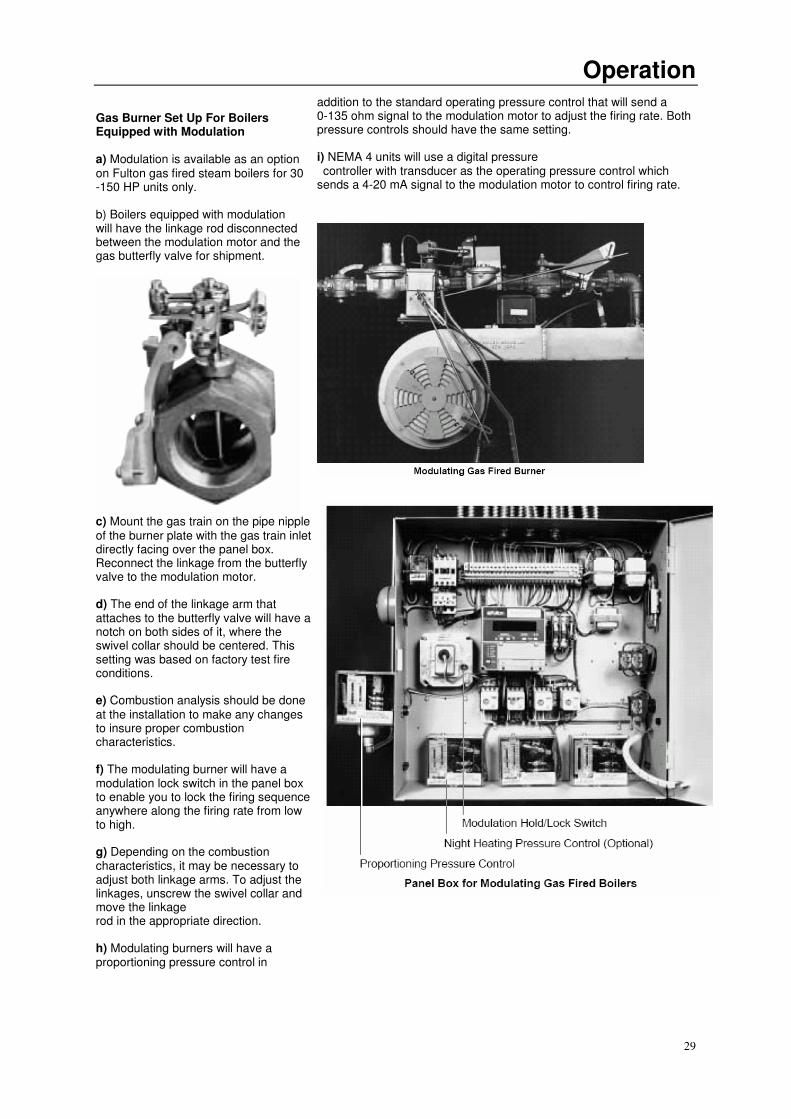
Gas Burner Set Up For Boilers Equipped with Modulation a) Modulation is available as an option on Fulton gas fired steam boilers for 30 -150 HP units only. b) Boilers equipped with modulation will have the linkage rod disconnected between the modulation motor and the gas butterfly valve for shipment.
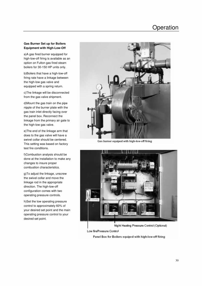
c) Mount the gas train on the pipe nipple of the burner plate with the gas train inlet directly facing over the panel box. Reconnect the linkage from the butterfly valve to the modulation motor. d) The end of the linkage arm that attaches to the butterfly valve will have a notch on both sides of it, where the swivel collar should be centered. This setting was based on factory test fire conditions. e) Combustion analysis should be done at the installation to make any changes to insure proper combustion characteristics. f) The modulating burner will have a modulation lock switch in the panel box to enable you to lock the firing sequence anywhere along the firing rate from low to high. g) Depending on the combustion characteristics, it may be necessary to adjust both linkage arms. To adjust the linkages, unscrew the swivel collar and move the linkage rod in the appropriate direction. h) Modulating burners will have a proportioning pressure control in
addition to the standard operating pressure control that will send a 0-135 ohm signal to the modulation motor to adjust the firing rate. Both pressure controls should have the same setting. i) NEMA 4 units will use a digital pressure controller with transducer as the operating pressure control which sends a 4-20 mA signal to the modulation motor to control firing rate.
Operation
30
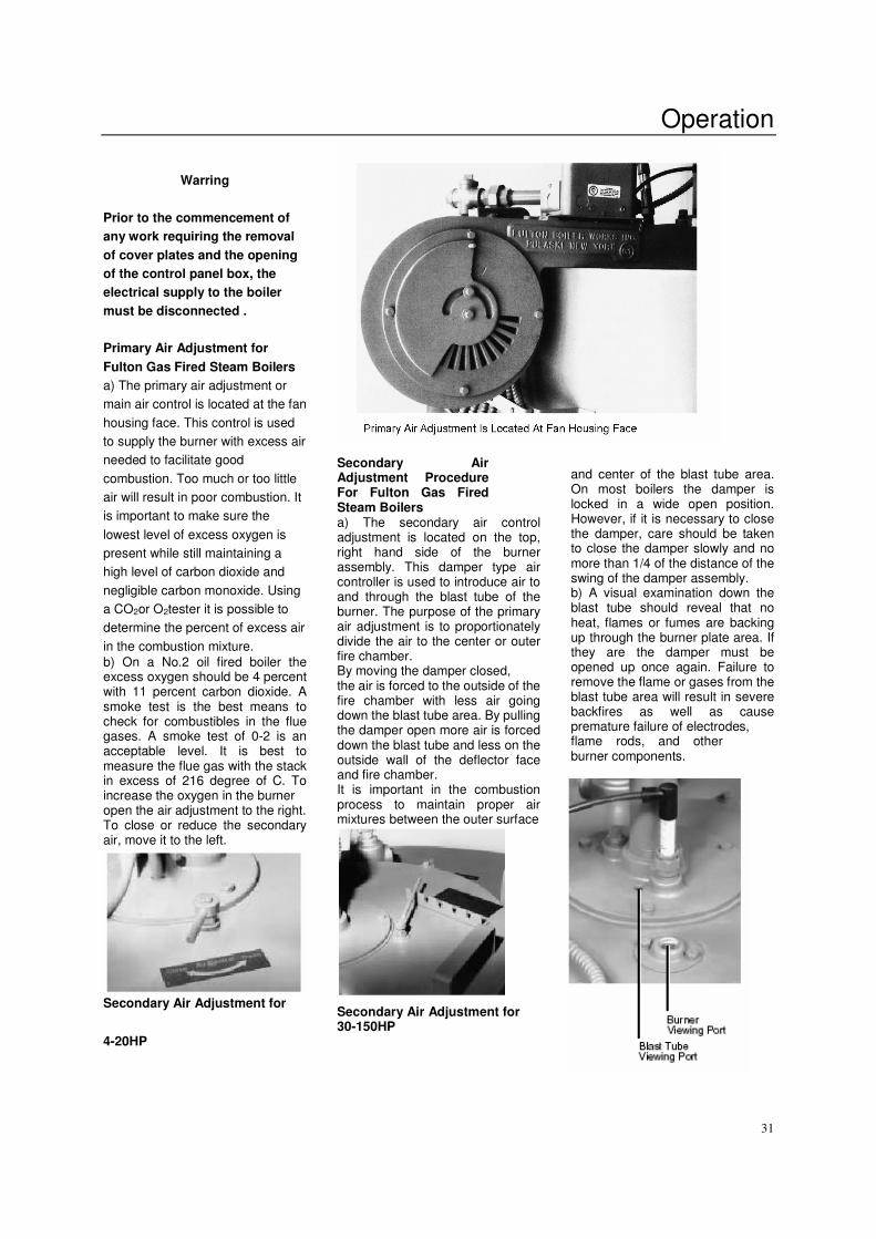
Gas Burner Set up for Boilers
Equipment with High-Low-Off
a)A gas fired burner equipped for
high-low-off firing is available as an
option on Fulton gas fired steam
boilers for 30-150 HP units only.
b)Boilers that have a high-low-off
firing rate have a linkage between
the high-low gas valve and
equipped with a spring return.
c)The linkage will be disconnected
from the gas valve shipment.
d)Mount the gas train on the pipe
nipple of the burner plate with the
gas train inlet directly facing over
the panel box. Reconnect the
linkage from the primary air gate to
the high-low gas valve.
e)The end of the linkage arm that
does to the gas valve will have a
swivel collar should be centered.
This setting was based on factory
test fire conditions.
f)Combustion analysis should be
done at the installation to make any
changes to insure proper
combustion characteristics.
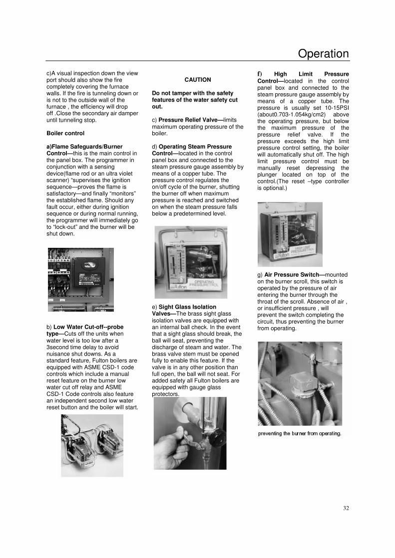
g)To adjust the linkage, unscrew
the swivel collar and move the
linkage rod in the appropriate
direction. The high-low-off
configuration comes with two
operating pressure controls.
h)Set the low operating pressure
control to approximately 60% of
your desired set point and the main
operating pressure control to your
desired set point.
Operation
31
Warring
Prior to the commencement of
any work requiring the removal
of cover plates and the opening
of the control panel box, the
electrical supply to the boiler
must be disconnected .
Primary Air Adjustment for
Fulton Gas Fired Steam Boilers
a) The primary air adjustment or
main air control is located at the fan
housing face. This control is used
to supply the burner with excess air
needed to facilitate good
combustion. Too much or too little
air will result in poor combustion. It
is important to make sure the
lowest level of excess oxygen is
present while still maintaining a
high level of carbon dioxide and
negligible carbon monoxide. Using
a CO2or O2tester it is possible to
determine the percent of excess air
in the combustion mixture.
b) On a No.2 oil fired boiler the excess oxygen should be 4 percent with 11 percent carbon dioxide. A smoke test is the best means to check for combustibles in the flue gases. A smoke test of 0-2 is an acceptable level. It is best to measure the flue gas with the stack in excess of 216 degree of C. To increase the oxygen in the burner open the air adjustment to the right. To close or reduce the secondary air, move it to the left.
Secondary Air Adjustment for
Secondary Air Adjustment Procedure For Fulton Gas Fired Steam Boilers a) The secondary air control adjustment is located on the top, right hand side of the burner assembly. This damper type air controller is used to introduce air to and through the blast tube of the burner. The purpose of the primary air adjustment is to proportionately divide the air to the center or outer fire chamber. By moving the damper closed, the air is forced to the outside of the fire chamber with less air going down the blast tube area. By pulling the damper open more air is forced down the blast tube and less on the outside wall of the deflector face and fire chamber. It is important in the combustion process to maintain proper air mixtures between the outer surface Secondary Air Adjustment for 30-150HP
and center of the blast tube area. On most boilers the damper is locked in a wide open position. However, if it is necessary to close the damper, care should be taken to close the damper slowly and no more than 1/4 of the distance of the swing of the damper assembly. b) A visual examination down the blast tube should reveal that no heat, flames or fumes are backing up through the burner plate area. If they are the damper must be opened up once again. Failure to remove the flame or gases from the blast tube area will result in severe backfires as well as cause premature failure of electrodes, flame rods, and other burner components.
4-20HP
Operation
32
c)A visual inspection down the view port should also show the fire completely covering the furnace walls. If the fire is tunneling down or is not to the outside wall of the furnace , the efficiency will drop off .Close the secondary air damper until tunneling stop. Boiler control a)Flame Safeguards/Burner Control—this is the main control in the panel box. The programmer in conjunction with a sensing device(flame rod or an ultra violet scanner) “supervises the ignition sequence—proves the flame is satisfactory—and finally “monitors” the established flame. Should any fault occur, either during ignition sequence or during normal running, the programmer will immediately go to “lock-out” and the burner will be shut down. b) Low Water Cut-off--probe type—Cuts off the units when water level is too low after a 3second time delay to avoid nuisance shut downs. As a standard feature, Fulton boilers are equipped with ASME CSD-1 code controls which include a manual reset feature on the burner low water cut off relay and ASME CSD-1 Code controls also feature an independent second low water reset button and the boiler will start.
CAUTION
Do not tamper with the safety features of the water safety cut out. c) Pressure Relief Valve—limits maximum operating pressure of the boiler. d) Operating Steam Pressure Control—located in the control panel box and connected to the steam pressure gauge assembly by means of a copper tube. The pressure control regulates the on/off cycle of the burner, shutting the burner off when maximum pressure is reached and switched on when the steam pressure falls below a predetermined level. e) Sight Glass Isolation Valves—The brass sight glass isolation valves are equipped with an internal ball check. In the event that a sight glass should break, the ball will seat, preventing the discharge of steam and water. The brass valve stem must be opened fully to enable this feature. If the valve is in any other position than full open, the ball will not seat. For added safety all Fulton boilers are equipped with gauge glass protectors.
f) High Limit Pressure Control—located in the control panel box and connected to the steam pressure gauge assembly by means of a copper tube. The pressure is usually set 10-15PSI (about0.703-1.054kg/cm2) above the operating pressure, but below the maximum pressure of the pressure relief valve. If the pressure exceeds the high limit pressure control setting, the boiler will automatically shut off. The high limit pressure control must be manually reset depressing the plunger located on top of the control.(The reset –type controller is optional.)
g) Air Pressure Switch—mounted on the burner scroll, this switch is operated by the pressure of air entering the burner through the throat of the scroll. Absence of air , or insufficient pressure , will prevent the switch completing the circuit, thus preventing the burner from operating.
Operation
33
CAUTION
When stopping the boiler for any extensive repairs, shut off main disconnect switches on both the boiler side as well as the feed
water side.
NOTE To ensure that your Fulton Steam Boiler is kept operating
safety and efficiently, follow the maintenance procedures set forth in section 4 of this manual.

Maintenance
34
Maintenance
35
Maintenance
36
NOTE To ensure the continued safety efficiency of the boiler, the schedule of maintenance outlined in this section should be adhered to.
WARRING Prior to the commencement of any work requiring the removal of cover plates and the opening of the control panel box, the electrical supply to the boiler must be disconnected.
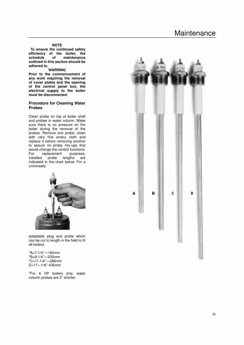
Procedure for Cleaning Water Probes Clean probe on top of boiler shell and probes in water column. Make sure there is no pressure on the boiler during the removal of the probes. Remove one probe, clean with very fine emery cloth and replace it before removing another to assure no probe mix-ups that would change the control functions. For replacement purposes, installed probe lengths are indicated in the chart below. For a universally adaptable plug and probe which can be cut to length in the field to fit all boilers. *A=7-1/4’’—184mm *B=9-1/4’’—235mm *C=11-1/4’’—286mm D=17—1/8’’-435mm *For 4 HP boilers only, water column probes are 2’’ shorter.
Maintenance
37
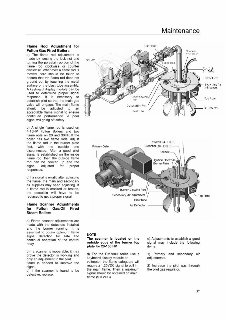
Flame Rod Adjustment for Fulton Gas Fired Boilers a) The flame rod adjustment is made by loosing the lock nut and turning the porcelain portion of the flame rod clockwise or counter clockwise. Whenever a flame rod is moved, care should be taken to ensure that the flame rod does not ground out by touching the metal surface of the blast tube assembly. A keyboard display module can be used to determine proper signal response. It is necessary to establish pilot so that the main gas valve will engage. The main flame should be adjusted to an acceptable flame signal to ensure continued performance. A poor signal will going off safety. b) A single flame rod is used on 4-15HP Fulton Boilers and two flame rods on 20 and 30HP. If the boiler has two flame rods, adjust the flame rod in the burner plate first, with the outside one disconnected. After a good pilot signal is established on the inside flame rod, then the outside flame rod can be hooked up and the signal adjusted for proper responses.
c)If a signal is erratic after adjusting the flame, the main and secondary air supplies may need adjusting. If a flame rod is cracked or broken, the porcelain will have to be replaced to get a proper signal.
Flame Scanner Adjustments for Fulton Gas/Oil Fired Steam Boilers a) Flame scanner adjustments are made with the detectors installed and the burner running. It is essential to obtain optimum flame signal detection for safe and continual operation of the control relay. b)If a scanner is inoperable, it may prove the detector is working and only an adjustment to the pilot flame is needed to improve the signal. c) If the scanner is found to be defective, replace.
NOTE The scanner is located on the outside edge of the burner top plate for 20-150 HP. d) For the RM7800 series use a keyboard display module or voltmeter, the flame safeguard will require a 1.25VDC signal to pull in the main flame. Then a maximum signal should be obtained on main flame.(5.0 VDC)
e) Adjustments to establish a good signal may include the following items: 1) Primary and secondary air adjustments. 2) Increase the pilot gas through the pilot gas regulator.
Maintenance
38
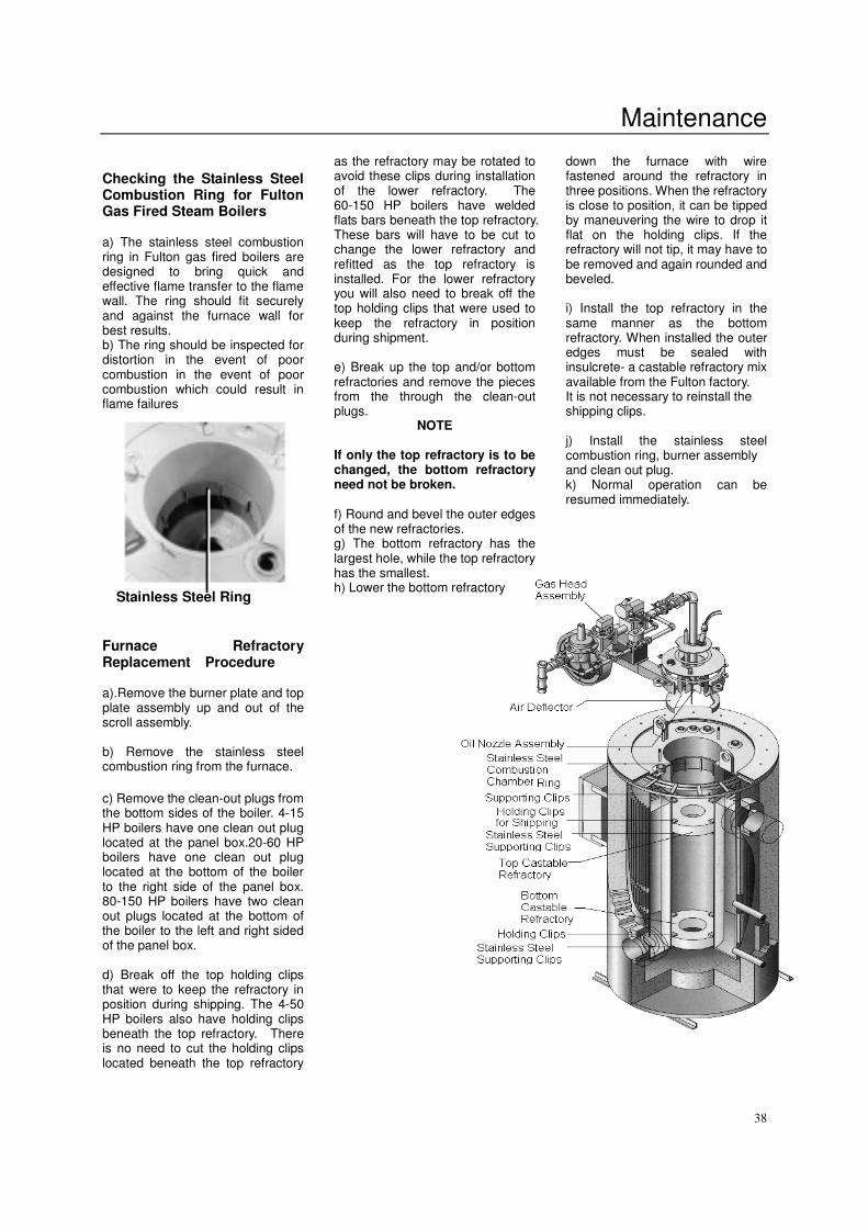
Checking the Stainless Steel Combustion Ring for Fulton Gas Fired Steam Boilers a) The stainless steel combustion ring in Fulton gas fired boilers are designed to bring quick and effective flame transfer to the flame wall. The ring should fit securely and against the furnace wall for best results. b) The ring should be inspected for distortion in the event of poor combustion in the event of poor combustion which could result in flame failures
Stainless Steel Ring
Furnace Refractory Replacement Procedure
a).Remove the burner plate and top plate assembly up and out of the scroll assembly. b) Remove the stainless steel combustion ring from the furnace.
c) Remove the clean-out plugs from the bottom sides of the boiler. 4-15 HP boilers have one clean out plug located at the panel box.20-60 HP boilers have one clean out plug located at the bottom of the boiler to the right side of the panel box. 80-150 HP boilers have two clean out plugs located at the bottom of the boiler to the left and right sided of the panel box. d) Break off the top holding clips that were to keep the refractory in position during shipping. The 4-50 HP boilers also have holding clips beneath the top refractory. There is no need to cut the holding clips located beneath the top refractory
as the refractory may be rotated to avoid these clips during installation of the lower refractory. The 60-150 HP boilers have welded flats bars beneath the top refractory. These bars will have to be cut to change the lower refractory and refitted as the top refractory is installed. For the lower refractory you will also need to break off the top holding clips that were used to keep the refractory in position during shipment. e) Break up the top and/or bottom refractories and remove the pieces from the through the clean-out plugs.
NOTE If only the top refractory is to be changed, the bottom refractory need not be broken. f) Round and bevel the outer edges of the new refractories. g) The bottom refractory has the largest hole, while the top refractory has the smallest. h) Lower the bottom refractory
down the furnace with wire fastened around the refractory in three positions. When the refractory is close to position, it can be tipped by maneuvering the wire to drop it flat on the holding clips. If the refractory will not tip, it may have to be removed and again rounded and beveled. i) Install the top refractory in the same manner as the bottom refractory. When installed the outer edges must be sealed with insulcrete- a castable refractory mix available from the Fulton factory. It is not necessary to reinstall the shipping clips. j) Install the stainless steel combustion ring, burner assembly and clean out plug. k) Normal operation can be resumed immediately.
Maintenance
39
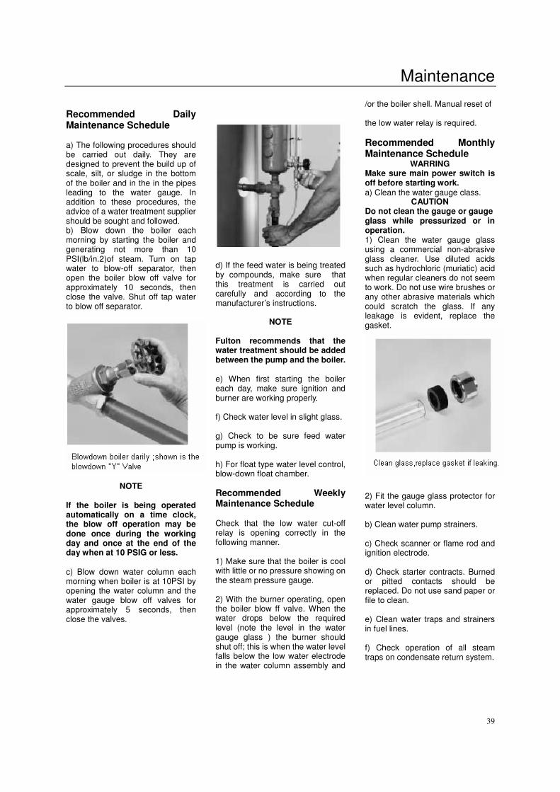
Recommended Daily Maintenance Schedule a) The following procedures should be carried out daily. They are designed to prevent the build up of scale, silt, or sludge in the bottom of the boiler and in the in the pipes leading to the water gauge. In addition to these procedures, the advice of a water treatment supplier should be sought and followed. b) Blow down the boiler each morning by starting the boiler and generating not more than 10 PSI(lb/in.2)of steam. Turn on tap water to blow-off separator, then open the boiler blow off valve for approximately 10 seconds, then close the valve. Shut off tap water to blow off separator.
NOTE
If the boiler is being operated automatically on a time clock, the blow off operation may be done once during the working day and once at the end of the day when at 10 PSIG or less. c) Blow down water column each morning when boiler is at 10PSI by opening the water column and the water gauge blow off valves for approximately 5 seconds, then close the valves.
d) If the feed water is being treated by compounds, make sure that this treatment is carried out carefully and according to the manufacturer’s instructions.
NOTE Fulton recommends that the water treatment should be added between the pump and the boiler. e) When first starting the boiler each day, make sure ignition and burner are working properly. f) Check water level in slight glass. g) Check to be sure feed water pump is working. h) For float type water level control, blow-down float chamber.
Recommended Weekly Maintenance Schedule Check that the low water cut-off relay is opening correctly in the following manner. 1) Make sure that the boiler is cool with little or no pressure showing on the steam pressure gauge. 2) With the burner operating, open the boiler blow ff valve. When the water drops below the required level (note the level in the water gauge glass ) the burner should shut off; this is when the water level falls below the low water electrode in the water column assembly and
/or the boiler shell. Manual reset of the low water relay is required.
Recommended Monthly Maintenance Schedule
WARRING Make sure main power switch is off before starting work. a) Clean the water gauge class.
CAUTION Do not clean the gauge or gauge glass while pressurized or in operation. 1) Clean the water gauge glass using a commercial non-abrasive glass cleaner. Use diluted acids such as hydrochloric (muriatic) acid when regular cleaners do not seem to work. Do not use wire brushes or any other abrasive materials which could scratch the glass. If any leakage is evident, replace the gasket. 2) Fit the gauge glass protector for water level column. b) Clean water pump strainers. c) Check scanner or flame rod and ignition electrode. d) Check starter contracts. Burned or pitted contacts should be replaced. Do not use sand paper or file to clean. e) Clean water traps and strainers in fuel lines. f) Check operation of all steam traps on condensate return system.
Maintenance
40
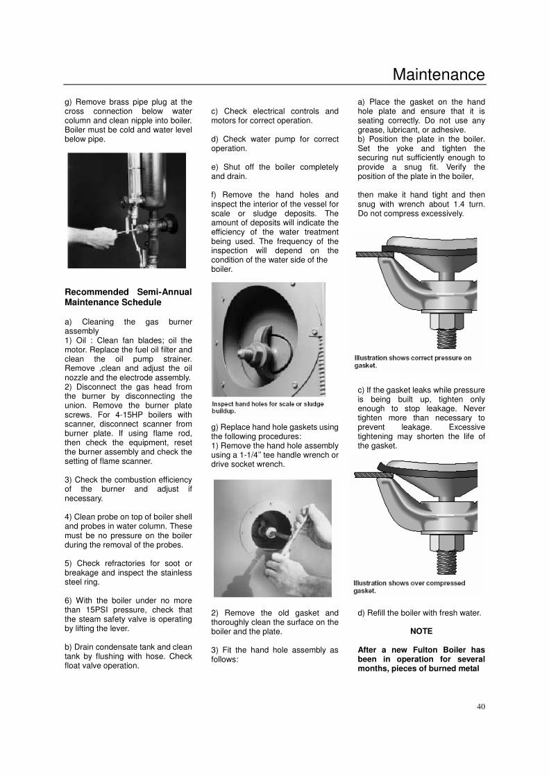
g) Remove brass pipe plug at the cross connection below water column and clean nipple into boiler. Boiler must be cold and water level below pipe. Recommended Semi-Annual Maintenance Schedule a) Cleaning the gas burner assembly 1) Oil : Clean fan blades; oil the motor. Replace the fuel oil filter and clean the oil pump strainer. Remove ,clean and adjust the oil nozzle and the electrode assembly. 2) Disconnect the gas head from the burner by disconnecting the union. Remove the burner plate screws. For 4-15HP boilers with scanner, disconnect scanner from burner plate. If using flame rod, then check the equipment, reset the burner assembly and check the setting of flame scanner. 3) Check the combustion efficiency of the burner and adjust if necessary. 4) Clean probe on top of boiler shell and probes in water column. These must be no pressure on the boiler during the removal of the probes. 5) Check refractories for soot or breakage and inspect the stainless steel ring. 6) With the boiler under no more than 15PSI pressure, check that the steam safety valve is operating by lifting the lever. b) Drain condensate tank and clean tank by flushing with hose. Check float valve operation.
c) Check electrical controls and motors for correct operation. d) Check water pump for correct operation. e) Shut off the boiler completely and drain. f) Remove the hand holes and inspect the interior of the vessel for scale or sludge deposits. The amount of deposits will indicate the efficiency of the water treatment being used. The frequency of the inspection will depend on the condition of the water side of the boiler. g) Replace hand hole gaskets using the following procedures: 1) Remove the hand hole assembly using a 1-1/4’’ tee handle wrench or drive socket wrench. 2) Remove the old gasket and thoroughly clean the surface on the boiler and the plate. 3) Fit the hand hole assembly as follows:
a) Place the gasket on the hand hole plate and ensure that it is seating correctly. Do not use any grease, lubricant, or adhesive. b) Position the plate in the boiler. Set the yoke and tighten the securing nut sufficiently enough to provide a snug fit. Verify the position of the plate in the boiler, then make it hand tight and then snug with wrench about 1.4 turn. Do not compress excessively. c) If the gasket leaks while pressure is being built up, tighten only enough to stop leakage. Never tighten more than necessary to prevent leakage. Excessive tightening may shorten the life of the gasket. d) Refill the boiler with fresh water.
NOTE After a new Fulton Boiler has been in operation for several months, pieces of burned metal
Maintenance
41
will be found in the space at the bottom of the boiler. These pieces of metal are the remains of a light gauge metal form which was used during manufacture for forming the boiler insulation. This is a normal condition and does not affect the efficiency or the life of the boiler in any way.
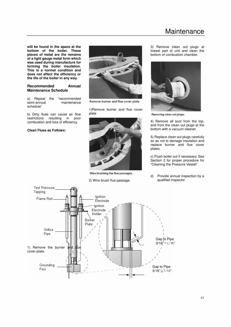
Recommended Annual Maintenance Schedule a) Repeat the “recommended semi-annual maintenance schedule” b) Dirty flues can cause air flow restrictions resulting in poor combustion and loss of efficiency. Clean Flues as Follows:
1) Remove the burner and flue cover plate.
1)Remove burner and flue cover plate 2) Wire brush flue passage.
3) Remove clean out plugs at lowest part of unit and clean the bottom of combustion chamber. 4) Remove all soot from the top, and from the clean out plugs at the bottom with a vacuum cleaner. 5) Replace clean out plugs carefully so as not to damage insulation and replace burner and flue cover plates. c) Flush boiler out if necessary. See Section 2 for proper procedure for “Cleaning the Pressure Vessel”. d) Provide annual inspection by a
qualified inspector.
Gap to Pipe
3/16”±1/16”
Gap to Pipe
3/16”±1/16”
Maintenance
42
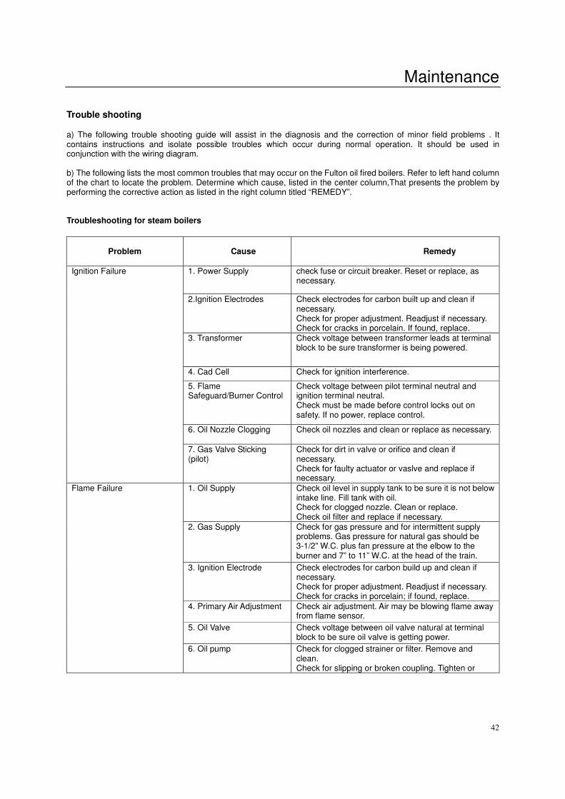
Trouble shooting a) The following trouble shooting guide will assist in the diagnosis and the correction of minor field problems . It contains instructions and isolate possible troubles which occur during normal operation. It should be used in conjunction with the wiring diagram. b) The following lists the most common troubles that may occur on the Fulton oil fired boilers. Refer to left hand column of the chart to locate the problem. Determine which cause, listed in the center column,That presents the problem by performing the corrective action as listed in the right column titled “REMEDY”. Troubleshooting for steam boilers
Problem
Cause
Remedy
1. Power Supply
check fuse or circuit breaker. Reset or replace, as necessary.
2.Ignition Electrodes
Check electrodes for carbon built up and clean if necessary. Check for proper adjustment. Readjust if necessary. Check for cracks in porcelain. If found, replace.
3. Transformer
Check voltage between transformer leads at terminal block to be sure transformer is being powered.
4. Cad Cell Check for ignition interference.
5. Flame Safeguard/Burner Control
Check voltage between pilot terminal neutral and ignition terminal neutral. Check must be made before control locks out on safety. If no power, replace control.
6. Oil Nozzle Clogging Check oil nozzles and clean or replace as necessary.
Ignition Failure
7. Gas Valve Sticking (pilot)
Check for dirt in valve or orifice and clean if necessary. Check for faulty actuator or vaslve and replace if necessary.
1. Oil Supply Check oil level in supply tank to be sure it is not below intake line. Fill tank with oil. Check for clogged nozzle. Clean or replace. Check oil filter and replace if necessary.
2. Gas Supply Check for gas pressure and for intermittent supply problems. Gas pressure for natural gas should be 3-1/2” W.C. plus fan pressure at the elbow to the burner and 7” to 11” W.C. at the head of the train.
3. Ignition Electrode
Check electrodes for carbon build up and clean if necessary. Check for proper adjustment. Readjust if necessary. Check for cracks in porcelain; if found, replace.
4. Primary Air Adjustment Check air adjustment. Air may be blowing flame away from flame sensor.
5. Oil Valve Check voltage between oil valve natural at terminal block to be sure oil valve is getting power.
Flame Failure
6. Oil pump Check for clogged strainer or filter. Remove and clean. Check for slipping or broken coupling. Tighten or
Maintenance
43
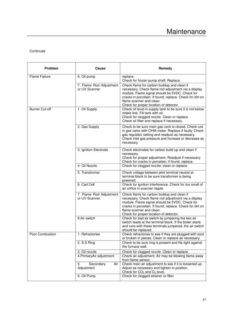
Continued
Problem
Cause
Remedy
6. Oil pump replace. Check for frozen pump shaft. Replace.
Flame Failure
7. Flame Rod Adjustment or UV Scanner
Check flame for carbon buildup and clean if necessary. Check flame rod adjustment via a display module. Flame signal should be 5VDC. Check for cracks in porcelain. If found, replace. Check for dirt on flame scanner and clean. Check for proper location of detector.
1. Oil Supply Check oil level in supply tank to be sure it is not below intake line. Fill tank with oil. Check for clogged nozzle. Clean or replace. Check oil filter and replace if necessary.
2. Gas Supply Check to be sure main gas cock is closed. Check coil in gas valve with OHM meter. Replace if faulty. Check gas regulator setting and readjust as necessary. Check inlet gas pressure and increase or decrease as necessary.
3. Ignition Electrode
Check electrodes for carbon build up and clean if necessary. Check for proper adjustment. Readjust if necessary. Check for cracks in porcelain; if found, replace.
4. Oil Nozzle Check for clogged nozzle; clean or replace.
5. Transformer Check voltage between pilot terminal neutral at terminal block to be sure transformer is being powered.
6. Cad Cell Check for ignition interference. Check for too small of an orifice in scanner nipple.
7. Flame Rod Adjustment or UV Scanner
Check flame for carbon buildup and clean if necessary. Check flame rod adjustment via a display module. Flame signal should be 5VDC. Check for cracks in porcelain. If found, replace. Check for dirt on flame scanner and clean. Check for proper location of detector.
Burner Cut-off
8.Air switch Check for bad air switch by jumpering the two air switch leads at the terminal block. If the boiler starts and runs with these terminals jumpered, the air switch should be replaced.
1. Refractories Check refractories to see if they are plugged with soot or broken in pieces. Clean or replace as necessary.
2. S.S Ring Check to be sure ring is present and fits tight against the furnace wall.
3. Oil nozzle Check for clogged nozzle. Clean or replace.
4.PrimaryAir adjustment Check air adjustment. Air may be blowing flame away from flame sensor.
5. Secondary Air Adjustment
Check main air adjustment to see if it is loosened up. Adjust as necessary and tighten in position. Check for CO2 and O2 level.
Poor Combustion 6. Oil Pump Check for clogged strainer or filter.
Maintenance
44
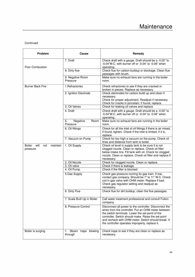
Continued
Problem
Cause
Remedy
7. Draft Check draft with a gauge. Draft should be a -0.02” to
-0.04”W.C. with burner off or -0.04” to -0.06” when operating.
8. Dirty flue Check flue for carbon buildup or blockage. Clean flue passages with brush.
Poor Combustion
9. Negative Room Pressure
Make sure no exhaust fans are running in the boiler room.
1.Refractories Check refractories to see if they are cracked or broken in pieces. Replace as necessary.
2. Ignition Electrode
Check electrodes for carbon build up and clean if necessary. Check for proper adjustment. Readjust if necessary. Check for cracks in porcelain; if found, replace.
3. Oil Valves Check for leaking oil valves and replace.
4. Draft Check draft with a gauge. Draft should be a -0.02” to -0.04”W.C. with burner off or -0.04” to -0.06” when operating.
5. Negative Room Pressure
Make sure no exhaust fans are running in the boiler room.
6. Oil fittings Check for all the inlet of oil fittings if there is air mixed, if found, tighten. Check if the inlet is limited, if it is, replace.
Burner Back Fire
7. Vacuum on Pump Check for too high a vacuum on the pump. Check oil lines and distance from tank to boiler.
1. Oil Supply Check oil level in supply tank to be sure it is not clogged nozzle. Clean or replace. Check oil filter below intake line. Fill tank with oil. Check for clogged nozzle. Clean or replace. Check oil filter and replace if necessary.
2. Oil Nozzle Check for clogged nozzle. Clean or replace.
3. Oil valve Check if there is leakage.
4. Oil Pump Check if the filter is blocked.
5.Gas Supply Check gas pressure coming ito gas train. If low, contact gas company. Should be 7” to 11” W.C. Check coil in gas valve with OHM meter. Replace if bad. Check gas regulator setting and readjust as necessary.
6. Dirty Flue Check flue for dirt buildup, clean the flue passages.
7. Scale Built Up in Boiler Call water treatment professional and consult Fulton company.
Boiler will not maintain pressure
8. Pressure Control Disconnect all power to the controller. Disconnect the wires from the controller. Put an OHM meter between the switch terminals. Lower the set point of the controller. Switch should make. Raise the set point and recheck with OHM meter. Switch should break. If the controller operates improperly, replace it.
Boiler is surging
1. Steam traps blowing through
Check traps to see if they are clean or replace as necessary.
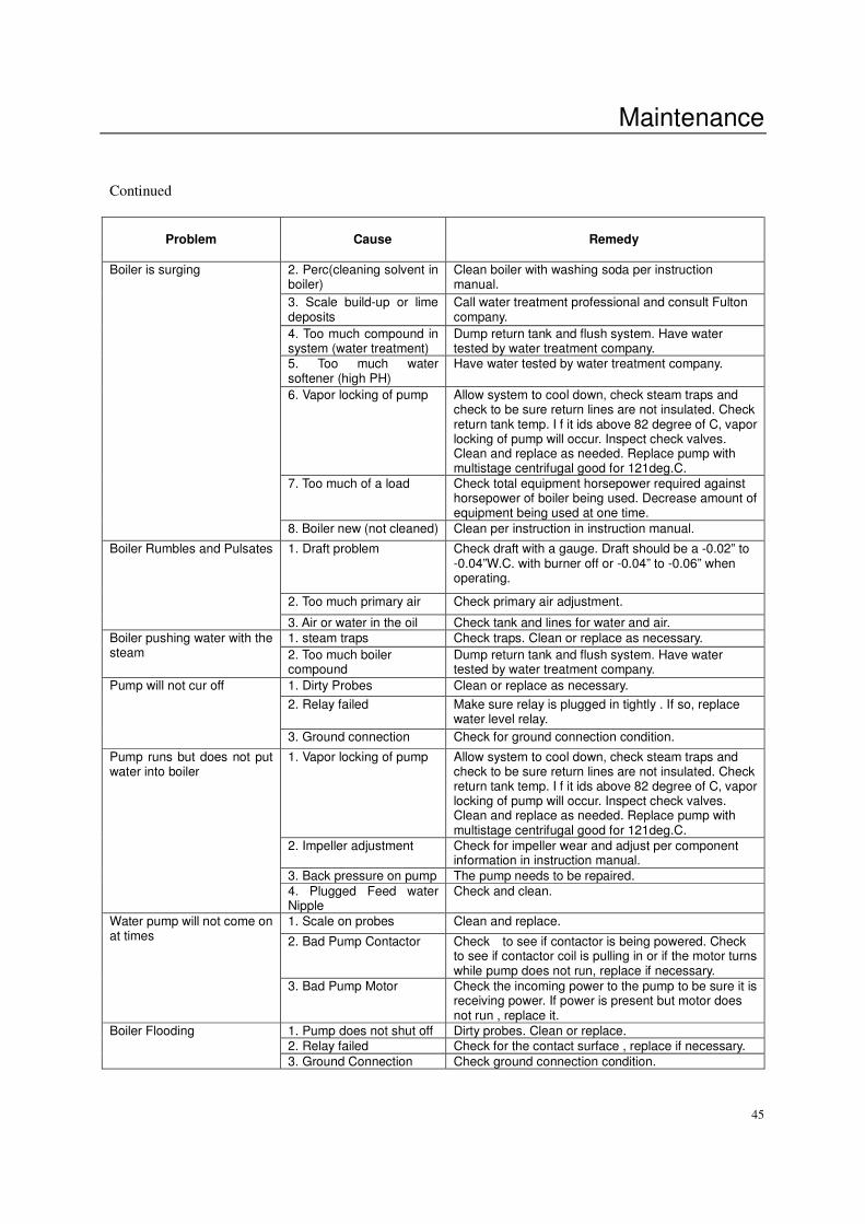
Maintenance
45
Continued
Problem
Cause
Remedy
2. Perc(cleaning solvent in boiler)
Clean boiler with washing soda per instruction manual.
3. Scale build-up or lime deposits
Call water treatment professional and consult Fulton company.
4. Too much compound in system (water treatment)
Dump return tank and flush system. Have water tested by water treatment company.
5. Too much water softener (high PH)
Have water tested by water treatment company.
6. Vapor locking of pump Allow system to cool down, check steam traps and check to be sure return lines are not insulated. Check return tank temp. I f it ids above 82 degree of C, vapor locking of pump will occur. Inspect check valves. Clean and replace as needed. Replace pump with multistage centrifugal good for 121deg.C.
7. Too much of a load
Check total equipment horsepower required against horsepower of boiler being used. Decrease amount of equipment being used at one time.
Boiler is surging 8. Boiler new (not cleaned) Clean per instruction in instruction manual.
1. Draft problem
Check draft with a gauge. Draft should be a -0.02” to -0.04”W.C. with burner off or -0.04” to -0.06” when operating.
2. Too much primary air Check primary air adjustment.
Boiler Rumbles and Pulsates
3. Air or water in the oil Check tank and lines for water and air.
1. steam traps Check traps. Clean or replace as necessary. Boiler pushing water with the steam 2. Too much boiler
compound Dump return tank and flush system. Have water tested by water treatment company.
1. Dirty Probes Clean or replace as necessary.
2. Relay failed Make sure relay is plugged in tightly . If so, replace water level relay.
Pump will not cur off
3. Ground connection Check for ground connection condition.
1. Vapor locking of pump Allow system to cool down, check steam traps and check to be sure return lines are not insulated. Check return tank temp. I f it ids above 82 degree of C, vapor locking of pump will occur. Inspect check valves. Clean and replace as needed. Replace pump with multistage centrifugal good for 121deg.C.
2. Impeller adjustment Check for impeller wear and adjust per component information in instruction manual.
3. Back pressure on pump The pump needs to be repaired.
Pump runs but does not put water into boiler
4. Plugged Feed water Nipple
Check and clean.
1. Scale on probes Clean and replace.
2. Bad Pump Contactor Check to see if contactor is being powered. Check to see if contactor coil is pulling in or if the motor turns while pump does not run, replace if necessary.
Water pump will not come on at times
3. Bad Pump Motor Check the incoming power to the pump to be sure it is receiving power. If power is present but motor does not run , replace it.
1. Pump does not shut off Dirty probes. Clean or replace. 2. Relay failed Check for the contact surface , replace if necessary.
Boiler Flooding 3. Ground Connection Check ground connection condition.
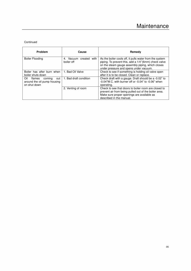
Maintenance
46
Continued
Problem
Cause
Remedy
Boiler Flooding
4. Vacuum created with boiler off
As the boiler cools off, it pulls water from the system piping. To prevent this, add a 1/4’’(6mm) check valve on the steam gauge assembly piping, which closes under pressure and opens under vacuum.
Boiler has after burn when boiler shuts down
1. Bad Oil Valve Check to see if something is holding oil valve open after it is to be closed. Clean or replace.
1. Bad draft condition Check draft with a gauge. Draft should be a -0.02” to -0.04”W.C. with burner off or -0.04” to -0.06” when operating.
Oil flames coming out around the oil pump housing on shut down
2. Venting of room Check to see that doors to boiler room are closed to prevent air from being pulled out of the boiler area. Make sure proper openings are available as described in the manual.

Parts
47
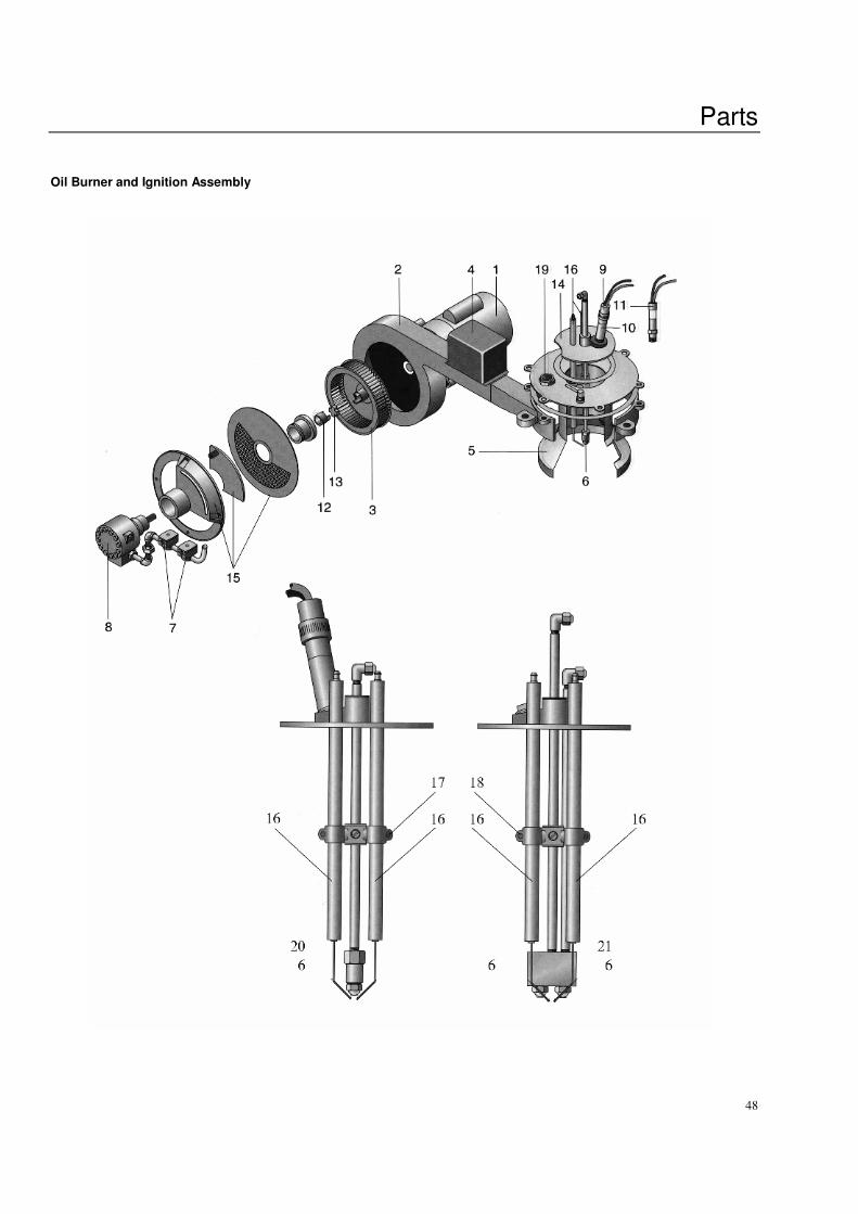
Parts
48
Oil Burner and Ignition Assembly
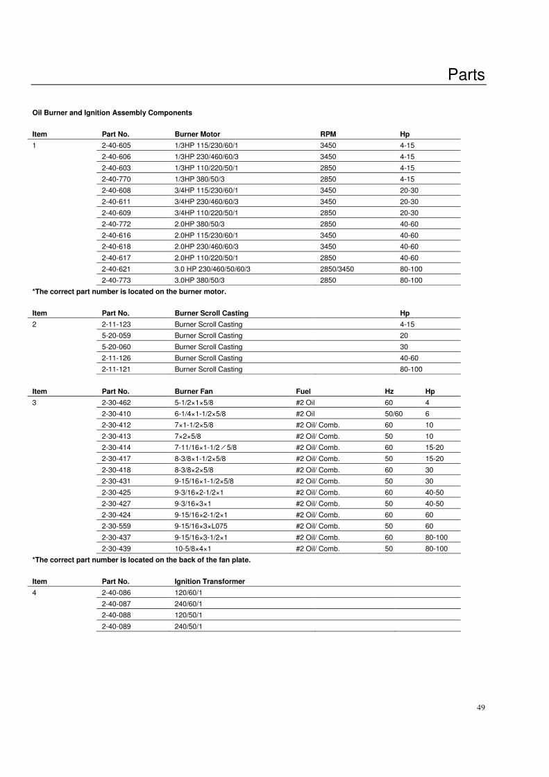
Parts
49
Oil Burner and Ignition Assembly Components
Item Part No. Burner Motor RPM Hp
1 2-40-605 1/3HP 115/230/60/1 3450 4-15
2-40-606 1/3HP 230/460/60/3 3450 4-15
2-40-603 1/3HP 110/220/50/1 2850 4-15
2-40-770 1/3HP 380/50/3 2850 4-15
2-40-608 3/4HP 115/230/60/1 3450 20-30
2-40-611 3/4HP 230/460/60/3 3450 20-30
2-40-609 3/4HP 110/220/50/1 2850 20-30
2-40-772 2.0HP 380/50/3 2850 40-60
2-40-616 2.0HP 115/230/60/1 3450 40-60
2-40-618 2.0HP 230/460/60/3 3450 40-60
2-40-617 2.0HP 110/220/50/1 2850 40-60
2-40-621 3.0 HP 230/460/50/60/3 2850/3450 80-100
2-40-773 3.0HP 380/50/3 2850 80-100
*The correct part number is located on the burner motor.
Item Part No. Burner Scroll Casting Hp
2 2-11-123 Burner Scroll Casting 4-15
5-20-059 Burner Scroll Casting 20
5-20-060 Burner Scroll Casting 30
2-11-126 Burner Scroll Casting 40-60
2-11-121 Burner Scroll Casting 80-100
Item Part No. Burner Fan Fuel Hz Hp
3 2-30-462 5-1/2×1×5/8 #2 Oil 60 4
2-30-410 6-1/4×1-1/2×5/8 #2 Oil 50/60 6
2-30-412 7×1-1/2×5/8 #2 Oil/ Comb. 60 10
2-30-413 7×2×5/8 #2 Oil/ Comb. 50 10
2-30-414 7-11/16×1-1/2×5/8 #2 Oil/ Comb. 60 15-20
2-30-417 8-3/8×1-1/2×5/8 #2 Oil/ Comb. 50 15-20
2-30-418 8-3/8×2×5/8 #2 Oil/ Comb. 60 30
2-30-431 9-15/16×1-1/2×5/8 #2 Oil/ Comb. 50 30
2-30-425 9-3/16×2-1/2×1 #2 Oil/ Comb. 60 40-50
2-30-427 9-3/16×3×1 #2 Oil/ Comb. 50 40-50
2-30-424 9-15/16×2-1/2×1 #2 Oil/ Comb. 60 60
2-30-559 9-15/16×3×L075 #2 Oil/ Comb. 50 60
2-30-437 9-15/16×3-1/2×1 #2 Oil/ Comb. 60 80-100
2-30-439 10-5/8×4×1 #2 Oil/ Comb. 50 80-100
*The correct part number is located on the back of the fan plate.
Item Part No. Ignition Transformer
4 2-40-086 120/60/1
2-40-087 240/60/1
2-40-088 120/50/1
2-40-089 240/50/1
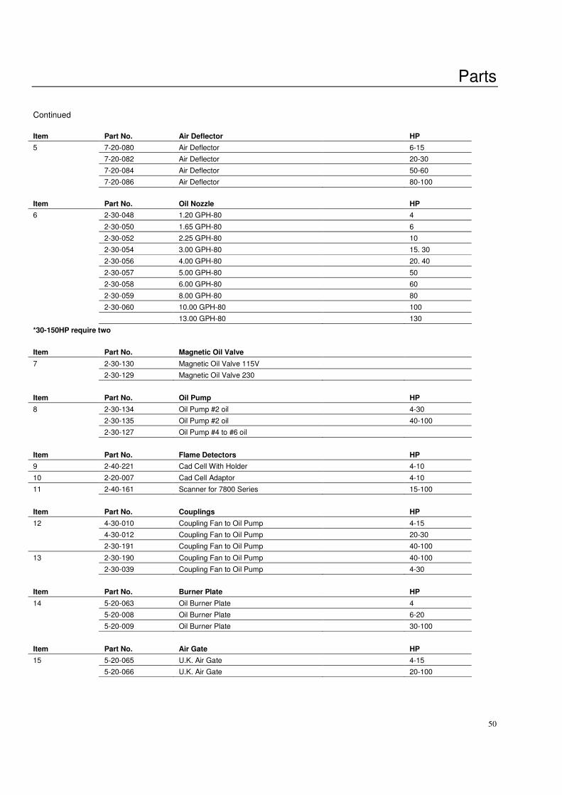
Parts
50
Continued
Item Part No. Air Deflector HP
5 7-20-080 Air Deflector 6-15
7-20-082 Air Deflector 20-30
7-20-084 Air Deflector 50-60
7-20-086 Air Deflector 80-100
Item Part No. Oil Nozzle HP
6 2-30-048 1.20 GPH-80 4
2-30-050 1.65 GPH-80 6
2-30-052 2.25 GPH-80 10
2-30-054 3.00 GPH-80 15. 30
2-30-056 4.00 GPH-80 20. 40
2-30-057 5.00 GPH-80 50
2-30-058 6.00 GPH-80 60
2-30-059 8.00 GPH-80 80
2-30-060 10.00 GPH-80 100
13.00 GPH-80 130
*30-150HP require two
Item Part No. Magnetic Oil Valve
7 2-30-130 Magnetic Oil Valve 115V
2-30-129 Magnetic Oil Valve 230
Item Part No. Oil Pump HP
8 2-30-134 Oil Pump #2 oil 4-30
2-30-135 Oil Pump #2 oil 40-100
2-30-127 Oil Pump #4 to #6 oil
Item Part No. Flame Detectors HP
9 2-40-221 Cad Cell With Holder 4-10
10 2-20-007 Cad Cell Adaptor 4-10
11 2-40-161 Scanner for 7800 Series 15-100
Item Part No. Couplings HP
12 4-30-010 Coupling Fan to Oil Pump 4-15
4-30-012 Coupling Fan to Oil Pump 20-30
2-30-191 Coupling Fan to Oil Pump 40-100
13 2-30-190 Coupling Fan to Oil Pump 40-100
2-30-039 Coupling Fan to Oil Pump 4-30
Item Part No. Burner Plate HP
14 5-20-063 Oil Burner Plate 4
5-20-008 Oil Burner Plate 6-20
5-20-009 Oil Burner Plate 30-100
Item Part No. Air Gate HP
15 5-20-065 U.K. Air Gate 4-15
5-20-066 U.K. Air Gate 20-100

Parts
51
Continued
Item Part No. Electrode Parts HP
16 2-20-021 11” Ignition Electrode 4-100
17 2-30-149 Ignition Electrode Holder 4-20
18 5-20-021 Ignition Electrode Holder 30-100
19 2-12-014 Pyrex Plate Glass 1” 4-100
20 2-20-003 Single Oil Nozzle Adaptor 4-20
2-20-004 Double Oil Nozzle Adaptor 30-100
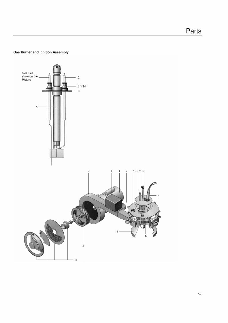
Parts
52
Gas Burner and Ignition Assembly
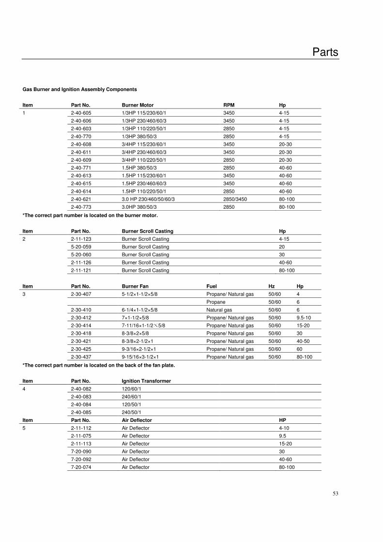
Parts
53
Gas Burner and Ignition Assembly Components
Item Part No. Burner Motor RPM Hp
1 2-40-605 1/3HP 115/230/60/1 3450 4-15
2-40-606 1/3HP 230/460/60/3 3450 4-15
2-40-603 1/3HP 110/220/50/1 2850 4-15
2-40-770 1/3HP 380/50/3 2850 4-15
2-40-608 3/4HP 115/230/60/1 3450 20-30
2-40-611 3/4HP 230/460/60/3 3450 20-30
2-40-609 3/4HP 110/220/50/1 2850 20-30
2-40-771 1.5HP 380/50/3 2850 40-60
2-40-613 1.5HP 115/230/60/1 3450 40-60
2-40-615 1.5HP 230/460/60/3 3450 40-60
2-40-614 1.5HP 110/220/50/1 2850 40-60
2-40-621 3.0 HP 230/460/50/60/3 2850/3450 80-100
2-40-773 3.0HP 380/50/3 2850 80-100
*The correct part number is located on the burner motor.
Item Part No. Burner Scroll Casting Hp
2 2-11-123 Burner Scroll Casting 4-15
5-20-059 Burner Scroll Casting 20
5-20-060 Burner Scroll Casting 30
2-11-126 Burner Scroll Casting 40-60
2-11-121 Burner Scroll Casting 80-100
Item Part No. Burner Fan Fuel Hz Hp
3 2-30-407 5-1/2×1-1/2×5/8 Propane/ Natural gas 50/60 4
Propane 50/60 6
2-30-410 6-1/4×1-1/2×5/8 Natural gas 50/60 6
2-30-412 7×1-1/2×5/8 Propane/ Natural gas 50/60 9.5-10
2-30-414 7-11/16×1-1/2×5/8 Propane/ Natural gas 50/60 15-20
2-30-418 8-3/8×2×5/8 Propane/ Natural gas 50/60 30
2-30-421 8-3/8×2-1/2×1 Propane/ Natural gas 50/60 40-50
2-30-425 9-3/16×2-1/2×1 Propane/ Natural gas 50/60 60
2-30-437 9-15/16×3-1/2×1 Propane/ Natural gas 50/60 80-100
*The correct part number is located on the back of the fan plate.
Item Part No. Ignition Transformer
4 2-40-082 120/60/1
2-40-083 240/60/1
2-40-084 120/50/1
2-40-085 240/50/1
Item Part No. Air Deflector HP
5 2-11-112 Air Deflector 4-10
2-11-075 Air Deflector 9.5
2-11-113 Air Deflector 15-20
7-20-090 Air Deflector 30
7-20-092 Air Deflector 40-60
7-20-074 Air Deflector 80-100
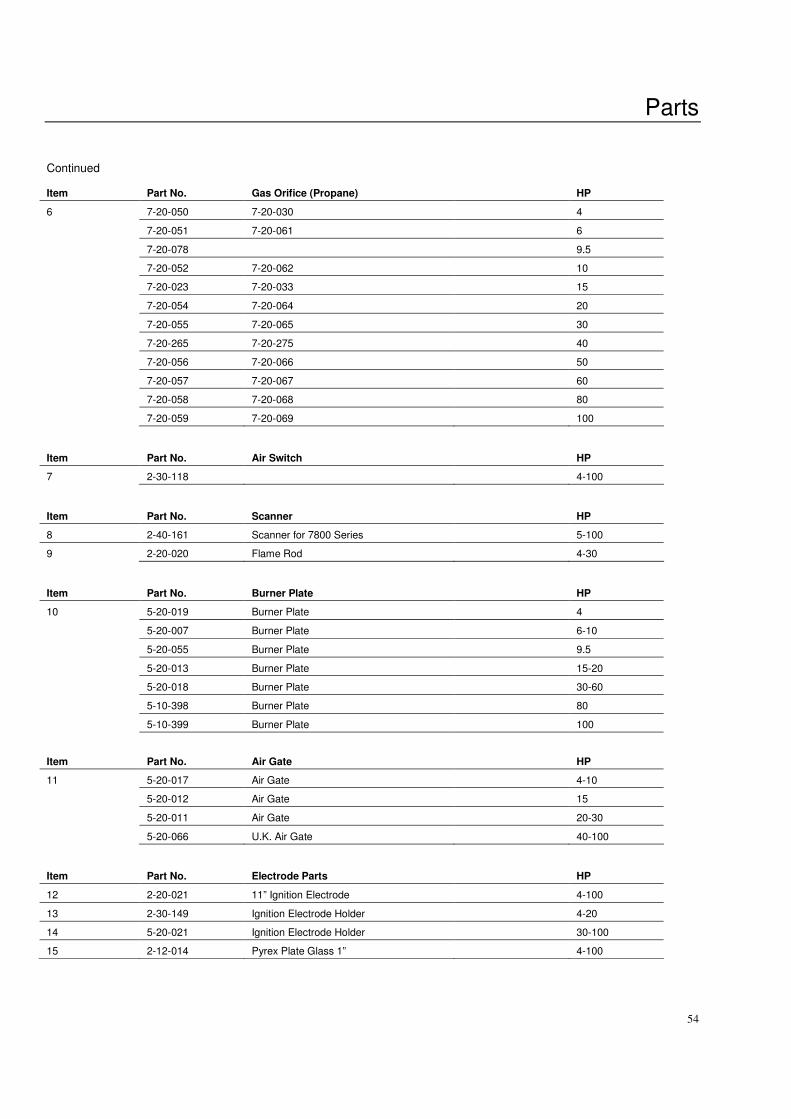
Parts
54
Continued
Item Part No. Gas Orifice (Propane) HP
6 7-20-050 7-20-030 4
7-20-051 7-20-061 6
7-20-078 9.5
7-20-052 7-20-062 10
7-20-023 7-20-033 15
7-20-054 7-20-064 20
7-20-055 7-20-065 30
7-20-265 7-20-275 40
7-20-056 7-20-066 50
7-20-057 7-20-067 60
7-20-058 7-20-068 80
7-20-059 7-20-069 100
Item Part No. Air Switch HP
7 2-30-118 4-100
Item Part No. Scanner HP
8 2-40-161 Scanner for 7800 Series 5-100
9 2-20-020 Flame Rod 4-30
Item Part No. Burner Plate HP
10 5-20-019 Burner Plate 4
5-20-007 Burner Plate 6-10
5-20-055 Burner Plate 9.5
5-20-013 Burner Plate 15-20
5-20-018 Burner Plate 30-60
5-10-398 Burner Plate 80
5-10-399 Burner Plate 100
Item
Part No.
Air Gate
HP
11 5-20-017 Air Gate 4-10
5-20-012 Air Gate 15
5-20-011 Air Gate 20-30
5-20-066 U.K. Air Gate 40-100
Item Part No. Electrode Parts HP
12 2-20-021 11” Ignition Electrode 4-100
13 2-30-149 Ignition Electrode Holder 4-20
14 5-20-021 Ignition Electrode Holder 30-100
15 2-12-014 Pyrex Plate Glass 1” 4-100
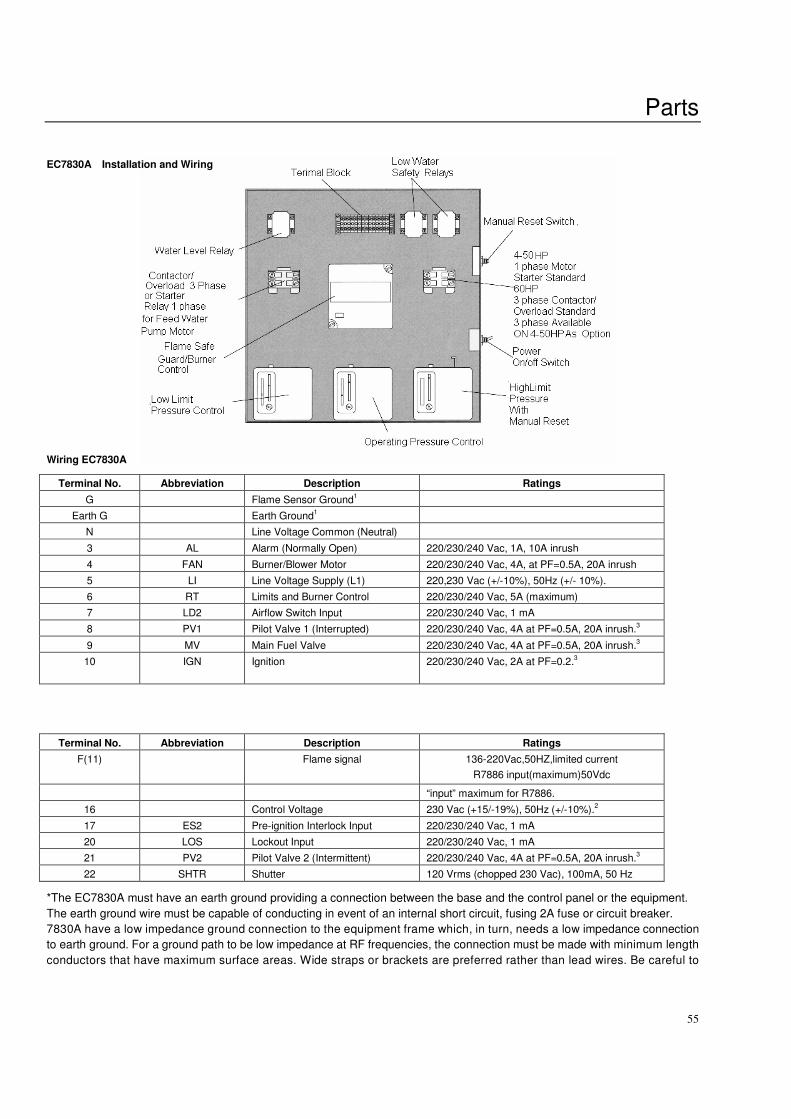
Parts
55
EC7830A Installation and Wiring
Wiring EC7830A
Terminal No. Abbreviation Description Ratings
G Flame Sensor Ground1
Earth G Earth Ground1
N Line Voltage Common (Neutral)
3 AL Alarm (Normally Open) 220/230/240 Vac, 1A, 10A inrush
4 FAN Burner/Blower Motor 220/230/240 Vac, 4A, at PF=0.5A, 20A inrush
5 LI Line Voltage Supply (L1) 220,230 Vac (+/-10%), 50Hz (+/- 10%).
6 RT Limits and Burner Control 220/230/240 Vac, 5A (maximum)
7 LD2 Airflow Switch Input 220/230/240 Vac, 1 mA
8 PV1 Pilot Valve 1 (Interrupted) 220/230/240 Vac, 4A at PF=0.5A, 20A inrush.3
9 MV Main Fuel Valve 220/230/240 Vac, 4A at PF=0.5A, 20A inrush.3
10
IGN
Ignition
220/230/240 Vac, 2A at PF=0.2.3
Terminal No. Abbreviation Description Ratings
F(11) Flame signal 136-220Vac,50HZ,limited current
R7886 input(maximum)50Vdc
“input” maximum for R7886.
16 Control Voltage 230 Vac (+15/-19%), 50Hz (+/-10%).2
17 ES2 Pre-ignition Interlock Input 220/230/240 Vac, 1 mA
20 LOS Lockout Input 220/230/240 Vac, 1 mA
21 PV2 Pilot Valve 2 (Intermittent) 220/230/240 Vac, 4A at PF=0.5A, 20A inrush.3
22 SHTR Shutter 120 Vrms (chopped 230 Vac), 100mA, 50 Hz
*The EC7830A must have an earth ground providing a connection between the base and the control panel or the equipment.
The earth ground wire must be capable of conducting in event of an internal short circuit, fusing 2A fuse or circuit breaker.
7830A have a low impedance ground connection to the equipment frame which, in turn, needs a low impedance connection
to earth ground. For a ground path to be low impedance at RF frequencies, the connection must be made with minimum length
conductors that have maximum surface areas. Wide straps or brackets are preferred rather than lead wires. Be careful to

Parts
56
ensure that mechanically tightened joints along the ground path, such as pipe or conduit threads or surfaces held together
with fasteners, are free of nonconductive coatings and are protected against mating surface corrosion.
*2000 W maximum connected load to EC7830A Assembly. Use section that more than 2.5mm2 soft wires to connect. The
power must insure the rated requires and fit voltage regulator power, otherwise not in warranty range.
*Total load current, excluding Burner motor and firing transformer outputs cannot exceed 5A, 25A inrush.
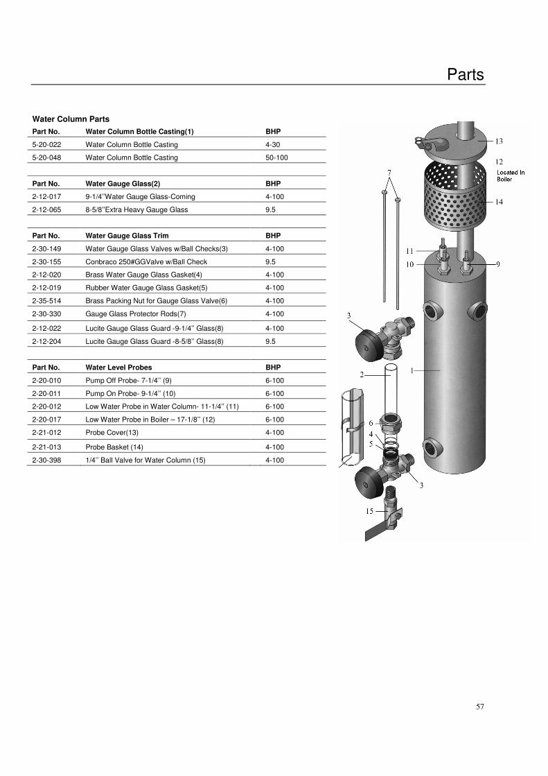
Parts
57
Water Column Parts
Part No. Water Column Bottle Casting(1) BHP
5-20-022 Water Column Bottle Casting 4-30
5-20-048 Water Column Bottle Casting 50-100
Part No. Water Gauge Glass(2) BHP
2-12-017 9-1/4’’Water Gauge Glass-Coming 4-100
2-12-065 8-5/8’’Extra Heavy Gauge Glass 9.5
Part No. Water Gauge Glass Trim BHP
2-30-149 Water Gauge Glass Valves w/Ball Checks(3) 4-100
2-30-155 Conbraco 250#GGValve w/Ball Check 9.5
2-12-020 Brass Water Gauge Glass Gasket(4) 4-100
2-12-019 Rubber Water Gauge Glass Gasket(5) 4-100
2-35-514 Brass Packing Nut for Gauge Glass Valve(6) 4-100
2-30-330 Gauge Glass Protector Rods(7) 4-100
2-12-022 Lucite Gauge Glass Guard -9-1/4’’ Glass(8) 4-100
2-12-204 Lucite Gauge Glass Guard -8-5/8’’ Glass(8) 9.5
Part No. Water Level Probes BHP
2-20-010 Pump Off Probe- 7-1/4’’ (9) 6-100
2-20-011 Pump On Probe- 9-1/4’’ (10) 6-100
2-20-012 Low Water Probe in Water Column- 11-1/4’’ (11) 6-100
2-20-017 Low Water Probe in Boiler – 17-1/8’’ (12) 6-100
2-21-012 Probe Cover(13) 4-100
2-21-013 Probe Basket (14) 4-100
2-30-398 1/4’’ Ball Valve for Water Column (15) 4-100
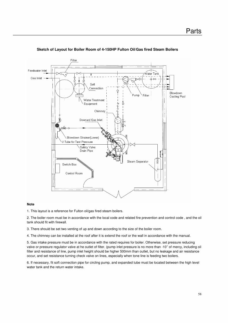
Parts
58
Sketch of Layout for Boiler Room of 4-150HP Fulton Oil/Gas fired Steam Boilers
Note
1. This layout is a reference for Fulton oil/gas fired steam boilers.
2. The boiler room must be in accordance with the local code and related fire prevention and control code , and the oil
tank should fit with firewall.
3. There should be set two venting of up and down according to the size of the boiler room.
4. The chimney can be installed at the roof after it is extend the roof or the wall in accordance with the manual.
5. Gas intake pressure must be in accordance with the rated requires for boiler. Otherwise, set pressure reducing
valve or pressure regulator valve at he outlet of filter. (pump inlet pressure is no more than -10’’ of mercy, including oil
filter and resistance of line, pump inlet height should be higher 500mm than outlet, but no leakage and air resistance
occur, and set resistance turning check valve on lines, especially when tone line is feeding two boilers.
6. If necessary, fit soft connection pipe for circling pump, and expanded tube must be located between the high level
water tank and the return water intake.

Warranty
59
Warranty
60
3 Year Conditional Warranty
On the Fulton Boiler Pressure Vessel Fulton Boiler Works. Inc. will repair or replace any Fulton pressure vessel which. Within three (3) years of the date
of shipment from factory, is found to be defective in workmanship or material, provided this equipment is installed,
operated and maintained by the buyer in accordance with the Fulton instruction manual and approved practices, and
that the water quality used in the system has been regularly checked to meet the standards for ideal and proper
boiler feedwater during the warranty period.
This warranty does not cover damage of failure that can be attributed to corrosion, (including oxygen pitting)
scale or dirt accumulations, or to low conditions. Follow feedwater and recommended treatment specifications as
detailed in section 1 of the instruction manual shipped with your boiler as well as maintenance procedures as listed in
section 4. This 3 year warranty applies only in the continental U.S.A and Canada. The warranty does not include labor
charges of any kind. In the event a failure is reported, Fulton will require an analysis of the boiler feedwater to
determine that acceptable water conditions are present at the installation site as well as documentation on the
feedwater treatment employed since the installation of the boiler.
Consult Fulton Boiler Works, Inc. for analysis of acceptable water conditions.
Feedwater treatment and proper daily blowdown procedures are very important in keeping your boiler heating
surfaces free of scale formation, pitting, oxygen corrosion and foaming or bouncing water. They will
recommend the proper treatment required for prolonging boiler life. A thorough boiler inspection should take
place during the first three months of operation to assess the effectiveness of boiler water treatment
techniques, including analysis of potential oxygen pitting. It is the owner's responsibility to assure safe
operation of the boiler. To avoid corrosion, scale or dirt accumulations, it is recommended that a daily blow
down procedure be instituted. The boiler power should be left on during daily blow down so that correct
operation in the low water relay may be checked. While blowing down the boiler, the pressure will drop
significantly. While blowing boiler down with power on, it is normal to hear the boiler feed pump come on. The
burner should not turn on. If the burner does come on, turn the boiler off and contact our factory immediately.
Corrosive acid and chlorine based chemicals in the atmosphere can be damaging to this boiler. It is the
owner's responsibility to have the boiler room periodically tested to assure these damaging chemicals are not
present.
1 Year (12 Month) Standard Warranty
A. Fulton Boiler Works, Inc. will repair or replace any other part of this boiler of our manufacture which within twelve
months of the date of shipment from factory is found to be defective in workmanship or material, provided the
equipment has been installed, operated and maintained by the buyer in accordance with the operating instruction
manual provided with the equipment and generally accepted approved practices, and on the provision that the buyer
gives proper notification in writing as soon as the defect take place, and that he has properly filled out and returned his
warranty card. This warranty does not include labor charges of any kind. Follow maintenance instructions as listed in
the “Instruction Book.”
B. But Fulton Boiler Works, Inc. does not provide any warranty for products manufactured by others.
C. The electrical elements for Fulton boilers request the working voltage in the range of 220V±10%,if the user can not
ensure this request of voltage safety, voltage regulator power must be fitted. Otherwise, the electrical elements
damaging caused by voltage not as request is not in the range of warranty.
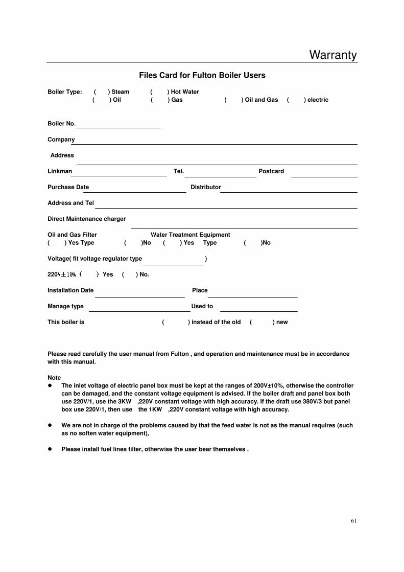
Warranty
61
Files Card for Fulton Boiler Users
Boiler Type: ( ) Steam ( ) Hot Water
( ) Oil ( ) Gas ( ) Oil and Gas ( ) electric
Boiler No.
Company
Address
Linkman Tel. Postcard
Purchase Date Distributor
Address and Tel
Direct Maintenance charger
Oil and Gas Filter Water Treatment Equipment
( ) Yes Type ( )No ( ) Yes Type ( )No
Voltage( fit voltage regulator type )
220VVVV±±±±10% ( ) 10% ( ) 10% ( ) 10% ( ) Yes ( ) No.
Installation Date Place
Manage type Used to
This boiler is ( ) instead of the old ( ) new
Please read carefully the user manual from Fulton , and operation and maintenance must be in accordance
with this manual.
Note
� The inlet voltage of electric panel box must be kept at the ranges of 200V±10%, otherwise the controller
can be damaged, and the constant voltage equipment is advised. If the boiler draft and panel box both
use 220V/1, use the 3KW ,220V constant voltage with high accuracy. If the draft use 380V/3 but panel
box use 220V/1, then use the 1KW ,220V constant voltage with high accuracy.
� We are not in charge of the problems caused by that the feed water is not as the manual requires (such
as no soften water equipment),
� Please install fuel lines filter, otherwise the user bear themselves .
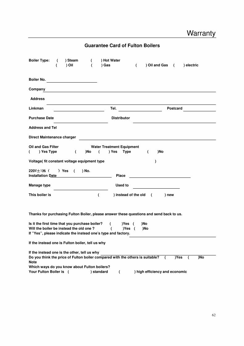
Warranty
62
Guarantee Card of Fulton Boilers
Boiler Type: ( ) Steam ( ) Hot Water
( ) Oil ( ) Gas ( ) Oil and Gas ( ) electric
Boiler No.
Company
Address
Linkman Tel. Postcard
Purchase Date Distributor
Address and Tel
Direct Maintenance charger
Oil and Gas Filter Water Treatment Equipment
( ) Yes Type ( )No ( ) Yes Type ( )No
Voltage( fit constant voltage equipment type )
220VVVV±±±±10% ( ) 10% ( ) 10% ( ) 10% ( ) Yes ( ) No.
Installation Date Place
Manage type Used to
This boiler is ( ) instead of the old ( ) new
Thanks for purchasing Fulton Boiler, please answer these questions and send back to us.
Is it the first time that you purchase boiler? ( )Yes ( )No
Will the boiler be instead the old one ? ( )Yes ( )No
If ”Yes’’, please indicate the instead one’s type and factory.
If the instead one is Fulton boiler, tell us why
If the instead one is the other, tell us why
Do you think the price of Fulton boiler compared with the others is suitable? ( )Yes ( )No
Note
Which ways do you know about Fulton boilers?
Your Fulton Boiler is ( ) standard ( ) high efficiency and economic
Warranty
63
Guarantee Card of Fulton Boiler
Which affect you the deepest among the character of Fulton boiler.
( ) Design of vertical with no tube ( ) The operation is simple.
( ) PV 3years warn y ( ) Maintenance easily
( ) Steel components of electric boiler ( ) efficiency
( ) Burner with special design of Fulton ( ) safety
Talk about the impression to Fulton with simply words:
Do you still purchase Fulton boiler? ( ) yes ( ) No
Why? Please tell us the reason.
Please read carefully the user manual from Fulton , and operation and maintenance must be in accordance
with this manual.
Note
� The inlet voltage of electric panel box must be kept at the ranges of 200V±10%, otherwise the controller
can be damaged, and the constant voltage equipment is advised. If the boiler draft and panel box both
use 220V/1, use the 3KW ,220V constant voltage with high accuracy. If the draft use 380V/3 but panel
box use 220V/1, then use the 1KW ,220V constant voltage with high accuracy.
� We are not in charge of the problems caused by that the feed water is not as the manual requires (such
as no soften water equipment),
� Please install fuel lines filter, otherwise the user bear themselves .
It will be valid that this card must be written and sent back to Hang Zhou Fulton Thermal Equipment co., Ltd.
after purchases 40days. (may be copies)