Embed Size (px)
Citation preview

Serial Programming Guide for POSIX Operating Systems5th Edition, 2nd Revision
Michael R. SweetCopyright 1994−1999, All Rights Reserved.


Table of ContentsIntroduction.........................................................................................................................................................1
Chapter 1, Basics of Serial Communications...................................................................................................3What Are Serial Communications?.........................................................................................................3What Is RS−232?.....................................................................................................................................4
Signal Definitions.......................................................................................................................4Asynchronous Communications..............................................................................................................5
What Are Full Duplex and Half Duplex?...................................................................................6Flow Control...............................................................................................................................6What Is a Break?.........................................................................................................................7
Synchronous Communications................................................................................................................7Accessing Serial Ports..............................................................................................................................7
Serial Port Files...........................................................................................................................7Opening a Serial Port..................................................................................................................8Writing Data to the Port..............................................................................................................9Reading Data from the Port........................................................................................................9Closing a Serial Port...................................................................................................................9
Chapter 2, Configuring the Serial Port...........................................................................................................11The POSIX Terminal Interface..............................................................................................................11
Control Options.........................................................................................................................12Local Options............................................................................................................................15Input Options............................................................................................................................16Output Options..........................................................................................................................17Control Characters....................................................................................................................18
Chapter 3, MODEM Communications...........................................................................................................21What Is a MODEM?..............................................................................................................................21Communicating With a MODEM..........................................................................................................21
Standard MODEM Commands.................................................................................................22Common MODEM Communication Problems........................................................................23
Chapter 4, Advanced Serial Programming....................................................................................................25Serial Port IOCTLs................................................................................................................................25
Getting the Control Signals.......................................................................................................26Setting the Control Signals.......................................................................................................27Getting the Number of Bytes Available...................................................................................27
Selecting Input from a Serial Port..........................................................................................................27The SELECT System Call........................................................................................................28Using the SELECT System Call...............................................................................................28Using SELECT with the X Intrinsics Library..........................................................................29
Appendix A, Pinouts.........................................................................................................................................31RS−232 Pinouts.....................................................................................................................................31RS−422 Pinouts.....................................................................................................................................32RS−574 (IBM PC/AT) Pinouts..............................................................................................................32SGI Pinouts............................................................................................................................................33
Serial Programming Guide for POSIX Operating Systems
Introduction i

Table of ContentsAppendix B, ASCII Control Codes.................................................................................................................35
Control Codes........................................................................................................................................35
Serial Programming Guide for POSIX Operating Systems
ii Appendix B, ASCII Control Codes

Introduction
The Serial Programming Guide for POSIX Operating Systems will teach you how to successfully, efficiently,and portably program the serial ports on your UNIX® workstation or PC. Each chapter provides programmingexamples that use the POSIX (Portable Standard for UNIX) terminal control functions and should work withvery few modifications under IRIX®, HP−UX, SunOS®, Solaris®, Digital UNIX®, Linux®, and most otherUNIX operating systems. The biggest difference between operating systems that you will find is the filenamesused for serial port device and lock files.
This guide is organized into the following chapters and appendices:
Chapter 1, Basics of Serial Programming• Chapter 2, Configuring the Serial Port• Chapter 3, Talking to MODEMs• Chapter 4, Advanced Serial Programming• Appendix A, RS−232 Pinouts• Appendix B, ASCII Control Codes•
Introduction 1

Serial Programming Guide for POSIX Operating Systems
2 Introduction

Chapter 1, Basics of Serial Communications
This chapter introduces serial communications, RS−232 and other standards that are used on most computersas well as how to access a serial port from a C program.
What Are Serial Communications?
Computers transfer information (data) one or more bits at a time. Serial refers to the transfer of data one bit ata time. Serial communications include most network devices, keyboards, mice, MODEMs, and terminals.
When doing serial communications each word (i.e. byte or character) of data you send or receive is sent onebit at a time. Each bit is either on or off. The terms you'll hear sometimes are mark for the on state and spacefor the off state.
The speed of the serial data is most often expressed as bits−per−second ("bps") or baudot rate ("baud"). Thisjust represents the number of ones and zeroes that can be sent in one second. Back at the dawn of thecomputer age, 300 baud was considered fast, but today computers can handle RS−232 speeds as high as430,800 baud! When the baud rate exceeds 1,000, you'll usually see the rate shown in kilobaud, or kbps (e.g.9.6k, 19.2k, etc). For rates above 1,000,000 that rate is shown in megabaud, or Mbps (e.g. 1.5Mbps).
When referring to serial devices or ports, they are either labeled as Data Communications Equipment ("DCE")or Data Terminal Equipment ("DTE"). The difference between these is simple − every signal pair, liketransmit and receive, is swapped. When connecting two DTE or two DCE interfaces together, a serialnull−MODEM cable or adapter is used that swaps the signal pairs.
Chapter 1, Basics of Serial Communications 3

What Is RS−232?
RS−232 is a standard electrical interface for serial communications defined by the Electronic IndustriesAssociation ("EIA"). RS−232 actually comes in 3 different flavors (A, B, and C) with each one defining adifferent voltage range for the on and off levels. The most commonly used variety is RS−232C, which definesa mark (on) bit as a voltage between −3V and −12V and a space (off) bit as a voltage between +3V and +12V.The RS−232C specification says these signals can go about 25 feet (8m) before they become unusable. Youcan usually send signals a bit farther than this as long as the baud is low enough.
Besides wires for incoming and outgoing data, there are others that provide timing, status, and handshaking:
Table 1 − RS−232 Pin Assignments
Pin Description Pin Description Pin Description Pin Description Pin Description
1 Earth Ground6DSR −Data SetReady
11 Unassigned 16 Secondary RXD21Signal QualityDetect
2TXD −TransmittedData
7GND −LogicGround
12 Secondary DCD17 Receiver Clock 22 Ring Detect
3RXD −ReceivedData
8
DCD −DataCarrierDetect
13 Secondary CTS18 Unassigned 23Data RateSelect
4RTS −Request ToSend
9 Reserved 14 Secondary TXD19 Secondary RTS24 Transmit Clock
5CTS − ClearTo Send
10 Reserved 15 Transmit Clock 20DTR − DataTerminal Ready
25 Unassigned
Two standards for serial interfaces you may also see are RS−422 and RS−574. RS−422 uses lower voltagesand differential signals to allow cable lengths up to about 1000ft (300m). RS−574 defines the 9−pin PC serialconnector and voltages.
Signal Definitions
The RS−232 standard defines some 18 different signals for serial communications. Of these, only six aregenerally available in the UNIX environment.
GND − Logic Ground
Technically the logic ground is not a signal, but without it none of the other signals will operate. Basically, thelogic ground acts as a reference voltage so that the electronics know which voltages are positive or negative.
TXD − Transmitted Data
The TXD signal carries data transmitted from your workstation to the computer or device on the other end(like a MODEM). A mark voltage is interpreted as a value of 1, while a space voltage is interpreted as a valueof 0.
Serial Programming Guide for POSIX Operating Systems
4 What Is RS−232?
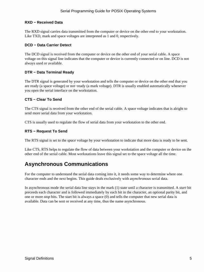
RXD − Received Data
The RXD signal carries data transmitted from the computer or device on the other end to your workstation.Like TXD, mark and space voltages are interpreted as 1 and 0, respectively.
DCD − Data Carrier Detect
The DCD signal is received from the computer or device on the other end of your serial cable. A spacevoltage on this signal line indicates that the computer or device is currently connected or on line. DCD is notalways used or available.
DTR − Data Terminal Ready
The DTR signal is generated by your workstation and tells the computer or device on the other end that youare ready (a space voltage) or not−ready (a mark voltage). DTR is usually enabled automatically wheneveryou open the serial interface on the workstation.
CTS − Clear To Send
The CTS signal is received from the other end of the serial cable. A space voltage indicates that is alright tosend more serial data from your workstation.
CTS is usually used to regulate the flow of serial data from your workstation to the other end.
RTS − Request To Send
The RTS signal is set to the space voltage by your workstation to indicate that more data is ready to be sent.
Like CTS, RTS helps to regulate the flow of data between your workstation and the computer or device on theother end of the serial cable. Most workstations leave this signal set to the space voltage all the time.
Asynchronous Communications
For the computer to understand the serial data coming into it, it needs some way to determine where onecharacter ends and the next begins. This guide deals exclusively with asynchronous serial data.
In asynchronous mode the serial data line stays in the mark (1) state until a character is transmitted. A start bitpreceeds each character and is followed immediately by each bit in the character, an optional parity bit, andone or more stop bits. The start bit is always a space (0) and tells the computer that new serial data isavailable. Data can be sent or received at any time, thus the name asynchronous.
Serial Programming Guide for POSIX Operating Systems
Signal Definitions 5

Figure 1 − Asynchronous Data Transmission
The optional parity bit is a simple sum of the data bits indicating whether or not the data contains an even orodd number of 1 bits. With even parity, the parity bit is 0 if there is an even number of 1's in the character.With odd parity, the parity bit is 0 if there is an odd number of 1's in the data. You may also hear the termsspace parity, mark parity, and no parity. Space parity means that the parity bit is always 0, while mark paritymeans the bit is always 1. No parity means that no parity bit is present or transmitted.
The remaining bits are called stop bits. There can be 1, 1.5, or 2 stop bits between characters and they alwayshave a value of 1. Stop bits traditionally were used to give the computer time to process the previouscharacter, but now only serve to synchronize the receiving computer to the incoming characters.
Asynchronous data formats are usually expressed as "8N1", "7E1", and so forth. These stand for "8 data bits,no parity, 1 stop bit" and "7 data bits, even parity, 1 stop bit" respectively.
What Are Full Duplex and Half Duplex?
Full duplex means that the computer can send and receive data simultaneously − there are two separate datachannels (one coming in, one going out).
Half duplex means that the computer cannot send or receive data at the same time. Usually this means there isonly a single data channel to talk over. This does not mean that any of the RS−232 signals are not used.Rather, it usually means that the communications link uses some standard other than RS−232 that does notsupport full duplex operation.
Flow Control
It is often necessary to regulate the flow of data when transferring data between two serial interfaces. This canbe due to limitations in an intermediate serial communications link, one of the serial interfaces, or somestorage media. Two methods are commonly used for asynchronous data.
The first method is often called "software" flow control and uses special characters to start (XON or DC1, 021octal) or stop (XOFF or DC3, 023 octal) the flow of data. These characters are defined in the AmericanStandard Code for Information Interchange ("ASCII"). While these codes are useful when transferring textualinformation, they cannot be used when transferring other types of information without special programming.
The second method is called "hardware" flow control and uses the RS−232 CTS and RTS signals instead ofspecial characters. The receiver sets CTS to the space voltage when it is ready to receive more data and to themark voltage when it is not ready. Likewise, the sender sets RTS to the space voltage when it is ready to sendmore data. Because hardware flow control uses a separate set of signals, it is much faster than software flowcontrol which needs to send or receive multiple bits of information to do the same thing. CTS/RTS flowcontrol is not supported by all hardware or operating systems.
Serial Programming Guide for POSIX Operating Systems
6 What Are Full Duplex and Half Duplex?
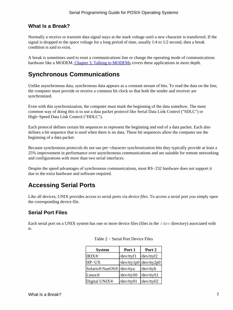
What Is a Break?
Normally a receive or transmit data signal stays at the mark voltage until a new character is transferred. If thesignal is dropped to the space voltage for a long period of time, usually 1/4 to 1/2 second, then a breakcondition is said to exist.
A break is sometimes used to reset a communications line or change the operating mode of communicationshardware like a MODEM. Chapter 3, Talking to MODEMs covers these applications in more depth.
Synchronous Communications
Unlike asynchronous data, synchronous data appears as a constant stream of bits. To read the data on the line,the computer must provide or receive a common bit clock so that both the sender and receiver aresynchronized.
Even with this synchronization, the computer must mark the beginning of the data somehow. The mostcommon way of doing this is to use a data packet protocol like Serial Data Link Control ("SDLC") orHigh−Speed Data Link Control ("HDLC").
Each protocol defines certain bit sequences to represent the beginning and end of a data packet. Each alsodefines a bit sequence that is used when there is no data. These bit sequences allow the computer see thebeginning of a data packet.
Because synchronous protocols do not use per−character synchronization bits they typically provide at least a25% improvement in performance over asynchronous communications and are suitable for remote networkingand configurations with more than two serial interfaces.
Despite the speed advantages of synchronous communications, most RS−232 hardware does not support itdue to the extra hardware and software required.
Accessing Serial Ports
Like all devices, UNIX provides access to serial ports via device files. To access a serial port you simply openthe corresponding device file.
Serial Port Files
Each serial port on a UNIX system has one or more device files (files in the /dev directory) associated withit:
Table 2 − Serial Port Device Files
System Port 1 Port 2
IRIX® /dev/ttyf1 /dev/ttyf2
HP−UX /dev/tty1p0/dev/tty2p0
Solaris®/SunOS®/dev/ttya /dev/ttyb
Linux® /dev/ttyS0 /dev/ttyS1
Digital UNIX® /dev/tty01 /dev/tty02
Serial Programming Guide for POSIX Operating Systems
What Is a Break? 7

Opening a Serial Port
Since a serial port is a file, the open(2) function is used to access it. The one hitch with UNIX is that devicefiles are usually not accessable by normal users. Workarounds include changing the access permissions to thefile(s) in question, running your program as the super−user (root), or making your program set−userid so thatit runs as the owner of the device file.
For now we'll assume that the file is accessable by all users. The code to open serial port 1 on an sgi®workstation running IRIX is:
Listing 1 − Opening a serial port.
#include <stdio.h> /* Standard input/output definitions */#include <string.h> /* String function definitions */#include <unistd.h> /* UNIX standard function definitions */#include <fcntl.h> /* File control definitions */#include <errno.h> /* Error number definitions */#include <termios.h> /* POSIX terminal control definitions */
/* * 'open_port()' − Open serial port 1. * * Returns the file descriptor on success or −1 on error. */
intopen_port(void){ int fd; /* File descriptor for the port */
fd = open("/dev/ttyf1", O_RDWR | O_NOCTTY | O_NDELAY); if (fd == −1) { /* * Could not open the port. */
perror("open_port: Unable to open /dev/ttyf1 − "); } else fcntl(fd, F_SETFL, 0);
return (fd);}
Other systems would require the corresponding device file name, but otherwise the code is the same.
Open Options
You'll notice that when we opened the device file we used two other flags along with the read+write mode:
fd = open("/dev/ttyf1", O_RDWR | O_NOCTTY | O_NDELAY);
The O_NOCTTY flag tells UNIX that this program doesn't want to be the "controlling terminal" for that port.If you don't specify this then any input (such as keyboard abort signals and so forth) will affect your process.
Serial Programming Guide for POSIX Operating Systems
8 Opening a Serial Port

Programs like getty(1M/8) use this feature when starting the login process, but normally a user program doesnot want this behavior.
The O_NDELAY flag tells UNIX that this program doesn't care what state the DCD signal line is in − whetherthe other end of the port is up and running. If you do not specify this flag, your process will be put to sleepuntil the DCD signal line is the space voltage.
Writing Data to the Port
Writing data to the port is easy − just use the write(2) system call to send data it:
n = write(fd, "ATZ\r", 4);if (n < 0) fputs("write() of 4 bytes failed!\n", stderr);
The write function returns the number of bytes sent or −1 if an error occurred. Usually the only error you'llrun into is EIO when a MODEM or data link drops the Data Carrier Detect (DCD) line. This condition willpersist until you close the port.
Reading Data from the Port
Reading data from a port is a little trickier. When you operate the port in raw data mode, each read(2) systemcall will return however many characters are actually available in the serial input buffers. If no characters areavailable, the call will block (wait) until characters come in, an interval timer expires, or an error occurs. Theread function can be made to return immediately by doing the following:
fcntl(fd, F_SETFL, FNDELAY);
The FNDELAY option causes the read function to return 0 if no characters are available on the port. To restorenormal (blocking) behavior, call fcntl() without the FNDELAY option:
fcntl(fd, F_SETFL, 0);
This is also used after opening a serial port with the O_NDELAY option.
Closing a Serial Port
To close the serial port, just use the close system call:
close(fd);
Closing a serial port will also usually set the DTR signal low which causes most MODEMs to hang up.
Serial Programming Guide for POSIX Operating Systems
Writing Data to the Port 9

Serial Programming Guide for POSIX Operating Systems
10 Writing Data to the Port

Chapter 2, Configuring the Serial Port
This chapter discusses how to configure a serial port from C using the POSIX termios interface.
The POSIX Terminal Interface
Most systems support the POSIX terminal (serial) interface for changing parameters such as baud rate,character size, and so on. The first thing you need to do is include the file <termios.h>; this defines theterminal control structure as well as the POSIX control functions.
The two most important POSIX functions are tcgetattr(3) and tcsetattr(3). These get and set terminalattributes, respectively; you provide a pointer to a termios structure that contains all of the serial optionsavailable:
Table 3 − Termios Structure Members
Member Description
c_cflag Control options
c_lflag Line options
c_iflag Input options
c_oflag Output options
c_cc Control characters
c_ispeed Input baud (new interface)
c_ospeed Output baud (new interface)
Chapter 2, Configuring the Serial Port 11

Control Options
The c_cflag member controls the baud rate, number of data bits, parity, stop bits, and hardware flow control.There are constants for all of the supported configurations.
Table 4 − Constants for the c_cflag Member
Constant Description
CBAUD Bit mask for baud rate
B0 0 baud (drop DTR)
B50 50 baud
B75 75 baud
B110 110 baud
B134 134.5 baud
B150 150 baud
B200 200 baud
B300 300 baud
B600 600 baud
B1200 1200 baud
B1800 1800 baud
B2400 2400 baud
B4800 4800 baud
B9600 9600 baud
B19200 19200 baud
B38400 38400 baud
B57600 57,600 baud
B76800 76,800 baud
B115200 115,200 baud
EXTA External rate clock
EXTB External rate clock
CSIZE Bit mask for data bits
CS5 5 data bits
CS6 6 data bits
CS7 7 data bits
CS8 8 data bits
CSTOPB 2 stop bits (1 otherwise)
CREAD Enable receiver
PARENB Enable parity bit
PARODD Use odd parity instead of even
HUPCL Hangup (drop DTR) on last close
CLOCALLocal line − do not change "owner"of port
LOBLK Block job control output
Serial Programming Guide for POSIX Operating Systems
12 Control Options
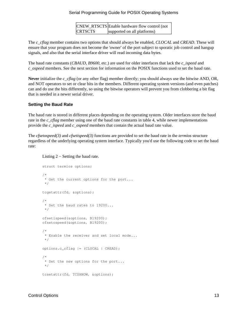
CNEW_RTSCTSCRTSCTS
Enable hardware flow control (notsupported on all platforms)
The c_cflag member contains two options that should always be enabled, CLOCAL and CREAD. These willensure that your program does not become the 'owner' of the port subject to sporatic job control and hangupsignals, and also that the serial interface driver will read incoming data bytes.
The baud rate constants (CBAUD, B9600, etc.) are used for older interfaces that lack the c_ispeed andc_ospeed members. See the next section for information on the POSIX functions used to set the baud rate.
Never initialize the c_cflag (or any other flag) member directly; you should always use the bitwise AND, OR,and NOT operators to set or clear bits in the members. Different operating system versions (and even patches)can and do use the bits differently, so using the bitwise operators will prevent you from clobbering a bit flagthat is needed in a newer serial driver.
Setting the Baud Rate
The baud rate is stored in different places depending on the operating system. Older interfaces store the baudrate in the c_cflag member using one of the baud rate constants in table 4, while newer implementationsprovide the c_ispeed and c_ospeed members that contain the actual baud rate value.
The cfsetospeed(3) and cfsetispeed(3) functions are provided to set the baud rate in the termios structureregardless of the underlying operating system interface. Typically you'd use the following code to set the baudrate:
Listing 2 − Setting the baud rate.
struct termios options;
/* * Get the current options for the port... */
tcgetattr(fd, &options);
/* * Set the baud rates to 19200... */
cfsetispeed(&options, B19200);cfsetospeed(&options, B19200);
/* * Enable the receiver and set local mode... */
options.c_cflag |= (CLOCAL | CREAD);
/* * Set the new options for the port... */
tcsetattr(fd, TCSANOW, &options);
Serial Programming Guide for POSIX Operating Systems
Control Options 13

The tcgetattr(3) function fills the termios structure you provide with the current serial port configuration.After we set the baud rates and enable local mode and serial data receipt, we select the new configurationusing tcsetattr(3). The TCSANOW constant specifies that all changes should occur immediately withoutwaiting for output data to finish sending or input data to finish receiving. There are other constants to wait forinput and output to finish or to flush the input and output buffers.
Most systems do not support different input and output speeds, so be sure to set both to the same value formaximum portability.
Table 5 − Constants for tcsetattr
Constant Description
TCSANOWMake changes now without waiting fordata to complete
TCSADRAINWait until everything has beentransmitted
TCSAFLUSHFlush input and output buffers andmake the change
Setting the Character Size
Unlike the baud rate, there is no convienience function to set the character size. Instead you must do a littlebitmasking to set things up. The character size is specified in bits:
options.c_cflag &= ~CSIZE; /* Mask the character size bits */options.c_cflag |= CS8; /* Select 8 data bits */
Setting Parity Checking
Like the character size you must manually set the parity enable and parity type bits. UNIX serial driverssupport even, odd, and no parity bit generation. Space parity can be simulated with clever coding.
No parity (8N1):•
options.c_cflag &= ~PARENBoptions.c_cflag &= ~CSTOPBoptions.c_cflag &= ~CSIZE;options.c_cflag |= CS8;
Even parity (7E1):•
options.c_cflag |= PARENBoptions.c_cflag &= ~PARODDoptions.c_cflag &= ~CSTOPBoptions.c_cflag &= ~CSIZE;options.c_cflag |= CS7;
Odd parity (7O1):•
options.c_cflag |= PARENBoptions.c_cflag |= PARODDoptions.c_cflag &= ~CSTOPB
Serial Programming Guide for POSIX Operating Systems
14 Control Options

options.c_cflag &= ~CSIZE;options.c_cflag |= CS7;
Space parity is setup the same as no parity (7S1):•
options.c_cflag &= ~PARENBoptions.c_cflag &= ~CSTOPBoptions.c_cflag &= ~CSIZE;options.c_cflag |= CS8;
Setting Hardware Flow Control
Some versions of UNIX support hardware flow control using the CTS (Clear To Send) and RTS (Request ToSend) signal lines. If the CNEW_RTSCTS or CRTSCTS constants are defined on your system then hardwareflow control is probably supported. Do the following to enable hardware flow control:
options.c_cflag |= CNEW_RTSCTS; /* Also called CRTSCTS */
Similarly, to disable hardware flow control:
options.c_cflag &= ~CNEW_RTSCTS;
Local Options
The local modes member c_lflag controls how input characters are managed by the serial driver. In generalyou will configure the c_lflag member for canonical or raw input.
Table 6 − Constants for the c_lflag Member
Constant Description
ISIGEnable SIGINTR, SIGSUSP, SIGDSUSP,and SIGQUIT signals
ICANON Enable canonical input (else raw)
XCASE Map uppercase \lowercase (obsolete)
ECHO Enable echoing of input characters
ECHOE Echo erase character as BS−SP−BS
ECHOK Echo NL after kill character
ECHONL Echo NL
NOFLSHDisable flushing of input buffers afterinterrupt or quit characters
IEXTEN Enable extended functions
ECHOCTLEcho control characters as ^char anddelete as ~?
ECHOPRTEcho erased character as character erased
ECHOKE BS−SP−BS entire line on line kill
FLUSHO Output being flushed
PENDINRetype pending input at next read or inputchar
Serial Programming Guide for POSIX Operating Systems
Control Options 15
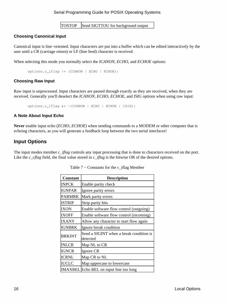
TOSTOP Send SIGTTOU for background output
Choosing Canonical Input
Canonical input is line−oriented. Input characters are put into a buffer which can be edited interactively by theuser until a CR (carriage return) or LF (line feed) character is received.
When selecting this mode you normally select the ICANON, ECHO, and ECHOE options:
options.c_lflag |= (ICANON | ECHO | ECHOE);
Choosing Raw Input
Raw input is unprocessed. Input characters are passed through exactly as they are received, when they arereceived. Generally you'll deselect the ICANON, ECHO, ECHOE, and ISIG options when using raw input:
options.c_lflag &= ~(ICANON | ECHO | ECHOE | ISIG);
A Note About Input Echo
Never enable input echo (ECHO, ECHOE) when sending commands to a MODEM or other computer that isechoing characters, as you will generate a feedback loop between the two serial interfaces!
Input Options
The input modes member c_iflag controls any input processing that is done to characters received on the port.Like the c_cflag field, the final value stored in c_iflag is the bitwise OR of the desired options.
Table 7 − Constants for the c_iflag Member
Constant Description
INPCK Enable parity check
IGNPAR Ignore parity errors
PARMRK Mark parity errors
ISTRIP Strip parity bits
IXON Enable software flow control (outgoing)
IXOFF Enable software flow control (incoming)
IXANY Allow any character to start flow again
IGNBRK Ignore break condition
BRKINTSend a SIGINT when a break condition isdetected
INLCR Map NL to CR
IGNCR Ignore CR
ICRNL Map CR to NL
IUCLC Map uppercase to lowercase
IMAXBEL Echo BEL on input line too long
Serial Programming Guide for POSIX Operating Systems
16 Local Options

Setting Input Parity Options
You should enable input parity checking when you have enabled parity in the c_cflag member (PARENB).The revelant constants for input parity checking are INPCK, IGNPAR, PARMRK, and ISTRIP. Generally youwill select INPCK and ISTRIP to enable checking and stripping of the parity bit:
options.c_iflag |= (INPCK | ISTRIP);
IGNPAR is a somewhat dangerous option that tells the serial driver to ignore parity errors and pass theincoming data through as if no errors had occurred. This can be useful for testing the quality of acommunications link, but in general is not used for practical reasons.
PARMRK causes parity errors to be 'marked' in the input stream using special characters. If IGNPAR isenabled, a NUL character (000 octal) is sent to your program before every character with a parity error.Otherwise, a DEL (177 octal) and NUL character is sent along with the bad character.
Setting Software Flow Control
Software flow control is enabled using the IXON, IXOFF, and IXANY constants:
options.c_iflag |= (IXON | IXOFF | IXANY);
To disable software flow control simply mask those bits:
options.c_iflag &= ~(IXON | IXOFF | IXANY);
The XON (start data) and XOFF (stop data) characters are defined in the c_cc array described below.
Output Options
The c_oflag member contains output filtering options. Like the input modes, you can select processed or rawdata output.
Table 8 − Constants for the c_oflag Member
Constant Description
OPOST Postprocess output (not set = raw output)
OLCUC Map lowercase to uppercase
ONLCR Map NL to CR−NL
OCRNL Map CR to NL
NOCR No CR output at column 0
ONLRET NL performs CR function
OFILL Use fill characters for delay
OFDEL Fill character is DEL
NLDLY Mask for delay time needed between lines
NL0 No delay for NLs
NL1Delay further output after newline for 100milliseconds
Serial Programming Guide for POSIX Operating Systems
Input Options 17
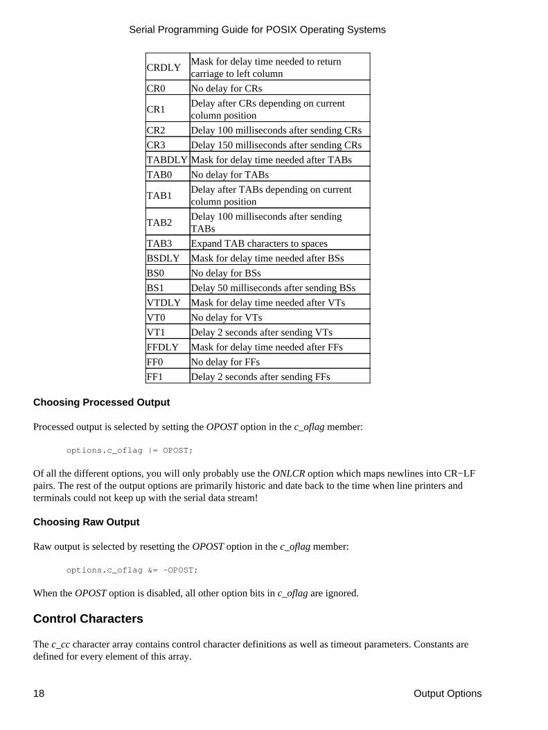
CRDLYMask for delay time needed to returncarriage to left column
CR0 No delay for CRs
CR1Delay after CRs depending on currentcolumn position
CR2 Delay 100 milliseconds after sending CRs
CR3 Delay 150 milliseconds after sending CRs
TABDLY Mask for delay time needed after TABs
TAB0 No delay for TABs
TAB1Delay after TABs depending on currentcolumn position
TAB2Delay 100 milliseconds after sendingTABs
TAB3 Expand TAB characters to spaces
BSDLY Mask for delay time needed after BSs
BS0 No delay for BSs
BS1 Delay 50 milliseconds after sending BSs
VTDLY Mask for delay time needed after VTs
VT0 No delay for VTs
VT1 Delay 2 seconds after sending VTs
FFDLY Mask for delay time needed after FFs
FF0 No delay for FFs
FF1 Delay 2 seconds after sending FFs
Choosing Processed Output
Processed output is selected by setting the OPOST option in the c_oflag member:
options.c_oflag |= OPOST;
Of all the different options, you will only probably use the ONLCR option which maps newlines into CR−LFpairs. The rest of the output options are primarily historic and date back to the time when line printers andterminals could not keep up with the serial data stream!
Choosing Raw Output
Raw output is selected by resetting the OPOST option in the c_oflag member:
options.c_oflag &= ~OPOST;
When the OPOST option is disabled, all other option bits in c_oflag are ignored.
Control Characters
The c_cc character array contains control character definitions as well as timeout parameters. Constants aredefined for every element of this array.
Serial Programming Guide for POSIX Operating Systems
18 Output Options

Table 9 − Control Characters in the c_cc Member
Constant Description Key
VINTR Interrupt CTRL−C
VQUIT Quit CTRL−Z
VERASE Erase Backspace (BS)
VKILL Kill−line CTRL−U
VEOF End−of−file CTRL−D
VEOL End−of−line Carriage return (CR)
VEOL2 Second end−of−line Line feed (LF)
VMIN Minimum number of characters to read
VTIME Time to wait for data (tenths of seconds)
Setting Software Flow Control Characters
The VSTART and VSTOP elements of the c_cc array contain the characters used for software flow control.Normally they should be set to DC1 (021 octal) and DC3 (023 octal) which represent the ASCII standardXON and XOFF characters.
Setting Read Timeouts
UNIX serial interface drivers provide the ability to specify character and packet timeouts. Two elements ofthe c_cc array are used for timeouts: VMIN and VTIME. Timeouts are ignored in canonical input mode orwhen the NDELAY option is set on the file via open or fcntl.
VMIN specifies the minimum number of characters to read. If it is set to 0, then the VTIME value specifies thetime to wait for every character read. Note that this does not mean that a read call for N bytes will wait for Ncharacters to come in. Rather, the timeout will apply to the first character and the read call will return thenumber of characters immediately available (up to the number you request).
If VMIN is non−zero, VTIME specifies the time to wait for the first character read. If a character is read withinthe time given, any read will block (wait) until all VMIN characters are read. That is, once the first character isread, the serial interface driver expects to receive an entire packet of characters (VMIN bytes total). If nocharacter is read within the time allowed, then the call to read returns 0. This method allows you to tell theserial driver you need exactly N bytes and any read call will return 0 or N bytes. However, the timeout onlyapplies to the first character read, so if for some reason the driver misses one character inside the N bytepacket then the read call could block forever waiting for additional input characters.
VTIME specifies the amount of time to wait for incoming characters in tenths of seconds. If VTIME is set to 0(the default), reads will block (wait) indefinitely unless the NDELAY option is set on the port with open orfcntl.
Serial Programming Guide for POSIX Operating Systems
Control Characters 19

Serial Programming Guide for POSIX Operating Systems
20 Control Characters
Chapter 3, MODEM Communications
This chapter covers the basics of dialup telephone Modulator/Demodulator (MODEM) communications.Examples are provided for MODEMs that use the defacto standard "AT" command set.
What Is a MODEM?
MODEMs are devices that modulate serial data into frequencies that can be transferred over an analog datalink such as a telephone line or cable TV connection. A standard telephone MODEM converts serial data intotones that can be passed over the phone lines; because of the speed and complexity of the conversion thesetones sound more like loud screeching if you listen to them.
Telephone MODEMs are available today that can transfer data across a telephone line at nearly 53,000 bitsper second, or 53kbps. In addition, most MODEMs use data compression technology that can increase the bitrate to well over 100kbps on some types of data.
Communicating With a MODEM
The first step in communicating with a MODEM is to open and configure the port for raw input:
Listing 3 − Configuring the port for raw input.
int fd;struct termios options;
/* open the port */
Chapter 3, MODEM Communications 21

fd = open("/dev/ttyf1", O_RDWR | O_NOCTTY | O_NDELAY);fcntl(fd, F_SETFL, 0);
/* get the current options */tcgetattr(fd, &options);
/* set raw input, 1 second timeout */options.c_cflag |= (CLOCAL | CREAD);options.c_lflag &= ~(ICANON | ECHO | ECHOE | ISIG);options.c_oflag &= ~OPOST;options.c_cc[VMIN] = 0;options.c_cc[VTIME] = 10;
/* set the options */tcsetattr(fd, TCSANOW, &options);
Next you need to establish communications with the MODEM. The best way to do this is by sending the "AT"command to the MODEM. This also allows smart MODEMs to detect the baud you are using. When theMODEM is connected correctly and powered on it will respond with the response "OK".
Listing 4 − Initializing the MODEM.
int /* O − 0 = MODEM ok, −1 = MODEM bad */init_modem(int fd) /* I − Serial port file */{ char buffer[255]; /* Input buffer */ char *bufptr; /* Current char in buffer */ int nbytes; /* Number of bytes read */ int tries; /* Number of tries so far */
for (tries = 0; tries < 3; tries ++) { /* send an AT command followed by a CR */ if (write(fd, "AT\r", 3) < 3) continue;
/* read characters into our string buffer until we get a CR or NL */ bufptr = buffer; while ((nbytes = read(fd, bufptr, buffer + sizeof(buffer) − bufptr − 1)) > 0) { bufptr += nbytes; if (bufptr[−1] == '\n' || bufptr[−1] == '\r') break; }
/* nul terminate the string and see if we got an OK response */ *bufptr = '\0';
if (strncmp(buffer, "OK", 2) == 0) return (0); }
return (−1);}
Standard MODEM Commands
Most MODEMs support the "AT" command set, so called because each command starts with the "AT"
Serial Programming Guide for POSIX Operating Systems
22 Standard MODEM Commands
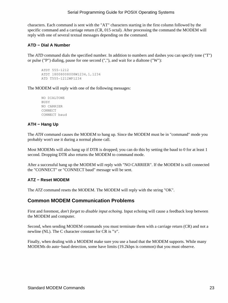
characters. Each command is sent with the "AT" characters starting in the first column followed by thespecific command and a carriage return (CR, 015 octal). After processing the command the MODEM willreply with one of several textual messages depending on the command.
ATD − Dial A Number
The ATD command dials the specified number. In addition to numbers and dashes you can specify tone ("T")or pulse ("P") dialing, pause for one second (","), and wait for a dialtone ("W"):
ATDT 555−1212ATDT 18008008008W1234,1,1234ATD T555−1212WP1234
The MODEM will reply with one of the following messages:
NO DIALTONEBUSYNO CARRIERCONNECTCONNECT baud
ATH − Hang Up
The ATH command causes the MODEM to hang up. Since the MODEM must be in "command" mode youprobably won't use it during a normal phone call.
Most MODEMs will also hang up if DTR is dropped; you can do this by setting the baud to 0 for at least 1second. Dropping DTR also returns the MODEM to command mode.
After a successful hang up the MODEM will reply with "NO CARRIER". If the MODEM is still connectedthe "CONNECT" or "CONNECT baud" message will be sent.
ATZ − Reset MODEM
The ATZ command resets the MODEM. The MODEM will reply with the string "OK".
Common MODEM Communication Problems
First and foremost, don't forget to disable input echoing. Input echoing will cause a feedback loop betweenthe MODEM and computer.
Second, when sending MODEM commands you must terminate them with a carriage return (CR) and not anewline (NL). The C character constant for CR is "\r".
Finally, when dealing with a MODEM make sure you use a baud that the MODEM supports. While manyMODEMs do auto−baud detection, some have limits (19.2kbps is common) that you must observe.
Serial Programming Guide for POSIX Operating Systems
Standard MODEM Commands 23

Serial Programming Guide for POSIX Operating Systems
24 Standard MODEM Commands

Chapter 4, Advanced Serial Programming
This chapter covers advanced serial programming techniques using the ioctl(2) and select(2) system calls.
Serial Port IOCTLs
In Chapter 2, Configuring the Serial Port we used the tcgetattr and tcsetattr functions to configure the serialport. Under UNIX these functions use the ioctl(2) system call to do their magic.
The ioctl system call takes three arguments:
int ioctl(int fd, int request, ...);
The fd argument specifies the serial port file descriptor. The request argument is a constant defined in the<termios.h> header file and is typically one of the following:
Table 10 − IOCTL Requests for Serial Ports
Request Description POSIX Function
TCGETSGets the current serialport settings.
tcgetattr
TCSETSSets the serial portsettings immediately.
tcsetattr(fd, TCSANOW, &options)
TCSETSF Sets the serial portsettings after flushing
tcsetattr(fd, TCSAFLUSH, &options)
Chapter 4, Advanced Serial Programming 25

the input and outputbuffers.
TCSETSW
Sets the serial portsettings after allowingthe input and outputbuffers to drain/empty.
tcsetattr(fd, TCSADRAIN, &options)
TCSBRKSends a break for thegiven time.
tcsendbreak, tcdrain
TCXONCControls software flowcontrol.
tcflow
TCFLSHFlushes the inputand/or output queue.
tcflush
TIOCMGETReturns the state of the"MODEM" bits.
None
TIOCMSETSets the state of the"MODEM" bits.
None
FIONREADReturns the number ofbytes in the inputbuffer.
None
Getting the Control Signals
The TIOCMGET ioctl gets the current "MODEM" status bits, which consist of all of the RS−232 signal linesexcept RXD and TXD:
Table 11 − Control Signal Constants
Constant Description
TIOCM_LE DSR (data set ready/line enable)
TIOCM_DTR DTR (data terminal ready)
TIOCM_RTS RTS (request to send)
TIOCM_ST Secondary TXD (transmit)
TIOCM_SR Secondary RXD (receive)
TIOCM_CTS CTS (clear to send)
TIOCM_CAR DCD (data carrier detect)
TIOCM_CD Synonym for TIOCM_CAR
TIOCM_RNG RNG (ring)
TIOCM_RI Synonym for TIOCM_RNG
TIOCM_DSR DSR (data set ready)
To get the status bits, call ioctl with a pointer to an integer to hold the bits:
Listing 5 − Getting the MODEM status bits.
#include <unistd.h>#include <termios.h>
Serial Programming Guide for POSIX Operating Systems
26 Getting the Control Signals

int fd;int status;
ioctl(fd, TIOCMGET, &status);
Setting the Control Signals
The TIOCMSET ioctl sets the "MODEM" status bits defined above. To drop the DTR signal you can do:
Listing 6 − Dropping DTR with the TIOCMSET ioctl.
#include <unistd.h>#include <termios.h>
int fd;int status;
ioctl(fd, TIOCMGET, &status);
status &= ~TIOCM_DTR;
ioctl(fd, TIOCMSET, &status);
The bits that can be set depend on the operating system, driver, and modes in use. Consult your operatingsystem documentation for more information.
Getting the Number of Bytes Available
The FIONREAD ioctl gets the number of bytes in the serial port input buffer. As with TIOCMGET you pass ina pointer to an integer to hold the number of bytes:
Listing 7 − Getting the number of bytes in the input buffer.
#include <unistd.h>#include <termios.h>
int fd;int bytes;
ioctl(fd, FIONREAD, &bytes);
This can be useful when polling a serial port for data, as your program can determine the number of bytes inthe input buffer before attempting a read.
Selecting Input from a Serial Port
While simple applications can poll or wait on data coming from the serial port, most applications are notsimple and need to handle input from multiple sources.
UNIX provides this capability through the select(2) system call. This system call allows your program tocheck for input, output, or error conditions on one or more file descriptors. The file descriptors can point toserial ports, regular files, other devices, pipes, or sockets. You can poll to check for pending input, wait forinput indefinitely, or timeout after a specific amount of time, making the select system call extremely flexible.
Serial Programming Guide for POSIX Operating Systems
Setting the Control Signals 27

Most GUI Toolkits provide an interface to select; we will discuss the X Intrinsics ("Xt") library later in thischapter.
The SELECT System Call
The select system call accepts 5 arguments:
int select(int max_fd, fd_set *input, fd_set *output, fd_set *error, struct timeval *timeout);
The max_fd argument specifies the highest numbered file descriptor in the input, output, and error sets. Theinput, output, and error arguments specify sets of file descriptors for pending input, output, or errorconditions; specify NULL to disable monitoring for the corresponding condition. These sets are initializedusing three macros:
FD_ZERO(fd_set);FD_SET(fd, fd_set);FD_CLR(fd, fd_set);
The FD_ZERO macro clears the set entirely. The FD_SET and FD_CLR macros add and remove a filedescriptor from the set, respectively.
The timeout argument specifies a timeout value which consists of seconds (timeout.tv_sec) and microseconds(timeout.tv_usec). To poll one or more file descriptors, set the seconds and microseconds to zero. To waitindefinitely specify NULL for the timeout pointer.
The select system call returns the number of file descriptors that have a pending condition, or −1 if there wasan error.
Using the SELECT System Call
Suppose we are reading data from a serial port and a socket. We want to check for input from either filedescriptor, but want to notify the user if no data is seen within 10 seconds. To do this we'll need to use theselect system call:
Serial Programming Guide for POSIX Operating Systems
28 The SELECT System Call
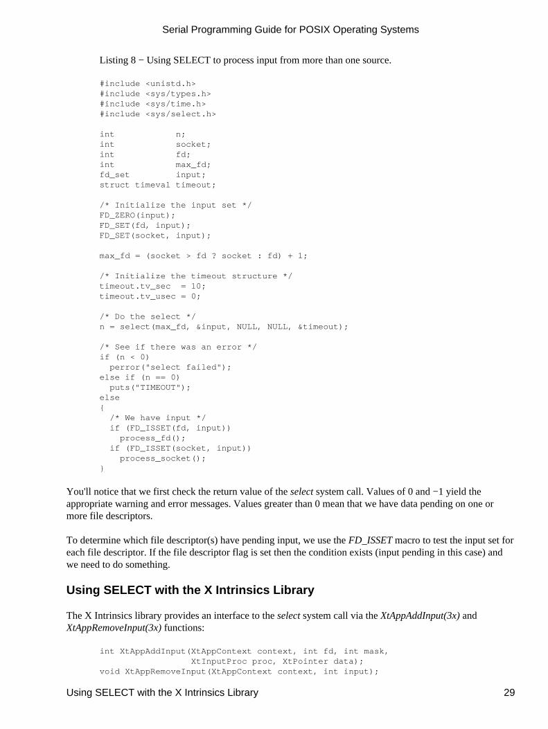
Listing 8 − Using SELECT to process input from more than one source.
#include <unistd.h>#include <sys/types.h>#include <sys/time.h>#include <sys/select.h>
int n;int socket;int fd;int max_fd;fd_set input;struct timeval timeout;
/* Initialize the input set */FD_ZERO(input);FD_SET(fd, input);FD_SET(socket, input);
max_fd = (socket > fd ? socket : fd) + 1;
/* Initialize the timeout structure */timeout.tv_sec = 10;timeout.tv_usec = 0;
/* Do the select */n = select(max_fd, &input, NULL, NULL, &timeout);
/* See if there was an error */if (n < 0) perror("select failed");else if (n == 0) puts("TIMEOUT");else{ /* We have input */ if (FD_ISSET(fd, input)) process_fd(); if (FD_ISSET(socket, input)) process_socket();}
You'll notice that we first check the return value of the select system call. Values of 0 and −1 yield theappropriate warning and error messages. Values greater than 0 mean that we have data pending on one ormore file descriptors.
To determine which file descriptor(s) have pending input, we use the FD_ISSET macro to test the input set foreach file descriptor. If the file descriptor flag is set then the condition exists (input pending in this case) andwe need to do something.
Using SELECT with the X Intrinsics Library
The X Intrinsics library provides an interface to the select system call via the XtAppAddInput(3x) andXtAppRemoveInput(3x) functions:
int XtAppAddInput(XtAppContext context, int fd, int mask, XtInputProc proc, XtPointer data);void XtAppRemoveInput(XtAppContext context, int input);
Serial Programming Guide for POSIX Operating Systems
Using SELECT with the X Intrinsics Library 29
The select system call is used internally to implement timeouts, work procedures, and check for input from theX server. These functions can be used with any Xt−based toolkit including Xaw, Lesstif, and Motif.
The proc argument to XtAppAddInput specifies the function to call when the selected condition (e.g. inputavailable) exists on the file descriptor. In the previous example you could specify the process_fd orprocess_socket functions.
Because Xt limits your access to the select system call, you'll need to implement timeouts through anothermechanism, probably via XtAppAddTimeout(3x).
Serial Programming Guide for POSIX Operating Systems
30 Using SELECT with the X Intrinsics Library

Appendix A, Pinouts
This appendix provides pinout information for many of the common serial ports you will find.
RS−232 Pinouts
RS−232 comes in three flavors (A, B, C) and uses a 25−pin D−Sub connector:
Figure 2 − RS−232 Connector
Table 12 − RS−232 Signals
Pin Description Pin Description
1 Earth Ground 14 Secondary TXD
2 TXD − Transmitted Data 15 Transmit Clock
3 RXD − Received Data 16 Secondary RXD
4 RTS − Request To Send 17 Receiver Clock
5 CTS − Clear To Send 18 Unassigned
6 DSR − Data Set Ready 19 Secondary RTS
Appendix A, Pinouts 31

7 GND − Logic Ground 20 DTR − Data Terminal Ready
8 DCD − Data Carrier Detect21 Signal Quality Detect
9 Reserved 22 Ring Detect
10 Reserved 23 Data Rate Select
11 Unassigned 24 Transmit Clock
12 Secondary DCD 25 Unassigned
13 Secondary CTS
RS−422 Pinouts
RS−422 also uses a 25−pin D−Sub connector, but with differential signals:
Figure 3 − RS−422 Connector
Table 13 − RS−422 Signals
Pin Description Pin Description
1 Earth Ground 14 TXD+
2 TXD− − Transmitted Data 15 Transmit Clock−
3 RXD− − Received Data 16 RXD+
4 RTS− − Request To Send 17 Receiver Clock−
5 CTS− − Clear To Send 18 Unassigned
6 DSR − Data Set Ready 19 RTS+
7 GND − Logic Ground 20 DTR− − Data Terminal Ready
8 DCD− − Data Carrier Detect21 Signal Quality Detect
9 Reserved 22 Unassigned
10 Reserved 23 DTR+
11 Unassigned 24 Transmit Clock+
12 DCD+ 25 Receiver Clock+
13 CTS+
RS−574 (IBM PC/AT) Pinouts
The RS−574 interface is used exclusively by PC manufacturers and uses a 9−pin male D−Sub connector:
Figure 4 − RS−574 Connector
Serial Programming Guide for POSIX Operating Systems
32 RS−422 Pinouts
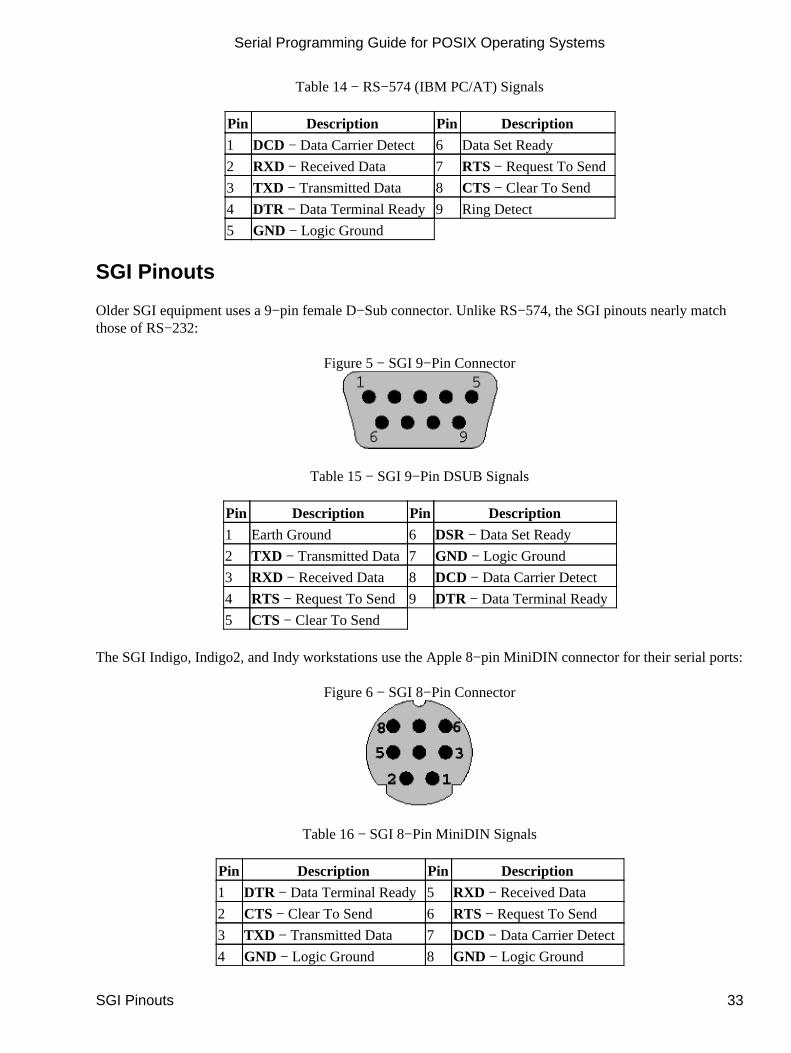
Table 14 − RS−574 (IBM PC/AT) Signals
Pin Description Pin Description
1 DCD − Data Carrier Detect 6 Data Set Ready
2 RXD − Received Data 7 RTS − Request To Send
3 TXD − Transmitted Data 8 CTS − Clear To Send
4 DTR − Data Terminal Ready9 Ring Detect
5 GND − Logic Ground
SGI Pinouts
Older SGI equipment uses a 9−pin female D−Sub connector. Unlike RS−574, the SGI pinouts nearly matchthose of RS−232:
Figure 5 − SGI 9−Pin Connector
Table 15 − SGI 9−Pin DSUB Signals
Pin Description Pin Description
1 Earth Ground 6 DSR − Data Set Ready
2 TXD − Transmitted Data7 GND − Logic Ground
3 RXD − Received Data 8 DCD − Data Carrier Detect
4 RTS − Request To Send9 DTR − Data Terminal Ready
5 CTS − Clear To Send
The SGI Indigo, Indigo2, and Indy workstations use the Apple 8−pin MiniDIN connector for their serial ports:
Figure 6 − SGI 8−Pin Connector
Table 16 − SGI 8−Pin MiniDIN Signals
Pin Description Pin Description
1 DTR − Data Terminal Ready5 RXD − Received Data
2 CTS − Clear To Send 6 RTS − Request To Send
3 TXD − Transmitted Data 7 DCD − Data Carrier Detect
4 GND − Logic Ground 8 GND − Logic Ground
Serial Programming Guide for POSIX Operating Systems
SGI Pinouts 33

Serial Programming Guide for POSIX Operating Systems
34 SGI Pinouts
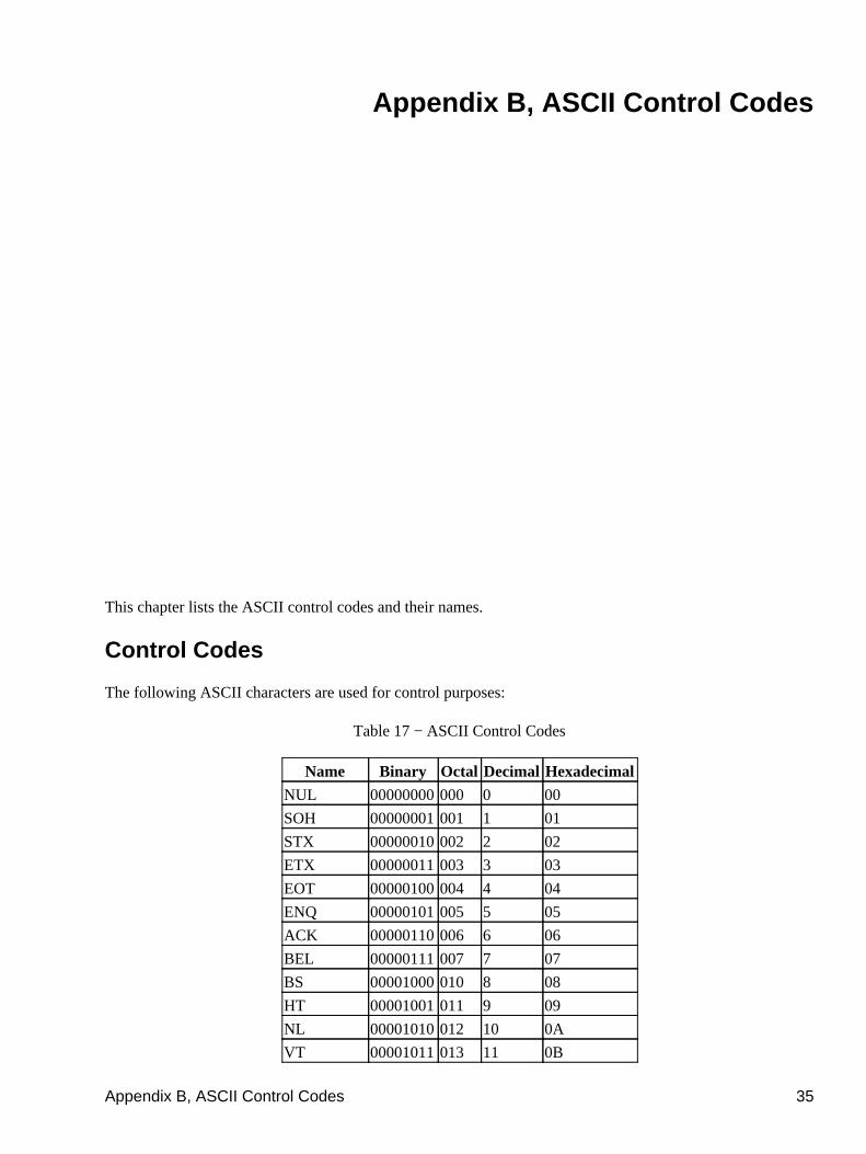
Appendix B, ASCII Control Codes
This chapter lists the ASCII control codes and their names.
Control Codes
The following ASCII characters are used for control purposes:
Table 17 − ASCII Control Codes
Name Binary Octal Decimal Hexadecimal
NUL 00000000000 0 00
SOH 00000001001 1 01
STX 00000010002 2 02
ETX 00000011003 3 03
EOT 00000100004 4 04
ENQ 00000101005 5 05
ACK 00000110006 6 06
BEL 00000111007 7 07
BS 00001000010 8 08
HT 00001001011 9 09
NL 00001010012 10 0A
VT 00001011013 11 0B
Appendix B, ASCII Control Codes 35

NP, FF 00001100014 12 0C
CR 00001101015 13 0D
SO 00001110016 14 0E
SI 00001111017 15 0F
DLE 00010000020 16 10
XON, DC1 00010001021 17 11
DC2 00010010022 18 12
XOFF, DC3 00010011023 19 13
DC4 00010100024 20 14
NAK 00010101025 21 15
SYN 00010110026 22 16
ETB 00010111027 23 17
CAN 00011000030 24 18
EM 00011001031 25 19
SUB 00011010032 26 1A
ESC 00011011033 27 1B
FS 00011100034 28 1C
GS 00011101035 29 1D
RS 00011110036 30 1E
US 00011111037 31 1F
Serial Programming Guide for POSIX Operating Systems
36 Appendix B, ASCII Control Codes