Embed Size (px)
Citation preview

www.bnd.com.au
Series 1 - Installation instructions (including Windlock option)
Standard Series 1 profile(R1D, R1M, R1P)
New Series 1 NEO profile(R1N)
These instructions are intended for professional garage door installers. All references are taken from inside looking out.
DOC# 165100_11PART NO# 007488RELEASED: 21/09/21

contents
1.0 before you begin 3
1.1 installation safety warnings 3
1.2 substrate fastener recommendations 4
1.3 requirements before installation 5
1.3.1 measurements 5
1.3.2 measurements continued 6
1.4 tools 7
1.5 parts checklist 7
1.6 initial calculations 7
2.0 installation 8
2.1 install first bracket 8
2.2 install second bracket 8
2.3 place door on brackets 9
2.4 position door 9
2.5 tension the springs 10
2.6 notching bottom rail (only for high wind doors) 10
2.7 attaching stop 10
2.8 guides 11
2.9 troubleshooting 13
2.10 centralise the axle when door is mounted 13
2.11 to adjust spring tension 14
3.0 appendix 15
3.1 fixing alternatives 15
3.2 centre lift handle 15
3.3 fitting plastic lift handle 16
3.4 fitting metal lift handle (R1M only) 16
3.5 centre lift lock 17
3.6 additional locks (R1M) 18
3.7 after installation care 19
2Roll-A-Door® Series 1 - installation instructions

1.1 installation safety warnings
WARNING! Crush injury from unsecured door
• Place a 2 metre exclusion zone around area under the garage opening while installing door. If sufficient area is not available DO NOT install door.
• Do not move under a door while it is on the door support (or lifting device).• Follow the installation instructions.• Fit door support (or lifting device) snugly under door before lifting.• Ensure door support (or lifting device) is on flat ground.• Ensure the door is immediately fastened to the bracket with the "U" Bolt.• Ensure no-one walks under a door sitting on brackets.
Tension Springs • Ensure door is correctly secured at all times when making adjustments.• Ensure the correct length pipe wrench is utilised.• Ensure that pipe wrench is fitted correctly to the axle and if it is gripped onto
the axle do not underestimate the tension in the spring when undoing the clamps.
• Ensure correct bolts are tightened or loosened to ensure there is no release or controlled release of energy from the spring through the pipe wrench.
• Keep head clear of the pipe wrench at all times.
ELECTROCUTION! • Check risk assessment for any highlighted electrical power concerns.• Ensure power source is isolated prior to commencement of job.• Turn off electricity to site when necessary.• Wear rubber soled footwear.
LACERATION: • Wear appropriate PPE (Dyneema cut off gloves) and keep hands well clear of pinch points.
• Follow instructions explicitly, particularly for the installation of some parts of the doors, as the unrolled cut out edges presents a very sharp edge.
CAUTION:Muscular strain • Practice correct lifting techniques when required to lift the door.
• Use mechanical aids such as lifting devices, forklift and cranes where possible.
• Avoid twisting.• Use correct technique of knotted rope installation aids.
Fall from ladder • Ensure ladder is the correct type for job.• Ensure ladder is on flat firm ground that will take the weight without the legs
sinking.• Ensure user has 3 points of contact while on ladder.
Hand Tools • Wear appropriate PPE and utilise operators manual of all tools.• Use appropriate noise/hearing protection in the form of ear plugs or ear
muffs.• Ensure appropriate fire protection available and housekeeping to ensure
that flammable liquids or materials are removed from the area of work.
Entanglement • Keep hands and loose clothing clear of moving door and guides at all times.
TWO PERSON LIFT: • When a mechanical aid is not used this product requires a two person lift to raise onto the brackets. Use proper techniques and equipment to lift the door from the trailer and up onto brackets.
This B&D Roll-A-Door is designed and tested to provide security, attractive appearance and smooth , low effort operation provided it is installed and operated in strict accordance with the following safety warnings. Failure to comply with the following instructions may result in death, serious personal injury or property damage.
NOTE: No guarantee will be given or responsibility accepted by the manufacturers if the door is not installed as instructed.
1.0 before you begin
3Roll-A-Door® Series 1 - installation instructions

1.2 substrate fastener recommendations
long bolts
steel plate
left hand bracket
masonry anchors (minimum bolt size 5/16” x 50mm long)
BRICK CONSTRUCTION
bolt guides to steel
work
MASONARY BLOCK CONSTRUCTION
STEEL CONSTRUCTION
WARNING! Masonary blockwork should be properly filled and reinforced if brackets are to be mounted directly to blockwork with masonry anchors. Where the blockwork is not solidly filled but structurally sound, long bolts should be passed through the blockwork using suitable steel plates under bolt heads. Special consideration should be given to brick type and construction of wall, to ensure satisfactory fixing.
bolts & washers
nuts
WARNING! The installer must select and use fasteners appropriate to the material into which they are being fixed.
important notes
a) For installation to materials not covered in the chart, the installer should seek expert advice from a qualified builder.
b) Minimum length of fastener does not exclude use of longer lengths. Decision must be made by fitter to ensure adequate strength.
c) Recommendations for old materials or materials not in good condition are not included. If in doubt about the strength of the material seek specialist advice.
d) Fasteners for brackets in masonry should be at least 5/16” x 2.5” long or metric equivalent.
e) Use the washers supplied in the parts bag to all fixings.
material fastener type(s) diameter or type
length of fastener
(see note)BKT GUIDE
New Solid Brick
Coach Bolts (Hex Lag Screw) and washers - combined with wall plugs
5/16” x 1½” •
3/8” x 2” • •
Macplugs (wall plugs) to suit above5/16” x 50mm •
3/8” x 60mm • •
HLC Sleeve Anchors (Dyna Bolts) with washers 12mm x 55mm •
New Hollow Brick HRD-VGK or HGK-VGS (Hex Head) Frame Anchors with washers 10mm x 60mm • •
New Solid Concrete
Coach Bolts (Hex Lag Screw) and washers - combined with wall plugs
5/16” x 1½” •
3/8” x 2” • •
Macplugs (wall plugs) to suit above5/16” x 50mm •
3/8” x 60mm • •
HLC Sleeve Anchors (Dyna Bolts) with washers 12mm x 55mm •
Steel Framing e.g. BHP Framing
(with rear access)
Hex Head Bolt Zinc Plated, Hexagon Nuts Zinc Plated,
Washers Zinc Plated
5/16” x 1” •
3/8” x 1” • •
10mm x 25mm • •
12mm x 25mm •
Heavy Gauge Steel Hex Head Tek and washers 14-20 x 22mm • •
Light Steel Framing e.g. BHP House
Framing (no rear access)
Heavy Duty Kap Toggle10mm x 100mm • •
12mm x 100mm •
Hex Head Tek and washers 6-10 x 20mm •
New TimberCoach Bolts (Hex Lag Screw) and
washers5/16” x 1½” •
3/8” x 2” • •
Hex Head Tek and washers 14-10 x 50mm • •
WARNING! Coach bolts/screws are NOT suitable for windrated doors. Refer to High Wind drawings on the B&D Website for Region A&B or Region C.
4Roll-A-Door® Series 1 - installation instructions
mounting - The door is designed to be mounted behind the opening.
obstructions - Ensure that the surface where the door will be fitted is flush and smooth, and the area behind the opening is free from any protrusions.
structural suitability - Ensure the opening is strong enough to support the door. If unsure, consult a builder.
level and plumb - The door must be installed in an absolutely level position, if opening is not level and square, appearance and/or sideroom requirements will be affected. The floor should be level or recessed across the opening to avoid gaps.
1.3 requirements before installation
LINTEL HEIGHT
OPENINGWIDTH
SID
ERO
OM
BACKROOM
HEADROOM
SID
ERO
OM
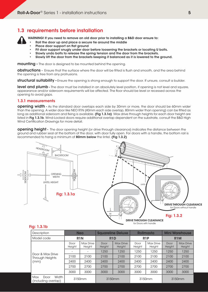
1.3.1 measurementsopening width - As the standard door overlaps each side by 30mm or more, the door should be 60mm wider than the opening. A wider door like NEO R1N (40mm each side overlap, 80mm wider than opening) can be fitted as long as additional sideroom and fixing is available. (Fig 1.3.1a) Max drive through heights for each door height are listed in Fig 1.3.1b. Wind-Locked doors require additional overlap dependent on the substrate, consult the B&D High Wind Certification Drawings for more detail.
opening height - The door opening height (or drive through clearance) indicates the distance between the ground and rubber seal at the bottom of the door, with door fully open. For doors with a handle, the bottom rail is recommended to hang a minimum of 80mm below the lintel. (Fig 1.3.2)
LINTEL HEIGHTDRIVE THROUGH
CLEARANCE
Fig: 1.3.1a
Fig: 1.3.2
WARNING! If you need to remove an old door prior to installing a B&D door ensure to:• Roll the door up and place a secure tie around the middle• Place door support on flat ground• Fit door support snugly under door before loosening the brackets or locating U bolts.• Slowly undo bolts to release the spring tension and the door from the brackets.• Slowly lift the door from the brackets keeping it balanced as it is lowered to the ground.
Description Neo Squareline Deluxe Rollmasta Mini WarehouseModel code R1N R1D R1P R1M
Door & Max Drive Through Heights (mm)
Door Height
Max Drive Height
Door Height
Max Drive Height
Door Height
Max Drive Height
Door Height
Max Drive Height
- - 1250 1250 1250 1250 1250 1250
2100 2100 2100 2100 2100 2100 2100 2100
2400 2400 2400 2400 2400 2400 2400 2400
2700 2700 2700 2700 2700 2700 2700 2700
3000 3000 3000 3000 3000 3000 3000 3000
Max Door Width (including overlap) 3150mm 3150mm 3150mm 3150mm
80
DRIVE THROUGH CLEARANCE for Doors with handle
DRIVE THROUGH CLEARANCE for Doors without handle
Fig: 1.3.1b
5Roll-A-Door® Series 1 - installation instructions

Fig: 1.3.2a
1.3.2 measurements continued
Fig: 1.3.2d
headroom - Refer to Fig 1.3.2a and 1.3.2d for measurements for doors with and without handles. If the door is installed lower into the opening than shown in Fig 1.3.2a additional loss of door opening height will result.
dimension panel
installation height (mm)
width (mm) A* B C
DE F G H
D1 D2*
Recommendedup to 2400 up to 3150 185 185 430 440 480 230 200 0
302401-3000 up to 3150 185 185 450 460 500 250 200 0
Restrictedup to 2400 up to 3150 115 85 395 440 480 230 165 352401-3000 up to 3150 115 85 415 460 500 250 165 35
R1N Onlyup to 2400 up to 3150
195 195 450 440 500 250 200 0
40125 95 415 460 500 250 165 35
2401-3000 up to 3150195 195 470 440 590 270 200 0125 110 435 460 590 270 165 35
Windlockedup to 2400 up to 3150
185 185 430 440 480 230 200 0
55+160 130 450 460 500 250 200 35
2401-3000 up to 3150185 185 450 460 500 250 200 0160 130 450 460 500 250 200 35
*A Based on a Controll-A-Door PowerDrive. NOTE: R1N Doors over 2400mm (H) have larger bracket. Windlock option not available on all R1N doors.
NOTE: Wind-Locked doors may need between 55 - 68mm curtain overlap on both sides, depending on the substrate used.
D1 & D2* are the minimum measurements and optimum backroom clearance required for installation.
C
E
D1
F
D2
G
RECOMMENDED SIDEROOMRequired for door & opener
RESTRICTED SIDEROOMRequired for door & opener
Fig: 1.3.2b
OPENINGWIDTH
LINTEL
OPENINGWIDTH
LINTEL
Fig: 1.3.2c
CAUTION: NEO (R1D) Doors cannot be installed with removable mullions.
sideroom- is required on each side over opening width and should extend above the lintel to allow for bracket fixing. Refer to Fig 1.3.2b - 1.3.2d for sideroom required to install door with or without an opener. Opener can be installed either left or right hand side.
A ABB
HHHH
6Roll-A-Door® Series 1 - installation instructions

1.5 parts checklist
1.6 initial calculations
A B
C
D
Q RO
S
U V
F
I J KE
H HG G
T
W
L M N
P
XYZAAABFig: 1.5.1
a) Measure the opening width of garage.
b) Measure the door curtain width.
c) Calculate over lap for each side: door width - opening width : 2 = over lap
d) Mark the line for the edge of door curtain (over lap) on each side of the opening.
tip • Standard Series 1 doors = 30mm (minimum) overlap each side
• NEO Series 1 doors = 40mm (minimum) overlap each side
• Windlock (HW) Series 1 doors = 55+mm (minimum) overlap each side
SERIES 1 ROLL-A-DOOR R1D, R1P
R1M, R1N
HW
ITEM DESCRIPTION QTY QTY QTY
A ROLLED PLASTIC WRAPPED DOOR 1 1 1
B "A" STYLE BRACKETS, LEFT AND RIGHT HANDED 2 2 2
C DOORS GUIDES LEFT AND RIGHT HANDED 2 2 2
D STEEL LOCKING BARS (IF SELECTED) 2 - 2
SMALL PARTS BAG
E GUIDE CLIPS 6 6 0
F BOTTOM RAIL STOPS AND 6MM SCREWS 2 2 2
G "U" BOLTS 2 2 2
H AXLE / BRACKET SADDLES 2 2 2
I 8MM NUTS FOR "U" BOLTS 4 4 4
J 10MM WASHERS 4 4 4
K 8MM WASHERS 10 10 10
STEEL FIX PARTS BAG ADDS
L TEK SCREWS 14G - 20MM X 25MM 14 14 14
M 3/8 X 1 HEX SET SCREW FOR BRACKETS 4 4 4
N 3/8 HEX NUT FOR BRACKETS 4 4 4
SERIES 1 ROLL-A-DOOR R1D, R1P
R1M, R1N
HW
ITEM DESCRIPTION QTY QTY QTY
LOCK BAG (IF SELECTED)
O RUBBER GROMMETS 2 - 2
P COUNTER SUNK SCREWS 2 - 2
Q LOCKING BAR RETAINER 2 - 2
R LOCKING BAR COVERS 2 - 2
S 7MM X 4MM MUSHROOM HEAD SCREWS 2 - 2
T FACEPLATE AND LOCK ASSEMBLY 2-KEYS 1 - 1
CENTRE LIFT HANDLE BAG (IF SELECTED)
U CENTRE LIFT HANDLE W/ BACKING PLATE 1 - 1
V FACEPLATE WITH NAME INSERT 1 - 1
W M5 X 12 CSK SCREW 2 - 2
STEEL HANDLE PARTS BAG (R1M ONLY)
X HANDLE "D" PRESSED METAL - 1 -
Y 1/4 X 1/2 MS COACH BOLT & FLANGE NUT - 2 -
Z ROPE PULL LONG LFT 6MM X 900MM - 1 -
PLASTIC HANDLE PARTS BAG (IF SELECTED)
AA HANDLE PLASTIC 1 - -
AB COUNTER SUNK SCREWS, WASHERS & NUTS 2 - -
1.4 toolsA professional installers tool kit is required to install the door. You will need assistance to help you lift the door up safely and carry out some other steps.
A Soft Wood Chock will help hold the door until the guides and stops are fitted. Prepare a 400mm long Wood Chock as per diagram Figure 1.4.1.
roll-a-guide
spaceevenly
200mm
bottom rail
bottom rail lip
stop
1
wood chock
200mm
Fig: 1.4.1
7Roll-A-Door® Series 1 - installation instructions

2.0 installation2.1 install first bracket
a) Use above diagram and table Fig 2.1.1 for head and sideroom clearances.
b) Mark two hole positions using top and bottom slots of the bracket B .
c) Drill both holes, then attach bracket using large diameter washers with 2x100xM10 Anchor screws or equivalent.
d) For fixing to steel jamb, drill two holes and fix bracket with 2 x hex set screws M with large washers J and nuts N if accessible for nuts. Otherwise use 3 x Teks Screws L and 3 x small washers K .
2.2 install second bracket
centering axle
(a)
(b)
BOTTOM RAIL AT 3 O’CLOCK
axle “floats” ineither direction
EQUAL
WATER LEVEL
EQUAL
HOSE
a) Using a laser or water level, mark the position for the second bracket (Fig 2.2.1)
b) Re-check levels then drill and fix as with first bracket.
E
A OR B
C
F
CAUTION: The brackets must be perfectly level for the door to operate.
B
Fig: 2.1.1
Fig: 2.2.1
WARNING! The installer must select and use fasteners appropriate to the material into which they are being fixed. Refer to Section 1.2 for recommendations.
dimension panel
installation height (mm)
width (mm) A* B C E F
Recommendedup to 2400 up to 3150 185 185 430 230 2002401-3000 up to 3150 185 185 450 250 200
Restrictedup to 2400 up to 3150 115 85 395 230 1652401-3000 up to 3150 115 85 415 250 165
R1N Onlyup to 2400 up to 3150
195 195 450 250 200125 95 415 250 165
2401-3000 up to 3150195 195 470 270 200125 110 435 270 165
Windlockedup to 2400 up to 3150
185 185 430 230 200160 130 450 250 200
2401-3000 up to 3150185 185 450 250 200160 130 450 250 200
*A Based on a Controll-A-Door PowerDrive Opener. NOTE: Doors over 2400mm (have larger bracket)
tipTake note of drive through clearance heights in fig 1.4.2b as the bottom rail will hang into the opening on some doors, therefore reducing the opening.
WARNING! The structure substrate must conform to High Wind compliance. Refer to bac.nt.gov.au for the DTCM Manual or B&D High Wind drawings for Region A&B or Region C.
8Roll-A-Door® Series 1 - installation instructions

BOTTOM RAIL AT 3 O’CLOCK
EQUAL
WATER LEVEL
EQUAL
HOSE
centering axle
axle “�oats” ineither direction
WARNING! practice correct lifting techniques
2.3 place door on brackets
a) Check the axle length and cut if sideroom is limited. Before cutting, make sure the floating axle is free and centred (Fig 2.3.1). Centre will be found by rotating the axle a quarter turn in either direction then releasing . With centre found, make a clear mark on the axle against the hub for later reference.
b) Lift door A onto the brackets (the right way round so that the door will roll down from the front of the opening). Immediately loosely fit the “U” bolts G , saddles H , 2 x washers K and nuts I to each bracket in position shown (Fig 2.3.2). Fitting the ‘U’ bolts eliminates the door falling from the brackets. (Do not tighten until Step 2.4, c)
BOTTOM RAIL AT 3 O’CLOCK
EQUAL
WATER LEVEL
EQUAL
HOSE
centering axle
axle “�oats” ineither direction
WARNING! practice correct lifting techniques
centering axle
(a)
(b)
BOTTOM RAIL AT 3 O’CLOCK
axle “floats” ineither direction
EQUAL
WATER LEVEL
EQUAL
HOSE
2.4 position door
a) Centre the door with the opening, while ensuring the floating axle is also centred with the door.
Do this by lining up previous marks with the hub, then lift both the axle and the door together until it is centred with the opening.
b) Rotate the curtain and axle so that the bottom rail of the door is positioned as shown (3 o’clock).
c) Push the axle forward in the slots (toward the opening) and tighten the nuts firmly without over-tightening. (10 Newton metres or 6.6 feet/pounds torque reading).
TWO PERSON LIFT: this product requires a two person lift to raise onto the brackets. Use proper techniques and equipment to lift the door from the trailer and up onto brackets.
G
H
I
CAUTION: DO NOT CUT THE PLASTIC WRAP OR PACKAGING YET
Fig: 2.3.1
Fig: 2.3.2
Fig: 2.4.1
A
K
WARNING! All NEO doors must be lifted by the axles to avoid damage to curtain.
9Roll-A-Door® Series 1 - installation instructions

2.7 attaching stop
To attach bottom rail stops F to bottom rail of door. (Fig 2.7.1)
a) Hook stop behind lip in rail, as shown.
roll-a-guide
spaceevenly
200mm
bottom rail
bottom rail lip
stop
1
wood chock
200mm
2.5 tension the springs
a) Ensure that the bottom rail is at the 3 o'clock position as shown in Step 2.4.
b) Ensure both “U” bolts are tightened, then -
1. Rotate the door 1½ turns in a forward direction to apply tension. Do not let go as the springs are now tensioned. See arrow in Fig 2.5.1.
2. Hold the door firmly, NOW cut the plastic wrap along the bottom rail (taking care not to damage door surface or weatherseal).
c) Pull the curtain down slowly and carefully position the wooden chock (or other appropriate stop) you made in Step 1.4, as shown in Fig 2.5.2. Take care not to damage door surface.
The chock will help hold the door until the guides and stops are fitted.
roll-a-guide
spaceevenly
200mm
bottom rail
bottom rail lip
stop
1
wood chock
200mm
2.6 notching bottom rail (only for high wind doors)
Cut out
F
Fig: 2.5.1
Fig: 2.5.2
Fig: 2.7.1
Fig: 2.6.1
LACERATION: Wear appropriate gloves as some edges of the door are very sharp.
tipStandard Guide 1st holeWindlock Guides 3rd hole
b) Secure from underneath the rail with screws F supplied. You will need to trim the weatherseal flush with the end of the bottom rail.
WA Factory Doors VIC, NSW & QLD Factory Doors
1 2 3 1 32
10Roll-A-Door® Series 1 - installation instructions

roll-a-guide
spaceevenly
200mm
bottom rail
bottom rail lip
stop
1
wood chock
200mm
a) Check that curtain overlaps equally on both sides.
b) Check that guides C are the correct length (normal or restricted), that is, level with the brackets B . (Fig 2.8.1)
c) For Series 1 Doors:(i) Slide half the number of guide clips E into each guide C . Position the bottom
clip 200mm from the floor with the rest evenly spaced along the guide. (Fig 2.8.2)
2.8 guidesC
E
E
C
Fig: 2.8.1
tip
B
WARNING! Do not grease the guides. Grease will damage the Nylofelt® running strips and affect the operation of the door.
WARNING! All High Wind installations must adhere to fixing types and centres as referenced in the DTCM Drawings or High Wind Certification Drawings for Region A&B or Region C.
G
dimension panel
installation height (mm)
width (mm) G
Recommendedup to 2400 up to 3150 02401-3000 up to 3150 0
Restrictedup to 2400 up to 3150 352401-3000 up to 3150 35
R1N Onlyup to 2400 up to 3150
035
2401-3000 up to 31500
35
Windlockedup to 2400 up to 3150
035
2401-3000 up to 31500
35
NOTE: R1N Doors over 2400mm (have larger bracket)
If securing to uneven brickwork, packers may be required behind clips, to prevent them twisting out of square; also ensure that clips are positioned on secure bricks.
(ii) Now position one guide over the edge of the door curtain. Mark and drill the top fixed guide clip and and secure using correct fixing and washers as per table in Section 1.2, allowing no more than 1-3mm clearance between the inside of the guide and plastic Roll-A-Guide.
(iii) Ensuring guide is plumb, then drill and fix remaining clips.
For Series 1 Windlock Doors:(i) If there is limited sideroom available the guide may need
to have the side cut out to accommodate. See Fig 2.8.3 for recommended and restricted sideroom with a clearance of 1-3mm to the bottom rail roller.
(ii) Now position one guide over the edge of the door curtain. Mark and drill at top guide hole and secure guide using fixing types as per High Wind Certification drawings for Region A&B, or Region C taking note of the specific spacing requirements.
(iii) Ensuring guide is plumb, drill and fix remaining holes in guide as per spacing details listed for Region A&B.
d) With the top of the 2nd guide level with the first, repeat (c) for the specific door type.
tip To prevent clips from sliding down the guide, temporarily secure them with adhesive tape.
Fig: 2.8.3
Recommended Sideroom
Restricted Sideroom
B
C
B
C
Fig: 2.8.2
tipIf an Auto-lock is being fitted to the door, this can effect the position of the bottom guide fixing clip.
WARNING! Figure G, not recommended for doors fitted with openers
11Roll-A-Door® Series 1 - installation instructions
nylofelt
guide lead in
Fig: 2.8.4
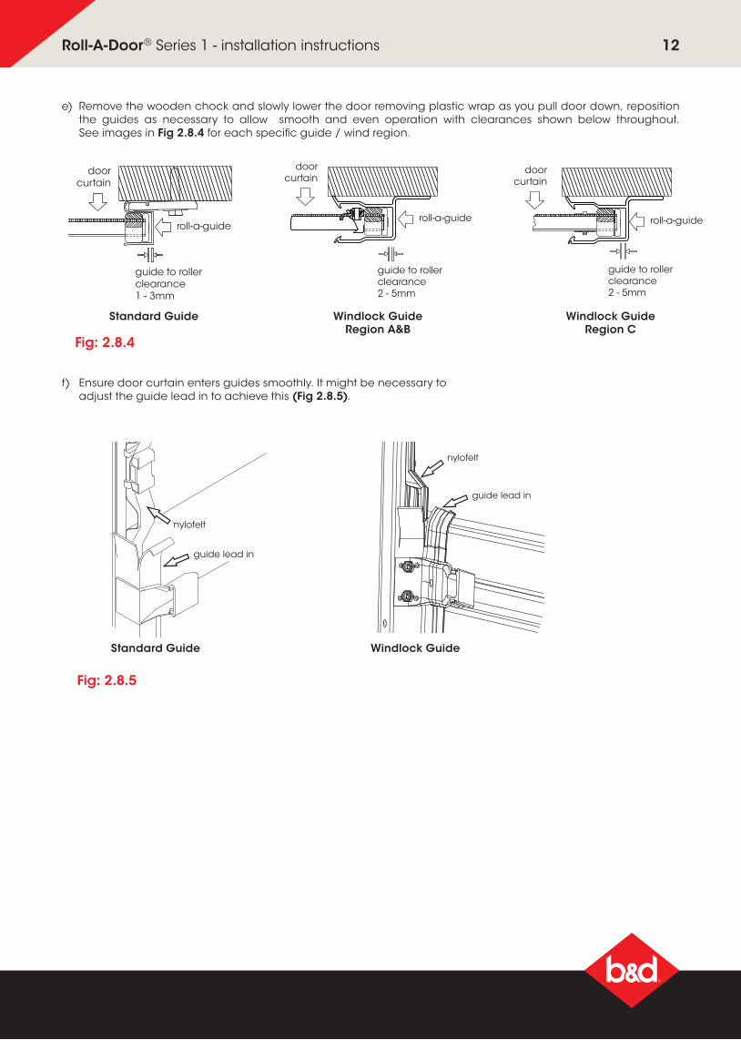
e) Remove the wooden chock and slowly lower the door removing plastic wrap as you pull door down, reposition the guides as necessary to allow smooth and even operation with clearances shown below throughout. See images in Fig 2.8.4 for each specific guide / wind region.
f) Ensure door curtain enters guides smoothly. It might be necessary to adjust the guide lead in to achieve this (Fig 2.8.5).
guide to rollerclearance1 - 3mm
roll-a-guide
doorcurtain
guide to rollerclearance2 - 5mm
roll-a-guide
doorcurtain
guide to rollerclearance2 - 5mm
roll-a-guide
doorcurtain
Standard Guide Windlock Guide Region A&B
Windlock Guide Region C
Fig: 2.8.5
Standard Guide
nylofelt
guide lead in
Windlock Guide
12Roll-A-Door® Series 1 - installation instructions

2.9 troubleshooting
“U” BOLT TO BE LOOSENED WITHOUT COMPLETELY REMOVING NUT WHILE HOLDING ONTO THE AXLE WITH A PIPE WRENCH
TO TIGHTEN SPRING TENSION
TO LOOSENSPRING TENSION
Symptom Possible cause Remedy
Door is hard to operate in ANY DIRECTION
Door jamming in the guides Check: a) the guide clearances b) the guides are plumb c) that the guide surfaces are clean and free from oil d) that the locking bars are the correct length e) that the weatherseal is correct length
The door is hard to operate in ONE DIRECTION
The spring tension requires adjustment
a) if the door is hard to lift, but tends to drop, refer to step 2.13 to increase the spring tensionb) if the door is hard to close, but tends to rise, refer to step 2.13 to decrease the spring tension
If the door rolls up crooked
Brackets are not level
Guides are not plumb
Axle is not centred
Make sure brackets are level, refer to step 2.2.
Make sure the guides are plumb, refer to step 2.8.
Centralise the axle, refer to step 2.10.
Windlock door bottom rail rubs on guides
Bottom Rail wasn't notched out Notch out bottom rail, refer to step 2.6
2.10 centralise the axle when door is mounted
WARNING! Ensure that pipe wrench is fitted correctly to the axle and if it is gripped onto the axle do not underestimate the tension in the spring when undoing the clamps.
If the door rolls up crooked with the RIGHT HAND SIDE higher than the left proceed as follows:
a) Roll the door up as high as possible and tie two ropes around the door roll approximately 300mm from each end, as a safety precaution.
b) With a person at each end of the door, hold the axle firmly with a large pip wrench (Stillson) at least 450mm long.
c) Loosen the "U" bolt nuts at both ends and KEEP A FIRM GRIP ON WRENCH.
d) Move the axle to the RIGHT between 20 - 40mm.
e) Re-tighten "U" bolts before releasing pipe wrench.
f) Test and repeat if further adjustment in needed.
g) If the door is stiff to work or rattles over lead-in on top of guide, then refer to Step 2.4.
“U” BOLT TO BE LOOSENED WITHOUT COMPLETELY REMOVING NUT WHILE HOLDING ONTO THE AXLE WITH A PIPE WRENCH
TO TIGHTEN SPRING TENSION
TO LOOSENSPRING TENSION
CAUTION: THIS ADJUSTMENT REQUIRES 2 PERSONS TO COMPLETE.
If the door rolls up crooked with the LEFT HAND SIDE higher than the left proceed as follows:
a) Roll the door up as high as possible and tie two ropes around the door roll approximately 300mm from each end, as a safety precaution.
b) With a person at each end of the door, hold the axle firmly with a large pip wrench (Stillson) at least 450mm long.
c) Loosen the "U" bolt nuts at both ends and KEEP A FIRM GRIP ON WRENCH.
d) Move the axle to the LEFT between 20 - 40mm.
e) Re-tighten "U" bolts before releasing pipe wrench.
f) Test and repeat if further adjustment in needed.
g) If the door is stiff to work or rattles over lead-in on top of guide, then refer to Step 2.4.
13Roll-A-Door® Series 1 - installation instructions
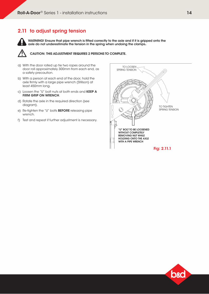
a) With the door rolled up tie two ropes around the door roll approximately 300mm from each end, as a safety precaution.
b) With a person at each end of the door, hold the axle firmly with a large pipe wrench (Stillson) at least 450mm long.
c) Loosen the “U” bolt nuts at both ends and KEEP A FIRM GRIP ON WRENCH.
d) Rotate the axle in the required direction (see diagram).
e) Re-tighten the “U” bolts BEFORE releasing pipe wrench.
f) Test and repeat if further adjustment is necessary.
“U” BOLT TO BE LOOSENED WITHOUT COMPLETELY REMOVING NUT WHILE HOLDING ONTO THE AXLE WITH A PIPE WRENCH
TO TIGHTEN SPRING TENSION
TO LOOSENSPRING TENSION
2.11 to adjust spring tension
WARNING! Ensure that pipe wrench is fitted correctly to the axle and if it is gripped onto the axle do not underestimate the tension in the spring when undoing the clamps.
CAUTION: THIS ADJUSTMENT REQUIRES 2 PERSONS TO COMPLETE.
Fig: 2.11.1
14Roll-A-Door® Series 1 - installation instructions

3.0 appendix3.1 fixing alternatives
alternative bracket fittingAn “A2”extended leg bracket should be used in conjunction with the standard “A” style bracket as shown in Fig 3.1.1.
OR
370mm
80mm
250 mm 230 mm
460 mm 460 mm
REDUCE WIDTH WITH SUITABLE TIMBER
BRICK GARAGE
NORMAL HEADROOM RESTRICTED HEADROOM
TIMBER GARAGE
(a)
(b)
(c)
COACH BOLTS
HEAVIER COACH SCREWS
“A2” EXTENDED LEG BRACKET
SECURE IF POSSIBLE
“A” BRACKET
SECURE WITH MASONRY ANCHORS
FIT HEAD INFILL PANEL
EXISTING HEAD OR LINTEL
Fig: 3.1.1
HOOK
THIS END FIRST
PLATE CORRUGATION
FACEPLAT E
BACK PLATE
3.2 centre lift handle
If the door is going to be fitted with an opener, do not install the Centre Lift Lock, any damage as a result of the manual lock will void the warranty for both door and opener. If handle is required, Centre Lift Handle can be purchased instead of lock.
The Centre Lift Handle is an option allowing to have the convenience of a waist high handle (similar to the Centre Lift Lock), but without the need to install a lock.
a) Fit faceplate V to outside of door where the hook will latch onto curtain edge, then slide faceplate as far to the right as possible. Use adhesive tape on outside to hold in position (Fig 3.2.1).
b) Attach the backplate U to the faceplate V from the inside, using the mounting screws W . Do not over tighten the screws (Fig 3.2.2).
LACERATION: Wear appropriate gloves as some edges of the door are very sharp.
U
V
V
Fig: 3.2.1 Fig: 3.2.2
NOTE: Not available for RIN.
W
15Roll-A-Door® Series 1 - installation instructions

3.3 fitting plastic lift handle (R1D only)
Fit the handle to the outside of the door using the screws, nuts and washers provided (Fig 3.3.1).
nylofelt
legs
(a)
(b)
hook
(c)
cut -
(c)
(g)
(f)
(i)
(d)
legs go under nylofelt and snap over curtain edge
lock corrugationthis end first
lock bar cover
lock bar cover
double sided adhesive tape
lock bar
lock arm
lock body
faceplate
Fig: 3.3.1
NOTE: if handle is fitted the walk through height will be reduced by 80mm.
3.4 fitting metal lift handle (R1M only)
Fit the metal handle X to the outside of the door using the screws Y , nuts and washers provided (Fig 3.4.1).
The pressed metal D handle can be fitted to any position on the exterior of the door bottom rail, it may be used as a foot plate directly below the warehouse lock.
When fitting pull cords for out of reach doors the cord Z can be threaded through the hollow section of the D handle. A knot will need to be tied and sealed at both ends.
Fig: 3.4.1NOTE: if handle is fitted the walk through height will be reduced by 80mm.
X
Y
AA
AB
16Roll-A-Door® Series 1 - installation instructions
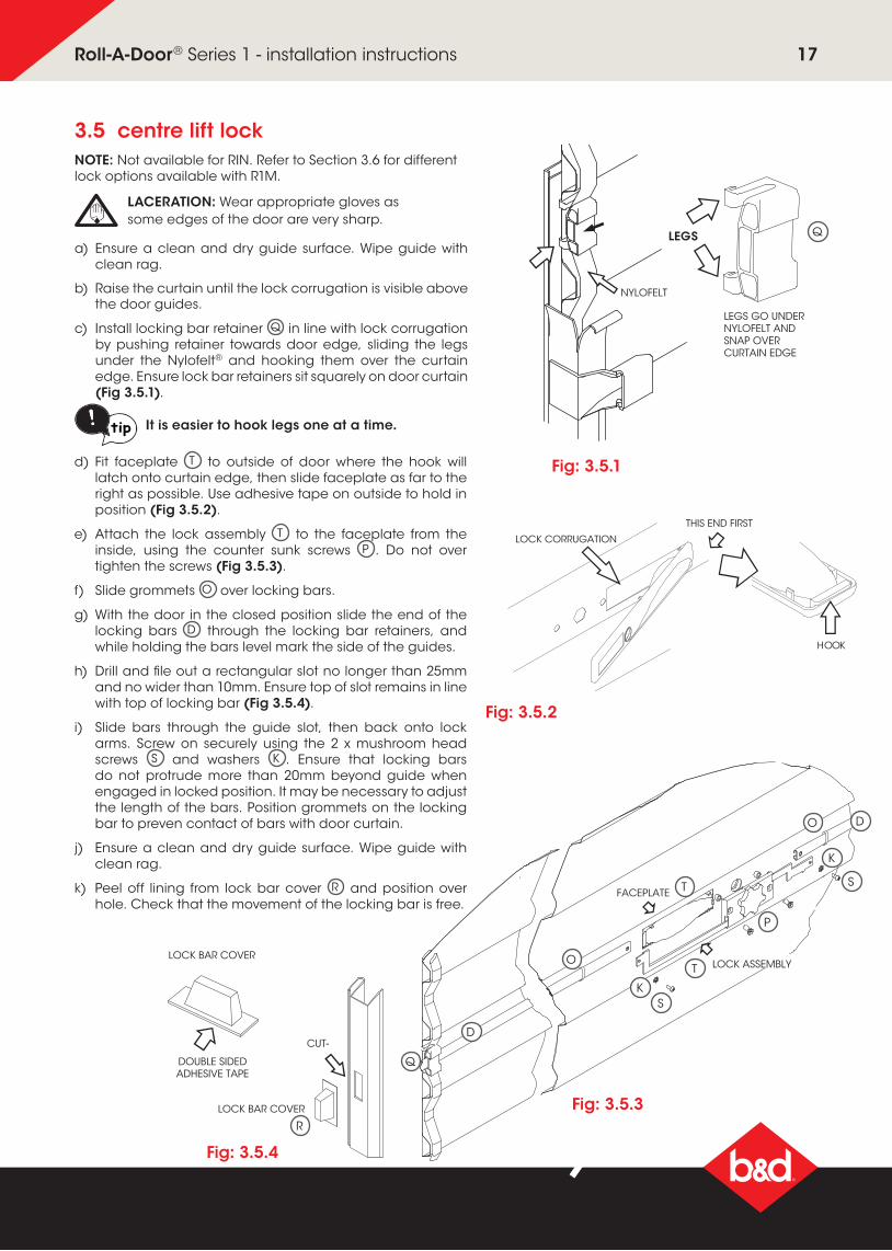
3.5 centre lift lock
a) Ensure a clean and dry guide surface. Wipe guide with clean rag.
b) Raise the curtain until the lock corrugation is visible above the door guides.
c) Install locking bar retainer Q in line with lock corrugation by pushing retainer towards door edge, sliding the legs under the Nylofelt® and hooking them over the curtain edge. Ensure lock bar retainers sit squarely on door curtain (Fig 3.5.1).
NYLOFELT
LEGS
LOCK BAR COVER
LOCK BAR COVER
CUT-
DOUBLE SIDED ADHESIVE TAPE
FACEPLATE
THIS END FIRST
HOOK
LOCK CORRUGATION
LEGS GO UNDERNYLOFELT AND SNAP OVER CURTAIN EDGE
LOCK ASSEMBLY
LACERATION: Wear appropriate gloves as some edges of the door are very sharp.
Q
Fig: 3.5.1
NOTE: Not available for RIN. Refer to Section 3.6 for different lock options available with R1M.
NYLOFELT
LEGS
LOCK BAR COVER
LOCK BAR COVER
CUT-
DOUBLE SIDED ADHESIVE TAPE
FACEPLATE
THIS END FIRST
HOOK
LOCK CORRUGATION
LEGS GO UNDERNYLOFELT AND SNAP OVER CURTAIN EDGE
LOCK ASSEMBLY
It is easier to hook legs one at a time.
d) Fit faceplate T to outside of door where the hook will latch onto curtain edge, then slide faceplate as far to the right as possible. Use adhesive tape on outside to hold in position (Fig 3.5.2).
e) Attach the lock assembly T to the faceplate from the inside, using the counter sunk screws P . Do not over tighten the screws (Fig 3.5.3).
f) Slide grommets O over locking bars.
g) With the door in the closed position slide the end of the locking bars D through the locking bar retainers, and while holding the bars level mark the side of the guides.
h) Drill and file out a rectangular slot no longer than 25mm and no wider than 10mm. Ensure top of slot remains in line with top of locking bar (Fig 3.5.4).
i) Slide bars through the guide slot, then back onto lock arms. Screw on securely using the 2 x mushroom head screws S and washers K . Ensure that locking bars do not protrude more than 20mm beyond guide when engaged in locked position. It may be necessary to adjust the length of the bars. Position grommets on the locking bar to preven contact of bars with door curtain.
j) Ensure a clean and dry guide surface. Wipe guide with clean rag.
k) Peel off lining from lock bar cover R and position over hole. Check that the movement of the locking bar is free.
HOOK
THIS END FIRST
LOCK CORRUGATION
FACEPLAT E
LOCK ASSEMBLY
WARNING! Locking bar covers must be installed to prevent possible finger entrapment.
T
T
Fig: 3.5.2
Fig: 3.5.3
Fig: 3.5.4
R
P
tip
D
Q
SK
K
S
O
O D
17Roll-A-Door® Series 1 - installation instructions

3.6 additional locks (R1M)
side locks (51765 Stainless Steel, 047686 Cast Aluminium)These locks are fitted to the door on site to any height, but usually fitted at waist height to the left or right side.
a) Position the lock approximately 40mm from the edge of the curtain.
b) Using the lock faceplate as a template, drill 4 x 6mm holes.
c) Secure with the dome head bolts, washers and wiz nuts as shown in Fig 3.6.1 and 3.6.2.
Fig: 3.6.1 Fig: 3.6.2
Lock #51765 Stainless Steel
Lock #047686 Cast Aluminium
lock 007167
This lock is fixed at waist height and cannot be changed. To assemble the lock;
a) Fasten the pressed metal body to the door curtain using 4 x rivets as shown in Fig 3.6.3.
b) The angled keeper plate has 2 rivets that must be inserted from the inside.
c) To prevent the door curtain from being marked, cut the silicon tape into 5 pieces and place as follows; one long piece over the heads on the angled keeper rivet heads. The remaining 4 smaller equal sized pieces are attached to edge of each of the small corrugations (this prevents the cut edge marking the exterior of the curtain).
tipThe door curtain is pre punched in the factory for this lock. Indicate left or right position at time of order.
CAUTION: It is important to fit this tape before the door is fully operated.
Fig: 3.6.3
Lock #007167
18Roll-A-Door® Series 1 - installation instructions

19Roll-A-Door® Series 1 - installation instructions
your representative isb&d doors office locationsHead Office 6-8 Fiveways Blvd, Keysborough 3073 Phone (03) 9791 2000
New South Wales 34 Marigold St, Revesby 2212 Phone (02) 9722 5555
Queensland 17 Oasis Court, Clontarf 4019 Phone (07) 3883 0200
Victoria 147-153 Canterbury Rd, Kilsyth 3137 Phone (03) 9237 7766
South Australia 23 Frederick Rd, Royal Park 5014 Phone (08) 8440 4747
Western Australia 96 Mulgul Rd, Malaga 6090 Phone (08) 9247 8777
International/Export 34 Marigold St, Revesby 2212 Phone +61 (0)2 9722 5555
www.bnd.com.au
Prefixed trademarks are the property of B&D Australia Pty Ltd. B&D Doors & Openers is a division of B&D Australia Pty Ltd. ABN 25 010 473 971. © 2018 B&D Australia Pty Ltd.
general care of your Roll-A-Door® cleaningBLUESCOPE COLORBOND® FINISH Your B&D Roll-A-Door® door has been pre-painted with a silicone modified polyester formulation, which is one of the best paint films commercially available today. However, all exposed surfaces require some attention to guard against the premature onset of corrosion and any other harmful atmospheric effects. In our atmosphere there are harmful deposits that gather on the door surface and if not removed regularly, will seriously affect the appearance and life of the door.
Washing of the door with clean water and a cloth every 14 days is recommended – particular care should be taken to clean areas of the door not normally washed by rain, including the top of the door roll inside the garage.
NOTE: In locations where there is likely to be salt in the air or industrial fallout is severe, more frequent washing is advisable and additional protection of the surface maybe required.
Touch-up paint, if required, is available from your B&D dealer.
lockYour lock does not require special maintenance, however, if the keyway becomes stiff, the application of powdered graphite is recommended – do not grease or oil the lock. The faceplate should be washed with soapy water and rinsed well. Strong solvents, such as acetone, should not be used – these will damage the surface. WARNING! Do not disassemble the lock mechanism.
When opening the door, always make sure the key is with drawn from the lock – if this is not done, the lock mechanism could be damaged and the key bent or broken.
We suggest you record your full Key letter and Number on the front of this manual and if replacement keys are required they can be obtained from your nearest B&D office, simply by quoting this number. If the keys have been lost and the number not recorded, it can be found stamped into the locking arm at the back of the mechanism.
NYLOFELT® On no account should you use grease or oil in the door guides or on the Nylofelt® running strips – the grease or oil will clog the Nylofelt® and spoil the operation of the door. An occasional wipe with a cloth dampened with mineral turps or methylated spirits, down the inside of each guide, is very beneficial in removing any trace of grease or dirt.
After the guides have been cleaned, a silicon spray may be used in the guides.
NOTE: WD40 or similar oil based sprays are not silicon and should not be used.
Care should be taken not to damage the Nylofelt®, however, if Nylofelt® is cut or damaged, a lighted match should be
used to quickly seal the ends of the nylon braiding, so as to stop any further deterioration.
regular maintenance required
B&D recommends that you check the operation of your Roll-A-Door® at least every six months (more regularly in extreme environments or frequent use). The effort required to manually open and to manually close the door should be about the same (if door has an automatic opener, put into manual mode before testing door). If the door is difficult to operate in either direction (up or down) then check:
1) that the Nylofelt® running strips on each side of the door have not slipped from the edge and are jamming the door;
2) that the door is running correctly in the guides and the guides are straight and perpendicular; and
3) that the inside surfaces of the guides are clean and free of obstructions. (see paragraph on care of Nylofelt®)
If you have checked these (and corrected where necessary) and the door is still difficult to operate, , then your door will need a service to adjust the spring tension and possibly other operational parts of the door. This service should only be carried out by an experienced door technician, using the correct tools.
If you have an automatic opener fitted to your door, it is particularly important that you ensure the optimum operation of the door, otherwise you may reduce the effective life of the opener.
To keep your door running well, it is recommended that your door be serviced, by an experienced door technician, every 12 months (more regularly in extreme environments or frequent use), or earlier if required.
spring tension
It is natural for springs to lose tension over time. When spring tension is adjusted or when your door is first installed it is usual to apply a little more tension than is required for balanced operation, to allow for the normal “settling in” of the springs.
warranty
Warranty conditional on proper care as recommended above. Full details of the warranty are available in your owners handbook, from your nearest B&D office or visit the B&D website www.bnd.com.au
3.7 after installation care