Embed Size (px)
Citation preview
Series 1100SDBMid Span Restraint for Ductile Iron Pipe
U.S. Patent Nos4,092,036 4,627,774 4,779,900 4,896,903 5,544,922
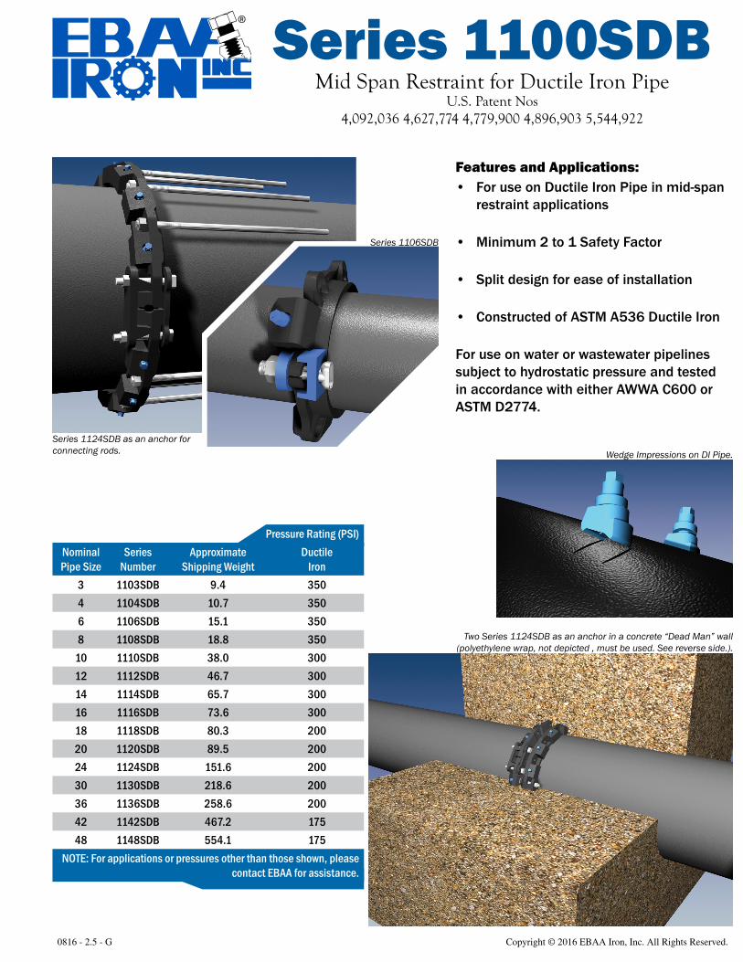
Features and Applications:• For use on Ductile Iron Pipe in mid-span
restraint applications
• Minimum 2 to 1 Safety Factor
• Split design for ease of installation
• Constructed of ASTM A536 Ductile Iron
For use on water or wastewater pipelines subject to hydrostatic pressure and tested in accordance with either AWWA C600 or ASTM D2774.
Pressure Rating (PSI)NominalPipe Size
SeriesNumber
ApproximateShipping Weight
DuctileIron
3 1103SDB 9.4 3504 1104SDB 10.7 3506 1106SDB 15.1 3508 1108SDB 18.8 350
10 1110SDB 38.0 30012 1112SDB 46.7 30014 1114SDB 65.7 30016 1116SDB 73.6 30018 1118SDB 80.3 20020 1120SDB 89.5 20024 1124SDB 151.6 20030 1130SDB 218.6 20036 1136SDB 258.6 20042 1142SDB 467.2 17548 1148SDB 554.1 175
NOTE: For applications or pressures other than those shown, please contact EBAA for assistance.
Series 1106SDB
Series 1124SDB as an anchor for connecting rods. Wedge Impressions on DI Pipe.
Two Series 1124SDB as an anchor in a concrete “Dead Man” wall (polyethylene wrap, not depicted , must be used. See reverse side.).
0816 - 2.5 - G Copyright © 2016 EBAA Iron, Inc. All Rights Reserved.
1. Remove the clamps from the split gland. Loosely assemble the halves on the pipe by assembling each clamp so that the angled surfaces of the clamp mate with the angled surfaces on each side of the split, and with the backup plate on the opposite side of the gland from the clamp. Insert the long T-bolt (provided) through the clamps and tighten hand tight.
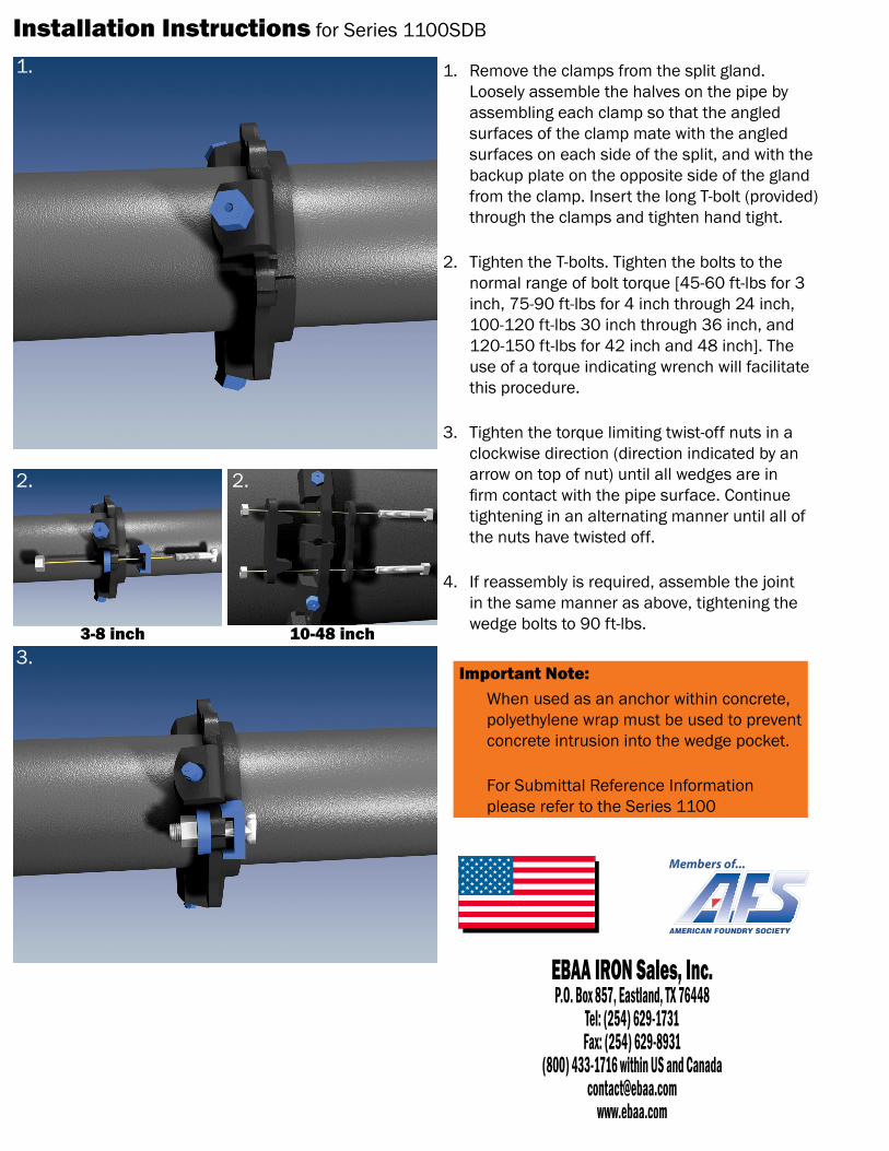
2. Tighten the T-bolts. Tighten the bolts to the normal range of bolt torque [45-60 ft-lbs for 3 inch, 75-90 ft-lbs for 4 inch through 24 inch, 100-120 ft-lbs 30 inch through 36 inch, and 120-150 ft-lbs for 42 inch and 48 inch]. The use of a torque indicating wrench will facilitate this procedure.
3. Tighten the torque limiting twist-off nuts in a clockwise direction (direction indicated by an arrow on top of nut) until all wedges are in firm contact with the pipe surface. Continue tightening in an alternating manner until all of the nuts have twisted off.
4. If reassembly is required, assemble the joint in the same manner as above, tightening the wedge bolts to 90 ft-lbs.
Installation Instructions for Series 1100SDB
1.
2. 2.
3.3-8 inch 10-48 inch
Important Note:When used as an anchor within concrete, polyethylene wrap must be used to prevent concrete intrusion into the wedge pocket.
For Submittal Reference Information please refer to the Series 1100