Embed Size (px)
Citation preview

Series 150Multi-Parameter Instrument - Instruction Manual
pH/ORPDO
CD/TDS

22
Table of Contents1. Specifications .................................................................................. 1
1.1 General Specifications .................................................................... 1
1.2 Electrical Specifications .................................................................. 2
2. Front Panel Description .................................................................. 5
3. pH/mV Measuring and Calibration
Procedure ........................................................................................ 7
4. Conductivity/TDS Measuring and
Calibration Procedure .................................................................. 13
5. DO (Dissolved Oxygen) Measuring
and Calibration Procedure ........................................................... 18
6. Data Load, Data Record, Data Logger ........................................ 24
7. Advanced Adjustment Procedure ................................................ 26
7.1 Check Memory Space ................................................................... 27
7.2 Clear Memory ............................................................................... 27
7.3 Date/Time Setting ......................................................................... 27
7.4 Sample Time Setting ..................................................................... 27
7.5 Auto Power Off Default Setting .................................................. 28
7.6 Temp. Unit Default Setting .......................................................... 28
7.7 pH Manual Temp. Value Setting .................................................. 28
7.8 CD Temp. Compensation Factor Setting...................................... 28
7.9 CD ( µS, mS ), TDS ( ppm ) Setting ............................................... 29
7.10 DO % Salt Compensation Value Setting ..................................... 29
7.11 DO Height (Altitude) Compensation Value Setting ................... 30
7.12 Escape from the Setting function ................................................ 30
8. Data Output .................................................................................. 31
9. RS232 PC Serial Interface .............................................................. 33
10. Battery Replacement .................................................................... 35
11. System Reset ................................................................................. 35
11. Optional Accessories ..................................................................... 36

1
1. Specifications
1.1 General Specifications
Circuit Custom microprocessor LSI
Display LCD size : 58 mm x 34 mm.
Measurement pH / Oxidation Reduction Potential (ORP)
Conductivity/Total Dissolved Solids (TDS)
Dissolved Oxygen (DO)
Temperature
Sampling Time of Data Log-ger
1 second to 8 hours 59 minutes and 59 seconds
Data Hold Freeze the display reading.
Memory Recall Maximum and Minimum value
Power off •Auto shut off saves battery life;manualshutoffpossiblebypressing“Power”buttonfor 2 seconds
•Default changeable: auto power off/ manual power off
•Withdefaultsetatautopoweroff,powerwill off automatically after 10 minutes if no buttonispressed.
Display lapse time Approx.1second.
Data Output RS 232 PC serial interface
Operating Temperature 0 to 50 °C (32 to 122°F) for the instrument (notincludingprobes)
Operating Humidity Less than 80% rel. humidity
Power Supply •DC1.5Vwith4batteries (mignonsize; TypeAA)
•DC9Vbyadapterinput
Power Current •Operation:approx.DC28mA
•Clock(poweroff):approx.DC1µA

2
Weight • instrument390g(batteriesincluded)
•withprotectivecovering620g
Dimension instrument:203x76x38mm•
with protective covering: approx. •220 x 125 x 45 mm
1.2 Electrical Specifications (23± 5°C)
A. pH/mV
Measurement pH 0 to 14 pH
mV -1999mVto1999mV
Input Impedance 1012 ohm
Temperature Compensation for pH measurement
Manual 0 to 100°C
(32 to 212°F)
Automatic(ATC) 0to65°C
(32 to 149 °F) with tem-peratureprobe
pHCalibration 1to3pointcalibrationusing
pH7/pH4/pH10buffersolutions
Threepointcalibrationensuresbestlinearityand accuracy
Measurement Range Resolution Accuracy
pH 0 to 14 pH 0.01 pH ± (0.02 pH + 2 digits)
mV -1999to1999mV 1mV ± (0.5 % pH + 2 digits)
*pHaccuracyisbasedoncalibratedmeteronly.

3
B. Conductivity
Conductivityprobe Carbon rod electrode for longlife
Function •Conduction(µS,mS)
•TotalDissolvedSolids(ppm)
•Temperature(°C,°F)
Temperature Compensation Automatic from 0 to 60°C (32–140°F),
with temperature compensa-tion factor variable between 0 to 5 % per °C
ProbeOperatingTemperature 0to60°C(32to140°F)
ProbeDimension Round, 22 mm diameter x 120 mm length
ProbeWeight approx.65g
Range Measurement Resolution Accuracy
200µS 0to200.0µS/cm 0.1µS/cm ± (2 % F.S. + 1 digit)2 mS 0.2 to 2.000 mS / cm 0.001 mS / cm
20 mS 2 to 20.00 mS / cm 0.01 mS / cm
200 mS 20 to 200.0 mS / cm 0.1 mS / cm
F.S. = Full Scale

4
C. TDS (Total Dissolved Solids)
Range Measurement Resolution Accuracy
200 ppm 0 to 132 ppm 0.1 ppm ± (2 % F.S. + 1 digit)2,000ppm 132to1,320ppm 1 ppm
20,000ppm 1,320to13,200ppm 10 ppm
200,000ppm 13,200to132,000ppm 100 ppm
F.S. = Full Scale
D. Temperature
Function Measurement Resolution Accuracy
°C 0°Cto60°C 0.1°C ± 0.8°C
°F 32°F to 140°F 0.1°F ± 1.5°F
E. Dissolved oxygen
OxygenProbe Polarographictypeoxygenprobe
ProbeCompensation
andAdjustment
Temperature 0to50°C,automatic,
(3 to 122 °F)
Salt 0 to 39 % Salt
Height 0 to 8900 meter
ProbeWeight approx. 195 g
ProbeSize Round,190mmlengthx28mmdiameter
Measurement Range Resolution Accuracy(23±5°C)
Dissolved Oxygen 0 to 20.0 mg/L 0.1 mg/L O2 ± 0.4 mg/L O2
OxygeninAir 0 to 100 % 0.1 % O2 ± 0.7 % O2

5
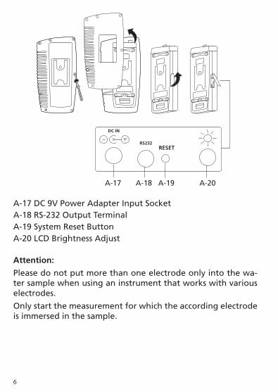
2. Front Panel Description (Fig. A)
A-1 DisplayA-2 Power ButtonA-3 REC Button (Enter Button)A-4 HOLD Button (ESC Button)A-5 Mode Button ( Up Button, Zero Button)A-6 Function Button (Range Button, Down Button)A-7 Send Button (Clock Button)A-8 SET Button (Logger Button)A-9 StandA-10 Battery Compartment CoverA-11 Battery Cover ScrewA-12 Tripod Fix NutA-13 Temp. Socket (pH ATC Socket)A-14 CD SocketA-15 DO SocketA-16 pH Socket (BNC Socket)
A-2 A-3 A-4 A-5 A-6 A-7 A-8
A-1
A-15A-14A-13
A-16
A-12 A-9 A-11 A-10
6
A-17 DC 9V Power Adapter Input SocketA-18 RS-232 Output TerminalA-19 System Reset ButtonA-20 LCD Brightness Adjust
Attention:
Please do not put more than one electrode only into the wa-ter sample when using an instrument that works with various electrodes.
Only start the measurement for which the according electrode is immersed in the sample.
A-17 A-18 A-19 A-20
DC IN
RS232RESET

7
3. pH/mV Measuring and Calibration Procedure
Display layoutMeasurementValue
PH
Manual Temp.25.0 °C
Temp. value Temp unit
pH
or
mV
Manual Temp. or
AutoTemp.
10.00
The meter default settings are as follows:•The display unit is set to pH.• The temperature unit is set to °C.
• Manual temperature setting (without ATC probe connection)
• Auto power off.
• Data logger function sampling time: 2 seconds.

8
3.1 pH measurement (with manual temperature setting)
1)AttachthepHElectrodebyinstallingthe“ProbePlug“ (Fig.B-1)intothe“pHSocket/BNCSocket“(Page5,Fig.A-16). 2)Turnontheinstrumentbypressingthe“Power”buttononce.
3)Keeppressingthe“Mode”buttonuntilthedisplayofbottom rightshows“pH“and“ManualTemp.“indicator.
4) Adjust the Manual Temp. value exactly to the same temperature as the solution. For procedure refer to chapter 7.7, page 28. 5)RemovecapandholdthepHElectrodebody(Fig.B-2)andcom- pletelyimmersethe“SensingHead“(Fig.B-3)inthesolutionto bemeasuredandgentlyswirltheprobe.
6)TheupperdisplaywillshowthepHvalue,thebottomleftdisplay will show the Manual Temp. setting.
Fig. B
B-1
B-2
B-3
B-4

9
3.2 pH measurement (with ATC , automatic Temperature Compensation)
1)Alltheproceduresarethesameasfor3.1“pHmeasurement (manualtemperaturesetting)“,exceptforattachmentofa temperatureprobebyinsertingtheplugofthetemperature probeintothe“Temp.Socket“(Page5,Fig.A-13),andimmers- ingthesensingheadofthetemperatureprobeintothemeasure- ment solution.
2)TheupperdisplaywillshowthepHvalue,thebottomleft displaywillshowtheTemp.valueofthemeasuredsolution,and thebottomrightdisplaywillshow“AutoTemp.“asexamplebelow:
When not in use the “Electrode Sensing Head“ (Page 8, Fig. B-3) should always be immersed in water by part-filling the probe cap, (Page 8, Fig. B-4) and ensuring that the cap is firmly lifted onto the probe. Failure to do so will reduce probe life.
3.3 mV Measurement
TheinstrumenthasabuiltinmV(millivolt)measurementfunction,whichenablesyoutomakeion-selective,ORP(oxidationreductionpotential),andotherprecisemVmeasurements.
1)AttachtheORPElectrodebyinstallingthe“ProbePlug“ofthe ORPelectrodeintothe“pHSocket/BNCSocket“(Page5,Fig.A-16).
2)Poweronthemeterbypressingthe“Power”buttononce.
3)Keeppressingthe“Mode”buttonuntilthedisplayatbottom rightshows“PH“and“ManualTemp.“indicator.
PH
Auto Temp.25.0 °C
7.01
10
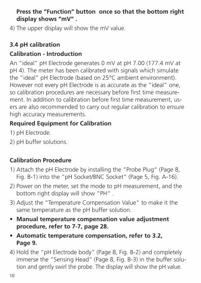
Press the “Function” button once so that the bottom right display shows “mV“ .
4)TheupperdisplaywillshowthemVvalue.
3.4 pH calibration
Calibration - Introduction
An“ideal”pHElectrodegenerates0mVatpH7.00(177.4mVatpH4).Themeterhasbeencalibratedwithsignalswhichsimulatethe“ideal”pHElectrode(basedon25°Cambientenvironment).HowevernoteverypHElectrodeisasaccurateasthe“ideal”one,socalibrationproceduresarenecessarybeforefirsttimemeasure-ment.Inadditiontocalibrationbeforefirsttimemeasurement,us-ersarealsorecommendedtocarryoutregularcalibrationtoensurehigh accuracy measurements.
Required Equipment for Calibration
1)pHElectrode.
2)pHbuffersolutions.
Calibration Procedure
1)AttachthepHElectrodebyinstallingthe“ProbePlug“(Page8, Fig.B-1)intothe“pHSocket/BNCSocket“(Page5,Fig.A-16).
2)Poweronthemeter,setthemodetopHmeasurement,andthe bottomrightdisplaywillshow“PH“.
3)Adjustthe“TemperatureCompensationValue“tomakeitthe sametemperatureasthepHbuffersolution.
• Manual temperature compensation value adjustment procedure, refer to 7-7, page 28.
• Automatic temperature compensation, refer to 3.2, Page 9.
4)Holdthe“pHElectrodebody“(Page8,Fig.B-2)andcompletely immersethe“SensingHead“(Page8,Fig.B-3)inthebuffersolu- tionandgentlyswirltheprobe.ThedisplaywillshowthepHvalue.

11
5)Pressthe“REC”buttonand“HOLD”buttonatthesametime. Thedisplaywillshowthefollowingscreenasanexample.Now release.
6)• IfthebuffersolutionispH7.0(±1pH),theupperdisplaywill show 7.00 automatically.
• IfthebuffersolutionispH4.0(±1pH),theupperdisplaywill show 4.00 automatically.
• IfthebuffersolutionispH10.0(±1pH),theupperdisplay will show 10.00 automatically.
• IfthebuffersolutionvalueisbeyondpH7.00,pH4.00, pH10.00(forexample7.01,4.02,10.03)thenuse
“ ”button,“ ”buttontoadjustthedisplayvaluetoexactly matchthepHbuffersolutionvalue.
7)Pressthe“Enter”buttontwicetosavethecalibrationdataand finishthecalibrationprocedure.
8)Thedescribedprocedurecanbeperformedforthefollowing calibrationpoints:
pH7 calibration
pH4 calibration
pH10 calibration
•CalibrationshouldalwaysstartwithpH7,followedbypH4and/ orpH10calibration.
•Rinsetheelectrodewithdistilledwaterbeforeeachcalibration point.
PH CAL.
^, v Enter : Y23.5 °C
7.00
12
•Repeattheabovecalibrationproceduresatleasttwicetoensure accuracy.
3.5 ORP calibration
1)AttachtheORPelectrode(optional,ORP-14)byconnectingthe ORP electrode to the meter.
2)Poweronthemeter,andsetthemodeandfunctionto“mV“ (refertochapter3.3,Page9).
3) Immerse the sensing head of the ORP electrode in the ORP standardbuffersolution.TheupperdisplaywillshowtheORP valueinmV.
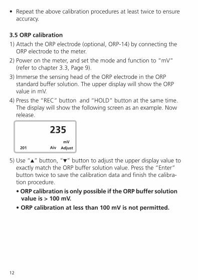
4)Pressthe“REC”buttonand“HOLD”buttonatthesametime. Thedisplaywillshowthefollowingscreenasanexample.Now release.
5)Use“ ”button,“ ”buttontoadjusttheupperdisplayvalueto exactlymatchtheORPbuffersolutionvalue.Pressthe“Enter” buttontwicetosavethecalibrationdataandfinishthecalibra- tion procedure.
• ORP calibration is only possible if the ORP buffer solution value is > 100 mV.
• ORP calibration at less than 100 mV is not permitted.
mV
Adjust201
235
Aiv

13
4. Conductivity/TDS Measuring and Calibration Procedure
Display layoutMeasurementValue
200.0 µS
Auto Range24.2 °C
Temp. value Temp unit AutoorManual
range
19.00
The meter default settings are as follows:•Thedisplayunitissettoconductivity(µS,mS).•Thetemperatureunitissetto°C.•Temp.compensationfactorissetto2.0%per°C.•Autorange.•Autopoweroff.•Dataloggerfunctionsamplingtime: 2 seconds.
Range
scale
14
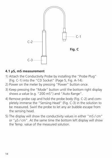
4.1 µS, mS measurement
1)AttachtheConductivityProbebyinstallingthe“ProbePlug“ (Fig.C-1)intothe“CDSocket“(Page5,Fig.A-14). 2)Poweronthemeterbypressing“Power”buttononce.
3)Keeppressingthe“Mode”buttonuntilthebottomrightdisplay showsavalue(e.g.“200mS“)and“AutoRange“.
4)Removeprobecapandholdtheprobebody(Fig.C-2)andcom- pletelyimmersethe“SensingHead“(Fig.C-3)inthesolutionto bemeasured.Swirltheprobetoletanyairbubbleescapefrom the sensing head.
5)Thedisplaywillshowtheconductivityvaluesineither“mS/cm” or“µS/cm”.Atthesametimethebottomleftdisplaywillshow the Temp. value of the measured solution.
Fig. C
C-1
C-2
C-3

15
Manual range operation
The meter default is set to auto range mode. Under auto range measurement,thebottomrightdisplaywillshowthe“AutoRange“indicator.Ifmanualrangemodeisrequired,theproceduresare as follows:
1)Pressthe“Range”buttoncontinuouslyforatleasttwoseconds untilthebottomrightdisplayshowsthe“ManualRange“indica- tor.Releasethe“Range”button.Nowthemeterissetformanual range operation.
2)Pressthe“Range”buttononcetochangetherange.Therange (200µS,2mS,20mS,200mS)willshowunderthemeasure- ment value.
3)• Ifthedisplayshows“ ---- “,itindicatesanoverrange.
Selectthenext,higherrange.
• Ifthedisplayshows“ ----“,itindicatesanunderrange. Selectthenext,lowerrange.
4)TochangeManualRangebacktoAutoRange,pressthe “Range”buttoncontinuouslyforatleasttwosecondsuntilthe bottomrightdisplayshowsthe“AutoRange“Indicator.Release the“Range”button.NowthemeterissetforAutorangemode again.
Change the Temp. unit to °F
TochangetheTemp.unitfrom°Cto°F,pleaserefertopage28,chapter7.6(Temp.UnitDefaultSetting)
Change the Temp. Coefficient Factor
The default Temp. compensation factor value of the measurement solutionissetto2.0%per°C.Tochangeit,pleaserefertopage28,chapter7.8(Temp.CompensationFactorSetting).

16
4.2 TDS (ppm) measurement
Measuringproceduresarethesameasabove4.1 Conductivity (µS, mS) measurement,exceptforchangingthedisplayunitfromµS,mStoppm.Fordetailedprocedurespleaserefertopage29,chapter7.9CD(µS,mS),TDS(ppm)Setting.
4.3 Calibration
1)Obtainathestandardconductivitysolution: For example :
• 2mSrangecalibrationsolution:
1.413 mS Conductivity Standard Solution
• 200µSrangecalibrationsolution:
80 µS Conductivity Standard Solution
• 20mSrangecalibrationsolution:
12.88 mS Conductivity Standard Solution
or other Conductivity Standard Solution
2)Installthe“ProbePlug“(Page14Fig.C-1)intothe“CDSocket“ (Page5,Fig.A-14).
3)Poweronthemeter,andsetthemodetoconductivity
measurement(µS,mS).
4)Holdtheprobebody(Page14,Fig.C-2)andcompletelyimmerse “SensingHead“(Page14,Fig.C-3)inthestandardsolution. Swirltheprobetoletanyairbubbleescapefromthesensing head. The display will show the conductivity mS ( mS ) values.
5)Pressthe“REC”buttonand“HOLD”buttonatthesametime. Thedisplaywillshowthefollowingscreen,asanexample.Now release.

17
6)Use“ ”button(Page5,Fig.A-5),“ ”buttontoadjustthe upper display value to match the standard conductivity value. 7)Pressthe“Enter”buttontwicetosavethecalibration data,andfinishthecalibrationprocedure.
• If only one calibration point is needed, just set the 2 mS range (1.413 mS Cal.). • A multi-point calibration procedure should always start with 2 mS range (1.413 mS Cal.), then proceed to other ranges (20 µS range, 20 mS range or 200 mS range) if necessary.
CD CAL.
^, v ENTER: Y23.5 °C
1.413

18
Display layout MeasurementValue
% O2
24.2 °C
Temp. value Temp unit Temp. unit % O2 or mg/L
20.9
5. DO (Dissolved Oxygen) Measuring and Calibration Procedure
ATTENTION: Make sure the Oxygen probe is filled with Elec-trolyte!
To fill the Probe‘s Electrolyte, refer to chapter 5.3 “Probe maintenance“, page 22.
The meter default settings are as follows: •Thedisplayunitissetto%O2. •Thetemperatureunitissetto°C. •Autopoweroff. •Dataloggersamplingtime:2seconds.

19
5.1 Dissolved Oxygen measurement
Fig. D
1)AttachtheOxygenProbebyinstallingthe“ProbePlug“(Fig.D-1) intothe“DOSocket“(Page5,Fig.A-15).2)Poweronthemeterbypressingthe“Power”buttononce.3)Keeppressingthe“Mode”buttonuntilthebottomrigthdisplay shows“%O2“.
CAUTION! Ensure calibration on air before measurement.Wait approx. 2 minute until the reading value stabilizes. If the reading value on air is not within 20.7 to 21.1 (20.9 ± 0.2), then proceed with calibration procedures first. For calibration procedures, please refer chapter 5.2, page 21. After completing the calibration procedures, the display should show a value between 20.8 and 21.0 (20.9 ± 0.1).
4)Pressthe“Function”buttononce,andthebottomrightdisplay willshow“mg/L“.NowthemeterisreadyfortheDissolved Oxygen measurement.
D-1D-2
D-3
D-5
D-4

20
5)• Removetheprotectivecoverfromtheprobeheadand immersetheprobetoadepthofatleast10cminthemeas- uredliquidinorderfortheautomatictemperaturecompensa- tiontotakeeffect. •Thermalequilibriummustoccurbetweentheprobe&the measurementsample,whichusuallytakestoafewminutes iftheTemp.differencebetweenthetwoisonlyafewdegrees Celsius. •Tomeasurethedissolvedoxygencontentinanygiven liquid,itissufficienttoimmersethetipoftheprobeinthe solution,makingsurethatthevelocityoftheliquidcoming intocontactwiththeprobeisatleast0.2-0.3m/s.Thisis achievedbyswirlingtheprobeinthesolution. •Duringlaboratorymeasurements,theuseofamagnetic stirrer/agitatorisrecommended.Inthisway,errorsduetoair diffusion in the solution are reduced to a minimum. 6)ThedisplaywillshowtheDissolvedOxygenvalues(mg/L).Atthe sametime,thebottomleftdisplaywillshowtheTemp.valueof the measured solution. 7)Rinsetheprobecarefullywithnormaltapwateraftereach series of measurements.
Oxygen in the air Whenthedisplayunitshows“%O2“,thisrepresentsanapproxi-mate air Oxygen value. Changing the Temp. unit to °F TochangetheTemp.unitfrom°Cto°F,pleaserefertopage28,chapter7.6(Temp.UnitDefaultSetting).
“% Salt“ compensation value adjustment Tochangethe%Saltcompensationvalue,refertopage29,chap-ter 7.10 (% Salt Compensation value Setting).

21
“Height“ (Altitude) compensation value adjustment TochangetheHeightcompensationvalue,pleaserefertopage 29,chapter7.11(HeightCompensationvalueSetting).
5.2 Calibration 1)Installthe“ProbePlug“(Page19,Fig.D-1)intothe“DOSocket“ (Page5,Fig.A-15).2)Poweronthemeterbypressingthe“Power”buttononce.3)Keeppressingthe“Mode”buttonuntilthebottomrightdisplay shows“%O2“. Wait for at least 5 minutes until the display reading values stabilise with no fluctuation. 4)Pressthe“REC”buttonand“HOLD”buttonatthesametime. Thedisplaywillshowthefollowingscreen,asanexample.Now release.
5)Pressthe“Enter”buttontwice.Thiswillsavethecalibrationdata andfinishthecalibrationprocedure.Finallythelowerdisplay willshow“O2CAL.OK“.Returntothenormalscreen. Thecompletecalibrationprocedurewilltakeapproximately30 seconds. Calibration - additional information: As oxygen in air is typically 20.9 %, use ambient air 02 for quick & precise calibration.
O2 CAL.
ESC:N ENTER: Y23.5 °C
20.9

22
5.3 DO Probe maintenance
a) First time use of the meter: TokeeptheDOprobeinthebestcondition,besuretofillthe OxygenProbe,withElectrolytepriortofirstuse.
b) After using the probe for a certain period: Iftheusercannotcalibratethemeterproperlyorthemeter‘s readingsarenotstable,pleasechecktheoxygenprobetosee iftheelectrolyteintheprobeheadcontainerhasrunoutorthe diaphragm(insidetheprobehead)hasaproblem(e.g.isdirty). Ifyes,pleasefilltheelectrolyteorchangethediaphragmset. Thenre-calibrate.
Diaphragm (probe head including diaphragm set):AkeycomponentoftheoxygenprobeisthethinTeflondiaphragmhousedinthetipoftheprobe.Thisdiaphragmispermeablebyoxygenmoleculesbutnotbytheconsiderablylargermoleculescontainedintheelectrolyte.Accordinglyoxygenmaydiffusethroughouttheelectrolytesolutioncontainedintheprobe,anditsconcentrationmaybequantifiedbythemeasurementcircuit.Thissensitive diaphragm is rather delicate and is easily damaged if it comesintocontactwithsolidobjectsorissubjectedtoknocks.Ifthediaphragmisdamagedortheelectrolytehasrunout,pleaseseefollowing procedure:

23
1)Unscrewthe“ProbeHead“(Page23,FigE-3).2)PourouttheoldElectrolytefromthecontainerin the“Probehead“.3)FillthecontainerwithnewElectrolyte.4)Screwtheprobehead(FigE-3)backontothe probebody.5)Whennotinuse,inserttheprobeheadintothe probeprotectioncover(Page19,Fig.D-5)thatis equippedwithawetsponge.
ProbeElectrolyte
ProbeheadincludingDiaphragm set
E-1
E-2 E-3
Fig.E
E-1Probebody
E-2Temp.sensor
E-3Probehead

24
6. Data Load, Data Record, Data Logger
6.1 Data Hold Duringthemeasurement,pressthe“Hold”buttononcetoholdthemeasuredvalueandtheLCDwilldisplaya“HOLD“symbol.Pressthe“Hold”buttononceagaintoreleasethedataholdfunction.
6.2 Data Record (MAX, MIN reading) 1) The data record function records the maximum and minimum readings.Pressthe“REC”buttononcetostarttheDataRecord functionanda“REC“symbolwillbedisplayed.2)Withthe“REC“symbolonthedisplay: a)Pressthe“REC”buttononcemore.The“RECMAX“symbol along with the maximum value will appear on the display. To deletethemaximumvalue,justpressthe“Hold”buttononce. Thedisplaywillthenshowonlythe“REC“symbolandthe meter will continue to record data in the memory. b)Pressthe“REC”buttonagain.The“RECMIN“symbolalong with the minimum value will appear on the display. To deletetheminimumvalue,justpressthe“Hold”buttononce. Thedisplaywillthenshowonlythe“REC“symbolandthe meter will continue to record data in the memory. c)Toexitthememoryrecordfunction,justpressthe“REC“ buttonforatleast2seconds.Thedisplaywillreverttothe current reading.
6.3 Data Logger Thedataloggerfunctioncansave16,000readingswithtimeanddate.(Realtimedataloggerwithbuilt-in-clock(hour-min-sec.,year-month-date)).

25
The data logger procedure is as follows: a)Pushingthe“Logger”buttononcewillshowthesamplingtime valueonthebottomleftdisplaythendisappeared.b)Pressthe“REC”buttononcetostarttheDataRecordfunction anda“REC“symbolwillbedisplayed.c) Auto Data Logger
TheSamplingfrequencycanbesetfrom1secto8h 59min 59sec (refer to chapter 7.4 page 27). E.g.:Ifasamplingfrequencyof1minisset,themeter stores the measured value every minute until the data logger function is stopped. Press the“Logger”buttononcetostarttheAutoDataLoggerfunction,atthesamethebottomrightdisplaywillshowtheindicator“Recording....“.NowtheDataLoggerfunctionhasstarted.Theupperdisplaywillshowa“DATA“indicatoralongwith“REC“marker.Pressthe“Logger”buttononcetostopthedata
loggerfunction.The“DATA“indicatorwilldisappear.Ifyoupress theLoggerbuttononcemoretheDataLoggerfunctionwill re-start. d) Manual Data Logger (Sampling time is set to 0 second). Please refertochapter7.4page27.Pressthe“Logger”buttononce tosaveonesetofdatainthememory.Atthesametimethe bottomrightdisplaywillflashtheindicator“Recording....“.Now the Data logger function has started. The upper display will show the“DATA“indicatoralongwiththe“REC“marker.e) Memory full Withthedataloggerinaction,ifthebottomrightdisplayshows “Full“,itindicatesthememoryhasover16,000setsandis therefore full.
TofindouttheFreeMemory,pleaserefertochapter7.1,Page•27. Toclearthememoryofdata,pleaserefertochapter7.2,Page•27.
25.5°C 2.000 mSAutoRange
25.5°C 2.000 mSAutoRange
REC DATA

26
7. Advanced Adjustment ProceduresBeforecarryingoutthefollowingAdvancedAdjustmentProceduresexitthe“Holdfunction“andthe“Recordfunction“first.Thedis-playwillnotshowthe“HOLD“andthe“REC“marker.
1)Pressthe“SET”buttonforatleasttwosecondsuntilthelower display shows:
XXXXXMemorySpace
Pushthe“ESC”buttontoreturntothenormalmeasuringdisplay.
2)Toselect“AdvancedSettingFunction”,pressandholdtheSET button,thenpressagaintosuccessivelyshowthefollowing:
7.1 Memory Space 7.2 Clear Memory 7.3 Date/Time Set 7.4 Sample Time 7.5AutoPowerOff7.6Temp.Unit
The following functions appear only if the corresponding measure-mentfunctionisselected(pH,CD,DO)7.7M.TEMP.SET(pHmode) 7.8 Temp. Comp. (CD mode) 7.9CD,TDSSelect(CDmode) 7.10%SaltSET(DOMode)7.11HeightValue(DOMode) 7.12ESC->Finish

27
3)TomakeadvancedAdjustments,usethefollowingbuttons: “ESC”,“Enter”,“ ”Up,“ ”Down,“SET”.
7.1 Check Memory Space Tocheckthefreememory,pressandholdtheSETbuttonforatleast 2 seconds. The display will show.
XXXXX MemorySpace
XXXXXisthefreememorybalance.ForexampleXXXXX=15417.
7.2 Clear Memory To delete readings from the memory: • PushENTERbuttontwicetoconfirm.•PresstheESCbuttononcetoquit,andreturntothemain measurement display.
7.3 Date/Time Setting • Use“ ”Up,“ ”Downand“Enter”(->)tosettheDate(year- month-date) and the Time (hour-min-sec). •AfterDate/Timeadjustment,pushthe“Enter”button, thenpressthe“ESC”buttontosavetheclockdataintothe memory,andreturntothenormaldisplay.
7.4 Sample Time Setting •Use“ ”Up,“ ”Downand“Enter”(->)toselecttheSample Time (hour-min-sec). •AfterSampleTimeadjustment,pushthe“Enter”button,then pressthe“ESC”buttontosavetheclockdataintothememory and return to normal display.

28
7.5 Auto Power Off Default Setting •Use“ ”Up,“ ”Downtoselect“1“or“0“.
1=AutopowerOn. 0=AutopowerOff.
• AfterAutoPowerOffadjustment,pushthe“Enter”button,then press“ESC”tosavethedataandreturntothenormaldisplay.
7.6 Temp. Unit Default Setting • Use“ ”Up,“ ”Downtoselect“1“or“0“.
1 = °F 0 = °C
•AfteradjustingtheTemperatureunit,pushthe“Enter”button, thenpress“ESC”tosavethedataandreturntothenormal display.
7.7 pH Manual Temp. Setting •Thisprocedureisonlytoadjustthemanualtemperature compensation value for pH measurement. • Thelowerdisplaywillshow:
M.TEMP.SET ^,vEnter:Y
• Use“ ”Up,“ ”DowntoselectthedesiredmanualTemp. compensation value. •Press“Enter“once,thenpress“ESC“tosavethedataand return to the normal display.
7.8 Temp. Compensation Factor Setting •ThisprocedureisonlyusedfortheConductivityfunction.•Use“ ”Up,“ ”DowntoselecttheTemp. Compensation Factor (% per °C) of the measured solution.

29
•Aftersettingthedesiredvalue,press“Enter“,thenpress“ESC” to save the data and return to the normal display. •Temp.CompensationFactoristypicallysetto2.0%perC degree. 7.9 CD (µS, mS), TDS (ppm) Default Setting •ThisprocedureisonlyusedfortheConductivityfunction.•Use“ ”Up,“ ”Downtoselect“1“or“0“.
0=µS,mS 1 = ppm • Afteradjustingtheunit(µS/mS,ppm),press“Enter”,thenpress “ESC”tosavethedataandreturntothenormaldisplay.
7.10 DO % Salt Compensation Value Setting • ThisprocedureisonlyavailablefortheDOfunction. • Thelowerdisplaywillshow:
%SaltSET ^,vEnter:Y
• Use“ ”Up“,“ ”Downtoselectthedesired%SaltCompen- sationValue.•Press“Enter”once,thenpress“ESC”tosavethedataand return to the normal display. •%Saltistypicallysetto0%.

30
7.11 DO Height (Altitude) Compensation Value Setting • ThisprocedureisonlyfortheDOfunction.• Thelowerdisplaywillshow:
0 = meter 1 = ft (foot) FT= foot 1 Foot = 0.3048 m
•Use“ ”Up,“ ”Downtoselect“0“or“1“. •Press“Enter”once,andthelowerdisplaywillshow:
HeightValue Meter • Use“ ”Up,“ ”DowntoselectthedesiredHeightvalue.•Press“Enter”once,thenpress“ESC”tosavethedataand return to the normal display. •Typicalsettingis0meter(0feet).
7.12 Escape from the SETTING function Press“ESC”oncetoquitandreturntothenormalmeasurementdisplayorpress“Enter”!
31
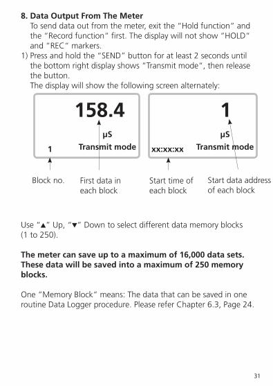
8. Data Output From The Meter Tosenddataoutfromthemeter,exitthe“Holdfunction“and the“Recordfunction“first.Thedisplaywillnotshow“HOLD“ and“REC“markers.1)Pressandholdthe“SEND”buttonforatleast2secondsuntil thebottomrightdisplayshows“Transmitmode“,thenrelease thebutton. The display will show the following screen alternately:
Use“ ”Up,“ ”Downtoselectdifferentdatamemoryblocks (1 to 250).
The meter can save up to a maximum of 16,000 data sets. These data will be saved into a maximum of 250 memory blocks.
One“MemoryBlock“means:ThedatathatcanbesavedinoneroutineDataLoggerprocedure.PleasereferChapter6.3,Page24.
µS
Transmit mode1
158.4µS
Transmit modexx:xx:xx
1
Blockno. First data ineachblock
Start time ofeachblock
Start data address ofeachblock
32
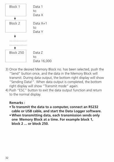
Block1 Data1 to DataX
Block2 DataX+1 to DataY
.................. ..................
Block250 DataZ to Data16,000
3)OncethedesiredMemoryBlockno.hasbeenselected,pushthe “Send”buttononce,andthedataintheMemoryBlockwill transmit.Duringdataoutput,thebottomrightdisplaywillshow “SendingData!“.Whendataoutputiscompleted,thebottom rightdisplaywillshow“Transmitmode“again.4)Push“ESC”buttontoexitthedataoutputfunctionandreturn to the normal display. Remarks : • To transmit the data to a computer, connect an RS232 cable or USB cable, and start the Data Logger software. • When transmitting data, each transmission sends only one Memory Block at a time. For example block 1, block 2 ... or block 250.

33
9. RS232 PC-Serial Interface
The instrument has an RS232 PC serial interface via the RS-232 Out Terminal“(Page6,Fig.A-18).
Dataoutputisviaa16digitstreamwhichcanbedownloadedtouser‘sspecificapplication.AnRS232leadwiththefollowingcon-nectionwillberequiredtolinktheinstrumenttothePCserialport:
MeterPC(3.5mmjackplug) (9W‚D“Connector) Center Pin........................Pin 4 Ground/shield...................Pin 2 2.2 K resister Pin 5
The16digitdatastreamwillbedisplayedinthefollowingformat:
D15D14D13D12D11D10D9D8D7D6D5D4D3D2D1D0

34
Eachdigitindicatesthefollowingstatus:
D15 StartWord=02 D14 4 D13 Sending upper display data = 1 Sending lower display data = 2 D12,D11 AnnunciatorforDisplay µS=13 mS=14 ppm=19 pH=05 mV=18 mg/L=07 %O2=06 D10 Polarity 0=Positive1=Negative D9 Decimal Point (DP) position from right to left 0=NoDP,1=1DP,2=2DP,3=3DP D8toD1 Displayreading,D1=LSD,D8=MSD For example: Ifthedisplayreadingis1234,thenD8to D1 is: 00001234 D0 EndWord=0D
RS232 setting Baudrate 9600 Parity Noparity Databitno. 8Databits Stopbit 1Stopbit

35
10. Battery Replacement1)Whentheleftcornerofthedisplayshows“ “,itisnecessary toreplacethebatteries(4xmignonsizetypeAA1.5V).2)Unscrewthesingleretainingscrew,andthenslideopenthe “BatteryCover“(Page5,Fig.A-10)andremovethebatteries.3)Replacewithnewbatteriesandslideonthecover.Replacethe retaining screw.4)Makesurethebatterycoveristightlysecuredafterchangingthe batteries.
11. System Reset Ifthemeterexperiencesproblems,suchas:
CPU system is garbled (for example, the key button cannot be operated.....).
ThensystemRESETwillfixtheproblem.ThesystemRESETproce-dure is as follows:
Useapintooltopushthe“SystemResetButton“(Page6,Fig.A-19).Thenpress“Power”onagaintofixtheproblem.

36
12. OPTIONAL ACCESSORIES
RS232cable •Computerinterfacecable.UPCB-02 •Usedtoconnectthemetertoacomputer (COM port). USBcable •Computerinterfacecable. DataLogger •Softwareusedtodownloaddatafrom software the data logger (data recorder) to a SW-DL2005 computer. DataAcquisition •TheSW-U801-WINisapowerfulmulti Software softwaredisplay(1/2/4/6/8displays) SW-U801-WINapplication,providingthe functionsofdatalogging,textdisplay, angulardisplay,chartdisplay,datarecorder high/lowlimit,dataquery,textreport,chart report.An.xxx.mdbdatafilecanberetrieved forEXCEL,ACCESS..,andotherintelligent applications.
Poweradapter AC110VtoDC9V. USAtypeplug.
Poweradapter AC220V/230VtoDC9V. Europeantypeplug.
Poweradapter AC220V/230VtoDC9V. UK type plug.
37
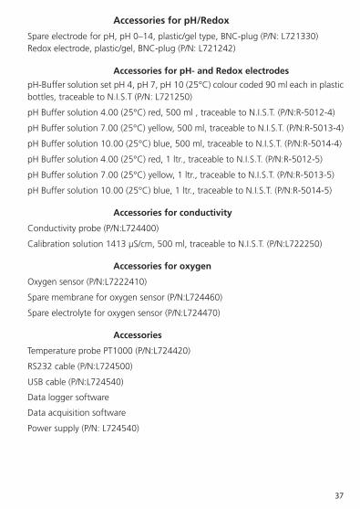
Accessories for pH/Redox
SpareelectrodeforpH,pH0–14,plastic/geltype,BNC-plug(P/N:L721330) Redoxelectrode,plastic/gel,BNC-plug(P/N:L721242)
Accessories for pH- and Redox electrodes
pH-BuffersolutionsetpH4,pH7,pH10(25°C)colourcoded90mleachinplasticbottles,traceabletoN.I.S.T(P/N:L721250)
pHBuffersolution4.00(25°C)red,500ml,traceabletoN.I.S.T.(P/N:R-5012-4)
pHBuffersolution7.00(25°C)yellow,500ml,traceabletoN.I.S.T.(P/N:R-5013-4)
pHBuffersolution10.00(25°C)blue,500ml,traceabletoN.I.S.T.(P/N:R-5014-4)
pHBuffersolution4.00(25°C)red,1ltr.,traceabletoN.I.S.T.(P/N:R-5012-5)
pHBuffersolution7.00(25°C)yellow,1ltr.,traceabletoN.I.S.T.(P/N:R-5013-5)
pHBuffersolution10.00(25°C)blue,1ltr.,traceabletoN.I.S.T.(P/N:R-5014-5)
Accessories for conductivity
Conductivityprobe(P/N:L724400)
Calibrationsolution1413µS/cm,500ml,traceabletoN.I.S.T.(P/N:L722250)
Accessories for oxygen
Oxygen sensor (P/N:L7222410)
Sparemembraneforoxygensensor(P/N:L724460)
Spare electrolyte for oxygen sensor (P/N:L724470)
Accessories
TemperatureprobePT1000(P/N:L724420)
RS232cable(P/N:L724500)
USBcable(P/N:L724540)
Data logger software
Dataacquisitionsoftware
Power supply (P/N:L724540)

TechnicalchangeswithoutnoticePrintedinGermany09/11Rev.1
Orbeco-Hellige®isaregisteredtrademarkoftheOrbeco-Hellige,Inc.
Orbeco-Hellige, Inc. 6456ParklandDriveSarasota,FL
Tel.:941.756.6410
TollFreeUS:800.922.5242Fax:[email protected]