Embed Size (px)
Citation preview
User M
anual
Allen-Bradley SLC 500 I/O
Module
s
ADV ANC EDMIC RO CON T RO L S INC.
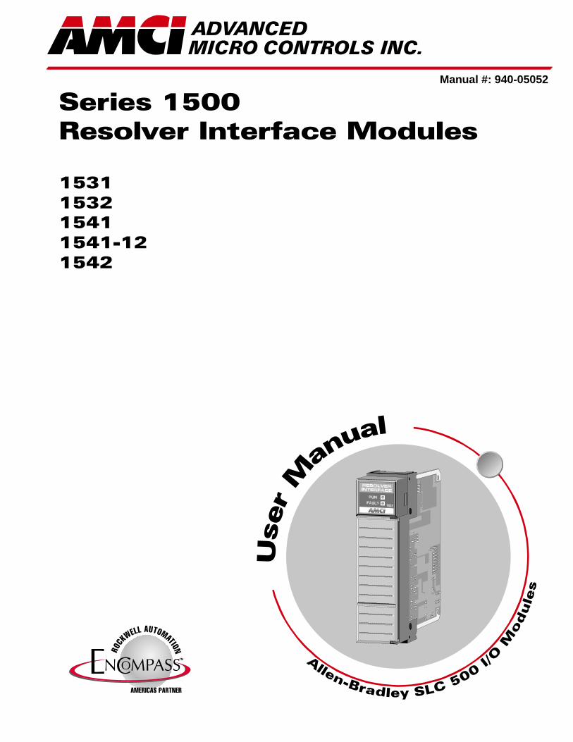
Series 1500Resolver Interface Modules
1531153215411541-121542
Manual #: 940-05052
GENERAL INFORMATION
Important User InformationThe products and application data described in this manual are useful in a wide variety of different applica-tions. Therefore, the user and others responsible for applying these products described herein are responsible for determining the acceptability for each application. While efforts havebeen made to provide accurate information within this manual, AMCI assumes no responsibility for the application or the completeness of the information contained herein.
UNDER NO CIRCUMSTANCES WILL ADVANCED MICRO CONTROLS, INC. BE RESPONSIBLE OR LIABLE FOR ANY DAMAGES OR LOSSES, INCLUDING INDIRECT OR CONSEQUENTIAL DAM-AGES OR LOSSES, ARISING FROM THE USE OF ANY INFORMATION CONTAINED WITHIN THIS MANUAL, OR THE USE OF ANY PRODUCTS OR SERVICES REFERENCED HEREIN.
Throughout this manual the following two notices are used to highlight important points.
WARNINGS tell you when people may be hurt or equipment may be damaged if the procedure is not followed properly.
CAUTIONS tell you when equipment may be damaged if the procedure is not followed properly.
No patent liability is assumed by AMCI, with respect to use of information, circuits, equipment, or software described in this manual.
The information contained within this manual is subject to change without notice.
Standard WarrantyADVANCED MICRO CONTROLS, INC. warrants that all equipment manufactured by it will be free from defects, under normal use, in materials and workmanship for a period of [1] year. Within this warranty period, AMCI shall, at its option, repair or replace, free of charge, any equip-ment covered by this warranty which is returned, shipping charges prepaid, within one year from date of invoice, and which upon examina-tion proves to be defective in material or workmanship and not caused by accident, misuse, neglect, alteration, improper installation or improper testing.
The provisions of the "STANDARD WARRANTY" are the sole obligations of AMCI and excludes all other warranties expressed or implied. In no event shall AMCI be liable for incidental or consequential damages or for delay in performance of this warranty.
Returns PolicyAll equipment being returned to AMCI for repair or replacement, regardless of warranty status, must have a Return Merchandise Authorization number issued by AMCI. Call (860) 585-1254 with the model number and serial number (if applicable) along with a description of the problem. A "RMA" number will be issued. Equipment must be shipped to AMCI with transportation charges prepaid. Title and risk of loss or damage remains with the customer until shipment is received by AMCI.
24 Hour Technical Support Number24 Hour technical support is available on this product. For technical support, call (860) 583-7271. Your call will be answered by the factory during regular business hours, Monday through Friday, 8AM - 5PM EST. During non-business hours an automated system will ask you to enter the telephone number you can be reached at. Please remember to include your area code. The system will page one of two engineers on call. Please have your product model number and a description of the problem ready before you call.
ADVANCED MICRO CONTROLS INC.
TABLE OF CONTENTS
General InformationImportant User Information ..................... IFCStandard Warranty ................................... IFCReturns Policy .......................................... IFC24 Hour Technical Support Number ........ IFC
About This ManualIntroduction .............................................. 3
Revision Record ....................................... 3Revision History ............................ 3
SpecificationsSpecifications ........................................... 4
Chapter 1: IntroductionOverview .................................................. 5
New Features ........................................... 5Backwards Compatibility ........................ 6Series 1500 Family Members .................. 6
“-19 option” ................................... 6AMCI Compatible Transducers ............... 7Other Compatible Transducers ................ 8Programmable Parameters ....................... 9
Scale Factor ................................... 9Preset Value ................................... 9Tachometer Response .................... 9Count Direction ............................. 9Transducer Fault Latch .................. 10Disable Channel 2
(1532 & 1542 only) ..................... 10Resolver Type ................................ 10
Backplane Programming .......................... 10Programming Cycle ....................... 10
Chapter 2: InstallationPower Requirements ................................ 11Installing the Module ............................... 11Module ID Code ...................................... 11Status LED’s ............................................ 12
Transducer Input Connector .................... 12
Chapter 2: Installation (continued)Transducer Cable Installation .................. 13
C1T-(x) Wiring Diagram .............. 13C2T-(x) Wiring Diagram .............. 13C1TR-(x) Wiring Diagram ........... 14
Transducer Specifications ........................ 14Connector Pin Out ........................ 14
AMCI Transducer Mounting .................... 15AMCI Transducer Outline Drawings ....... 15Autotech Transducer Installation ............. 15
Autotech Transducer Mounting .... 15Autotech Transducer Wiring ........ 16
Using AMCI and Autotech Transducers Together 16
Chapter 3: Backplane ProgrammingData Addressing ....................................... 17Programming Cycle ................................. 17Guidelines for Programming
an Older Module .................................... 17Input Image Table .................................... 18
Position and Tachometer Data ...... 18Programming Error Bits:
I:X.0/00 to I:X.0/08 .................... 18Status Bits: I:X.0/11 to I:X.0/14 ... 19Acknowledge Bit: I:X.0/15 ........... 19
Output Image Table .................................. 20Apply Preset Bits:
O:X.0/00 and O:X.0/01 .............. 20Program Bits:
O:X.0/02 to O:X.0/09 ................. 21Command Bits:
O:X.0/13 and O:X.0/14 .............. 21Transmit Bit: O:X.0/15 ................. 22Channel 1 Data Words: O:X.1-3 ... 22Channel 2 Data Words: O:X4-6 .... 22
Programming Examples ........................... 24Programming the Module ............. 24Offsetting the Transducer
Position in the SLC ..................... 25
20 Gear Drive, Plymouth Ind. Park, Terryville, CT 06786Tel: (860) 585-1254 Fax: (860) 584-1973 http:\\www.amci.com
1

TABLE OF CONTENTS
Notes
ADVANCED MICRO CONTROLS INC.2
ABOUT THIS MANUAL
Firmware rev E, software rev 6+ was released with serial number 61,750. If your 1500 has a serial number below 61,750, you can still use this manual as long as your are aware of three items.
1) All new features introduced with hardware series E are not available on your module. See New Features on page 5 for a list of these features.
2) The module does not directly support Autotech transducers unless it has the “-19” option. A RM-3 will be needed to get the Autotech transducer working with your 1500 if you do not have this option. See Using AMCI and Autotech Transducers Together on page 16 for information on using the RM-3.
3) You must not set any of the programming bits associated with the new features when you program your module. See Guidelines for Programming an Older Module on page 17 for complete information on programming your module .
IntroductionThis manual explains the operation, installation, and programming of five Series 1500 Resolver Interface Modules for the Allen-Bradley SLC 500™ programmable controller systems. These five modules are the 1531, 1532, 1541, 1542, and the 1541-12. Utilizing licensed Allen-Bradley SLC 500 I/O interface technol-ogy, these one slot Resolver Interface Modules accept one or two transducer inputs and plug directly into the A-B SLC 500 rack. Communicating through I/O registers assigned to the slot, these modules supply absolute position and tachometer data to any SLC processor from AMCI resolver based transducers. Status informa-tion is also transferred to the SLC processor.
The AMCI logo is a trademark and “AMCI” is a registered trademark of Advanced Micro Controls Inc.“SLC” and “SLC 500” are trademarks of Allen-Bradley Company.The Encompass logo is a trademark of Rockwell International.
This product incorporates technology which is licensed by Allen-Bradley Company, Inc. Allen-Bradley has not technically approved, nor does it support this product. All warranty and support for this product and its application is provided solely by Advanced Micro Controls Inc.
Manuals at AMCI are constantly evolving entities. Your questions and comments on this manual and the information it contains are both welcomed and necessary if this manual is to be improved. Please direct all comments to: Technical Documentation, AMCI, 20 Gear Drive, Terryville CT 06786, or fax us at (860) 584-1973. You can also e-mail your questions and comments to [email protected]
Revision RecordThis manual, 940-05052, supersedes 940-05051 and was first released 7/10/2000. It corrects the serial num-ber that hardware series E, firmware version 6 was released on.
Revision History940-05051: 4/14/2000. First release of Series E, Firmware 6 manual940-05050: 10/7/98. Updated illustration artwork.
LM1500056: Original cataloged manual
It is strongly recommended that you read the following manual. It was first written for the releaseof hardware series E, firmware version 6, which introduced many new features into the Series1500 modules. Backwards compatible “out-of-the-box” with older version of these modules, thenew features are easily enabled over the backplane. If there are any unanswered questions afterreading this manual, call the factory. An applications engineer will be available to assist you.
For additional information on our SLC modules as well as the rest of AMCI’s products, check outour website at www.amci.com.
20 Gear Drive, Plymouth Ind. Park, Terryville, CT 06786Tel: (860) 585-1254 Fax: (860) 584-1973 http:\\www.amci.com
3

SPECIFICATIONS
Module LocationAny SLC 500 I/O slot, including the proces-
sor slot of an extended rack. Occupies one slot.
Position TransducerDefault of AMCI brushless resolver transducer
Transducer Input Isolation1500 Vac through isolation transformers
Data Available to ProcessorTransducer Position, Velocity and Fault
Diagnostic data
Programmable ParametersResolver TypeScale Factor (counts per turn)Preset ValueTachometer ResponseCount DirectionTransducer Fault LatchDisable Channel 2 (1532, 1542 only)
Program StorageEEPROM Memory
Minimum 100,000 write cycles
Position Resolution153x: Programmable to 1 part in 1,024154x: Programmable to 1 part in 8,192
Position Update Time200 microseconds
Tachometer Resolution and Range1531, 1532, 1541, 1542:
1 RPM over 0 to 5,000 RPM range1541-12:
0.1 RPM over 0 to 3,276.7 RPM range
DC Supply Voltage from Backplane0.090A max. @ 5Vdc nominal0.055A max. @ 24Vdc nominal0.160A max. @ 24Vdc under short circuit
conditions
Environmental ConditionsOperating Temperature: 0 to 60° C
Relative Humidity: 5 to 95%(w/o condensation)
Storage Temperature: -40 to 85°
Module ID Code3513Reserves 8 Input and 8 Output Registers
Number of registers scanned can be set using SPIOGA Configuration.
Configuration software may show module as “1746-NR4: TD/Resistance Input Mod-ule”. This is normal and module will still operate correctly.
Registers Used1531, 1541, 1541-12: 3 Input, 4 Output
1532, 1542: 5 Input, 7 Output
ADVANCED MICRO CONTROLS INC.4
20 Gear Drive, Plymouth IndTel: (860) 585-1254 Fax: (8
CHAPTER 1
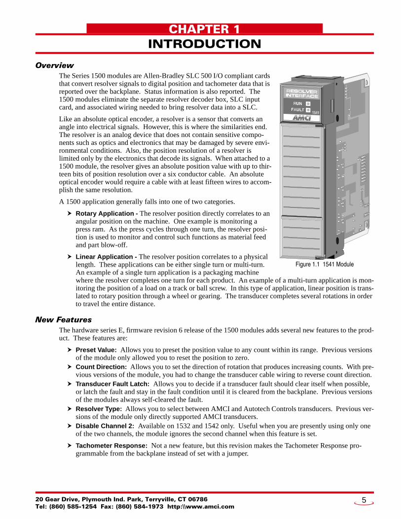
INTRODUCTIONOverviewThe Series 1500 modules are Allen-Bradley SLC 500 I/O compliant cards that convert resolver signals to digital position and tachometer data that is reported over the backplane. Status information is also reported. The 1500 modules eliminate the separate resolver decoder box, SLC input card, and associated wiring needed to bring resolver data into a SLC.
Like an absolute optical encoder, a resolver is a sensor that converts an angle into electrical signals. However, this is where the similarities end. The resolver is an analog device that does not contain sensitive compo-nents such as optics and electronics that may be damaged by severe envi-ronmental conditions. Also, the position resolution of a resolver is limited only by the electronics that decode its signals. When attached to a 1500 module, the resolver gives an absolute position value with up to thir-teen bits of position resolution over a six conductor cable. An absolute optical encoder would require a cable with at least fifteen wires to accom-plish the same resolution.
A 1500 application generally falls into one of two categories.
Rotary Application - The resolver position directly correlates to an angular position on the machine. One example is monitoring a press ram. As the press cycles through one turn, the resolver posi-tion is used to monitor and control such functions as material feed and part blow-off.
Linear Application - The resolver position correlates to a physical length. These applications can be either single turn or multi-turn. An example of a single turn application is a packaging machine where the resolver completes one turn for each product. An example of a multi-turn application is mon-itoring the position of a load on a track or ball screw. In this type of application, linear position is trans-lated to rotary position through a wheel or gearing. The transducer completes several rotations in order to travel the entire distance.
New FeaturesThe hardware series E, firmware revision 6 release of the 1500 modules adds several new features to the prod-uct. These features are:
Preset Value: Allows you to preset the position value to any count within its range. Previous versions of the module only allowed you to reset the position to zero.Count Direction: Allows you to set the direction of rotation that produces increasing counts. With pre-vious versions of the module, you had to change the transducer cable wiring to reverse count direction.Transducer Fault Latch: Allows you to decide if a transducer fault should clear itself when possible, or latch the fault and stay in the fault condition until it is cleared from the backplane. Previous versions of the modules always self-cleared the fault.Resolver Type: Allows you to select between AMCI and Autotech Controls transducers. Previous ver-sions of the module only directly supported AMCI transducers.Disable Channel 2: Available on 1532 and 1542 only. Useful when you are presently using only one of the two channels, the module ignores the second channel when this feature is set.
Tachometer Response: Not a new feature, but this revision makes the Tachometer Response pro-grammable from the backplane instead of set with a jumper.
Figure 1.1 1541 Module
. Park, Terryville, CT 0678660) 584-1973 http:\\www.amci.com
5

INTRODUCTION1
Backwards CompatibilityWith these new features, you may have some concerns if you are using a new 1531, 1532, 1541, 1541-12, or 1542 module to replace an older one, or building a new machine based on a design that used an older module. Rest assured that AMCI took backward compatibility issues into account when designing this upgrade.
With only one exception, modules built on series E, firmware 6 and later, are backwards compatible with older modules “out-of-the-box”. When shipped from the factory, all of the parameters are set to their default values, which makes the newer 1500’s behave exactly as the older ones. The only exception is the Tachome-ter Response parameter.
On older modules, the Tachometer Response was set with a jumper on the board. With the jumper installed, which was the factory default, the tachometer updated every 120 milliseconds. With it removed, the update time was 32 milliseconds. The Tachometer Response is now programmed over the backplane to either 120 or 32 milliseconds, with the default being 120 milliseconds. If you used a Tachometer Response of 120 milli-seconds, or do not use the tachometer at all, then this one exception will not affect you.
Another area of backwards compatibility is backplane programming. All backplane programming of the new features use bits and words that were previously reserved. If you followed AMCI’s suggestion and made all of these reserved bits zero in your old ladder logic and data, your program will work without error. The only reason to change your program and data is to program the new features.
Series 1500 Family MembersTable 1.1 below shows the six members of the Series 1500 family of modules. The 1541-03 and 1561 mod-ules are not covered in this manual. The comments in the table gives the name of the appropriate manual. Both manuals are available at our website, www.amci.com.
Table 1.1 Series 1500 Modules
“-19 option”An option was available on certain older 1500 modules that made them compatible with transducers from Autotech Controls. This option was denoted by adding “-19” to the end of the part number. With the release of series E, version 6, all 1500 modules can be programmed to directly support AMCI or Autotech transduc-ers. Consequently, the “-19” option is being phased out. If you are replacing a module with a “-19” option, you can now order a standard product and have the same functionality.
Model Transducer Inputs Comments
1531 1 10 bit (1,024 count) position resolution
1532 2 10 bit (1,024 count) position resolution
1541 1 13 bit (8,192 count) position resolution
1542 2 13 bit (8,192 count) position resolution
1541-12 1 13 bit (8,192 count) position resolution0.1 RPM resolution tachometer.
1541-03 112 bit (4,096 count) brake monitor module with remote dis-play. See 1541-03 Resolver Input Brake Monitor Module User Manual.
1561 1Absolute multi-turn module. 12 bit (4,096 count) per turn, 180 turns max. (737,280 maximum counts). See 1561 Multi-turn Resolver Interface Module User Manual.
ADVANCED MICRO CONTROLS INC.6
INTRODUCTION 1
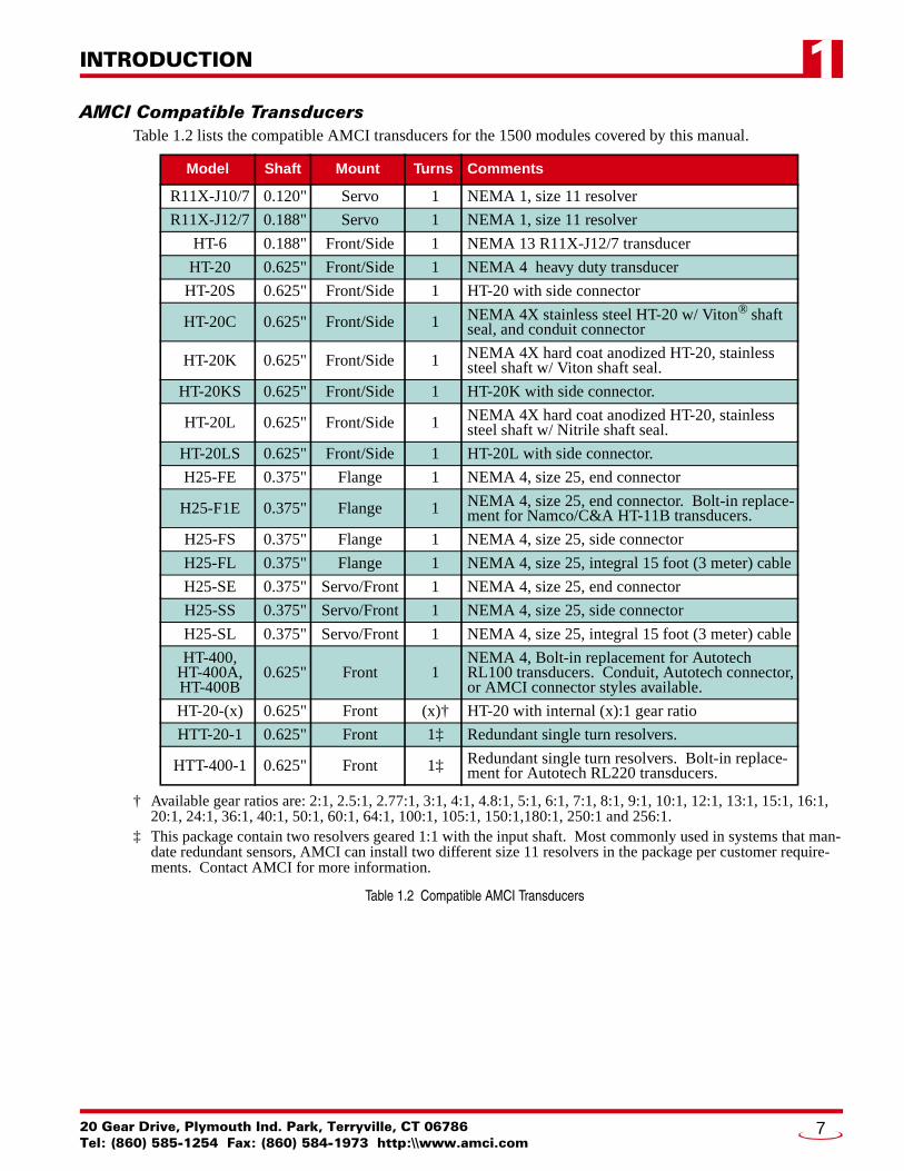
AMCI Compatible TransducersTable 1.2 lists the compatible AMCI transducers for the 1500 modules covered by this manual.
† Available gear ratios are: 2:1, 2.5:1, 2.77:1, 3:1, 4:1, 4.8:1, 5:1, 6:1, 7:1, 8:1, 9:1, 10:1, 12:1, 13:1, 15:1, 16:1, 20:1, 24:1, 36:1, 40:1, 50:1, 60:1, 64:1, 100:1, 105:1, 150:1,180:1, 250:1 and 256:1.
‡ This package contain two resolvers geared 1:1 with the input shaft. Most commonly used in systems that man-date redundant sensors, AMCI can install two different size 11 resolvers in the package per customer require-ments. Contact AMCI for more information.
Table 1.2 Compatible AMCI Transducers
Model Shaft Mount Turns Comments
R11X-J10/7 0.120" Servo 1 NEMA 1, size 11 resolver
R11X-J12/7 0.188" Servo 1 NEMA 1, size 11 resolver
HT-6 0.188" Front/Side 1 NEMA 13 R11X-J12/7 transducer
HT-20 0.625" Front/Side 1 NEMA 4 heavy duty transducer
HT-20S 0.625" Front/Side 1 HT-20 with side connector
HT-20C 0.625" Front/Side 1 NEMA 4X stainless steel HT-20 w/ Viton® shaft seal, and conduit connector
HT-20K 0.625" Front/Side 1 NEMA 4X hard coat anodized HT-20, stainless steel shaft w/ Viton shaft seal.
HT-20KS 0.625" Front/Side 1 HT-20K with side connector.
HT-20L 0.625" Front/Side 1 NEMA 4X hard coat anodized HT-20, stainless steel shaft w/ Nitrile shaft seal.
HT-20LS 0.625" Front/Side 1 HT-20L with side connector.
H25-FE 0.375" Flange 1 NEMA 4, size 25, end connector
H25-F1E 0.375" Flange 1 NEMA 4, size 25, end connector. Bolt-in replace-ment for Namco/C&A HT-11B transducers.
H25-FS 0.375" Flange 1 NEMA 4, size 25, side connector
H25-FL 0.375" Flange 1 NEMA 4, size 25, integral 15 foot (3 meter) cable
H25-SE 0.375" Servo/Front 1 NEMA 4, size 25, end connector
H25-SS 0.375" Servo/Front 1 NEMA 4, size 25, side connector
H25-SL 0.375" Servo/Front 1 NEMA 4, size 25, integral 15 foot (3 meter) cable
HT-400,HT-400A,HT-400B
0.625" Front 1NEMA 4, Bolt-in replacement for Autotech RL100 transducers. Conduit, Autotech connector, or AMCI connector styles available.
HT-20-(x) 0.625" Front (x)† HT-20 with internal (x):1 gear ratio
HTT-20-1 0.625" Front 1‡ Redundant single turn resolvers.
HTT-400-1 0.625" Front 1‡ Redundant single turn resolvers. Bolt-in replace-ment for Autotech RL220 transducers.
20 Gear Drive, Plymouth Ind. Park, Terryville, CT 06786Tel: (860) 585-1254 Fax: (860) 584-1973 http:\\www.amci.com
7

INTRODUCTION1
Other Compatible TransducersIn addition to AMCI transducers, the 1500 modules covered by this manual directly support Autotech Con-trols transducers. The Autotech supported models are:
All SAC-RL100 Transducers (Size 40, NEMA 13)All E6R and E7R-RL101 Transducers. (Size 25, NEMA 13)SAC-RL101-010 Resolvers. (Size 11, NEMA 1)All SAC-RL220 Transducers (Size 40, NEMA 13, Redundant resolvers)
If your project is a new installation, or you can budget the cost of replacing the transducer, we strongly sug-gest using AMCI transducers. AMCI is the only company in the marketplace that designs and manufactures the resolvers used in its products. Our transducers and modules are designed to work together, and will work for years to come when specified and installed properly.
If your project involves converting system originally designed for Autotech products you can most likely use AMCI transducers without re-designing transducer mounting brackets. Table 1.3 lists Autotech transducer part numbers and the AMCI bolt-in replacements. Note that the resolvers used in AMCI transducers are for AMCI products, and all connectors are AMCI standard connectors unless otherwise stated.
Table 1.3 Autotech / AMCI Transducer Cross Reference
If you decide to use your Autotech transducers, you must change the Resolver Type parameter. If you set the Resolver Type to Autotech and you are using a 1532, or 1542, then both of the transducers must be Autotech's. If you wish to bring both AMCI and Autotech transducers into a single module, you must set the Resolver Type parameter to AMCI and use an AMCI RM-3 Reference Module to connect the Autotech transducers. For more information on using AMCI and Autotech transducer, see Using AMCI and Autotech Transducers Together on page 16.
Due to differences in cable construction, AMCI does not support installations that use trans-ducer cables supplied by Autotech Controls. When using Autotech transducers, you must use Belden 9873, or Belden 9730 if your cable length is over one hundred feet. See Transducer Cable Installation on page 13 and Autotech Transducer Wiring on page 16 for information on wiring Autotech transducers.
AutotechTransducers
AMCITransducers Comments
SAC-RL101-010 R11X-J10/7 Mechanically identical except that wires come out the back instead of the side.
E6R-RL101-000EFE7R-RL101-000EF H25-FE Bolt-in replacement. Shorter body length.
E6R-RL101-000ESE7R-RL101-000ES H25-SE Bolt-in replacement when servo mounting.
Different bolt pattern on front, shorter body.
E6R-RL101-000SFE7R-RL101-000SF H25-FS Bolt-in replacement. Shorter body length, side
connector in different location.
E6R-RL101-000SSE7R-RL101-000SS H25-SS
Bolt-in replacement when servo mounting. Different bolt pattern on front, shorter body length, side connector in different location.
SAC-RL100-010 HT-400 Direct replacement.
SAC-RL100-M11 HT-400AHT-400B
Direct replacement, Autotech Connector. Direct replacement, AMCI connector.
SAC-RL220-G010C HTT-400-1 Direct replacement.
SAC-RL220-G010M HTT-400A-1HTT-400B-1
Direct replacement, Autotech Connector. Direct replacement, AMCI connector.
ADVANCED MICRO CONTROLS INC.8
INTRODUCTION 1
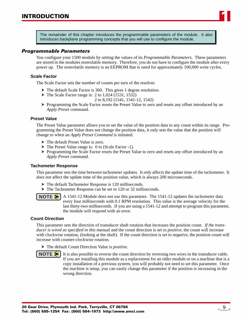
Programmable ParametersYou configure your 1500 module by setting the values of its Programmable Parameters. These parameters are stored in the modules nonvolatile memory. Therefore, you do not have to configure the module after every power up. The nonvolatile memory is an EEPROM that is rated for approximately 100,000 write cycles.
Scale FactorThe Scale Factor sets the number of counts per turn of the resolver.
The default Scale Factor is 360. This gives 1 degree resolution.The Scale Factor range is: 2 to 1,024 (1531, 1532)
2 to 8,192 (1541, 1541-12, 1542)Programming the Scale Factor resets the Preset Value to zero and resets any offset introduced by an Apply Preset command.
Preset ValueThe Preset Value parameter allows you to set the value of the position data to any count within its range. Pro-gramming the Preset Value does not change the position data, it only sets the value that the position will change to when an Apply Preset Command is initiated.
The default Preset Value is zero.The Preset Value range is: 0 to (Scale Factor -1).Programming the Scale Factor resets the Preset Value to zero and resets any offset introduced by an Apply Preset command.
Tachometer ResponseThis parameter sets the time between tachometer updates. It only affects the update time of the tachometer. It does not affect the update time of the position value, which is always 200 microseconds.
The default Tachometer Response is 120 milliseconds.The Tachometer Response can be set to 120 or 32 milliseconds.
A 1541-12 Module does not use this parameter. The 1541-12 updates the tachometer data every four milliseconds with 0.1 RPM resolution. This value is the average velocity for the last thirty-two milliseconds. If you are using a 1541-12 and attempt to program this parameter, the module will respond with an error.
Count DirectionThis parameter sets the direction of transducer shaft rotation that increases the position count. If the trans-ducer is wired as specified in this manual and the count direction is set to positive, the count will increase with clockwise rotation, (looking at the shaft). If the count direction is set to negative, the position count will increase with counter-clockwise rotation.
The default Count Direction Value is positive.
It is also possible to reverse the count direction by reversing two wires in the transducer cable. If you are installing this module as a replacement for an older module or on a machine that is a copy installation of a previous system, you will probably not need to set this parameter. Once the machine is setup, you can easily change this parameter if the position is increasing in the wrong direction.
The remainder of this chapter introduces the programmable parameters of the module. It alsointroduces backplane programming concepts that you will use to configure the module.
20 Gear Drive, Plymouth Ind. Park, Terryville, CT 06786Tel: (860) 585-1254 Fax: (860) 584-1973 http:\\www.amci.com
9
INTRODUCTION1
Programmable Parameters (continued)Transducer Fault LatchNormally, a transducer fault is cleared by the module as soon as a working transducer is properly attached. If you have a situation where electrical noise or an intermittent wiring problem is causing spurious transducer faults, you may never detect them because the module can detect and clear transducer faults much faster than the processor scans the module. If you suspect that these transient faults can occur, or are occurring, you must enable the Transducer Fault Latch to reliably capture them. With the latch enabled, the module will report a transducer fault until the processor issues a Clear Errors command.
The default Transducer Fault Latch value is disabled.
Disable Channel 2 (1532 & 1542 only)If you are using only one transducer with a 1532 or 1542 then you can disable the second channel. With channel 2 disabled, the module ignores channel 2 transducer faults and sets the position and tachometer data for channel 2 to zero.
The default Disable Channel 2 value is: Channel Enabled.
A status bit in the input image table is set when this feature is set to its Channel Disabled value.
Resolver TypeThe Resolver Type parameter is a new parameter that makes most Autotech transducers compatible with the Series 1500 modules covered by this manual. See Other Compatible Transducers on page 8 for a list of the compatible Autotech transducers.
The default Resolver Type value is: AMCI
If you plan to use both AMCI and Autotech resolvers with a single module, you must set the Resolver Type to AMCI and install an RM-3 Reference Module to interface the Autotech transducers with the module. See Using AMCI and Autotech Transducers Together on page 16 for more information on using an RM-3.
Backplane ProgrammingA 1500 module is programmed by writing data to it through the output image table. Changes to the bits that program the modules parameters are not acted upon until you initiate a Programming Cycle in your ladder logic.
Programming CycleA Programming cycle consists of six steps and is controlled by the Transmit Bit in the output image table and the Acknowledge Bit in the input image table.
1) Write the new programming data into the output image table with the Transmit Bit reset. This step insures that the correct data is in the output image table before the Programming Cycle begins.
2) Set the Transmit bit. A Programming Cycle is initiated when this bit makes a 0 1 transition.
3) Once the 1500 is done with the programming data, it will set any necessary error bits and the Acknowledge Bit in the input image table.
4) Once you see that the Acknowledge Bit is set, check for any errors. The error bits are only valid when the Acknowledge Bit is set.
5) Respond to any errors and reset the Transmit Bit.
6) The module responds by resetting the Acknowledge Bit. The Programming Cycle is complete.
ADVANCED MICRO CONTROLS INC.10
20 Gear Drive, Plymouth IndTel: (860) 585-1254 Fax: (8
CHAPTER 2
INSTALLATIONPower RequirementsThe 1500’s draw their power from the I/O rack’s 5Vdc and 24Vdc supplies. The maximum current draw on the 5Vdc supply is 95 mA, (0.475 W). Under normal conditions, the maximum current draw on the 24Vdc supply is 55 mA, (1.32 W). When the Reference Voltage is shorted to ground, the maximum current draw on the 24Vdc supply changes to 160mA, (3.84W) while the power draw on the 5Vdc supply remains the same. Add these power requirements to the requirements of all the other modules in the rack when sizing the power supply.
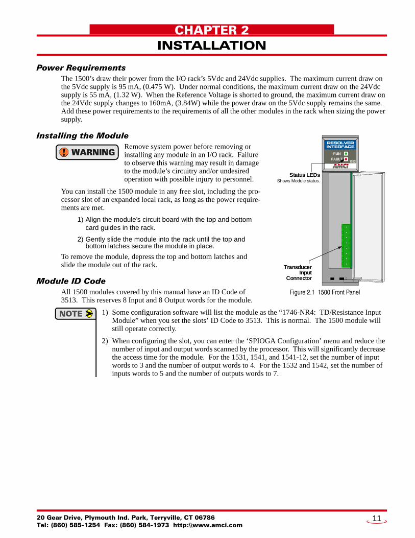
Installing the ModuleRemove system power before removing or installing any module in an I/O rack. Failure to observe this warning may result in damage to the module’s circuitry and/or undesired operation with possible injury to personnel.
You can install the 1500 module in any free slot, including the pro-cessor slot of an expanded local rack, as long as the power require-ments are met.
1) Align the module’s circuit board with the top and bottom card guides in the rack.
2) Gently slide the module into the rack until the top and bottom latches secure the module in place.
To remove the module, depress the top and bottom latches and slide the module out of the rack.
Module ID CodeAll 1500 modules covered by this manual have an ID Code of 3513. This reserves 8 Input and 8 Output words for the module.
1) Some configuration software will list the module as the “1746-NR4: TD/Resistance Input Module” when you set the slots’ ID Code to 3513. This is normal. The 1500 module will still operate correctly.
2) When configuring the slot, you can enter the ‘SPIOGA Configuration’ menu and reduce the number of input and output words scanned by the processor. This will significantly decrease the access time for the module. For the 1531, 1541, and 1541-12, set the number of input words to 3 and the number of output words to 4. For the 1532 and 1542, set the number of inputs words to 5 and the number of outputs words to 7.
TransducerInput
Connector
Status LEDs Shows Module status.
RESOLVERINTERFACE
1532
Figure 2.1 1500 Front Panel
. Park, Terryville, CT 0678660) 584-1973 http:\\www.amci.com
11
INSTALLATION2
Status LED’sAs shown in figure 2.1 on the previous page, the front panel has two Status LED’s, RUN and FAULT. Once power is applied, these two LED’s indicate the operating status of the module. Table 2.1 below shows the pat-terns that may appear on the LED’s and their meaning.
Table 2.1 Status LED’s
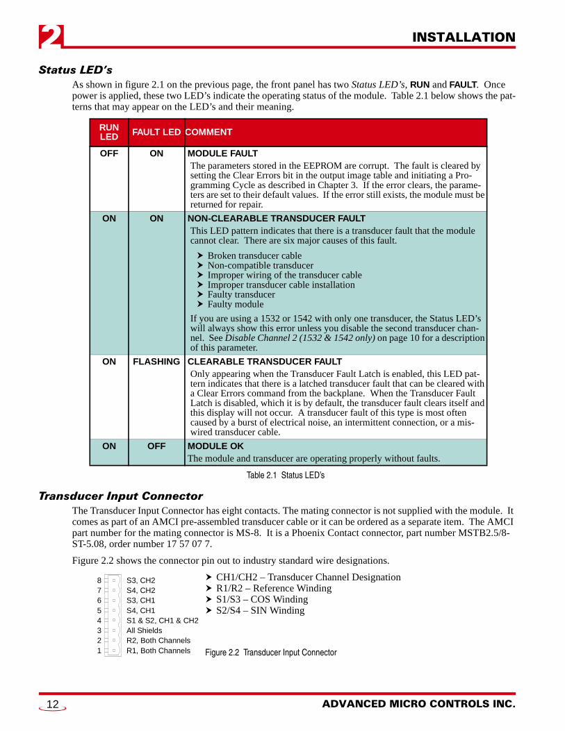
Transducer Input ConnectorThe Transducer Input Connector has eight contacts. The mating connector is not supplied with the module. It comes as part of an AMCI pre-assembled transducer cable or it can be ordered as a separate item. The AMCI part number for the mating connector is MS-8. It is a Phoenix Contact connector, part number MSTB2.5/8-ST-5.08, order number 17 57 07 7.
Figure 2.2 shows the connector pin out to industry standard wire designations.
CH1/CH2 – Transducer Channel DesignationR1/R2 – Reference WindingS1/S3 – COS WindingS2/S4 – SIN Winding
Figure 2.2 Transducer Input Connector
RUN LED FAULT LED COMMENT
OFF ON MODULE FAULTThe parameters stored in the EEPROM are corrupt. The fault is cleared by setting the Clear Errors bit in the output image table and initiating a Pro-gramming Cycle as described in Chapter 3. If the error clears, the parame-ters are set to their default values. If the error still exists, the module must be returned for repair.
ON ON NON-CLEARABLE TRANSDUCER FAULTThis LED pattern indicates that there is a transducer fault that the module cannot clear. There are six major causes of this fault.
Broken transducer cableNon-compatible transducerImproper wiring of the transducer cableImproper transducer cable installationFaulty transducerFaulty module
If you are using a 1532 or 1542 with only one transducer, the Status LED’s will always show this error unless you disable the second transducer chan-nel. See Disable Channel 2 (1532 & 1542 only) on page 10 for a description of this parameter.
ON FLASHING CLEARABLE TRANSDUCER FAULTOnly appearing when the Transducer Fault Latch is enabled, this LED pat-tern indicates that there is a latched transducer fault that can be cleared with a Clear Errors command from the backplane. When the Transducer Fault Latch is disabled, which it is by default, the transducer fault clears itself and this display will not occur. A transducer fault of this type is most often caused by a burst of electrical noise, an intermittent connection, or a mis-wired transducer cable.
ON OFF MODULE OKThe module and transducer are operating properly without faults.
87654321
S3, CH2S4, CH2S3, CH1S4, CH1S1 & S2, CH1 & CH2All ShieldsR2, Both ChannelsR1, Both Channels
ADVANCED MICRO CONTROLS INC.12
INSTALLATION 2
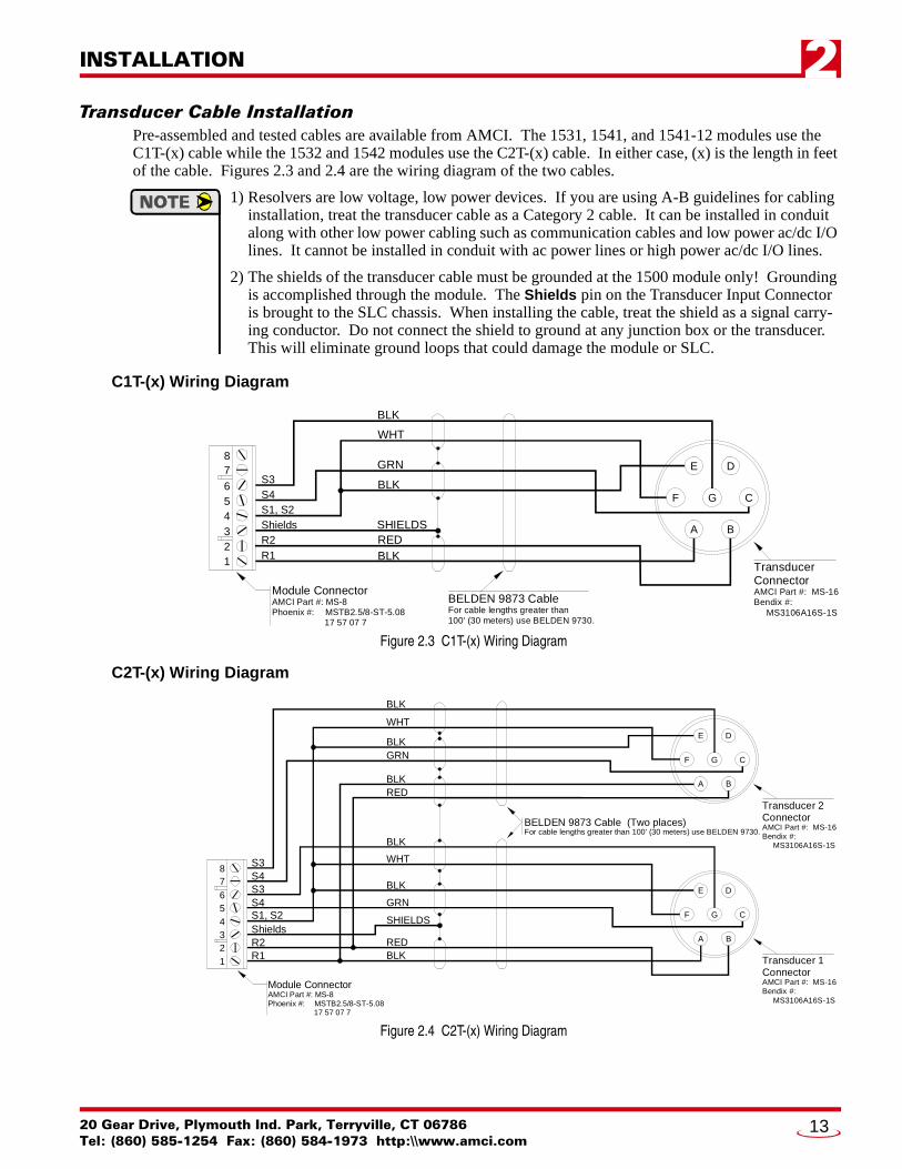
Transducer Cable InstallationPre-assembled and tested cables are available from AMCI. The 1531, 1541, and 1541-12 modules use the C1T-(x) cable while the 1532 and 1542 modules use the C2T-(x) cable. In either case, (x) is the length in feet of the cable. Figures 2.3 and 2.4 are the wiring diagram of the two cables.
1) Resolvers are low voltage, low power devices. If you are using A-B guidelines for cabling installation, treat the transducer cable as a Category 2 cable. It can be installed in conduit along with other low power cabling such as communication cables and low power ac/dc I/O lines. It cannot be installed in conduit with ac power lines or high power ac/dc I/O lines.
2) The shields of the transducer cable must be grounded at the 1500 module only! Grounding is accomplished through the module. The Shields pin on the Transducer Input Connector is brought to the SLC chassis. When installing the cable, treat the shield as a signal carry-ing conductor. Do not connect the shield to ground at any junction box or the transducer. This will eliminate ground loops that could damage the module or SLC.
C1T-(x) Wiring Diagram
Figure 2.3 C1T-(x) Wiring Diagram
C2T-(x) Wiring Diagram
Figure 2.4 C2T-(x) Wiring Diagram
A B
C
DE
F G
BLK
WHT
GRN
BLK
SHIELDSREDBLK
BELDEN 9873 CableFor cable lengths greater than100' (30 meters) use BELDEN 9730.
Module ConnectorAMCI Part #: MS-8Phoenix #: MSTB2.5/8-ST-5.08 17 57 07 7
S3S4S1, S2ShieldsR2R1
87
654321 Transducer
ConnectorAMCI Part #: MS-16Bendix #: MS3106A16S-1S
A B
C
DE
F G
BLK
WHT
GRN
BLK
SHIELDS
REDBLK
BELDEN 9873 Cable (Two places)For cable lengths greater than 100' (30 meters) use BELDEN 9730.
BLK
WHT
GRNBLK
REDBLK
R1
87654321
R2ShieldsS1, S2S4S3S4S3
A B
C
DE
F G
Module ConnectorAMCI Part #: MS-8Phoenix #: MSTB2.5/8-ST-5.08 17 57 07 7
Transducer 2Connector AMCI Part #: MS-16Bendix #: MS3106A16S-1S
Transducer 1Connector AMCI Part #: MS-16Bendix #: MS3106A16S-1S
20 Gear Drive, Plymouth Ind. Park, Terryville, CT 06786Tel: (860) 585-1254 Fax: (860) 584-1973 http:\\www.amci.com
13
INSTALLATION2
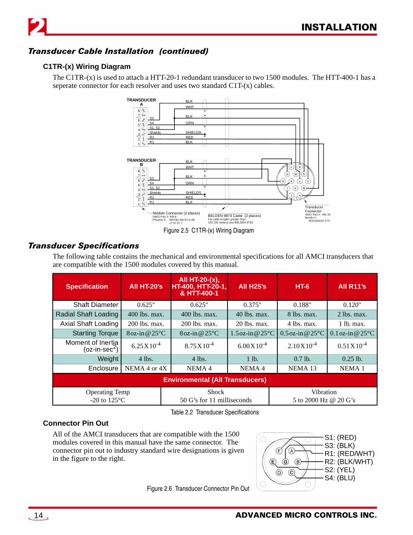
Transducer Cable Installation (continued)C1TR-(x) Wiring DiagramThe C1TR-(x) is used to attach a HTT-20-1 redundant transducer to two 1500 modules. The HTT-400-1 has a seperate connector for each resolver and uses two standard C1T-(x) cables.
Figure 2.5 C1TR-(x) Wiring Diagram
Transducer SpecificationsThe following table contains the mechanical and environmental specifications for all AMCI transducers that are compatible with the 1500 modules covered by this manual.
Table 2.2 Transducer Specifications
Connector Pin OutAll of the AMCI transducers that are compatible with the 1500 modules covered in this manual have the same connector. The connector pin out to industry standard wire designations is given in the figure to the right.
Figure 2.6 Transducer Connector Pin Out
Specification All HT-20’sAll HT-20-(x),
HT-400, HTT-20-1,& HTT-400-1
All H25’s HT-6 All R11’s
Shaft Diameter 0.625" 0.625" 0.375" 0.188" 0.120"
Radial Shaft Loading 400 lbs. max. 400 lbs. max. 40 lbs. max. 8 lbs. max. 2 lbs. max.
Axial Shaft Loading 200 lbs. max. 200 lbs. max. 20 lbs. max. 4 lbs. max. 1 lb. max.
Starting Torque 8oz-in@25°C 8oz-in@25°C 1.5oz-in@25°C 0.5oz-in@25°C 0.1oz-in@25°C
Moment of Inertia(oz-in-sec2) 6.25X10⁻⁴ 8.75X10⁻⁴ 6.00X10⁻⁴ 2.10X10⁻⁴ 0.51X10⁻⁴
Weight 4 lbs. 4 lbs. 1 lb. 0.7 lb. 0.25 lb.
Enclosure NEMA 4 or 4X NEMA 4 NEMA 4 NEMA 13 NEMA 1
Environmental (All Transducers)
Operating Temp-20 to 125°C
Shock50 G’s for 11 milliseconds
Vibration5 to 2000 Hz @ 20 G’s
BLK
WHT
GRN
BLK
SHIELDSREDBLK
BELDEN 9873 Cable (2 places)For cable lengths greater than100' (30 meters) use BELDEN 9730.
Module Connector (2 places)AMCI Part #: MS-8Phoenix #: MSTB2.5/8-ST-5.08 17 57 07 7
S3S4S1, S2ShieldsR2R1
87
654321
A
N
B
C
D
EF
G
H
I
J
K
L
M
TransducerConnector AMCI Part #: MS-20Bendix #: MS3106A20-27S
BLK
WHT
GRN
BLK
SHIELDSREDBLK
S3S4S1, S2ShieldsR2R1
87
654321
TRANSDUCERB
TRANSDUCERA
S1: (RED)S3: (BLK)R1: (RED/WHT)R2: (BLK/WHT)S2: (YEL)S4: (BLU)
ADVANCED MICRO CONTROLS INC.14

INSTALLATION 2
AMCI Transducer MountingAll AMCI resolver based transducers are designed to operate in the industrial environment and therefore require little attention. However, there are some general guidelines that should be observed to ensure long life.
Limit transducer shaft loading to the following maximums:
Table 2.3 Transducer Bearing Loads
Minimize shaft misalignment when direct coupling shafts. Even small misalignments produce large loading effects on front bearings. It is recommended that you use a flexible coupler whenever possible. A flexible coupler is required for all HT-6 transducers and R11 resolvers.
AMCI Transducer Outline DrawingsAMCI offers a broad line of resolver based transducers for use with the 1500 modules. (See AMCI Compati-ble Transducers on page 7.) Outline drawings for all of these transducers, and full spec sheets for our most popular transducers, are available on our website, www.amci.com. If you do not have internet access, contact AMCI and we will fax the information to you.
Autotech Transducer Installation
Autotech Transducer MountingThe series 1500 modules covered by this manual support Autotech SAC-RL100, E6R and E7R-RL101, SAC-RL101-010, and SAC-RL220 transducers. Refer to Autotech Controls literature for dimensional drawings and mounting recommendations.
Even though Autotech transducers are usable, we strongly recommend using AMCI transducers whenever possible. Refer to the Autotech / AMCI Transducer Cross Reference table on page 8 for information on our recommended replacements for Autotech transducers.
Radial Load Axial Load
All 0.625" Shafts 100 lbs. (445 N) 50 lbs. (222 N)
All 0.375" Shafts 30 lbs. (133 N) 15 lbs. (66.7 N)
All Other Shafts 1 lb. (4.45 N) 0.5 lb. (2.22 N)
20 Gear Drive, Plymouth Ind. Park, Terryville, CT 06786Tel: (860) 585-1254 Fax: (860) 584-1973 http:\\www.amci.com
15
INSTALLATION2
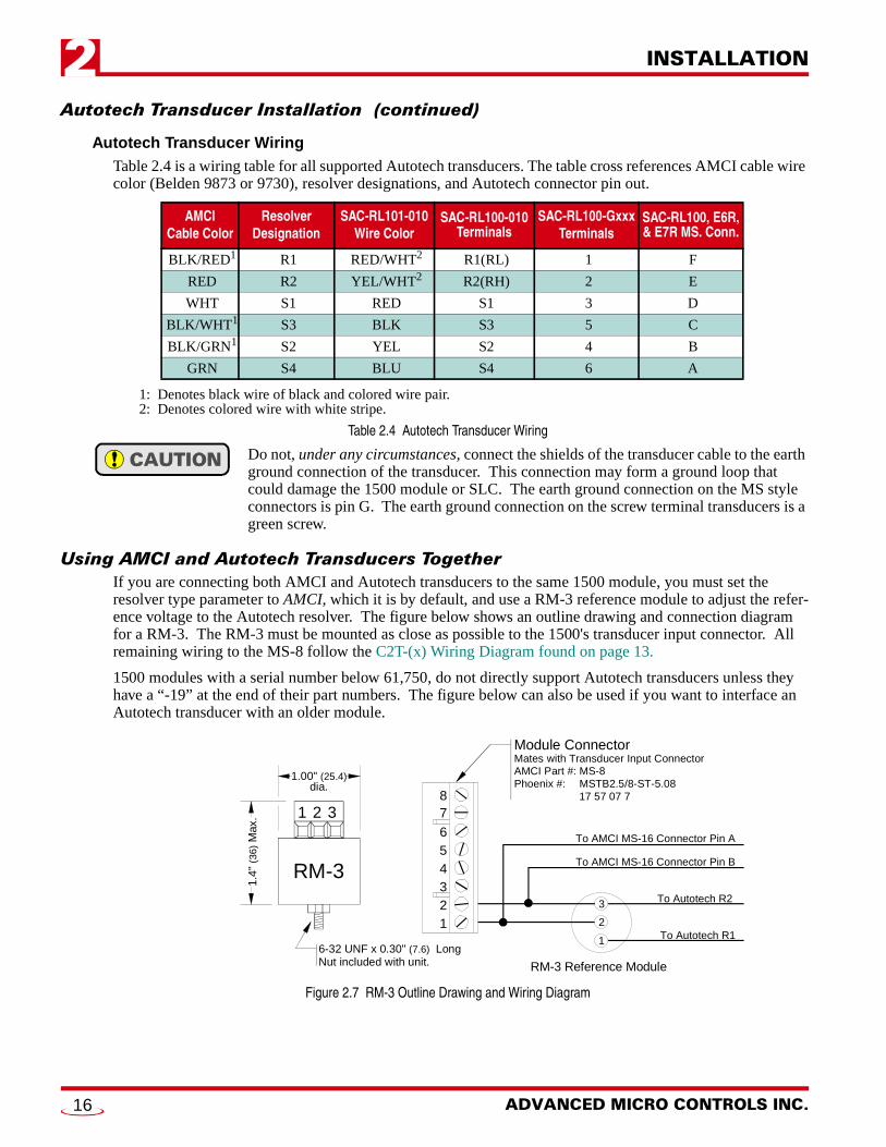
Autotech Transducer Installation (continued)Autotech Transducer WiringTable 2.4 is a wiring table for all supported Autotech transducers. The table cross references AMCI cable wire color (Belden 9873 or 9730), resolver designations, and Autotech connector pin out.
1: Denotes black wire of black and colored wire pair.2: Denotes colored wire with white stripe.
Table 2.4 Autotech Transducer Wiring
Do not, under any circumstances, connect the shields of the transducer cable to the earth ground connection of the transducer. This connection may form a ground loop that could damage the 1500 module or SLC. The earth ground connection on the MS style connectors is pin G. The earth ground connection on the screw terminal transducers is a green screw.
Using AMCI and Autotech Transducers TogetherIf you are connecting both AMCI and Autotech transducers to the same 1500 module, you must set the resolver type parameter to AMCI, which it is by default, and use a RM-3 reference module to adjust the refer-ence voltage to the Autotech resolver. The figure below shows an outline drawing and connection diagram for a RM-3. The RM-3 must be mounted as close as possible to the 1500's transducer input connector. All remaining wiring to the MS-8 follow the C2T-(x) Wiring Diagram found on page 13.
1500 modules with a serial number below 61,750, do not directly support Autotech transducers unless they have a “-19” at the end of their part numbers. The figure below can also be used if you want to interface an Autotech transducer with an older module.
Figure 2.7 RM-3 Outline Drawing and Wiring Diagram
AMCICable Color
ResolverDesignation
SAC-RL101-010Wire Color
SAC-RL100-010 Terminals
SAC-RL100-GxxxTerminals
SAC-RL100, E6R, & E7R MS. Conn.
BLK/RED1 R1 RED/WHT2 R1(RL) 1 F
RED R2 YEL/WHT2 R2(RH) 2 E
WHT S1 RED S1 3 D
BLK/WHT1 S3 BLK S3 5 C
BLK/GRN1 S2 YEL S2 4 B
GRN S4 BLU S4 6 A
1 2 3
RM-3
1.4"
(36)
Max
.
6-32 UNF x 0.30" (7.6) LongNut included with unit.
87
654321
1
2
3
Module ConnectorMates with Transducer Input ConnectorAMCI Part #: MS-8Phoenix #: MSTB2.5/8-ST-5.08 17 57 07 7
To Autotech R2
To Autotech R1
RM-3 Reference Module
To AMCI MS-16 Connector Pin A
To AMCI MS-16 Connector Pin B
1.00" (25.4)dia.
ADVANCED MICRO CONTROLS INC.16
20 Gear Drive, Plymouth IndTel: (860) 585-1254 Fax: (8
CHAPTER 3
BACKPLANE PROGRAMMINGData AddressingData address are defined in the following manner.
I:X.n Input Image TableO:X.n Output Image Table
Where ‘X’ is the slot number of the 1500 and ‘n’ is the word number in the data block. When referring to a specific bit in a word, the characters “/bb” will be appended to the file address where ‘bb’ is the bit address.
Programming CycleProgramming changes are written to the module with a Programming Cycle. All programmable parameters can be changed, and the position value preset, with a single programming cycle. Programming cycles are controlled with the Transmit Bit and Acknowledge Bit.
1) Write the new programming data into the output image table with the Transmit Bit reset. This step insures that the correct data is in the output image table before the Programming Cycle begins.
2) Set the Transmit bit. A Programming Cycle is initiated when this bit makes a 0 1 transition.
3) Once the 1500 is done with the programming data, it will set any necessary error bits and the Acknowledge Bit in the input image table.
4) Check for errors once the Acknowledge bit makes a 0 1 transition. The error bits are only valid while the Acknowledge Bit is set.
5) Respond to any errors and reset the Transmit Bit.
6) The module responds by resetting the Acknowledge Bit. The Programming Cycle is complete.
If the module encounters an error, it will set the appropriate error bit in Input Word 0 and stop processing the data. All of your data must be correct before the 1500 accepts any changes.
The EEPROM used to store parameter values, and the internal offset that is calculated every time you preset the position, is guaranteed for approximately 100,000 write cycles before writing to it will cause it to fail. Therefore, continuously presetting the position or writing new parameters should be avoided. If your application requires you to contin-uously preset the position, consider calculating the required position offset in you ladder logic program. A ladder logic segment that accomplishes this is shown at the end of the manual. See Offsetting the Transducer Position in the SLC on page 25.
Guidelines for Programming an Older ModuleIf your module has a serial number below 61,750, then the new features that were incorporated into the mod-ule with the release of hardware rev. E are not available on your module. You can use the programming instructions in this chapter as long as you adhere to the following guidelines.
1) Programming bits in the output image table associated with the new features must remain reset during a Programming Cycle. If any of these bits are set, the module responds by setting the Message Ignored bit and does not process the programming data.
2) If you using a 1541, 1542, or 1541-12, the maximum Scale Factor value is 5,000, not 8,192.
3) The two bits in the output image table that are used to apply the Preset Value (I:X.0/00 and I:X.0/01) can still be used. However the position can only be reset to zero because the older modules do not support the Preset Value parameter.
A 1500 module communicates with the SLC processor through the input and output image tables.The input image table is used to transmit Status, Position, and Tachometer data to the processor.The output image table is used to setup the 1500 module as well as preset the position value andclear latched transducer faults. This chapter details the data format of the input and output imagetables and how to program the 1500 module.
. Park, Terryville, CT 0678660) 584-1973 http:\\www.amci.com
17
BACKPLANE PROGRAMMING3
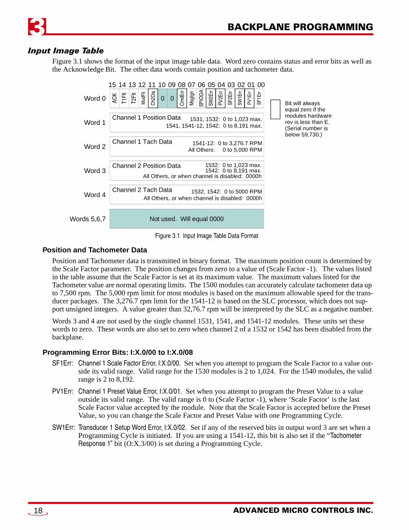
Input Image TableFigure 3.1 shows the format of the input image table data. Word zero contains status and error bits as well as the Acknowledge Bit. The other data words contain position and tachometer data.
Figure 3.1 Input Image Table Data Format
Position and Tachometer DataPosition and Tachometer data is transmitted in binary format. The maximum position count is determined by the Scale Factor parameter. The position changes from zero to a value of (Scale Factor -1). The values listed in the table assume that the Scale Factor is set at its maximum value. The maximum values listed for the Tachometer value are normal operating limits. The 1500 modules can accurately calculate tachometer data up to 7,500 rpm. The 5,000 rpm limit for most modules is based on the maximum allowable speed for the trans-ducer packages. The 3,276.7 rpm limit for the 1541-12 is based on the SLC processor, which does not sup-port unsigned integers. A value greater than 32,76.7 rpm will be interpreted by the SLC as a negative number.
Words 3 and 4 are not used by the single channel 1531, 1541, and 1541-12 modules. These units set these words to zero. These words are also set to zero when channel 2 of a 1532 or 1542 has been disabled from the backplane.
Programming Error Bits: I:X.0/00 to I:X.0/08SF1Err: Channel 1 Scale Factor Error, I:X.0/00. Set when you attempt to program the Scale Factor to a value out-
side its valid range. Valid range for the 1530 modules is 2 to 1,024. For the 1540 modules, the valid range is 2 to 8,192.
PV1Err: Channel 1 Preset Value Error, I:X.0/01. Set when you attempt to program the Preset Value to a value outside its valid range. The valid range is 0 to (Scale Factor -1), where ‘Scale Factor’ is the last Scale Factor value accepted by the module. Note that the Scale Factor is accepted before the Preset Value, so you can change the Scale Factor and Preset Value with one Programming Cycle.
SW1Err: Transducer 1 Setup Word Error, I:X.0/02. Set if any of the reserved bits in output word 3 are set when a Programming Cycle is initiated. If you are using a 1541-12, this bit is also set if the “Tachometer Response 1” bit (O:X.3/00) is set during a Programming Cycle.
15 14 13 12 11 10 09 08 07 06 05 04 03 02 01 00
ACK
Channel 1 Tach Data
Word 0
Word 1
Word 2
Word 3
Word 4
Not used. Will equal 0000Words 5,6,7
SF2E
rr
SW2E
rr
Msg
Ign
SF1E
rr
Mod
Flt
Cm
dErr
T1Fl
t
T2Fl
t
Ch2
Dis
PV2E
rr
PV1E
rr
SW1E
rr
SPIO
GA
00
1541-12: 0 to 3,276.7 RPMAll Others: 0 to 5,000 RPM
Channel 1 Position Data 1531, 1532: 0 to 1,023 max.1541, 1541-12, 1542: 0 to 8,191 max.
Channel 2 Position Data 1532: 0 to 1,023 max.1542: 0 to 8,191 max.
All Others, or when channel is disabled: 0000h
Channel 2 Tach Data 1532, 1542: 0 to 5000 RPMAll Others, or when channel is disabled: 0000h
Bit will alwaysequal zero if themodules hardwarerev is less than E.(Serial number is below 59,730.)
ADVANCED MICRO CONTROLS INC.18
BACKPLANE PROGRAMMING 3
Input Image Table (continued)Programming Error Bits: I:X.0/00 to I:X.0/08 (continued)
SF2Err: Channel 2 Scale Factor Error, I:X.0/03. Set when you attempt to program the Scale Factor to a value out-side its valid range. Valid range for the 1532 module is 2 to 1,024. For the 1542 module, the valid range is 2 to 8,192.
PV2Err: Channel 2 Preset Value Error, I:X.0/04. Set when you attempt to program the Preset Value to a value outside its valid range. The valid range is 0 to (Scale Factor -1), where ‘Scale Factor’ is the last Scale Factor value accepted by the module. Note that the Scale Factor is accepted before the Preset Value, so you can change the Scale Factor and Preset Value with one Programming Cycle.
SW2Err: Channel 2 Setup Word Error, I:X.0/05. Set if any of the reserved bits in output word 6 are set when a Programming Cycle is initiated.
SPIOGA: SPIOGA Error, I:X.0/06. Set when there is a communications error between the processor and the mod-ules’ SPIOGA backplane interface IC.
MsgIgn: Message Ignored, I:X.0/07. Set under the following conditions:1) Your ladder logic attempts to program the module while an EEPROM error exists.
2) No Command bits are set when a Programming Cycle was initiated. Command bits are in word zero. (O:X.0/00-09)
3) If one of the Programming Error bits in input word zero is set, (I:X.0/00-05), the error must be cleared by re-programming the incorrect parameter or using the Clear Errors bit (O:X.0/13). This bit is set if you attempt to program a different parameter before correcting the error on the first.
CmdErr: Command Error, I:X.0/08. Set under the following conditions:1) One or more of the reserved bits in output word zero, O:X.0/10-12, are set when a Programming Cycle is
initiated.
2) The Resolver Type bit, (O:X.0/09) is set and the Program Resolver Type bit (O:X.0/08) is reset when a Programming Cycle is initiated.
3) If you are using a 1531, 1541, or 1541-12 and one or more of the bits used to program channel 2, (O:X.0/01,05-07) are set when a Programming Cycle is initiated.
Status Bits: I:X.0/11 to I:X.0/14C2Dis: Channel 2 Disabled, I:X.0/11. Set when channel two of a 1532 or 1542 has been disabled from the
backplane. When disabled, the module sets the Position and Tachometer data for channel 2 to zero and will leave the transducer 2 fault bit (I:X.0/13) reset.
ModFlt: Module Fault, I:X.0/12. Set when there is an EEPROM memory error or other hardware fault. If this bit is set, initiate a Programming Cycle with the Clear Module Fault bit, (O:X.0/14) set. If the error does not clear, contact AMCI for assistance. If it does clear, all parameters will be reset to their default values.
T2Flt: Transducer 2 Fault, I:X.0/13. Set when there is a non-clearable transducer fault on channel 2 or when a transient fault has occurred and the Transducer 2 Fault Latch is enabled.
T1Flt: Transducer 1 Fault, I:X.0/14. Set when there is a non-clearable transducer fault on channel 1or when a transient fault has occurred and the Transducer 1 Fault Latch is enabled.
Acknowledge Bit: I:X.0/15ACK: Acknowledge Bit, I:X.0/15. Set by the module to acknowledge programming data from the processor.
Programming Error Bits in input word zero, (I:X.0/00-08), are valid only while this bit is set. Status Bits, (I:X.0/11-14), are always valid. The module reset the Acknowledge Bit after the processor resets the Transmit Bit.
20 Gear Drive, Plymouth Ind. Park, Terryville, CT 06786Tel: (860) 585-1254 Fax: (860) 584-1973 http:\\www.amci.com
19
BACKPLANE PROGRAMMING3
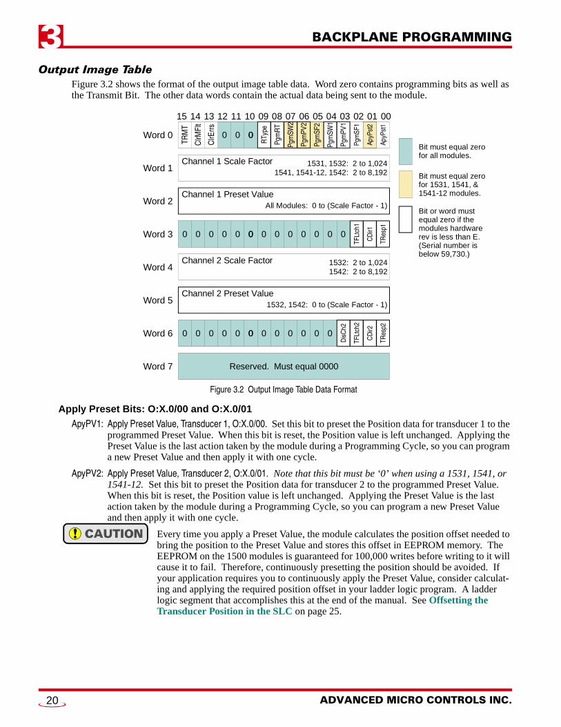
Output Image TableFigure 3.2 shows the format of the output image table data. Word zero contains programming bits as well as the Transmit Bit. The other data words contain the actual data being sent to the module.
Figure 3.2 Output Image Table Data Format
Apply Preset Bits: O:X.0/00 and O:X.0/01ApyPV1: Apply Preset Value, Transducer 1, O:X.0/00. Set this bit to preset the Position data for transducer 1 to the
programmed Preset Value. When this bit is reset, the Position value is left unchanged. Applying the Preset Value is the last action taken by the module during a Programming Cycle, so you can program a new Preset Value and then apply it with one cycle.
ApyPV2: Apply Preset Value, Transducer 2, O:X.0/01. Note that this bit must be ‘0’ when using a 1531, 1541, or 1541-12. Set this bit to preset the Position data for transducer 2 to the programmed Preset Value. When this bit is reset, the Position value is left unchanged. Applying the Preset Value is the last action taken by the module during a Programming Cycle, so you can program a new Preset Value and then apply it with one cycle.
Every time you apply a Preset Value, the module calculates the position offset needed to bring the position to the Preset Value and stores this offset in EEPROM memory. The EEPROM on the 1500 modules is guaranteed for 100,000 writes before writing to it will cause it to fail. Therefore, continuously presetting the position should be avoided. If your application requires you to continuously apply the Preset Value, consider calculat-ing and applying the required position offset in your ladder logic program. A ladder logic segment that accomplishes this at the end of the manual. See Offsetting the Transducer Position in the SLC on page 25.
15 14 13 12 11 10 09 08 07 06 05 04 03 02 01 00
TRM
TChannel 1 Preset Value
Word 0
Word 1
Word 2
Reserved. Must equal 0000Word 7
Pgm
PV1
Pgm
SF2
Pgm
SW2
ApyP
st1
Pgm
RT
ClrM
Flt
ClrE
rrs
Pgm
SW1
ApyP
st2
Pgm
SF1
Pgm
PV2
0
All Modules: 0 to (Scale Factor - 1)
Channel 1 Scale Factor 1531, 1532: 2 to 1,0241541, 1541-12, 1542: 2 to 8,192
00
RTy
pe
0
Channel 2 Preset Value
Word 4
Word 5 1532, 1542: 0 to (Scale Factor - 1)
Channel 2 Scale Factor 1532: 2 to 1,0241542: 2 to 8,192
Word 3
TRes
p1
CDi
r1
TFLt
ch1
0000 0 0 0 0 0 0 0000
Word 6
TRes
p2
CDi
r2
TFLt
ch2
0000 0 0 0 0 0 0000D
isCh2
Bit must equal zerofor all modules.
Bit must equal zerofor 1531, 1541, &1541-12 modules.
Bit or word mustequal zero if themodules hardwarerev is less than E.(Serial number is below 59,730.)
ADVANCED MICRO CONTROLS INC.20
BACKPLANE PROGRAMMING 3
Output Image Table (continued)Program Bits: O:X.0/02 to O:X.0/09Program Bits O:X.0/02 through O:X.0/07 control when the programming data in output words O:X.1 through O:X.6 is acted upon. If a bit is reset when a Programming Cycle is initiated, the data in the corresponding word is ignored. Likewise, the PgmRT bit (O:X.0/08) controls when the state of the RType bit (O:X.0/09) is used to program the Resolver Type.
PgmSF1: Program Scale Factor 1, O:X.0/02. Set this bit to program the Scale Factor parameter for transducer 1. The new Scale Factor value is stored in word 1 and must be in binary.
PgmPV1: Program Preset Value 1, O:X.0/03. Set this bit to program the Preset Value parameter for transducer 1. The new Preset Value is stored in word 2 and must be in binary. Note that programming the Preset Value does not change the position count. To change the position to your Preset Value, set the Apply Preset Value, Transducer 1 bit (O:X.0/00) before initiating a Programming Cycle.
PgmSW1: Program Setup Word 1, O:X.0/04. Set this bit to program all of the parameters for transducer 1 that are contained in output word 3. These parameters are Tach Response 1, Count Direction 1, and Trans-ducer Fault Latch 1. These three parameters are programmed as a group and cannot be programmed individually.
PgmSF2: Program Scale Factor 2, O:X.0/05. Note that this bit must be ‘0’ when using a 1531, 1541, or 1541-12. Set this bit to program the Scale Factor parameter for transducer 2. The new Scale Factor value is stored in word 4 and must be in binary format.
PgmPV2: Program Preset Value 2, O:X.0/06. Note that this bit must be ‘0’ when using a 1531, 1541, or 1541-12. Set this bit to program the Preset Value parameter for transducer 2. The new Preset Value is stored in word 5 and must be in binary format. Note that programming the Preset Value does not change the position count. To change the position to your Preset Value, set the Apply Preset Value, Transducer 2 bit (O:X.0/01) before initiating a Programming Cycle.
PgmSW2: Program Setup Word 2, O:X.0/07. Note that this bit must be ‘0’ when using a 1531, 1541, or 1541-12. Set this bit to program all of the parameters for transducer 2 that are contained in output word 6. These four parameters are Tach Response 2, Count Direction 2, Transducer Fault Latch 2, and Dis-able Channel 2. These four parameters are programmed as a group and cannot be programmed indi-vidually.
PgmRT: Program Resolver Type, O:X.0/08. Set this bit to program the Resolver Type parameter to the value specified by the Resolver Type bit (O:X.0/09). When this bit is reset, the Resolver Type parameter is not programmed and the Resolver Type bit must be reset.
RType: Resolver Type, O:X.0/09. Reset this bit to program the Resolver Type parameter to AMCI. Set this bit to program the Resolver Type for Autotech Controls transducers. This bit is only acted upon when the PgmRT bit (O:X.0/08) is set. If the PgmRT bit is reset, this bit must also be reset.
Command Bits: O:X.0/13 and O:X.0/14ClrErrs: Clear Errors, O:X.0/13. Set this bit to clear programming errors and latched transducer faults. This
one bit is used to clear transducer faults on both channels of a 1532 or 1542. If a transducer fault still exists after a Programming Cycle that had this bit set, the transducer fault is non-clearable and user intervention is required to fix the fault.
ClrMFlt: Clear Module Fault, O:X.0/14. Set this bit to clear a module fault. If the module fault still exists after a Programming Cycle that had this bit set, contact AMCI for assistance. See the Inside Front Cover for information on contacting AMCI. If the fault does clear, the module reset all parameters back to their factory defaults. Setting this bit has no affect if a module fault does not exist.
20 Gear Drive, Plymouth Ind. Park, Terryville, CT 06786Tel: (860) 585-1254 Fax: (860) 584-1973 http:\\www.amci.com
21
BACKPLANE PROGRAMMING3
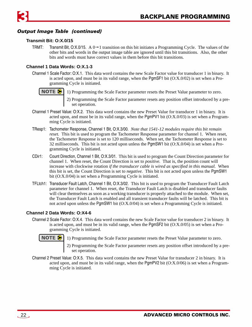
Output Image Table (continued)Transmit Bit: O:X.0/15TRMT: Transmit Bit, O:X.0/15. A 0 1 transition on this bit initiates a Programming Cycle. The values of the
other bits and words in the output image table are ignored until this bit transitions. Also, the other bits and words must have correct values in them before this bit transitions.
Channel 1 Data Words: O:X.1-3Channel 1 Scale Factor: O:X.1. This data word contains the new Scale Factor value for transducer 1 in binary. It
is acted upon, and must be in its valid range, when the PgmSF1 bit (O:X.0/02) is set when a Pro-gramming Cycle is initiated.
1) Programming the Scale Factor parameter resets the Preset Value parameter to zero.
2) Programming the Scale Factor parameter resets any position offset introduced by a pre-set operation.
Channel 1 Preset Value: O:X.2. This data word contains the new Preset Value for transducer 1 in binary. It is acted upon, and must be in its valid range, when the PgmPV1 bit (O:X.0/03) is set when a Program-ming Cycle is initiated.
TResp1: Tachometer Response, Channel 1 Bit, O:X.3/00. Note that 1541-12 modules require this bit remain reset. This bit is used to program the Tachometer Response parameter for channel 1. When reset, the Tachometer Response is set to 120 milliseconds. When set, the Tachometer Response is set to 32 milliseconds. This bit is not acted upon unless the PgmSW1 bit (O:X.0/04) is set when a Pro-gramming Cycle is initiated.
CDir1: Count Direction, Channel 1 Bit, O:X.3/01. This bit is used to program the Count Direction parameter for channel 1. When reset, the Count Direction is set to positive. That is, the position count will increase with clockwise rotation if the transducer cable is wired as specified in this manual. When this bit is set, the Count Direction is set to negative. This bit is not acted upon unless the PgmSW1 bit (O:X.0/04) is set when a Programming Cycle is initiated.
TFLtch1: Transducer Fault Latch, Channel 1 Bit, O:X.3/02. This bit is used to program the Transducer Fault Latch parameter for channel 1. When reset, the Transducer Fault Latch is disabled and transducer faults will clear themselves as soon as a working transducer is properly attached to the module. When set, the Transducer Fault Latch is enabled and all transient transducer faults will be latched. This bit is not acted upon unless the PgmSW1 bit (O:X.0/04) is set when a Programming Cycle is initiated.
Channel 2 Data Words: O:X4-6Channel 2 Scale Factor: O:X.4. This data word contains the new Scale Factor value for transducer 2 in binary. It
is acted upon, and must be in its valid range, when the PgmSF2 bit (O:X.0/05) is set when a Pro-gramming Cycle is initiated.
1) Programming the Scale Factor parameter resets the Preset Value parameter to zero.
2) Programming the Scale Factor parameter resets any position offset introduced by a pre-set operation.
Channel 2 Preset Value: O:X.5. This data word contains the new Preset Value for transducer 2 in binary. It is acted upon, and must be in its valid range, when the PgmPV2 bit (O:X.0/06) is set when a Program-ming Cycle is initiated.
ADVANCED MICRO CONTROLS INC.22
BACKPLANE PROGRAMMING 3
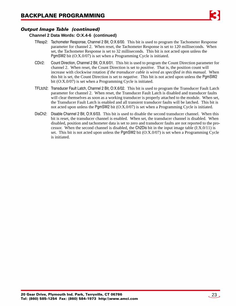
Output Image Table (continued)Channel 2 Data Words: O:X.4-6 (continued)
TResp2: Tachometer Response, Channel 2 Bit, O:X.6/00. This bit is used to program the Tachometer Response parameter for channel 2. When reset, the Tachometer Response is set to 120 milliseconds. When set, the Tachometer Response is set to 32 milliseconds. This bit is not acted upon unless the PgmSW2 bit (O:X.0/07) is set when a Programming Cycle is initiated.
CDir2: Count Direction, Channel 2 Bit, O:X.6/01. This bit is used to program the Count Direction parameter for channel 2. When reset, the Count Direction is set to positive. That is, the position count will increase with clockwise rotation if the transducer cable is wired as specified in this manual. When this bit is set, the Count Direction is set to negative. This bit is not acted upon unless the PgmSW2 bit (O:X.0/07) is set when a Programming Cycle is initiated.
TFLtch2: Transducer Fault Latch, Channel 2 Bit, O:X.6/02. This bit is used to program the Transducer Fault Latch parameter for channel 2. When reset, the Transducer Fault Latch is disabled and transducer faults will clear themselves as soon as a working transducer is properly attached to the module. When set, the Transducer Fault Latch is enabled and all transient transducer faults will be latched. This bit is not acted upon unless the PgmSW2 bit (O:X.0/07) is set when a Programming Cycle is initiated.
DisCh2: Disable Channel 2 Bit, O:X.6/03. This bit is used to disable the second transducer channel. When this bit is reset, the transducer channel is enabled. When set, the transducer channel is disabled. When disabled, position and tachometer data is set to zero and transducer faults are not reported to the pro-cessor. When the second channel is disabled, the Ch2Dis bit in the input image table (I:X.0/11) is set. This bit is not acted upon unless the PgmSW2 bit (O:X.0/07) is set when a Programming Cycle is initiated.
20 Gear Drive, Plymouth Ind. Park, Terryville, CT 06786Tel: (860) 585-1254 Fax: (860) 584-1973 http:\\www.amci.com
23
BACKPLANE PROGRAMMING3
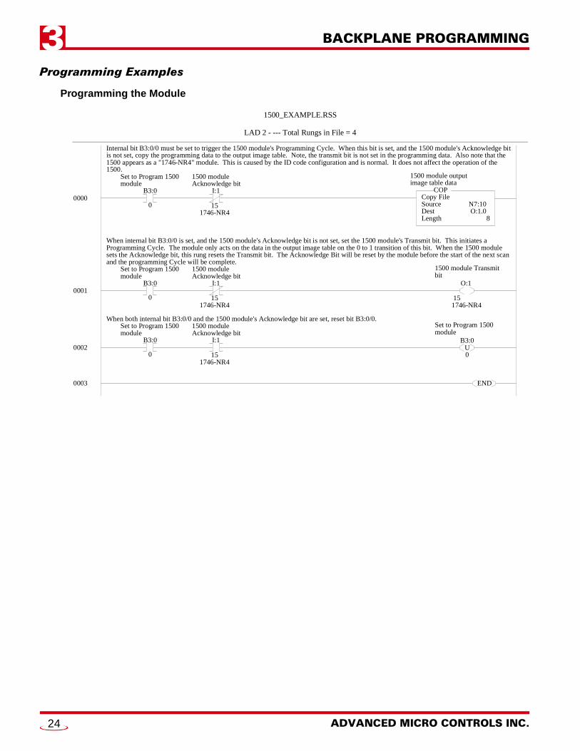
Programming ExamplesProgramming the Module
0000
1500_EXAMPLE.RSS
LAD 2 - --- Total Rungs in File = 4
1500 module outputimage table data
Copy FileSourceDestLength
COP
N7:100O:1.00
8
B3:0
0
Set to Program 1500module
I:1
151746-NR4
1500 moduleAcknowledge bit
Internal bit B3:0/0 must be set to trigger the 1500 module's Programming Cycle. When this bit is set, and the 1500 module's Acknowledge bitis not set, copy the programming data to the output image table. Note, the transmit bit is not set in the programming data. Also note that the1500 appears as a "1746-NR4" module. This is caused by the ID code configuration and is normal. It does not affect the operation of the1500.
0001
1500 module Transmitbit
B3:0
0
Set to Program 1500module
I:1
151746-NR4
1500 moduleAcknowledge bit
When internal bit B3:0/0 is set, and the 1500 module's Acknowledge bit is not set, set the 1500 module's Transmit bit. This initiates aProgramming Cycle. The module only acts on the data in the output image table on the 0 to 1 transition of this bit. When the 1500 modulesets the Acknowledge bit, this rung resets the Transmit bit. The Acknowledge Bit will be reset by the module before the start of the next scanand the programming Cycle will be complete.
O:1
151746-NR4
Set to Program 1500module
B3:0
0
Set to Program 1500module
I:1
151746-NR4
1500 moduleAcknowledge bit
When both internal bit B3:0/0 and the 1500 module's Acknowledge bit are set, reset bit B3:0/0.
0002B3:0
U0
0003 END
ADVANCED MICRO CONTROLS INC.24
BACKPLANE PROGRAMMING 3
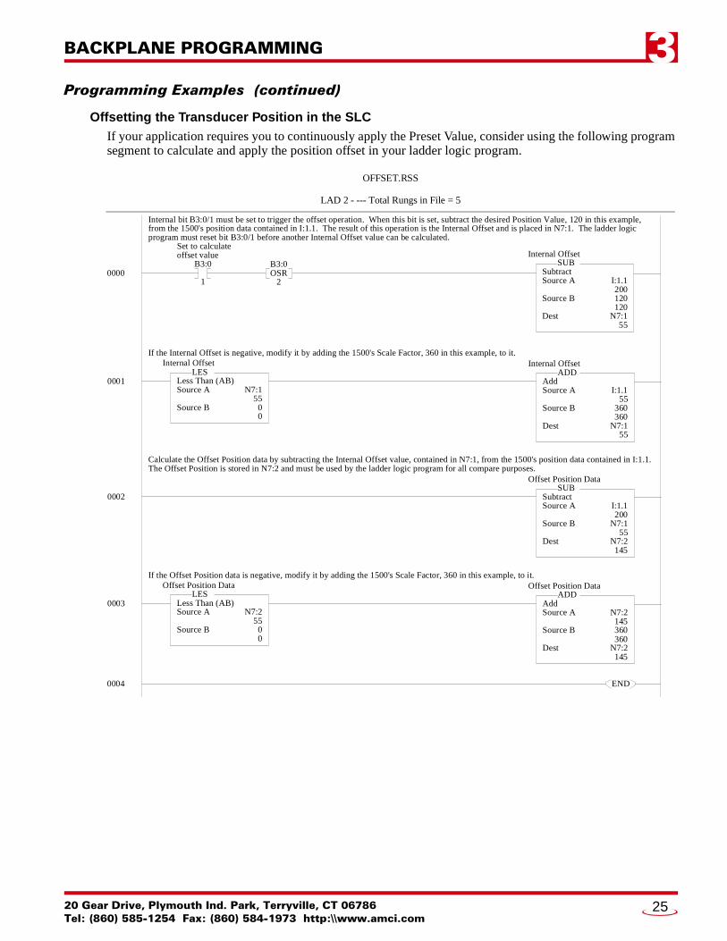
Programming Examples (continued)Offsetting the Transducer Position in the SLCIf your application requires you to continuously apply the Preset Value, consider using the following program segment to calculate and apply the position offset in your ladder logic program.
0000
OFFSET.RSS
LAD 2 - --- Total Rungs in File = 5
SubtractSource A
Source B
Dest
SUB
I:1.1200120120
N7:155
B3:0
1
Set to calculateoffset value
B3:0OSR
2
Internal bit B3:0/1 must be set to trigger the offset operation. When this bit is set, subtract the desired Position Value, 120 in this example, from the 1500's position data contained in I:1.1. The result of this operation is the Internal Offset and is placed in N7:1. The ladder logicprogram must reset bit B3:0/1 before another Internal Offset value can be calculated.
0004 END
Internal Offset
0001 AddSource A
Source B
Dest
ADD
I:1.155
360360
N7:155
If the Internal Offset is negative, modify it by adding the 1500's Scale Factor, 360 in this example, to it.Internal Offset
Less Than (AB)Source A
Source B
LES
N7:155
00
Internal Offset
0002 SubtractSource A
Source B
Dest
SUB
I:1.1200
N7:155
N7:2145
Calculate the Offset Position data by subtracting the Internal Offset value, contained in N7:1, from the 1500's position data contained in I:1.1.The Offset Position is stored in N7:2 and must be used by the ladder logic program for all compare purposes.
Offset Position Data
0003 AddSource A
Source B
Dest
ADD
N7:2145360360
N7:2145
If the Offset Position data is negative, modify it by adding the 1500's Scale Factor, 360 in this example, to it.Offset Position Data
Less Than (AB)Source A
Source B
LES
N7:255
00
Offset Position Data
20 Gear Drive, Plymouth Ind. Park, Terryville, CT 06786Tel: (860) 585-1254 Fax: (860) 584-1973 http:\\www.amci.com
25

L
ADV ANC ED MIC RO CONTROLS INC.ADV ANC ED MIC RO CONTROLS INC.ADV ANC ED MIC RO CONTROLS INC.ADV ANC ED MIC RO CONTROLS INC.20 GEAR DRIVE, TERRYVILLE, CT 06786 T: (860) 585-1254 F: (860) 584-1973
www.amci.com
EADERS IN ADVANCED CONTROL PRODUCTS