Embed Size (px)
Citation preview

Commercial/Industrial Control System
Installation, Operation and Maintenance Manual
Series 180

2
Table of Contents
Installation . . . . . . . . . . . . . . . . . . . . . . . . . . . . 3PlumbingInlet and Outlet PipingDrain Line PipingBrine Line Piping
Electrical . . . . . . . . . . . . . . . . . . . . . . . . . . . . . 4
Installing the Tank Adapter and Valve . . . . . . . 4
Conditioner Start-Up . . . . . . . . . . . . . . . . . . . . 5
Regeneration Cycle Time Instructions. . . . . . . 6Pin Time ChartSet Backwash Timing
Valve Positions. . . . . . . . . . . . . . . . . . . . . . . . . 7
Series 962 Electronic Control . . . . . . . . . . . . . 8
Programming the Series 962 Control . . . . . . . 9Factory Default ValuesProgram LevelsLevel I ProgrammingSetting Time of DayLevel II ProgrammingChanging a Program ValueLevel III ProgrammingLevel IV ProgrammingManual RegenerationEntering “d” Values (Regeneration Days)Viewing a Program ValueLock-out Feature
Flow Sensor Select Options . . . . . . . . . . . . . 11
Advance Cycle Function . . . . . . . . . . . . . . . . 11
Cancel Regeneration Function . . . . . . . . . . . 11
Capacity Based Regeneration Start Options . 12P15 = 0 or 2 Variable ReserveP15 = 1 or 3 Fixed ReserveP15 = 0 or 1 Delayed Regeneration OnlyP15=2 or 3 Immediate Regeneration OverrideImmediate Regeneration Only Option
Parallel Operation. . . . . . . . . . . . . . . . . . . . . . 16
Remote Regeneration . . . . . . . . . . . . . . . . . . 16
Flow Sensor Connections . . . . . . . . . . . . . . . 17
Final Check Out . . . . . . . . . . . . . . . . . . . . . . . 17
Injector and Backwash Control Sizing . . . . . . 17
Injector Flow Rate Chart . . . . . . . . . . . . . . . . 21
Pressure Drop Vs. Flow . . . . . . . . . . . . . . . . . 21
Flow Diagrams . . . . . . . . . . . . . . . . . . . . . . . . 22
Replacement Parts. . . . . . . . . . . . . . . . . . . . . 23
Parts List . . . . . . . . . . . . . . . . . . . . . . . . . . . . 24
Specifications. . . . . . . . . . . . . . . . . . . . . . . . . 25
3
Installation
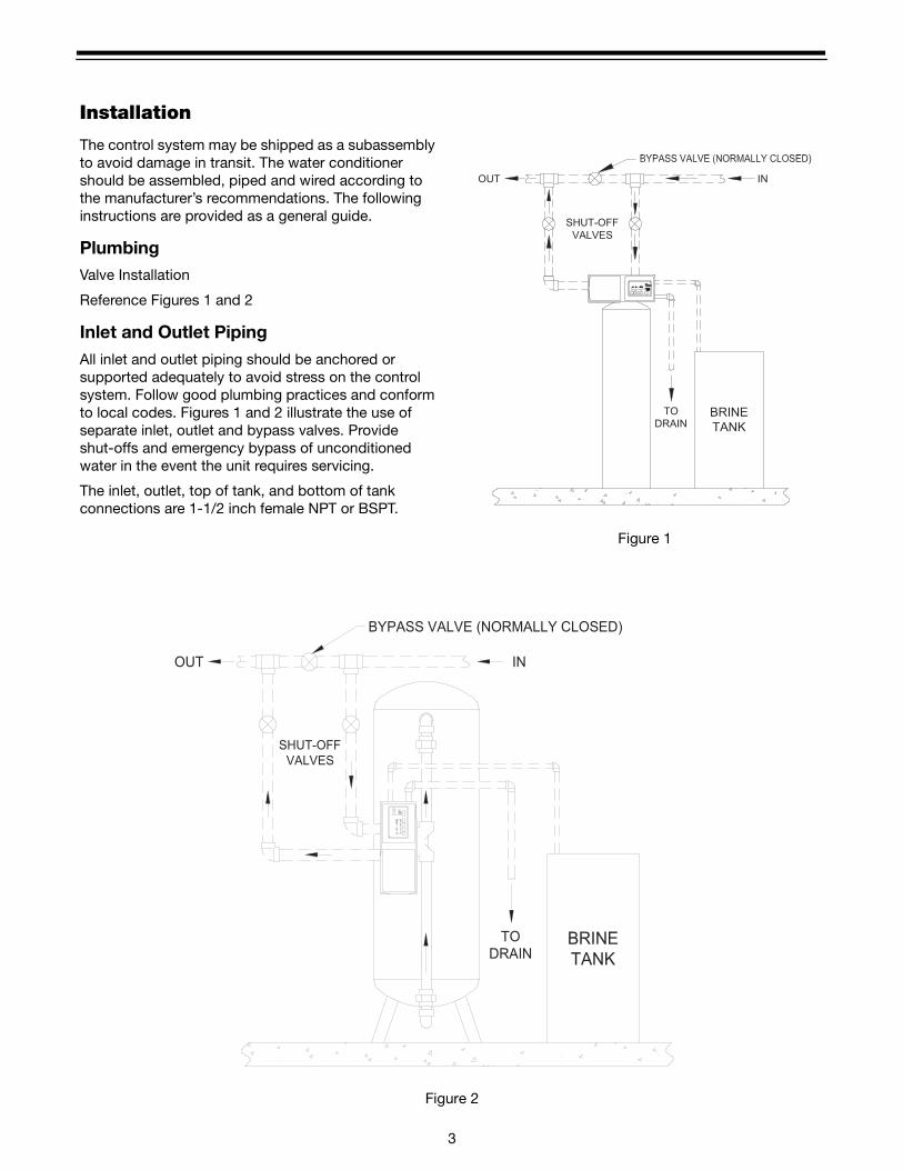
The control system may be shipped as a subassembly to avoid damage in transit. The water conditioner should be assembled, piped and wired according to the manufacturer’s recommendations. The following instructions are provided as a general guide.
PlumbingValve Installation
Reference Figures 1 and 2
Inlet and Outlet PipingAll inlet and outlet piping should be anchored or supported adequately to avoid stress on the control system. Follow good plumbing practices and conform to local codes. Figures 1 and 2 illustrate the use of separate inlet, outlet and bypass valves. Provide shut-offs and emergency bypass of unconditioned water in the event the unit requires servicing.
The inlet, outlet, top of tank, and bottom of tank connections are 1-1/2 inch female NPT or BSPT.
Figure 1
Figure 2
BRINE
TANK
SHUT-OFF
VALVES
INOUT
TO
DRAIN
BRINE
TANK
SHUT-OFF
VALVES
INOUT
TO
DRAIN
NOTE:
THE 180/962 CONTROL VALVE
WILL OPERATE IN A SIDE MOU
INSTALLATION. THIS
CONFIGURATION, HOWEVER,
NOT RECOMMENDED DUE TO
THE ORIENTATION OF THE
DISPLAY IN A VERTICAL
POSITION.
BYPASS VALVE (NORMALLY CLOSED)

4
Drain Line PipingReference Figures 1, 2 and 3.
The 3/4 inch NPT of BSPT drain fitting contains a flow control to accommodate backwash and fast rinse rates up to 25 gpm (94.6 lpm). Should higher flow rates be needed, an external flow control will be required.
To avoid regeneration problems, the following drain line precautions should be observed:
• Piping 3/4 inch or larger
• Overall length less than 30 feet (6.1 m)
• Not elevated higher than valve
• Not restricted
• No shut-off valves
• Minimum number of elbows and fittings
• Piping must be self-supporting without strain on valve drain fitting
• Open end termination to provide a siphon break
Figure 3
Brine Line PipingReference Figure 3.
The 1/2 inch NPT or BSPT brine connection is located between the inlet and outlet pipe connections of the control valve.
The brine tank should be located as close as possible to the conditioner tank. A float type brine valve must be used in the brine tank. Since the brine line is normally
pressurized, a manual shut-off valve should be installed to facilitate brine system servicing.
Brine line size should be no smaller than 1/2 inch. The brine line should be self-supporting. Use a minimum of fittings to assure unrestricted brine draw.
Electrical100VAC, 120VAC and 230VAC Units:
Remove the plastic cover, complete the wiring to terminals 2, 4 and 7 of the terminal block (Figure 22) for 440 Timers or to terminals 1, 2, 4 and 7 (Figure 23) for 450 Impulse Timers, and terminals 1, 4 and 8 (Figure 24) for 962 controllers. Reinstall the plastic cover.
Note: Conduit is recommended.
24VAC Units (Not valid for 962 Control):
The power supply transformer should have a minimum rating of 200 volt-amps to run the drive motor and timer motor. If additional electrical components, such as solenoid valves are connected to the terminal block, the volt-amp rating of the transformer must be increased to accommodate the load.
Remove the plastic cover, complete the wiring to terminals 2 and 4 of the terminal block (Figure 22) for 440 Timers or to terminals 1, 2 and 4 (Figure 23) for 450 Impulse Timers and reinstall the cover.
Installing the Tank Adapter and Valve-Top Mount1. Clean residual mineral from top of the tank and
threads.
2. Apply silicone grease to all O-rings (Figure 4), the bevel on top of the tank and to the top 1 inch of the riser pipe.
Figure 4
3. Install the tank adapter O-ring. Make sure the riser pipe is 1/8 to 1/4 inch below the top of the tank, Figure 5.
DRAIN
TO
SHUT-OFF
VALVES
OUT IN
BRINE
TANK
BYPASS VALVE (NORMALLY CLOSED)
MANUAL SHUT-OFF VALVE
(NORMALLY OPEN)
BRINE LINE
1/2 IN. PIPE MINIMUM
BRINE FLOAT
VALVE
O-RINGO-RING

5
4. Position the tank adapter in the opening of the tank with the riser pipe in the riser pipe seal. Thread the tank adapter into the tank and tighten until the tank adapter bottoms out on the tank.
5. Place the gasket on the tank adapter and position the valve.
6. Mount the valve using the five Allen head screws and tighten evenly.
Figure 5
Installing Valve - Side Mount1. Position the valve body on the side mount adapter
with the gasket in place, Figure 6.
2. Mount the valve using the five Allen screws provided and tighten evenly.
Figure 6
Conditioner Start Up1. Close inlet and outlet valves.
2. Close brine line valve if used.
3. Supply electrical power to unit(s). Fill brine tank(s) with water to a point 1 inch (2.5 cm) above grid using a hose or bucket. Do not add salt to brine tank at this time.
Caution: Keep hands away from drive linkage area when operating.
4. Push in red knob on timer, turn COUNTERCLOCKWISE until arrow points to START position. This will move the piston to the BACKWASH position.
5. Partially open inlet valve until a steady stream of water, free of air, flows from the drain. Open inlet valve fully.
Note: If top cover of conditioner tank can be removed to vent air, the tank may be filled more quickly
6. Open brine line valve. Allow the unit to BACKWASH until the timer moves the piston to the next position in approximately 12 minutes.
7. After the timer has moved the piston out of the BACKWASH position, it will move to the BRINE/SLOW RINSE position. Watch the level of water in the brine tank, it should move down at a steady rate. A drawdown of 2 to 3 inches is sufficient for checkout.
8. As in step 4, manually rotate the red knob COUNTERCLOCKWISE, slowly, until the piston moves into the FAST RINSE position.
9. Allow the valve to remain in the FAST RINSE position until the timer automatically moves the piston to the SERVICE position in approximately 11 minutes.
The unit is now ready to be put on line. Open the outlet valve, close the bypass valve and load the brine tanks.
Note: If installation consists of multiple tanks, use steps 1 through 9 for each conditioner.
Note: If using the 962 electronic demand controller, simply press and hold the REGEN button for 3 seconds to start a regeneration. To step through each regeneration cycle, press and hold the LEFT (←) arrow button for 3 seconds. This allows you to step through a quick regeneration.
Loading the Brine Tank (Grid System)1. The brine valve (located in the brine tank) will
automatically fill and maintain the water level in the brine tank. The water level must be 1 to 2 inches above the salt platform. If that level is not achieved, remove the brine valve (after shutting off the manual brine line valve) and adjust the float on the float rod.
2. Fill the brine tank with salt to a level even with the top of the brine well. Use a clean grade of softener salt, (pellet salt or equivalent). Rock salt is not recommended. Rock salt contains impurities that can cause malfunction of the brine valve.
1/8 TO 1/4 IN.
GASKET

6
Setting Series 440 TimersDetermine a regeneration schedule for the conditioner and adjust the automatic timer as follows (see Figures 7 and 8):
Figure 7
Figure 8
1. Pull all the skipper pins out (away from control).
2. Rotate skipper wheel until day arrow points to day of week or number 1.
3. Push in skipper pin(s) for day(s) regeneration is required.
4. Pull timer knob out (away from the timer face) and rotate until time arrow on timer knob points to correct time of day on face plate.
5. Timer will automatically initiate regeneration on preset days at 2:30 A.M. To alter time, simply reset timer knob to an earlier or later time which will change the time of regeneration by the same number of hours. (Time indicated at time arrow will no longer be correct).
Regeneration Cycle Time Instructions (440 and 450 Timers)
Pin Time Chart
*Each additional pin either pulled out or pushed in equals 3 minutes.
Set Backwash TimingPull pins as shown for desired backwash time. Reference Pin Time Chart.
Set Brine/Rinse TimingDepress pins as shown for desired brine/rinse time, minimum of two pins down. Reference Pin Time Chart.
Set Fast Rinse TimingPull pins as shown for desired fast rinse time. Reference Pin time Chart.
Figure 9 Timer, Rear View
MIDNIGHT
START RELEASE
COUNTERCLOCKWISE TO
DEPRESS RED KNOB TURN
REGENERATION
FOR MANUAL
THU
TU
E
DAY
WE
D
SA
TS
UN
MON
FRI
PM
SERVICESTART
3 A
M
PULL KNOB AND ROTATE
3 P
M
6 PM
TO SET TIME OF DAY
NO
ON
9 A
M
6 AM
REGENERATION
TO SET TIME OF DAY
PULL KNOB AND ROTATE
DEPRESS RED KNOB TURN
COUNTERCLOCKWISE TO
START RELEASE
3 A
MSERVICE
START
PM
MIDNIGHT
DAY
9 A
M
6 AM
3 P
M
NO
ON
6 PM
FOR MANUAL
6
21
45
3
Backwash or Fast Rinse
Brine/Rinse
No. of Pins OUT
TimeNo. of Pins
INTime
1 8 min. 2 1.5 min.2 11 min. 3 4.5 min.3 14 min. 4 7.5 min.4 17 min. 5 10.5 min.5 20 min. 6 13.5 min.6 23 min. 7 16.5 min.7 26 min. 8 19.5 min.8 29 min. 9 22.5 min.9 32 min. 10 25.5 min.
10 35 min. 11 28.5 min.11 38 min. 12 31.5 min.12 41 min. 13 34.5 min.13 44 min. 14 37.5 min.14 47 min. 15 40.5 min.15 50 min. 16 43.5 min.* *

7
Typical Water Conditioning Cycle
Backwash 14 min. 3 pins outwardBrine/Rinse 40.5 min. 15 pins outwardFast Rinse 11 min. 2 pins outward
Remaining pins in
Variation Water Conditioning Cycle
Backwash 14 min. 3 pins outwardBrine/Rinse 85.5 min. 30 pins outwardFast Rinse 11 min. 2 pins outward
Typical Filter Application Cycle
Backwash 20 min. 5 pins outwardPause 1.5 min. 2 pins inwardFast Rinse 11 min. 2 pins outward
Valve Positions
Figure 10 - Backwash Position
Figure 11 - Brine and Slow Rinse Position
Figure 12 - Fast Rinse Position
Figure 13 - Service Position

8
Series 962 Electronic ControlThe Series 962 Electronic Control provides sophisticated, demand-based water conditioning by combining a microprocessor with a flow meter to electronically monitor the amount of water used. This fully programmable series of controls provide the ability to fine-tune the operation to meet the application requirements.
Special Features of the Series 962 Control
Memory RetentionDuring a power outage, critical operating information is stored in nonvolatile memory. This information includes the time of day, water usage, all programming data and the number of days since the last regeneration. When power is restored, the information is returned to the microprocessor and operation resumes as if an outage never occurred. The time of day will be late by the length of the power outage. The time of day should be reset after an extended power outage. No other reprogramming is necessary. The addition of an optional rechargeable backup battery will allow the control to keep track of time and water usage for up to 8 hours during a power outage. The control will not initiate a regeneration while on battery backup.
Figure 14
Double RegenerationFor single tank applications, the control automatically calls for a second regeneration the following day if the current operation cycle exceeds the programmed capacity by 150% or more.
Capacity Setting LockoutThe control can be programmed to lock the capacity so it cannot be altered after installation.
Selectable Reserve OptionsTo meet the application requirements, the control allows selection of one of two reserve types:
Fixed Reserve - The reserve is fixed at a programmable percentage (30% factory preset) of the total capacity.
Variable Reserve - The controller monitors the daily water usage and at the programmed time of regeneration, calculates the average water used for each day of the week. The reserve capacity is set to 120% of the average water usage for the next day.
U.S. or Metric Units of MeasureTo meet your display and programming requirements, the 962 control uses grains per gallon of hardness and kilograins of capacity for U.S. units; or parts per million of hardness and kilograms of capacity as gallons or cubic meters.
Calendar OverrideIf the volume of water used has not caused a regeneration, the 962 control can be set to regenerate every one to thirty days.
Manual RegenerationA separate REGEN button is provided for manual regenerations. A double manual regeneration feature is included that allows back-to-back regenerations.
Operating HistoriesImportant operating data is stored in memory and is retrievable upon demand.
The historical data includes peak flow data as well as average daily water usage for each day of the week.
Remote RegenerationA set of input terminals with a programmable delay are provided as a standard feature of the 962 control that allows regeneration to be initiated from a remote location. This feature can be used to facilitate remote manual regeneration requirements or assist in further automating the control system such as the use of a differential pressure switch.
Selectable Automatic RegenerationsThere are four automatic regeneration methods; “delayed with immediate override”, “delayed only”, “day of week”, and “calendar override”. Immediate regeneration is used to start an automatic regeneration immediately when the capacity remaining in a tank is reduced to zero. Delayed regeneration is used to start an automatic regeneration at a predetermined time of
on battery backup.

9
day when the capacity remaining is below a defined reserve. The reserve capacity may be fixed or variable. The variable reserve is determined by past usage history. Regeneration can be accomplished based on the day of the week at a specific time of day or after programmable number of days since the last regeneration.
Optional Battery BackupAn optional battery backup can be provided so that the Time of Day and water usage will be maintained for up to 8 hours during a power outage. All 180/962 control valves are provided as “Battery Backup Capable”. Batteries can be purchased separately. The control has a trickle charge circuit that will recharge the battery in the event it is depleted by a power outage. If the optional battery backup is provided with the Series 962, make sure that it is properly connected.
Note: A standard 9V alkaline battery may be used as a substitute, but will not be rechargeable.
Figure 15
Flow Rate DisplayIn the normal operating mode the series 962 control will alternate between Capacity Remaining (gallons or m3) and Flow Rate (gallons per minute or m3/hr). In the event of power loss, (including battery power) the display will alternate between Time of Day and Capacity Remaining once power has been restored. The control will remain in this display mode until the Time of Day is reset or until any button is pressed.
Programming the Series 962 ControlThis section contains common aspects of programming the 962 control and retrieving historical operating data. A label provided with the control should be filled out with programming parameters on system start-up.
Factory Default ValuesThe control is shipped from the factory pre-programmed with the correct operation type. Capacity and Hardness values are set to 0 and must be changed to appropriate values before the control will operate. “Err 4” will be displayed until a valid number is entered for each of these items. Program variable P12 is set to U.S. units of measure or metric units at the factory to match geographical shipping locations.
Program LevelsThe Series 962 controls have been designed to facilitate different levels of programming requirements. Level I includes program variables that are frequently referenced by users, operators, installers and service personnel. They are accessible without the requirement of codes. Level II includes variables that are most typically used at the time of installation and initial setup. These are accessible with only access codes. Level III locations are used primarily for accessing operation history information. Level IV locations are used to set the regeneration days of the week. Level III and IV parameters also require access codes. Programming levels are further defined in Tables I, II, and III.
Levels Access Code
I None Required
IIPress and hold the (↑ ) and (↓) arrow
buttons for 3 seconds
IIIPress and hold the (←) and (↑ ) arrow
buttons for 3 seconds
IVPress and hold the (←) and (↓) arrow buttons for 3 seconds

10
Level I ProgrammingLevel I Program values are identified by the legend on the faceplate of the control. A green LED that is illuminated when a Level I "P” value is displayed. Following are the Level I “P” values:
• Time of Day P1• Time of Regeneration P2• Hardness P3• Capacity P5
P4 is used to program the salt amount. The 962/180 does not require a salt amount.
Setting Time of DayPress the SET button. The display will show the time of day with the minutes digit blinking. Press the UP (↑ ) arrow button to increase the number or the DOWN (↓) arrow button to decrease the number. To skip the number without changing, press the LEFT (←) arrow button. The first digit will stop flashing and the next digit will start flashing. When the far left digit is reached, pressing the LEFT (←) arrow button returns the flashing to the far right digit. Continue changing numbers until the desired Time of Day is obtained. Press the SET button to enter the value. The PM indicator will toggle when the “tens digit” of the hours is increased. The far left digit is used to indicate the day of week. Number 1 being Sunday and number 7 being Saturday.
The time of Regeneration, Hardness, and Capacity are set in a similar manner.
The control will automatically enter Level II programming if P19 or P20 have not been set.
Level II ProgrammingPress and hold the (↑ ) and (↓) arrow buttons for 3 seconds to enter the Level II programming mode. The display will show the letter “P” in the far left display digit. The parameter “P-number” is displayed in the far right display digit. See Table 1 for Level I and II programming values.
Changing a Program ValueOnce the P value you want to change is displayed, press the (←) arrow button to display the current entry for that value. To change or modify the value, press the SET button. The digit on the right hand side of the display will begin to flash. Use the (↑ ) or (↓) arrow buttons to select the desired entry. Once the desired entry is obtained, press the (←) button to move to the next digit and change as needed. Once you have completed the appropriate changes, press the SET button. When you press the SET button the new entry is stored and the control automatically scrolls to the next P value. If a beep sounds, the new entry was not
accepted. Table 1 lists the range available for a specific program value.
Level III ProgrammingPress and hold the (←) and (↑ ) arrow buttons for 3 seconds to enter the Level III programming mode. The display will show the letter “L” in the far left display digit. The parameter “L-number” is displayed in the far right display digit. The SET button is inactive except for L4. If SET is pressed when L4 is displayed, Peak Flow is reset to zero. If SET is pressed when any other location is displayed the control will beep.
Level IV ProgrammingPress and hold the (←) and (↓) arrow buttons for 3 seconds to enter the Level IV programming mode. Level IV programming is used to enter the day of week regeneration settings.
Manual RegenerationTo initiate a manual regeneration, simply press and hold the REGEN button for 3 seconds. If an immediate second regeneration is desired, wait for at least one minute after the first regeneration begins and then press and hold the REGEN button for 3 seconds. A second regeneration will be performed immediately following the first. The display will freeze and only show the regeneration Time Remaining as an indication that the second regeneration will be initiated. When the first regeneration is complete, the second regeneration will begin and the display will alternate between Flow Rate and Regeneration Time Remaining.
Entering “d” Values (Regeneration Days)“d” values are used to start a regeneration on a certain day of the week. There are seven “d” values numbered from 1 to 7, with 1 representing Sunday and 7 representing Saturday. Set a 1 in “d7” to initiate an automatic regeneration every Saturday at the Time of Regeneration (P2). The automatic regenerations will occur at the time set in P2 regardless of the capacity remaining in the system. A value of “0” indicates no regeneration on that day. The default value is “0” for all “d” values.
Viewing a Program ValueProgrammed values may be viewed at any time. Program values may not be changed during a regeneration.
Level I - To locate and display a P value in Level I press the (↑ ) or (↓) arrow button until the desired value is displayed. Level I parameters are indicated by the legend on the face plate of the control.

11
Level II - To locate and display a P value in Level II, simultaneously press the (↑ ) and (↓) arrow buttons for 3 seconds to gain access. Press the (↑ ) or (↓) arrow buttons until the desired location is displayed. Press (←) to display the value in the P location.
Level III - To locate and display an L value in Level III, simultaneously press the (←) and (↑ ) arrow buttons for 3 seconds to gain access an then press the (↑ ) or (↓) arrow buttons until the desired location is displayed. Press (←) to display the value in the L location.
Level IV - To locate and display a “d” value in Level IV, simultaneously press the (←) and (↓) arrow buttons for 3 seconds to gain access and then press the (↑ ) or (↓) arrow buttons until the desired location is displayed. Press (←) to display the value in the location.
Lock-Out FeatureThe lock-out feature may also be used to prevent regenerations when a signal is present at the lock-out terminals. Two or more 962 controls can be connected together (see Figure 16) to prevent one from regenerating while another is in regeneration. This signal can also come from external equipment that can provide a dry contact closure. (CONNECTION MUST BE A DRY CONTACT).
Flow Sensor Select OptionsP19 is used to select the flow sensor type. Numbers 1 and 2 are for the Autotrol 1 inch and 2 inch turbine type flow sensors. The number in P20 will be ignored when P19 is programmed with a 1 or 2.
Other flow sensors can be used by entering a “3” in P19 and entering the correct “K-factor” in P20. The K-factor is defined as pulses per gallon for U.S. units or pulses per liter for metric units. The K-factor can be obtained from the flow sensor manufacturer.
If a “4” is entered in P19 then the definition of the number in P20 becomes gallons or liters per pulse depending on the units of measure selected.
Advance Cycle FunctionWhile in a regeneration cycle, you can advance the 180 valve to the next cycle by pressing and holding the left arrow key (←) for 3 seconds. The 180 valve and controller will then advance to the next regeneration cycle.
Cancel Regeneration FunctionTo cancel (abort) a regeneration, press and hold the left arrow (←) and SET keys for 3 seconds. The control will display an ERROR 3 and return the 180 valve to the service (Home) position. Once in the service position, ERROR 3 will be cleared.
Capacity Based Regeneration Start OptionsThe following is an explanation of the regeneration start options for single tank 962 controls.
At the time of regeneration (time set in P2) the control will check to see if a regeneration should start. This check depends on the value programmed in P15.
P15 = 0 or 2 Variable ReserveThe control calculates an average water usage for each day of the week when it is using variable reserve. A regeneration will start if the capacity remaining is less than 1.2 times the average water usage for the next day.
P15 = 1 or 3 Fixed ReserveThe reserve capacity is calculated using the fixed reserve capacity programmed in P16. The value in P16 is the percentage of the calculated system capacity used for the reserve.
Example: If the programmed capacity is 10,000 grains and the hardness is 10 grains/gallon the calculated system capacity is 1000 gallons. The reserve capacity is 300 gallons if the fixed reserve is set to 30%. A regeneration will start if the capacity remaining at the time of regeneration is less than 300 gallons.
The parameter P15 is also used to select immediate regenerations or delayed regenerations only.
P15 = 0 or 1 Delayed Regeneration OnlyAutomatic regenerations will occur at the time of regeneration only. The control will delay the start of regeneration until the time of regeneration even if the capacity remaining is reduced to zero gallons.
P15 = 2 or 3 Immediate Regeneration OverrideIn addition to delayed regenerations automatic regenerations will occur at any time during the day if the capacity remaining reaches zero.
Immediate Regeneration Only OptionAutomatic regenerations performed at the time of regeneration (P2) can be eliminated by setting the control for fixed reserve with immediate regeneration override (P15 = 3) and setting the reserve capacity percentage (P16) to 0%. This will create a reserve capacity of zero gallons. These are the preferred settings for a twin alternating softener system.

12
Table 1 - Level I and II Parameters
Parameter Range of Values
Minimum Increments
Default Units of Measure
NotesName Description
P1Day of week and
time of day
(1-7) 1:00-12:59
AM or PM(1-7) 0:00 -
23:59
(1 day)1 minute
None hour:minute
Range depends on value selected for P13
For day of week, SUN=1, MON=2, TUE=3, WED=4,
THU=5, FRI=6, SAT=7
P2Time of day to
start regeneration
1:00-12:59 AM or PM0:00-23:59
1 minute 2:00 AM Hour:minuteRange depends on value
selected for P13. Use only if P15 = 1
P3Hardness of
water3-250
30-2500110
00
grains/gallonppm
Unit of measure depends on value selected for P12
P4 Not Used
P5 Capacity of unit1-5100
.1-510.01.1
0kilograins*kilograms*
Unit of measure depends on value selected for P12
P6 Not UsedP7 Not UsedP8 Not UsedP9 Backwash time 1-30 1 14 minutes
P10 Rinse/Draw time 1-125 1 40 minutesP11 Rinse time 1-19 1 4 minutes
P12 Units of measure 0-1 1 00 = US
1 = Metric
P13 Clock mode 0-1 1 00 = 12 hour clock1 = 24 hour clock
P14Calendar override
0-30 1 0 days 0 = no calendar override
P15 Reserve Type 0-3 1 0
0 = Variable reserve1 = fixed reserve
2 = variable reserve with immediate regeneration3 = fixed reserve with
immediate regen
P16Initial average usage or fixed
reserve0-70 1 30
% of capacity
Description depends on value entered for P15
P17 Operation type 3-9 1 45 = 4 cycle 180 valve (Butterfly
configuration)
P18Capacity change
lock-out0-1 1 0
0 = none1 = capacity change
locked-out
P19Flow sensor
select1-4 1 3
1 = 1.0” Autotrol turbine2 = 2.0” Autotrol turbine
3 = User defined K-factor (PPG)
4 = User defined pulse equivalent (GPP)
P20 K-factor or pulse
equivalent0.01-255.00 .01 0.01
Number used for meter K-factor or pulse equivalent
P21Remote
regeneration switch delay
1-254 1 60 secondsTime remote switch must be active to start a regeneration
P22 Do not use P 22. Factory use only.
*See Table 1A for conversions.

13
Table 1A Conversion
To Convert Capacity in
Into Capacity in Multiply by
kilograms (kg) kilograins (kgr) 15.43kilograins (kgr) kilograms (kg) 0.0648
moles of CaCO3 kilograms (kg) 0.10equivalents of CaCO3 kilograms (kg) 0.05
Table 2 Level III History Data
Location Range DescriptionL 1 1-7 Day of week (Sun=1, Sat=7)L 2 0-255 Days since last regenerationL 3 1:00-12:59/0:00-23:59 Time that peak flow occurred
L4 0-200/0-50.0Peak flow gallons per minute/cubic meters (M3) per hour since location reset
L 5 0-655360/0-6553.6 Water used today in gallons/M≥ since time of regenerationL 6 0-655360/0-6553.6 Water used since last regeneration in gallons/M3
L 7 0-655360/0-6553.6 Average water usage for Sunday in gallons/M3
L 8 0-655360/0-6553.6 Average water usage for Monday in gallons/M3
L 9 0-655360/0-6553.6 Average water usage for Tuesday in gallons/M3
L 10 0-655360/0-6553.6 Average water usage for Wednesday in gallons/M3
L 11 0-655360/0-6553.6 Average water usage for Thursday in gallons/M3
L 12 0-655360/0-6553.6 Average water usage for Friday in gallons/M3
L 13 0-655360/0-6553.6 Average water usage for Saturday in gallons/M3
L 14 0-999990/0-99999.9 Total water used since NOVRAM test in gallons/M3 (LSD)L 15 0-167/0-16 Total water used since NOVRAM test in gallons/M3 x 106 (MSD)
Table 3 Level IV Parameters
#Description of
ParameterRange of
ValuesMinimum Increment
Default Notes
d1 Sunday 0-1 1 0 0 = no day of week regen this dayd2 Monday 0-1 1 0 0 = no day of week regen this dayd3 Tuesday 0-1 1 0 0 = no day of week regen this dayd4 Wednesday 0-1 1 0 0 = no day of week regen this dayd5 Thursday 0-1 1 0 0 = no day of week regen this dayd6 Friday 0-1 1 0 0 = no day of week regen this dayd7 Saturday 0-1 1 0 0 = no day of week regen this day

14
Installation Programmed Values Chart
Table 4 Error Code Identification
Error Code Description1 Data stored in NOVRAM has been corrupted and is incorrect2 Home switch (SW 2) closed when it should be open3 Home switch (SW 2) open when it should be closed4 One or more parameters are below the minimum value in Table I
5System capacity less than 10 gallons or 0.1 m3 (Capacity is set too low or Hardness is
set too high)
Installation Date:
“P”Value
Description Install Values“d”
ValueDescription Install Values
P1Day of week/Time of day
d1 Regenerate on Sunday
P2 Time of regeneration d2 Regenerate on Monday
P3 Hardness of water d3 Regenerate on Tuesday
P4 Not used d4 Regenerate on Wednesday
P5 Capacity of unit d5 Regenerate on Thursday
P6 Not used d6 Regenerate on Friday
P7 Not used d7 Regenerate on Saturday
P8 Not used
P9 Backwash time
P10 Rinse/Draw time
P11 Purge time
P12 Units of measure
P13 Clock Mode
P14 Calendar override
P15 Reserve type
P16Initial average value of fixed reserve capacity
P17 Operation type
P18Capacity change lock out
P19 Turbine select
P20K-factor or pulse equivalent
P21Remote regeneration switch delay

15
Parallel OperationThe 962 control can be used for twin and triple tank applications, operating in a parallel mode. Parallel systems can be implemented with up to three individual controls by using the lock-out feature. Each control will provide a lock-out signal when it is in regeneration. This lock-out signal will prevent other controls from starting a regeneration when the controls are connected as in Figure 16.
Figure 16
Remote RegenerationA set of terminals with a programmable delay (P21) are provided as a standard feature of the 962 control, Figure 17. This feature allows for a regeneration to be initiated from a remote location. This feature can also be used to accommodate a differential pressure switch input or any dry contact closure from external equipment. Programmable value “P21” is used to monitor this input for the amount of time that is programmed (in seconds).
P21 is the length of time (in seconds) that the remote input signal will be ignored before starting a regeneration. (CONNECTION MUST BE A DRY CONTACT).
Figure 17

16
Flow Sensor ConnectionsThe 962 control may be connected to a number of different flow sensing devices. Figure 18 shows the connections for the Autotrol turbine type flow sensor. Figure 19 shows the connections for the Signet flow sensor. Most of the flow sensors that are used will be wired similarly, though the wire colors may vary.
Note: The 962 may also be used with two-wire “Contacting Head” meters (Pulse Equivalent, P19 set to a 4) by connecting the meter leads to terminals 12 and 13 respectively.
Figure 18 Autotrol Turbine Meter
Figure 19 Signet Flow Sensor
Final Check Out1. Test for soft water from a convenient soft water tap.
2. Manual bypass valve must be closed, reference Figures 1 and 2.
3. Manual inlet and outlet valves open, reference Figures 1 and 2.
4. Brine line shut-off valve open, reference Figure 3.
5. Drain line clear and unobstructed.
6. Electrical power to timer (not controlled by switch).
7. Time of day, frequency of regeneration, backwash time and brine/rinse time set properly.
8. Proper liquid level in brine tank.
9. Salt in brine tank.
Manual Initiation of Regeneration (TIMER)Push in red knob and turn COUNTERCLOCKWISE to START position. Release. Unit will go through a complete regeneration as programmed.
Manual Initiation of Regeneration (962 Control)Press and hold the REGEN key on the keypad for 3 seconds. Unit will go through a complete regeneration as programmed.
Note: You can advance through each regeneration cycle quickly by pressing the (←) left arrow key for 3 seconds. This will advance the controller and valve to the next regeneration cycle.
Injector and Backwash Control SizingSuggested Injector SizeA size injector (yellow) . . . . . . . . . . . . . . . . . . . . . . . . . . . . . . . . . . . . . . . . . . 12 in (30.5 cm) thru 14 in (35.6 cm) tankB size injector (orange) . . . . . . . . . . . . . . . . . . . . . . . . . . . . . . . . . . . . . . . . . 16 in (40.6 cm) thru 18 in (45.7 cm) tankC size injector (gold) . . . . . . . . . . . . . . . . . . . . . . . . . . . . . . . . . . . . . . . . . . . 20 in (50.8 cm) thru 24 in (61.0 cm) tank
Suggested Backwash Control Size4.0 gpm NPT or BSPT . . . . . . . . . . . . . . . . . . . . . . . . . . . . . . . . . . . . . . . . . 12 in (30.5 cm) thru 13 in (33.09 cm) tank5.0 gpm NPT or BSPT . . . . . . . . . . . . . . . . . . . . . . . . . . . . . . . . . . . . . . . . . . . . . . . . . . . . . . . . . . 14 in (35.6 cm) tank6.0 gpm NPT or BSPT . . . . . . . . . . . . . . . . . . . . . . . . . . . . . . . . . . . . . . . . . . 16 in (40.6 cm) thru 18 in (45.7 cm) tank10.0 gpm NPT or BSPT . . . . . . . . . . . . . . . . . . . . . . . . . . . . . . . . . . . . . . . . . . . . . . . . . . . . . . . . . 20 in (50.8 cm) tank15.0 gpm NPT or BSPT . . . . . . . . . . . . . . . . . . . . . . . . . . . . . . . . . . . . . . . . . . . . . . . . . . . . .For filter applications onlyOpen NPT or BSPT . . . . . . . . . . . . . . . . . . . . . . . . . . . . . . . For filter applications only, external flow control required
GREEN
WHITE
BLACK
RED
TB2 - (LOW VOLTAGE)
11
12
13
14
Turbine
Probe
+12VDC
SIGNAL
SHIELD (BARE)
(BLACK)
(RED)
(WHITE)GROUND
GREEN
WHITE
BLACK
RED
TB2 - (LOW VOLTAGE)
11
12
13
14
Flow
Sensor
+12VDC
SIGNAL
SHIELD (BARE)
(RED)
(BLACK)

17
Figure 20 Normal Installation
Figure 21 Installation with Service Valves, With or Without Hardwater Bypass
BRINE
TANK
SHUT-OFF
VALVESIN
OUT
BYPASS VALVE
(NORMALLY CLOSED)
OPTIONAL BYPASS
LOCK OUT
(NORMALLY OPEN)
(SOLENOID OPERATED)
SOFTENER TANK
DRAIN PORT
BRINE DRAWLINE
TO
DRAIN
BRINE
TANK
OPTIONAL BYPASS
LOCK OUT
(NORMALLY OPEN)
(SOLENOID OPERATED)
BYPASS VALVE
(NORMALLY CLOSED)
OUT
IN
SHUT OFF VALVE
SHUT OFF
VALVE
OUTLET SERVICE
VALVE - N.O.
INLET SERVICE
VALVE - N.O.
DRAIN PORT
SOFTENER TANK
LINEBRINE DRAW
TO
DRAIN

18
Figure 22 Wiring Diagram - 440 Six-Day or Seven-Day Timer

19
Figure 23 Wiring Diagram - 450 Impulse Timer

20
Figure 24

21
Injector Flow Rate Chart
Pressure Drop vs Flow
PSI (Kg/cm)
A Injector B Injector C InjectorDraw Rinse Draw Rinse Draw Rinse
gpm (Lpm) gpm (Lpm) gpm (Lpm) gpm (Lpm) gpm (Lpm) gpm (Lpm)
20 (1.4) 0.7 (2.6) .8 (3.0) 8 (3.0) 1.2 (4.5) .8 (3.0) 2.2 (8.3)
30 (2.1) 1.1 (4.1) 1.0 (3.8) 1.2 (4.5) 1.6 (6.0) 1.2 (4.5) 2.8 (10.6)
60 (4.2) 1.3 (4.9) 1.2 (4.5) 1.3 (4.9) 1.7 (6.4) 1.5 (5.7) 3.3 (12.5)
80 (5.6) 1.4 (5.3) 1.4 (5.3) 1.5 (5.7) 2.0 (7.6) 1.7 (6.4) 3.8 (14.4)
100 (7.0) 1.4 (5.3) 1.5 (5.7) 1.5 (5.7) 2.2 (8.3) 1.8 (6.8) 4.1 (15.5)
PSI(Kg/cm)
Service (Cv 12.9) Fast Rinse (Cv 6.1) Backwash (Cv 9.6)gpm (Lpm) gpm (Lpm) gpm (Lpm)
5 (0.35) 29 (110) 13 (49) 20 (76)
10 (0.70) 40 (151) 19 (72) 30 (114)
15 (1.00) 50 (189) 23 (86) 37 (140)
20 (1.40) 58 (220) 26 (98) 44 (167)
25 (1.70) 64 (242) 30 (114) 48 (182)
30 (2.10) 70 (265) 32 (121) 53 (201)
22
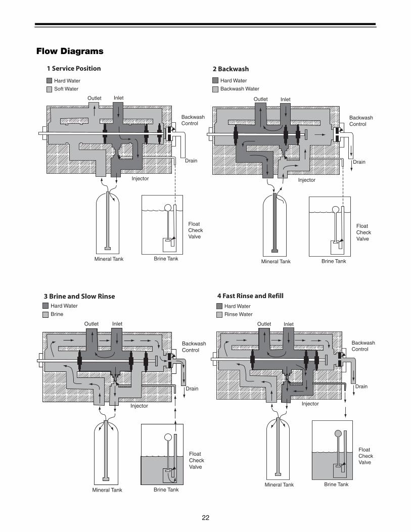
Flow Diagrams
InletOutlet
BackwashControl
Drain
Brine TankMineral Tank
Injector
FloatCheckValve
Hard Water
Soft Water
1 Service Position
InletOutlet
BackwashControl
Drain
Brine TankMineral Tank
Injector
FloatCheckValve
Hard Water
Backwash Water
2 Backwash
InletOutlet
BackwashControl
Drain
Brine TankMineral Tank
Injector
FloatCheckValve
Hard Water
Brine
3 Brine and Slow Rinse
InletOutlet
BackwashControl
Drain
Brine TankMineral Tank
Injector
FloatCheckValve
Hard Water
Rinse Water
4 Fast Rinse and Refill

23
Replacement Parts - Valve
962 Electronic Controller Parts
24
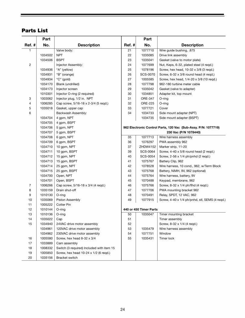
Parts List
Ref. #
Part
No. Description Ref. #
Part
No. Description1 Valve body: 21 1077710 Wire guide bushing, .875
1034502 NPT 22 1035085 Drive link assembly
1034506 BSPT 23 1035041 Gasket (valve to motor plate)
2 Injector Assembly: 24 1077699 Nut, Keps, 6-32, plated steel (4 reqd.)
1034936 “A” (yellow) 25 1078196 Screw, hex head, 10-32 x 3/8 (3 reqd.)
1034931 “B” (orange) 26 SCS-0070 Screw, 6-32 x 3/8 round head (4 reqd.)
1034934 “C” (gold) 27 1005585 Screw, hex head, 1/4-20 x 3/8 (10 reqd.)
1034170 Blank (undrilled) 28 1077798 962-180 turbine meter cable
1034173 Injector screen 29 1035042 Gasket (valve to adapter)
1010301 Injector O-ring (2 required) 30 1034851 Adapter kit, top mount
3 1003062 Injector plug, 1/2 in. NPT 31 ORE-347 O-ring
4 1006285 Cap screw, 5/16-18 x 2-3/4 (5 reqd.) 32 ORE-225 O-ring
5 1035018 Gasket, upper cap 33 1077721 Cover
6 Backwash Assembly: 34 1034733 Side mount adapter (NPT)
1034704 4 gpm, NPT 1034735 Side mount adapter (BSPT)
1034705 4 gpm, BSPT
1034706 5 gpm, NPT 962 Electronic Control Parts, 120 Vac (Sub-Assy. P/N: 1077719)
1034707 5 gpm, BSPT 230 Vac (P/N 1078440)
1034708 6 gpm, NPT 35 1077713 Wire harness assembly
1034709 6 gpm, BSPT 36 1076297 PWA assembly 962
1034710 10 gpm, NPT 37 ZHDW4152 Marker strip, 11-20
1034711 10 gpm, BSPT 39 SCS-0064 Screw, 4-40 x 5/8 round head (2 reqd.)
1034712 15 gpm, NPT 40 SCS-0054 Screw, 2-56 x 1/4 ph/pnhd (2 reqd.)
1034713 15 gpm, BSPT 41 1075767 Battery Clip, 962
1034714 25 gpm, NPT 42 1078528 Wire harness, 10 cond., 962, w/Term Block
1034715 25 gpm, BSPT 43 1075768 Battery, NiMH, 9V, 962 (optional)
1034700 Open, NPT 44 1075764 Wire harness, battery, 9V
1034701 Open, BSPT 45 1070488 Keypad, membrane, 962
7 1006266 Cap screw, 5/16-18 x 3/4 (4 reqd.) 46 1075766 Screw, 8-32 x 1/4 ph/flhd (4 reqd.)
8 1035159 Drain shut-off 47 1077706 PWA mounting bracket 962
9 1010130 O-ring 48 1070491 Relay, SPDT, 12 VAC, 962
10 1035069 Piston Assembly 49 1077915 Screw, 4-40 x 1/4 ph/pnhd, stl, SEMS (4 reqd.)
11 1005222 Cotter Pin
12 1010144 O-ring 440 or 450 Timer Parts
13 1010136 O-ring 50 1035047 Timer mounting bracket
14 1035022 Cap 51 Timer assembly
15 1034940 24VAC drive motor assembly 52 Screw, 8-32 x 1/4 (4 reqd.)
1034961 120VAC drive motor assembly 53 1035479 Wire harness assembly
1034962 230VAC drive motor assembly 54 1077751 Window
16 1005580 Screw, hex head 8-32 x 3/4 55 1035431 Timer lock
17 1033889 Cam assembly
18 1008332 Switch (3 required) Included with item 15
19 1005850 Screw, hex head 10-24 x 1/2 (6 reqd.)
20 1035156 Bracket switch

25
Specifications
Hydrostatic test pressure . . . . . . . . . . . . . . . . . . . . . . . . . . . . . . . . . . . . . . . . . . . . . . . . . . . . . . . . . 250 psi (17.2 bar)Working pressure. . . . . . . . . . . . . . . . . . . . . . . . . . . . . . . . . . . . . . . . . . . . . . . . . . . . . . . . . 20-100 psi (1.28-6.89 bar)Standard electrical rating . . . . . . . . . . . . . . . . . . . . . . . . . . . . . . . . . . . . . . . . . . . . . . . . . . . . . . . . . . . . . . 120V/60HzOptional electrical ratings (timers) . . . . . . . . .24V/50 Hz, 24V/60Hz, 120V/50Hz, 100V/60Hz, 100V/50Hz, 230V/50HzOptional electrical ratings (962 controller) . . . . . . . . . . . . . . . . . . . . . . . . . . . . . . . . . . . . . . . . . . . . . . . . 230V 50/60HzElectrical Cord (when furnished, with standard rating) . . . . . . . . . . . . . . . . . . . . . . . . . . . . . . . . . 6ft, 3 wire with plugElectrical connection . . . . . . . . . . . . . . . . . . . . . . . . . . . . . . . . . . . . . . . . . . . . . . . . . . . . . . . . . . . . . . . . Terminal stripStandard plumbing connections . . . . . . . . . . . . . . . . . . . . . . . . . . . 1-1/2 in NPT inlet, outlet top and bottom of tank
1/2 in NPT brine/ 3/4 in NPT drainRubber parts . . . . . . . . . . . . . . . . . . . . . . . . . . . . . . . . . . . . . . . . . . . . . . . . . . . . Compounded for cold water serviceValve body . . . . . . . . . . . . . . . . . . . . . . . . . . . . . . . . . . . . . . . . . . . . . . . . . . . . . . . . . . . . . . . . . . . . . . . . . . . . . . .BrassInjector. . . . . . . . . . . . . . . . . . . . . . . . . . . . . . . . . . . . . . . 3 sizes available: A, B, C, (refer to Injector Flow Rate Chart)Program clock . . . . . . . . . . . . . . . . . . . . . . . . . . . . 6-or 7-day English language or international symbols inscription
Microprocessor demand systems and impulse timers also availableBackwash cycle. . . . . . . . . . . . . . . . . . . . . . . . . . . . . . . . . . . . . . . . . . . . . . . . . . . . . . . . . . . . . . . . . . . . . . .AdjustableBrine/Rinse cycle. . . . . . . . . . . . . . . . . . . . . . . . . . . . . . . . . . . . . . . . . . . . . . . . . . . . . . . . . . . . . . . . . . . . . .AdjustableFast Rinse cycle . . . . . . . . . . . . . . . . . . . . . . . . . . . . . . . . . . . . . . . . . . . . . . . . . . . . . . . . . . . . . . . . . . . . . .AdjustableTotal regeneration time . . . . . . . . . . . . . . . . . . . . . . . . . . . . . . . . . . . . . . . . . . . . . . . . . . . . . . . . . . . . . . . . .AdjustableExternal backwash controller required (over 25 gpm). . . . . . . . . . . . . . . . . . . . . . . . . . . . Sized to media requirementExternal brine valve required . . . . . . . . . . . . . . . . . . . . . . . . . . . . Must have positive shut-off on refill and draw downAmbient temperature. . . . . . . . . . . . . . . . . . . . 34oF (1oC) to 120oF (49oC). Valve to be drained if freezing may occurRiser pipe diameter required . . . . . . . . . . . . . . . . . . . . . . 1-1/2 in schedule 40 PVC (42.16 mm O.D. x 3.81 mm wall)
FR
ONT VIEW
SIDE VIEW
REAR VIEWREAR VIEW
VALVE WITH TANK ADAPTER
FOR TOP MOUNT FOR SIDE MOUNT
VALVE WITH PIPE ADAPTER
INCHES [MILLIMETERS]
REFERENCE PURPOSES ONLY
DIMENSIONS ARE SHOWN FOR
NOTE:
IN OUTIN OUT

26

27

© Copyright 2002 Osmonics, Inc.Printed in the USA P/N 1017993 Rev. D