Embed Size (px)
Citation preview

1
Series 2 Net DVRUser Manual
(V2.0)
Thank you for purchasing the Hikvision Network DVR. This manual applies to the Series 2Network DVR. Please read it carefully for better use of the product.
The contents in this manual are subject to change without notice. Hikvision assumes noresponsibility for inaccuracies or omissions and specifically disclaims any losses, or risks incurredas a consequence, directly or indirectly, of the use of any of the contents of this manual.
Further information can be found on the following website: www.hikvision.com.

2
IndexChapter1 Product Introduction......................................................................................................4
1.1 Overview.......................................................................................................................41.2 Model Description.........................................................................................................41.3 Features .........................................................................................................................4
Chapter2 Installation.....................................................................................................................62.1 Checking the DVR and Its Accessories.........................................................................62.2 HDD Installation ...........................................................................................................62.3 Rear Panel Description..................................................................................................7
Chapter3 Operating Instructions ...................................................................................................83.1 Front Panel Introduction................................................................................................83.2 IR remote control ........................................................................................................ 103.3 Menu Description........................................................................................................ 11
3.3.1 Menu Items...................................................................................................... 113.3.2 Menu Operation............................................................................................... 12
3.4 Input Text .................................................................................................................... 15Chapter4 Basic Operation Guide ................................................................................................ 16
4.1 Power on .................................................................................................................... 164.2 Preview....................................................................................................................... 164.3 Video Spot Output...................................................................................................... 194.4 User name and Password............................................................................................ 194.5 PTZ Control ............................................................................................................... 214.6 Manual Record ........................................................................................................... 234.7 Playback ..................................................................................................................... 244.8 Backup Recorded Files .............................................................................................. 274.9 Shut down DVR ......................................................................................................... 28
Chapter5 Parameters Setup Guide .............................................................................................. 295.1 Administrator and Password ....................................................................................... 295.2 Add and Delete User ................................................................................................... 315.3 Unit Name and Device ID........................................................................................... 335.4 Video Output Standard................................................................................................ 365.5 Camera name and OSD Setup..................................................................................... 375.6 Video Parameters Setup .............................................................................................. 395.7 Mask Area Setup ......................................................................................................... 405.8 View Tampering Alarm .............................................................................................. 425.9 Video Loss Alarm ....................................................................................................... 445.10 Motion Detection......................................................................................................... 455.11 Preview........................................................................................................................ 475.12 Recording Setup .......................................................................................................... 495.13 External Alarm Input and Relay Output...................................................................... 515.14 Network Parameters .................................................................................................... 565.15 PTZ ............................................................................................................................. 59
Chapter6 Utilities........................................................................................................................ 646.1 Restore Parameters..................................................................................................... 646.2 Upgrade...................................................................................................................... 656.3 Hard Disk Management.............................................................................................. 666.4 Stop Alarm Out .......................................................................................................... 666.5 Reboot ........................................................................................................................ 666.6 Power off.................................................................................................................... 666.7 View Log.................................................................................................................... 666.8 System Information .................................................................................................... 69
Chapter7 Firmware Upgrade....................................................................................................... 707.1 Upgrade Mode............................................................................................................ 707.2 FTP Server Setup ....................................................................................................... 70
Appendix A Mouse Control Function.............................................................................................. 74Appendix B HDD Capacity Calculation.......................................................................................... 76

3
Appendix C DVR Connect Cable Definition .................................................................................. 77Appendix D Specifications .............................................................................................................. 79Appendix E Troubleshooting........................................................................................................... 80Appendix F Customer Information Card ........................................................................................ 81
4
Chapter1 Product Introduction
1.1Overview
The Series 2 network digital video recorder is an excellent digital surveillanceproduct. It uses the embedded MCU and Linux, combining the most advancedtechnology in the information industry, such as video and audio encoding/decoding,hard disk recording and TCP/IP. The firmware is burnt into the flash, making it morestable and reliable.
The Series 2 device has the features of both digital video recorder (DVR) anddigital video server (DVS). It can be used as a standalone device, but also to build apowerful surveillance network which is widely used in the fields of banking,telecommunications, transportation sectors, manufacturing, warehouse, irrigation, etc.
1.2Model Description
1.3Features
CompressionH.264 video compression algorithm and each channel can be CIF real-time
(PAL: 25FPS, NTSC: 30FPS), and 4CIF, DCIF, 2CIF can be selected as well.Supports multi-area motion detectionSupports Privacy MaskSupports view tampering alarmSupports video signal loss alarmSupports changeable OSD positionSupports both variable bit rate and frame rate.Supports dual-stream, and the sub stream can support CIF/QCIF resolution.
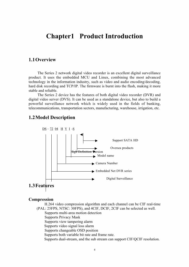
DS – 72 04 H V I -S
Support SATA HD
Oversea products
High Definition Version Model name
Camera Number
Embedded Net DVR series
Digital Surveillance

5
Storage:One SATA interface and the HDD can support up to 2000GB memory.HDD S.M.A.R.T. technologySupports FAT32 file systemSupports multiple record modes: schedule record, motion detection record,
external alarm record, motion & alarm record, motion or alarm record, manualrecord.
Supports cycle and none cycle record modes.Supports USB flash disk, USB hard disk and USB CD-RW/DVD-RW to
backup.Preview & Playback:
Supports one composite video output and one spot video output Series 2 can support one VGA output with 1204*768 resolution.
Supports VGA and VOUT output, VGA has precedence over VOUT, andcannot output at the same time.
Supports play forward, backward, pause, frame-by-frame, etc.User-defined preview layout.Supports one playback channel.
Network:Supports TCP, UTP, Multicast, DHCP, etcSupports RTP.Supports ADSL (PPPoE) dialup function.Remote parameters setupRemote download and playback the recorded filesRemote upgrade the DVR firmwareRemote PTZ controlSupports IE for network controlRemote alarm DVR information acquisition
Others:Supports network voice talk.Supports WATER MARKSupports local and remote PTZ control.Supports multi-level user management.Supports local and remote log searching functions.Automatic recovery from exceptions enables high reliability.Provides SDK and demo source codes for application development.

6
Chapter2 Installation
Warning: Before you install the DVR, please make sure that the power of DVR isswitched off.
2.1Checking the DVR and Its Accessories
When you get the product, check that all the goods are included in your productpackage. There is a list in the package. If any of the goods are missing, please contactyour dealer.
2.2HDD Installation
Installation noticeThere is no HDD in the DVR when leaving the factory. According to the record
schedule, you can calculate the total capacity you need (refer to Appendix A). Pleaseask the specialist to disassemble the DVR and install the HDD.
Installation instrumentOne “Phillips” or “Cross Head” screw driver
HDD installation1. Open the DVR box.2. Place the HDD on the mounting plate.3. Connect the ATA data cable correctly. First put the power plug of the HDD in
the motherboard. Plug the data line of the HDD into the SATA interface.4. Fix the HDD into the Chassis.5. Cover and fix the DVR box.
Note: After the HDD installation, you must format the HDD. Please refer tosection 6.3.

7
2.3Rear Panel Description
Fig. 2-1 Series 2 Rear panel
Note: Please refer to actual product for different models.SERIES 21. Video in 2. Video out 3.VGA interface 4. Alarm out 5. RS-485 T+ T- R+ R- 6. Power switch 7.USB interface 8. Audio in 9. Audio out 10. UTP interface 11. Alarm in 12.+12V DC power supply input

8
Chapter3 Operating Instructions
3.1 Front Panel Introduction
Fig. 3.1 Front panel introduction
Table 3.1 Items on front panel
Index Type Name Description
1 Lamp IR receiver.2 State
LampsPower
STATUSTx/Rx
Green means the DVR is working; Extinguish means theDVR is powered off;Green means the DVR is in SHIFT mode.Bright means the DVR is accessed by IE or ClientSoftware; Twinkle means the DVR is operating through IEor Client Software.
NumericKeys
Input number, lower case, upper case, character andsymbols.
9
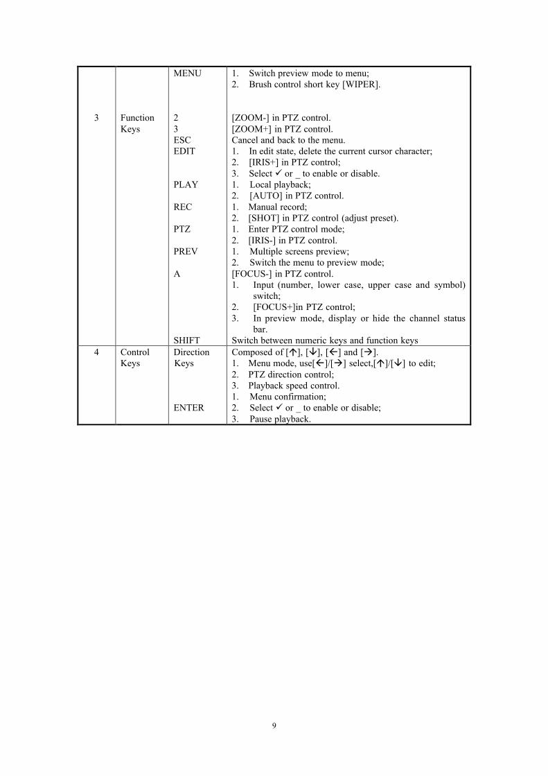
3 FunctionKeys
MENU
23ESCEDIT
PLAY
REC
PTZ
PREV
A
SHIFT
1. Switch preview mode to menu;2. Brush control short key [WIPER].
[ZOOM-] in PTZ control.[ZOOM+] in PTZ control.Cancel and back to the menu.1. In edit state, delete the current cursor character;2. [IRIS+] in PTZ control;3. Select or _ to enable or disable.1. Local playback;2. [AUTO] in PTZ control.1. Manual record;2. [SHOT] in PTZ control (adjust preset).1. Enter PTZ control mode;2. [IRIS-] in PTZ control.1. Multiple screens preview;2. Switch the menu to preview mode;[FOCUS-] in PTZ control.1. Input (number, lower case, upper case and symbol)
switch;2. [FOCUS+]in PTZ control;3. In preview mode, display or hide the channel status
bar.Switch between numeric keys and function keys
4 ControlKeys
DirectionKeys
ENTER
Composed of [], [], [] and [].1. Menu mode, use[]/[] select,[]/[] to edit;2. PTZ direction control;3. Playback speed control.1. Menu confirmation;2. Select or _ to enable or disable;3. Pause playback.

10
3.2 IR remote control
Fig. 3.2 Elevation of IR remote control
Table 3.2 Instruction of IR remote control
Index Name Description
1 POWER Turnoff device.
2 DEV Enable IR remote control
3 Numeric Keys Same as numeric keys of front panel.
4 EDIT Same as EDIT key of front panel.
5 A Same as A key of front panel.
6 REC Same as REC key of front panel.
7 PLAY Same as PLAY key of front panel.
8 Reserved _
9 Reserved _
10 MENU Same as MENU key of front panel.
11 PREV Same as PREV key of front panel.
12 Direction KeysENTER
Same as direction keys and enter keyof front panel.
13 PTZ Same PTZ key of front panel.
14 ESC Same as ESC key of front panel.
15 Reserved _
11
16 F1 Key for Extension.
17 Lens control IRIS, FOCUS ZOOM for lenscontrol.
18 F2 Key for spot video output.
Placing the batteries into the IR remote control1. Remove the battery cover.2. Insert the battery. Please make sure that the poles (+ and _) are correctly placed.3. Fold the battery cover.
Start to use IR remote controlSwitch the device power on, wait without any operations until preview screen
appears, and then you can use IR remote control to manage DVR on condition that thedevice ID is default “255”, which can be changed in “Display” menu.
If the default device ID has been changed, please press [DEV] key of the IRremote control, input the present device ID and then press [ENTER] key. Then youcan use the IR remote control to operate this DVR.
Stop using IR remote controlWhen the DVR is controlled by the IR remote control, press [DEV] key again,
then the IR remote control can not control this DVR.
Switch the DVR offWhen the IR remote control is working, press [POWER] key for several
seconds, then the power off prompt will pop up, press [Confirm] and switch off thepower on the rear panel manually.
When IR remote control can not work normally Check batteries poles. Check the remaining charge in the batteries. Check IR remote control sensor is masked. Please replace with another IR remote control and try again. If the problem still
exists, please contact administrator.
3.3 Menu Description
3.3.1 Menu Items
Table 3.3 Menu at a Glance
Menu Name Function Menu Name Function

12
Display
Device IDRequire passwordScreen saverVideo standardEnable scalerMenu transparencyDate/TimePreview
Camera
Select cameraNameColorDate OSDMotion Det. LevelAdvanced Settings
Recording
If HD FullSelect cameraStream typeResolutionFrame rateBit rateEnable RecPreRec timePostRec time
Network
IPPortMaskGatewayHttp PortAdvanced SettingsPPPoE
Alarms
Select Alarm In & Alarm TypeAlarm Handling & policy & PTZlinkageAlarm out & timeExceptions
PTZ
Select CameraBaud Rate & Data BitsStop Bits & ProtocolPTZ Add. & PresetSequence No. & Cruise
User
Add/DeletePassword/VerifyDefault PrivilegesSet Privileges
Utilities
Default parametersFirmwareHard DiskAlarm outputRebootPower offView logSystem information
3.3.2 Menu Operation
How to enter the menu mode Press [MENU] key to enter the DVR main menu. Press [PLAY] short key to enter the playback menu. Press [REC] short key to enter the manual record menu. Press [PTZ] short key to enter the PTZ control interface.
Note: You must input user name and password. The default user name is“admin” and password is “12345”.
Main Menu DescriptionThe main menu interface is shown as Fig.3.3 below:

13
Fig. 3.3 Main menu
There is one small frame named “Active Frame”. It can be moved from one item toanother by using direction keys ([_] [_]). When the “Active Frame” is located on oneicon, you can press the [ENTER] key to enter the sub menu. For example, move the“Active Frame” to “Camera” icon, press [ENTER] to enter the sub menu as followsFig.3.4 below:
Fig. 3.4 Camera input adjustment
Each menu contains different kinds of items. There is a small rectangular framenamed “Active Frame” which is pointing to the selected item. This “Active Frame”can be moved by direction keys ([_] [_] [_] [_]). There are several kinds of menu itemsas follows:
1. Check Box: Provides two options, “” means enable and “_” means disable.You can use [ENTER] or [EDIT] key to switch over.
2. List Box: Provide more than 2 options. Only one of them can be selected.After pressing [EDIT] you can use [_] and [_] to select one option. Forexample, on the right side of “Select Camera”, there is a list box for you toselect one camera.
3. Edit Box: This is for you to input characters. Press[EDIT]key to enter theedit status, you can input text there:
a) Press[A]key to select number, upper case, lower case or symbols;b) Use[_]and[_]keys to move the cursor;

14
c) Use[EDIT]key to delete the character in front of the cursor;d) Press [ENTER] to save & [ESC] to exit without saving.
4. Button: Trigger a special function or enter the next sub-menu. For example,press “Policy” button to enter the sub-menu. Press [Confirm] to saveparameters and return to the main menu. Press the [Cancel] button to canceland return to the main menu. The button in grey means it can be operatedonly after being enabled.
How to exit menuPress [PREV] key to exit menu and return to preview mode.

15
3.4 Input Text
In the menu interface, if in edit status (for example, in the “camera name” editbox), at the bottom of screen, the input status appears as follows:
Here it means you can press numeric keys to input digital number.Press [A] key to change input ways. You can select “number”, “Uppercase”,
“Lowercase” or “Symbol”.Uppercase
Lowercase
Symbol
There are 24 symbols in all. They are divided into 4 pages, and you can press the [0]key to turn over the pages.

16
Chapter4 Basic Operation Guide
4.1 Power on
Note: Please make sure that the power supply matches the DVR and the ACadapter is connected correctly. Before switching the DVR on, please connect onemonitor through the VOUT or VGA interface. Otherwise, you cannot see thegraphic user interface and operate the device.
If the [POWER] lamp is off, please follow the steps below:Step1: Connect the power supply correctly;Step2: Switch on the power button on the rear panel.
When DVR is started, The [POWER] lamp is green. If the HDD is not installedor detected, the information “No Disk A _” will be seen in the lower right corner ofthe preview screen.
4.2 Preview
DVR will enter the preview mode after started.On the preview screen, you can see the date, time, and camera name.Set the system date and time in “Camera” _ “Date OSD” menu, please refer to
5.5; Change camera name in “Camera” menu, please refer to 5.5On the screen, you will see the record and alarm status of each camera. Shown
as Fig.4.1 below, these two kinds of status will alternate automatically.Press [A] key to display or hide the camera status bar.
Fig. 4.1 Recording Status
Table 4.1 Camera record Status

17
Icon Icon Color Status Description
White No video signal
Yellow Video input
Pink Manual recording
Green Real time recording
Blue Motion detect recording
Red External alarm recording
Fig. 4.2 Alarm status
Table 4.2 Camera alarm status
Icon Icon Color Status Description
White Video signal loss
Yellow View tampering alarm
Pink Motion & External alarm
Green No alarm
Blue Motion alarm
Red External alarm
Press the numeric keys to switch the individual camera preview in SHIFT mode.

18
For example, you can press [2] key to preview 2nd camera.Press [EDIT] key to manual cycle preview. You can set the auto preview mode
in “Preview” menu, referring to 5.11.Press [PREV] key to switch multi-screens preview.

19
4.3 Video Spot Output
Make sure that the numeric button is in “function” mode (the status lamp is off) Press the[shift] button to switch the numeric button between “numeric” mode and “function”mode. Step1: Connect Video out 2 with monitor by a cable.
Step2: Press [3] to enter the spot out mode.Step3: Press [shift] to enter the numeric modeStep4: Press [1] to [4] button to switch the video spot output from channel 1 to
channel 4 Note: make sure that there is video signal input; otherwise spot out will be only shown as bluescreen.
4.4 User name and Password
Note: When DVR is delivered from factory, there is only one defaultadministrator named “admin”, and password is “12345”. The administrator’sname can not be modified, while the password can be modified. Theadministrator can create 15 users and define their rights.
LoginLogin dialog as shown Fig.4.3 below
Fig. 4.3 Login dialog
Use the []/ [] keys to select one user, press the [ ] key to enter “Password”edit box, input corresponding password, press [ENTER] key to exit edit box. The“Active Frame” will move to “Confirm” button. You can press the [ENTER] key toenter the main menu. If there is no response, it means the user name and password areincorrect. After three incorrect entries, the DVR will enter the preview mode.
Modify passwordFor those users created by admin, they can modify their passwords as follows:
Step1: Enter main menu

20
Press the [MENU] key, in the login dialog, select your user name, input thecorrect password, you will enter the main menu. As shown below.
Fig. 4.4 Input passwords
Fig. 4.5 Main menu
Step 2: Select the target user name by using [_],[_] then move the “ActiveFrame” to the “Password” icon by using[]/[ ]keys. As shown in Fig.4.6 below.
Fig. 4.6 Modify user’s password

21
Step 3: Input the new passwordUse the numeric keys to input the new password. The password can be null. It
also can be 16 numerals. Press [ENTER] to exit edit box, and move to “Verify” itemto verify password.
Note: In edit box, use [ ]/ [ ] to move the cursor and the [EDIT] key todelete the numeral in front of the cursor.
Step 4: Modify password successfully Move the “Active Frame” to “Confirm” button, press the [ENTER] key. If
the password is modified successfully, you will turn to the main menu. Or an errordialog will pop up. You can repeat step 3 to modify again.
4.5 PTZ Control
Note: The user must have the “PTZ control” right.
PTZ control interface
In menu mode, press the [PTZ] key, you can enter the PTZ control interfacedirectly.
In preview mode, press the [PTZ] key, in the login dialog, select one user nameand input the correct password, you can enter PTZ control interface. As shown inFig.4.7 below.
Fig. 4.7 PTZ Control interface
The position where the current camera name displays can be user-defined.
Select channelIn the PTZ control mode, you can press the numeric keys under SHIFT mode to
select the channel. For example, you can press the [2] key to select the 2nd cameraPTZ.
After you select the camera PTZ, you can use the control keys to control thePTZ.

22
PTZ control keys descriptionDirection control keys: [_], [_], [_], [_];ZOOM control keys: [ZOOM+], [ZOOM-];FOCUS control keys: [FOCUS+], [FOCUS-];IRIS control keys: [IRIS+], [IRIS-];Adjust preset keys: [REC/SHOT];Auto control key: [PLAY/AUTO];Wiper control key: [MENU/WIPER];Light control key: [F1/LIGHT];
Adjust preset descriptionIn PTZ control mode, press the [REC/SHOT] key, and press the preset number
(three numeric keys); The DVR will adjust to the corresponding preset numbers.Repeat pressing the [REC/SHOT] key, and press the preset number, The DVR willadjust to that preset number.
When you exit the PTZ control mode, the camera will stay at the currentposition.
Note: The PTZ preset number has been set already. Please refer to thePTZ menu for preset setup. V2.0 firmware can support 128 preset at most.
Start/Stop auto function in PTZ control modeIn the PTZ control mode, press the [PLAY/AUTO] key to start the PTZ auto
function. Press the [PLAY/AUTO] key again to stop.When the PTZ is in auto mode, if you exit the PTZ control mode, The PTZ will
continue auto function unless you enter the PTZ control mode again, and press the[PLAY/AUTO] key to stop.
Exit PTZ control modePress [ESC] or [ENTER] to exit and return to the preview mode.

23
4.6 Manual Record
Note: The user must have the corresponding right, DVR has HDD and HDD hasbeen formatted already.
Manual recordIn preview mode, press the [REC] key, in the pop-up login dialog, select the
name and input the correct password, you can enter the “Manual Record” interface.In menu mode, press the [REC] key to enter the “Manual Record” interface
directly.
Fig. 4.8 Manual record interface
Description The manual record interface has the following parts: channel number, channel
status, start/stop record, start all and stop all buttons.Channel: List the channel numbers the DVR has.Status: Channel work status has 4 cases: means idle. Green means the
channel is recording (including real time recording, alarm recording, motion detectionrecording). Red means network transmission. Orange means both recording andnetwork transmission.
Start/Stop: “ ” means you can start corresponding channel recording. “_”means you can stop recording.
Start All: Press this button to start all channels recording.Stop All: Press this button to stop all channel recording.Press the [ESC] key to enter the preview mode. Press the [MENU] key to enter
main menu. Press the [PLAY] key to enter the playback menu. Press the [PTZ] key toenter the PTZ control mode.

24
4.7 Playback
Note: The user must have “Playback” right.
Playback interfaceIn preview mode, press the [PLAY] key, in the pop-up login dialog, select the
user name and input the correct password, you can then enter the “Playback”interface.
In menu mode, press the [PLAY] key, you can then enter the “Playback”interface directly. Shown as Fig.4.9 below (The multiple screen play back functionmay be canceled, so the second channel option may not display)
Fig. 4.9 Playback interface
Description Select a Channel: Move the “Active Frame” to “Chan”, press “edit” button, thenuse [_] or [_] key to select a channel.
Rec Type: Use [_] or [_] to select the recorded file types. The file type optionshave “All”, “All Time”, “Motion Detect”, “Alarm” and “Manual”.
Time Section: You can define the search time section. Move “Active Frame” tothe time edit box; use the numeric keys to input the detail time.
Search: Search the matched recorded files and display them in the list box. Ifthere is not a matched file, a corresponding dialog box will be pop-up.
Play by Time: Playback the recorded stream directly based on the time section.Select Page: In the file list box, each page will only display 8 files. If the
matched files are more than 8, you can select page to list other files. 500 pages (4000files) can be searched in one time. You can use numeric keys or the [_] [_] keys toselect a page.
File List Box: List the matched files. File started time, file size are displayed inthe list box. You can use the [_] [_] keys to move the scroll bar to select file.
Backup Devices: You can select USB flash, USB HDD to backup the files orclips.
Copy: Start to backup.Backup Today: Backup all recorded files of today.

25
Operation during playback
Fig. 4.10 Playback interface
At the bottom of image, there is an information bar and the followinginformation is included: Volume, Play Progress, Play Speed, Played Time and FileTotal Time.
Display/Hide information bar: [MENU]Open/Close sound: [PLAY]Adjust play progress: [_] (Backward), [_] (Forward). The unit is “%”.Adjust play speed: Normal speed is “1x”. Use [_] to increase play speed (2X,
4X). Use [_] to decrease play speed (1/2X, 1/4X, 1/8X and single)Pause/Continue: Press [ENTER] to pause/continue playback. If played frame by
frame, Press [ENTER] to play one frame.Copy segment: [EDIT]; Stop copy: [EDIT] (Need a back up device to store the
segment)Exit: [ESC]Exit playbackIn playback interface, press the [ESC] key to enter the preview mode.In playback interface, press the [MENU] key to enter main menu, press the
[REC] key to enter the manual record, and press the [PTZ] key to enter the PTZcontrol mode.
Playback with mouse connectedIf you playback with a mouse connected, the interface will be a little different.
And you can acquire more functions to operate in the playback course which is shownas Fig.4.11 below.

26
Fig. 4.11 Play back control bar
There is an additional bar that appears. We call it the control bar.Control bar descriptions:
: You can click these buttons to skip backward or forward3% each time.
: You can click these buttons to select the play speed : Click this button to pause. : Click this button to mute, click it again to recover the sound. : Click this button to start copy the segment, click it again to
stop. : Click this button to hide the control bar, right click your
mouse and select display, then the control barwill turn up again.
: Click this button to trigger a rectangle area on the screen,draw the rectangle with left key of your mousepressed and move to the area you want to zoomin then double click left key to zoom in thatplace. Click left key again to return to theplayback interface.
: Click these buttons to switch to next or previous playbackchannels. It is useless if you only have one channel recorded at that time.

27
4.8 Backup Recorded Files
Note: The user must have the “Playback” right. Please connect the backupdevices before you start to backup.
In the playback interface, you can backup the recorded files.In the preview mode, press the [PLAY] key, in the login dialog, select the
username and input the correct password, you can enter the playback interface.In the menu mode, just press the [PLAY] key, you can enter the playback
interface directly.
Backup recorded files within the day
In the playback interface, move the “Active Frame” to the “Backup Today”button, press the [ENTER] key, All recorded files, within the day, on all channels willbe backed up to the storage device. A pop-up dialog will display the backup status.
If the backup device is not connected correctly or the DVR does not detect thebackup device, an exception dialog will pop up. Please ask administrator for moreinformation.
Backup the files that matched your requirement
Step 1: Search the matched filesIn the playback interface, select one channel and record type, input the time
section, move the “Active Frame” to the “Search” button, press the [ENTER] key,The DVR will start to find and list the matched files.
Step 2: Select the files that you want to backupIn the file list box, use the [_] or [_] keys to move the scroll bar. When the scroll
bar stays at the file you want to backup, press the [EDIT] key to select it. The symbol“” is the selection tag. You can use the same method to select other files you wantto backup. After you finish, you can follow the next step. Shown as Fig.4.12 below

28
Fig. 4.12 Playback list
Step 3: Select backup devicePlease confirm the backup device: USB flash memory, USB HDD and select the
corresponding backup device.Step 4: Start and finish backupMove the “Active Frame” to the “Save” button and press the [ENTER] key to
start the backup.When the backup is started, a corresponding message box will pop-up to
indicate the process.Backup video segmentYou can also backup the image segments during playback. The steps are:
1) Enter the interface of “playback the files or playback by time”;2) Press the [EDIT] key to start selecting the current playback image, and press
[EDIT] again to stop selecting. This segment is selected;3) You can repeat step 2 to select multiple segments. 30 segments can be
selected in all;4) After you select all segments, press the [ESC] key, a message window will
pop-up. If you press the “Confirm” button, the DVR will start to backup theselected segments. If you press the “Cancel” button, the DVR will abort thebackup.
Playback the video segmentYou can use our file player software to playback the video segment in your PC.
You can find the player software in the attached CD.Exit playback interface
Please refer to chapter 4.6.
4.9 Shut down DVR
Note: You can only turn off the power directly

29
Chapter5 Parameters Setup Guide
Only the users who have the “Parameters Setup” right need to read this chapter.When the following parameters are modified and saved, you must reboot the DVR tomake the new parameters become effective. Others do not need to reboot the device.
Any network parameters Resolution and record schedule External alarm sensor type View tampering alarm schedule Video loss alarm schedule Motion detection alarm schedule External alarm schedule Alarm output schedule
5.1Administrator and Password
When the DVR leaves from the factory, there is one default administrator. Thename is “admin” and password is “12345”. The name cannot be changed, while thepassword can be modified.
Password modificationPress the [MENU] key, in the login dialog, select the username as “admin”, use
the [_] key, move the cursor to the password edit box, input “12345”, press “Confirm”to enter the administrator menu.
Fig. 5.1 Enter user menu
Move the “Active Frame” to the “User” icon, press the [ENTER] key to enter the“User Management” menu. Shown as Fig.5.2 below

30
Fig. 5.2 User management
In the user name list box, only “admin” is exists. You can use the [_] key,move the “Active Frame” to the password edit box, and press the [EDIT] key to enteredit status. Press the numeric keys to input the new password. The password can be amaximum of 16 numerals. After you have finished inputting the password, you canpress the [ENTER] key to exit. Move the “Active Frame” to the “Verify password”edit box, input the same password as above to verify the password. Move the “ActiveFrame” to the “Confirm” button, and press [ENTER], if password and verifypassword are the same, the password will be saved and taken into effect.
If password and verify password are not same, a warning message box willappear. Shown as Fig.5.3 below
Fig. 5.3 ErrorIn this case, press [ENTER] to return to the password edit box, and input the new
password again.

31
d5.2 Add and Delete User
Enter the “User Management” interface.
Add user
The steps are as follows:Step 1: Enter the “User Management” menu as Fig.5.4 belowPlease refer to chapter 5.1
Fig. 5.4 user management
Step 2: Add new user nameIn the “User Management” menu, move the “Active Frame” to the “Add” button
and press [ENTER], in the pop-up dialog, input the new user name (refer to chapter3.4), press [ENTER] and return to the “User Management” menu. A total of 15 userscan be added. Shown as Fig.5.5 below
Fig. 5.5 Input user name
Step 3: Setup the password for new userAfter you add one new user, the password is null. You can skip this step if you do

32
not want to change the password.In the users list box of the “User Management” menu, use the [] [] keys to
select the new user name, then use the [] key to the password edit box. Press the[EDIT] key to enter edit box, use the numeric keys to input the new password.
Step 3: Setup the rights for new userThe new added user has no operational rights. You must setup rights for the user.In the users list box of the “User Management” menu, use the [] [] keys to
select the new user name, then use the [] key to the “Default Privileges” button,press [ENTER], the user will have the default rights. The default rights include localplayback, remote playback and view log.
If you want to define the detail rights, move the “Active Frame” to the “SetupPrivileges” button and press [ENTER] to enter the rights setup menu as follows:Shown as Fig. 5.6
Fig. 5.6 Set user right
Operational rights are divided into “Local” and “Remote”. You can assign thenecessary rights to the user. Use the [] [] keys to move the “Active Frame” to thecorresponding right items, press the [ENTER] or the [EDIT] key to enable or disablethe item. A “ ” means assign the right to that user.
Step 4: Save the new user’s password and rightsIn the “User Management” menu, press the “Confirm” button, the user’s
password and rights will be saved and you will return to the main menu. If you pressthe “Cancel” button, the configuration will be abandoned.
User rights description
“Local”:Local rights are for local operation, such as the operation using front panel, IR
remote control and RS-485 interface.PTZ control: Locally control PTZ;Record: Manual start/stop recording;Set parameters Setup: Locally setup the DVR parameters;Log: Locally view the log on DVR;Utilities: Locally upgrade firmware, format HDD, reboot DVR and shut down
33
DVR, etc.
“Remote”:PTZ Control: Remote control PTZ;Record: Remote manual start/stop recording;Set parameters Setup: Remote setup the DVR parameters;Log: Remote view the log on DVR;Utilities: Remote upgrade firmware, format HDD, reboot DVR and shut down
DVR, etc.Talk: Client talks with DVR;Alarm: Remote control DVR alarm output;Local Video Out: Remote control DVR video output;Com Control: DVR RS-232
MAC address
This MAC address is not the address of the DVR but the address of the PC thataccesses the DVR. If you setup this function, only the PC with this MAC address canaccess this DVR.
At the PC end, in the DOS prompt, you can use the “ipconfig” command to getthe PC MAC address (6 bytes).
Delete user
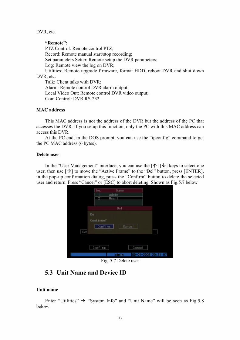
In the “User Management” interface, you can use the [] [] keys to select oneuser, then use [] to move the “Active Frame” to the “Del” button, press [ENTER],in the pop-up confirmation dialog, press the “Confirm” button to delete the selecteduser and return. Press “Cancel” or [ESC] to abort deleting. Shown as Fig.5.7 below
Fig. 5.7 Delete user
5.3 Unit Name and Device ID
Unit name
Enter “Utilities” “System Info” and “Unit Name” will be seen as Fig.5.8below:

34
Fig. 5.8 System Info
There is an item named “Unit Name”. The default unit name is “Embedded NetDVR”. Move the “Active Frame” to unit name edit box, press the [EDIT] key to enteredit status, you can modify the unit name. Please refer to chapter 3.4 about how toinput characters. You can press the [ENTER] key to finish the modification. Selectthe “Confirm” button and press [ENTER]; you can save the new unit name and makeit effective. Press the “Cancel” button or the [ESC] key to abort the modification.
Device ID:
Fig. 5.9 Display menu
When using the IR remote control to operate the DVR, you must use the deviceID to select the DVR. The default device ID of the DVR is “88”. If there is more thanone DVR in one place, please define different device ID’s for each DVR. Otherwise,the IR remote control will control all DVR’s with the same device ID at the sametime.
In “Display” menu, move the “Active Frame” to the device ID edit box, in the

35
edit status, you can use the numeric keys to input the new device ID. The device IDvalue is ranged between1-255.
After you finish the modification, press the “Confirm” button to save and takeeffect or press “Cancel” to abort the modification.

36
5.4Video Output Standard
Video output standard
There is one VOUT BNC connector at the rear panel of the DVR. It is used toconnect with the analog monitor and can support PAL or NTSC video output. Youcan modify the video output standard to match the video input.
In “Display” menu: There is a list box named “Video Standard”, you can use the[] [] keys to select PAL or NTSC video output.
Press “Confirm” button to save or “Cancel” to abort.

37
5.5Camera name and OSD Setup
Camera NameIn the “Camera” menu, you can define the name for each camera. Please notice
that the camera’s name cannot be copied. Shown as Fig.5.10 below
Fig. 5.10 Input camera number
The steps of camera name setup:Step 1: Select one camera.Step 2: Move the “Active Frame” to the camera name edit box, press the
[EDIT]key to enter edit status, you can input digital numbers, uppercase andlowercase characters (refer to Chapter 3.4). The camera name can support 32characters.
Step 3: Press the [ENTER] key to exit edit status.Move the “Active Frame” to the “Confirm” button, press [ENTER] to save the
modification and you can see the new camera name. Press the “Cancel” button or the[ESC] key to abort.Camera Name Position
If you do not want to display the camera name, just disable the check box besidecamera name edit box. The disable flag is “_”. If you enable the check box, you cansetup the camera name position. You can copy the position to any other camera. Thesetup steps are:
Step 1: Enter the “Camera” menu.Step 2: Select one camera.Step 3: Enable the check box on the right side of camera name, then you move
the “Active Frame” to the “Position” button, press[ENTER]to enter camera nameposition setup interface, as in the picture below, in that interface, you can use the[][][][]keys to move the camera name position. When the position is fixed,press [ENTER] and return to the “Camera” menu, and press the “Confirm” button tosave it. In the “Image Setup” menu, press the “Cancel” button or [ESC] key, you canabort the modification.
OSD is an abbreviation of “On Screen Display”. For our embedded DVRDVS, itincludes displaying the system time and camera name.
The OSD settings include: System time, time format, time display position,camera name, camera name display position, etc.

38
System TimeIn the “Display” menu, you can setup the DVR system date and time.Move your active frame to the “Date/Time setup” item, and press enter.Date Display Mode: Move the active frame to the Date Display Mode then press
[EDIT] then use the [_] [_] keys to select the OSD format. There are the followingOSD formats:
MM DD YYMM DD YYYY MM DDYY MM DD Here YY means year, MM means month, DD means day.You can also enable the DST (Daylight-saving Time) function here. Shown as
Fig.5.11 below
Fig. 5.11 Date/time setup
Date OSD PositionIn the “Camera” menu you can adjust the position where you want the Date to
display, move the active frame to the “Position” item on the right side of the “DateOSD” item and press the [ENTER] button. Then you will see the picture below. Use[_] [_] [_] [_] to adjust the position of the date. As Shown:
Fig. 5.12 Set Positions of Data & Time

39
5.6Video Parameters Setup
For different cameras and different backgrounds, in order to get the best videoimage, you need to adjust the video parameters such as brightness, saturation, contrastand hue, etc.
You can setup the cameras individually, and you can also copy the videoparameters of one camera to any of the other cameras. Here are the setup steps:
Step 1: Enter “Camera”, select a camera then enter the “Color setup” menu.Shown as Fig.5.13 below
Fig. 5.13 Color setup
Step 2: Select camera: Please use the [] [] keys to select one camera.
Step 3: Adjust brightness, contrast, saturation and hue: Move the “Active Frame”to the “Adjust” button on the right side of Brightness, Contrast, Saturation and Hue,press the [ENTER]key, you will enter the corresponding adjustment interface. In theadjustment interface, there is one scroll bar at the bottom, you can use the [] []keys to adjust and the video image will be changed at the same time. When you aresatisfied with the real time video image, press [ENTER] to return to the “Color”menu.
Step 4: You can copy the video parameters of a current camera to any othercamera. Or you can repeat setp2 and step3 to adjust for any other camera.
After adjusting, in the “Image Setup” menu, press the “Confirm” button to savethe parameters and make them become effective. Otherwise, press the “Cancel”button or the [ESC] key to abort the modification.

40
5.7Mask Area Setup
In some cases, you might want to mask the sensitive area. This area will not bepreviewed and recorded. The mask area setup steps are as follows:
Step 1: Enter the “Camera” menu:Step 2: Select one camera: You can use the [] [] keys to select one camera.Step 3: Enter the “Advanced settings” enable the check box beside the “Privacy
Mask” item, you can press the [Enter] or the [edit] key to change the flag into a “”,and the active “Area” button. Move the “Active Frame” to the “Area” button on theright side of mask check box, press the [ENTER]key to enter mask area setupinterface. Shown as Fig.5.14 below
Fig. 5.14 Mask area setup
Step 4: Setup the mask area: In the mask area setup interface, there is one smallyellow pane on the upper left side. For a PAL camera, the whole screen is divided into22*18 panes (22*15 for NTSC), you can use the [_][_][_][_]keys to move the yellowpane to your hope position and press[EDIT]key, the yellow pane will be turned intored, then you can use[_][_][_]keys to extend the red pane and the [_]key to shrink thered pane. This red area is the mask area.
After the red mask area is selected, press the [EDIT] key to save the mask area.The maximum mask area size is 8*8 panes and the minimum size is only one pane.You can setup 4 mask areas at most.
After you finish the setup, press the [ENTER] key to return to the “Advancedsettings” menu. You can press the [A] key to clear all mask areas.
Step 5: Save mask area: You can repeat step2, step3 and step4 to setup the maskarea for other cameras. In the “Advanced setting” menu, press the “Confirm” buttonto save the mask area, press the “Cancel” button to abort.
Here is the example for the mask area function. Shown as Fig.5.15 below

41
Fig. 5.15 Area masked
Disable the mask check box to cancel the mask area.

42
5.8View Tampering Alarm
If you enable this function, when someone blocks the camera spitefully, TheDVR will display a warning alarm in the status bar on the screen.
Step 1: Enter the “Camera” menu:
Step 2: Select a camera: Please use the [] [] keys to select one camera.And enter the “Advanced Settings”.
Step 3: Select sensitivity: Move the active frame to the sensitivity item rightbeside the “View tampering” item. Press the [edit] key, then you can use the [_] [_]keys to select the sensitivity for the “View Tampering” item. The sensitivity optionsare: Low, Normal and High. Select one of them to activate the “Area Setup” and“Policy” configuration.
Step 4: View tampering area setup Move the “Active Frame” to the “Area”button, press the [ENTER] key to enter area setup interface. The setup methods arethe same as that of the mask area setup [See 5.7]. After setting the area, press the[ENTER] key to return to the “Advanced settings” menu. You can press the [ESC]key to abort.
Note: Only one view tampering area can be setup, and the size of the areacan be full screen.
Step 5: View tampering alarm setup In the “Advanced settings” menu, movethe “Active Frame” to the “Policy” button, press the [ENTER] key to enter the “ViewTampering Handle” menu: Shown as Fig.5.16 below
Fig. 5.16 View tampering handle setup
Step 6: Alarm schedule setup: When a tampering alarm happens, the DVRwill handle the alarm based on the schedule. You can set 4 periods for each day of theweek. You can also copy the schedule of one day to other days.
Note: Time periods can not be repeated. Please reboot DVR to make the

43
parameters become effective.
Step 7: Setup alarm policy: If a tampering alarm happens in the schedule, theDVR will response based on the policy. You can select one or more solutionsincluding: “On Screen Warning”, “Audible Warning”, “Upload to Center” and“Trigger Alarm Output”. You can use the [_] [_] keys and the [EDIT] key to enable ordisable them. “_” is disable and “” is enable.
Step 8: Save alarm setup: After your setup, press the “Confirm” button andreturn to the “Image Setup” interface. In the “Image Setup” menu, press the“Confirm” button to save current camera parameters and return to the main menu.
Step 9: Save all cameras: If you want to setup other cameras, please repeatstep2 to step 8. In the “Image Setup” menu, press the “Confirm” key to save allcamera parameters. Press the “Cancel” button or the [ESC] key to abort.
If you select the “Off” option for “View Tampering”, you can delete the viewtampering area.
Note: Only one view tampering area can be setup for each camera. Theview tampering area can not be copied. If the schedule is modified, you mustreboot the device to make the parameters become effective.

44
5.9Video Loss Alarm
When the video cable or camera malfunctions, the video image is lost. If youenable video loss alarm, in such a case, the DVR will display the alarm in the statusbar on the screen.
Step 1: Enter “Camera” menu:Step 2: Select camera: Use the [] [] keys to select one camera.Step 3: Enter the “Advanced settings” interface: Move the “Active Frame”
to the handle method box on the right side of “Signal Loss” item, use the [] key toselect the “Handle” option and move the “Active Frame” to the “Policy” button on theright side. Press [ENTER] to enter the “Signal Loss” interface: Shown as Fig.5.17below
Fig. 5.17 Video signal loss handle setup
Step 4: Setup alarm schedule: You can setup a working schedule. Only whenthe video loss happens within the schedule, will the DVR respond.
Note: The 4 time periods cannot be repeated. Please reboot the DVR to makethe parameters become effective.
Step 5: Setup alarm policy: You can select one or more response solutions,including: “On Screen Warning”, “Audible Warning”, “Upload to Center” and“Trigger Alarm Output”. You can use the [_] [_] and the [EDIT] keys to enable ordisable them. “_” is disable and “” is enable.
Step 6: Save alarm setup: After your setup, press the “Confirm” button andreturn to the “Advanced setting” interface. Press the “Confirm” button to save currentcamera parameters and return to the main menu.
Step 7: Save all cameras: If you want to setup other cameras, please repeatfrom step2 to step 6. In the “Camera” menu, press the “Confirm” key to save allcamera parameters. Press the “Cancel” button or the [ESC] key to abort.

45
5.10 Motion Detection
If you enable this function, when motion is detected, the DVR will displayalarm in the status bar on the screen.
Step 1: Enter the “Camera” menu:
Step 2: Select camera: Use the [ ] [] keys to select one camera afterpressing the [edit] key.
Step 3: Select motion detection sensitivity: On the right side of the “MotionDet. Level” item, there is a list box. That is the motion detection sensitivity. There are7 options, from 0 (the lowest) to 5 (the highest) and “Off”. You can use the [_] [_]keys to select one. If you select the “Off” option, the DVR will not respond even ifthere is motion detection. If you select other options, it will activate the “Motion AreaSetup” button and the “Policy Setup” button. If you select low sensitivity such as 0,the DVR will respond only when there is a great amount of motion detected. On theother side, for high sensitivity such as 5, the DVR will respond, even if there is asmall amount of motion detected.
Step 4: Motion area setup: You must define motion areas so that the DVR willrespond when there is motion in those areas. Move the “Active Frame” to the “Area”button on the right side of sensitivity list box, press the [ENTER] key, you can enterthe “Motion Area Setup” interface. Show as Fig.5.18 below.
Fig. 5.18 Motion area setup
The whole screen is divided into 22*18 panes (NTSC: 22*15). There is oneyellow panel on the upper left side. The motion area setup steps are the same as thatof the mask area setup (refer to chapter 5.7). The only difference is that you can usethe [PTZ] key to set the whole screen as a motion area, and multi motion areas can bedefined. Press the [A] key to clear all motion areas.
Setup multi areas: After you setup one motion area, press the [EDIT] key, theyellow pane will appear again, and then you can setup another motion area.

46
Clear part of motion area: Move the yellow pane to the start clear position ofmotion area, press [EDIT], you will find the yellow pane is turned into a black pane.You can use the [_] [_] keys to enlarge or shrink the blue area. Press the [EDIT] keyto clear this part motion area.
Press the [Enter] key to save and return to the “Image” menu. Press [ESC] tocancel.
Clear all motion areas: Press the [A] key to clear all motion areas of thischannel.
The keys used to setup motion areas are following: [_][_][_][_]: Move yellow panel to any position; [EDIT]:Yellow panel and red panel switch key:; [_]: Right enlarge red pane; [_]: Left shrink red pane; [_]: Down enlarge red pane; [_]: Up shrink red pane; [PTZ]: Set whole screen as motion area; [A]: Clear all motion areas; [ENTER]: Save and return “Image Setup” menu; [ESC]: Cancel setup and return “Image Setup” menu;
Step 5: Motion alarm policy: Move the “Active Frame” to the corresponding“Policy” button of the motion detection alarm, press the [ENTER] key to enter the“Motion Alarm Handle” menu: Shown as Fig.5.19 below
Fig. 5.19 Motion alarm handle setup
Step 6: Motion alarm record channel setup: When there is a motion alarmthat happens, you can trigger the related camera to start to record. In the “MotionAlarm Handle” menu, you can select one or more record channels. Please use[ENTER] or the [EDIT] key to enable the flag into a “”.
Note: In order to make the cameras start recording, in the “Recording”menu, you must enable the recording schedule and set the “Rec Type” as“Motion Detection” or “Motion | Alarm”. Please refer to chapter 5.12 forrecording setup.

47
Step 7: Motion alarm schedule: When the motion alarm happens in theschedule, the DVR will respond with messages such as “On Screen Warning”,“Audible Warning”, “Upload to Center” and “Trigger Alarm Output”. You can setup4 time periods for one day and 7 days for one week.
Note: Time periods in one day can not be repeated.
Step 8: Motion alarm handle method setup: You can select one or morehandle methods such as “On Screen Warning”, “Audible Warning”, “Upload toCenter” and “Trigger Alarm Output”.
Note: If the “On Screen Warning” is enabled, when the motion alarmhappens and the DVR is in preview mode, the DVR will switch to the relatedcamera. If you trigger more than one camera, the DVR will display them one byone every 10 seconds. When the motion alarm stops, the DVR will restorepreview mode.
Step 9: Save motion alarm setup: Press the “Confirm” button to return to the“Image Setup” menu. In the “Image Setup” menu, press the “Confirm” button to savethe current camera parameters.
Step 10: Save all cameras: You can repeat from step2 to step8 to setup themotion detection parameters for other cameras. You can also copy the parameters ofone camera to any other cameras.
Note: Motion alarm area can not be copied.
If you want to disable the motion alarm area and motion alarm policy, yousimply need to select the motion alarm sensitivity as “Off”.
5.11 Preview
After the device starts, the preview screen will be seen; then you can press the“PREV” key to switch between one screen and four screens; You can also switch tothe other single screen by pressing “EDIT”; or in “SHIFT” mode you can pressnumeric keys to switch to the screen number you want.
In the “Preview” menu, you can setup preview mode, screen switch time, enableor disable audio preview and preview layout.
Step 1: Enter “Preview” menu: In the main menu, move the “Active Frame”to the “Display” icon and press [ENTER], then go to the “Preview Setup” and press[ENTER], you can enter the “preview” menu. Shown as Fig.5.20 below

48
Fig. 5.20 Setup preview mode
Step 2: Preview properties:
Preview mode: For preview mode item, you can use the [_] [_] keys to selectone mode. If the DVR has 4 channels, there are “1 Screen” and “4 Screen” options. Ifthe DVR has more than 4 but less than 9 channels, there are “1 Screen”, “4 Screen”and “9 Screen” options. If the DVR has 16 channels, there are “1 Screen”, “4 Screen”,“9 Screen”, “12 Screen” and “16 Screen” options.
Switch time: This is the screen preview switch time. You can use the [_] [_]keys to select the switch time. There are many options, including “5 Seconds”, “10Seconds”, “20 Seconds”, “30 Seconds”, “1 Minutes”, “2 Minutes”, “5 Minutes” and“Never”. If you select “Never”, the preview screen will not be switchedautomatically. For example, for a 16 channel DVR, if you select “4 Screen” previewmode and “20 Seconds” switch time, the DVR will cycle and display 4 channels onthe screen every 20 seconds.
Audio preview: If you enable the audio preview (“”), when you preview asingle camera, the DVR will play the audio of that channel.
Preview layout setup: There is a square frame divided into many windows. Ifyou select “4 Screen” preview mode, this frame is divided into 4 windows. Eachwindow represents one camera. You can move the “Active Frame” among thewindows. There is one bar under the square to display the preview order of allcameras.
First select the biggest screen preview mode, for example, for a 4-channel DVR,select “4 Screen” preview mode so that all the windows are displayed in the square.
Secondly, move the “Active Frame” to one of these windows; press the numerickeys to input the camera index. The small window will display that camera number.In this way you can change the display order. If you press 0, then the correspondingwindow will not display live video.
After you define the camera preview order, you can select preview mode tomeet your demand.
Save setup: Press the “Confirm” button to save preview properties. Press“Cancel” or the [ESC] key to abort.

49
5.12 Recording Setup
In main menu, there is an icon named “Recording”. You can enter the recordingmenu as follows:
Fig. 5.21 Recording channel configuration
“Recording” menu description:
If HDD Full: There are two options: “Overwrite” and “Stop recording”. If youselect the “Overwrite” option, when all HDDs in the DVR are full, the DVR willoverwrite the earliest recorded files and continue recording. If you select the “Stoprecording” option, when all HDDs are all full, the DVR will handle it as the “HardDisk Full” exception, please refer to chapter 5.17 for the exception menu.
Select Camera: Here all channels are listed. You can use the [_] [_] keys toselect one.
Stream Type: There are two options, one is “Audio&Video” stream and theother is “Video” stream only. If you want to record video and audio, please select the“Audio&Video” option, otherwise you can select the “Video” option to record onlyvideo. For DS-8000HSI DVR, there is only one “Video” option.
Note: If you change this option, please reboot the DVR to make theparameter become effective.
Resolution: The higher the resolution is, the clearer the image is. The resolutionoptions range from low to high and are: QCIF, CIF, 2CIF, DCIF, and 4CIF.
Note: If you change this resolution option, please reboot the DVR to make itbecome effective.
Bit rate: You can select the bit rate size for a fixed bit rate type. It is the sameas “Max Bit Rate”.
Frame Rate: Frames per second. Options are: 25 (PAL)/30 (NTSC) 20, 16,15_ 12, 10, 8, 6, 4, 2, and 1 for low frame rates, you can select low bit rate size.
Prerecord Time: When you enable motion detection recording or externalalarm recording, you can define the prerecord time. The options are: No Prerecord, 5Seconds (default selection), 10 Seconds, 15 Seconds, 20 Seconds, 25 Seconds, 30

50
Seconds and Max Prerecord.MaxPreRecord is to save all data in the Prerecord buffer. The Prerecord time is
related with the bit rate. The lower the bit rate, the longer the Prerecord time is.If the bit rate (Max bit rate) is very low, and you select “Prerecord Time” as “5
Seconds”, The actual prerecord time may be more than 5 seconds. On the other hand,if the bit rate is high, and the set “Prerecord Time” is “30 Seconds”, the actualprerecord time may be less than 30 seconds.
Post Record Time: When the external alarm or motion alarm is stopped, theDVR will continue recording time. The options are: 5 Seconds (default), 10 Seconds,30 Seconds, 1 Minute, 2 Minutes, 5 Minutes and 10 Minutes.
Enable Rec: Enable or disable the selected camera record function. “_” meansdisable and “” means enable.
Schedule: When you enable the recording function, you can setup a recordingschedule.
Note: When the camera recording schedule is modified, you must rebootthe DVR to make it become effective.
All day recording setup:Step 1: Enter recording schedule menu
In the recording menu, use the [ENTER] or the [EDIT] key to enable the recordfunction (“” flag), press the “Schedule” button to enter the recording schedulemenu.
5.22 Recording schedule setup
Step 2: Select one day and enable all day recording optionsFor the “Day” item, there are options: Monday, Tuesday, Wednesday,
Thursday, Friday, Saturday and Sunday. Use the [_] [_] keys to select one day. Movethe “Active Frame” to the check box on the right side of the “All Day” item, press the[ENTER]or the [EDIT] key to enable the “All Day” option. “_” means disable and“” means enable.
Step 3: Record typeFor the “Rec Type” item, the options are: All Time, Motion Detect, Alarm,
Motion | Alarm, and Motion & Alarm, command.

51
For all day record mode, only one record type can be selected.
Step 4: Copy to other daysYou can repeat step2 and step3 to setup for other days. You can also copy the
current day to other days.
Step 5: SavePress “Confirm” to go back to the “Recording” menu. Press “Confirm” again to
save the parameters and return to the main menu.
Part time recording setup
Step 1: Enter recording schedule menuIn the recording menu, use the [ENTER] or the [EDIT] key to enable the record
function (“” flag), press the “Schedule” button to enter the recording schedulemenu.
Step 2: Select one day and disable the all day recording optionFor the “Day” item, there are options: Monday, Tuesday, Wednesday,
Thursday, Friday, Saturday and Sunday. Use the [_] [_] keys to select one day. Movethe “Active Frame” to the check box on the right side of the “All Day” item, press the[ENTER]or the [EDIT] key to disable the “All Day” option. “_” means disable and“” means enable.
Step 3: Setup the time period and record typeThere are 4 time periods for one day, and each time period can select a different
record type. Input the start time and stop time for each time period, and select therecord type for each period. The record type options are: All Time, Motion Detect,Alarm, Motion&Alarm and Motion | Alarm, command.
Note: The time periods in one day can not be repeated.
Step 4: Copy to other daysYou can repeat step2 and step3 to setup for other days. You can also copy the
current day to other days.
Step 5: SavePress “Confirm” to go back to the “Recording” menu. Press “Confirm” again to
save the parameters and return to the main menu.Note:
1) If the record type is “Motion Detect” or other related types, you must setup“Motion Detection” in order to trigger motion recording (refer to chapter5.10).
2) If the record type is “Alarm” or other related types, you must setup“Alarms” in order to trigger alarm recording (refer to chapter 5.13).
3) The time periods are between 00:00 and 24:00.
5.13 External Alarm Input and Relay Output
For the Series 2 DVR, there are 4 alarms in and 1 relay out. In the “Alarms”menu, you can setup each external alarm input.

52
In the main menu, move the “Active Frame” to the “Alarms” icon and press the[ENTER] key to enter the alarms menu: Shown as Fig.5.23 below
5.23 Alarms setup
External alarm input setup:
Step 1: Select one alarm input Use the [_] [_] keys to select one alarm input.
Step 2: Alarm typeThis is the sensor type. You can select “Normal Open” or “Normal Close”
according to the sensor type.
Step 3: Enter “Alarm in Handling” sub menuIn the “Alarms” menu, there are two options for the “Alarm Handling” item. One
is “Ignore”, and the other is “Handle”. If you select the “Handle” option, you canactivate the “Policy” and “PTZ Linkage” buttons on right side. Move the “ActiveFrame” to the “Policy” button and press the [ENTER] key, you will enter the “Alarmin Handling” sub menu: Shown as Fig.5.24 below
Fig. 5.24 Alarm in handling setup
Step 4: Alarm trigger record channel setup

53
You can select channels to record for each alarm input. In the sub menu, youcan use the [ENTER] or [EDIT] keys to enable the record channel. “_” means disableand “ means enable.
Note: In order to trigger the channel to record, in the “Recording” menu,you must enable recording and select the record type as “Alarm” or otherrelated types. Please refer to chapter 5.12.
Step 5: Schedule for alarm handle methodWhen an external alarm happens in the schedule, the DVR will respond
according to the handle methods.
Step 6: Alarm handle methodYou can select one or more handle method: “On Screen Warning”, “Audible
Warning”, “Upload to Center” and “Trigger Alarm Output”.
Note: If “On Screen Warning” is enabled, when there is an external alarmthat happens and the DVR is in preview mode, the DVR will pop-up the relatedcamera. If you trigger more than one camera, the DVR will display them one byone every 10 seconds. When the external alarm disappears the DVR will restorepreview mode.
Step 7: Save setupIn the “Alarm in Handling” sub menu, press the “Confirm” button and return to
the “Alarms” menu. In the “Alarms” menu, press the “Confirm” button to save theparameters.
Step 8: PTZ LinkageMove the “Active Frame” to the “PTZ Linkage” button, press the [ENTER] key
to enter the “PTZ Linkage” setup menu: Shown as Fig.5.25 below
Fig. 5.25 PTZ linkage setup
First select one camera, and then select one of following PTZ linkages: Preset: Set the flag as a “” to enable the preset, in the preset number edit
box and input one preset number that has been setup already. Please refer tochapter 5.15 for preset setup.
Sequence: Set the flag as a “” to enable sequence and input one sequencenumber that has been setup already. Please refer to chapter 5.15 for sequence

54
setup. Cruise: Set the flag as a “” to enable cruise. Please refer to chapter 5.15 for
cruise setup.Press the “Confirm” button to save and return to the “Alarms” menu. Press the
“Cancel” button or the [ESC] key to abort and return to the “Alarms” menu.Note: Please make sure that the PTZ you are using can support preset,
sequence and cruise functions. One external alarm input can trigger manycameras PTZ linkage.
Step 9: Copy the parameters to other external alarm input, you can copy theparameters of a current alarm input to another external input.
Step 10: Save setup In the “Alarms” menu, press the “Confirm” button to savethe parameters. Press the “Cancel” button or the [ESC] key to abort.
Alarm relay output setup
Step 1: In the “Alarms” menu, use the [_] [_] keys to select one alarm output.
Step 2: Select delay timeThe delay time is when the alarm disappears; the alarm output will continue
output time. The delay time options are: 5 Seconds, 10 Seconds, 30 Seconds, 1Minute, 2 Minutes, 5 Minutes, 10 Minutes and Manual Stop. If you select the“Manual’ option, the alarm output will not stop until you press the “Clear Alarm”button in the “Utilities” menu. So the actual alarm output time is made up of alarminput time and this delay time.
Step 3: Enter alarm out scheduleYou can set the schedule to enable the alarm output. Move the “Active Frame”
to the “Schedule” button on right side of “Alarm Out Time” item, press the [ENTER]key to enter the corresponding schedule menu: Shown as Fig.5.26 below
Fig. 5.26 Alarm out schedule
Step 4: Setup alarm out scheduleLike the other schedule setups, you can set 4 time periods for one day and 7
days for one week. When you finish the setup, press the “Confirm” button to return tothe “Alarms” menu.

55
Step 5: Copy one alarm output parameters to other alarm outputIn the “Alarms” menu, you can copy parameters of a current alarm output to
another alarm output.
Step 6: Save setupWhen you finish the setup, in the “Alarms” menu, press the “Confirm” button to
save all parameters.Note: If any schedule is modified, you must reboot the DVR to make it
become effective.
ExceptionsThe exceptions can be handled include: hard disk full, hard disk error, illegal
access, IP address conflict, network failure, and NTSC/PAL differ.Enter “Exceptions” menu: Shown as Fig.5.27 below
Fig. 5.27 Exceptions setup
Including the following handle methods:Audible Warning: Beeping.Upload to Center: Send exception information to center host PC.Trigger Alarm Output: trigger local relay output.You can select more than one handle method.
After you finish the setup, press the “Confirm” button to save parameters. Pressthe “Cancel” button or the [ESC] key to abort.

56
5.14 Network Parameters
If you want to use a network to access the DVR, you must setup the networkparameters.
Note: If any network parameter is modified, you must save and reboot theDVR to make it become effective.
In the main menu, move the “Active Frame” to the “Network” icon and press[ENTER], you can enter the “Network” menu as follows: Shown as Fig.5.28 below
Fig. 5.28 network setup
“Network” menu description:
IP address: This IP address must not conflict with another IP on the network. Ifthere is DHCP server in the network, you can set the IP as “0.0.0.0”, save and rebootthe DVR. In the reboot process, the DVR will search for the DHCP server and get adynamic IP address. This item will display the dynamic IP address. The DVR can alsouse the PPPoE function, the DVR can dial up to the internet and this item will displaythe dynamic internet IP address.
Port: Network access port number, must be greater than 2000.Mask: This is the sub net mask.Gateway: The gateway IP is used to communicate in different network
segmentsHttp Port: The port is for the IE browser. The default value is 80. It can be
modified.Advanced settings: Move the “Active frame” to “Advanced settings” then
press “enter” to enter the configure interface. Shown as Fig.5.29 below

57
Fig. 5.29 Advanced network setup
Advanced setup descriptions:Mac: The physical address of the device, which can not be written.NIC type: Default is “10M/100M Auto”, the other options are: 10M Half-Dup,
10M Full-Dup, 100M Half-Dup and 100M Full-Dup.IP server address: If the DVR uses the PPPoE function, it will get one
dynamic IP address. If you set a DNS IP with one fixed Internet IP, the DVR willsend some information such as the DVR name, DVR serial number, DVR current IPto that fixed IP address. We -call that a fixed Internet IP as DNS IP. The DNS serverwith that fixed Internet IP can receive the DVR information and use it to resolve theDVR dynamic IP. This IP server is special software, not the normal domain nameserver. You can use the provided SDK to develop this DNS software.
Multicast IP: It is one D-class IP address, among 224.0.0.0 ---239.255.255.255. If you do not use the multicast function, you do not need to set it up.Some routers will prohibit multicast functions in case of a network storm.
Remote Host IP and Port: If you set this IP and port, when there is an alarm orexception that happens, the DVR will send information to that host IP. The centerwith this IP, can receive alarm and exceptions information from the DVR. You canuse SDK to develop this center software.
DDNS: This stands for dynamic domain name service.Instructions on DDNS are provided below
PPPoE: The DVR supports PPPoE dial-up functions. As Fig.5.30 shown below:

58
Fig. 5.30 PPPoE setup
Example: Use PPPoE function
Step 1: Enter “Network” “Advanced Settings”.
Step 2: Select NIC type.
Step 3: Input the port number. In the port edit box, use the numeric keys toinput the port number. The port number must be more than 2000.
Step 4: Input IP Server: Input one fixed Internet IP address where the IPanalyst software (IP Server) is run.
Step 5: Enter the PPPoE Setup & Input the PPPoE parameters. Use the[ENTER] or the [EDIT] key to enable the PPPoE function (set PPPoE flag as “√”).Input the PPPoE username, password and verify the password that your ISP provided.
Step 6: Save parameters. In the “Network” menu, press “Confirm” to save theparameters. Reboot the DVR to make the parameters effective. In the reboot process,the DVR will start dialup using the PPPoE function. If the DVR accesses the internetsuccessfully, the DVR will display the dynamic internet IP address in the “Network”menu.
Using the DDNS function:
Step 1: From the “Main Menu” move the “Active Frame” to the “Network”button and press [ENTER] this will bring up the “Network” screen
Step 2: Move the “Active Frame” to the “Setup” button next to DDNS and press[ENTER]
Step 3: Enable the DDNS function by changing the “x” to a “check mark”; Thiswill enable the DDNS features as follows:

59
Protocol: This is a protocol such as “DynDNS”. This is just the name of the webservice providing your Dynamic DNS.
Server Address: When using the “DynDNS” service, your server address will be(members.dyndns.org). As more services for dynamic DNS become availablefor the DVR, the addresses will be different for different services.Server Port: Unless there is a specific server port you need to use, keep theserver port at 0.
Hostname: Your host name will be something such as:myoffice11.dyndns.org. You can set your hostname when filling out theinformation with the DyDNS service.
Username: This is your username for the login with your DyDNS service.
Password: This is your password for the login with your DyDNS service.
Verify Password: This is your same password for your login with yourDyDNS service.
Step 4: Save the parameters by pressing the “Confirm” button, or press “Cancel” toabort.
5.15 PTZ
There is one RS-485 port at the DVR rear panel used for the PTZ control. Youcan setup the RS-485 parameters to match your PTZ protocol. In the main menu, youcan move the “Active Frame” to the PTZ icon and press the [ENTER] key, you can

60
enter the PTZ menu as follows: Shown as Fig.5.31 below
Fig. 5.31 PTZ parameters setup
PTZ menu description
Select camera: Select one PTZ camera.
RS-485 parameters: Including baud rate, data bit, stop bit, parity, flow control,etc. These parameters must be the same as those PTZ protocols.
PTZ address: Each PTZ has one different address.
PTZ type: The DVR has the following PTZ protocols: YouLi, LinLin-1016,LinLin-820, Pelco-p, DM DynaColor, HD600, JC-4116, Pelco-d WX, Pelco-D,VCOM VC-2000, NetStreamer, SAE/YAAN, Samsung, Kalatel-312, CELOTEX,TLPelco-p, TLHHX-2000, BBV, RM110, KC3360S, ACES, ALSON, INV3609HD,Howell, Tc Pelco P, Tc Pelco D, AUTO-M, AUTO-H, ANTEN, CHANGLIN,DeltaDome, XYM-12, ADR8060, EVI-D30, DEMO-SPEED, DM-PELCO-D, ST832,LC-D2104, HUNTER, A01, TECHYIN, WEIHAN, LG, D-MAX, Panasonic, KTD-348, infinova, PIH-7625, LCU, DennarDome, etc. Other PTZ protocols will be addedwith the new firmware.
Note: In the DVR “PTZ” menu, if you select Pelco-P protocol, when yousetup the PTZ address, please use a plus or minus one compared with CameraID. For example, if camera ID is 2, the DVR PTZ address is set as ID 3.
Preset setup: Preset is using one number to represent the camera’s position,zoom, focus and iris. Move the “Active Frame” to the “Setup” button on the right sideof the “Preset” item, press the [ENTER]key to enter the preset setup menu. You cansave 128 preset numbers. Please make sure the PTZ supports the preset functionbefore you setup a preset.
Sequence setup: Each sequence is made up of several cruise points. Each cruisepoint includes one preset number, dwell time and dwell speed. Please make sure thePTZ you are using can support the sequence function before you start to setup. Youcan save 16 sequences.

61
Cruise setup: Cruise is remembering the track of the PTZ movement. Pleasemake sure the PTZ you are using can support the cruise function.
Preset setup
In the “PTZ” menu, move the “Active Frame” to the “Setup” button on the rightside of the “Preset” item, press[ENTER], you can enter the “Preset” setup menu:Shown as Fig.5.32 below
Fig. 5.32 PTZ preset setup
Add preset number: You can input a preset number (among 1~128) in the editbox. Then press the “Adjust” button to enter the PTZ control interface. In the PTZcontrol interface, you can use the direction keys to adjust the PTZ position, and use[IRIS+] [IRIS-] [FOCUS+] [FOCUS-] [ZOOM+] [ZOOM-] keys to adjust iris, focusand zoom. After you have finished adjusting, press [ENTER], then press the “Save”button to save the preset number. You can repeat this step to setup other presetnumbers.
After you setup all preset numbers, press the “Return” button to return to the“PTZ” menu. In the “PTZ” menu, press the “Confirm” button to save all parameters.
Delete preset number: In the “Preset” setup menu, input one preset number,press the “Delete” button, you can delete this preset number.
After deleting, press the “Return” button to return to the “PTZ” menu. In the“PTZ” menu, press the “Confirm” button to save all modifications.
Please make sure the PTZ you are using can support the preset function.
Sequence setup
In the “PTZ” menu, press the “Setup” button on the right side of the “SequenceNo” item, you can enter the “Sequence” setup menu: Shown as Fig.5.33 below

62
Fig. 5.33 PTZ sequence setup
In the “Sequence” setup menu, first input the sequence number. The sequence isamong 1 --- 16. Each sequence is made up of cruise points, and each cruise pointincludes a preset number, dwell time and dwell speed. Dwell time is the time stayingat that preset number. Dwell speed is the speed that the PTZ is moved to that presetnumber.
Press the “Add” button to add one cruise point.Press the “Confirm” button to save the cruise point into the sequence.After you finish the setup for the sequence number, press “StartSeq” to check the
current sequence. Press the “Stop” button to stop checking.You can delete cruise points in one sequence.
After you finish the sequence setup, press the “Return” button to return back tothe “PTZ” menu. In the “PTZ” menu, press the “Confirm” button to save themodification.
Please make sure the PTZ you are using can support the sequence function.
Cruise setup
In the “PTZ” menu, press the “Setup” button on the right side of the “Cruise”item, you can enter the “Cruise” setup menu: Shown as Fig.5.34 below
Fig. 5.34 Cruise setup

63
Press the “Rec Cru” button, you will enter the “PTZ control” interface. You canstart controlling the PTZ with direction keys, press [ENTER] to save the operationtrack and return to the “Cruise” setup menu. Press the “StartCru” button to repeat thePTZ track until you press the “Stop” button.
Press the “Return” button back to “PTZ” menu. In “PTZ” menu, press the“Confirm” button to save this cruise.
Please make sure the PTZ you are using can support the cruise function.

64
Chapter6 Utilities
There are many tools in the “Utilities” menu. Including “Default Parameters”,“Firmware”, “Hard Disk”, “Alarm Out”, “Reboot”, “Power Off”, “View Log” and“System Information”.
Enter “Utilities” menu: Shown as Fig.6.1 below
Fig. 6.1 Utilities
6.1 Restore Parameters
Restore factory parameters for the DVR. The IP address, gateway and portnumber will not be restored. Shown as Fig.6.2 below
Fig. 6.2 Restore parameters

65
6.2 Upgrade
You can use this function to upgrade the firmware. Please confirm the languageis matched. Press the “Upgrade” icon, in the pop-up dialog, you can select either “FTP” or“USB” upgrade mode. Shown as Fig.6.3 below
Fig. 6.3 Upgrade
If you select “FTP” mode, you will enter “FTP Upgrade” menu:
Fig. 6.4 FTP IP setup
Please Input the ftp server IP and press the [ENTER] key. DVR will connectwith FTP server through network and download the firmware file.
If you select “USB” mode, please make sure you connect one USB flashmemory with DVR and the firmware file is in its root directory.
Reboot after successfully upgrading, the system will use the new firmware.

66
6.3 Hard Disk Management
Fig. 6.5 Hard Disk setup
Check HDD work statusCapacity, Free space, Stand by or not, Normal status or not.
Format HDDBefore formatting, stop all recording. After formatting, you must reboot the
DVR; otherwise the DVR will not work normally.
6.4 Stop Alarm Out
Clear the alarm output manually.
6.5 Reboot
Reboot DVR.
6.6 Power off
Shut down DVR.
6.7 View Log
To view the log recorded in the DVR HDD.In the “Utilities” menu, press “View Log” to enter the “Log” menu: Shown as
Fig.6.6 below

67
Fig. 6.6 View log
If you want to view the log based on the default option, just press the [ENTER] key.The DVR will list all matched information. Also you can select options to search (ByType, By Date, and By Type & Date).
By Type
View the log information by the assigned type.Type is divided into “Major type” and “Minor type”. Major type includes
operation, alarm, exception and all.For operation major type, there are many minor types, including Power On,
Shut Down, Abnormal Shut, Panel Login, Panel Logout, Panel Config, Panel FilePlay, Panel Time Play, Local Start Record, Local Stop Record, Panel PTZ, PanelPreview, Panel Set Time, Local Upgrade, Net Login, Net Logout, Net Start Record,Net Stop Record, Net Start Transparent Channel, Net Stop Transparent Channel, NetGet Parameter, Net Config, Net get Status, Net Alert On, Net Alert Off, Net Reboot,BiComStart (Start Voice Talk), BiComStop (Stop Voice Talk), Net Upgrade, Net FilePlay, Net Time Play, Net PTZ.
For alarm major type, the minor type includes: External Alarm In, ExternalAlarm Out, Motion Detect Start, Motion Detect Stop, View Tamper Start and ViewTamper Stop. For the exception major type, the minor type includes: Video Signal Loss, IllegalAccess, Hard Disk Error, Hard Disk Full, IP Conflict and DCD Lost.
For example: The steps of viewing alarm log.
Step 1: For the “Query” item, select “By Type” to activate the “Major Type”and “Minor Type” items.
Step 2: For the “Major Type” option, select the “Alarm” option. For the “MinorType” option, select one of following options: All, External Alarm In, External AlarmOut, Motion Detect Start, Motion Detect Stop, View Tamper Start, and View TamperStop.
Step 3: Move the “Active Frame” to the “Search Log” button, press the[ENTER] key to start searching.

68
Step 4: When the searching is finished, the DVR will list all matched alarminformation. In the list box, the information includes: Index, Occur Time, MajorType, Minor Type, Panel User, Net User, Host Address, Parameters Type, ChannelNo, HDD No, Alarm In and Alarm Out. You can press the “More Info” button formore information. You can also select a page number to view more information.
Step 5: Press the “Return” button to return back to the “Utilities” menu.
By Time
View the log of one period.
Step 1: Select “By Time” for the “Query” option to activate the “Start Time”and “Stop Time” items.
Step 2: Input the start time and stop time.
Step 3: Move the “Active Frame” to the “Search Log” button and press the[ENTER] key to start searching.
Step 4: After you have finished searching, the DVR will list the matched loginformation.
Step 5: Press the “Return” button to return back to the “Utilities” menu.
By Type & Date
View one kind of log in the assigned time period.
Step 1: Select “By Type & Time” for the “Query” option to activate the “MajorType”, “Minor Type” “Start Time” and “Stop Time” items.
Step 2: Select “Operation” for major type and select one option for minor type.
Step 3: Input the start time and stop time.
Step 4: Move the “Active Frame” to the “Search Log” button and press the[ENTER] key to start searching.
Step 5: After you have finished searching, the DVR will list the matched loginformation.
Step 6: Press the “Return” button to return back to “Utilities” menu.

69
6.8 System Information
Press the “System Info” icon in the “Utilities” menu; you can get the DVRsystem information: Shown as Fig.6.7 below
Fig. 6.7 System information
70
Chapter7 Firmware Upgrade
The DVR firmware is stored in FLASH ROM. You can use the DVR upgradefunction to write the firmware file (digicap) into the FLASH.
There are two cases that you need to upgrade the DVR firmware. One is to updateold firmware. The other is when the code in the DVR FLASH has crashed.
Note: Make sure that the DVR and the firmware are compatible beforeproceeding with the upgrade.
7.1 Upgrade Mode
1. Use the client software to upgrade the firmware file. You do not need to usethe ftp server software. Please refer to the client software user manual fordetailed information.
2. Use the “FTP” function of the “Upgrade” sub menu in the “Utilities” menu.You need one host PC to run the FTP server software and place the firmwarefile (digicap), and make sure the DVR and the PC are in the same sub net.Refer to section 7.1 for more details.
3. Use the “USB” function of the “Upgrade” sub menu in the “Utilities” menu.Please make sure the firmware file (digicap) is placed under the rootdirectory of USB flash memory.
7.2 FTP Server Setup
Step 1: Setup wftp32 FTP server
Open the wftp32 software, as shown in Fig 7.1

71
Fig 7.1
Set the user and its rights, as shown in Fig 7.2
Fig 7.2
Click the “New User” button, create a user named “target”, set its password.And then choose it in the “User Name” drop down list. Input the path where thefirmware is placed in the “Home Directory” box (Here we placed it under the rootpath of Disk F. So we input “F :\”) then click “Done” to finish the setting of thewftp32 FTP server. As shown in Fig 7.3
Fig 7.3
Step 2: Upgrade

72
Enter the “Utilities” menu of the main menu, shown as Fig 7.4
Fig 7.4
Enter the “Firmware” item, shown as Fig7.5
Fig7.5
Choose update mode as FTP, shown as Fig 7.6
Fig 7.6
Input the FTP Server’s IP Address(The IP of the computer where wfp32 runs),

73
as shown in Fig 7.7, and press “Enter” to start upgrading, as shown in Fig 7.8
Fig 7.7
Fig 7.8
After the upgrade is completed, the system needs to reboot, as shown in Fig 7.9.Press “Confirm” to start the reboot process or press “Cancel” to reboot later. The newfirmware will start to work after rebooting.
Fig 7.9

74
Appendix A Mouse Control Function
1. Preview interface
Double-click the left key1. Switch to the channel where the arrow at when viewing single picture.2. Back to previous multi-pictures when double click again.
Scroll wheel forwardSwitch to previous screen
Scroll wheel backwardSwitch to the next screen
Single-click the right keyPop up function menu including “Main Menu” “Single 1-4ch” “Multi Preview
4 Screen” “Next Preview” “PTZ Control” “Play” “Manual Record” “Close Status”and “Aux Chan 1-4ch”.
2. PTZ interface
Double-click the left keyMove to the center of the screen (For SAE\YAAN protocol)
Drag the left keySelect an area to zoom in (For SAE\YAAN protocol)
Single click the left keyIf you select an area for zooming in this action, this will save the position as
No.60 and zoom in the area (For SAE\YAAN protocol)Scroll wheel forward
Switch to previous channelScroll wheel backward
Switch to the next channelNote: Using the mouse can only call the first 96 of the 128 presets.
3. Channel name or OSD position configure interface
Drag the left keyA rectangle frame will be following with the cursor
Single click the right keyPop-up menu including Confirm, Cancel (and Style for OSD only).
4. Area configure interface
Right clickPop-up menu including Confirm, Cancel, Clear, and Full (this option onlyappears in motion detect area configuration)
Drag the left keyExtend or shrink area

75
MovingThe primary grid will be following with the cursor
5. Test input interface
Click the left key1. Pop up soft keyboard2. Input text3. Save and exit
Click the right keyCancel the text and exit the edit mode
Scroll wheel forward or backwardCursor goes to the previous or next character
6. Playlist interface
Click the left keySelect the file to copy or cancel
Scroll wheel forwardSelect the previous file
Scroll wheel backwardSelect the next file
Signal-click the right keyCancel and return back to the preview interface.
Double-click the left keyPlay the selected file
7. User interface
Double-click the left keyEnter the selected user’s privileges setting interface
Single-click the right keyCancel the operations you did and back to previous interface
Scroll wheel forwardSelect previous user
Scroll wheel backwardSelect next user

76
Appendix B HDD Capacity Calculation
Calculate the total capacity needed by each DVR according to video recording(video recording type and video file storage time).
Step 1: According to Formula (1) to calculate storage capacity iq that is thecapacity of each channel needed for every hour, unit Mbyte.
102436008 ÷×÷= ii dq (1) In the formula: id means the bit rate, unit Kbit/sStep 2: After the video time requirement is confirmed, according to Formula (2)
to calculate the storage capacity im , which is the storage of each channel needed unitMbyte.
im = iq _ ih _ iD (2)In the formula:
ih means the recording time for each day(hour)
iD means number of days for which the videoshall be kept
Step 3: According to Formula (3) to calculate total capacity (accumulation) Tqthat is needed for all channels in the DVR during scheduled video recording.
∑=
=c
iiT mq
1 (3)
In the formula: cmeans total number of channels inone DVR
Step 4: According to Formula (4) to calculate total capacity (accumulation)Tq that is needed for all channels in DVR during alarm video recording (including
motion detection).
∑=
=c
iiT mq
1_a% (4)
In the formula_a% means alarm occurrence rate

77
Appendix C DVR Connect Cable
Definition
1 RS-485 connection methods There are R+, R-, T+, and T- on the RS-485 interface. R+, R- here are for receivingsignals, while T+, T- here are for sending signals.
2 UTP network connection method, Materials, and tools One twist cable (8 pin, the length can be defined as to the actual demand, but mustbe within 100m), 2 standard RJ45 head, one tool for RJ45.Suggestion: have a network cable test tool to test each cable made.
Pin definitionTo make the network cable according to the actual situation, there are two
options:(1) Use the following method to make the network cable when DVR is
connected with network hub or switch.
The corresponding relationship of the direct cable
(2) Use the following method to make the cross network cable when the DVR isdirectly connected with client-end PC.

78
The corresponding relationship of cross cable

79
Appendix D Specifications
Model Series 2
Video compression H.264Preview resolution PAL: 704_576 ; NTSC: 704_480 VGA: 1024*768Playback resolution QCIF/CIF/2CIF/DCIF/4CIFVideo input 4 channels, BNC (1.0Vp-p, 75_)Video output 1 channel, BNC (1.0Vp-p, 75_) Video spot output 1 channel, BNC (1.0Vp-p, 75_)
Frame rate (perchannel)
4CIF: 6fpsDCIF: 12fps2CIF: 15fps
CIF: 25(P)/30(N) fpsAudio compression OggVorbis, 16Kbps
Audio input 1 channel, RCA (2.0~2.4Vp-p, 1K_)
Audio output 1 channel, RCA (2.0~2.4Vp-p, 600_)Stream type Video/Video&AudioSupport dual stream YesBit rate 32Kbps ~ 2Mbps, user-defined HDD interface 1 SATA interface can support 1 SATA HDD up to 10 TBCommunicationinterface
1 RJ45 10M/100M self-adaptive Ethernet Interface1 RS-485 interface
USB interface 1 USB interface can support USB disk, USB HDD, USB CD-RW &DVD-RW.
VGA interface 1 VGA interface can support resolution:1024*768/60Hz
External alarm in 4Relay output 1Voice talk 1 channel,(Using Audio IN)Support Buzzer YesPower supply 12VDCPower consumption ≤40W (without HDD or DVD-R/W)Operating temperature -10_ ~ +55_Relative humidity 10% ~ 90%Size 315(W)*230(D)*45 mm(H)Weight ≤2.8Kg (without HDD or DVD-R/W)PAL: 176_144(QCIF), 352_288(CIF), 704_288(2CIF), 528_384(DCIF), 704_576(4CIF);NTSC: 176_120(QCIF), 352_240(CIF), 704_240(2CIF), 528_320(DCIF), 704_480(4CIF).

80
Appendix E Troubleshooting
Failure Possible reasonsAfter plugging in power, turning on the power switch,“POWER” light in front Panel does not turn on, and fandoes not work.
1) Power cable malfunction.2) Power supply malfunction.
After plugging in power, turning on the power switch,“POWER” light in front panel turn to green while fan doesnot work.
1) Front panel cablemalfunction.
2) Fan malfunction.After plugging in power, turning on switch, “POWER”light turn to green, the indicator lights in the panel turn onat the same time, but fan does not work.
The ATX plug in main board isnot well plugged in.
DVR continuously reboots after starting up every 10seconds.
1) Upgrade the wrong firmware2) Compression board has
problems.3) Main board has problems.
There are no images in the monitor connected with VOUTafter DVR is started.
1) The cable connected with themonitor is malfunctioning.
2) Rear board of DVR hasproblems.
3) Main board of DVR hasproblems.
Cannot find the hard disk in reboot process. 1) Hard disk cable malfunction.2) The power cable of hard disk
is not connected.3) Hard disk malfunction.
DVR can not control PTZ through RS-485 port. 1) RS-485 cable i s notconnected correctly or ismalfunctioning.
2) PTZ parameters error.3) RS-485 port of DVR is
malfunctioning.Client software can not view DVR live image. 1) Network is error.
2) Connect wrong DVR (wrongIP, port number, username orpassword, etc).
3) Old player SDK (playm4.dll)
Note:1) Place the DVR in well ventilated space so that it operates within the allowedrange of temperature and humidity as in the specifications2) If the circuit board is wet, dust on circuit board can cause a short circuit. Thecircuit board, plug and socket, housing fan and housing should be cleaned by brushingregularly.

81
Appendix F Customer Information Card
User’s Name Mr./Mrs.
Company Name
Post Address
Postcode
Phone Number
Model Number
of Product
Serial Number
of Product
Purchase Date
Distributor

82
Suggestions:


![Meridian 204 User Manual400].pdf · About this manual, 1 Conventions used in the manual, 1 About the 200-Series, 1 Unpacking your 204 tuner, 1 Accessories, 1 Installing your 204 Tuner,](https://img.pdfslide.net/doc/110x75/5bf2f61309d3f2de488b9f32/meridian-204-user-400pdf-about-this-manual-1-conventions-used-in-the-manual.jpg)


![Silencing, consultation and indigenous descriptions … › wzukusers › user-23664162 › ...(2012) Series C No 245 (Inter-American Court of Human Rights) [204]. 4. Jennifer Hornsby,‘Disempowered](https://img.pdfslide.net/doc/110x75/5f16c963ab50a4184524ce83/silencing-consultation-and-indigenous-descriptions-a-wzukusers-a-user-23664162.jpg)