Embed Size (px)
Citation preview

April 2018 Edition
SERIES 20FR16 FITTINGS GUIDE
FIBERBOND® SERIES
•20FR16
•20FR16-C
ENGINEERED COMPOSITE PIPING SYSTEMS
www.fiberbond.com
www.futurepipe.com

2
FIBERBOND® Engineered Composite Piping Systems
April 2018 Edition - Series 20FR16, 20FR16-C
FIBERBOND® Fittings Guide - Series 20FR16 and 20FR16-C
PIPE SERIES: The fittings contained in this book are available in the following series (unless otherwise noted):
20FR16 16bar rated product for seawater, cooling water, and other high pressure lines, with fire endurance properties.
20FR16-C Identical to 20FR16, except it has an electrically conductive exterior for use where grounding is required.
GASKETS: 1. In systems hydrotesting above 225psig (15.5bar), gaskets with better sealing
properties, such as Garlock’s “Stress Saver” gasket (www.garlock.com), CTG’s “ET Energizer” gasket (www.ctgasket.com) or Asahi’s “Low Torque” gasket (www.asahi-america.com), are recommended for sizes 2” (50NB) and larger.
2. O-ring gaskets may also be used, but they do require a special o-ring groove to be machined in one face (and only one face) of the mating pair of flanges. O-ring gaskets have no takeout. Shore "A" hardness values are typically between 55 and 75. A typical material is Buna-N (NBR). For higher temperatures and resistance to certain acids and solvents, Viton® is also available. Viton® is a fluoroelastomer manufactured by DuPont Dow.
3. In systems hydrotesting between 150psig (10.3bar) and 225psig (15.5bar), either full-face 1/8” thick flat rubber gaskets (neoprene, red rubber, etc.) or gaskets with better sealing properties may be used in sizes 2” (50NB) and larger.
4. In systems hydrotesting only up to 150psig (10.3bar), full-face 1/8” thick rubber gaskets are recommended. Shore "A" hardness values can range from 60 to 80, although values down to 50 may be suitable as well as higher values.
5. These gasket recommendations do not take into account the required corrosion resistance of the systems. Make sure that gasket materials are suitable for the intended services. CR (neoprene) is normally good for water and seawater and has excellent weathering resistance. SBR (red rubber) is normally good for water, seawater, alcohol, glycol, and weak acids. NBR (Buna-N) is normally good for water, seawater, dilute acids, and aliphatic hydrocarbons (propane, butane, petroleum oil, mineral oil, grease, diesel fuel). EPDM (ethylene-propylene-diene rubber) is a good choice for hot water service, many solvents and many acid services.
RULES FOR O-RING GASKETS: 1. Takeout of the gasket is essentially zero inches. The gasket is 3/16" (0.1875", 4.8mm) nominal diameter and the groove is 0.15" (3.8mm). With compression of the gasket, the takeout is zero. 2. A groove is only provided in one face of each mating pair of flanges. The #1 situation to avoid with the o-ring gasket is a grooved flange mated directly to another grooved flange. The only solution to this situation is 1) remove one of the grooved flanges and replace with a flat-face flange, 2) fill one of the grooved flanges with a putty

3
FIBERBOND® Engineered Composite Piping Systems
April 2018 Edition - Series 20FR16, 20FR16-C
material to obtain a flat-face, or 3) insert a rubber gasket or harder material between the two grooved flanges along with an o-ring gasket in each groove to provide a suitable seal. 3. Other general rules that are usually followed with o-ring gaskets:
A. For FRP to FRP flange connection, the groove is placed in one of the FIBERBOND® flanges at the discretion of the fabricator. For convenience during installation, if the flange is in the vertical, the groove is normally placed in the lower flange.
B. For connections to alloy flanges, the groove is applied to the FIBERBOND® flange. There is only one exception to this rule and that is when the alloy flange is a drilled-and-tapped blind flange supplied by the fabricator. In this case, the groove is applied to the alloy blind flange.
C. For connections to full-face flanged valves, lug type valves, or wafer valves that do not have an integral seal, a groove is applied to the FIBERBOND® flange.
D. For connections to valves with integral seals (not seats), as is typical with many butterfly valves, no groove is applied to the FIBERBOND® flange as no gasket is used.
E. For connections to raised face flanges, an o-ring groove is not needed. A full-face 1/8" (3mm) thick rubber gasket, such as red rubber “SBR” can be used. The takeout for the gasket is 1/8" (3mm).
F. O-ring grooves are not applied to FIBERBOND® flanges smaller than 2" (50mm) diameter. If the connection is not to an alloy blind flange that can be “grooved” by the fabricator, then a full-face 1/8" (3mm) thick rubber gasket can be used.
G. For flange to blind flange connections, normally the groove is placed in the blind flange. Blind flanges are usually slightly less expensive to “groove” than flanges.
FLANGES: 1. All flanges are flat face and should be bolted to flat face flanges. FIBERBOND®
flanges can be bolted to raised-face flanges, however, care should be taken when torqueing these flanges. Over-torqueing can cause cracking in the flange.
2. The flange thickness will differ from ANSI B16.5 150#. 3. The outside diameter and bolt pattern will match 150#. Other bolt patterns, such as
300# and BS4504 PN10 & PN16, can be provided. The flange will still be limited to its standard pressure and temperature rating.
4. Reducing flanges are also available.

4
FIBERBOND® Engineered Composite Piping Systems
April 2018 Edition - Series 20FR16, 20FR16-C
NUTS, BOLTS, & WASHERS: 1. There are no special requirements for bolting materials except that ANSI B18.21.1
Narrow "SAE" series washers must be used. ANSI B18.21.1 Wide "USS" washers will not fit on FRP flanges.
LATERAL WELDS AND FITTINGS: 1. Lateral welds are currently only rated for design pressures up to 100psig (6.9bar) up
to 16in. (400mm) diameter and 50psig (3.4bar) for larger sizes. If higher pressures are required, please consult with Specialty Plastics.
CERTIFICATIONS AND APPROVALS: Series 20FR16 ABS 00 NO 32171-X, USCG 164.141/22/0 Series 20FR16-C ABS 00 NO 32171-X, USCG 164.141/23/0
ANSI DIMENSION FITTINGS: ANSI dimension flanged fittings are available upon request, but are rated only to 150psig (10.3bar). Please consult Specialty Plastics for information on these fittings.
VICTAULIC CONNECTIONS: For most pipes up to 12in. nominal diameter, ends can be machined to fit a victaulic coupling. Please consult Specialty Plastics for information on these fittings.
VPDMS, PDS, and AutoCAD CATALOGS: A catalog for Aveva Inc.'s 3D modeling software VPDMS is available by contacting Specialty Plastics (www.fiberbond.com). A 2-D catalog is also available for Autodesk's AutoCAD. A general catalog is also available for Intergraph's PDS, but there are some minor deviations in pipe O.D.s and flange neck lengths.
SPECIAL NOTES ON DRAIN SYSTEMS: Slopes can be fabricated in FIBERBOND® systems at any angle. When shop prefabrication work is performed by Specialty Plastics, laterals can be fabricated at special angles, such as 45.9 degrees (for a 3/16" sloped header). This eliminates the need for any special dimensioning. The same is true for tees and reducing tees. In sloped systems, elbows are normally kept at their full sweep for 45 or 90 degrees and the pipe is mitered to maintain the slope in the header.

5
FIBERBOND® Engineered Composite Piping Systems
April 2018 Edition - Series 20FR16, 20FR16-C
WALL THICKNESSES & OUTSIDE DIAMETERS: All FIBERBOND® Fiberglass Piping Series are manufactured with a fixed inside diameter. As the pressure rating of the pipe series increases, the wall thickness and outer diameter also increase.
Ratings, Wall Thicknesses, and Outside Diameters
Size 20FR16 and 20FR16-C
Rating I.D. THK POD Weight
(psig) (bar) (in.) (mm) (in.) (mm) (in.) (mm) (lb/ft) (kg/m)
1" 232 16.0 1.00" 25.4 0.25" 6.4 1.50" 38.1 1.0 1.5
1.5" 232 16.0 1.50" 38.1 0.25" 6.4 2.00" 50.8 1.3 1.9
2" 232 16.0 2.00" 50.8 0.31" 7.9 2.62" 66.5 1.5 2.2
2.5" 232 16.0 2.50" 63.5 0.25" 6.4 3.00" 76.2 1.9 2.8
3" 232 16.0 3.00" 76.2 0.25" 6.4 3.50" 88.9 2.2 3.3
4" 232 16.0 4.00" 101.6 0.25" 6.4 4.50" 114.3 2.9 4.3
5" 232 16.0 5.00" 127.0 0.25" 6.4 5.50" 139.7 3.9 5.7
6" 232 16.0 6.00" 152.4 0.25" 6.4 6.50" 165.1 4.3 6.4
8" 232 16.0 8.00" 203.2 0.32" 8.1 8.64" 219.5 7.8 11.6
10" 232 16.0 10.00" 254.0 0.39" 9.9 10.78" 273.8 11.0 16.4
12" 232 16.0 12.00" 304.8 0.46" 11.7 12.92" 328.2 16.3 24.3
14" 232 16.0 14.25" 362.0 0.54" 13.7 15.33" 389.4 20.8 31.0
16" 232 16.0 16.25" 412.8 0.62" 15.7 17.49" 444.2 27.9 41.6
18" 232 16.0 18.25" 463.6 0.69" 17.5 19.63" 498.6 33.7 50.2
20" 232 16.0 20.25" 514.4 0.76" 19.3 21.77" 553.0 40.0 59.6
24" 232 16.0 24.25" 616.0 0.91" 23.1 26.07" 662.2 57.3 85.4
30" 150 10.3 30.25" 768.4 0.73" 18.5 31.71" 805.4 59.3 88.3
36" 150 10.3 36.25" 920.8 0.87" 22.1 37.99" 964.9 84.9 126.4
42" 100 6.9 42.25" 1073.2 0.67" 17.0 43.59" 1107.2 77.0 114.7
48" 100 6.9 48.25" 1225.6 0.77" 19.6 49.79" 1264.7 100.1 149.2
54" 50 3.4 54.25" 1378.0 0.44" 11.2 55.13" 1400.3 64.5 96.0
60" 50 3.4 60.25" 1530.4 0.48" 12.2 61.21" 1554.7 79.1 117.8
1. Sizes 2.5", 5", and 54" are non-standard and are not as readily available as the standard sizes.

6
FIBERBOND® Engineered Composite Piping Systems
April 2018 Edition - Series 20FR16, 20FR16-C
CHANGES FROM THE PREVIOUS EDITION April 2018: Clarified note on when it is acceptable to use 1” as the minimum pup length. Corrected units error for the POD of Fig.1 pups. Added note about weight of dummy legs. September 2017: No dimensional changes. Added notes to clarify manufacturing methods for tees, reducing tees, laterals and reducing laterals. April 2016: Revised statement about <=2” gaskets at 435psig (30 bar) hydrotests in the Gaskets section to match the Gasket Selection document. Wall thickness and OD for the 2” size corrected to match our other documents. November 2014: Combined flanges and blinds into one section. Moved bleed rings, vanstone flanges and Fig.19MH/MC blinds to the Special Fittings Guide. Removed Fig.80F3. January 2013: Added note on flange neck lengths. Added note on the pigmented exterior of fittings and flanges (in the Elbows section). Updated FOD for the 2" size. June 2012: Updated weights for the 14x12 and larger reducing laterals (Fig.88). January 2012: Updated the drawing for Fig.47JF MNPT olet; added note on gaskets. April 2010: Updated the available reducing tee sizes. March 2010: Clarified that the Fig.46 and Fig.48 olets consist of the branch fitting only. February 2010: Corrected the LTHK2 and L2 lengths for the Fig.10-O orifice flanges. April 2009: Changed wording on gasket recommendations. August 2008: Changed wording on material choices for the Fig.47JF MNPT olet and Fig.94 threaded blind flange. Changed “metallic” to “alloy” throughout the document. May 2008: Corrected POD, PROD, PBOD, FOD, and FROD dimensions for all items in sizes 16” thru 48”. Corrected POD and PBOD dimensions for Fig.48 and 80 in all sizes. June 2005: Added weights and SI units to all the tables. Corrected the E+L dimensions for the following reducers: 6"x4" (13 to 11"), 6"x3" (15.5 to 13.5"), 8"x4" (18 to 16"), 8"x3" (20.5 to 18.5"), 14"x12" (20 to 19"), 16"x12" (25 to 24"), 18"x16" (20 to 22"), 18"x12" (30 to 29"), 20"x18" (20 to 23"), 20"x16" (25 to 27"), 24"x20" (28 to 30"), and 24"x18" (30 to 33"). Updated letter designations in the figures so that all are unique (e.g. changed "A" to "G" for Fig.40, Fig.43 tees and changed "A" to "H" for Fig.48 olets). Changed hemicap to cap. Added more reducing tee sizes. Changed the 8" on 60" Fig.46 'LS' dimension from 41" to 43".

7
FIBERBOND® Engineered Composite Piping Systems
April 2018 Edition - Series 20FR16, 20FR16-C
February 2005: Added reducing tee sizes. Added information on Fig.47JF fittings. Split guide into two: one for 20FR16 and one for 20FR20. Added 2" and 3" Fig.96 hemicaps. Added information on bleed rings and other blind flanges. Added table on elbow thicknesses. Added Fig.1 "Pipe Pup Lengths". Added laterals and reducing laterals. February 2004: Updated gasket recommendations and information on o-ring gaskets. Added information on VPDMS catalogs. August 2003: Added section on Blind Flanges. April 2003: Information regarding threaded connections was clarified to reflect the Figure 94 flanged saddle with drilled-and-tapped alloy blind flange as the only option. Figure 47JF and 97 NPT saddles are currently not available in Series 20FR16 nor 20FR20. The LS dimension for the Figure 46 Flanged Saddle was increased for sizes 4" and larger. Changed dummy leg size for Figure 90 for elbow sizes 6", 14", 16", and 18". Revised neck lengths for the Figure 10, 11, and 15 flanges for sizes 12" and larger in Series 20FR16 and sizes 4" and larger for Series 20FR20. Revised neck lengths for the Figure 10-O flange for sizes 10" and larger. March 2002: In the March 2002 edition, the "C" and "C+L" dimensions for the 3" and 6" Figure 30 elbows were corrected. The "C" dimension was changed from 1 5/8" to 1 7/8" for 3" diameter and from 3 3/8" to 3 3/4" for 6" diameter. January 2002: Only minor text changes were made in the January 2002 edition. June 2001: The June 2001 Edition is the first release of our Fittings Guide for our 16bar and 20bar products.

8
FIBERBOND® Engineered Composite Piping Systems
April 2018 Edition - Series 20FR16, 20FR16-C
FLANGES & BLINDS
Size Fig.10 and Fig.11 Fig.15
L Max.L L3 Min. L3
(in.) (mm) (in.) (mm) (in.) (mm) (in.) (mm)
1" 6" 152.4 6" 152.4 12" 304.8 6" 152.4
1.5" 6" 152.4 6" 152.4 12" 304.8 6" 152.4
2" 6" 152.4 12" 304.8 12" 304.8 7" 177.8
2.5" 6" 152.4 12" 304.8 12" 304.8 7" 177.8
3" 6" 152.4 12" 304.8 12" 304.8 8" 203.2
4" 6" 152.4 12" 304.8 12" 304.8 10" 254.0
5" 6" 152.4 12" 304.8 12" 304.8 10" 254.0
6" 8" 203.2 12" 304.8 16" 406.4 12" 304.8
8" 10" 254.0 12" 304.8 20" 508.0 14" 355.6
10" 12" 304.8 18" 457.2 24" 609.6 16" 406.4
12" 14" 355.6 18" 457.2 28" 711.2 18" 457.2
14" 15" 381.0 18" 457.2 30" 762.0 18" 457.2
16" 17" 431.8 18" 457.2 34" 863.6 20" 508.0
18" 18" 457.2 18" 457.2 36" 914.4 20" 508.0
20" 20" 508.0 24" 609.6 40" 1016.0 22" 558.8
24" 24" 609.6 24" 609.6 48" 1219.2 24" 609.6
30" 24" 609.6 24" 609.6 48" 1219.2
36" 24" 609.6 24" 609.6 48" 1219.2
42" 24" 609.6 24" 609.6 48" 1219.2
48" 24" 609.6 24" 609.6 48" 1219.2
54" 24" 609.6 24" 609.6 48" 1219.2
60" 30" 762.0 30" 762.0 60" 1524.0
FIG.10
FIG.16
FLOD LTHK
FIG.15
L3
FLOD
L
POD
LTHK FLOD
LTHK
POD

9
FIBERBOND® Engineered Composite Piping Systems
April 2018 Edition - Series 20FR16, 20FR16-C
FLANGES & BLINDS (cont'd)
1. Flanges that are shipped loose for site installation are normally manufactured with a neck length up to 3" longer than the "L" and "L2" values specified in this table. 2. For Fig.15, the minimum L length for the Fig.15 flange requires special fabrication techniques and normally requires additional time for delivery.
Flange Thicknesses and Flange O.D.s
Size LTHK FLOD
Fig.10, 15, 16
(in.) (mm) (in.) (mm)
1" 0.50" 12.7 4.25" 108.0
1.5" 0.52" 13.2 5.00" 127.0
2" 0.64" 16.3 6.00" 152.4
2.5" 0.72" 18.3 7.00" 177.8
3" 0.77" 19.6 7.50" 190.5
4" 1.01" 25.7 9.00" 228.6
5" 1.10" 27.9 10.00" 254.0
6" 1.19" 30.2 11.00" 279.4
8" 1.36" 34.5 13.50" 342.9
10" 1.69" 42.9 16.00" 406.4
12" 1.95" 49.5 19.00" 482.6
14" 2.03" 51.6 21.00" 533.4
16" 2.34" 59.4 23.50" 596.9
18" 2.32" 58.9 25.00" 635.0
20" 2.57" 65.3 27.50" 698.5
24" 2.88" 73.2 32.00" 812.8
30" 2.86" 72.6 38.75" 984.3
36" 3.43" 87.1 46.00" 1168.4
42" 3.23" 82.0 53.00" 1346.2
48" 3.65" 92.7 59.50" 1511.3
54" 2.97" 75.4 66.25" 1682.8
60" 3.30" 83.8 73.00" 1854.2

10
FIBERBOND® Engineered Composite Piping Systems
April 2018 Edition - Series 20FR16, 20FR16-C
FLANGES & BLINDS (cont'd)
Flange Weights
Size Fig.10 Fig.15 Fig.16
(lb) (kg) (lb) (kg) (lb) (kg)
1" 1.4 0.6 2.8 1.3 0.9 0.4
1.5" 1.6 0.7 3.2 1.5 1.0 0.4
2" 2.2 1.0 4.4 2.0 1.4 0.6
2.5" 2.9 1.3 5.8 2.6 1.9 0.9
3" 3.3 1.5 6.6 3.0 2.2 1.0
4" 5.1 2.3 10.2 4.6 3.6 1.7
5" 7.0 3.2 14.0 6.4 4.8 2.2
6" 8.9 4.0 17.8 8.1 6.0 2.7
8" 14.5 6.6 29.0 13.2 9.3 4.2
10" 24.6 11.2 49.2 22.3 15.4 7.0
12" 35.8 16.3 71.6 32.5 22.3 10.1
14" 49.1 22.3 98.2 44.6 28.3 12.9
16" 67.6 30.7 135.2 61.4 39.7 18.0
18" 80.3 36.5 160.6 72.9 46.6 21.2
20" 100.3 45.5 200.6 91.1 60.2 27.4
24" 146.7 66.6 293.4 133.2 89.4 40.6
30" 198.2 90.0 396.4 180.0 124.1 56.3
36" 309.6 140.6 619.2 281.1 203.5 92.4
42" 342.4 155.4 684.8 310.9 246.1 111.7
48" 498.6 226.4 997.2 452.7 348.4 158.2
54" 440.6 200.0 881.2 400.1 343.9 156.1
60" 623.5 283.1 1247.0 566.1 465.2 211.2

11
FIBERBOND® Engineered Composite Piping Systems
April 2018 Edition - Series 20FR16, 20FR16-C
FLANGES & BLINDS (cont'd)
Recommended Stud Bolt Length (LSSB)
Size No./Size Fig.10, 15
F/F F/S
1" (4) 1/2" 2.75" 70 2.75" 70
1.5" (4) 1/2" 2.75" 70 3.00" 76
2" (4) 5/8" 3.25" 83 3.50" 89
2.5" (4) 5/8" 3.50" 89 3.50" 89
3" (4) 5/8" 3.50" 89 3.75" 95
4" (8) 5/8" 4.00" 102 4.00" 102
5" (8) 3/4" 4.50" 114 4.25" 108
6" (8) 3/4" 4.50" 114 4.50" 114
8" (8) 3/4" 5.00" 127 4.75" 121
10" (12) 7/8" 5.75" 146 5.25" 133
12" (12) 7/8" 6.50" 165 5.75" 146
14" (12) 1" 6.75" 171 6.25" 159
16" (16) 1" 7.50" 191 6.50" 165
18" (16) 1 1/8" 7.75" 197 6.75" 171
20" (20) 1 1/8" 8.25" 210 7.25" 184
24" (20) 1 1/4" 9.25" 235 8.00" 203
30" (28) 1 1/4" 9.00" 229 8.25" 210
36" (32) 1 1/2" 10.75" 273 9.50" 241
42" (36) 1 1/2" 10.25" 260 9.50" 241
48" (44) 1 1/2" 11.25" 286 10.25" 260
54" (44) 1 3/4" 10.25" 260 10.25" 260
60" (52) 1 3/4" 11.00" 279 10.75" 273
1. The F/F column is for FRP to FRP flange connections. The F/S column is for FRP to 150# alloy flange connections. 2. For FRP to FRP flange connections, LSSB = 2 * (Flange Thickness + PTOL + Nut Thickness) + 1/8" + (2 * 1/8"). 3. For FRP to 150# alloy flange connections, LSSB = Flange Thickness + PTOL + 150# Flange Thickness + PTOL + (2 * Nut Thickness) + 1/8" + (2 * 1/8"). 4. PTOL = 1/8" up to 18" nominal size and 3/16" above 18" nominal size. 1/8" accounts for the gasket. (2 * 1/8") accounts for two washers.

12
FIBERBOND® Engineered Composite Piping Systems
April 2018 Edition - Series 20FR16, 20FR16-C
ELBOWS
Size Fig.20,20S,30 Fig.20S Fig.30 Fig.20, 20S, 30
A D ANG C FTHK FOD
(in.) (mm) (in.) (mm) (in.) (mm) (in.) (mm) (in.) (mm)
1" 1.50" 38 0.25" 6 1.50" 38
1.5" 2.25" 57 0.25" 6 2.00" 51
2" 3.00" 76 1.25" 32 0.31" 8 2.62" 67
2.5" 3.75" 95 2.56" 65 0.25" 6 3.00" 76
3" 4.50" 114 1.88" 48 0.25" 6 3.50" 89
4" 6.00" 152 2.50" 64 0.25" 6 4.50" 114
5" 7.50" 191 3.13" 79 0.25" 6 5.50" 140
6" 9.00" 229 3.75" 95 0.27" 7 6.54" 166
8" 12.00" 305 5.00" 127 0.35" 9 8.70" 221
10" 15.00" 381 6.25" 159 0.43" 11 10.86" 276
12" 18.00" 457 7.50" 191 0.51" 13 13.02" 331
14" 21.00" 533 8.75" 222 0.60" 15 15.45" 392
16" 24.00" 610 10.00" 254 0.68" 17 17.61" 447
18" 27.00" 686 11.25" 286 0.76" 19 19.77" 502
20" 30.00" 762 12.50" 318 0.84" 21 21.93" 557
24" 36.00" 914 15.00" 381 1.00" 25 26.25" 667
30" 45.00" 1143 18.75" 476 0.80" 20 31.85" 809
36" 54.00" 1372 22.50" 572 0.95" 24 38.15" 969
42" 0.74" 19 43.73" 1111
48" 0.84" 21 49.93" 1268
54" 0.48" 12 55.21" 1402
60" 0.53" 13 61.31" 1557
ANG can be from
20 to 89degrees.
D = 1.5 * Size *
TAN (ANG/2).
Smaller angles
can be mitered.
13
FIBERBOND® Engineered Composite Piping Systems
April 2018 Edition - Series 20FR16, 20FR16-C
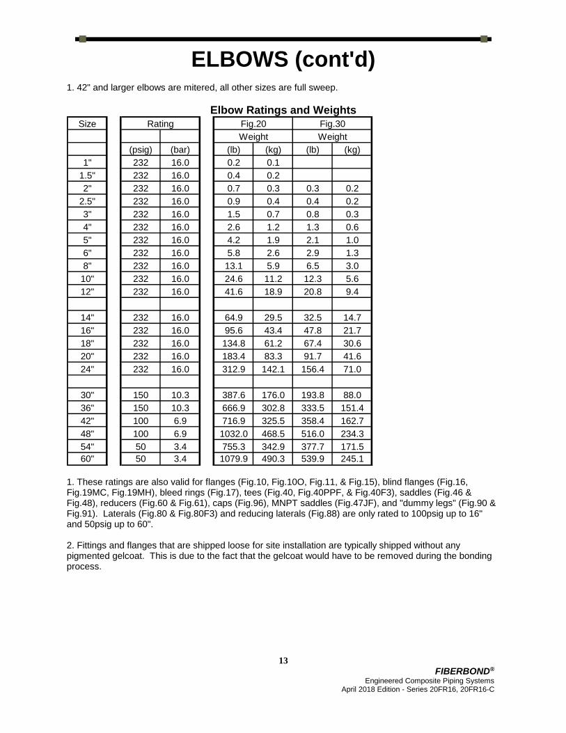
ELBOWS (cont'd) 1. 42" and larger elbows are mitered, all other sizes are full sweep.
Elbow Ratings and Weights
Size Rating Fig.20 Fig.30
Weight Weight
(psig) (bar) (lb) (kg) (lb) (kg)
1" 232 16.0 0.2 0.1
1.5" 232 16.0 0.4 0.2
2" 232 16.0 0.7 0.3 0.3 0.2
2.5" 232 16.0 0.9 0.4 0.4 0.2
3" 232 16.0 1.5 0.7 0.8 0.3
4" 232 16.0 2.6 1.2 1.3 0.6
5" 232 16.0 4.2 1.9 2.1 1.0
6" 232 16.0 5.8 2.6 2.9 1.3
8" 232 16.0 13.1 5.9 6.5 3.0
10" 232 16.0 24.6 11.2 12.3 5.6
12" 232 16.0 41.6 18.9 20.8 9.4
14" 232 16.0 64.9 29.5 32.5 14.7
16" 232 16.0 95.6 43.4 47.8 21.7
18" 232 16.0 134.8 61.2 67.4 30.6
20" 232 16.0 183.4 83.3 91.7 41.6
24" 232 16.0 312.9 142.1 156.4 71.0
30" 150 10.3 387.6 176.0 193.8 88.0
36" 150 10.3 666.9 302.8 333.5 151.4
42" 100 6.9 716.9 325.5 358.4 162.7
48" 100 6.9 1032.0 468.5 516.0 234.3
54" 50 3.4 755.3 342.9 377.7 171.5
60" 50 3.4 1079.9 490.3 539.9 245.1
1. These ratings are also valid for flanges (Fig.10, Fig.10O, Fig.11, & Fig.15), blind flanges (Fig.16, Fig.19MC, Fig.19MH), bleed rings (Fig.17), tees (Fig.40, Fig.40PPF, & Fig.40F3), saddles (Fig.46 & Fig.48), reducers (Fig.60 & Fig.61), caps (Fig.96), MNPT saddles (Fig.47JF), and "dummy legs" (Fig.90 & Fig.91). Laterals (Fig.80 & Fig.80F3) and reducing laterals (Fig.88) are only rated to 100psig up to 16" and 50psig up to 60". 2. Fittings and flanges that are shipped loose for site installation are typically shipped without any pigmented gelcoat. This is due to the fact that the gelcoat would have to be removed during the bonding process.

14
FIBERBOND® Engineered Composite Piping Systems
April 2018 Edition - Series 20FR16, 20FR16-C
REDUCERS
Size E E+L FOD FROD O
(in.) (mm) (in.) (mm) (in.) (mm) (in.) (mm) (in.) (mm)
1.5"x1" 1.25" 32 7.25" 184 2.00" 51 1.50" 38 0.25" 6
2"x1.5" 1.25" 32 7.25" 184 2.62" 67 2.00" 51 0.31" 8
2"x1" 2.50" 64 8.50" 216 2.62" 67 1.50" 38 0.56" 14
2.5"x2" 1.25" 32 7.25" 184 3.00" 76 2.62" 67 0.19" 5
3"x2.5" 1.25" 32 7.25" 184 3.50" 89 3.00" 76 0.25" 6
3"x2" 2.50" 64 8.50" 216 3.50" 89 2.62" 67 0.44" 11
3"x1.5" 3.75" 95 9.75" 248 3.50" 89 2.00" 51 0.75" 19
3"x1" 5" 127 11" 279 3.50" 89 1.50" 38 1.00" 25
4"x3" 2.50" 64 8.50" 216 4.50" 114 3.50" 89 0.50" 13
4"x2.5" 3.75" 95 9.75" 248 4.50" 114 3.00" 76 0.75" 19
4"x2" 5" 127 11" 279 4.50" 114 2.62" 67 0.94" 24
4"x1.5" 6.25" 159 12.25" 311 4.50" 114 2.00" 51 1.25" 32
4"x1" 7.50" 191 13.50" 343 4.50" 114 1.50" 38 1.50" 38
5"x4" 2.50" 64 8.50" 216 5.50" 140 4.50" 114 0.50" 13
6"x5" 2.50" 64 8.50" 216 6.54" 166 5.50" 140 0.52" 13
6"x4" 5" 127 11" 279 6.54" 166 4.50" 114 1.02" 26
6"x3" 7.50" 191 13.50" 343 6.54" 166 3.50" 89 1.52" 39
6"x2.5" 8.75" 222 14.75" 375 6.54" 166 3.00" 76 1.77" 45
6"x2" 10" 254 16" 406 6.54" 166 2.62" 67 1.96" 50
8"x6" 5" 127 13" 330 8.70" 221 6.54" 166 1.08" 27
8"x5" 7.50" 191 13.50" 343 8.70" 221 5.50" 140 1.60" 41
8"x4" 10" 254 16" 406 8.70" 221 4.50" 114 2.10" 53
8"x3" 12.50" 318 18.50" 470 8.70" 221 3.50" 89 2.60" 66

15
FIBERBOND® Engineered Composite Piping Systems
April 2018 Edition - Series 20FR16, 20FR16-C
REDUCERS (cont'd)
1. Offset dimension for eccentric reducers is 0.5” x (FOD - FROD). 2. Reducers may be available in other sizes than those shown above. Min. E+L dimensions are also available. 3. The FLOD and FLOD2 dimensions match ASME B16.5 150# and B16.1 125# O.D.s.
Reducer Dimensions (cont'd) Size E E+L FOD FROD O
(in.) (mm) (in.) (mm) (in.) (mm) (in.) (mm) (in.) (mm)
10"x8" 5" 127 15" 381 10.86" 276 8.70" 221 1.08" 27
10"x6" 10" 254 18" 457 10.86" 276 6.54" 166 2.16" 55
10"x5" 12.50" 318 18.50" 470 10.86" 276 5.50" 140 2.68" 68
10"x4" 15" 381 21" 533 10.86" 276 4.50" 114 3.18" 81
12"x10" 5" 127 17" 432 13.02" 331 10.86" 276 1.08" 27
12"x8" 10" 254 20" 508 13.02" 331 8.70" 221 2.16" 55
12"x6" 15" 381 23" 584 13.02" 331 6.54" 166 3.24" 82
14"x12" 5" 127 19" 483 15.45" 392 13.02" 331 1.22" 31
14"x10" 10" 254 22" 559 15.45" 392 10.86" 276 2.30" 58
14"x8" 15" 381 25" 635 15.45" 392 8.70" 221 3.38" 86
16"x14" 5" 127 20" 508 17.61" 447 15.45" 392 1.08" 27
16"x12" 10" 254 24" 610 17.61" 447 13.02" 331 2.30" 58
16"x10" 15" 381 27" 686 17.61" 447 10.86" 276 3.38" 86
18"x16" 5" 127 22" 559 19.77" 502 17.61" 447 1.08" 27
18"x14" 10" 254 25" 635 19.77" 502 15.45" 392 2.16" 55
18"x12" 15" 381 29" 737 19.77" 502 13.02" 331 3.38" 86
20"x18" 5" 127 23" 584 21.93" 557 19.77" 502 1.08" 27
20"x16" 10" 254 27" 686 21.93" 557 17.61" 447 2.16" 55
20"x14" 15" 381 30" 762 21.93" 557 15.45" 392 3.24" 82
24"x20" 10" 254 30" 762 26.25" 667 21.93" 557 2.16" 55
24"x18" 15" 381 33" 838 26.25" 667 19.77" 502 3.24" 82
30"x24" 15" 381 39" 991 31.85" 809 26.25" 667 2.80" 71
36"x30" 15" 381 39" 991 38.15" 969 31.85" 809 3.15" 80
42"x36" 15" 381 39" 991 43.73" 1111 38.15" 969 2.79" 71
48"x42" 15" 381 39" 991 49.93" 1268 43.73" 1111 3.10" 79
54"x48" 15" 381 39" 991 55.21" 1402 49.93" 1268 2.64" 67
60"x54" 30" 762 54" 1372 61.31" 1557 55.21" 1402 3.05" 77

16
FIBERBOND® Engineered Composite Piping Systems
April 2018 Edition - Series 20FR16, 20FR16-C
REDUCERS (cont'd)
Reducer Weights Size Fig.60, 61 Fig.60FF, 61FF Size Fig.60, 61 Fig.60FF, 61FF
(lb) (kg) (lb) (kg) (lb) (kg) (lb) (kg)
1.5"x1" 0.1 0.0 2.5 1.1 12"x10" 5.5 2.5 52.4 23.8
2"x1.5" 0.3 0.1 3.3 1.5 12"x8" 11.0 5.0 47.8 21.7
2"x1" 0.3 0.1 3.1 1.4 12"x6" 16.5 7.5 63.4 28.8
2.5"x2" 0.2 0.1 4.2 1.9
14"x12" 7.4 3.4 71.5 32.5
3"x2.5" 0.4 0.2 5.5 2.5 14"x10" 14.8 6.7 67.7 30.7
3"x2" 0.4 0.2 4.8 2.2 14"x8" 22.1 10.1 64.9 29.5
3"x1.5" 0.8 0.4 4.7 2.1
3"x1" 0.8 0.4 4.4 2.0 16"x14" 9.5 4.3 98.4 44.7
16"x12" 19.0 8.6 94.5 42.9
4"x3" 0.5 0.2 7.5 3.4 16"x10" 28.5 13.0 92.8 42.1
4"x2.5" 1.0 0.5 7.5 3.4
4"x2" 1.0 0.5 6.9 3.1 18"x16" 11.9 5.4 126.2 57.3
4"x1.5" 1.6 0.7 6.9 3.1 18"x14" 23.8 10.8 119.6 54.3
4"x1" 1.6 0.7 6.6 3.0 18"x12" 47.7 21.6 118.2 53.6
5"x4" 0.6 0.3 10.1 4.6 20"x18" 14.6 6.6 155.2 70.4
20"x16" 29.2 13.3 157.1 71.3
6"x5" 0.8 0.4 13.0 5.9 20"x14" 43.8 19.9 153.2 69.5
6"x4" 1.5 0.7 12.7 5.8
6"x3" 2.3 1.1 11.7 5.3 24"x20" 41.5 18.8 231.1 104.9
6"x2.5" 3.1 1.4 12.0 5.4 24"x18" 62.2 28.3 231.9 105.3
6"x2" 3.1 1.4 11.3 5.1
30"x24" 61.7 28.0 332.5 150.9
8"x6" 2.6 1.2 20.8 9.4 36"x30" 88.5 40.2 490.1 222.5
8"x5" 3.9 1.8 19.3 8.8 42"x36" 81.5 37.0 637.2 289.3
8"x4" 5.2 2.4 19.6 8.9 48"x42" 102.7 46.6 793.5 360.2
8"x3" 6.5 3.0 19.1 8.7 54"x48" 66.8 30.3 909.4 412.9
60"x54" 85.9 39.0 991.8 450.3
10"x8" 3.9 1.8 33.8 15.4
10"x6" 7.8 3.6 32.2 14.6
10"x5" 9.8 4.4 31.4 14.3
10"x4" 11.8 5.3 33.8 15.3

17
FIBERBOND® Engineered Composite Piping Systems
April 2018 Edition - Series 20FR16, 20FR16-C
EQUAL SIZE & REDUCING TEES
Size Fig.40
G FOD Weight
(in.) (mm) (lb) (kg) (lb) (kg)
1" 5" 127 1.50" 38 1.8 0.8
1.5" 5.5" 140 2.00" 51 2.7 1.2
2" 6" 152 2.62" 67 2.0 0.9
2.5" 6.5" 165 3.00" 76 2.4 1.1
3" 7" 178 3.50" 89 3.4 1.5
4" 8" 203 4.50" 114 5.0 2.3
5" 9" 229 5.50" 140 7.2 3.3
6" 10" 254 6.54" 166 9.3 4.2
8" 12" 305 8.70" 221 18.7 8.5
10" 14" 356 10.86" 276 32.9 15.0
12" 16" 406 13.02" 331 53.0 24.0
14" 18" 457 15.45" 392 79.7 36.2
16" 20" 508 17.61" 447 114.1 51.8
18" 21" 533 19.77" 502 295.5 134.2
20" 22" 559 1.68" 43 379.1 172.1
24" 24" 610 26.25" 667 611.3 277.5
30" 30" 762 31.85" 809 653.8 296.8
36" 33" 838 38.15" 969 1053.4 478.3
42" 36" 914 43.73" 1111 1002.4 455.1
48" 45" 1143 49.93" 1268 1497.5 679.9
54" 54" 1372 55.21" 1402 960.8 436.2
60" 54" 1372 61.31" 1557 1256.1 570.3

18
FIBERBOND® Engineered Composite Piping Systems
April 2018 Edition - Series 20FR16, 20FR16-C
EQUAL SIZE & REDUCING TEES (cont'd)
Size Fig.43
G FOD FROD Weight
(in.) (mm) (lb) (kg) (lb) (kg) (lb) (kg)
8"x6" 12" 305 8.70" 221 6.54" 166 16.6 7.5
10"x8" 14" 356 10.86" 276 8.70" 221 29.9 13.6
10"x6" 14" 356 10.86" 276 6.54" 166 26.9 12.2
12"x10" 16" 406 13.02" 331 10.86" 276 48.7 22.1
12"x8" 16" 406 13.02" 331 8.70" 221 44.5 20.2
14"x12" 18" 457 15.45" 392 13.02" 331 74.2 33.7
14"x10" 18" 457 15.45" 392 10.86" 276 68.4 31.0
16"x14" 20" 508 17.61" 447 15.45" 392 107.1 48.6
16"x12" 20" 508 17.61" 447 13.02" 331 99.6 45.2
16"x10" 20" 508 17.61" 447 10.86" 276 93.1 42.3
18"x16" 21" 533 19.77" 502 17.61" 447 270.4 122.8
18"x14" 21" 533 19.77" 502 15.45" 392 246.7 112.0
18"x12" 21" 533 19.77" 502 13.02" 331 230.8 104.8
20"x18" 22" 559 21.93" 557 19.77" 502 351.3 159.5
20"x16" 22" 559 21.93" 557 17.61" 447 326.1 148.1
20"x14" 22" 559 21.93" 557 15.45" 392 302.5 137.3
24"x20" 24" 610 26.25" 667 21.93" 557 533.9 242.4
24"x18" 24" 610 26.25" 667 19.77" 502 506.0 229.7
24"x16" 24" 610 26.25" 667 17.61" 447 480.9 218.3
30"x24" 30" 762 31.85" 809 26.25" 667 640.1 290.6
36"x30" 33" 838 38.15" 969 31.85" 809 920.4 417.9
42"x36" 36" 914 43.73" 1111 38.15" 969 1019.5 462.8
48"x42" 45" 1143 49.93" 1268 43.73" 1111 1332.5 605.0
54"x48" 54" 1372 55.21" 1402 49.93" 1268 1139.9 517.5
60"x54" 54" 1372 61.31" 1557 55.21" 1402 1157.9 525.7
60"x48" 54" 1372 61.31" 1557 49.93" 1268 1336.8 606.9
1. Some tees and reducing tees are offer as a molded fitting and others as a fabricated fitting. Temperature and pressure ratings are the same amongst the two construction methods.
2. A Fig.48 plain end olet may be more economical than a reducing tee. 3. For sizes not listed above, a Fig.48 plain end olet may be used.

19
FIBERBOND® Engineered Composite Piping Systems
April 2018 Edition - Series 20FR16, 20FR16-C
OLETS, PLAIN AND FLANGED
A2
6" 7" 8" 10" 12" 14" 16" 18"
Branch Diameter
1",1.5",2" 2.5", 3" 4" 5", 6" 8" 10" 12" 14"
LS
6" 1"
6" 1.5" 7"
6" 2" 7"
6" 2.5" 7.5"
7" 3" 7.5" 7.5"
8" 4" 8" 8"
10" 5" 9" 9" 10"
10" 6" 9" 9" 10" 13"
12" 8" 10" 10" 11" 14"
14" 10" 11" 11" 12" 15" 18"
16" 12" 12" 12" 13" 16" 19"
18" 14" 13" 13" 14" 17" 20"
20" 16" 14" 14" 15" 18" 21"
21" 18" 15" 15" 16" 19" 22"
22" 20" 16" 16" 17" 20" 23"
24" 24" 18" 18" 19" 22" 25"
30" 30" 21" 21" 22" 25" 28"
33" 36" 24" 24" 25" 28" 31"
36" 42" 27" 27" 28" 31" 34"
45" 48" 30" 30" 31" 34" 37"
54" 54" 33" 33" 34" 37" 40"
54" 60" 36" 36" 37" 40" 43"
H
He
ad
er
Dia
me
ter
1. The 'H' dimension is based on header size. The 'A2' dimension is based on branch size. The 'LS' dimension is based on both header and branch size; e.g. 3” on 6” Fig. 46 has LS = 9”, A2 = 7” 2. An olet fitting includes only the branch components. Unless purchased as part of a pre-fabricated (pre-assembled) system, it does require some assembly and bonding work.

20
FIBERBOND® Engineered Composite Piping Systems
April 2018 Edition - Series 20FR16, 20FR16-C
OLETS, PLAIN AND FLANGED (cont'd)
Flanged End Olet Dimensions Size LS A2 LTHK FLOD Weight
(in.) (mm) (in.) (mm) (in.) (mm) (in.) (mm) (lb) (kg)
1.5"x1" 7.00" 178 6.00" 152 0.50" 13 4.25" 108 2.0 0.9
2"x1.5" 7.00" 178 6.00" 152 0.52" 13 5.00" 127 2.5 1.1
2"x1" 7.00" 178 6.00" 152 0.50" 13 4.25" 108 2.0 0.9
2.5"x2" 7.50" 191 6.00" 152 0.64" 16 6.00" 152 3.3 1.5
3"x2.5" 7.50" 191 7.00" 178 0.72" 18 7.00" 178 4.3 2.0
3"x2" 7.50" 191 6.00" 152 0.64" 16 6.00" 152 3.3 1.5
3"x1.5" 7.50" 191 6.00" 152 0.52" 13 5.00" 127 2.5 1.1
3"x1" 7.50" 191 6.00" 152 0.50" 13 4.25" 108 2.0 0.9
4"x3" 8.00" 203 7.00" 178 0.77" 20 7.50" 191 5.0 2.3
4"x2.5" 8.00" 203 7.00" 178 0.72" 18 7.00" 178 4.3 2.0
4"x2" 8.00" 203 6.00" 152 0.64" 16 6.00" 152 3.3 1.5
4"x1.5" 8.00" 203 6.00" 152 0.52" 13 5.00" 127 2.5 1.1
4"x1" 8.00" 203 6.00" 152 0.50" 13 4.25" 108 2.0 0.9
5"x4" 10.00" 254 8.00" 203 1.01" 26 9.00" 229 7.6 3.5
6"x5" 13.00" 330 10.00" 254 1.10" 28 10.00" 254 12.0 5.4
6"x4" 10.00" 254 8.00" 203 1.01" 26 9.00" 229 7.6 3.5
6"x3" 9.00" 229 7.00" 178 0.77" 20 7.50" 191 5.0 2.3
6"x2.5" 9.00" 229 7.00" 178 0.72" 18 7.00" 178 4.3 2.0
6"x2" 9.00" 229 6.00" 152 0.64" 16 6.00" 152 3.3 1.5
6"x1.5" 9.00" 229 6.00" 152 0.52" 13 5.00" 127 2.5 1.1
6"x1" 9.00" 229 6.00" 152 0.50" 13 4.25" 108 2.0 0.9
8"x6" 14.00" 356 10.00" 254 1.19" 30 11.00" 279 16.3 7.4
8"x5" 14.00" 356 10.00" 254 1.10" 28 10.00" 254 12.0 5.4
8"x4" 11.00" 279 8.00" 203 1.01" 26 9.00" 229 7.6 3.5
8"x3" 10.00" 254 7.00" 178 0.77" 20 7.50" 191 5.0 2.3
8"x2.5" 10.00" 254 7.00" 178 0.72" 18 7.00" 178 4.3 2.0
8"x2" 10.00" 254 6.00" 152 0.64" 16 6.00" 152 3.3 1.5
8"x1.5" 10.00" 254 6.00" 152 0.52" 13 5.00" 127 2.5 1.1
8"x1" 10.00" 254 6.00" 152 0.50" 13 4.25" 108 2.0 0.9
10"x8" 18.00" 457 12.00" 305 1.36" 35 13.50" 343 30.4 13.8
10"x6" 15.00" 381 10.00" 254 1.19" 30 11.00" 279 16.3 7.4
10"x5" 15.00" 381 10.00" 254 1.10" 28 10.00" 254 12.0 5.4
10"x4" 12.00" 305 8.00" 203 1.01" 26 9.00" 229 7.6 3.5
10"x3" 11.00" 279 7.00" 178 0.77" 20 7.50" 191 5.0 2.3
10"x2.5" 11.00" 279 7.00" 178 0.72" 18 7.00" 178 4.3 2.0
10"x2" 11.00" 279 6.00" 152 0.64" 16 6.00" 152 3.3 1.5
10"x1.5" 11.00" 279 6.00" 152 0.52" 13 5.00" 127 2.5 1.1
10"x1" 11.00" 279 6.00" 152 0.50" 13 4.25" 108 2.0 0.9

21
FIBERBOND® Engineered Composite Piping Systems
April 2018 Edition - Series 20FR16, 20FR16-C
OLETS, PLAIN AND FLANGED (cont'd)
Flanged End Olet Dimensions (cont'd) Size LS A2 LTHK FLOD Weight
(in.) (mm) (in.) (mm) (in.) (mm) (in.) (mm) (lb) (kg)
12"x10"
12"x8" 19.00" 483 12.00" 305 1.36" 35 13.50" 343 30.4 13.8
12"x6" 16.00" 406 10.00" 254 1.19" 30 11.00" 279 16.3 7.4
12"x5" 16.00" 406 10.00" 254 1.10" 28 10.00" 254 12.0 5.4
12"x4" 13.00" 330 8.00" 203 1.01" 26 9.00" 229 7.6 3.5
12"x3" 12.00" 305 7.00" 178 0.77" 20 7.50" 191 5.0 2.3
12"x2.5" 12.00" 305 7.00" 178 0.72" 18 7.00" 178 4.3 2.0
12"x2" 12.00" 305 6.00" 152 0.64" 16 6.00" 152 3.3 1.5
12"x1.5" 12.00" 305 6.00" 152 0.52" 13 5.00" 127 2.5 1.1
12"x1" 12.00" 305 6.00" 152 0.50" 13 4.25" 108 2.0 0.9
14"x12"
14"x10"
14"x8" 20.00" 508 12.00" 305 1.36" 35 13.50" 343 30.4 13.8
14"x6" 17.00" 432 10.00" 254 1.19" 30 11.00" 279 16.3 7.4
14"x5" 17.00" 432 10.00" 254 1.10" 28 10.00" 254 12.0 5.4
14"x4" 14.00" 356 8.00" 203 1.01" 26 9.00" 229 7.6 3.5
14"x3" 13.00" 330 7.00" 178 0.77" 20 7.50" 191 5.0 2.3
14"x2.5" 13.00" 330 7.00" 178 0.72" 18 7.00" 178 4.3 2.0
14"x2" 13.00" 330 6.00" 152 0.64" 16 6.00" 152 3.3 1.5
14"x1.5" 13.00" 330 6.00" 152 0.52" 13 5.00" 127 2.5 1.1
14"x1" 13.00" 330 6.00" 152 0.50" 13 4.25" 108 2.0 0.9
16"x14"
16"x12"
16"x10"
16"x8" 21.00" 533 12.00" 305 1.36" 35 13.50" 343 30.4 13.8
16"x6" 18.00" 457 10.00" 254 1.19" 30 11.00" 279 16.3 7.4
16"x5" 18.00" 457 10.00" 254 1.10" 28 10.00" 254 12.0 5.4
16"x4" 15.00" 381 8.00" 203 1.01" 26 9.00" 229 7.6 3.5
16"x3" 14.00" 356 7.00" 178 0.77" 20 7.50" 191 5.0 2.3
16"x2.5" 14.00" 356 7.00" 178 0.72" 18 7.00" 178 4.3 2.0
16"x2" 14.00" 356 6.00" 152 0.64" 16 6.00" 152 3.3 1.5
16"x1.5" 14.00" 356 6.00" 152 0.52" 13 5.00" 127 2.5 1.1
16"x1" 14.00" 356 6.00" 152 0.50" 13 4.25" 108 2.0 0.9
18"x16"
18"x14"
18"x12"

22
FIBERBOND® Engineered Composite Piping Systems
April 2018 Edition - Series 20FR16, 20FR16-C
OLETS, PLAIN AND FLANGED (cont'd)
Flanged End Olet Dimensions (cont'd) Size LS A2 LTHK FLOD Weight
(in.) (mm) (in.) (mm) (in.) (mm) (in.) (mm) (lb) (kg)
18"x10"
18"x8" 22.00" 559 12.00" 305 1.36" 35 13.50" 343 30.4 13.8
18"x6" 19.00" 483 10.00" 254 1.19" 30 11.00" 279 16.3 7.4
18"x5" 19.00" 483 10.00" 254 1.10" 28 10.00" 254 12.0 5.4
18"x4" 16.00" 406 8.00" 203 1.01" 26 9.00" 229 7.6 3.5
18"x3" 15.00" 381 7.00" 178 0.77" 20 7.50" 191 5.0 2.3
18"x2.5" 15.00" 381 7.00" 178 0.72" 18 7.00" 178 4.3 2.0
18"x2" 15.00" 381 6.00" 152 0.64" 16 6.00" 152 3.3 1.5
18"x1.5" 15.00" 381 6.00" 152 0.52" 13 5.00" 127 2.5 1.1
18"x1" 15.00" 381 6.00" 152 0.50" 13 4.25" 108 2.0 0.9
20"x18"
20"x16"
20"x14"
20"x12"
20"x10"
20"x8" 23.00" 584 12.00" 305 1.36" 35 13.50" 343 30.4 13.8
20"x6" 20.00" 508 10.00" 254 1.19" 30 11.00" 279 16.3 7.4
20"x5" 20.00" 508 10.00" 254 1.10" 28 10.00" 254 12.0 5.4
20"x4" 17.00" 432 8.00" 203 1.01" 26 9.00" 229 7.6 3.5
20"x3" 16.00" 406 7.00" 178 0.77" 20 7.50" 191 5.0 2.3
20"x2.5" 16.00" 406 7.00" 178 0.72" 18 7.00" 178 4.3 2.0
20"x2" 16.00" 406 6.00" 152 0.64" 16 6.00" 152 3.3 1.5
20"x1.5" 16.00" 406 6.00" 152 0.52" 13 5.00" 127 2.5 1.1
20"x1" 16.00" 406 6.00" 152 0.50" 13 4.25" 108 2.0 0.9
24"x20"
24"x18"
24"x16"
24"x14"
24"x12"
24"x10"
24"x8" 25.00" 635 12.00" 305 1.36" 35 13.50" 343 30.4 13.8
24"x6" 22.00" 559 10.00" 254 1.19" 30 11.00" 279 16.3 7.4
24"x5" 22.00" 559 10.00" 254 1.10" 28 10.00" 254 12.0 5.4
24"x4" 19.00" 483 8.00" 203 1.01" 26 9.00" 229 7.6 3.5
24"x3" 18.00" 457 7.00" 178 0.77" 20 7.50" 191 5.0 2.3
24"x2.5" 18.00" 457 7.00" 178 0.72" 18 7.00" 178 4.3 2.0
24"x2" 18.00" 457 6.00" 152 0.64" 16 6.00" 152 3.3 1.5
24"x1.5" 18.00" 457 6.00" 152 0.52" 13 5.00" 127 2.5 1.1
24"x1" 18.00" 457 6.00" 152 0.50" 13 4.25" 108 2.0 0.9

23
FIBERBOND® Engineered Composite Piping Systems
April 2018 Edition - Series 20FR16, 20FR16-C
OLETS, PLAIN AND FLANGED (cont'd)
Flanged End Olet Dimensions (cont'd) Size LS A2 LTHK FLOD Weight
(in.) (mm) (in.) (mm) (in.) (mm) (in.) (mm) (lb) (kg)
30"x24"
30"x20"
30"x18"
30"x16"
30"x14"
30"x12"
30"x10"
30"x8" 28.00" 711 12.00" 305 1.36" 35 13.50" 343 30.4 13.8
30"x6" 25.00" 635 10.00" 254 1.19" 30 11.00" 279 16.3 7.4
30"x5" 25.00" 635 10.00" 254 1.10" 28 10.00" 254 12.0 5.4
30"x4" 22.00" 559 8.00" 203 1.01" 26 9.00" 229 7.6 3.5
30"x3" 21.00" 533 7.00" 178 0.77" 20 7.50" 191 5.0 2.3
30"x2.5" 21.00" 533 7.00" 178 0.72" 18 7.00" 178 4.3 2.0
30"x2" 21.00" 533 6.00" 152 0.64" 16 6.00" 152 3.3 1.5
30"x1.5" 21.00" 533 6.00" 152 0.52" 13 5.00" 127 2.5 1.1
30"x1" 21.00" 533 6.00" 152 0.50" 13 4.25" 108 2.0 0.9
36"x30"
36"x24"
36"x20"
36"x18"
36"x16"
36"x14"
36"x12"
36"x10"
36"x8" 31.00" 787 12.00" 305 1.36" 35 13.50" 343 30.4 13.8
36"x6" 28.00" 711 10.00" 254 1.19" 30 11.00" 279 16.3 7.4
36"x5" 28.00" 711 10.00" 254 1.10" 28 10.00" 254 12.0 5.4
36"x4" 25.00" 635 8.00" 203 1.01" 26 9.00" 229 7.6 3.5
36"x3" 24.00" 610 7.00" 178 0.77" 20 7.50" 191 5.0 2.3
36"x2.5" 24.00" 610 7.00" 178 0.72" 18 7.00" 178 4.3 2.0
36"x2" 24.00" 610 6.00" 152 0.64" 16 6.00" 152 3.3 1.5
36"x1.5" 24.00" 610 6.00" 152 0.52" 13 5.00" 127 2.5 1.1
36"x1" 24.00" 610 6.00" 152 0.50" 13 4.25" 108 2.0 0.9

24
FIBERBOND® Engineered Composite Piping Systems
April 2018 Edition - Series 20FR16, 20FR16-C
OLETS, PLAIN AND FLANGED (cont'd)
Flanged End Olet Dimensions (cont'd) Size LS A2 LTHK FLOD Weight
(in.) (mm) (in.) (mm) (in.) (mm) (in.) (mm) (lb) (kg)
42"x36"
42"x30"
42"x24"
42"x20"
42"x18"
42"x16"
42"x14"
42"x12"
42"x10"
42"x8" 34.00" 864 12.00" 305 1.36" 35 13.50" 343 30.4 13.8
42"x6" 31.00" 787 10.00" 254 1.19" 30 11.00" 279 16.3 7.4
42"x5" 31.00" 787 10.00" 254 1.10" 28 10.00" 254 12.0 5.4
42"x4" 28.00" 711 8.00" 203 1.01" 26 9.00" 229 7.6 3.5
42"x3" 27.00" 686 7.00" 178 0.77" 20 7.50" 191 5.0 2.3
42"x2.5" 27.00" 686 7.00" 178 0.72" 18 7.00" 178 4.3 2.0
42"x2" 27.00" 686 6.00" 152 0.64" 16 6.00" 152 3.3 1.5
42"x1.5" 27.00" 686 6.00" 152 0.52" 13 5.00" 127 2.5 1.1
42"x1" 27.00" 686 6.00" 152 0.50" 13 4.25" 108 2.0 0.9
48"x42"
48"x36"
48"x30"
48"x24"
48"x20"
48"x18"
48"x16"
48"x14"
48"x12"
48"x10"
48"x8" 37.00" 940 12.00" 305 1.36" 35 13.50" 343 30.4 13.8
48"x6" 34.00" 864 10.00" 254 1.19" 30 11.00" 279 16.3 7.4
48"x5" 34.00" 864 10.00" 254 1.10" 28 10.00" 254 12.0 5.4
48"x4" 31.00" 787 8.00" 203 1.01" 26 9.00" 229 7.6 3.5
48"x3" 30.00" 762 7.00" 178 0.77" 20 7.50" 191 5.0 2.3
48"x2.5" 30.00" 762 7.00" 178 0.72" 18 7.00" 178 4.3 2.0
48"x2" 30.00" 762 6.00" 152 0.64" 16 6.00" 152 3.3 1.5
48"x1.5" 30.00" 762 6.00" 152 0.52" 13 5.00" 127 2.5 1.1
48"x1" 30.00" 762 6.00" 152 0.50" 13 4.25" 108 2.0 0.9

25
FIBERBOND® Engineered Composite Piping Systems
April 2018 Edition - Series 20FR16, 20FR16-C
OLETS, PLAIN AND FLANGED (cont'd)
Flanged End Olet Dimensions (cont'd) Size LS A2 LTHK FLOD Weight
(in.) (mm) (in.) (mm) (in.) (mm) (in.) (mm) (lb) (kg)
54"x48"
54"x42"
54"x36"
54"x30"
54"x24"
54"x20"
54"x18"
54"x16"
54"x14"
54"x12"
54"x10"
54"x8" 40.00" 1016 12.00" 305 1.36" 35 13.50" 343 30.4 13.8
54"x6" 37.00" 940 10.00" 254 1.19" 30 11.00" 279 16.3 7.4
54"x5" 37.00" 940 10.00" 254 1.10" 28 10.00" 254 12.0 5.4
54"x4" 34.00" 864 8.00" 203 1.01" 26 9.00" 229 7.6 3.5
54"x3" 33.00" 838 7.00" 178 0.77" 20 7.50" 191 5.0 2.3
54"x2.5" 33.00" 838 7.00" 178 0.72" 18 7.00" 178 4.3 2.0
54"x2" 33.00" 838 6.00" 152 0.64" 16 6.00" 152 3.3 1.5
54"x1.5" 33.00" 838 6.00" 152 0.52" 13 5.00" 127 2.5 1.1
54"x1" 33.00" 838 6.00" 152 0.50" 13 4.25" 108 2.0 0.9
60"x54"
60"x48"
60"x42"
60"x36"
60"x30"
60"x24"
60"x20"
60"x18"
60"x16"
60"x14"
60"x12"
60"x10"
60"x8" 43.00" 1092 12.00" 305 1.36" 35 13.50" 343 30.4 13.8
60"x6" 40.00" 1016 10.00" 254 1.19" 30 11.00" 279 16.3 7.4
60"x5" 40.00" 1016 10.00" 254 1.10" 28 10.00" 254 12.0 5.4
60"x4" 37.00" 940 8.00" 203 1.01" 26 9.00" 229 7.6 3.5
60"x3" 36.00" 914 7.00" 178 0.77" 20 7.50" 191 5.0 2.3
60"x2.5" 36.00" 914 7.00" 178 0.72" 18 7.00" 178 4.3 2.0
60"x2" 36.00" 914 6.00" 152 0.64" 16 6.00" 152 3.3 1.5
60"x1.5" 36.00" 914 6.00" 152 0.52" 13 5.00" 127 2.5 1.1
60"x1" 36.00" 914 6.00" 152 0.50" 13 4.25" 108 2.0 0.9

26
FIBERBOND® Engineered Composite Piping Systems
April 2018 Edition - Series 20FR16, 20FR16-C
OLETS, PLAIN AND FLANGED (cont'd)
Plain End Olet Dimensions Size H A2 POD PBOD Weight
(in.) (mm) (in.) (mm) (in.) (mm) (in.) (mm) (lb) (kg)
1.5"x1" 6.00" 152 6.00" 152 2.00" 51 1.50" 38 0.9 0.4
2"x1.5" 6.00" 152 6.00" 152 2.62" 67 2.00" 51 1.3 0.6
2"x1" 6.00" 152 6.00" 152 2.62" 67 1.50" 38 0.9 0.4
2.5"x2" 7.00" 178 6.00" 152 3.00" 76 2.62" 67 1.6 0.7
3"x2.5" 7.00" 178 7.00" 178 3.50" 89 3.00" 76 2.0 0.9
3"x2" 7.00" 178 6.00" 152 3.50" 89 2.62" 67 1.6 0.7
3"x1.5" 7.00" 178 6.00" 152 3.50" 89 2.00" 51 1.3 0.6
3"x1" 7.00" 178 6.00" 152 3.50" 89 1.50" 38 0.9 0.4
4"x3" 8.00" 203 7.00" 178 4.50" 114 3.50" 89 2.3 1.0
4"x2.5" 8.00" 203 7.00" 178 4.50" 114 3.00" 76 2.0 0.9
4"x2" 8.00" 203 6.00" 152 4.50" 114 2.62" 67 1.6 0.7
4"x1.5" 8.00" 203 6.00" 152 4.50" 114 2.00" 51 1.3 0.6
4"x1" 8.00" 203 6.00" 152 4.50" 114 1.50" 38 0.9 0.4
5"x4" 10.00" 254 8.00" 203 5.50" 140 4.50" 114 3.2 1.5
6"x5" 10.00" 254 10.00" 254 6.50" 165 5.50" 140 5.6 2.5
6"x4" 10.00" 254 8.00" 203 6.50" 165 4.50" 114 3.2 1.5
6"x3" 10.00" 254 7.00" 178 6.50" 165 3.50" 89 2.3 1.0
6"x2.5" 10.00" 254 7.00" 178 6.50" 165 3.00" 76 2.0 0.9
6"x2" 10.00" 254 6.00" 152 6.50" 165 2.62" 67 1.6 0.7
6"x1.5" 10.00" 254 6.00" 152 6.50" 165 2.00" 51 1.3 0.6
6"x1" 10.00" 254 6.00" 152 6.50" 165 1.50" 38 0.9 0.4
8"x6" 12.00" 305 10.00" 254 8.64" 219 6.50" 165 8.0 3.6
8"x5" 12.00" 305 10.00" 254 8.64" 219 5.50" 140 5.6 2.5
8"x4" 12.00" 305 8.00" 203 8.64" 219 4.50" 114 3.2 1.5
8"x3" 12.00" 305 7.00" 178 8.64" 219 3.50" 89 2.3 1.0
8"x2.5" 12.00" 305 7.00" 178 8.64" 219 3.00" 76 2.0 0.9
8"x2" 12.00" 305 6.00" 152 8.64" 219 2.62" 67 1.6 0.7
8"x1.5" 12.00" 305 6.00" 152 8.64" 219 2.00" 51 1.3 0.6
8"x1" 12.00" 305 6.00" 152 8.64" 219 1.50" 38 0.9 0.4
10"x8" 14.00" 356 12.00" 305 10.78" 274 8.64" 219 16.2 7.4
10"x6" 14.00" 356 10.00" 254 10.78" 274 6.50" 165 8.0 3.6
10"x5" 14.00" 356 10.00" 254 10.78" 274 5.50" 140 5.6 2.5
10"x4" 14.00" 356 8.00" 203 10.78" 274 4.50" 114 3.2 1.5
10"x3" 14.00" 356 7.00" 178 10.78" 274 3.50" 89 2.3 1.0
10"x2.5" 14.00" 356 7.00" 178 10.78" 274 3.00" 76 2.0 0.9
10"x2" 14.00" 356 6.00" 152 10.78" 274 2.62" 67 1.6 0.7
10"x1.5" 14.00" 356 6.00" 152 10.78" 274 2.00" 51 1.3 0.6
10"x1" 14.00" 356 6.00" 152 10.78" 274 1.50" 38 0.9 0.4

27
FIBERBOND® Engineered Composite Piping Systems
April 2018 Edition - Series 20FR16, 20FR16-C
OLETS, PLAIN AND FLANGED (cont'd)
Plain End Olet Dimensions (cont'd) Size H A2 POD PBOD Weight
(in.) (mm) (in.) (mm) (in.) (mm) (in.) (mm) (lb) (kg)
12"x10"
12"x8" 16.00" 406 12.00" 305 12.92" 328 8.64" 219 16.2 7.4
12"x6" 16.00" 406 10.00" 254 12.92" 328 6.50" 165 8.0 3.6
12"x5" 16.00" 406 10.00" 254 12.92" 328 5.50" 140 5.6 2.5
12"x4" 16.00" 406 8.00" 203 12.92" 328 4.50" 114 3.2 1.5
12"x3" 16.00" 406 7.00" 178 12.92" 328 3.50" 89 2.3 1.0
12"x2.5" 16.00" 406 7.00" 178 12.92" 328 3.00" 76 2.0 0.9
12"x2" 16.00" 406 6.00" 152 12.92" 328 2.62" 67 1.6 0.7
12"x1.5" 16.00" 406 6.00" 152 12.92" 328 2.00" 51 1.3 0.6
12"x1" 16.00" 406 6.00" 152 12.92" 328 1.50" 38 0.9 0.4
14"x12"
14"x10"
14"x8" 18.00" 457 12.00" 305 15.33" 389 8.64" 219 16.2 7.4
14"x6" 18.00" 457 10.00" 254 15.33" 389 6.50" 165 8.0 3.6
14"x5" 18.00" 457 10.00" 254 15.33" 389 5.50" 140 5.6 2.5
14"x4" 18.00" 457 8.00" 203 15.33" 389 4.50" 114 3.2 1.5
14"x3" 18.00" 457 7.00" 178 15.33" 389 3.50" 89 2.3 1.0
14"x2.5" 18.00" 457 7.00" 178 15.33" 389 3.00" 76 2.0 0.9
14"x2" 18.00" 457 6.00" 152 15.33" 389 2.62" 67 1.6 0.7
14"x1.5" 18.00" 457 6.00" 152 15.33" 389 2.00" 51 1.3 0.6
14"x1" 18.00" 457 6.00" 152 15.33" 389 1.50" 38 0.9 0.4
16"x14"
16"x12"
16"x10"
16"x8" 20.00" 508 12.00" 305 17.49" 444 8.64" 219 16.2 7.4
16"x6" 20.00" 508 10.00" 254 17.49" 444 6.50" 165 8.0 3.6
16"x5" 20.00" 508 10.00" 254 17.49" 444 5.50" 140 5.6 2.5
16"x4" 20.00" 508 8.00" 203 17.49" 444 4.50" 114 3.2 1.5
16"x3" 20.00" 508 7.00" 178 17.49" 444 3.50" 89 2.3 1.0
16"x2.5" 20.00" 508 7.00" 178 17.49" 444 3.00" 76 2.0 0.9
16"x2" 20.00" 508 6.00" 152 17.49" 444 2.62" 67 1.6 0.7
16"x1.5" 20.00" 508 6.00" 152 17.49" 444 2.00" 51 1.3 0.6
16"x1" 20.00" 508 6.00" 152 17.49" 444 1.50" 38 0.9 0.4
18"x16"
18"x14"
18"x12"

28
FIBERBOND® Engineered Composite Piping Systems
April 2018 Edition - Series 20FR16, 20FR16-C
OLETS, PLAIN AND FLANGED (cont'd)
Plain End Olet Dimensions (cont'd) Size H A2 POD PBOD Weight
(in.) (mm) (in.) (mm) (in.) (mm) (in.) (mm) (lb) (kg)
18"x10"
18"x8" 21.00" 533 12.00" 305 19.63" 499 8.64" 219 16.2 7.4
18"x6" 21.00" 533 10.00" 254 19.63" 499 6.50" 165 8.0 3.6
18"x5" 21.00" 533 10.00" 254 19.63" 499 5.50" 140 5.6 2.5
18"x4" 21.00" 533 8.00" 203 19.63" 499 4.50" 114 3.2 1.5
18"x3" 21.00" 533 7.00" 178 19.63" 499 3.50" 89 2.3 1.0
18"x2.5" 21.00" 533 7.00" 178 19.63" 499 3.00" 76 2.0 0.9
18"x2" 21.00" 533 6.00" 152 19.63" 499 2.62" 67 1.6 0.7
18"x1.5" 21.00" 533 6.00" 152 19.63" 499 2.00" 51 1.3 0.6
18"x1" 21.00" 533 6.00" 152 19.63" 499 1.50" 38 0.9 0.4
20"x18"
20"x16"
20"x14"
20"x12"
20"x10"
20"x8" 22.00" 559 12.00" 305 21.77" 553 8.64" 219 16.2 7.4
20"x6" 22.00" 559 10.00" 254 21.77" 553 6.50" 165 8.0 3.6
20"x5" 22.00" 559 10.00" 254 21.77" 553 5.50" 140 5.6 2.5
20"x4" 22.00" 559 8.00" 203 21.77" 553 4.50" 114 3.2 1.5
20"x3" 22.00" 559 7.00" 178 21.77" 553 3.50" 89 2.3 1.0
20"x2.5" 22.00" 559 7.00" 178 21.77" 553 3.00" 76 2.0 0.9
20"x2" 22.00" 559 6.00" 152 21.77" 553 2.62" 67 1.6 0.7
20"x1.5" 22.00" 559 6.00" 152 21.77" 553 2.00" 51 1.3 0.6
20"x1" 22.00" 559 6.00" 152 21.77" 553 1.50" 38 0.9 0.4
24"x20"
24"x18"
24"x16"
24"x14"
24"x12"
24"x10"
24"x8" 24.00" 610 12.00" 305 26.07" 662 8.64" 219 16.2 7.4
24"x6" 24.00" 610 10.00" 254 26.07" 662 6.50" 165 8.0 3.6
24"x5" 24.00" 610 10.00" 254 26.07" 662 5.50" 140 5.6 2.5
24"x4" 24.00" 610 8.00" 203 26.07" 662 4.50" 114 3.2 1.5
24"x3" 24.00" 610 7.00" 178 26.07" 662 3.50" 89 2.3 1.0
24"x2.5" 24.00" 610 7.00" 178 26.07" 662 3.00" 76 2.0 0.9
24"x2" 24.00" 610 6.00" 152 26.07" 662 2.62" 67 1.6 0.7
24"x1.5" 24.00" 610 6.00" 152 26.07" 662 2.00" 51 1.3 0.6
24"x1" 24.00" 610 6.00" 152 26.07" 662 1.50" 38 0.9 0.4

29
FIBERBOND® Engineered Composite Piping Systems
April 2018 Edition - Series 20FR16, 20FR16-C
OLETS, PLAIN AND FLANGED (cont'd)
Plain End Olet Dimensions (cont'd) Size H A2 POD PBOD Weight
(in.) (mm) (in.) (mm) (in.) (mm) (in.) (mm) (lb) (kg)
30"x24"
30"x20"
30"x18"
30"x16"
30"x14"
30"x12"
30"x10"
30"x8" 30.00" 762 12.00" 305 31.71" 805 8.64" 219 16.2 7.4
30"x6" 30.00" 762 10.00" 254 31.71" 805 6.50" 165 8.0 3.6
30"x5" 30.00" 762 10.00" 254 31.71" 805 5.50" 140 5.6 2.5
30"x4" 30.00" 762 8.00" 203 31.71" 805 4.50" 114 3.2 1.5
30"x3" 30.00" 762 7.00" 178 31.71" 805 3.50" 89 2.3 1.0
30"x2.5" 30.00" 762 7.00" 178 31.71" 805 3.00" 76 2.0 0.9
30"x2" 30.00" 762 6.00" 152 31.71" 805 2.62" 67 1.6 0.7
30"x1.5" 30.00" 762 6.00" 152 31.71" 805 2.00" 51 1.3 0.6
30"x1" 30.00" 762 6.00" 152 31.71" 805 2.00" 51 0.9 0.4
36"x30"
36"x24"
36"x20"
36"x18"
36"x16"
36"x14"
36"x12"
36"x10"
36"x8" 33.00" 838 12.00" 305 37.99" 965 8.64" 219 16.2 7.4
36"x6" 33.00" 838 10.00" 254 37.99" 965 6.50" 165 8.0 3.6
36"x5" 33.00" 838 10.00" 254 37.99" 965 5.50" 140 5.6 2.5
36"x4" 33.00" 838 8.00" 203 37.99" 965 4.50" 114 3.2 1.5
36"x3" 33.00" 838 7.00" 178 37.99" 965 3.50" 89 2.3 1.0
36"x2.5" 33.00" 838 7.00" 178 37.99" 965 3.00" 76 2.0 0.9
36"x2" 33.00" 838 6.00" 152 37.99" 965 2.62" 67 1.6 0.7
36"x1.5" 33.00" 838 6.00" 152 37.99" 965 2.00" 51 1.3 0.6
36"x1" 33.00" 838 6.00" 152 37.99" 965 1.50" 38 0.9 0.4

30
FIBERBOND® Engineered Composite Piping Systems
April 2018 Edition - Series 20FR16, 20FR16-C
OLETS, PLAIN AND FLANGED (cont'd)
Plain End Olet Dimensions (cont'd) Size H A2 POD PBOD Weight
(in.) (mm) (in.) (mm) (in.) (mm) (in.) (mm) (lb) (kg)
42"x36"
42"x30"
42"x24"
42"x20"
42"x18"
42"x16"
42"x14"
42"x12"
42"x10"
42"x8" 36.00" 914 12.00" 305 43.59" 1107 8.64" 219 16.2 7.4
42"x6" 36.00" 914 10.00" 254 43.59" 1107 6.50" 165 8.0 3.6
42"x5" 36.00" 914 10.00" 254 43.59" 1107 5.50" 140 5.6 2.5
42"x4" 36.00" 914 8.00" 203 43.59" 1107 4.50" 114 3.2 1.5
42"x3" 36.00" 914 7.00" 178 43.59" 1107 3.50" 89 2.3 1.0
42"x2.5" 36.00" 914 7.00" 178 43.59" 1107 3.00" 76 2.0 0.9
42"x2" 36.00" 914 6.00" 152 43.59" 1107 2.62" 67 1.6 0.7
42"x1.5" 36.00" 914 6.00" 152 43.59" 1107 2.00" 51 1.3 0.6
42"x1" 36.00" 914 6.00" 152 43.59" 1107 2.00" 51 0.9 0.4
48"x42"
48"x36"
48"x30"
48"x24"
48"x20"
48"x18"
48"x16"
48"x14"
48"x12"
48"x10"
48"x8" 45.00" 1143 12.00" 305 49.79" 1265 8.64" 219 16.2 7.4
48"x6" 45.00" 1143 10.00" 254 49.79" 1265 6.50" 165 8.0 3.6
48"x5" 45.00" 1143 10.00" 254 49.79" 1265 5.50" 140 5.6 2.5
48"x4" 45.00" 1143 8.00" 203 49.79" 1265 4.50" 114 3.2 1.5
48"x3" 45.00" 1143 7.00" 178 49.79" 1265 3.50" 89 2.3 1.0
48"x2.5" 45.00" 1143 7.00" 178 49.79" 1265 3.00" 76 2.0 0.9
48"x2" 45.00" 1143 6.00" 152 49.79" 1265 2.62" 67 1.6 0.7
48"x1.5" 45.00" 1143 6.00" 152 49.79" 1265 2.00" 51 1.3 0.6
48"x1" 45.00" 1143 6.00" 152 49.79" 1265 1.50" 38 0.9 0.4

31
FIBERBOND® Engineered Composite Piping Systems
April 2018 Edition - Series 20FR16, 20FR16-C
OLETS, PLAIN AND FLANGED (cont'd)
Plain End Olet Dimensions (cont'd) Size H A2 POD PBOD Weight
(in.) (mm) (in.) (mm) (in.) (mm) (in.) (mm) (lb) (kg)
54"x48"
54"x42"
54"x36"
54"x30"
54"x24"
54"x20"
54"x18"
54"x16"
54"x14"
54"x12"
54"x10"
54"x8" 54.00" 1372 12.00" 305 55.13" 1400 8.64" 219 16.2 7.4
54"x6" 54.00" 1372 10.00" 254 55.13" 1400 6.50" 165 8.0 3.6
54"x5" 54.00" 1372 10.00" 254 55.13" 1400 5.50" 140 5.6 2.5
54"x4" 54.00" 1372 8.00" 203 55.13" 1400 4.50" 114 3.2 1.5
54"x3" 54.00" 1372 7.00" 178 55.13" 1400 3.50" 89 2.3 1.0
54"x2.5" 54.00" 1372 7.00" 178 55.13" 1400 3.00" 76 2.0 0.9
54"x2" 54.00" 1372 6.00" 152 55.13" 1400 2.62" 67 1.6 0.7
54"x1.5" 54.00" 1372 6.00" 152 55.13" 1400 2.00" 51 1.3 0.6
54"x1" 54.00" 1372 6.00" 152 55.13" 1400 1.50" 38 0.9 0.4
60"x54"
60"x48"
60"x42"
60"x36"
60"x30"
60"x24"
60"x20"
60"x18"
60"x16"
60"x14"
60"x12"
60"x10"
60"x8" 54.00" 1372 12.00" 305 61.21" 1555 8.64" 219 16.2 7.4
60"x6" 54.00" 1372 10.00" 254 61.21" 1555 6.50" 165 8.0 3.6
60"x5" 54.00" 1372 10.00" 254 61.21" 1555 5.50" 140 5.6 2.5
60"x4" 54.00" 1372 8.00" 203 61.21" 1555 4.50" 114 3.2 1.5
60"x3" 54.00" 1372 7.00" 178 61.21" 1555 3.50" 89 2.3 1.0
60"x2.5" 54.00" 1372 7.00" 178 61.21" 1555 3.00" 76 2.0 0.9
60"x2" 54.00" 1372 6.00" 152 61.21" 1555 2.62" 67 1.6 0.7
60"x1.5" 54.00" 1372 6.00" 152 61.21" 1555 2.00" 51 1.3 0.6
60"x1" 54.00" 1372 6.00" 152 61.21" 1555 1.50" 38 0.9 0.4
32
FIBERBOND® Engineered Composite Piping Systems
April 2018 Edition - Series 20FR16, 20FR16-C
LATERALS
Size Fig.80
J K M (J+K) POD Weight
(in.) (mm) (in.) (mm) (in.) (mm) (in.) (mm) (lb) (kg)
1"
1.5"
2" 10" 254 6" 152 16" 406 2.62" 67 4.2 1.9
2.5" 12" 305 6" 152 18" 457 3.00" 76 5.1 2.3
3" 12" 305 6" 152 18" 457 3.50" 89 6.8 3.1
4" 14" 356 6" 152 20" 508 4.50" 114 10.0 4.5
5" 16" 406 8" 203 24" 610 5.50" 140 14.7 6.7
6" 16" 406 8" 203 24" 610 6.54" 166 19.4 8.8
8" 20" 508 10" 254 30" 762 8.70" 221 43.4 19.7
10" 24" 610 10" 254 34" 864 10.86" 276 73.6 33.4
12" 26" 660 12" 305 38" 965 13.02" 331 123.2 55.9
14" 30" 762 12" 305 42" 1067 15.33" 389 180.4 81.9
16" 32" 813 14" 356 46" 1168 17.49" 444 262.0 119.0
18" 36" 914 14" 356 50" 1270 19.63" 499 360.1 163.5
20" 38" 965 16" 406 54" 1372 21.77" 553 465.9 211.5
24" 42" 1067 18" 457 60" 1524 26.07" 662 754.6 342.6
30" 52" 1321 20" 508 72" 1829 31.71" 805 821.8 373.1
36" 62" 1575 22" 559 84" 2134 37.99" 965 1385.8 629.2
42" 72" 1829 24" 610 96" 2438 43.59" 1107 1329.8 603.7
48"
54"
60"
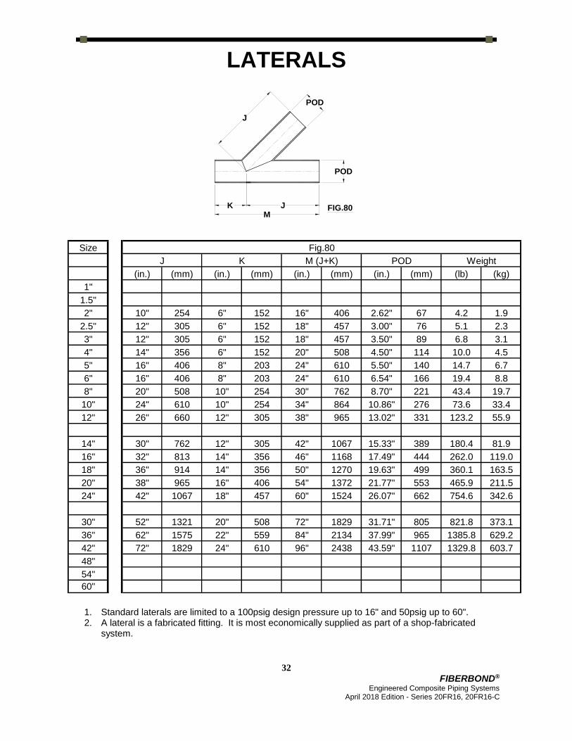
1. Standard laterals are limited to a 100psig design pressure up to 16" and 50psig up to 60". 2. A lateral is a fabricated fitting. It is most economically supplied as part of a shop-fabricated
system.
POD
POD
FIG.80J
J
MK

33
FIBERBOND® Engineered Composite Piping Systems
April 2018 Edition - Series 20FR16, 20FR16-C
REDUCING LATERAL OLETS
K
6" 6" 6" 8" 10" 10" 12" 12"
Branch Diameter
1",1.5",2" 2.5", 3" 4" 5", 6" 8" 10" 12" 14"
J2
1"
1.5"
10" 2"
12" 2.5"
12" 3" 10" 12"
14" 4" 10" 12"
16" 5" 10" 12" 14"
16" 6" 10" 12" 14" 15"
20" 8" 10" 12" 14" 16"
24" 10" 12" 13" 14" 16" 20"
26" 12" 14" 15" 16" 18" 20" 24"
30" 14" 16" 17" 18" 20" 22" 24" 26"
32" 16" 18" 19" 20" 22" 24" 26" 28" 30"
36" 18" 20" 21" 22" 24" 26" 28" 30" 32"
38" 20" 22" 23" 24" 26" 28" 30" 32" 34"
42" 24" 26" 27" 28" 30" 32" 34" 36" 38"
52" 30" 32" 33" 34" 36" 38" 40" 42" 44"
62" 36" 38" 39" 40" 42" 44" 46" 48" 50"
72" 42" 44" 45" 46" 48" 50" 52" 54" 56"
48"
54"
60"
J
Head
er
Dia
mete
r
34
FIBERBOND® Engineered Composite Piping Systems
April 2018 Edition - Series 20FR16, 20FR16-C
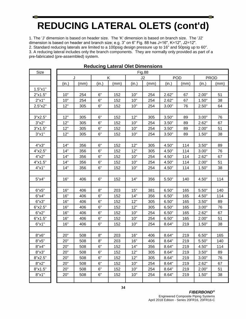
REDUCING LATERAL OLETS (cont'd) 1. The 'J' dimension is based on header size. The 'K' dimension is based on branch size. The 'J2' dimension is based on header and branch size; e.g. 3” on 6” Fig. 88 has J=16", K=12", J2=12". 2. Standard reducing laterals are limited to a 100psig design pressure up to 16" and 50psig up to 60". 3. A reducing lateral includes only the branch components. They are normally only provided as part of a pre-fabricated (pre-assembled) system.
Reducing Lateral Olet Dimensions
Size Fig.88
J K J2 POD PROD
(in.) (mm) (in.) (mm) (in.) (mm) (in.) (mm) (in.) (mm)
1.5"x1"
2"x1.5" 10" 254 6" 152 10" 254 2.62" 67 2.00" 51
2"x1" 10" 254 6" 152 10" 254 2.62" 67 1.50" 38
2.5"x2" 12" 305 6" 152 10" 254 3.00" 76 2.50" 64
3"x2.5" 12" 305 6" 152 12" 305 3.50" 89 3.00" 76
3"x2" 12" 305 6" 152 10" 254 3.50" 89 2.62" 67
3"x1.5" 12" 305 6" 152 10" 254 3.50" 89 2.00" 51
3"x1" 12" 305 6" 152 10" 254 3.50" 89 1.50" 38
4"x3" 14" 356 6" 152 12" 305 4.50" 114 3.50" 89
4"x2.5" 14" 356 6" 152 12" 305 4.50" 114 3.00" 76
4"x2" 14" 356 6" 152 10" 254 4.50" 114 2.62" 67
4"x1.5" 14" 356 6" 152 10" 254 4.50" 114 2.00" 51
4"x1" 14" 356 6" 152 10" 254 4.50" 114 1.50" 38
5"x4" 16" 406 6" 152 14" 356 5.50" 140 4.50" 114
6"x5" 16" 406 8" 203 15" 381 6.50" 165 5.50" 140
6"x4" 16" 406 6" 152 14" 356 6.50" 165 4.50" 114
6"x3" 16" 406 6" 152 12" 305 6.50" 165 3.50" 89
6"x2.5" 16" 406 6" 152 12" 305 6.50" 165 3.00" 76
6"x2" 16" 406 6" 152 10" 254 6.50" 165 2.62" 67
6"x1.5" 16" 406 6" 152 10" 254 6.50" 165 2.00" 51
6"x1" 16" 406 6" 152 10" 254 8.64" 219 1.50" 38
8"x6" 20" 508 8" 203 16" 406 8.64" 219 6.50" 165
8"x5" 20" 508 8" 203 16" 406 8.64" 219 5.50" 140
8"x4" 20" 508 6" 152 14" 356 8.64" 219 4.50" 114
8"x3" 20" 508 6" 152 12" 305 8.64" 219 3.50" 89
8"x2.5" 20" 508 6" 152 12" 305 8.64" 219 3.00" 76
8"x2" 20" 508 6" 152 10" 254 8.64" 219 2.62" 67
8"x1.5" 20" 508 6" 152 10" 254 8.64" 219 2.00" 51
8"x1" 20" 508 6" 152 10" 254 8.64" 219 1.50" 38

35
FIBERBOND® Engineered Composite Piping Systems
April 2018 Edition - Series 20FR16, 20FR16-C
REDUCING LATERAL OLETS (cont'd)
Reducing Lateral Olet Dimensions
Size Fig.88
J K J2 POD PROD
(in.) (mm) (in.) (mm) (in.) (mm) (in.) (mm) (in.) (mm)
10"x8" 24" 610 10" 254 20" 508 10.78" 274 8.64" 219
10"x6" 24" 610 8" 203 16" 406 10.78" 274 6.50" 165
10"x5" 24" 610 8" 203 16" 406 10.78" 274 5.50" 140
10"x4" 24" 610 6" 152 14" 356 10.78" 274 4.50" 114
10"x3" 24" 610 6" 152 13" 330 10.78" 274 3.50" 89
10"x2.5" 24" 610 6" 152 13" 330 10.78" 274 3.00" 76
10"x2" 24" 610 6" 152 12" 305 10.78" 274 2.62" 67
10"x1.5" 24" 610 6" 152 12" 305 10.78" 274 2.00" 51
10"x1" 24" 610 6" 152 12" 305 10.78" 274 1.50" 38
12"x10" 26" 660 10" 254 24" 610 12.92" 328 10.78" 274
12"x8" 26" 660 10" 254 20" 508 12.92" 328 8.64" 219
12"x6" 26" 660 8" 203 18" 457 12.92" 328 6.50" 165
12"x5" 26" 660 8" 203 18" 457 12.92" 328 5.50" 140
12"x4" 26" 660 6" 152 16" 406 12.92" 328 4.50" 114
12"x3" 26" 660 6" 152 15" 381 12.92" 328 3.50" 89
12"x2.5" 26" 660 6" 152 15" 381 12.92" 328 3.00" 76
12"x2" 26" 660 6" 152 14" 356 12.92" 328 2.62" 67
12"x1.5" 26" 660 6" 152 14" 356 12.92" 328 2.00" 51
12"x1" 26" 660 6" 152 14" 356 12.92" 328 1.50" 38
14"x12" 30" 762 12" 305 26" 660 15.33" 389 12.92" 328
16"x14" 32" 813 12" 305 30" 762 17.49" 444 15.33" 389
18"x16" 36" 914 14" 356 34" 864 19.63" 499 17.49" 444
20"x18" 38" 965 14" 356 38" 965 21.77" 553 19.63" 499
24"x20" 42" 1067 16" 406 44" 1118 26.07" 662 21.77" 553
30"x24" 52" 1321 18" 457 54" 1372 31.71" 805 26.07" 662
36"x30" 62" 1575 20" 508 66" 1676 37.99" 965 31.71" 805
42"x36" 72" 1829 22" 559 78" 1981 43.59" 1107 37.99" 965
48"x42"
54"x48"
60"x54"

36
FIBERBOND® Engineered Composite Piping Systems
April 2018 Edition - Series 20FR16, 20FR16-C
REDUCING LATERAL OLETS (cont'd)
Reducing Lateral Olet Weights Size Fig.88 Size Fig.88 Size Fig.88
(lb) (kg) (lb) (kg) (lb) (kg)
1.5" x 1" 8" x 6" 14.5 6.6 14" x 12" 74 34
8" x 5" 9.0 4.1
2" x 1.5" 2.2 1.0 8" x 4" 7.3 3.3 16" x 14" 95 43
2" x 1" 1.7 0.8 8" x 3" 5.4 2.5
8" x 2.5" 4.6 2.1 18" x 16" 136 62
2.5" x 2" 2.7 1.2 8" x 2" 3.7 1.7
8" x 1.5" 3.1 1.4 20" x 18" 193 88
3" x 2.5" 3.3 1.5 8" x 1" 2.4 1.1
3" x 2" 2.7 1.2 24" x 20" 252 114
3" x 1.5" 2.2 1.0 10" x 8" 31.5 14.3
3" x 1" 1.7 0.8 10" x 6" 16.0 7.3 30" x 24" 453 206
10" x 5" 10.2 4.6
4" x 3" 4.3 2.0 10" x 4" 8.3 3.8 36" x 30" 409 186
4" x 2.5" 3.6 1.6 10" x 3" 6.1 2.8
4" x 2" 3.0 1.4 10" x 2.5" 5.2 2.4 42" x 36" 698 317
4" x 1.5" 2.4 1.1 10" x 2" 4.3 2.0
4" x 1" 1.8 0.8 10" x 1.5" 3.5 1.6 48" x 42"
10" x 1" 2.7 1.2
5" x 4" 5.4 2.5 54" x 48"
12" x 10" 53.5 24.3
6" x 5" 7.8 3.5 12" x 8" 32.8 14.9 60" x 54"
6" x 4" 6.3 2.9 12" x 6" 16.7 7.6
6" x 3" 4.7 2.1 12" x 5" 10.8 4.9
6" x 2.5" 3.9 1.8 12" x 4" 8.8 4.0
6" x 2" 3.2 1.5 12" x 3" 6.5 3.0
6" x 1.5" 2.7 1.2 12" x 2.5" 5.5 2.5
6" x 1" 2.0 0.9 12" x 2" 4.5 2.0
12" x 1.5" 3.8 1.7
12" x 1" 2.9 1.3

37
FIBERBOND® Engineered Composite Piping Systems
April 2018 Edition - Series 20FR16, 20FR16-C
DUMMY LEGS, CAPS, PUP PIECES
Size Fig.90, 91
Dummy Leg Size PLOD PTHK PBOD Weight
(in.) DN (in.) (mm) (in.) (mm) (in.) (mm) (lb) (kg)
1"
1.5"
2" 2" DN50 5" 127 0.50" 13 2.62" 67 5.3 2.4
2.5" 2" DN50 5" 127 0.50" 13 2.62" 67 5.3 2.4
3" 2" DN50 5" 127 0.50" 13 2.62" 67 5.3 2.4
4" 3" DN80 6" 152 0.50" 13 3.50" 89 7.8 3.5
5" 3" DN80 6" 152 0.50" 13 3.50" 89 7.8 3.5
6" 4" DN100 7" 178 0.50" 13 4.50" 114 10.3 4.7
8" 6" DN150 9" 229 0.50" 13 6.50" 165 15.5 7.0
10" 6" DN150 9" 229 0.50" 13 6.50" 165 15.5 7.0
12" 8" DN200 12" 305 0.50" 13 8.64" 219 28.1 12.8
14" 10" DN250 14" 356 0.50" 13 10.78" 274 39.4 17.9
16" 12" DN300 16" 406 0.50" 13 12.92" 328 57.2 26.0
18" 14" DN350 18" 457 0.50" 13 15.33" 389 72.9 33.1
20" 18" ND450 22" 559 0.50" 13 19.63" 499 116.8 53.0
24" 18" DN450 22" 559 0.50" 13 19.63" 499 116.8 53.0
30" 24" DN600 28" 711 0.75" 19 26.07" 662 210.1 95.4
36" 24" DN600 28" 711 0.75" 19 26.07" 662 210.1 95.4
42" 36" DN900 40" 1016 0.75" 19 37.99" 965 332.7 151.0
48" 36" DN900 40" 1016 0.75" 19 37.99" 965 332.7 151.0
54" 48" DN1200 52" 1321 0.75" 19 49.79" 1265 432.1 196.2
60" 48" DN1200 52" 1321 0.75" 19 49.79" 1265 432.1 196.2

38
FIBERBOND® Engineered Composite Piping Systems
April 2018 Edition - Series 20FR16, 20FR16-C
DUMMY LEGS, CAPS, PUP PIECES
(cont'd) 1. Fig. 90 and Fig. 91 include the dummy leg only, not the elbow nor pipe. Dummy legs can also be placed under tees and reducers. 2. Maximum dummy leg length is 3’-0”. Specify the required leg length with the figure number. 3. Plate to be shipped loose and field installed. 6” of trim to be provided on dummy leg. 4. In prefabricated systems, the Fig.1 'Y' dimension can be as short as 1". 5. Fig.90, 91 weight is based on a nominal 3ft (0.9m) height and includes the base plate.
Caps and Pup Pieces
Size Fig.96 Fig.1
N FOD Weight Y POD
(in.) (mm) (in.) (mm) (lb) (kg) (in.) (mm) (in.) (mm)
1" 4" 1.8 1.50" 38
1.5" 4" 1.8 2.00" 51
2" 1.5" 38 2.62" 67 0.1 0.0 4" 102 2.62" 67
2.5" 1.5" 38 3.00" 76 0.2 0.1 4" 102 3.00" 76
3" 2.0" 51 3.50" 89 0.2 0.1 4" 102 3.50" 89
4" 2.5" 64 4.50" 114 0.4 0.2 6" 152 4.50" 114
5" 3.0" 76 5.50" 140 0.7 0.3 6" 152 5.50" 140
6" 3.5" 89 6.54" 166 0.9 0.4 6" 152 6.54" 166
8" 4.0" 102 8.70" 221 2.1 0.9 9" 229 8.70" 221
10" 5.0" 127 10.86" 276 3.9 1.8 12" 305 10.86" 276
12" 6.0" 152 13.02" 331 6.6 3.0 14" 356 13.02" 331
14" 6.5" 165 15.45" 392 10.3 4.7 17" 432 15.43" 392
16" 7.0" 178 17.61" 447 15.2 6.9 19" 483 17.59" 447
18" 8.0" 203 19.77" 502 21.5 9.7 21" 533 19.75" 502
20" 9.0" 229 21.93" 557 29.2 13.3 24" 610 21.91" 557
24" 10.5" 267 26.25" 667 49.8 22.6 28" 711 26.23" 666
30" 10.5" 267 31.85" 809 61.7 28.0 19" 483 31.83" 808
36" 10.5" 267 38.15" 969 106.1 48.2 22" 559 38.15" 969
42" 12.0" 305 43.73" 1111 114.1 51.8 15" 381 43.73" 1111
48" 13.5" 343 49.93" 1268 164.3 74.6 15" 381 49.93" 1268
54" 20" 508 55.21" 1402
60" 16.5" 419 61.31" 1557 171.9 78.0 20" 508 61.31" 1557

39
FIBERBOND® Engineered Composite Piping Systems
April 2018 Edition - Series 20FR16, 20FR16-C
THREADED CONNECTIONS
For Series 20FR16 and 20FR16-C, the threaded options are: 1) the Figure 94 Flanged Saddle with drilled-and-tapped alloy blind flange and 2) the Figure 47JF threaded alloy MNPT. The Figure 97 threaded FRP FNPT is no longer a standard product. 1. Fig.94: The most reliable and heavy-duty solution for threaded connections is to use
an FRP flange and bolt an alloy (316SS, 90/10 Cu-Ni, Gr. 2 Ti, etc.) blind flange that is drilled-and-tapped for the NPT size. This type of connection has been used for many years and is the most durable and toughest solution.
2. Fig.47JF: To eliminate the need for a bolted connection, the Figure 47JF MNPT alloy saddle is available. Alloy material choices include 316SS, 90/10 Cu-Ni, Titanium, and Monel. Other alloy materials may be available. This alloy MNPT is designed for connections to spray nozzles in deluge systems and can also be used for connecting to vents, drains, and instruments. Due to the large bending moment that could be applied, it is not recommended that the Fig.47JF MNPT be used to connect directly to long runs of threaded alloy piping. Note: the alloy MNPT is permanently bonded to the FRP piping.
Notes: 1. The Fig.47JF sizes are 0.50", 0.75", 1.0", 1.25", and 1.5" MNPT. The 'H2' dimension is approximate and will vary based on the pipe wall thickness. Material choices include 316SS, 90/10 Cu-Ni, Titanium, Monel, and others. 2. The Fig.47JF olet fitting includes only the branch components. Unless purchased as part of a pre-fabricated (pre-assembled) system, it does require some assembly and bonding work. 3. The Fig.94 threaded alloy blind includes the drilled-and-tapped alloy blind flange only. The branch size is 2" diameter, standard. Other branch sizes are available upon request. Material choices for the alloy blind flange include 316SS, 90/10 Cu-Ni and others. 4. For Fig.47JF, CMODs are: 0.56" (14.3mm) for 1/2", 0.81" (20.6mm) for 3/4", 1.06" (27.0mm) for 1", 1.31" (33.3mm) for 1 1/4", and 1.56" (39.7mm) for 1 1/2"MNPTs.

40
FIBERBOND® Engineered Composite Piping Systems
April 2018 Edition - Series 20FR16, 20FR16-C
THREADED CONNECTIONS (cont'd)
Threaded Connection Weights
Size Fig.47JF Fig.94
(lb) (kg) (lb) (kg)
1"x1/2", 1.5"x1/2", …, 60"x1/2" 1.6 0.7
1"x3/4", 1.5"x3/4", …, 60"x3/4" 1.7 0.8
1.5"x1", 2"x1", …, 60"x1" 2.5 1.2
1.5"x1.25", 2"x1.25", …, 60"x1.25" 2.6 1.2
2"x1.5", 2.5"x1.5", …, 60"x1.5" 2.7 1.2
2.5"x2", 3"x2", …, 60"x2" 6.1 2.8
Size Fig.47JF,94 Fig.47JF Fig.94
POD H2 H
(in.) (mm) (in.) (mm) (in.) (mm)
0.5"
0.75"
1.0" 1.50" 38 4.75" 121
1.5" 2.00" 51 5.00" 127
2" 2.62" 67 5.25" 133 7.00" 178
2.5" 3.00" 76 5.50" 140 7.25" 184
3" 3.50" 89 5.75" 146 7.50" 191
4" 4.50" 114 6.25" 159 8.00" 203
5" 5.50" 140 6.75" 171 8.50" 216
6" 6.50" 165 7.31" 186 9.00" 229
8" 8.64" 219 8.38" 213 10.00" 254
10" 10.78" 274 9.44" 240 11.00" 279
12" 12.92" 328 10.50" 267 12.00" 305
14" 15.33" 389 11.56" 294 13.00" 330
16" 17.49" 444 12.63" 321 14.00" 356
18" 19.63" 499 13.69" 348 15.00" 381
20" 21.77" 553 14.56" 370 16.00" 406
24" 26.07" 662 16.63" 422 18.00" 457
30" 31.71" 805 19.75" 502 21.00" 533
36" 37.99" 965 22.88" 581 24.00" 610
42" 43.59" 1107 25.56" 649 27.00" 686
48" 49.79" 1265 28.63" 727 30.00" 762
54" 55.13" 1400 31.69" 805 33.00" 838
60" 61.21" 1555 34.63" 879 36.00" 914

OVER 40 YEARS EXPERIENCE IN SUCCESSFUL
APPLICATIONS OF FIBERGLASS PIPE SYSTEMS.
Manufactured by
Future Pipe Industries, Inc.
An ISO9001 Certified Company
15915 Perkins Road
Baton Rouge, LA 70810 U.S.A.
www.fiberbond.com
Phone
+1 (225) 752-2705
Toll Free (U.S.A.)
800-752-7473