Embed Size (px)
Citation preview

Series 525 FloppyTapeCartridge Tape Drive
Product Description

1
1 INTRODUCTION 1-11.1 Scope 1-11.2 Terminology 1-11.3 General Description 1-31.4 Features 1-3
2 SPECIFICATIONS & RELIABILITY 2-12.1 Tape Specifications 2-12.1.1 Recording Times 2-12.1.2 Positioning 2-12.2 Reliability 2-22.2.1 Mean Time Between Failures 2-22.2.2 Mean Time To Repair 2-22.2.3 Preventive Maintenance 2-22.3 Data Integrity 2-32.3.1 Media 2-32.3.2 Recoverable Read Errors 2-32.3.3 Non-Recoverable Read Errors 2-32.3.4 Power Loss 2-3
3 FUNCTIONAL CHARACTERISTICS 3-13.1 General Description 3-13.2 Read/Write & Control Electronics 3-13.3 Tape Drive Mechanism 3-33.4 Read/Write Head Positioning Mechanism 3-3
4 FUNCTIONAL DESCRIPTION 4-14.1 Power Sequencing 4-14.2 Stream Selection 4-14.3 Head Load/Motor On 4-24.4 Segment Accessing 4-24.5 Step Out/Step In 4-44.6 Read Operation 4-44.7 Write Operation 4-54.8 Recording Format 4-6
5 INTERFACE SIGNALS 5-15.1 Drive Interface 5-15.2 Interface Signal Levels 5-45.3 Input Control Signals 5-45.4 Output Control Signals 5-55.5 Data Line Signals 5-65.5.1 Read Data Signal 5-65.5.2 Write Data Signal 5-7
Cipher Data Products, Inc. reservesthe right to change specificationswithout notice.Copyright 1984
TABLE OF CONTENTS
Section Page

2
6 PHYSICAL INTERFACE CONNECTION 6-16.1 Interface Connector Locations 6-16.2 Signal Connector Dimensions 6-16.3 Recommended Cables and Connectors 6-26.4 Termination 6-26.5 Frame Ground 6-2
7 PHYSICAL CHARACTERISTICS 7-17.1 Mechanical Dimensions 7-17.2 Weight 7-17.3 Mounting 7-1
8 ENVIRONMENTAL CHARACTERISTICS/POWER REQUIREM ENTS 8-18.1 Temperature 8-18.2 Humidity 8-18.3 Altitude 8-18.4 Vibration 8-18.5 Shock 8-18.6 Air Quality 8-18.7 Acoustical Noise 8-28.8 D C Power 8-28.9 Heat Dissipation 8-28.10 Cooling 8-2
9 APPLICATION NOTES 9-19.1 General 9-19.2 Hardware Considerations 9-29.3 Encoding Techniques 9-49.3.1 Single Density (FM) 9-49.3.2 Double Density (MFM) 9-49.4 Software Considerations 9-49.4.1 Drive Selection 9-49.4.2 Addressable Tracks (Segments) 9-49.4.3 Number of Sectors 9-S9.4.4 Stream Formatting 9-59.4.5 I/O Buffering & Sector Interleaving 9-59.4.6 Retension Pass 9-69.5 Formatting 9-69.5.1 Format Description 9-69.5.2 Data Integrity 9-99.5.3 Format Operation 9-99.6 Access Timing 9-129.6.1 Stream To Stream 9-129.6.2 Segment To Segment 9-129.6.3 Read Reposition 9-14
TABLE OF CONTENTS (Continued)
PageSection

3
APPENDIX A CONFIGURATION TABLES A-1
A.1 Jumper Options A-1A.2 Stream Selection Tables A-1A.3 Service Aids A-4A.3.1 Continuous Forward/Reverse A-4A.3.2 Stream Positioning - All Streams A-4A.3.3 Stream Positioning - Streams 0 & 4 A-4A.3.4 Cyclic Tape Motion A-4
APPENDIX B OPERATING PARAMETER CONSIDERATIONS B-1
B. 1 Time Outs B-1B.2 Read After Write B-1B.3 Reinstruct Timing B-2B.4 Sectors/Segment Counts B-2B.5 Stream (Drive) Selection B-2
TABLE OF CONTENTS (Continued)

4
LIST OF ILLUSTRATIONS
Figure Page
1-1 525 FloppyTape Drive 1-11-2 The Evolution of FloppyTape 1-2
3-1 525 Functional Block Diagram 3-23-2 Component Location Layout 3-33-3 Read/Write Head Assembly 3-3
4-1 525 Physical Tape Layout 4-14-2 525 Stream Partitioning Layout 4-24-3 Stream Access Flowchart 4-34-4 Random Segment Access Timing 4-44-5 Read Timing 4-54-6 Write Timing 4-6
5-1 525 Drive Interface - SA450 5-15-2 525 Drive Interface - SA850 5-25-3 I/O Listing 5-35-4 Interface Signal Driver/Receiver 5-45-5 Read Data Signal- FM & MFM 5-65-6 Write Data Signal - FM & MFM 5-7
6-1 525 Interface Connectors - SA450 6-16-2 J 1 Interface Connector Dimensions - SA450 6-16-3 J1 Interface Connector Dimensions - SA850 6-2
7-1 525 Dimensions 7-1
9-1 Typical Host System (Block Diagram) 9-19-2 Typical Floppy Disk Host Controller 9-29-3 525 Controller Example - SA450 9-39-4 FM vs. M FM Recording 9-59-5 IBM System 34 Format Example 9-89-6 Format Flowchart 9-109-7 Verification Pass Flowchart 9-109-8 Stream Format Timing 9-119-9 Head Positioning 9-129-10 Contiguous Segment-to-Segment Timing 9-139-11 Read Reposition Timing 9-14
1-1
SECTION 1INTRODUCTION
1.1 SCOPEThis manual describes the electrical and mechanicalcharacteristics of Cipher Data Products’ 525 FloppyTape®1/4-inch cartridge tape drive. It contains the timing,electrical, and mechanical specifications f or the 525,which is available with a data rate of 500 KHz with SA450or SA850 interface, or a 250 KHz rate with a SA450interface. It also recommends the formats and circuitrynecessary to interface the 525 to a host controller.
The information in this manual is correct at the time ofpublication, but is subject to change without notice. Thisinformation is the exclusive property of Cipher DataProducts, Inc. and shall not be reproduced in any mannerwithout the written permission of Cipher Data Products,Inc.
1.2 TERMINOLOGYThe following new or, possibly, unfamiliar terms relateto FloppyTape technology:
• Sector - smallest unit of addressable memory located within a segment.
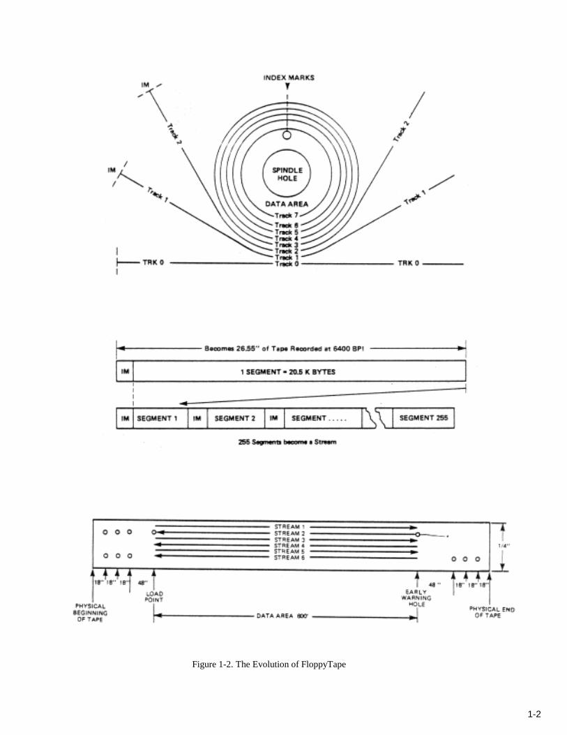
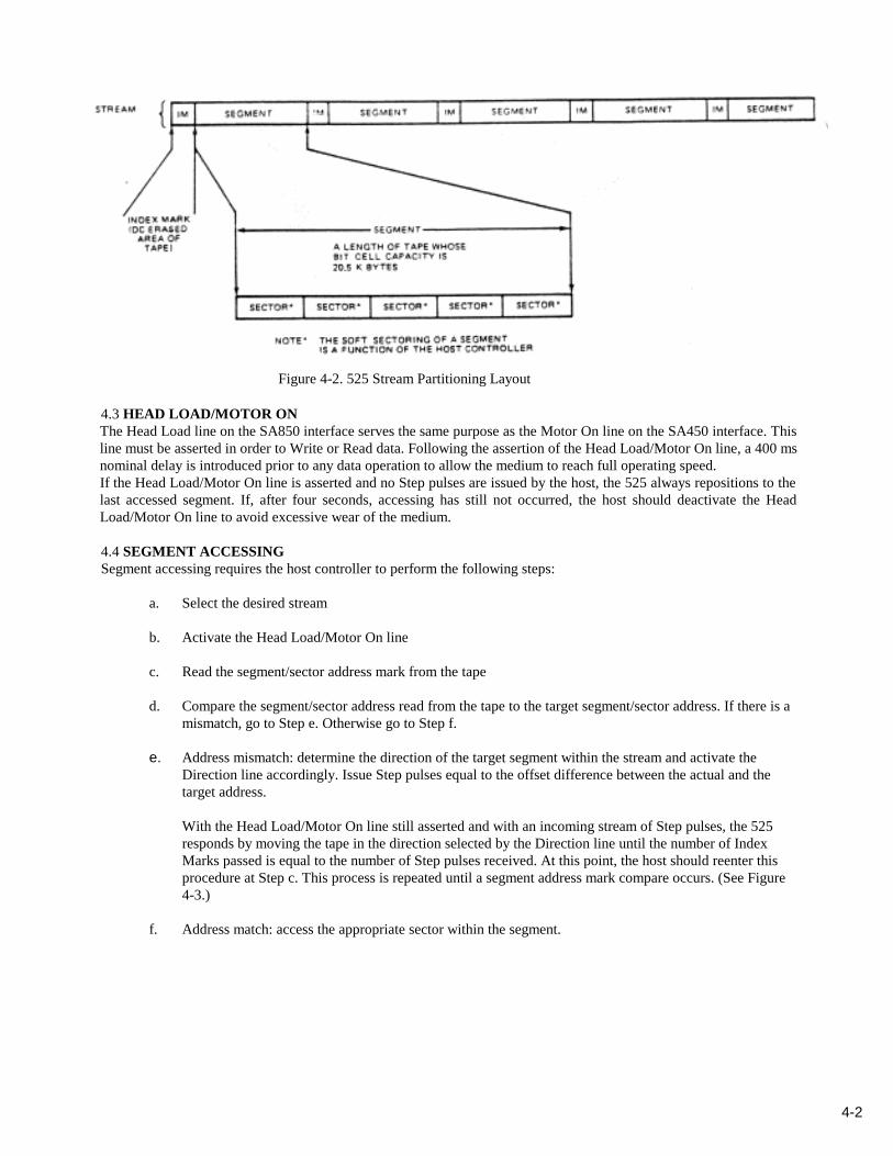
• Segment - a fixed length of tape that emulates a floppy disk track. Each segment is 26.55 inches, and has thecapacity (unformatted) of 20.5 kilobytes. See Figure 1-2.
• Stream - one of six physical bit serial tracks recorded on tape. Each stream contains 255 segments (0-254). SeeFigure 1-2.
• Index Pulse- a signal sent to the host controller by the 525 to indicate the detection of an Index Mark. An Indexpulse can be used by the host controller to initialize segment operations.
• Index Mark - a portion of a stream in which the oxide is saturated in one direction. An Index Mark is used for thelogical separation of segments. See Figure 1-2.
• Upstream - a position on tape that is between the present location and the logical End of Stream (EOS). SeeFigure 1-2.
• Downstream - a position on tape that is between the present location and the logical Beginning of Stream (BOS).See Figure 1-2.
• Host Controller - the hardware required to interface the 525 to the host computer.
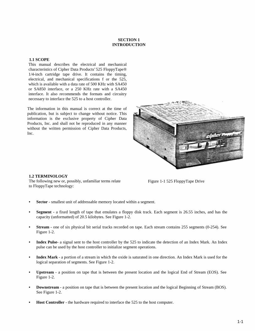
Figure 1-1 525 FloppyTape Drive
1-2
Figure 1-2. The Evolution of FloppyTape
1-3
1.3 GENERAL DESCRIPTIONThe Cipher 525 FloppyTape cartridge tape drive is a low cost, computer data storage tape drive, employing the 3MDC600A or any other Cipher approved 1/4-inch cartridge tape media. The 525 emulates the industry standard SA850or SA450 interface and responds to common floppy disk drive commands. Emulation of a floppy disk drive isaccomplished by the FloppyTape’s on-board Z8603 microprocessor. Data is recorded in a bit serial manner on eachone of the six streams on the tape. Streams are selected by the host system via the four Drive Select and Side Selectlines supported by the standard SA850 or SA450 bus. The host treats each stream as a logical disk surface. Prior to anystream access, the host system must select one of the six logical surfaces. Actual physical stream selection isaccomplished by first having the Z8603 microprocessor interpret the Drive Select and Side Select lines, thenpositioning the Read/Write head on the selected stream. Each stream has an unformatted capacity of 5.2 megabytes.
Emulation of a floppy disk track is achieved by partitioning a stream into 26-inch segments. Segments are separated byDC saturated portions of tape referred to as Index Marks (IMs). Stream partitioning into segments by IMs is done bythe Z8603 microprocessor during a stream format operation initiated by the host system. Following the formatoperation, the FloppyTape uses the IMs to generate the Index Pulse signal seen by the host on the interface. IMs arealso used by the FloppyTape to count the 26inch increments of tape, when a segment seek operation is initiated by thehost system controller. The unformatted capacity of a segment is 20.5 Kbytes (approximately twice the capacity of an8-inch floppy disk track). Segments are accessed by the host system using the floppy disk protocol step and directionlines from the floppy disk controller.
1.4 FEATURESThe main features of the 525 FloppyTape include:
• Standard ANSI cartridge mounting
• Precise head stepping
• SA450 or SA850 floppy disk interfaces
• Operable with existing floppy disk controller chips
• No AC requirements
• 5-1/4-inch form factor
• High capacity storage (32 MB)
• Soft sector type floppy disk format
• Enclosed/removable media
• Low maintenance

2-1
SECTION 2SPECIFICATIONS & RELIABILITY
2.1 TAPE SPECIFICATIONSTape Speed/Transfer Rate:* 78 ips/500 Kbits/sec
or39 ips/250 Kbits/sec
Ramp Time: 350 ms
Tape Speed VariationLow Frequency: Less than ±2%Instantaneous: Less than ±696
Write Pre-compensation: 200 ns @ 500 Kbits/sec250 ns @ 250 Kbits/sec
MFM Recording Density: 6,400 bpi nominal
Unformatted Capacity (MFM Recording)Segment: 26.55 inches = 20.5 Kbytes max.Stream: 255 segments = 5.2 hibytesCartridge: 6 streams = 31.3 Mbytes
Recording Tracks: 6
Recording Method: NRZ
Interface CodeRecommended: Modified Frequency Modulation (MFM)Available: Frequency Modulation (FM)
2.1.1 Recording Times
78 ips (500 Kbits/sec) 0.333 sec/segment93 sec/stream558 sec/cartridge
39 ips (250 Kbits/sec) 0.666 sec/segment186 sec/stream1,116 sec/cartridge
2.1.2 PositioningMethod: Multi-position stepper motor
*Transfer rate is tape drive dependent.

2-2
2.2 RELIABLITY2.2.1 Mean Time Between Failures (MTBF)The MTBF for a drive is defined as follows:
MTBF = Power On HoursNumber of Equipment Failures
Definitions
Failures caused by operator error, or an out-of-specification operation, are not counted as failures.
Product Workload is stated in terms of a unit duty cycle, and is defined as actual tape motion time divided by totalpower-on time.
Infant mortality failures which occur within the first 100 hours of power-on time after site installation are notconsidered in the MTBF calculations.
The sample size must be greater than 100 units for the purpose of MTBF calculation.
Production and design maturity improvements allow the MTBF rate to be achieved 18 months from start of production.In the interim the actual MTBF might be lower. The minimum MTBF for the 525 is:
2.2.2 Mean Time To Repair (MTTR)MTTR is defined as the time for an adequately trained and competent serviceman to diagnose and correct a malfunctionat the subassembly level.
The MTTR is expected to be 15 minutes.
2.2.3 Preventive Maintenance (PM)
The 525 requires no service call related PM. The hours of required operator PM are related to the product workload.

2-3
This preventive maintenance, at a minimum, involves cleaning the tape path, including the recording head and thedrive roller surface.
2.3 DATA INTEGRITYErrors attributed to operator mishandling of the tape cartridge, or errors on the cartridge which can be detected andflagged during formatting, are not included in determining error rates.
2.3.1 MediaOnly cartridges from Cipher approved sources may be used, such as the 3M DC600A. Properly handled, the cartridgecan be used for at least 5,000 full length passes. (BOT to EOT and back to BOT is considered 2 passes.)
2.3.2 Recoverable Read ErrorsA recoverable error (soft error) is one which may be corrected by no more than 10 reread attempts. Data patterns, tapeposition, and Read/Write head position do not affect data error rate performance.The recoverable read error rate for the 525 is less than 1 in 109 bits.
2.3.3 Non-Recoverable Read ErrorsA non-recoverable read error (hard error) is one which cannot be corrected by 10 re-read attempts. Thenon-recoverable read error rate for the 525 is less than 1 in 1011 bits.
2.3.4 Power LossAccidental loss of DC power will not result in any component failure.

3-1
SECTION 3FUNCTIONAL CHARACTERISTICS
3.1 GENERAL DESCRIPTIONThe 525 FloppyTape 1/4-inch cartridge tape drive consists of Read/Write electronics, control logic, tape drivemechanism, head positioning mechanism, and the Read/Write head. These components perform the followingfunctions:
• Interpret, generate, and emulate floppy disk drive control signals• Position the Read/Write head on the logically selected stream• Monitor and control tape speed• Read and Write data
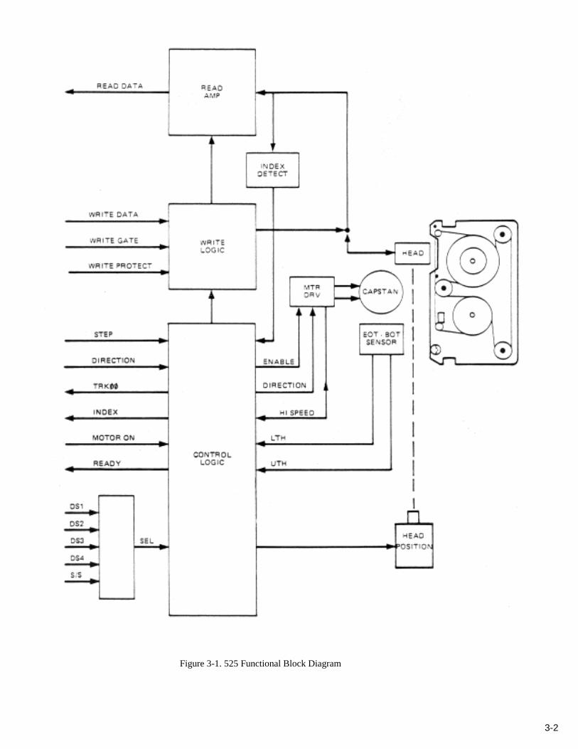
Figure 3-1 is a block diagram of the 525 FloppyTape. The host system interfaces the 525 through the control and datasignal bus. The control signals are interpreted, and appropriate action is initiated by the tape motion control logic.
Tape is transported across the Read/Write head in both directions by a direct-drive DC capstan motor. The built-intachometer circuit provides feedback to the control electronics for constant motor speed adjustment.
A photo detector senses the Beginning Of Tape (BOT), the Early Warning (EW), and the End Of Tape (EOT) holes.The on-board microprocessor initiates subsequent control actions.
The Write protect circuitry guards against accidental alterations of recorded data inhibiting the Write electronics whenthe cartridge tumbler is in the "safe" position.
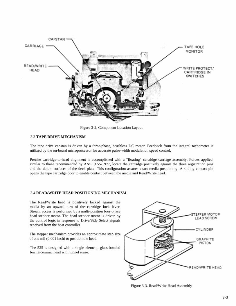
Figure 3-2 shows the physical locations of these components on the 525 chassis.
3.2 READ/WRITE & CONTROL ELECTRONICSThe Read/Write and control electronics are located on a single Printed Circuit Board (PCB). The PCB componentsinclude the following circuits:
• Index Detector/Generator• Write Current Driver• Read Amplifier and Transition Detector• Write Protect Logic• Logical Drive/Stream Selection• Tape Speed/Capstan Control• Tape Hole Monitor
3-2
Figure 3-1. 525 Functional Block Diagram
3-3
Figure 3-2. Component Location Layout
3.3 TAPE DRIVE MECHANISM
The tape drive capstan is driven by a three-phase, brushless DC motor. Feedback from the integral tachometer isutilized by the on-board microprocessor for accurate pulse-width modulation speed control.
Precise cartridge-to-head alignment is accomplished with a "floating" cartridge carriage assembly. Forces applied,similar to those recommended by ANSI 3.55-1977, locate the cartridge positively against the three registration pinsand the datum surfaces of the deck plate. This configuration assures exact media positioning. A sliding contact pinopens the tape cartridge door to enable contact between the media and Read/Write head.
3.4 READ/WRITE HEAD POSITIONING MECHANISM
The Read/Write head is positively locked against themedia by an upward turn of the cartridge lock lever.Stream access is performed by a multi-position four-phasehead stepper motor. The head stepper motor is driven bythe control logic in response to Drive/Side Select signalsreceived from the host controller.
The stepper mechanism provides an approximate step sizeof one mil (0.001 inch) to position the head.
The 525 is designed with a single element, glass-bondedferrite/ceramic head with tunnel erase.
Figure 3-3. Read/Write Head Assembly
4-1
SECTlON 4FUNCTIONAL DESCRIPTION
4.1 POWER SEQUENCING
The DC voltage (+5V, +12V) can be applied in any sequence. However, in order to maintain data integrity duringpower-up, the Write Gate line must be held inactive, or the cartridge lock lever must be in the open position. On apower-up- sequence, or the insertion of a new cartridge, the drive automatically performs a retension pass of the tape,leaving the medium positioned at Stream 1, Segment 0. (See Paragraph, 9.4.6)
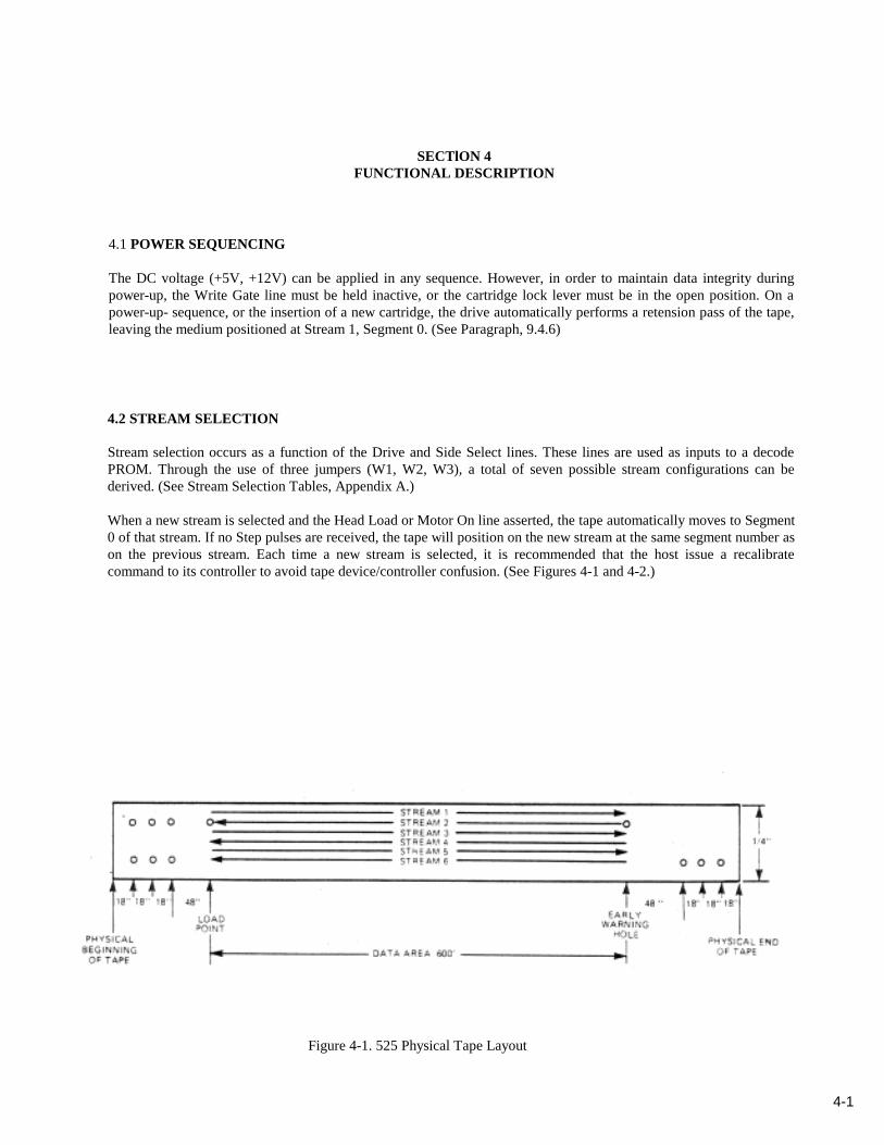
4.2 STREAM SELECTION
Stream selection occurs as a function of the Drive and Side Select lines. These lines are used as inputs to a decodePROM. Through the use of three jumpers (W1, W2, W3), a total of seven possible stream configurations can bederived. (See Stream Selection Tables, Appendix A.)
When a new stream is selected and the Head Load or Motor On line asserted, the tape automatically moves to Segment0 of that stream. If no Step pulses are received, the tape will position on the new stream at the same segment number ason the previous stream. Each time a new stream is selected, it is recommended that the host issue a recalibratecommand to its controller to avoid tape device/controller confusion. (See Figures 4-1 and 4-2.)
Figure 4-1. 525 Physical Tape Layout
4-2
Figure 4-2. 525 Stream Partitioning Layout
4.3 HEAD LOAD/MOTOR ONThe Head Load line on the SA850 interface serves the same purpose as the Motor On line on the SA450 interface. Thisline must be asserted in order to Write or Read data. Following the assertion of the Head Load/Motor On line, a 400 msnominal delay is introduced prior to any data operation to allow the medium to reach full operating speed.If the Head Load/Motor On line is asserted and no Step pulses are issued by the host, the 525 always repositions to thelast accessed segment. If, after four seconds, accessing has still not occurred, the host should deactivate the HeadLoad/Motor On line to avoid excessive wear of the medium.
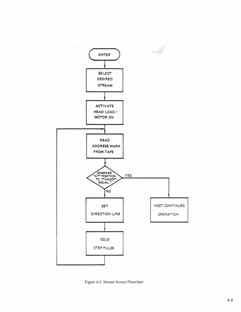
4.4 SEGMENT ACCESSINGSegment accessing requires the host controller to perform the following steps:
a. Select the desired stream
b. Activate the Head Load/Motor On line
c. Read the segment/sector address mark from the tape
d. Compare the segment/sector address read from the tape to the target segment/sector address. If there is amismatch, go to Step e. Otherwise go to Step f.
e. Address mismatch: determine the direction of the target segment within the stream and activate theDirection line accordingly. Issue Step pulses equal to the offset difference between the actual and thetarget address.
With the Head Load/Motor On line still asserted and with an incoming stream of Step pulses, the 525responds by moving the tape in the direction selected by the Direction line until the number of IndexMarks passed is equal to the number of Step pulses received. At this point, the host should reenter thisprocedure at Step c. This process is repeated until a segment address mark compare occurs. (See Figure4-3.)
f. Address match: access the appropriate sector within the segment.
4-3
Figure 4-3. Stream Access Flowchart
4-4
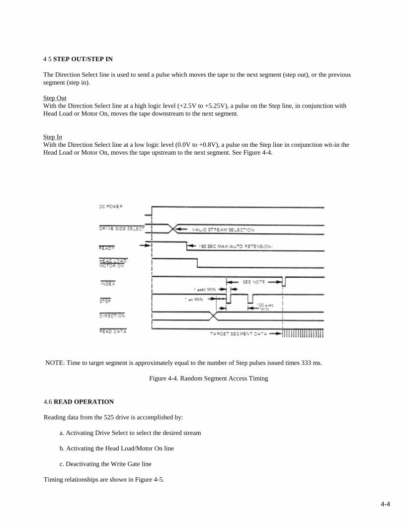
4 5 STEP OUT/STEP IN
The Direction Select line is used to send a pulse which moves the tape to the next segment (step out), or the previoussegment (step in).
Step OutWith the Direction Select line at a high logic level (+2.5V to +5.25V), a pulse on the Step line, in conjunction withHead Load or Motor On, moves the tape downstream to the next segment.
Step InWith the Direction Select line at a low logic level (0.0V to +0.8V), a pulse on the Step line in conjunction wit-in theHead Load or Motor On, moves the tape upstream to the next segment. See Figure 4-4.
NOTE: Time to target segment is approximately equal to the number of Step pulses issued times 333 ms.
Figure 4-4. Random Segment Access Timing
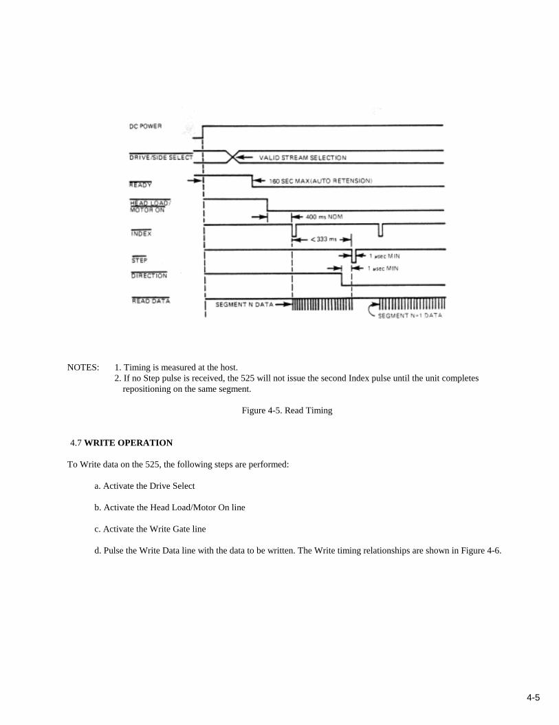
4.6 READ OPERATION
Reading data from the 525 drive is accomplished by:
a. Activating Drive Select to select the desired stream
b. Activating the Head Load/Motor On line
c. Deactivating the Write Gate line
Timing relationships are shown in Figure 4-5.
4-5
NOTES: 1. Timing is measured at the host.2. If no Step pulse is received, the 525 will not issue the second Index pulse until the unit completes
repositioning on the same segment.
Figure 4-5. Read Timing
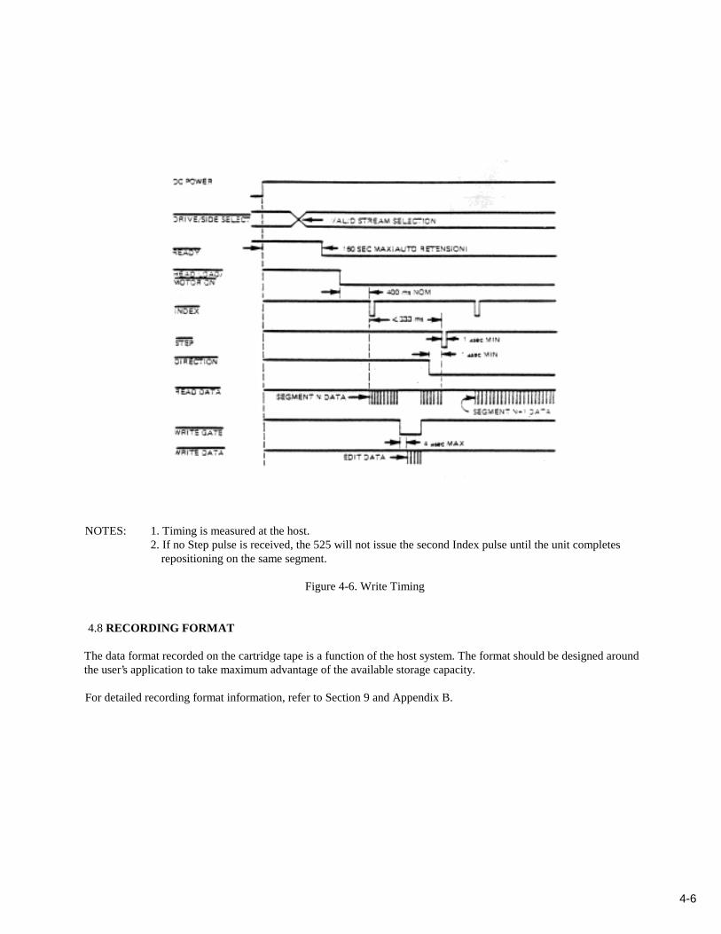
4.7 WRITE OPERATION
To Write data on the 525, the following steps are performed:
a. Activate the Drive Select
b. Activate the Head Load/Motor On line
c. Activate the Write Gate line
d. Pulse the Write Data line with the data to be written. The Write timing relationships are shown in Figure 4-6.
4-6
NOTES: 1. Timing is measured at the host.2. If no Step pulse is received, the 525 will not issue the second Index pulse until the unit completes
repositioning on the same segment.
Figure 4-6. Write Timing
4.8 RECORDING FORMAT
The data format recorded on the cartridge tape is a function of the host system. The format should be designed aroundthe user’s application to take maximum advantage of the available storage capacity.
For detailed recording format information, refer to Section 9 and Appendix B.
5-1
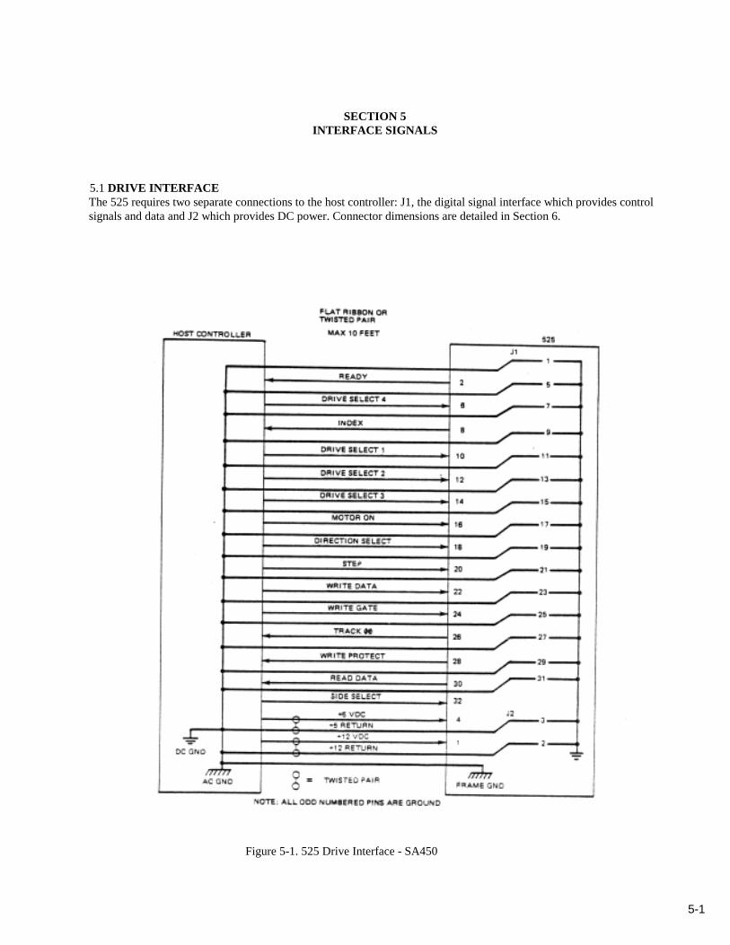
SECTION 5INTERFACE SIGNALS
5.1 DRIVE INTERFACEThe 525 requires two separate connections to the host controller: J1, the digital signal interface which provides controlsignals and data and J2 which provides DC power. Connector dimensions are detailed in Section 6.
Figure 5-1. 525 Drive Interface - SA450
5-2
Figure 5-2. 525 Drive Interface - SA850
5-3
Figure 5-3. I/0 Listing
5-4
5.2 INTERFACE SIGNAL LEVELS
True = Logical 0 = Vin ±0.0 to +0.8V@ Iin = 40 ma (max)
False = Logical 1 = Vin +2.5V to 5.25V@ Iin = 0 ma
Input Impedance = 150 oh ms
Figure 5-4. Interface Signal Driver/Receiver
5.3 INPUT CONTROL SIGNALS
Drive SelectThe four Drive Select lines (DS1 - DS4), used with the Side Select (SS) line, and the configuration jumpers W1, W2,W3, allow selection of one of six logical drives. When a particular drive is selected, the head moves to the appropriatestream and the microprocessor is enabled to scan and respond to other control signals.
Head Load/Motor OnWhen the Head Load (HLD) or Motor On (MTON) line, and Drive Select (DS) lines are asserted by the hostcontroller, the capstan on the selected drive is enabled and tape motion begins.
Direction SelectThe Direction Select (DIRC) line is used by the 525 to control the direction of tape movement. If this line is low, itcauses the tape to move upstream. If it is high, it causes the tape to move downstream.

5-5
StepA pulse on the Step line (STP) causes the tape to move one segment from its current position in the direction controlledby the DIRC line.
DIRC = I Tape motion towards logical Segment 0.DIRC = 0 Tape motion towards logical Segment 254.
Write GateThe Write Gate (WGT) line allows the host to disable the Step function and enable the Write drivers. A false (high)level on this line enables the Read output to the Read amplifier section so data may be read.
5.4 OUTPUT CONTROL SIGNALS
Track 00A logic low level on the Track line (TR00) indicates the 525 is at, or going to, the first segment (00) of the selectedstream.
IndexA pulse on the Index (INDX) line indicates that the drive is at the beginning of a segment in the selected stream. Thesegment time from Index Mark to Index Mark in a write format routine is 333 milliseconds.
Write Protect SignalA low on the Write Protect (WPT) line indicates that the safe tumbler on the cartridge has been manually set. The 525Write circuits are also disabled under this condition.
5-6
5.5 DATA LINE SIGNALS5.5.1 Read Data Signal
While reading, this line provides a 300 ns pulse for each flux transition detected on the tape.
FM Recording
MFM Recording
Figure 5-5. Read Data Signal - FM & MFM
5-7
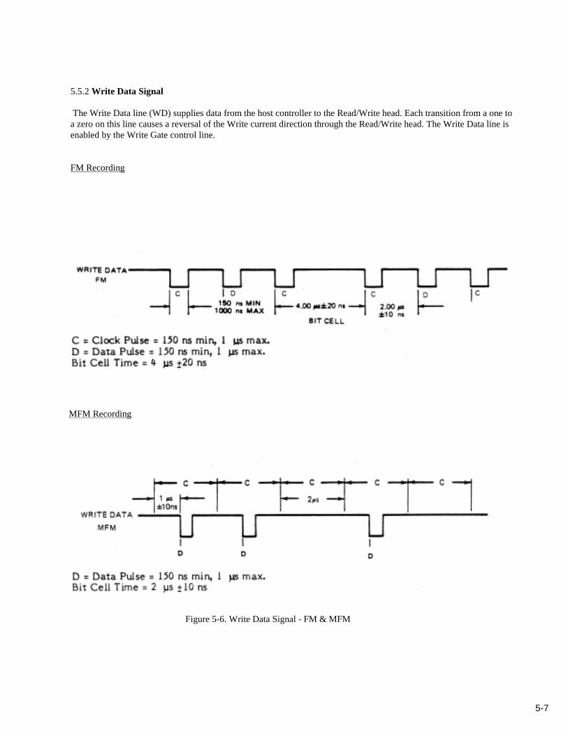
5.5.2 Write Data Signal
The Write Data line (WD) supplies data from the host controller to the Read/Write head. Each transition from a one toa zero on this line causes a reversal of the Write current direction through the Read/Write head. The Write Data line isenabled by the Write Gate control line.
FM Recording
MFM Recording
Figure 5-6. Write Data Signal - FM & MFM
6-1
SECTION 6PHYSICAL INTERFACE CONNECTION
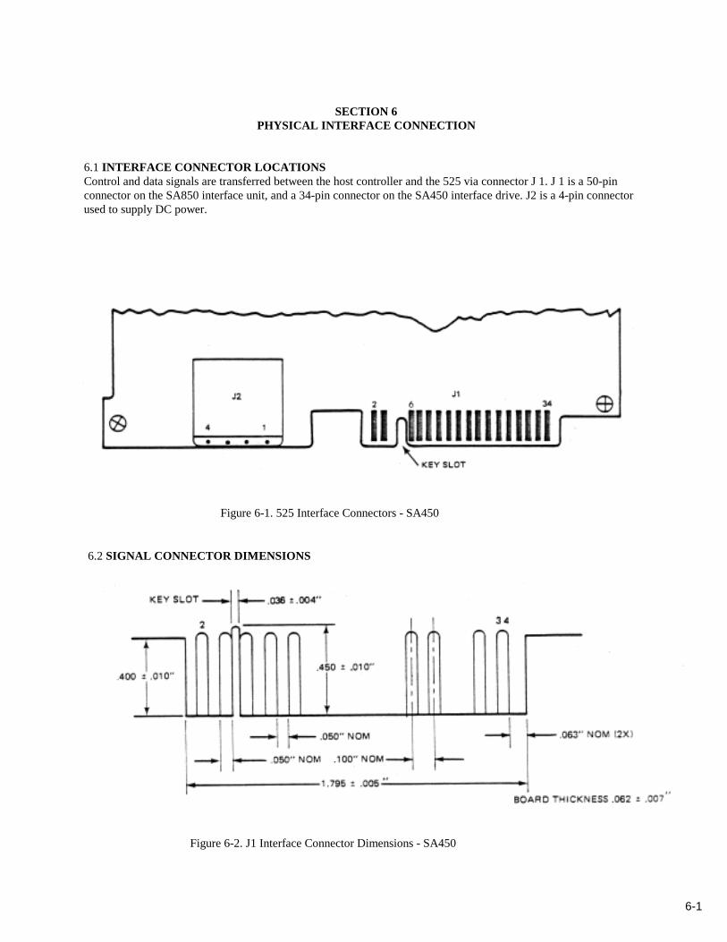
6.1 INTERFACE CONNECTOR LOCATIONSControl and data signals are transferred between the host controller and the 525 via connector J 1. J 1 is a 50-pinconnector on the SA850 interface unit, and a 34-pin connector on the SA450 interface drive. J2 is a 4-pin connectorused to supply DC power.
Figure 6-1. 525 Interface Connectors - SA450
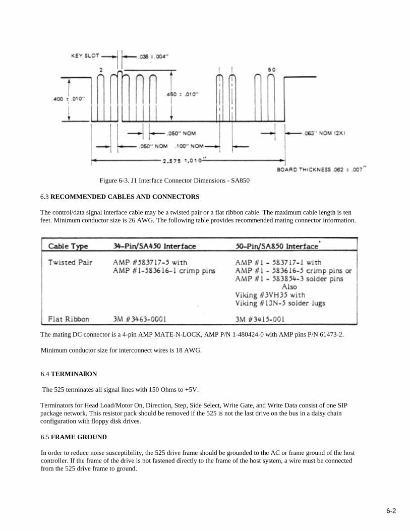
6.2 SIGNAL CONNECTOR DIMENSIONS
Figure 6-2. J1 Interface Connector Dimensions - SA450
6-2
Figure 6-3. J1 Interface Connector Dimensions - SA850
6.3 RECOMMENDED CABLES AND CONNECTORS
The control/data signal interface cable may be a twisted pair or a flat ribbon cable. The maximum cable length is tenfeet. Minimum conductor size is 26 AWG. The following table provides recommended mating connector information.
The mating DC connector is a 4-pin AMP MATE-N-LOCK, AMP P/N 1-480424-0 with AMP pins P/N 61473-2.
Minimum conductor size for interconnect wires is 18 AWG.
6.4 TERMINAllON
The 525 terminates all signal lines with 150 Ohms to +5V.
Terminators for Head Load/Motor On, Direction, Step, Side Select, Write Gate, and Write Data consist of one SIPpackage network. This resistor pack should be removed if the 525 is not the last drive on the bus in a daisy chainconfiguration with floppy disk drives.
6.5 FRAME GROUND
In order to reduce noise susceptibility, the 525 drive frame should be grounded to the AC or frame ground of the hostcontroller. If the frame of the drive is not fastened directly to the frame of the host system, a wire must be connectedfrom the 525 drive frame to ground.
7-1
SECTION 7PHYSICAL CHARACTERISTICS
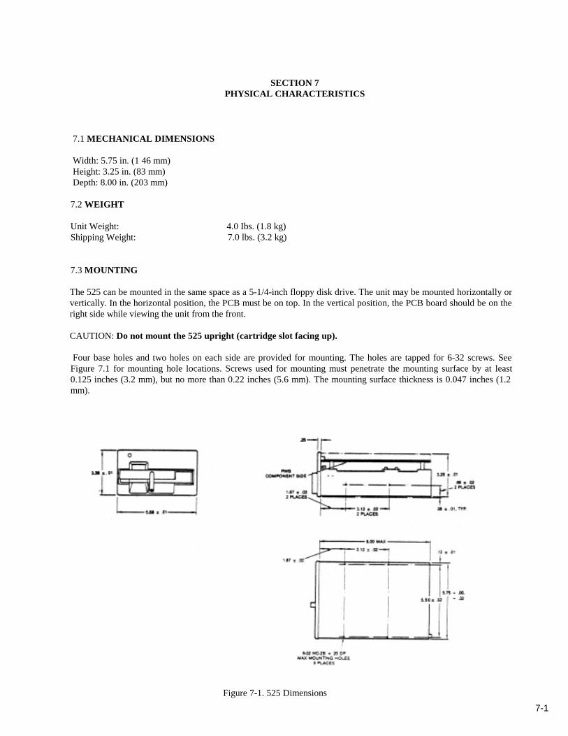
7.1 MECHANICAL DIMENSIONS
Width: 5.75 in. (1 46 mm)Height: 3.25 in. (83 mm)Depth: 8.00 in. (203 mm)
7.2 WEIGHT
Unit Weight: 4.0 Ibs. (1.8 kg)Shipping Weight: 7.0 lbs. (3.2 kg)
7.3 MOUNTING
The 525 can be mounted in the same space as a 5-1/4-inch floppy disk drive. The unit may be mounted horizontally orvertically. In the horizontal position, the PCB must be on top. In the vertical position, the PCB board should be on theright side while viewing the unit from the front.
CAUTION: Do not mount the 525 upright (cartridge slot facing up).
Four base holes and two holes on each side are provided for mounting. The holes are tapped for 6-32 screws. SeeFigure 7.1 for mounting hole locations. Screws used for mounting must penetrate the mounting surface by at least0.125 inches (3.2 mm), but no more than 0.22 inches (5.6 mm). The mounting surface thickness is 0.047 inches (1.2mm).
Figure 7-1. 525 Dimensions

8-1
SECTION 8ENVIRONMENTAL CHARACTERISTICS/POWER REQUIREM ENTS
8.1 TEMPERATUREOperational: 5 to 45°C, measured at cartridge base
(max. gradient of 1°C per minute)Non-Operational: -30 to 60°C
Temperature Cycling: No condensation shall result
8.2 HUMIDITYOperational: 20 to 80% relative humidity*
Non-Operational: 1 to 90% relative humidity**Wet bulb temperature 26° max., non-condensing
8.3 ALTITUDEOperational: Sea level to 10,000 ft (3,000 m)
Non-Operational: Same as OperationalShipping: Sea level to 49,000 ft (15,000 m)
8.4 VIBRATIONEquipment The unit shall withstand a peak acceleration of
Operational: 0.3g for the frequency range of 5-500 Hz alongeach orthogonal axis.
Equipment The unit shall withstand a peak acceleration ofNon-Operational: 0.3g for the frequency range of 5-500 Hz along
each orthogonal axis.
8.5 SHOCKThe equipment in a non-operational status shall not suffer damage or fail to operate according to specifications, whensubjected to a 30g shock.
8.6 AIR QUALITYThe unit will function in a normal office environment, i.e., up to 60 milligrams of 5-micron diameter dust particles per100 cubic feet of air.

8-2
8.7 ACOUSTICAL NOISE
Standby: InaudibleSteady Tape Motion: Less than 55 dba at a distance of 3.3 feet (1 m)
8.8 DC POWER
+5V ±5%, 0.8A max., 50 mV max. ripple (peak to peak)+12V ±5%, 1.8A nominal, 2.5A surge max. during cartridge acceleration (350 msduration). 100 mV max. ripple (peak to peak).
Source Impedance: 50 milliohms max.
8.9 HEAT DISSIPATION
25.6 Watts operational: 87 BTU/hr35.0 Watts surge (250 ms duration): 119 BTU/hr
8.10 COOLING
Dependent on individual mounting and type of operation, 15cf/min fan recommended for most applications.
9-1
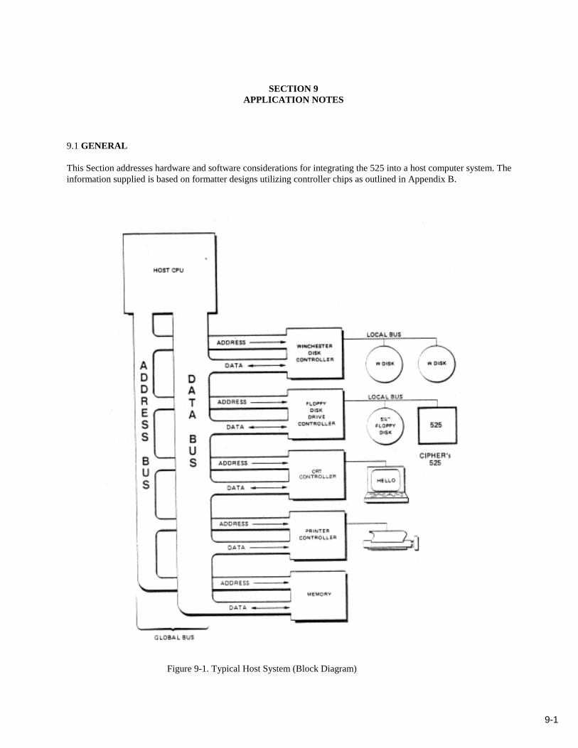
SECTION 9APPLICATION NOTES
9.1 GENERAL
This Section addresses hardware and software considerations for integrating the 525 into a host computer system. Theinformation supplied is based on formatter designs utilizing controller chips as outlined in Appendix B.
Figure 9-1. Typical Host System (Block Diagram)
9-2
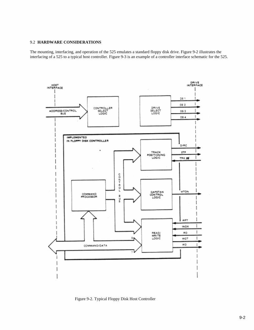
9.2 HARDWARE CONSIDERATIONS
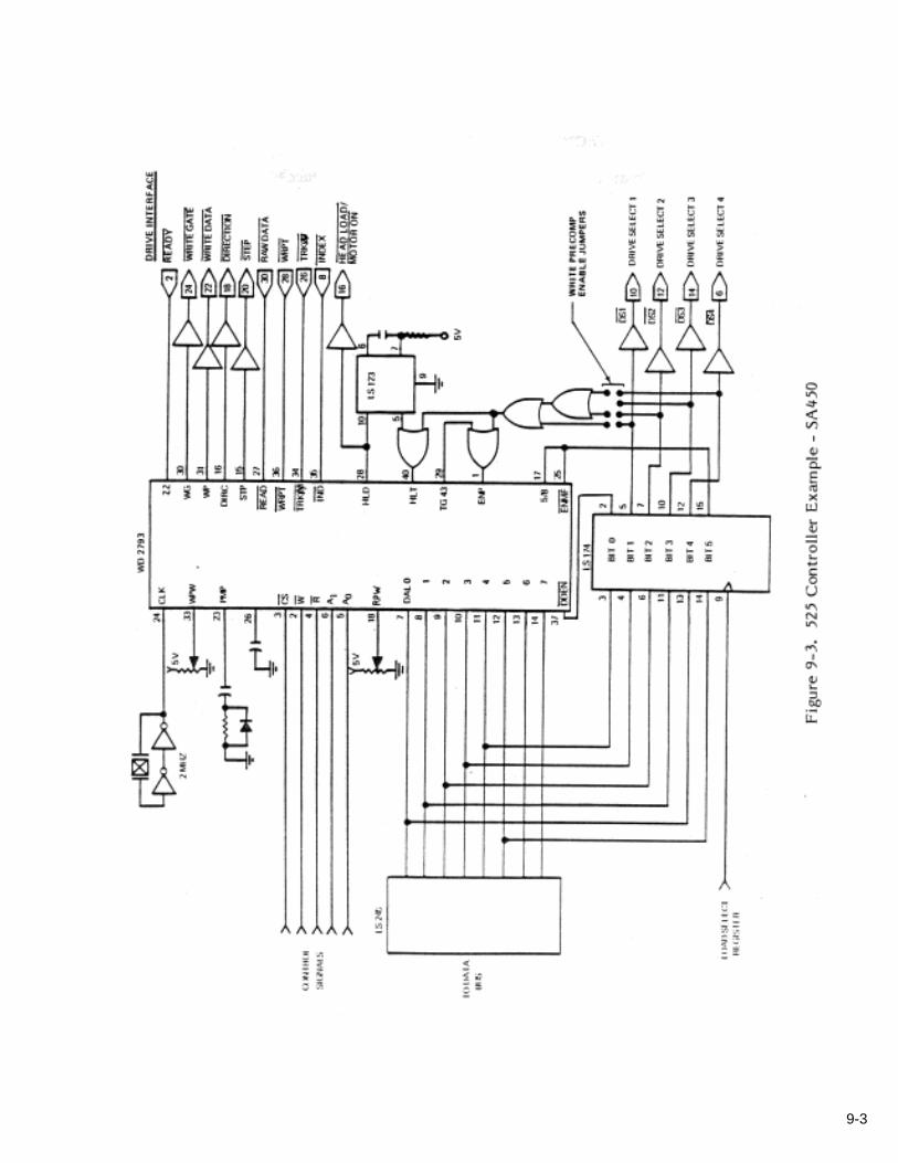
The mounting, interfacing, and operation of the 525 emulates a standard floppy disk drive. Figure 9-2 illustrates theinterfacing of a 525 to a typical host controller. Figure 9-3 is an example of a controller interface schematic for the 525.
Figure 9-2. Typical Floppy Disk Host Controller
9-3
9-4
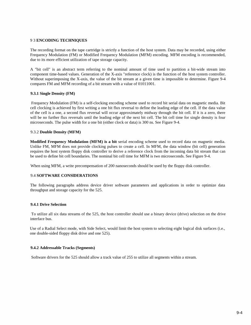
9 3 ENCODING TECHNIQUES
The recording format on the tape cartridge is strictly a function of the host system. Data may be recorded, using eitherFrequency Modulation (FM) or Modified Frequency Modulation (MFM) encoding. MFM encoding is recommended,due to its more efficient utilization of tape storage capacity.
A "bit cell" is an abstract term referring to the nominal amount of time used to partition a bit-wide stream intocomponent time-based values. Generation of the X-axis "reference clock) is the function of the host system controller.Without superimposing the X-axis, the value of the bit stream at a given time is impossible to determine. Figure 9-4compares FM and MFM recording of a bit stream with a value of 01011001.
9.3.1 Single Density (FM)
Frequency Modulation (FM) is a self-clocking encoding scheme used to record bit serial data on magnetic media. Bitcell clocking is achieved by first writing a one bit flux reversal to define the leading edge of the cell. If the data valueof the cell is a one, a second flux reversal will occur approximately midway through the bit cell. If it is a zero, therewill be no further flux reversals until the leading edge of the next bit cell. The bit cell time for single density is fourmicroseconds. The pulse width for a one bit (either clock or data) is 300 ns. See Figure 9-4.
9.3.2 Double Density (MFM)
Modified Frequency Modulation (MFM) is a bit serial encoding scheme used to record data on magnetic media.Unlike FM, MFM does not provide clocking pulses to create a cell. In MFM, the data window (bit cell) generationrequires the host system floppy disk controller to derive a reference clock from the incoming data bit stream that canbe used to define bit cell boundaries. The nominal bit cell time for MFM is two microseconds. See Figure 9-4.
When using MFM, a write precompensation of 200 nanoseconds should be used by the floppy disk controller.
9.4 SOFTWARE CONSlDERATIONS
The following paragraphs address device driver software parameters and applications in order to optimize datathroughput and storage capacity for the 525.
9.4.1 Drive Selection
To utilize all six data streams of the 525, the host controller should use a binary device (drive) selection on the driveinterface bus.
Use of a Radial Select mode, with Side Select, would limit the host system to selecting eight logical disk surfaces (i.e.,one double-sided floppy disk drive and one 525).
9.4.2 Addressable Tracks (Segments)
Software drivers for the 525 should allow a track value of 255 to utilize all segments within a stream.
9-5
Figure 9-4. FM vs. MFM Recording
9.4.3 Number Of Sectors
Software drivers for the 525 must utilize the appropriate number of sectors per segment. (See Paragraph 9.5.)
9.4.4 Stream Formatting
The operating system should format streams in consecutive pairs to reduce the time required for the verification pass.When Stream 2 is formatted after Stream 1, the controller can then start the verification pass for Stream 1 and thenStream 2. This way serpentine recording will not cause the loss of time required to recalibrate to Segment pt. Anotherway to accomplish the same result is to format all six streams prior to the start of the verification pass.
9.4.5 I/0 Buffering & Sector Interleaving
Multiple sector accessing should always be performed in a contiguous mode to avoid repositioning within segments.Therefore, there should be no sector interleaving.
Although sector interleaving is often used by systems integrators, it does lengthen the interblock time between sectorsthat is required by certain Disk Operating Systems (DOS) to relocate data. Another performance penalty occurs whenthe rate at which the DOS can accept data is exceeded, causing the system to wait one full disk rotation before beingable to retrieve the data written in the next consecutive sector. A similar penalty can occur when using the 525. It iscaused by a host system not being able to sustain a data rate of 49.1 Kbytes/sec with 512 byte sectors. The timerequired for each
9-6
reposition is 1.7 seconds. Disk users facing this problem address the issue by interleaving sectors by the same factor.However, sector interleaving on tape would force the 525 to perform constant repositions.
Fine tuning of the 525 to an Operating System can be accomplished by increasing the minimum gap size between sectorsto achieve the correct interblock Time. Using gap characters to compensate for the required Operating System InterblockTime eliminates the time penalty of a segment reposition at the expense of the users data capacity.
Adding one byte to the Inter-Record Gap (IRG) G3 (see Figure 9-5) increases this time by 16 us. Because the maximumavailable number of bytes per segment is 20,455 bytes, an increase of G3 could result in a smaller number of sectors persegment. Refer to Paragraph 9.5.1 for details.
9.4.6 Retension Pass
Tapes that have set idle, transported, handled excessively, or have been involved in more than 50 start/stop operations,should have a retension pass to ensure proper operation. Failure to do so may result in data error rates that areunacceptable. The 525 performs this function automatically when a tape is loaded into the device. The pass lasts forapproximately 90 seconds. Future 525s (January 1985) will have a short auto-retension pass built into the unit. This passwill also take place during a tape load, but will last for approximately 30 seconds.
Full retension passes can be performed under program control by seeking to segment 255. and followed by a return Seekto segment ~ Full retension is a function of host software and should be performed when soft errors increase to anunacceptable level due to excessive start/stop operations or repositions.
9 5 FORMATTING9.5.1 Format Description
In order to ensure interchangeability between drives and proper operation over the entire operating temperature range, itis requi red to have preambles and postambles (gaps) attached to each sector. The use of the standard IBM System 34format and MFM encoding is recommended. Formats deviating from the IBM standard must still comply with theminimum gap requirements specified for the IBM System 34 format. (See Figure 9-5.)
9-7
The formula for the maximum number of sectors per segment for a given sector size is:
Sectors Per Segment = SL – IPDF+OL+IGL
DF + OL + IGLSL = Segment length (fixed) = 20,455 bytesIP = Index Postamble = 146 bytes (IBM format)DF = Data Field = 256 or 512 or 1,024 bytesOL = 0verhead Length = 62 bytes (IBM format)IGL = Inter-record Gap Length G3 = 54 bytes for 256/512 byte Data Fields
84 bytes for 1,024 byte Data Fields
9-8

9-9
It is important to use controllers offering maximum versatility. Some floppy disk controllers allow only 15 sectors of512 bytes each to be formatted per segment. Others may not allow all 255 segments to be addressed. Limitations tothese parameters would significantly impact capacity and performance of a system.
9.5.2 Data Integrity
The 525 is a streaming device that has the ability to re-write individual sectors. Host operations should be designed torun this device in a streaming mode as much as possible.
System operations designed strictly for a start/stop operation will cause heat build up within the cartridge and the tapedevice. This heat has to be removed through external cooling (fan(s)). Failure to do so will lead to a rise intemperature that may exceed 45° at the cartridge base, and loss of data could result.
To ensure data integrity, the following steps should be taken by the host system:
1. Format each stream with the selected sector scheme. An all-ones pattern should be written in the user data field totest all bit cells within the user data area.
2. Run a verification pass against each formatted stream to test for dropout events which result in CRC errors. Anysector with CRC errors should be flagged in the Volume Table Of Contents (VTOC) to indicate a defectivesector. This prevents future use of defective sectors.
Each of the above passes takes approximately 90 seconds per stream to complete.
9.5.3 Format Operation
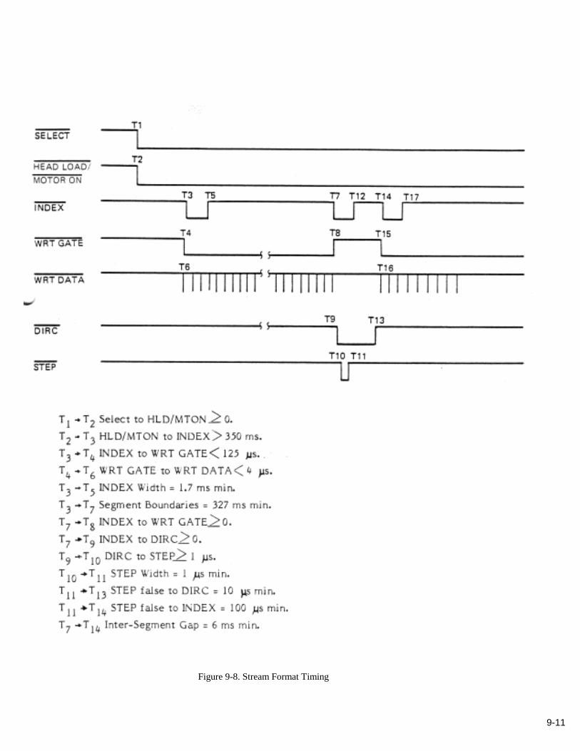
The 525 appears as a soft sectored floppy disk drive to the Floppy Disk Controller (FDC). Consequently, the format tobe recorded is determined by the FDC. During formatting, the FDC scans for an Index pulse on the drive interface.When detected, the FDC is to start writing the track format, beginning with the Index postamble gap, and followed bythe required numbers of sectors, including IDs. After the last sector, the FDC resumes writing the fill field (Indexpreamble gap) until another Index pulse occurs. Upon detection of the Index pulse, the FDC must stop the Writeoperation. The fill field allows the open loop writing process to be consistent with speed variations, and thereforeIndex timing, of the 525. The minimum time between Index pulses, while formatting, is 327 ms. Upon completion ofthe formatting operation, a verification pass should be run against each stream. (See Figures 9-6, 9-7 and 9-8.)
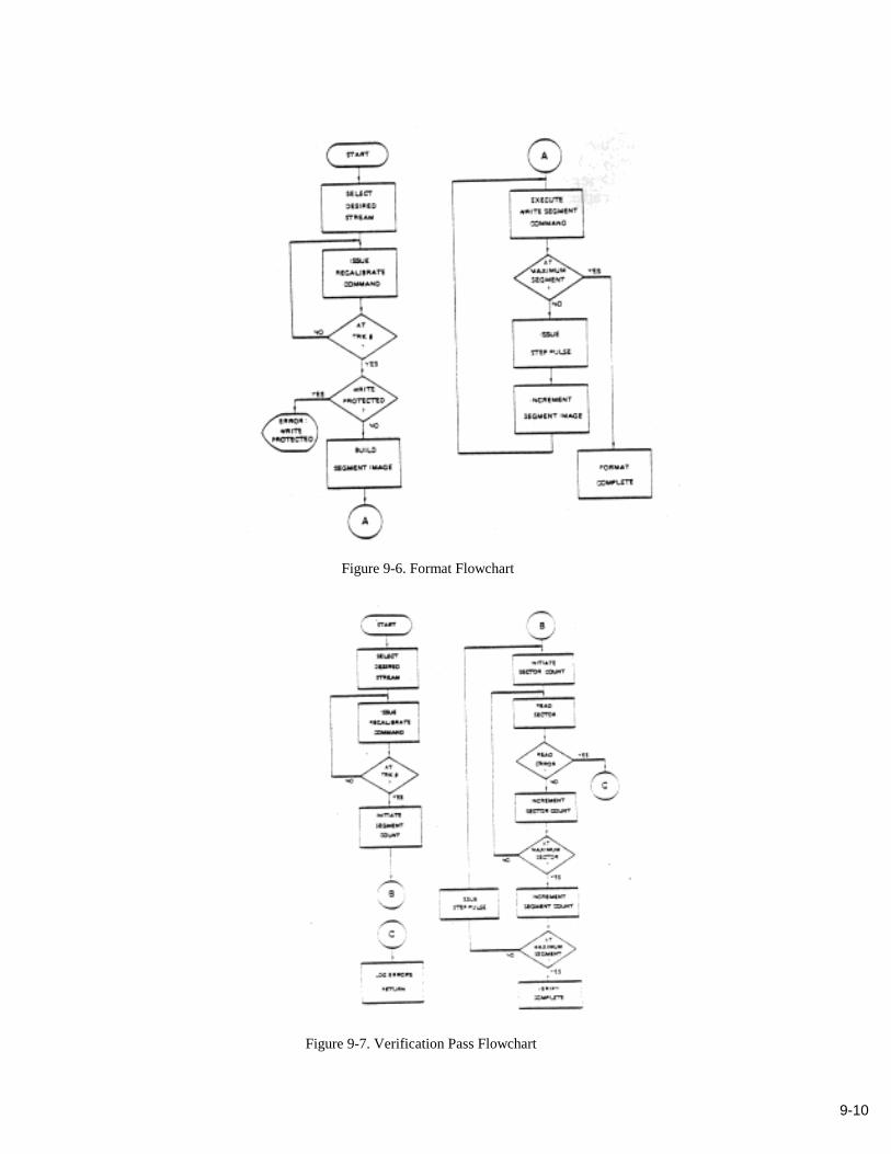
9-10
Figure 9-6. Format Flowchart
Figure 9-7. Verification Pass Flowchart
9-11
Figure 9-8. Stream Format Timing
9-12
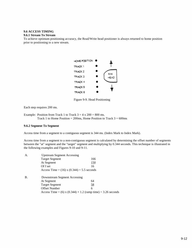
9.6 ACCESS TIMING9.6.1 Stream To StreamTo achieve optimum positioning accuracy, the Read/Write head positioner is always returned to home positionprior to positioning to a new stream.
Figure 9-9. Head Positioning
Each step requires 200 ms.
Example: Position from Track 1 to Track 3 = 4 x 200 = 800 ms.Track 1 to Home Position = 200ms, Home Position to Track 3 = 600ms
9.6.2 Segment To Segment
Access time from a segment to a contiguous segment is 344 ms. (Index Mark to Index Mark).
Access time from a segment to a non-contiguous segment is calculated by determining the offset number of segmentsbetween the "at" segment and the "target" segment and multiplying by 0.344 seconds. This technique is illustrated inthe following examples and Figures 9-10 and 9-11.
A. Upstream Segment AccessingTarget Segment 166At Segment 150Of f set 16Access Time = (16) x (0.344) = 5.5 seconds
B. Downstream Segment AccessingAt Segment 64Target Segment 58Offset Number 6Access Time = (6) x (0.344) + 1.2 (ramp time) = 3.26 seconds
9-13
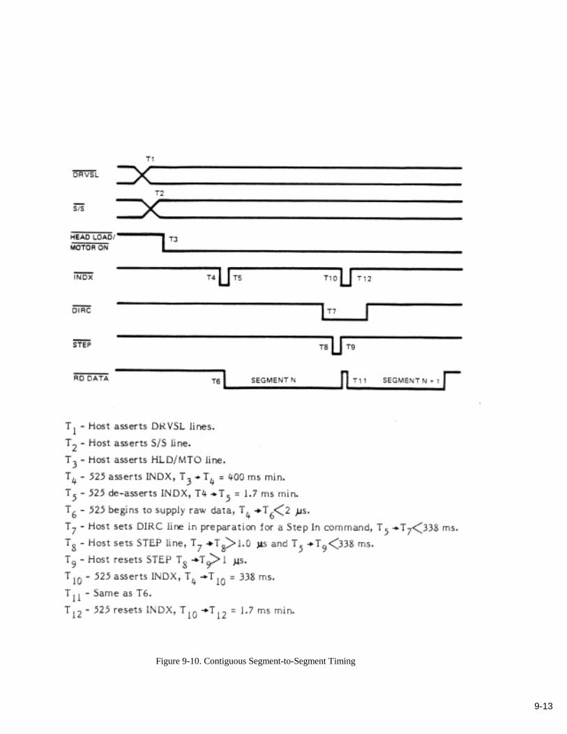
Figure 9-10. Contiguous Segment-to-Segment Timing
9-14
9.6.3 Read Reposition
Figure 9-11. Read Reposition Timing

A-1
APPENDIX ACONFIGURATION TABLES
A. 1 JUMPER OPTIONSJumpers W1 through W10 are used to configure the 525 as follows:
W1 - Stream selection jumper
W2 - Stream selection jumper
W3 - Stream selection jumper
W4 - In Use LED on when logical drive selected
W5 - In Use LED on when logical drive selected and Head Load line true and drive ready
W8 - When in, allows host generated signal to light front panel LED to indicate drive in use
W9 - Service aids configuration jumper
W10 - Service aids configuration jumper
A.2 STREAM SELECTION TABLES
Stream Selection is provided by the four Drive Select (DS 1-4) lines together with the Side Select line, as determinedby the configuration of jumpers W1, W2 and W3.
Option 1. Binary Select Using DS2 - DS4
A-2
Option 4. Radial Select Using DS1 - DS3 And Side Select
Option 3. Radial Select Using DS2 - DS4 And Side Select
Option 2. Binary Select Using DS1- DS3
A-3
Option 7. Binary Select Using DS3 - DS4 And Side Select
Option 6. Binary Select Using DS2 - DS3 And Side Select
Option 5. Binary Select Using DS1 - DS2 And Side Select

A-4
A.3 SERVICE AIDS
The on-board microprocessor can be utilized to perform basic service aid routines with the 525. The service aids areinitiated by applying ground jumpers W9 and W 10.
A.3.1 Continuous Forward /Reverse
With jumper W9 installed, inserting a cartridge causes the drive to do a normal retension pass and then start acontinuous forward/reverse cycling between BOT and EOT. Head position is changed at the end of each pass toequalize wear. This function is terminated by removing the jumper and the cartridge.
A.3.2 Stream Positioning - All Streams
With jumper W10 installed, inserting a cartridge causes the head to move to the home position. Then the head movesalternately between the home position and each stream position, first decrementing, then incrementing, with a onesecond delay at each position. The function is terminated by removing the jumper and the cartridge.
A.3.3 Stream Positioning - Stream 0 & 4
With jumper W10 installed, inserting a cartridge starts the routine outlined in Paragraph A.3.2. Subsequent insertionof W9 modifies the routine as follows: The head will alternate between the home position and Stream 4 only. The headwill remain two seconds at Stream 4, but turnaround without delay at the home position. Removal of W10 causes thehead to remain at Stream 4 until W10 is replaced. The function is terminated by removing the jumpers and thecartridge.
A.3.4 Cyclic Tape Motion
With jumpers W9 and W10 installed, inserting a cartridge causes the drive to do a normal retension pass and then starta cyclic run forward motion for approximately 500 milliseconds (ms), then run in reverse for approximately 125 ms.This cycle continues until EOT is reached. Then, the drive does a high speed reverse to BOT and starts the cycle over.This function is terminated by removing the jumpers and the cartridge.
B-1
APPENDIX BOPERATING PARAMETER CONSIDERATIONS
Integration of the 525 into a host floppy disk control system requires consideration of several specific operatingparameters. Parameter changes indicated in this Appendix reflect the use of either Western Digital 179X, 279X, orNEC 765 controller chips by the host system.
B.1 TIME OUTS
Two types of time outs may require adjustment for the 525.
The first time out is sometimes referred to as the "dead man" timer. This timer is used by the host system to test for acatastrophic device failure. Common implementation of this timer is to start its count when the drive is first accessed,and halt it with the Index pulse resumed by the drive. Because this timer is external to both types of controller chips, itmay become a software consideration for the host system. The nominal time for the 525 to generate an Index pulse is1.7 seconds from the time that the motion signal (Motor On or Head Load) is asserted. Any system time out shorterthan 1.7 seconds should be adjusted to reflect this parameter.
The second type of time outs are those internal to a specific floppy disk controller chip. These time outs are eitherspecified as part of commands (WD), or as part of a Specify Command (NEC), used to set up the controller prior to anoperation.
* The WD controller chips keep the head loaded for 15 "revolutions" (15 Index pulses) after the last command. Toavoid constant repositioning during this time, a Null Seek command should be issued at the completion of alltape movement operations. This is accomplished by Seeking the current segment with the HLD bit turned off inthe Seek command.
B.2 READ AFTER WRITE
The normal Read-After-Write operation for a floppy disk drive must be modified to achieve optimum performancewith the 525. Read verification following a format pass should be performed in a streaming mode. System integratorsshould modify their format routine to format adjacent streams in pairs (i.e., 1 + 2, 3 + 4, 5 +6) to eliminate the deadtime caused by recalibrating to logical Track 00 (Segment 0). The read verification following the format pass shouldbe performed in the same manner.
B-2
B.3 REINSTRUCT TIMlNG
The most critical timing for the 525 is in the format operation. Following the termination of a Write track operation byan Index pulse from the 525, the host controller has six milliseconds in which to give the drive a Step pulse to avoid areposition. It is recommended that when the controller completes the Write Track command, the host system shouldimmediately initiate a Step command. Following the Step command the host should then up-date the "Track ImageBuffer" (Western Digital) or the "Track Sector List" (NEC 765) in preparation for the next segment format operation.To ensure streaming operations when editing sectors or segments following formatting, the host system must performall Step In or Step Out type functions with the HLD bit turned on and the Verify bit (WD only) turned off.
B.4 SECTORS/SEGMENT COUNTS
In order to utilize the full capacity of the 525, the following parameters in the device driver software and formatroutine should be modified:
• Number of Segments/Stream (equivalent to Tracks/FD surface)
• Number of Sectors/Segment (equivalent to Sectors/FD track)
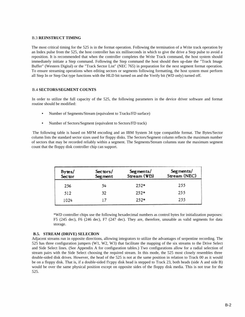
The following table is based on MFM encoding and an IBM System 34 type compatible format. The Bytes/Sectorcolumn lists the standard sector sizes used for floppy disks. The Sectors/Segment column reflects the maximum numberof sectors that may be recorded reliably within a segment. The Segments/Stream columns state the maximum segmentcount that the floppy disk controller chip can support.
*WD controller chips use the following hexadecimal numbers as control bytes for initialization purposes:F5 (245 dec), F6 (246 dec), F7 (247 dec). They are, therefore, unusable as valid segments for datastorage.
B.5. STREAM (DRIVE) SELECllONAdjacent streams run in opposite directions, allowing integrators to utilize the advantages of serpentine recording. The525 has three configuration jumpers (W1, W2, W3) that facilitate the mapping of the six streams to the Drive Selectand Side Select lines. (See Appendix A for configuration tables.) Two configurations allow for a radial selection ofstream pairs with the Side Select choosing the required stream. In this mode, the 525 most closely resembles threedouble-sided disk drives. However, the head of the 525 is not at the same position in relation to Track 00 as it wouldbe on a floppy disk. That is, if a double-sided f!cppy disk head is stepped to Track 23, both heads (side A and side B)would be over the same physical position except on opposite sides of the floppy disk media. This is not true for the525.

Bulletin No. 02-312-1184-2K
10101 Old Grove RoadP.O. Box 85170San Diego, CA 92138Te lephone (619) 578-9100TWX 910-335-1251
NORTH AMERICAEastem Region255 Ballardvale St.Wilmington, MA 01887Telephone: 617/658-7941TWX: 710-393-0830621 Shrewsbury AvenueSuite AShrewsbury, NJ 07701Telephone: 201/741-2755Central Region12860 Hillcrest RoadSuite 201Dallas, TX 75230Telephone: 214/458-1853TWX: 910-860-57742501 E. Commercial Blvd.Ft. Lauderdale, FL 33308Telephone: 305/772-2900TWX: 510-955-4162650 East Devon AvenueSuite 180Itasca, IL 60143Telephone: 312/250-0100TWX: 9 10-651-4730
Western Region4000 Westerly PlaceSuite 285Newport Beach, CA 92660Telephone: 714/833-8751TWX: 9 10-333-09151737 North First Street,Suite 505San Jose, CA 95112Telephone: 408/298-6252TWX: 910-333-09082659 Townsgate RoadSuite 101Westlake Village, CA 91361Telephone: 805/495-8844
EUROPEUnited KingdomCipher Data Products (UK) Ltd.Compton Place, Surrey AvenueCamberley, SurreyEngland GU15 3DXTelephone: 0276-682912Telex: 858329FranceCipher Data Products SARL2/4 Avenue de la CerisaiePlatanes 30594266 Fresnes Cedex, FranceTelephone: 331 668 8787Telex: 0022 203935West GermanyCipher Data Products GmbHBenzstrasse 30D-8039 Puchheim/MunichWest GermanyTelephone: 49 89 8G7001Telex: 003 521 4094
CIPHER SALES