Embed Size (px)
Citation preview

Product Data SheetPS-001885, Rev. F
August 2016
Micro Motion® Model 5700 Transmitters with MVD™ TechnologyMicro Motion® Model 5700 transmitters with MVD™ technology deliver powerful features that make managing your process easier.
Repeatable, reliable, accurate measurements Faster processing speed delivers the best response even in
the most challenging applications such as meter proving, filling & dosing, and batching
Smart Meter Verification provides you with the confidence you need in your meter performance
Zero verification confirms the calibration and indicates when it’s time to re-zero the meter
Approved for custody transfer and certified for SIL2 and SIL3, which provides measurement confidence and reliability
A window into your process Easy access to detailed measurement history gives you
valuable insight into your process for better troubleshooting and optimization
Real-time indication of multi-phase flow events allow for greater process control
High-accuracy density measurement reduces or eliminates waste in your process while the embedded historian records upsets and process deviations.
Productivity through simplified solutions Designed to minimize the time and expertise needed to install and operate the flowmeter
Up to five fully configurable I/O channels that can be easily upgraded with changing needs
Ethernet version includes multiple protocols on dual channels, plus a configurable I/O channel
FOUNDATIONTM Fieldbus version includes IEC-61158-2 FOUNDATION Fieldbus output, a fixed mA output channel, and a configurable frequency / discrete output channel.
Offline configuration and auditing through new file shuttling capability
2 www.micromotion.com
Model 5700 Transmitters August 2016
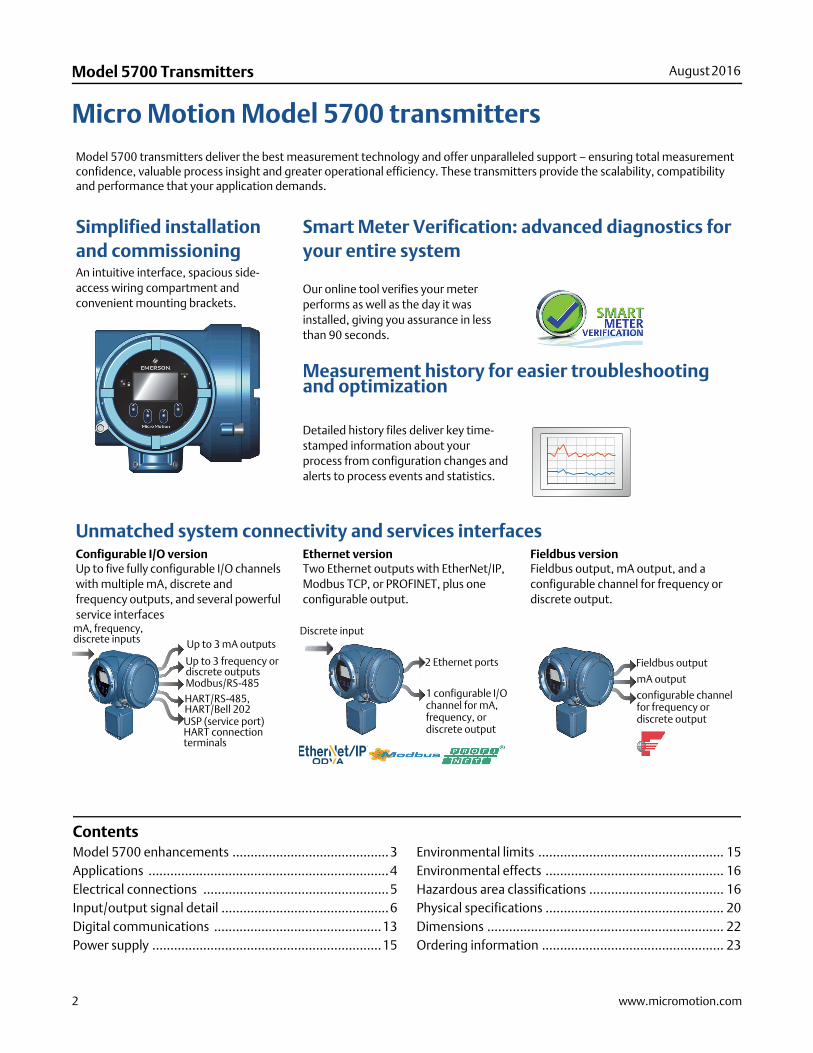
Micro Motion Model 5700 transmittersModel 5700 transmitters deliver the best measurement technology and offer unparalleled support – ensuring total measurement confidence, valuable process insight and greater operational efficiency. These transmitters provide the scalability, compatibility and performance that your application demands.
Simplified installation and commissioningAn intuitive interface, spacious side-access wiring compartment and convenient mounting brackets.
Smart Meter Verification: advanced diagnostics for your entire system
Our online tool verifies your meter performs as well as the day it was installed, giving you assurance in less than 90 seconds.
Measurement history for easier troubleshooting and optimization
Detailed history files deliver key time-stamped information about your process from configuration changes and alerts to process events and statistics.
Unmatched system connectivity and services interfacesConfigurable I/O versionUp to five fully configurable I/O channels with multiple mA, discrete and frequency outputs, and several powerful service interfaces
Ethernet versionTwo Ethernet outputs with EtherNet/IP, Modbus TCP, or PROFINET, plus one configurable output.
Fieldbus versionFieldbus output, mA output, and a configurable channel for frequency or discrete output.
Up to 3 mA outputs
Up to 3 frequency or discrete outputs
mA, frequency, discrete inputs
Modbus/RS-485HART/RS-485, HART/Bell 202USP (service port)HART connection terminals
2 Ethernet ports
1 configurable I/O channel for mA, frequency, or discrete output
Discrete input
Fieldbus output
mA output
configurable channel for frequency or discrete output
Contents Model 5700 enhancements ...........................................3Applications ..................................................................4Electrical connections ...................................................5Input/output signal detail ..............................................6Digital communications ..............................................13Power supply ...............................................................15
Environmental limits ................................................... 15Environmental effects ................................................. 16Hazardous area classifications ..................................... 16Physical specifications ................................................. 20Dimensions ................................................................. 22Ordering information .................................................. 23
www.micromotion.com 3
August 2016 Model 5700 Transmitters
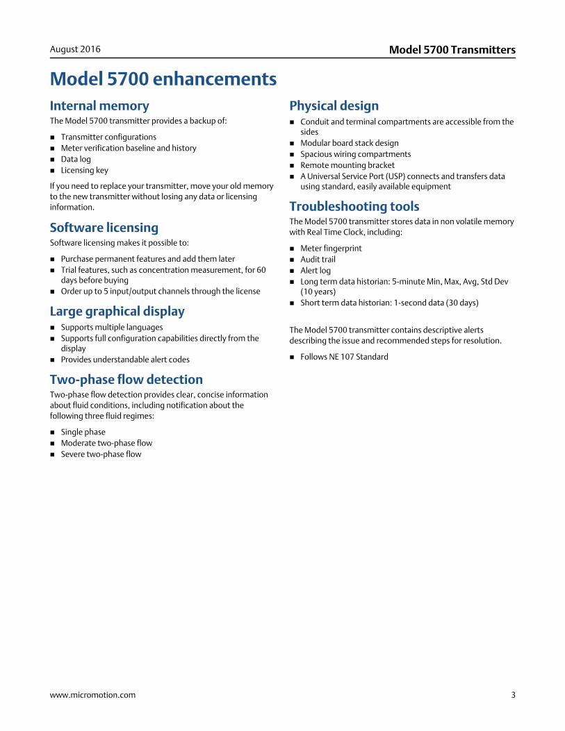
Model 5700 enhancementsInternal memoryThe Model 5700 transmitter provides a backup of:
Transmitter configurations Meter verification baseline and history Data log Licensing key
If you need to replace your transmitter, move your old memory to the new transmitter without losing any data or licensing information.
Software licensingSoftware licensing makes it possible to:
Purchase permanent features and add them later Trial features, such as concentration measurement, for 60
days before buying Order up to 5 input/output channels through the license
Large graphical display Supports multiple languages Supports full configuration capabilities directly from the
display Provides understandable alert codes
Two-phase flow detectionTwo-phase flow detection provides clear, concise information about fluid conditions, including notification about the following three fluid regimes:
Single phase Moderate two-phase flow Severe two-phase flow
Physical design Conduit and terminal compartments are accessible from the
sides Modular board stack design Spacious wiring compartments Remote mounting bracket A Universal Service Port (USP) connects and transfers data
using standard, easily available equipment
Troubleshooting toolsThe Model 5700 transmitter stores data in non volatile memory with Real Time Clock, including:
Meter fingerprint Audit trail Alert log Long term data historian: 5-minute Min, Max, Avg, Std Dev
(10 years) Short term data historian: 1-second data (30 days)
The Model 5700 transmitter contains descriptive alerts describing the issue and recommended steps for resolution.
Follows NE 107 Standard
4 www.micromotion.com
Model 5700 Transmitters August 2016
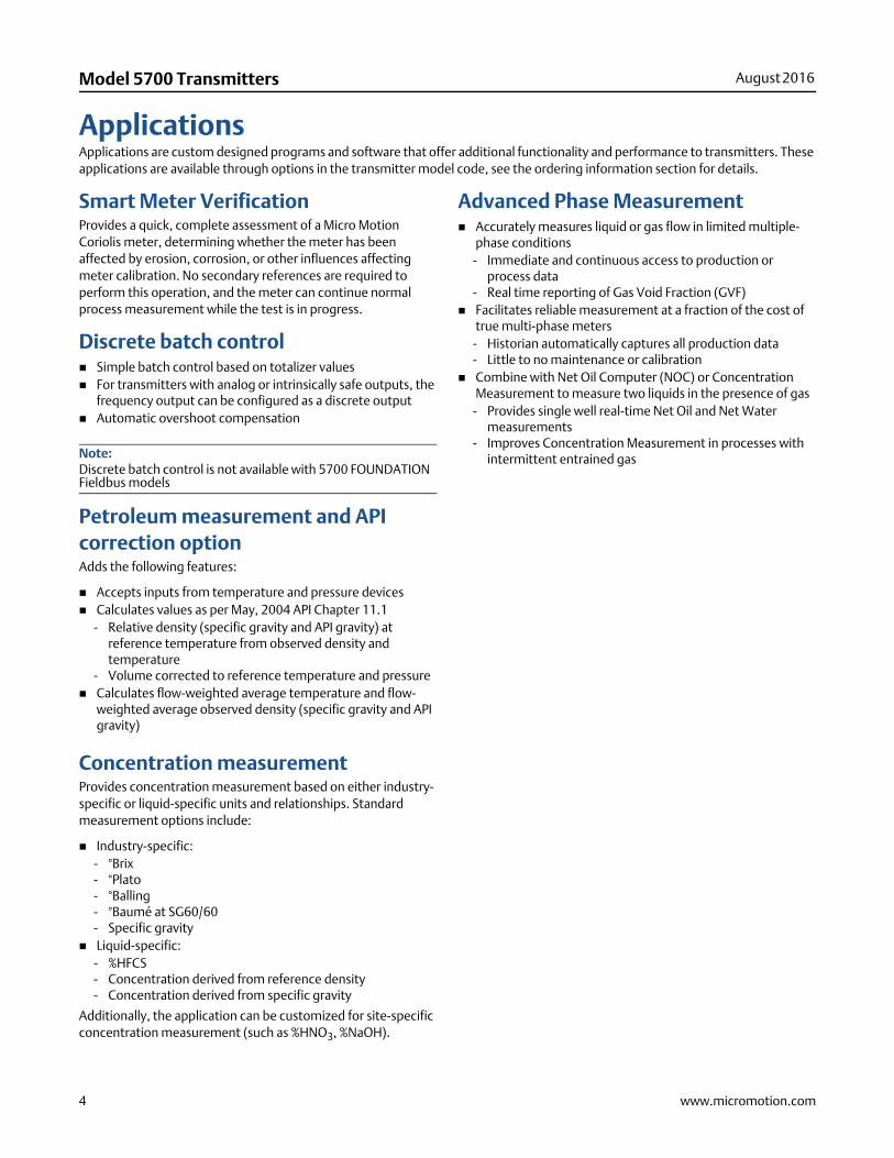
ApplicationsApplications are custom designed programs and software that offer additional functionality and performance to transmitters. These applications are available through options in the transmitter model code, see the ordering information section for details.
Smart Meter VerificationProvides a quick, complete assessment of a Micro Motion Coriolis meter, determining whether the meter has been affected by erosion, corrosion, or other influences affecting meter calibration. No secondary references are required to perform this operation, and the meter can continue normal process measurement while the test is in progress.
Discrete batch control Simple batch control based on totalizer values For transmitters with analog or intrinsically safe outputs, the
frequency output can be configured as a discrete output Automatic overshoot compensation
Petroleum measurement and API correction optionAdds the following features:
Accepts inputs from temperature and pressure devices Calculates values as per May, 2004 API Chapter 11.1
- Relative density (specific gravity and API gravity) at reference temperature from observed density and temperature
- Volume corrected to reference temperature and pressure Calculates flow-weighted average temperature and flow-
weighted average observed density (specific gravity and API gravity)
Concentration measurementProvides concentration measurement based on either industry-specific or liquid-specific units and relationships. Standard measurement options include:
Industry-specific:- °Brix- °Plato- °Balling- °Baumé at SG60/60- Specific gravity
Liquid-specific:- %HFCS- Concentration derived from reference density- Concentration derived from specific gravity
Additionally, the application can be customized for site-specific concentration measurement (such as %HNO3, %NaOH).
Advanced Phase Measurement Accurately measures liquid or gas flow in limited multiple-
phase conditions- Immediate and continuous access to production or
process data- Real time reporting of Gas Void Fraction (GVF)
Facilitates reliable measurement at a fraction of the cost of true multi-phase meters
- Historian automatically captures all production data- Little to no maintenance or calibration
Combine with Net Oil Computer (NOC) or Concentration Measurement to measure two liquids in the presence of gas
- Provides single well real-time Net Oil and Net Water measurements
- Improves Concentration Measurement in processes with intermittent entrained gasNote:
Discrete batch control is not available with 5700 FOUNDATION Fieldbus models
www.micromotion.com 5
August 2016 Model 5700 Transmitters
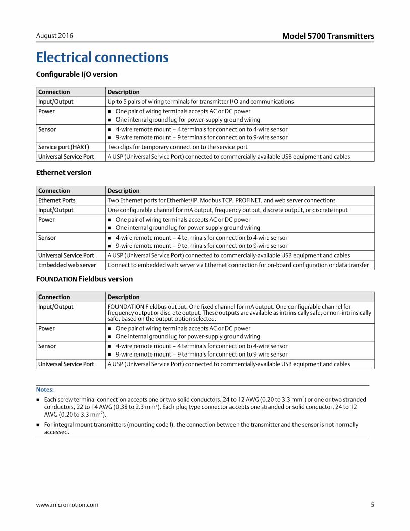
Electrical connectionsConfigurable I/O version
Ethernet version
FOUNDATION Fieldbus version
Connection Description
Input/Output Up to 5 pairs of wiring terminals for transmitter I/O and communications
Power One pair of wiring terminals accepts AC or DC power One internal ground lug for power-supply ground wiring
Sensor 4-wire remote mount – 4 terminals for connection to 4-wire sensor 9-wire remote mount – 9 terminals for connection to 9-wire sensor
Service port (HART) Two clips for temporary connection to the service port
Universal Service Port A USP (Universal Service Port) connected to commercially-available USB equipment and cables
Connection Description
Ethernet Ports Two Ethernet ports for EtherNet/IP, Modbus TCP, PROFINET, and web server connections
Input/Output One configurable channel for mA output, frequency output, discrete output, or discrete input
Power One pair of wiring terminals accepts AC or DC power One internal ground lug for power-supply ground wiring
Sensor 4-wire remote mount – 4 terminals for connection to 4-wire sensor 9-wire remote mount – 9 terminals for connection to 9-wire sensor
Universal Service Port A USP (Universal Service Port) connected to commercially-available USB equipment and cables
Embedded web server Connect to embedded web server via Ethernet connection for on-board configuration or data transfer
Connection Description
Input/Output FOUNDATION Fieldbus output, One fixed channel for mA output. One configurable channel for frequency output or discrete output. These outputs are available as intrinsically safe, or non-intrinsically safe, based on the output option selected.
Power One pair of wiring terminals accepts AC or DC power One internal ground lug for power-supply ground wiring
Sensor 4-wire remote mount – 4 terminals for connection to 4-wire sensor 9-wire remote mount – 9 terminals for connection to 9-wire sensor
Universal Service Port A USP (Universal Service Port) connected to commercially-available USB equipment and cables
Notes:
Each screw terminal connection accepts one or two solid conductors, 24 to 12 AWG (0.20 to 3.3 mm2) or one or two stranded conductors, 22 to 14 AWG (0.38 to 2.3 mm2). Each plug type connector accepts one stranded or solid conductor, 24 to 12 AWG (0.20 to 3.3 mm2).
For integral mount transmitters (mounting code I), the connection between the transmitter and the sensor is not normally accessed.
6 www.micromotion.com
Model 5700 Transmitters August 2016
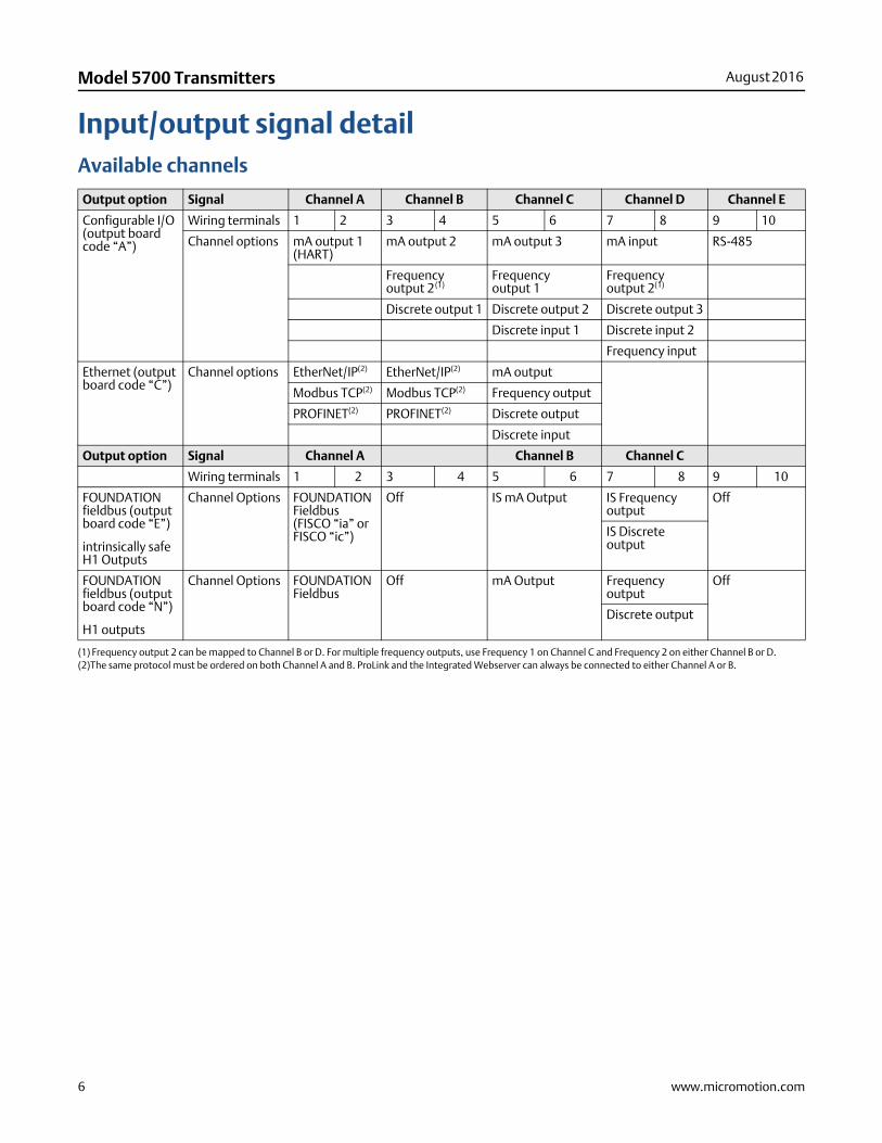
Input/output signal detailAvailable channels
Output option Signal Channel A Channel B Channel C Channel D Channel E
Configurable I/O (output board code “A”)
Wiring terminals 1 2 3 4 5 6 7 8 9 10
Channel options mA output 1 (HART)
mA output 2 mA output 3 mA input RS-485
Frequency output 2(1)
(1) Frequency output 2 can be mapped to Channel B or D. For multiple frequency outputs, use Frequency 1 on Channel C and Frequency 2 on either Channel B or D.(2)The same protocol must be ordered on both Channel A and B. ProLink and the Integrated Webserver can always be connected to either Channel A or B.
Frequency output 1
Frequency output 2(1)
Discrete output 1 Discrete output 2 Discrete output 3
Discrete input 1 Discrete input 2
Frequency input
Ethernet (output board code “C”)
Channel options EtherNet/IP(2) EtherNet/IP(2) mA output
Modbus TCP(2) Modbus TCP(2) Frequency output
PROFINET(2) PROFINET(2) Discrete output
Discrete input
Output option Signal Channel A Channel B Channel C
Wiring terminals 1 2 3 4 5 6 7 8 9 10
FOUNDATION fieldbus (output board code “E”)
intrinsically safe H1 Outputs
Channel Options FOUNDATION Fieldbus (FISCO “ia” or FISCO “ic”)
Off IS mA Output IS Frequency output
Off
IS Discrete output
FOUNDATION fieldbus (output board code “N”)
H1 outputs
Channel Options FOUNDATION Fieldbus
Off mA Output Frequency output
Off
Discrete output
www.micromotion.com 7
August 2016 Model 5700 Transmitters
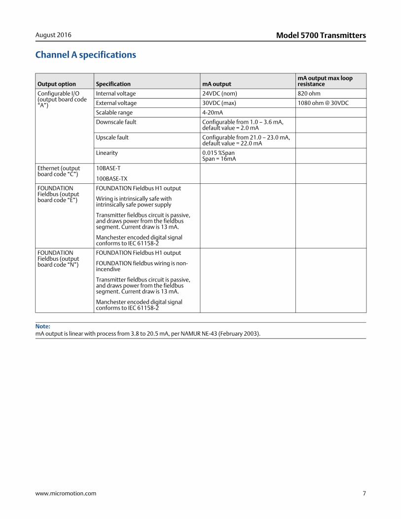
Channel A specifications
Output option Specification mA outputmA output max loop resistance
Configurable I/O (output board code “A”)
Internal voltage 24VDC (nom) 820 ohm
External voltage 30VDC (max) 1080 ohm @ 30VDC
Scalable range 4-20mA
Downscale fault Configurable from 1.0 – 3.6 mA, default value = 2.0 mA
Upscale fault Configurable from 21.0 – 23.0 mA, default value = 22.0 mA
Linearity 0.015 %SpanSpan = 16mA
Ethernet (output board code “C”)
10BASE-T
100BASE-TX
FOUNDATION Fieldbus (output board code “E”)
FOUNDATION Fieldbus H1 output
Wiring is intrinsically safe with intrinsically safe power supply
Transmitter fieldbus circuit is passive, and draws power from the fieldbus segment. Current draw is 13 mA.
Manchester encoded digital signal conforms to IEC 61158-2
FOUNDATION Fieldbus (output board code “N”)
FOUNDATION Fieldbus H1 output
FOUNDATION fieldbus wiring is non-incendive
Transmitter fieldbus circuit is passive, and draws power from the fieldbus segment. Current draw is 13 mA.
Manchester encoded digital signal conforms to IEC 61158-2
Note:mA output is linear with process from 3.8 to 20.5 mA, per NAMUR NE-43 (February 2003).
8 www.micromotion.com
Model 5700 Transmitters August 2016
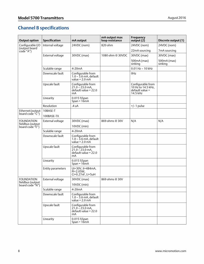
Channel B specifications
Output option Specification mA outputmA output max loop resistance
Frequency output (2) Discrete output (1)
Configurable I/O (output board code “A”)
Internal voltage 24VDC (nom) 820 ohm 24VDC (nom)
22mA sourcing
24VDC (nom)
7mA sourcing
External voltage 30VDC (max) 1080 ohm @ 30VDC 30VDC (max)
500mA (max) sinking
30VDC (max)
500mA (max) sinking
Scalable range 4-20mA 0.01 Hz – 10 kHz
Downscale fault Configurable from 1.0 – 3.6 mA, default value = 2.0 mA
0Hz
Upscale fault Configurable from 21.0 – 23.0 mA, default value = 22.0 mA
Configurable from 10 Hz to 14.5 kHz, default value = 14.5 kHz
Linearity 0.015 %SpanSpan = 16mA
Resolution .4 uA +/- 1 pulse
Ethernet (output board code “C”)
10BASE-T
100BASE-TX
FOUNDATION fieldbus (output board code “E”)
External voltage 30VDC (max)
10VDC (min)
869 ohms @ 30V N/A N/A
Scalable range 4-20mA
Downscale fault Configurable from 1.0 – 3.6 mA, default value = 2.0 mA
Upscale fault Configurable from 21.0 – 23.0 mA, default value = 22.0 mA
Linearity 0.015 %SpanSpan = 16mA
Entity parameters Ui=30V, Ii=484mA, Pi=2.05W, Ci=0.27nF, Li=5uH
FOUNDATION fieldbus (output board code “N”)
External voltage 30VDC (max)
10VDC (min)
869 ohms @ 30V
Scalable range 4-20mA
Downscale fault Configurable from 1.0 – 3.6 mA, default value = 2.0 mA
Upscale fault Configurable from 21.0 – 23.0 mA, default value = 22.0 mA
Linearity 0.015 %SpanSpan = 16mA
www.micromotion.com 9
August 2016 Model 5700 Transmitters
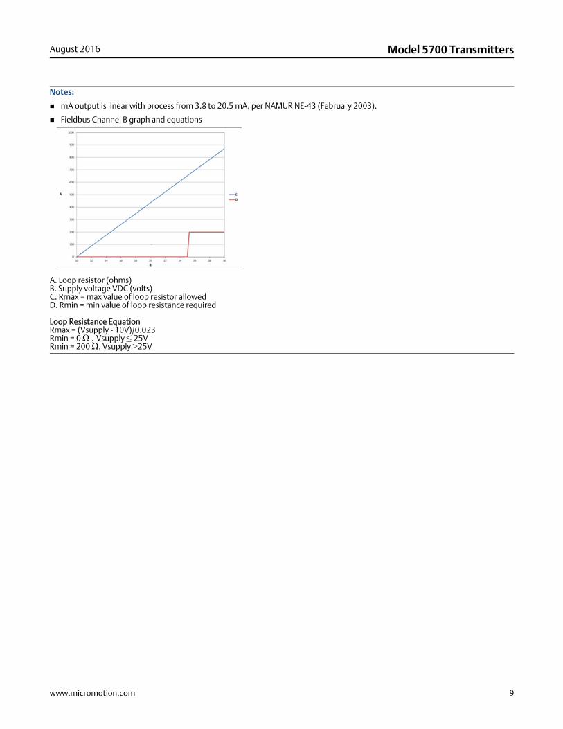
Notes:
mA output is linear with process from 3.8 to 20.5 mA, per NAMUR NE-43 (February 2003).
Fieldbus Channel B graph and equations
A. Loop resistor (ohms)B. Supply voltage VDC (volts)C. Rmax = max value of loop resistor allowedD. Rmin = min value of loop resistance required
Loop Resistance EquationRmax = (Vsupply - 10V)/0.023Rmin = 0 Ω , Vsupply ≤ 25VRmin = 200 Ω, Vsupply >25V
10 www.micromotion.com
Model 5700 Transmitters August 2016
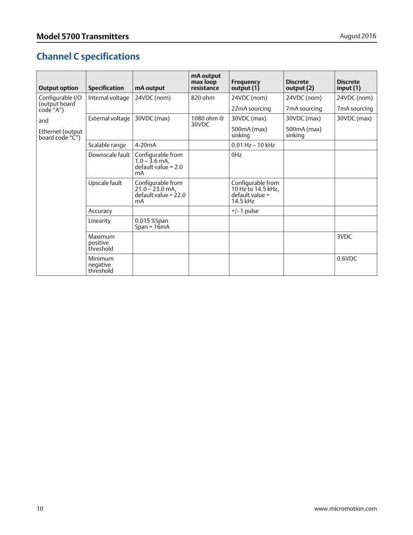
Channel C specifications
Output option Specification mA output
mA output max loop resistance
Frequency output (1)
Discrete output (2)
Discrete input (1)
Configurable I/O (output board code “A”)
and
Ethernet (output board code “C”)
Internal voltage 24VDC (nom) 820 ohm 24VDC (nom)
22mA sourcing
24VDC (nom)
7mA sourcing
24VDC (nom)
7mA sourcing
External voltage 30VDC (max) 1080 ohm @ 30VDC
30VDC (max)
500mA (max) sinking
30VDC (max)
500mA (max) sinking
30VDC (max)
Scalable range 4-20mA 0.01 Hz – 10 kHz
Downscale fault Configurable from 1.0 – 3.6 mA, default value = 2.0 mA
0Hz
Upscale fault Configurable from 21.0 – 23.0 mA, default value = 22.0 mA
Configurable from 10 Hz to 14.5 kHz, default value = 14.5 kHz
Accuracy +/- 1 pulse
Linearity 0.015 %SpanSpan = 16mA
Maximum positive threshold
3VDC
Minimum negative threshold
0.6VDC
www.micromotion.com 11
August 2016 Model 5700 Transmitters
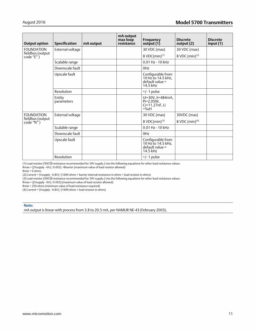
FOUNDATION fieldbus (output code “E” )
External voltage 30 VDC (max)
8 VDC(min)(1)
30 VDC (max)
8 VDC (min)(2)
Scalable range 0.01 Hz - 10 kHz
Downscale fault 0Hz
Upscale fault Configurable from 10 Hz to 14.5 kHz, default value = 14.5 kHz
Resolution +/- 1 pulse
Entity parameters
Ui=30V, Ii=484mA, Pi=2.05W, Ci=11.27nF, Li =5uH
FOUNDATION fieldbus (output code “N” )
External voltage 30 VDC (max)
8 VDC(min)(3)
30VDC (max)
8 VDC (min)(4)
Scalable range 0.01 Hz - 10 kHz
Downscale fault 0Hz
Upscale fault Configurable from 10 Hz to 14.5 kHz, default value = 14.5 kHz
Resolution +/- 1 pulse
(1) Load resistor (500 Ω resistance recommended for 24V supply.) Use the following equations for other load resistance values:Rmax = [(Vsupply - 6V) / 0.003] - Rbarrier (maximum value of load resistor allowed)Rmin = 0 ohms(2) Current = (Vsupply - 0.8V) / (1690 ohms + barrier internal resistance in ohms + load resistor in ohms)(3) Load resistor (500 Ω resistance recommended for 24V supply.) Use the following equations for other load resistance values:Rmax = [(Vsupply - 6V) / 0.003] (maximum value of load resistor allowed)Rmin = 250 ohms (minimum value of load resistance required)(4) Current = (Vsupply - 0.8V) / (1690 ohms + load resistor in ohms)
Note:mA output is linear with process from 3.8 to 20.5 mA, per NAMUR NE-43 (February 2003).
Output option Specification mA output
mA output max loop resistance
Frequency output (1)
Discrete output (2)
Discrete input (1)
12 www.micromotion.com
Model 5700 Transmitters August 2016
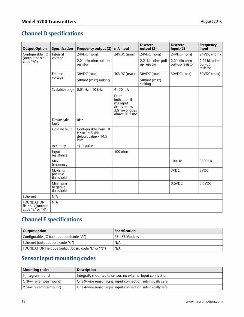
Channel D specifications
Channel E specifications
Sensor input mounting codes
Output Option Specification Frequency output (2) mA inputDiscrete output (3)
Discrete input (2)
Frequency input
Configurable I/O (output board code “A”)
Internal voltage
24VDC (nom)
2.21 kilo ohm pull-up resistor
24VDC (nom) 24VDC (nom)
2.21kilo ohm pull-up resistor
24VDC (nom)
2.21 kilo ohm pull-up resistor
24VDC (nom)
2.21 kilo ohm pull-up resistor
External voltage
30VDC (max)
500mA (max) sinking
30VDC (max) 30VDC (max)
500mA (max) sinking
30VDC (max) 30VDC (max)
Scalable range 0.01 Hz – 10 kHz 4 - 20 mA
Fault indication if mA input drops below 3.8 mA or goes above 20.5 mA
Downscale fault
0Hz
Upscale fault Configurable from 10 Hz to 14.5 kHz, default value = 14.5 kHz
Accuracy +/- 1 pulse
Input resistance
100 ohm
Max frequency
100 Hz 3500 Hz
Maximum positive threshold
3VDC 3VDC
Minimum negative threshold
0.6VDC 0.6VDC
Ethernet N/A
FOUNDATION fieldbus (output code “E” or “N”)
N/A
Output option Specification
Configurable I/O (output board code “A”) RS-485 Modbus
Ethernet (output board code “C”) N/A
FOUNDATION Fieldbus (output board code “E” or “N”) N/A
Mounting codes Description
I (integral mount) Integrally mounted to sensor, no external input connection
C (9-wire remote mount) One 9-wire sensor signal input connection, intrinsically safe
R (4-wire remote mount) One 4-wire sensor signal input connection, intrinsically safe
www.micromotion.com 13
August 2016 Model 5700 Transmitters
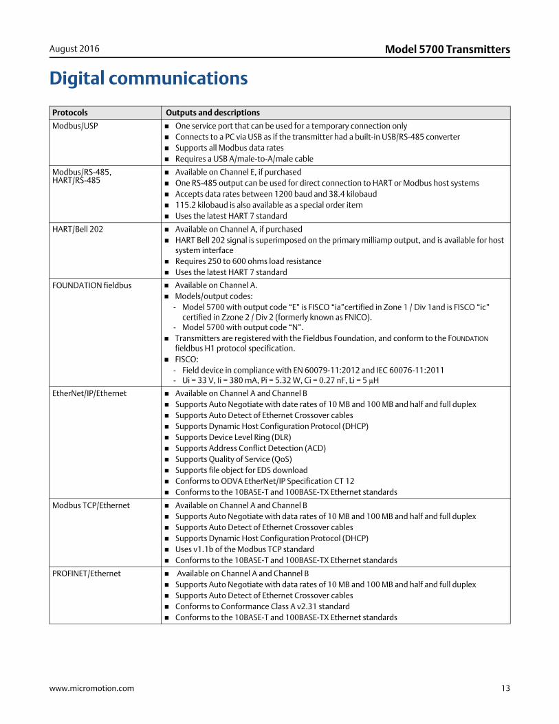
Digital communications
Protocols Outputs and descriptions
Modbus/USP One service port that can be used for a temporary connection only Connects to a PC via USB as if the transmitter had a built-in USB/RS-485 converter Supports all Modbus data rates Requires a USB A/male-to-A/male cable
Modbus/RS-485,HART/RS-485
Available on Channel E, if purchased One RS-485 output can be used for direct connection to HART or Modbus host systems Accepts data rates between 1200 baud and 38.4 kilobaud 115.2 kilobaud is also available as a special order item Uses the latest HART 7 standard
HART/Bell 202 Available on Channel A, if purchased HART Bell 202 signal is superimposed on the primary milliamp output, and is available for host
system interface Requires 250 to 600 ohms load resistance Uses the latest HART 7 standard
FOUNDATION fieldbus Available on Channel A. Models/output codes:
- Model 5700 with output code “E” is FISCO “ia”certified in Zone 1 / Div 1and is FISCO “ic” certified in Zzone 2 / Div 2 (formerly known as FNICO).
- Model 5700 with output code “N”. Transmitters are registered with the Fieldbus Foundation, and conform to the FOUNDATION
fieldbus H1 protocol specification. FISCO:
- Field device in compliance with EN 60079-11:2012 and IEC 60076-11:2011- Ui = 33 V, Ii = 380 mA, Pi = 5.32 W, Ci = 0.27 nF, Li = 5 μH
EtherNet/IP/Ethernet Available on Channel A and Channel B Supports Auto Negotiate with date rates of 10 MB and 100 MB and half and full duplex Supports Auto Detect of Ethernet Crossover cables Supports Dynamic Host Configuration Protocol (DHCP) Supports Device Level Ring (DLR) Supports Address Conflict Detection (ACD) Supports Quality of Service (QoS) Supports file object for EDS download Conforms to ODVA EtherNet/IP Specification CT 12 Conforms to the 10BASE-T and 100BASE-TX Ethernet standards
Modbus TCP/Ethernet Available on Channel A and Channel B Supports Auto Negotiate with data rates of 10 MB and 100 MB and half and full duplex Supports Auto Detect of Ethernet Crossover cables Supports Dynamic Host Configuration Protocol (DHCP) Uses v1.1b of the Modbus TCP standard Conforms to the 10BASE-T and 100BASE-TX Ethernet standards
PROFINET/Ethernet Available on Channel A and Channel B Supports Auto Negotiate with data rates of 10 MB and 100 MB and half and full duplex Supports Auto Detect of Ethernet Crossover cables Conforms to Conformance Class A v2.31 standard Conforms to the 10BASE-T and 100BASE-TX Ethernet standards
14 www.micromotion.com
Model 5700 Transmitters August 2016
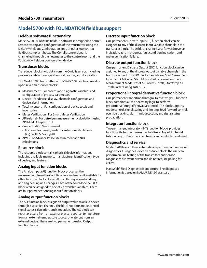
Model 5700 with FOUNDATION fieldbus support
Fieldbus software functionalityModel 5700 FOUNDATION fieldbus software is designed to permit remote testing and configuration of the transmitter using the DeltaV™ Fieldbus Configuration Tool, or other FOUNDATION fieldbus compliant hosts. The Coriolis sensor signal is channelled through the flowmeter to the control room and the FOUNDATION fieldbus configuration device.
Transducer blocksTransducer blocks hold data from the Coriolis sensor, including process variables, configuration, calibration, and diagnostics.
The Model 5700 transmitter with FOUNDATION fieldbus provides up to seven transducer blocks:
Measurement - For process and diagnostic variables and configuration of process parameters.
Device - For device, display, channels configuration and device alert information
Total inventory - For configuration of device totals and inventories
Meter Verification - For Smart Meter Verification API referral - For petroleum measurement calculations using
API MPMS Chapter 11.1 Concentration Measurement
- For complex density and concentration calculations (e.g.,%HFCS, SG60/60)
APM - For Advance Phase Measurement and NOC calculations
Resource blockThe resource block contains physical device information, including available memory, manufacturer identification, type of device, and features.
Analog input function blocksThe Analog Input (AI) function block processes the measurement from the Coriolis sensor and makes it available to other function blocks. It also allows filtering, alarm handling, and engineering unit changes. Each of the four Model 5700 AI blocks can be assigned to one of 27 available variables. There are four permanent Analog Input function blocks.
Analog output function blocksThe AO function block assigns an output value to a field device through a specified channel. The block supports mode control, signal status calculation, and simulation. The AO block can report pressure from an external pressure source, temperature from an external temperature source, or watercut from an external device. There are two permanent Analog Output function blocks.
Discrete input function blockOne permanent Discrete Input (DI) function block can be assigned to any of the discrete input variable channels in the transducer block. The DI block channels are: forward/reverse indication, zero in progress, fault condition indication, and meter verification failure.
Discrete output function blockOne permanent Discrete Output (DO) function block can be assigned to any of the discrete output variable channels in the transducer block. The DO block channels are: Start Sensor Zero, Increment CM Curve, Start Meter Verification in Continuous Measurement Mode, Reset All Process Totals, Start/Stop All Totals, Reset Config Totals 1-7.
Proportional integral derivative function blockOne permanent Proportional Integral Derivative (PID) function block combines all the necessary logic to perform proportional/integral/derivative control. The block supports mode control, signal scaling and limiting, feed forward control, override tracking, alarm limit detection, and signal status propagation.
Integrator function blockTwo permanent Integrator (INT) function blocks provides functionality for the transmitter totalizers. Any of 7 internal totals or any of 7 internal inventories can be selected and reset.
Diagnostics and serviceModel 5700 transmitters automatically perform continuous self diagnostics. Using the Device transducer block, the user can perform on-line testing of the transmitter and sensor. Diagnostics are event driven and do not require polling for access.
PlantWeb® Field Diagnostic is supported. The diagnostic information is based on NAMUR NE 107 standard.
www.micromotion.com 15
August 2016 Model 5700 Transmitters
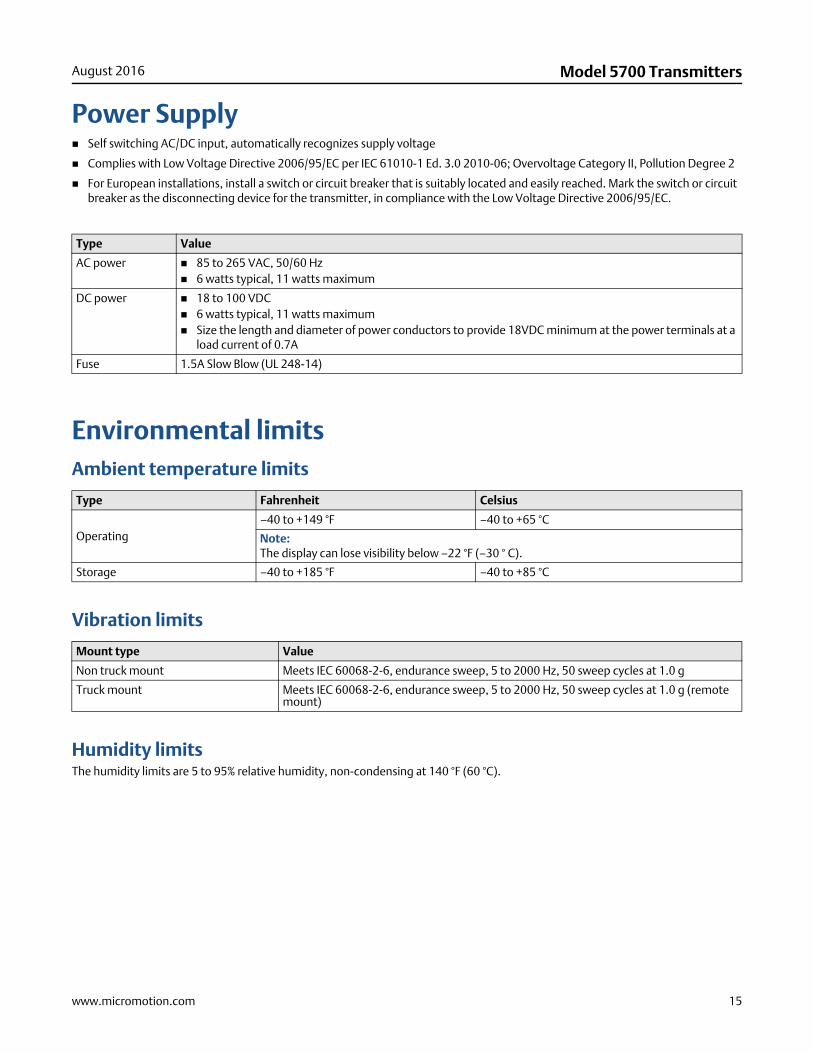
Power Supply Self switching AC/DC input, automatically recognizes supply voltage
Complies with Low Voltage Directive 2006/95/EC per IEC 61010-1 Ed. 3.0 2010-06; Overvoltage Category II, Pollution Degree 2
For European installations, install a switch or circuit breaker that is suitably located and easily reached. Mark the switch or circuit breaker as the disconnecting device for the transmitter, in compliance with the Low Voltage Directive 2006/95/EC.
Environmental limitsAmbient temperature limits
Vibration limits
Humidity limitsThe humidity limits are 5 to 95% relative humidity, non-condensing at 140 °F (60 °C).
Type Value
AC power 85 to 265 VAC, 50/60 Hz 6 watts typical, 11 watts maximum
DC power 18 to 100 VDC 6 watts typical, 11 watts maximum Size the length and diameter of power conductors to provide 18VDC minimum at the power terminals at a
load current of 0.7A
Fuse 1.5A Slow Blow (UL 248-14)
Type Fahrenheit Celsius
Operating–40 to +149 °F –40 to +65 °C
Note:The display can lose visibility below –22 °F (–30 ° C).
Storage –40 to +185 °F –40 to +85 °C
Mount type Value
Non truck mount Meets IEC 60068-2-6, endurance sweep, 5 to 2000 Hz, 50 sweep cycles at 1.0 g
Truck mount Meets IEC 60068-2-6, endurance sweep, 5 to 2000 Hz, 50 sweep cycles at 1.0 g (remote mount)
16 www.micromotion.com
Model 5700 Transmitters August 2016
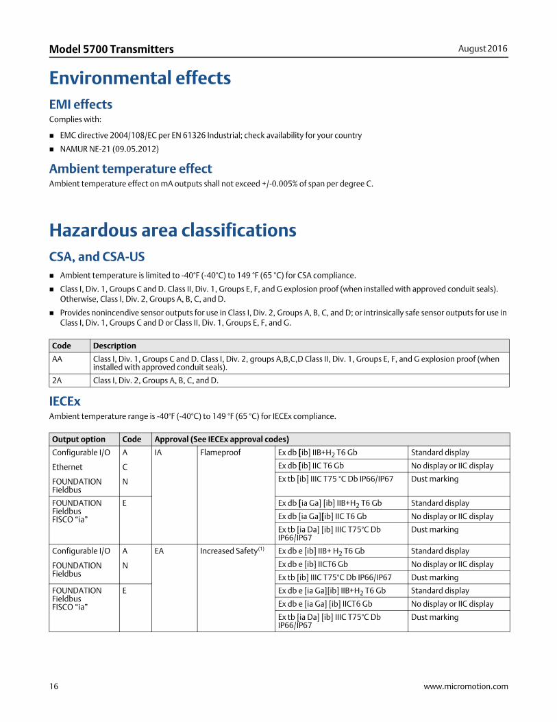
Environmental effectsEMI effectsComplies with:
EMC directive 2004/108/EC per EN 61326 Industrial; check availability for your country
NAMUR NE-21 (09.05.2012)
Ambient temperature effectAmbient temperature effect on mA outputs shall not exceed +/-0.005% of span per degree C.
Hazardous area classificationsCSA, and CSA-US Ambient temperature is limited to -40°F (-40°C) to 149 °F (65 °C) for CSA compliance.
Class I, Div. 1, Groups C and D. Class II, Div. 1, Groups E, F, and G explosion proof (when installed with approved conduit seals). Otherwise, Class I, Div. 2, Groups A, B, C, and D.
Provides nonincendive sensor outputs for use in Class I, Div. 2, Groups A, B, C, and D; or intrinsically safe sensor outputs for use in Class I, Div. 1, Groups C and D or Class II, Div. 1, Groups E, F, and G.
IECExAmbient temperature range is -40°F (-40°C) to 149 °F (65 °C) for IECEx compliance.
Code Description
AA Class I, Div. 1, Groups C and D. Class I, Div. 2, groups A,B,C,D Class II, Div. 1, Groups E, F, and G explosion proof (when installed with approved conduit seals).
2A Class I, Div. 2, Groups A, B, C, and D.
Output option Code Approval (See IECEx approval codes)
Configurable I/O
Ethernet
FOUNDATION Fieldbus
A
C
N
IA Flameproof Ex db [ib] IIB+H2 T6 Gb Standard display
Ex db [ib] IIC T6 Gb No display or IIC display
Ex tb [ib] IIIC T75 °C Db IP66/IP67 Dust marking
FOUNDATION FieldbusFISCO “ia”
E Ex db [ia Ga] [ib] IIB+H2 T6 Gb Standard display
Ex db [ia Ga][ib] IIC T6 Gb No display or IIC display
Ex tb [ia Da] [ib] IIIC T75°C Db IP66/IP67
Dust marking
Configurable I/O
FOUNDATION Fieldbus
A
N
EA Increased Safety(1) Ex db e [ib] IIB+ H2 T6 Gb Standard display
Ex db e [ib IICT6 Gb No display or IIC display
Ex tb [ib] IIIC T75°C Db IP66/IP67 Dust marking
FOUNDATION FieldbusFISCO “ia”
E Ex db e [ia Ga][ib] IIB+H2 T6 Gb Standard display
Ex db e [ia Ga] [ib] IICT6 Gb No display or IIC display
Ex tb [ia Da] [ib] IIIC T75°C Db IP66/IP67
Dust marking
www.micromotion.com 17
August 2016 Model 5700 Transmitters
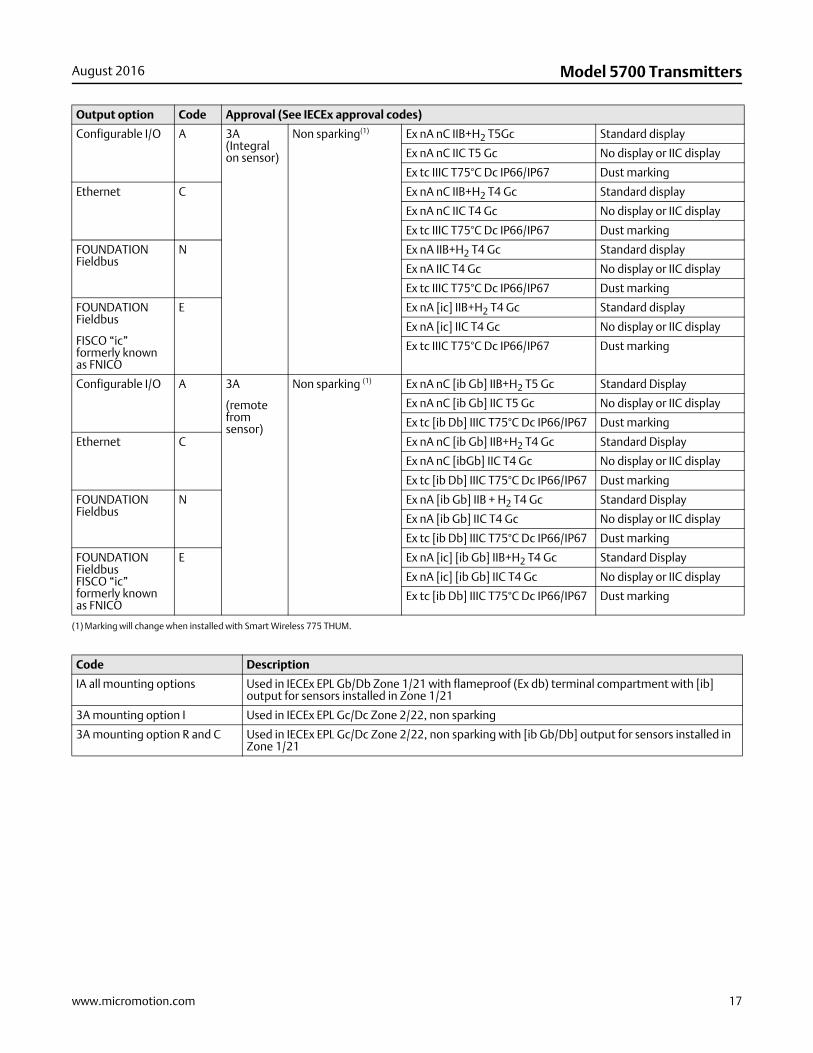
Configurable I/O A 3A (Integral on sensor)
Non sparking(1) Ex nA nC IIB+H2 T5Gc Standard display
Ex nA nC IIC T5 Gc No display or IIC display
Ex tc IIIC T75°C Dc IP66/IP67 Dust marking
Ethernet C Ex nA nC IIB+H2 T4 Gc Standard display
Ex nA nC IIC T4 Gc No display or IIC display
Ex tc IIIC T75°C Dc IP66/IP67 Dust marking
FOUNDATION Fieldbus
N Ex nA IIB+H2 T4 Gc Standard display
Ex nA IIC T4 Gc No display or IIC display
Ex tc IIIC T75°C Dc IP66/IP67 Dust marking
FOUNDATION Fieldbus
FISCO “ic” formerly known as FNICO
E Ex nA [ic] IIB+H2 T4 Gc Standard display
Ex nA [ic] IIC T4 Gc No display or IIC display
Ex tc IIIC T75°C Dc IP66/IP67 Dust marking
Configurable I/O A 3A
(remote from sensor)
Non sparking (1) Ex nA nC [ib Gb] IIB+H2 T5 Gc Standard Display
Ex nA nC [ib Gb] IIC T5 Gc No display or IIC display
Ex tc [ib Db] IIIC T75°C Dc IP66/IP67 Dust marking
Ethernet C Ex nA nC [ib Gb] IIB+H2 T4 Gc Standard Display
Ex nA nC [ibGb] IIC T4 Gc No display or IIC display
Ex tc [ib Db] IIIC T75°C Dc IP66/IP67 Dust marking
FOUNDATION Fieldbus
N Ex nA [ib Gb] IIB + H2 T4 Gc Standard Display
Ex nA [ib Gb] IIC T4 Gc No display or IIC display
Ex tc [ib Db] IIIC T75°C Dc IP66/IP67 Dust marking
FOUNDATION FieldbusFISCO “ic” formerly known as FNICO
E Ex nA [ic] [ib Gb] IIB+H2 T4 Gc Standard Display
Ex nA [ic] [ib Gb] IIC T4 Gc No display or IIC display
Ex tc [ib Db] IIIC T75°C Dc IP66/IP67 Dust marking
(1) Marking will change when installed with Smart Wireless 775 THUM.
Code Description
IA all mounting options Used in IECEx EPL Gb/Db Zone 1/21 with flameproof (Ex db) terminal compartment with [ib] output for sensors installed in Zone 1/21
3A mounting option I Used in IECEx EPL Gc/Dc Zone 2/22, non sparking
3A mounting option R and C Used in IECEx EPL Gc/Dc Zone 2/22, non sparking with [ib Gb/Db] output for sensors installed in Zone 1/21
Output option Code Approval (See IECEx approval codes)
18 www.micromotion.com
Model 5700 Transmitters August 2016
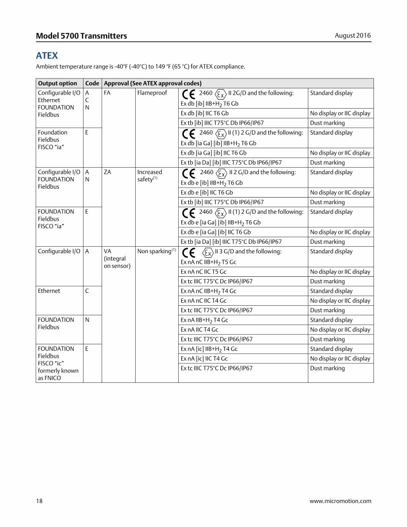
ATEXAmbient temperature range is -40°F (-40°C) to 149 °F (65 °C) for ATEX compliance.
Output option Code Approval (See ATEX approval codes)
Configurable I/OEthernetFOUNDATION Fieldbus
ACN
FA Flameproof 2460 II 2G/D and the following:
Ex db [ib] IIB+H2 T6 Gb
Standard display
Ex db [ib] IIC T6 Gb No display or IIC display
Ex tb [ib] IIIC T75°C Db IP66/IP67 Dust marking
Foundation Fieldbus FISCO “ia”
E 2460 II (1) 2 G/D and the following:
Ex db [ia Ga] [ib] IIB+H2 T6 Gb
Standard display
Ex db [ia Ga] [ib] IIC T6 Gb No display or IIC display
Ex tb [ia Da] [ib] IIIC T75°C Db IP66/IP67 Dust marking
Configurable I/OFOUNDATION Fieldbus
AN
ZA Increased safety(1)
2460 II 2 G/D and the following:
Ex db e [ib] IIB+H2 T6 Gb
Standard display
Ex db e [ib] IIC T6 Gb No display or IIC display
Ex tb [ib] IIIC T75°C Db IP66/IP67 Dust marking
FOUNDATION FieldbusFISCO “ia”
E 2460 II (1) 2 G/D and the following:
Ex db e [ia Ga] [ib] IIB+H2 T6 Gb
Standard display
Ex db e [ia Ga] [ib] IIC T6 Gb No display or IIC display
Ex tb [ia Da] [ib] IIIC T75°C Db IP66/IP67 Dust marking
Configurable I/O A VA (integral on sensor)
Non sparking(1) II 3 G/D and the following:
Ex nA nC IIB+H2 T5 Gc
Standard display
Ex nA nC IIC T5 Gc No display or IIC display
Ex tc IIIC T75°C Dc IP66/IP67 Dust marking
Ethernet C Ex nA nC IIB+H2 T4 Gc Standard display
Ex nA nC IIC T4 Gc No display or IIC display
Ex tc IIIC T75°C Dc IP66/IP67 Dust marking
FOUNDATION Fieldbus
N Ex nA IIB+H2 T4 Gc Standard display
Ex nA IIC T4 Gc No display or IIC display
Ex tc IIIC T75°C Dc IP66/IP67 Dust marking
FOUNDATION Fieldbus FISCO “ic” formerly known as FNICO
E Ex nA [ic] IIB+H2 T4 Gc Standard display
Ex nA [ic] IIC T4 Gc No display or IIC display
Ex tc IIIC T75°C Dc IP66/IP67 Dust marking
www.micromotion.com 19
August 2016 Model 5700 Transmitters
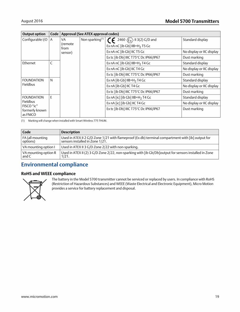
Environmental compliance
RoHS and WEEE complianceThe battery in the Model 5700 transmitter cannot be serviced or replaced by users. In compliance with RoHS (Restriction of Hazardous Substances) and WEEE (Waste Electrical and Electronic Equipment), Micro Motion provides a service for battery replacement and disposal.
Configurable I/O A VA(remote from sensor)
Non sparking(1) 2460 II 3(2) G/D and
Ex nA nC [ib Gb] IIB+H2 T5 Gc
Standard display
Ex nA nC [ib Gb] IIC T5 Gc No display or IIC display
Ex tc [ib Db] IIIC T75°C Dc IP66/IP67 Dust marking
Ethernet C Ex nA nC [ib Gb] IIB+H2 T4 Gc Standard display
Ex nA nC [ib Gb] IIC T4 Gc No display or IIC display
Ex tc [ib Db] IIIC T75°C Dc IP66/IP67 Dust marking
FOUNDATION Fieldbus
N Ex nA [ib Gb] IIB+H2 T4 Gc Standard display
Ex nA [ib Gb] IIC T4 Gc No display or IIC display
Ex tc [ib Db] IIIC T75°C Dc IP66/IP67 Dust marking
FOUNDATION Fieldbus FISCO “ic” formerly known as FNICO
E Ex nA [ic] [ib Gb] IIB+H2 T4 Gc Standard display
Ex nA [ic] [ib Gb] IIC T4 Gc No display or IIC display
Ex tc [ib Db] IIIC T75°C Dc IP66/IP67 Dust marking
(1) Marking will change when installed with Smart Wireless 775 THUM.
Code Description
FA (all mounting options)
Used in ATEX II 2 G/D Zone 1/21 with flameproof (Ex db) terminal compartment with [ib] output for sensors installed in Zone 1/21.
VA mounting option I Used in ATEX II 3 G/D Zone 2/22 with non-sparking.
VA mounting option R and C
Used in ATEX II (2) 3 G/D Zone 2/22, non-sparking with [ib Gb/Db]output for sensors installed in Zone 1/21.
Output option Code Approval (See ATEX approval codes)
20 www.micromotion.com
Model 5700 Transmitters August 2016
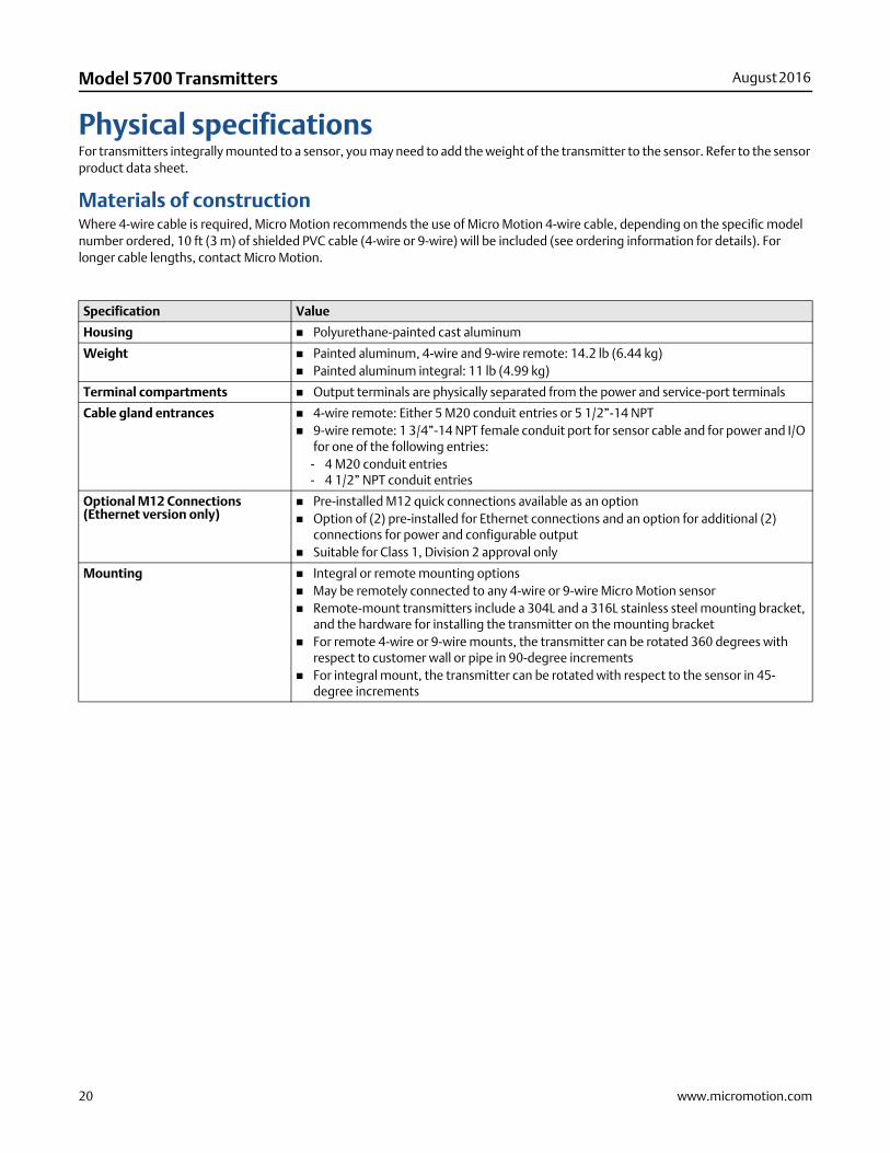
Physical specificationsFor transmitters integrally mounted to a sensor, you may need to add the weight of the transmitter to the sensor. Refer to the sensor product data sheet.
Materials of constructionWhere 4-wire cable is required, Micro Motion recommends the use of Micro Motion 4-wire cable, depending on the specific model number ordered, 10 ft (3 m) of shielded PVC cable (4-wire or 9-wire) will be included (see ordering information for details). For longer cable lengths, contact Micro Motion.
Specification Value
Housing Polyurethane-painted cast aluminum
Weight Painted aluminum, 4-wire and 9-wire remote: 14.2 lb (6.44 kg) Painted aluminum integral: 11 lb (4.99 kg)
Terminal compartments Output terminals are physically separated from the power and service-port terminals
Cable gland entrances 4-wire remote: Either 5 M20 conduit entries or 5 1/2”-14 NPT 9-wire remote: 1 3/4”-14 NPT female conduit port for sensor cable and for power and I/O
for one of the following entries:- 4 M20 conduit entries- 4 1/2” NPT conduit entries
Optional M12 Connections (Ethernet version only)
Pre-installed M12 quick connections available as an option Option of (2) pre-installed for Ethernet connections and an option for additional (2)
connections for power and configurable output Suitable for Class 1, Division 2 approval only
Mounting Integral or remote mounting options May be remotely connected to any 4-wire or 9-wire Micro Motion sensor Remote-mount transmitters include a 304L and a 316L stainless steel mounting bracket,
and the hardware for installing the transmitter on the mounting bracket For remote 4-wire or 9-wire mounts, the transmitter can be rotated 360 degrees with
respect to customer wall or pipe in 90-degree increments For integral mount, the transmitter can be rotated with respect to the sensor in 45-
degree increments
www.micromotion.com 21
August 2016 Model 5700 Transmitters
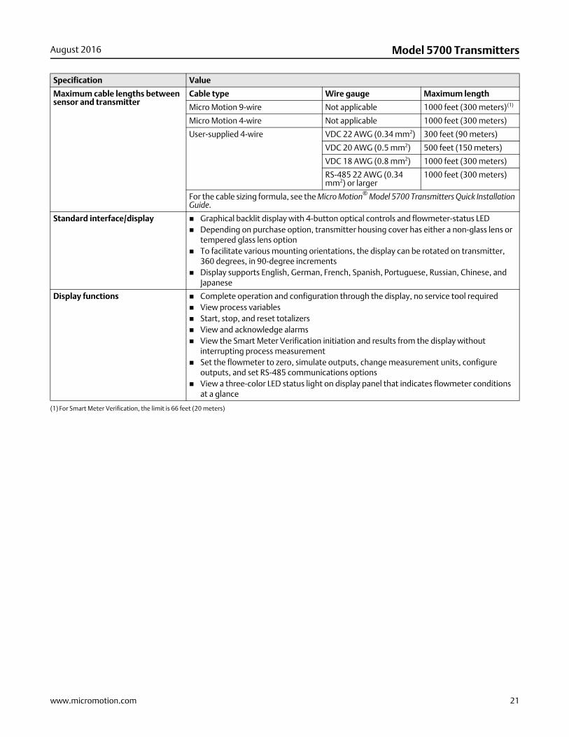
Maximum cable lengths between sensor and transmitter
Cable type Wire gauge Maximum length
Micro Motion 9-wire Not applicable 1000 feet (300 meters)(1)
Micro Motion 4-wire Not applicable 1000 feet (300 meters)
User-supplied 4-wire VDC 22 AWG (0.34 mm2) 300 feet (90 meters)
VDC 20 AWG (0.5 mm2) 500 feet (150 meters)
VDC 18 AWG (0.8 mm2) 1000 feet (300 meters)
RS-485 22 AWG (0.34 mm2) or larger
1000 feet (300 meters)
For the cable sizing formula, see the Micro Motion® Model 5700 Transmitters Quick Installation Guide.
Standard interface/display Graphical backlit display with 4-button optical controls and flowmeter-status LED Depending on purchase option, transmitter housing cover has either a non-glass lens or
tempered glass lens option To facilitate various mounting orientations, the display can be rotated on transmitter,
360 degrees, in 90-degree increments Display supports English, German, French, Spanish, Portuguese, Russian, Chinese, and
Japanese
Display functions Complete operation and configuration through the display, no service tool required View process variables Start, stop, and reset totalizers View and acknowledge alarms View the Smart Meter Verification initiation and results from the display without
interrupting process measurement Set the flowmeter to zero, simulate outputs, change measurement units, configure
outputs, and set RS-485 communications options View a three-color LED status light on display panel that indicates flowmeter conditions
at a glance
(1) For Smart Meter Verification, the limit is 66 feet (20 meters)
Specification Value
22 www.micromotion.com
Model 5700 Transmitters August 2016
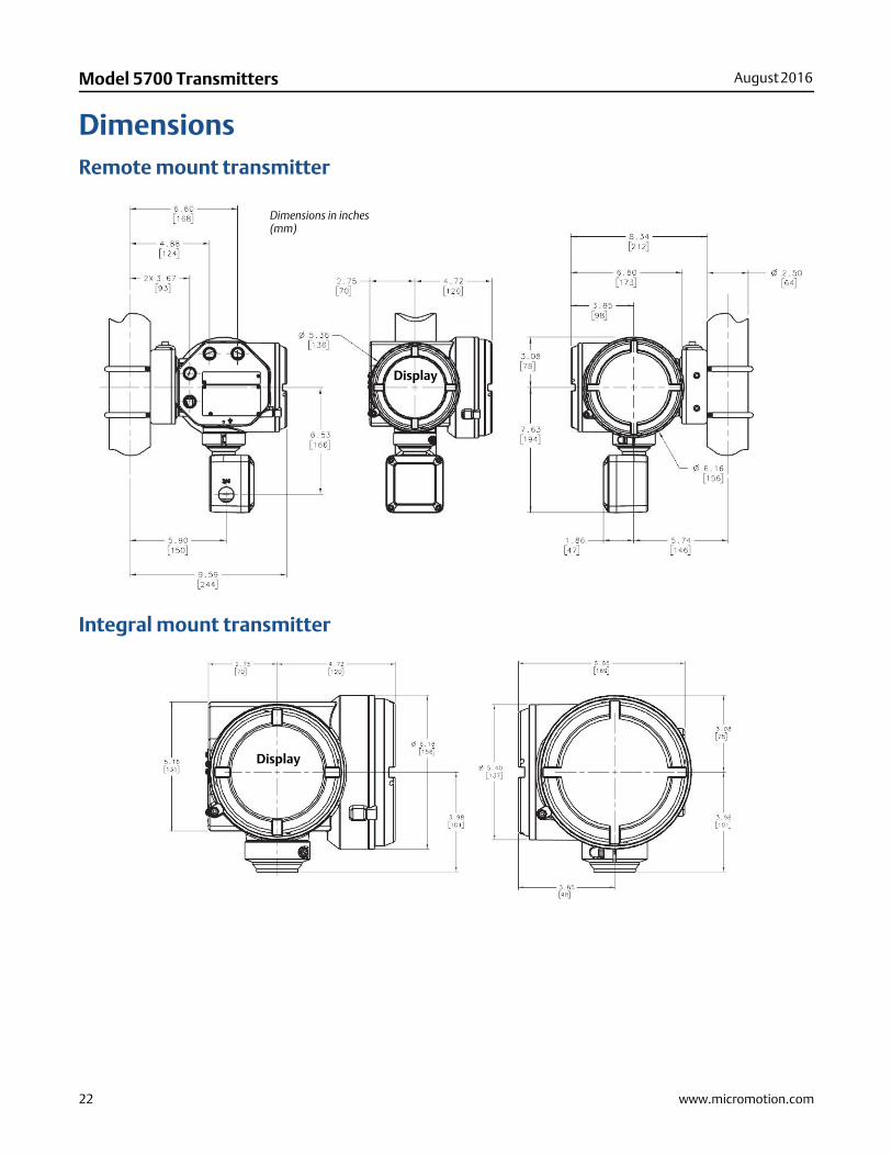
DimensionsRemote mount transmitter
Integral mount transmitter
Dimensions in inches(mm)
Display
Display
www.micromotion.com 23
August 2016 Model 5700 Transmitters
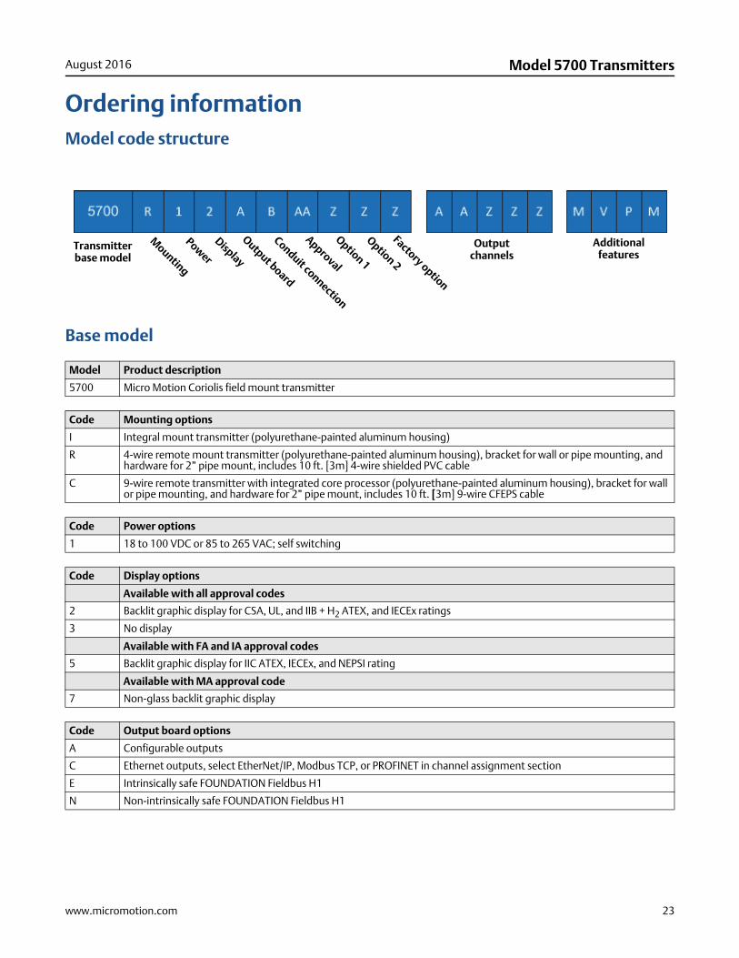
Ordering informationModel code structure
Base model
Model Product description
5700 Micro Motion Coriolis field mount transmitter
Code Mounting options
I Integral mount transmitter (polyurethane-painted aluminum housing)
R 4-wire remote mount transmitter (polyurethane-painted aluminum housing), bracket for wall or pipe mounting, and hardware for 2” pipe mount, includes 10 ft. [3m] 4-wire shielded PVC cable
C 9-wire remote transmitter with integrated core processor (polyurethane-painted aluminum housing), bracket for wall or pipe mounting, and hardware for 2” pipe mount, includes 10 ft. [3m] 9-wire CFEPS cable
Code Power options
1 18 to 100 VDC or 85 to 265 VAC; self switching
Code Display options
Available with all approval codes
2 Backlit graphic display for CSA, UL, and IIB + H2 ATEX, and IECEx ratings
3 No display
Available with FA and IA approval codes
5 Backlit graphic display for IIC ATEX, IECEx, and NEPSI rating
Available with MA approval code
7 Non-glass backlit graphic display
Code Output board options
A Configurable outputs
C Ethernet outputs, select EtherNet/IP, Modbus TCP, or PROFINET in channel assignment section
E Intrinsically safe FOUNDATION Fieldbus H1
N Non-intrinsically safe FOUNDATION Fieldbus H1
Mounting
Transmitterbase model
Power
Display
Output board
Conduit connection
Approval
Option 1
Option 2
Output channels
Additional features
Factory option
24 www.micromotion.com
Model 5700 Transmitters August 2016
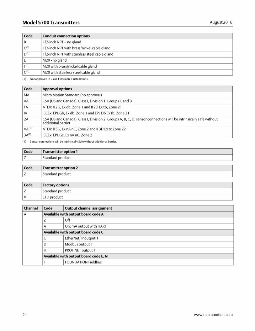
Code Conduit connection options
B 1/2-inch NPT – no gland
C(1) 1/2-inch NPT with brass/nickel cable gland
D(1) 1/2-inch NPT with stainless steel cable gland
E M20 - no gland
F(1) M20 with brass/nickel cable gland
G(1) M20 with stainless steel cable gland
(1) Not approved in Class 1 Division 1 installations.
Code Approval options
MA Micro Motion Standard (no approval)
AA CSA (US and Canada): Class I, Division 1, Groups C and D
FA ATEX: II 2G, Ex db, Zone 1 and II 2D Ex tb, Zone 21
IA IECEx: EPL Gb, Ex db, Zone 1 and EPL Db Ex tb, Zone 21
2A CSA (US and Canada): Class I, Division 2, Groups A, B, C, D; sensor connections will be intrinsically safe without additional barrier
VA(1) ATEX: II 3G, Ex nA nC, Zone 2 and II 3D Ex tc Zone 22
3A(1) IECEx: EPL Gc, Ex nA nC, Zone 2
(1) Sensor connections will be Intrinsically Safe without additional barrier.
Code Transmitter option 1
Z Standard product
Code Transmitter option 2
Z Standard product
Code Factory options
Z Standard product
X ETO product
Channel Code Output channel assignment
A Available with output board code A
Z Off
A On; mA output with HART
Available with output board code C
C EtherNet/IP output 1
D Modbus output 1
H PROFINET output 1
Available with output board code E, N
F FOUNDATION Fieldbus
www.micromotion.com 25
August 2016 Model 5700 Transmitters
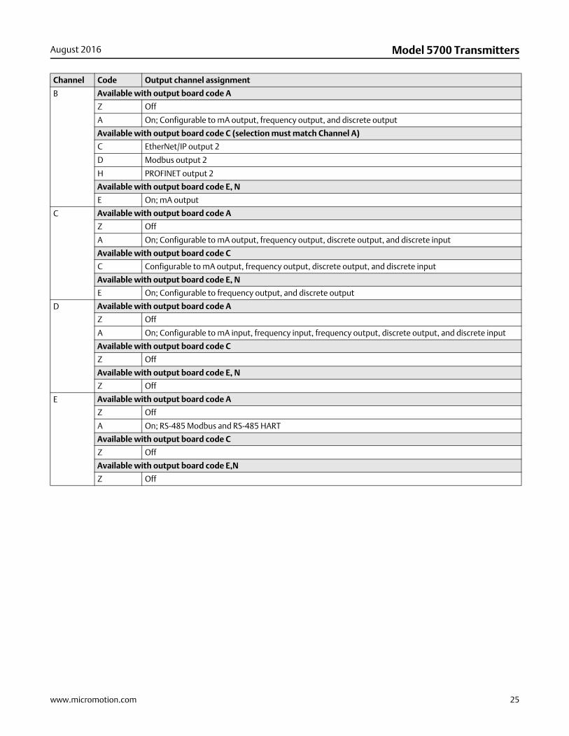
B Available with output board code A
Z Off
A On; Configurable to mA output, frequency output, and discrete output
Available with output board code C (selection must match Channel A)
C EtherNet/IP output 2
D Modbus output 2
H PROFINET output 2
Available with output board code E, N
E On; mA output
C Available with output board code A
Z Off
A On; Configurable to mA output, frequency output, discrete output, and discrete input
Available with output board code C
C Configurable to mA output, frequency output, discrete output, and discrete input
Available with output board code E, N
E On; Configurable to frequency output, and discrete output
D Available with output board code A
Z Off
A On; Configurable to mA input, frequency input, frequency output, discrete output, and discrete input
Available with output board code C
Z Off
Available with output board code E, N
Z Off
E Available with output board code A
Z Off
A On; RS-485 Modbus and RS-485 HART
Available with output board code C
Z Off
Available with output board code E,N
Z Off
Channel Code Output channel assignment
26 www.micromotion.com
Model 5700 Transmitters August 2016
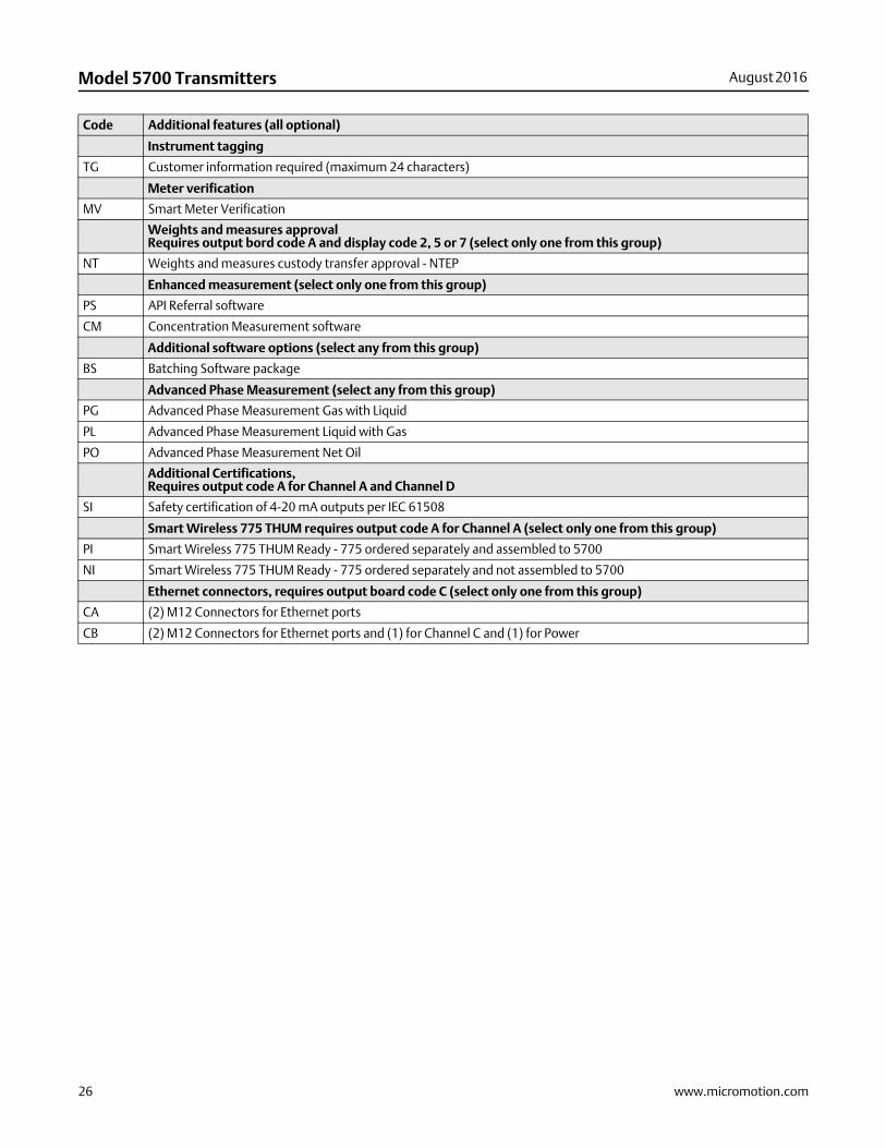
Code Additional features (all optional)
Instrument tagging
TG Customer information required (maximum 24 characters)
Meter verification
MV Smart Meter Verification
Weights and measures approvalRequires output bord code A and display code 2, 5 or 7 (select only one from this group)
NT Weights and measures custody transfer approval - NTEP
Enhanced measurement (select only one from this group)
PS API Referral software
CM Concentration Measurement software
Additional software options (select any from this group)
BS Batching Software package
Advanced Phase Measurement (select any from this group)
PG Advanced Phase Measurement Gas with Liquid
PL Advanced Phase Measurement Liquid with Gas
PO Advanced Phase Measurement Net Oil
Additional Certifications, Requires output code A for Channel A and Channel D
SI Safety certification of 4-20 mA outputs per IEC 61508
Smart Wireless 775 THUM requires output code A for Channel A (select only one from this group)
PI Smart Wireless 775 THUM Ready - 775 ordered separately and assembled to 5700
NI Smart Wireless 775 THUM Ready - 775 ordered separately and not assembled to 5700
Ethernet connectors, requires output board code C (select only one from this group)
CA (2) M12 Connectors for Ethernet ports
CB (2) M12 Connectors for Ethernet ports and (1) for Channel C and (1) for Power

Model 5700 TransmittersPS-001885, Rev. F
Product Data SheetAugust 2016
Emerson Process Management Emerson Process ManagementAmericas Europe/Middle East7070 Winchester Circle Central & Eastern Europe T: +41 41 7686 111Boulder, Colorado USA 80301 Dubai T: +971 4 811 8100www.MicroMotion.com Abu Dhabi T: +971 2 697 2000www.Rosemount.com France T: 0800 917 901T: +1 800 522 6277 Germany T: 0800 182 5347T: +1 (303) 527 5200 Italy T: 8008 77334F: +1 (303) 530 8459 The Netherlands T: +31 (0) 70 413 6666
Belgium T: +32 2 716 77 11Mexico T: 52 55 5809 5300 Spain T: +34 913 586 000Argentina T: 54 11 4837 7000 U.K. T: 0870 240 1978Brazil T: 55 15 3413 8000 Russia/CIS T: +7 495 981 9811Venezuela T: 58 26 1300 8100Chile T: 56 2 2928 4800
Emerson Process ManagementAsia PacificAustralia T: (61) 3 9721 0200China T: (86) 21 2892 9000India T: (91) 22 6662 0566Japan T: (81) 3 5769 6803South Korea T: (82) 2 3438 4600Singapore T: (65) 6 777 8211
© 201 Micro Motion, Inc. All rights reserved.
The Emerson logo is a trademark and service mark of Emerson Electric Co. Micro Motion, ELITE, ProLink, MVD and MVD Direct Connect marks are marks of one of the Emerson Process Management family of companies. All other marks are property of their respective owners.
Micro Motion supplies this publication for informational purposes only. While every effort has been made to ensure accuracy, this publication is notintended to make performance claims or process recommendations. Micro Motion does not warrant, guarantee, or assume any legal liability for theaccuracy, completeness, timeliness, reliability, or usefulness of any information, product, or process described herein. We reserve the right to modify or improve the designs or specifications of our products at any time wihout notice. For actual product information and recommendations, please contact your local Micro Motion representative.