Embed Size (px)
Citation preview

Series 8900 GC-PID Gas Chromatograph
Installation and User’s Manual
YMA-6900200 - Revision B, 6/30/05
Baseline – MOCON, Inc. P.O. Box 649
Lyons, Colorado 80540
Notice The Series 8900 Gas Chromatograph, and this manual are manufactured by Baseline - MOCON, Incorporated of Lyons, Colorado. Information in this document is subject to change without notice and does not represent a commitment on the part of Baseline - MOCON, Incorporated (hereafter, the Manufacturer). The instrument, and or software described in this document are furnished under a license agreement or nondisclosure agreement. No part of this manual may be reproduced or transmitted in any form or by any means, electronic or mechanical, including photocopying and recording, for any purpose without the express written permission of the Manufacturer.
The Manufacturer may have patents or pending patent applications, trademarks, copyrights or other intellectual property rights covering subject matter in this document. The furnishing of this document does not give you any license to these patents, trademarks, copyrights or other intellectual property rights.
Software provided with your instrument may be used or copied only in accordance with the terms of the agreement. However, it is against the law to copy the software on any medium except as specifically allowed in the license or nondisclosure agreement.
Software manufactured by Baseline - MOCON, Incorporated, may contain software components from Baseline's suppliers.
® Baseline Series is a registered trademark of Baseline - MOCON, Inc..
Microsoft, MS, MS-DOS, Windows, and Windows NT are trademarks of Microsoft Corporation. All other trademarks are the property of their respective companies and are used for information purposes only.
Copyright © Baseline - MOCON, Inc. 1996 - 2002. All rights reserved.
Printed and bound in the United States of America.
Instrument Warranty This manual must be carefully read and followed by all persons who have or will have the responsibility for using or servicing the product. Like any piece of complex equipment, the product will perform as designed only if it is used and serviced in accordance with the manufacturer's instructions. Otherwise, it could fail to perform as designed and persons who rely on this product for their safety could sustain severe personal injury or death.
The warranties made by Baseline - MOCON, Incorporated, with respect to the product are voided if the product is not used and serviced in accordance with the instructions in this manual. Please protect yourself and others by following them. We encourage our customers to write or call regarding this equipment prior to use, or for any additional information relative to use or repairs.
WARNING: FOR SAFETY REASONS, ONLY QUALIFIED PERSONNEL SHOULD OPERATE THIS EQUIPMENT.
ii

The Series 8900 Gas Chromatograph contains no user-serviceable parts. The interior of the instrument should not be accessed by anyone other than a Baseline authorized technician. Repair or alteration of the instrument beyond the scope of the instruction manual, by anyone other than a person authorized by Baseline - MOCON, could cause the analyzer to fail to perform as designed. When needed, use only genuine Baseline replacement parts. Substitution of components can impair instrument performance, alter its safety characteristics, or void agency approvals.
In the US, contact you’re nearest stocking location by dialing 1-800-321-4665.
iii
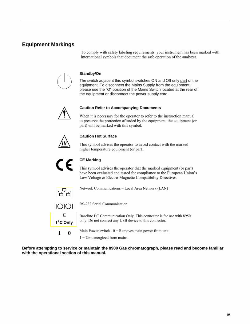
Equipment Markings To comply with safety labeling requirements, your instrument has been marked with international symbols that document the safe operation of the analyzer.
Standby/On
The switch adjacent this symbol switches ON and Off only part of the equipment. To disconnect the Mains Supply from the equipment, please use the “O” position of the Mains Switch located at the rear of the equipment or disconnect the power supply cord.
Caution Refer to Accompanying Documents
When it is necessary for the operator to refer to the instruction manual to preserve the protection afforded by the equipment, the equipment (or part) will be marked with this symbol.
Caution Hot Surface
This symbol advises the operator to avoid contact with the marked higher temperature equipment (or part).
CE Marking
This symbol advises the operator that the marked equipment (or part) have been evaluated and tested for compliance to the European Union’s Low Voltage & Electro-Magnetic Compatibility Directives.
Network Communications – Local Area Network (LAN)
RS-232 Serial Communication
E
I2C Only Baseline I2C Communication Only. This connector is for use with 8950 only. Do not connect any USB device to this connector.
1 0 Main Power switch - 0 = Removes main power from unit.
1 = Unit energized from mains. Before attempting to service or maintain the 8900 Gas chromatograph, please read and become familiar with the operational section of this manual.
iv

Table of Contents Section 1 – Overview and installation..................................................................................................................... 1-1
Introduction ......................................................................................................................................................... 1-1 Safety Documentation......................................................................................................................................... 1-2
Warnings & Cautions....................................................................................................................................... 1-2 Specifications………………………………………………………………………………………………………….. 1-3
Theory of Operation ............................................................................................................................................ 1-5 PID Theory ...................................................................................................................................................... 1-5 Analysis Theory ............................................................................................................................................... 1-5 Pneumatics...................................................................................................................................................... 1-6
System Electronics - General Information .......................................................................................................... 1-7 System Configurations .................................................................................................................................... 1-7 Electrical Connections..................................................................................................................................... 1-7 Gas Connections............................................................................................................................................. 1-9
Installing the Analyzer....................................................................................................................................... 1-10 Unpacking...................................................................................................................................................... 1-10 Installation Notes........................................................................................................................................... 1-11
Section 2 – Instrument Operation........................................................................................................................... 2-1 User Interface...................................................................................................................................................... 2-1
Description of the Front Panel Interface.......................................................................................................... 2-1 Home Screen ...................................................................................................................................................... 2-1
Reading the Instrument Status........................................................................................................................ 2-1 Peak and Port Messages ................................................................................................................................ 2-2 Alarm Messages.............................................................................................................................................. 2-2
Buttons in the Home Screen ............................................................................................................................... 2-2 Home Screen in the Normal State................................................................................................................... 2-2 Home Screen in the Alarmed State................................................................................................................. 2-2
Software Structure .............................................................................................................................................. 2-4 Options Menu...................................................................................................................................................... 2-5 Instrument Startup............................................................................................................................................... 2-6 Startup Instructions (Stand-alone operation) ...................................................................................................... 2-6 Startup Instructions (Operation with SkyChrom) ................................................................................................ 2-7 Startup Instructions (Start from Digital Input)...................................................................................................... 2-7 Performing an Unscheduled Calibration ............................................................................................................. 2-8 Startup Trouble Shooting .................................................................................................................................... 2-9
TEMP Alarm .................................................................................................................................................... 2-9 LAMP Alarm .................................................................................................................................................... 2-9
Shutdown Message .......................................................................................................................................... 2-10 Power Switch Do’s and Don’ts.......................................................................................................................... 2-11 Accidental Power Loss...................................................................................................................................... 2-12
While in Stand Alone Mode ........................................................................................................................... 2-12 When Controlled by SkyChrom..................................................................................................................... 2-12
Lamp Cleaning Procedure ................................................................................................................................ 2-13 Section 3 – Manual Mode....................................................................................................................................... 3-1
General ............................................................................................................................................................... 3-1 Options................................................................................................................................................................ 3-2 Manual Mode Commands................................................................................................................................... 3-2
Section 4 – Information Mode................................................................................................................................. 4-1 General ............................................................................................................................................................... 4-1 System Information ............................................................................................................................................. 4-2
Section 5 – Serial Communications........................................................................................................................ 5-1 General Information ............................................................................................................................................ 5-1 Data Shipped by the Analyzer (COM 1) ............................................................................................................. 5-1 Commands accepted by the analyzer. (COM 1)................................................................................................. 5-1 Communications framing parameters (COM 1) .................................................................................................. 5-1
v
Explanation of data fields (COM 1) ..................................................................................................................... 5-2 Stream............................................................................................................................................................. 5-2 Port .................................................................................................................................................................. 5-2 Concentration. ................................................................................................................................................. 5-2
Com 2 Protocol ................................................................................................................................................... 5-2 List of Figures Figure 1-1. Series 8900 PID GC Plumbing Diagram.............................................................................................. 1-6 Figure 2-1. Home Screen ....................................................................................................................................... 2-1 Figure 2-2. Reset Alarms Screen ........................................................................................................................... 2-3 Figure 2-3. Main Software Tree.............................................................................................................................. 2-4 Figure 2-4. Shutdown Screen............................................................................................................................... 2-10 Figure 3-1. Manual Mode, Main Menu Structure.................................................................................................... 3-1 Figure 4-1. Information Mode, Main Menu Structure.............................................................................................. 4-1 Figure 4-2. System Information, Menu Structure ................................................................................................... 4-2
vi
Section 1 – Overview and installation Introduction
The Series 8900 Gas Chromatograph is suitable for industrial and environmental applications. The instrument can be purchased in a variety of configurations. Your instrument has been built to your specifications.
An appendix section has been added to the back of this manual for your reference. This section identifies your analyzer by serial number, includes an inventory of all options and provides technical information specific to your application. Become familiar with this section, as it will be referenced through out this manual.
Finally, keep the appendix portion of this manual current. When calling for technical support, be sure to have it at hand.
Important Note Your instrument has been configured specifically for your application. DO NOT CHANGE PROGRAMMED VALUES BEFORE READING AND UNDERSTANDING THIS MANUAL. If the material presented here is unclear or conflicts with other information call the Baseline service department for clarification and/or resolution.
1-1
Overview and Installation
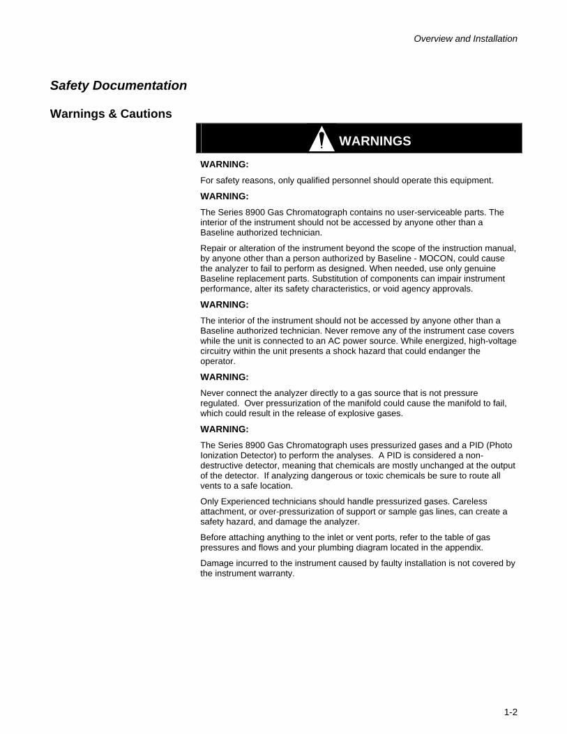
Safety Documentation
Warnings & Cautions
WARNINGS
WARNING: For safety reasons, only qualified personnel should operate this equipment.
WARNING: The Series 8900 Gas Chromatograph contains no user-serviceable parts. The interior of the instrument should not be accessed by anyone other than a Baseline authorized technician.
Repair or alteration of the instrument beyond the scope of the instruction manual, by anyone other than a person authorized by Baseline - MOCON, could cause the analyzer to fail to perform as designed. When needed, use only genuine Baseline replacement parts. Substitution of components can impair instrument performance, alter its safety characteristics, or void agency approvals.
WARNING: The interior of the instrument should not be accessed by anyone other than a Baseline authorized technician. Never remove any of the instrument case covers while the unit is connected to an AC power source. While energized, high-voltage circuitry within the unit presents a shock hazard that could endanger the operator.
WARNING: Never connect the analyzer directly to a gas source that is not pressure regulated. Over pressurization of the manifold could cause the manifold to fail, which could result in the release of explosive gases.
WARNING: The Series 8900 Gas Chromatograph uses pressurized gases and a PID (Photo Ionization Detector) to perform the analyses. A PID is considered a non-destructive detector, meaning that chemicals are mostly unchanged at the output of the detector. If analyzing dangerous or toxic chemicals be sure to route all vents to a safe location.
Only Experienced technicians should handle pressurized gases. Careless attachment, or over-pressurization of support or sample gas lines, can create a safety hazard, and damage the analyzer.
Before attaching anything to the inlet or vent ports, refer to the table of gas pressures and flows and your plumbing diagram located in the appendix.
Damage incurred to the instrument caused by faulty installation is not covered by the instrument warranty.
1-2
Overview and Installation
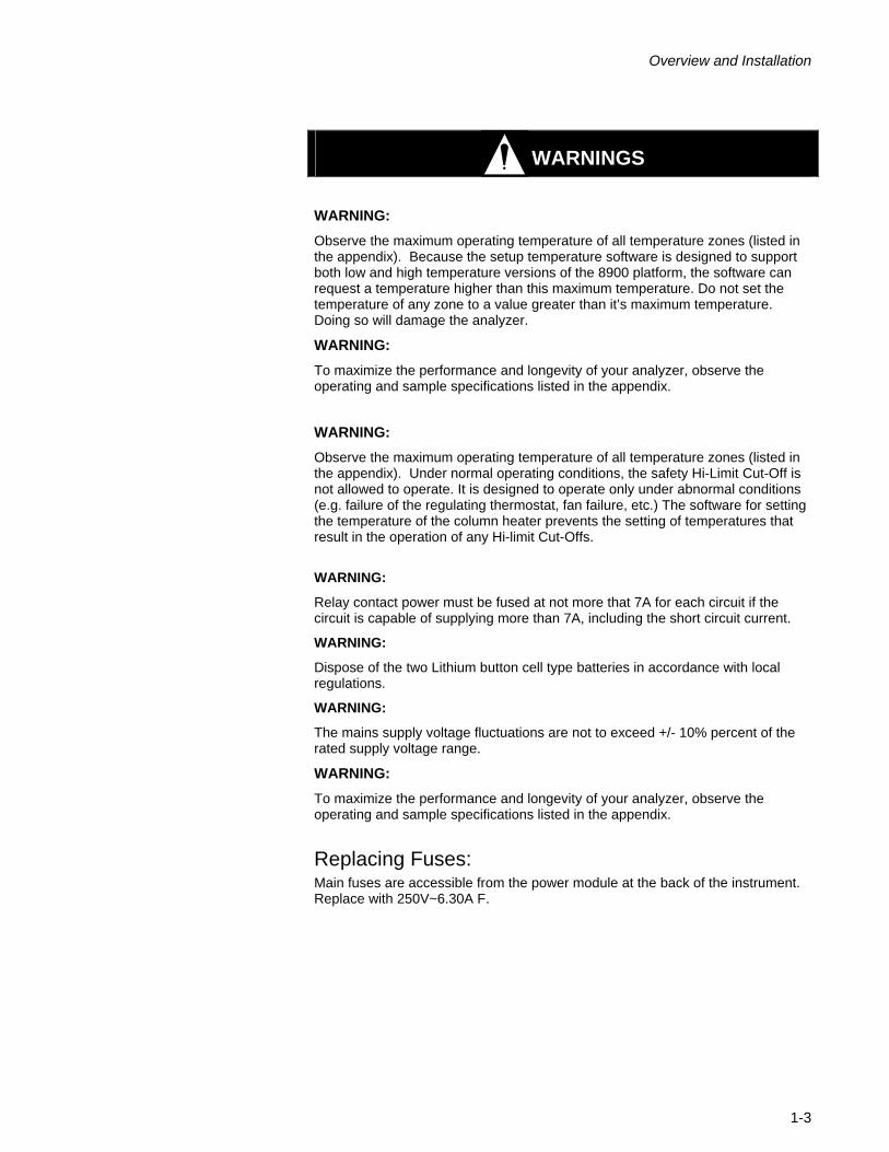
WARNINGS
WARNING: Observe the maximum operating temperature of all temperature zones (listed in the appendix). Because the setup temperature software is designed to support both low and high temperature versions of the 8900 platform, the software can request a temperature higher than this maximum temperature. Do not set the temperature of any zone to a value greater than it’s maximum temperature. Doing so will damage the analyzer.
WARNING: To maximize the performance and longevity of your analyzer, observe the operating and sample specifications listed in the appendix.
WARNING: Observe the maximum operating temperature of all temperature zones (listed in the appendix). Under normal operating conditions, the safety Hi-Limit Cut-Off is not allowed to operate. It is designed to operate only under abnormal conditions (e.g. failure of the regulating thermostat, fan failure, etc.) The software for setting the temperature of the column heater prevents the setting of temperatures that result in the operation of any Hi-limit Cut-Offs.
WARNING:
Relay contact power must be fused at not more that 7A for each circuit if the circuit is capable of supplying more than 7A, including the short circuit current.
WARNING:
Dispose of the two Lithium button cell type batteries in accordance with local regulations.
WARNING:
The mains supply voltage fluctuations are not to exceed +/- 10% percent of the rated supply voltage range.
WARNING: To maximize the performance and longevity of your analyzer, observe the operating and sample specifications listed in the appendix.
Replacing Fuses: Main fuses are accessible from the power module at the back of the instrument. Replace with 250V~6.30A F.
1-3
Overview and Installation
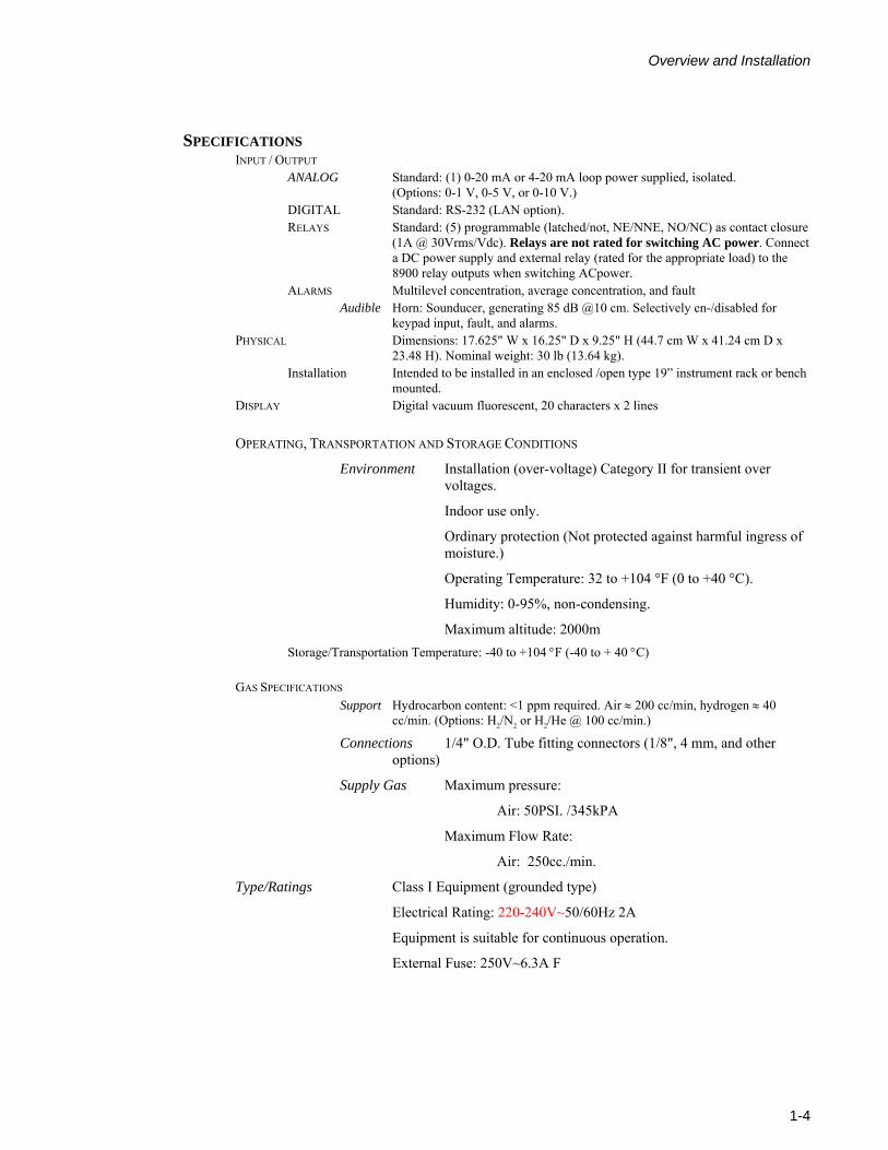
SPECIFICATIONS INPUT / OUTPUT
ANALOG Standard: (1) 0-20 mA or 4-20 mA loop power supplied, isolated. (Options: 0-1 V, 0-5 V, or 0-10 V.)
DIGITAL Standard: RS-232 (LAN option). RELAYS Standard: (5) programmable (latched/not, NE/NNE, NO/NC) as contact closure
(1A @ 30Vrms/Vdc). Relays are not rated for switching AC power. Connect a DC power supply and external relay (rated for the appropriate load) to the 8900 relay outputs when switching ACpower.
ALARMS Multilevel concentration, average concentration, and fault Audible Horn: Sounducer, generating 85 dB @10 cm. Selectively en-/disabled for
keypad input, fault, and alarms. PHYSICAL Dimensions: 17.625" W x 16.25" D x 9.25" H (44.7 cm W x 41.24 cm D x
23.48 H). Nominal weight: 30 lb (13.64 kg). Installation Intended to be installed in an enclosed /open type 19” instrument rack or bench
mounted. DISPLAY Digital vacuum fluorescent, 20 characters x 2 lines
OPERATING, TRANSPORTATION AND STORAGE CONDITIONS
Environment Installation (over-voltage) Category II for transient over voltages.
Indoor use only.
Ordinary protection (Not protected against harmful ingress of moisture.)
Operating Temperature: 32 to +104 °F (0 to +40 °C).
Humidity: 0-95%, non-condensing.
Maximum altitude: 2000m Storage/Transportation Temperature: -40 to +104 °F (-40 to + 40 °C)
GAS SPECIFICATIONS Support Hydrocarbon content: <1 ppm required. Air ≈ 200 cc/min, hydrogen ≈ 40
cc/min. (Options: H2/N2 or H2/He @ 100 cc/min.)
Connections 1/4" O.D. Tube fitting connectors (1/8", 4 mm, and other options)
Supply Gas Maximum pressure:
Air: 50PSI. /345kPA
Maximum Flow Rate:
Air: 250cc./min.
Type/Ratings Class I Equipment (grounded type)
Electrical Rating: 220-240V~50/60Hz 2A
Equipment is suitable for continuous operation.
External Fuse: 250V~6.3A F
1-4
Overview and Installation
Theory of Operation
PID Theory The Series 8900 Gas Chromatograph (GC) is based on Photo Ionization Detector (PID). This instrument is designed to monitor volatile organic and inorganic gases according to their ionization potential and energy level of the PID lamp.
Photo ionization is the process by which a photo-excited electron absorbs enough radiant energy to be ejected from the atom or molecule. In a PID, photo ionization is initiated by the molecular absorption of a 10.6 eV photon emitted by the lamp. If the molecule has an ionization potential equal to or less than 10.6 eV, the following process occurs:
R + hV ------> R++e-
Where hV is a photon with approximately 10.6 eV and R is the species of interest. Molecules with ionization potentials greater than 10.6 eV will yield a lesser response.
The detector source is a Krypton filled, low pressure discharge lamp, which provides a stable monochromatic source of high-energy photons. The UV source is contained in a vacuum tight envelope with a UV grade magnesium fluoride window. The output of the lamp is approximately 100 microwatts of 10.6 eV photons (123.6 nm resonance line of Kr) in a beam 6° wide.
When a compound with an ionization potential of 10.6eV or less enters the PID it is ionized. This results in the production of electrons and positive ions. The stream of freed electrons is directed to a measuring circuit by a polarizing electrode within the detector. The measurement circuit senses the electron stream as a current that is proportional to the amount of VOC’s in the detector. This current measurement is reported as a concentration by the analyzer.
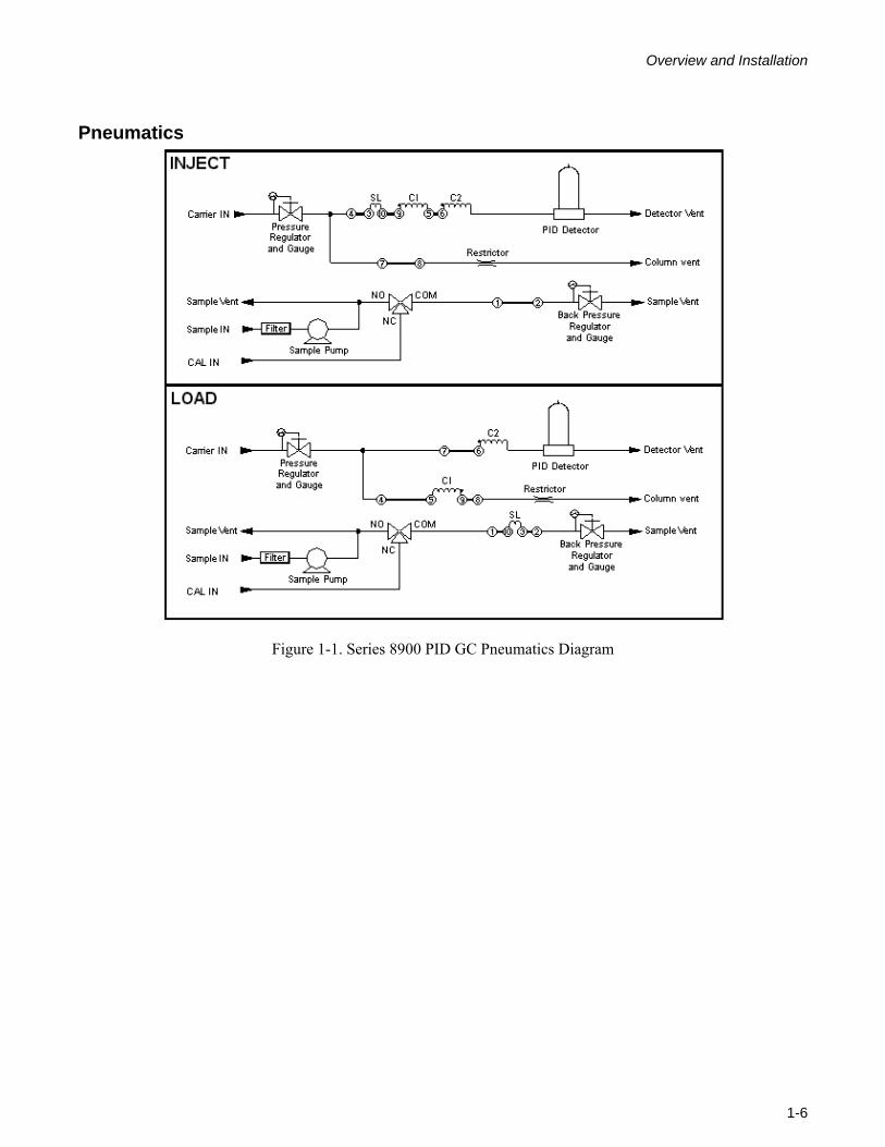
Analysis Theory The Series 8900 Gas Chromatograph is designed specifically for the analysis of many organic compounds some inorganic compounds. Refer to the appendix for a list of chemicals specific to your application. A single valve two column analytical arrangement is used (see figure 1-1). In one position (Inject) the two columns are in series with each other, the carrier stream enters column 1 (stripper Column - CI) then column 2 (analytical column - C2). In the other position (Load) the carrier stream is split into two streams. One leg reverses direction through column 1 to vent. The other continues through column 2 to the detector.
At sample injection a fixed volume sample is carried to the stripper column. Refer to the appendix for the volume of the fixed volume sample loop specific to your application. Back flush of the stripper column is timed from sample injection so that only the analytes of interest are eluted from the stripper column to the analytical column. The analytes of interest elute through the analytical column to the photo ionization detector (PID), while the other compounds are flushed to vent.
1-5
Overview and Installation
Pneumatics
Figure 1-1. Series 8900 PID GC Pneumatics Diagram
1-6
Overview and Installation
System Electronics - General Information
System Configurations All Series 8900 Gas Chromatographs are based on a modular, scalable electronics platform. Each system contains a power supply/distribution module, computer section and at least one detector support module.
All system electronic circuit cards are attached to the system data/control bus by stackable (through card) connectors. This allows the system components to be arranged in a variety of configurations.
The system electronics (Generation 3) are packaged in a manner that allows them to be replaced as modules (Power Supply, Main Board, CPU, Temperature Cards, Detector Support Cards, Digital to Analog Cards, Relay Cards, and Flow Cards).
Electrical Connections
Power The Series 8900 GC is designed to run off of standard 100 to 120 VAC 50/60Hz or 220 to 240 VAC 50/60Hz as specified in the appendix.
Communications Port 1 (COM 1) The Series 8900 Platform allows for method development, and instrument control or a simple ASCII TAB delimited protocol through communications port 1. When the instrument is operated in Stand Alone Mode (analyses are started from the instrument front panel), it will output a standard string of results at the end of each run. An external personal computer can acquire this analytical information from the analyzer using a standard terminal program. When the instrument is controlled with a personal computer running SkyChrom, communications port 1 is used for binary communication between SkyChrom and the 8900. See Section 5, Serial Communications for more information on Communications Port 1.
Example:
Stream TAB Port TAB Peak 1 TAB Concentration 1 TAB Peak 2 TAB Concentration 2 TAB Peak 3 TAB Concentration 3…
Or…
SAM P01 Benzene 0.025 Ethylbenzene 1.200 o-Xylene 0.362
Communications Port 2 (COM 2) The Series 8900 Platform allows for an optional second communications port, which can be used in conjunction with Motorola’s Moscad software to communicate certain operating parameters and concentration data. This software can be used to query analytical results and instrument status regardless of weather the instrument is being controlled by SkyChrom, or if it is in Stand Alone Mode. See Section 5, Serial Communications for more information on communications protocols for Communications Port 2.
1-7
Overview and Installation
Relays The Series 8900 PID GC is equipped with 5 standard relays. Optionally a relay board can be added to allow 15 total relays. A relay can be mapped to one of several internal events: trouble, port1, flow, flame, temperature, user, calibrate, bad calibration, caution, warning, and alarm. Relays have three attributes: the relay event mapping, the normal energy configuration, and the latch configuration. All relay attributes are assigned with SkyChrom software. The relays can be used as either contact closure (up to 7A @ 30VDC / RMS)
Note: For more information on Relays refer to the Method Relay Parameters Dialog in Section 7 of the SkyChrom manual.
Internal Events
TROUBLE Maps the trouble alarm event to the actuation of a relay
P1 Maps the selection of sample point 1 to the actuation of a relay
FLOW Maps the flow alarm event to the actuation of a relay, not used with a PID.
FLAME Maps the flameout alarm event to the actuation of a relay, not used with a PID.
TEMP Maps the temperature alarm event to the actuation of a relay
USER Makes the relay available for switching executing commands during an analysis. When a relay is set to User, it can be set and reset by the GC Program in the method.
CAL Maps a calibration event to the actuation of a relay
BAD CAL Maps a bad calibration event to the actuation of a relay
CAUT P1 Maps a caution level concentration from sample port 1 to the actuation of a relay
WARN P1 Maps a warning level concentration from sample port 1 to the actuation of a relay
ALRM P1 Maps an alarm level concentration from sample port 1 to the actuation of a relay
Relay Latching
The second attribute defines how a relay will perform once activated. A latched relay, once activated, persists until the user acknowledges the condition, regardless of whether or not the event that caused the activation continues to exist. A non-latched relay will persist until the event is no longer detected, at which point the relay resets automatically.
Relay Energization
The last attribute defines the normal, or inactive, condition of the relay. A normally energized relay will have power applied to its coil when it is not activated and vice versa. This gives the user an option of defining a relay to be active when the system is operating normally and if the power goes out the relay will change states.
DENRG This will set the relay to a normally de-energized state. When the relay is activated (set), it will become energized.
1-8
Overview and Installation
ENRG This will set the relay to a normally energized state. When the relay is activated (set), it will become de-energized.
Analog Outputs The Series 8900 PID-GC is equipped with 1 standard analog output. The G3 platform allows for a total of 5 analog outputs to be added to the main board, and 10 more to be added with an additional card. This allows a total of 15 analog outputs. Using SkyChrom the analog outputs can be programmed to output a linear output, a concentration output, or no output. Additionally the analog outputs can be programmed to either 0-20 mA or 4-20 mA.
NO OUT When not using the analog output, set to no output to free processor resources.
LIN OUT When Linear output is selected; the instrument will output a signal proportional to the detector current. This output can be sent to a strip chart recorder, reporting integrator, or a computer. This allows a chromatogram to be recorded.
CONC OUT When Concentration output is selected; the instrument will output a signal proportional to the concentration of the selected peak.
Note: For more information on Analog Outputs refer to the Method Analog Output Parameters Dialog in Section 7 of the SkyChrom manual.
Gas Connections A table is provided in the appendix of this manual that outlines the optimized pressures/flows for each gas port specific to your application.
SAMPLE IN The Sample stream is a continuously purged stream. This assures that when an analysis starts, the sample will be representative of the current conditions. This stream can be configured with or without a sample pump to allow pressurized samples or samples at or slightly below ambient pressures to be analyzed.
WARNING: The sample stream may be designed to draw samples at or near ambient pressures. Attaching a pressurized line to this type of sample inlet may cause permanent damage to the sample pump. Refer to the appendix for information on your unit’s specific configuration.
CAL IN
The Calibration stream is used to introduce calibration gas to the GC. The 8900 is designed to use a pressurized calibration gas. The pressure of the calibration gas delivered should be sufficiently higher than the sample backpressure setting to deliver adequate flow to purge the sample loop, but not excessively higher than the sample backpressure. Over pressurizing the calibration gas only wastes the calibration gas. Typically a flow of approximately 50-100 cc/min across the sample vent when the analytical stream is set to calibrate will completely purge the sample loop in a reasonable amount of time.
CARRIER IN
Depending on the application the type of carrier gas can vary. Typically the 8900 PID GC uses ultra pure Nitrogen or Helium as the
1-9
Overview and Installation
carrier gas. The linear velocity of the carrier in the column is manually controlled by adjusting the carrier adjust pressure regulator. Flows are balanced internally through the use of fritted restrictors. Refer to the appendix of this manual for the optimized pressure setting for your specific application. Typically, the pressure on the inlet should be 5-10 psi higher than the optimum carrier pressure so that the internal regulator can effectively “step down” the pressure and provide a constant flow through the columns. If using the carrier gas to actuate the analytical valve, set the inlet pressure to 60 psi, and use the carrier adjust knob to adjust the carrier pressure to the optimized value.
VALVE ACTUATE
This stream is used to actuate the analytical valve. Carrier gas or clean/dry air can be used. The inlet pressure for this line should be set to 60 psi to ensure proper valve switching.
SAMPLE VENT
The sample vent is used to vent the sample loop. If analyzing dangerous chemicals or high concentrations this vent should be routed to a safe location. Both calibration and sample gases will be vented through this port depending on which stream is selected. Do not pressurize this vent.
DETECTOR VENT
The detector vent is used to vent the detector. A photoionization detector is a non-destructive detector (the majority of the molecules remain effectively unchanged), so if analyzing dangerous chemicals or high concentrations this vent should be routed to a safe location. Do not pressurize this vent.
COLUMN VENT
The column vent is used to vent C1, the stripper column. Compounds that are more highly retained than the analytes of interest will be vented through this port. If the possibility of dangerous chemicals or concentrations exists, this vent should be routed to a safe location. Do not pressurize this line.
WARNING: Never attach a pressurized line to any of the instrument’s vents. Doing so may cause permanent damage to certain instrument components.
Installing the Analyzer
Unpacking 1. Remove the analyzer from the shipping box.
Inspect the pneumatic connections, front panel, and case, to verify that the instrument was received in good condition. The analyzer kit contains the following items:
• Series 8900 Gas Chromatograph
• User's Manual
• Power Cord
1-10
Overview and Installation
• Test report
• Null-Modem Cable
• Dongle
• SkyChrom installation CD
Be sure your kit is complete before proceeding.
2. Verify the serial and model number of the instrument.
Find the serial number tag (inside front door panel). Verify that the model number and serial number on the tag match those listed in the appendix. If they do not match, contact the factory before operating the analyzer.
3. Familiarize yourself with the front panel of the analyzer.
The front door panel features a vacuum fluorescent display, an on/off switch, and a four-button keypad. The display is used in conjunction with the keypad to operate the instrument and report analytical results.
4. Familiarize yourself with the back panel of the analyzer, the bottom panel for wall-mounts.
Gas ports and vents are located on the left side of the rear or bottom panel. Electrical connections are on the right.
A terminal strip is provided for signal connections and a power receptacle for AC power.
Installation Notes The following instructions will guide the user through installation of the analyzer.
1. Evaluate the installation site.
The analyzer has an operating temperature range of 32-104oF (0-40oC). Verify that the installation site will not exceed this range.
2. Verify that the installation site will provide sufficient clearance around the analyzer.
3. Locate all rear panel gas connections. Connect all gas lines as shown on your plumbing diagram.
A step-down regulator must be placed in pressurized gas streams to avoid damage to the instruments internal gas manifold. Refer to the gas pressures table (located in the appendix) to determine the correct inlet pressures for your analyzer.
Exhaust all vents at ambient pressure. Never attach a pressurized line to an analyzer vent. Doing so will damage the analyzer.
Depending on the application, and the toxicity of the sample gas or gases, all vents should be routed to a safe location. Flow rates and functions of vents are shown on the plumbing diagram.
4. Connect the signal and alarm wiring.
The terminal strip provides connections for signal and logic outputs that can interface with peripheral devices. These connections are documented in the appendix.
Note that the event mapping for each relay and the analog output parameters is defined using the SkyChrom software. (Refer to both this manual and the SkyChrom
1-11

Overview and Installation
manual Section 7, Method Relay Parameters Dialog, and Method Analog Output Parameters Dialog, for detailed instructions.)
3. Attach the AC power cord.
Verify the correct voltage by reading the label on the back for CE units ( or inside the flip down door of the 110V unit).
Once the installation is complete, proceed to Section 2 of this manual.
1-12
Section 2 – Instrument Operation User Interface
The Series 8900 Gas Chromatograph is a microprocessor-based instrument that can be controlled either by its internal system software, or with a PC and the use of SkyChrom. SkyChrom is used to develop methods and sequences, and then load the method or sequence into the instrument. Once a method has been installed, the 8900 can be run with a PC or without in a stand-alone mode. In most cases the 8900 has been pre-programmed with a factory-optimized method specific to the application. See the SkyChrom manual for information on developing methods and sequences.
WARNING: Be sure you have completed the installation procedure described in Section 1 of this manual prior to starting the analyzer. Improper installation of the analyzer can cause damage to the instrument, and potentially endanger the safety of the operator.
Description of the Front Panel Interface The front panel interface consists of an on/off switch, a vacuum fluorescent display, and a four-button keypad. The display is used in conjunction with the keypad to operate the system. It consists of two lines of alphanumeric characters that communicate analytical results, and provide the on-screen prompts necessary to guide you through the software menus.
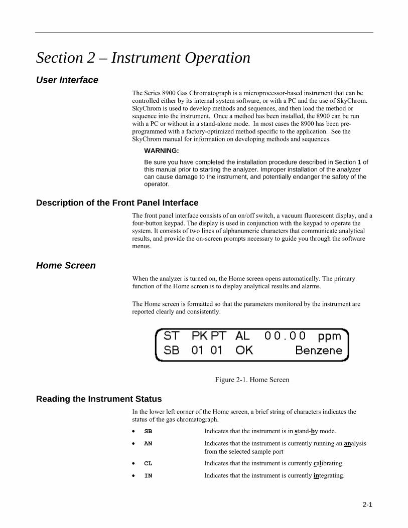
Home Screen When the analyzer is turned on, the Home screen opens automatically. The primary function of the Home screen is to display analytical results and alarms.
The Home screen is formatted so that the parameters monitored by the instrument are reported clearly and consistently.
Figure 2-1. Home Screen
Reading the Instrument Status In the lower left corner of the Home screen, a brief string of characters indicates the status of the gas chromatograph.
• SB Indicates that the instrument is in stand-by mode.
• AN Indicates that the instrument is currently running an analysis from the selected sample port
• CL Indicates that the instrument is currently calibrating.
• IN Indicates that the instrument is currently integrating.
2-1
Instrument Operation
Peak and Port Messages The analyzer reports the most recent concentrations for each peak and port in the Home screen. Under the PKPT area of the screen the instrument displays the current peak and port, 0201 refers to peak 2 from port 1. The right side of the display shows the most recent concentration and name of that peak. Pressing the button furthest to the right scrolls down the list, while pressing the furthest button to the left scrolls to the top of the list.
Alarm Messages Concentration alarm flags are displayed in the center of the screen, below the Prompt “AL.” If an alarm is active, a code indicating the alarm threshold violated will display directly below the port where the alarm was detected.
• OK Indicates no alarm status
• BC Indicates a bad calibration where one or more of the method’s recalibration thresholds have been exceeded
• C Indicates that one or more peak has exceeded the caution level
• W Indicates that one or more peak has exceeded the warning level.
• A Indicates that one or more peak has exceeded the alarm level
System alarm flags are displayed in the upper right of the screen. There are two types of system alarms, temperature and lamp. If “temp” is flashing in the upper right of the screen, this indicates that the temperature of the oven is more than 10% away from the set point. If “lamp” is flashing, this indicates that the lamp is not lit.
Buttons in the Home Screen The home screen can be in one of two states, Normal or Alarmed.
Home Screen in the Normal State When the Home screen is in the Normal state, there are no active concentration alarms.
In the Normal state, pressing either of the center two-keypad buttons opens the Options menu. The Options menu is a top-level menu that allows you to initiate one of three operational modes: Operations, Parameters or Information mode. These selections are detailed in the Options Menu subsection coming up.
Home Screen in the Alarmed State When the Home screen is in the Alarmed state, a concentration or system alarm is active.
2-2
Instrument Operation
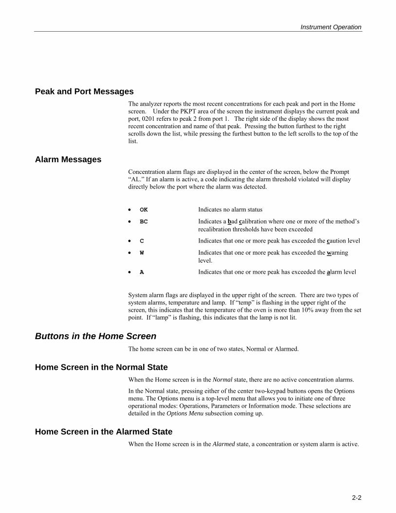
Whenever a concentration or system alarm is active, pressing one of the center two buttons in the Home screen brings up the Alarm Reset screen where the software prompts you to reset the active alarms. If you choose to reset, all active alarms are acknowledged.
Once a concentration alarm is acknowledged, the alarm code will stop flashing, and remain steadily lit. The alarm code will remain lit until the alarm condition no longer exists.
Note that if multiple alarm thresholds are violated on a given port, the software displays the alarm code associated with the highest alarm level violated. The software uses the concentration alarm hierarchy diagrammed below.
For example, if a sudden spike of the monitored substance was detected in the sample stream directed to port two, all alarm thresholds could be violated. In this case, the software would indicate the violations with the alarm code “A” indicating the highest alarm threshold violated in this incident. If you opt to reset the alarm, all alarm conditions would be acknowledged. Following a reset, the Home screen reopens.
R E S E T A AL R M S ?
< -< N O EY S - >
Figure 2-2. Reset Alarms Screen
Note: For more information on Alarms refer to the Method Concentration Alarm Parameters Dialog in Section 7 of the SkyChrom manual.
2-3
Instrument Operation
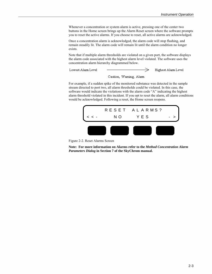
Software Structure The software receives its instructions from the front panel buttons. The function assigned to each front panel button is indicated by a button title displayed on-screen directly over the button. To navigate the software, press the front panel button corresponding to one of the selections displayed on-screen. If enabled in the method, each time a pressed button is detected the system will issue an audible beep. As you move through the software, the button titles will update to indicate the choices available at that point in the software. Button titles are called “soft” button titles because the software exclusively controls them.
Except for the Home screen, all screens in the software tree use soft button titles to communicate the options available to you at that point in the software.
Figure 2-3. Main Software Tree
2-4
Instrument Operation
Options Menu Selections in the Options menu allow you to initiate one of three modes: Operation, Parameters or Information mode.
OPR
Initiates the Operation Mode. In this mode the user can start various types of analyses, or initiate the manual mode.
• Start Analysis This command will be available if the instrument is in standby mode. If “Start Analysis” is selected, the instrument will run the assigned number of sample runs specified in the method. If this parameter is set to “0”, the instrument will run continuously.
Note: For more information on Methods see Creating a Method (Section 3) and Method Sheet (Section 7) in the SkyChrom manual.
• Stop Analysis This command will be available if the instrument is currently running a sample or calibration run. If “Stop Analysis” is selected, the instrument will stop the current run, integrate, and return to standby mode.
• Manual Mode When this command is selected, the manual mode will be initiated. For more information on the Manual Mode, see section 3.
• Calibrate Now When this command is selected, the instrument will initiate an unscheduled calibration run.
• Start Sequence Loop When this command is selected, the instrument will repeatedly run the loaded sequence until the “Stop Analysis” command is selected.
• Start Sequence When this command is selected, the instrument will run the loaded sequence one time.
Note: For more information on creating Sequences see Sequence Menu Commands (Section 5) and Sequence Settings Dialog (Section 7) in the SkyChrom manual.
Note: For more information on installing Sequences see Install Sequence Command (Instrument Menu) (Section 5) in the SkyChrom manual.
PARAM
Pressing this button will show the current oven temperature.
INFO
Initiates Information Mode where you can view system information.
2-5
Instrument Operation
Instrument Startup The steps documented in this subsection assume some familiarity with the operating software and interface. If you are not familiar with the Home screen, alarm prompts, and basic menu structure of the software, review the interface overview presented in the front of this section prior to startup.
Startup Instructions (Stand-alone operation) IMPORTANT WARNING: Be sure you have completed the installation procedure described in Section 1 of this manual prior to starting the analyzer. Improper installation of the analyzer can cause damage to the instrument, and potentially endanger the safety of the operator.
1. Turn on the carrier, calibration and sample gas flows to the instrument. Verify that the inlet pressures are adjusted correctly.
WARNING: Operating the analyzer without support gases may cause permanent damage to certain instrument components.
2. Press the I/O button on the front panel of the analyzer to turn on instrument.
A cursor appears in the upper left corner of the display to indicate that the startup sequence has been initiated. When the software initializes the software version is briefly reported on screen. Following this screen, the Warm Up screen opens.
3. The Warm Up screen will typically last for 15-20 minutes if the analyzer is cold. After the instrument is up to temperature the Home Screen will open.
4. Verify the operating temperature in the Temperature screen.
5. Verify the correct carrier pressure and sample pressure. Adjust to factory recommended pressures as described in the appendix (gas pressures) if necessary.
6. Calibrate the instrument. See Performing an Unscheduled Calibration.
7. Following calibration, the instrument is ready to run in stand-alone mode.
8. Select “Start Analysis” from the operations menu to start a stand-alone analysis.
When operating in Stand-alone mode, there are five options.
Single Analysis – The device will perform a single analysis, automatically stop the analysis, integrate the peaks, show the concentrations in the display, and output the data according to the loaded method. To set this mode the user should set the Run # parameter in the method to 1. For more information on methods see Section 3, Creating a Method in the SkyChrom manual.
N Analyses – The device will perform an analysis, integrate the peaks, show the concentrations in the display, output the data according to the loaded method, and start the next analysis. When the device completes N analyses (N is an integer), it will automatically stop. To set this mode the user should set the Run # parameter in the method to N.
Continuous Analyses – The device will perform an analysis, integrate the peaks, show the concentrations in the display, output the data according to the loaded method, and start the next run. The device will repeat these steps until the user selects the command OPER/STOP ANALYSIS?. To set this mode, the user should set the Run # parameter in the method to 0.
2-6
Instrument Operation
Start Sequence – In this mode, the instrument will perform the number of analyses and calibrations according to the loaded sequence and automatically stop. To start this mode, select the menu commands OPER/START SEQUENCE?. To stop a sequence before the end of the last analysis select the menu command OPER/STOP SEQUENCE?. Installing a new sequence does not change the current method, just as installing a new method does not change the current sequence.
Start Sequence Loop – In this mode, the instrument will perform the current sequence repeatedly until the menu command OPER/STOP SEQUENCE LOOP? is selected. To start this mode use the menu command OPER/START SEQUENCE LOOP?.
For each type of start, the instrument will perform the analog outputs (detector counts or concentration) according to the method settings. Once each analysis is complete and the peaks are integrated, the device will output the results through the COM1 port. An external PC using a standard terminal program can acquire this data.
Note: For more information on Methods see Creating a Method (Section 3) and Method Sheet (Section 7) in the SkyChrom manual.
Note: For more information on creating Sequences see Sequence Menu Commands (Section 5) and Sequence Settings Dialog (Section 7) in the SkyChrom manual.
Note: For more information on installing Sequences see Install Sequence Command (Instrument Menu) (Section 5) in the SkyChrom manual.
Startup Instructions (Operation with SkyChrom) See the SkyChrom manual for instructions on operating the 8900 PID GC using SkyChrom Software.
Startup Instructions (Start from Digital Input) See the SkyChrom manual Section 7 Method External Start Dialog for instructions on operating the 8900 PID GC using a digital input.
2-7
Instrument Operation
Performing an Unscheduled Calibration Follow the procedure below to perform an unscheduled calibration. These instructions assume the analyzer is properly connected to an appropriate source of calibration gas, and that the method is set up correctly to integrate the peaks.
1. From the Home screen, press one of the center two buttons to enter the options menu.
2. Press the key under OPR to enter the operations menu.
3. Scroll through the operations by pressing the arrow keys until “Calibrate Now” is displayed. Press the key under “Yes”
4. This initiates a calibration run.
5. Return to the home screen by repeatedly pressing the far left button.
6. In the home screen on the bottom left corner the instrument should display “CL”.
7. After the calibration run is finished the status indicator will briefly switch to “IN”, and then to “SB”. This indicates that the calibration is finished.
8. If the instrument calibrated correctly, and did not exceed any recalibration thresholds, the alarm status will read “OK”. The instrument is ready for stand-alone analysis. If the alarm status reports “BC”, for bad calibration, the instrument will automatically repeat a calibration run. If the second calibration run is successful, the instrument alarm status will display “OK”, if not, it will read “BC”. If after the second calibration the instrument still reports “BC” refer to the SkyChrom manual Section 3, Creating a Method.
2-8
Instrument Operation
Startup Trouble Shooting If the analyzer continues to display an alarm prompt after a reasonable warm-up period, follow the steps documented below for the active alarm.
TEMP Alarm Indicates that the unit has deviated from the current temperature setting.
1. Verify that the analyzer feels warm.
2. If the unit is warm, go into the Parameters mode and look at the current temperature reported in the "TEMPERATURE?" screen. The analyzer will initiate an alarm whenever the current temperature differs from the defined setup temperature (reported in the appendix of this manual) by more than 10%.
3. The current temperature and instrument settings can also be checked using the SkyChrom software package. Refer to the SkyChrom manual for instructions on How to… Check Instrument Settings (Section 4).
4. If the analyzer does not feel warm, call Baseline Technical Support for assistance.
LAMP Alarm Indicates that the PID lamp is not on.
1. Turn off the 8900 PID. Disconnect the power cord.
2. Remove the lamp cap located on the oven module.
3. Remove the lamp by lightly pulling on the plastic tubing connected to it’s top.
4. Inspect the lamp for any damage.
5. Re-insert the lamp. Make sure it “clicks into place”.
6. Plug in the power cord and re-start the instrument.
7. Allow the 8900 to come up to temperature.
8. If a lamp alarm persists, contact Baseline Technical Support for assistance.
2-9

Instrument Operation
Shutdown Message
1. Press the I/O button on the front panel.
The analyzer will briefly display a Shutdown screen. If this screen displays, the setup configurations have been successfully saved to memory. If the Shutdown screen does not display, edits made to the setup configurations since the last normal shutdown have not been saved.
Figure 2-4. Shutdown Screen
2-10
Instrument Operation
Power Switch Do’s and Don’ts
The 8900 is equipped with two power switches: the Standby/On button on the front panel, and a switch on the power entry module. In most situations the Standby/On button on the front panel should be used.
In the event that the 8900’s CPU locks up, it is equipped with a watchdog timer that will restart the unit after 40 seconds.
WARNING: After powering the 8900 down, wait a minimum of 30 seconds before re-starting the instrument. This allows all the internal voltages to drop to zero, and then start in the correct sequence to avoid damaging the CPU.
WARNING: Never service the unit while it is connected to an AC power outlet. Before accessing any internal components unplug the power cord from the power inlet module.
2-11
Instrument Operation
Accidental Power Loss
In the event of an accidental power loss the 8900 is equipped with several features, these features vary depending upon how the instrument was started.
While in Stand Alone Mode If the 8900 looses power while in Stand Alone Mode the action that the instrument takes depends upon the Run # parameter in the GC Program tab of the method, or if it is running a sequence or not. See the SkyChrom manual Section 7, Method GC Program Dialog.
0 = Run #
When the Run # is set to 0 this sets the instrument to a continuous run mode. In the event of accidental power loss while the instrument is in this mode, when power returns, the 8900 will automatically re-start, warm-up, and begin analyzing in a continuous mode.
1…n =Run #
When the Run # is set to some integer, the 8900 runs a number of analyses equal to that integer and then returns to the stand-by mode. In the event of accidental power loss while the instrument is in this mode, when power returns, the 8900 will automatically re-start, warm-up, and enter the stand-by mode.
While Running a Sequence
While running a loaded Sequence the instrument runs the specified runs from the loaded Sequence and then returns to stand-by mode. In the event of accidental power loss while the instrument is in this mode, when power returns, the 8900 will automatically re-start, warm-up, and enter the stand-by mode.
While Running a Sequence Loop
While running a Sequence Loop, the instrument repeatedly runs the Sequence. In the event of accidental power loss while the instrument is in this mode, when power returns, the 8900 will automatically re-start, warm-up, and automatically restart the loaded sequence from the beginning.
When Controlled by SkyChrom If the 8900 looses power while being controlled by SkyChrom, the action the instrument takes depends first upon if the PC controlling it looses power, and second, upon which mode SkyChrom is controlling the instrument. The action taken by the 8900 in this case is independent from the Run# in the method, but instead totally dependant upon whether the current run was a single analysis, analysis sequence, or analysis sequence loop.
Single Analysis
When SkyChrom is running a single analysis, the 8900 runs the specified number of runs set by the Run # parameter in the GC Program tab of the Method, and returns to stand-by mode. In the event of an accidental power loss (pending the PC does not loose power),
2-12
Instrument Operation
SkyChrom will remain open, showing a partial chromatogram. When power returns to the instrument the instrument will automatically re-start, warm up, and enter the stand-by mode. Clicking on the stop button in SkyChrom will allow a single analysis to be re-started.
Analysis Sequence
When SkyChrom is running an analysis sequence, the 8900 runs the specified sub-sequences, and then returns to the stand-by mode. In the event of accidental power loss (pending the PC does not loose power), SkyChrom will remain open, showing a partial chromatogram. When power returns to the instrument the instrument will automatically restart, warm up, and enter the stand-by mode. Clicking on the stop button in SkyChrom will allow the sequence to be re-started.
Analysis Sequence Loop
When SkyChrom is running an analysis sequence loop, the 8900 runs the current sequence repeatedly. In the event of accidental power loss (pending the PC does not loose power), SkyChrom will remain open. In this case, SkyChrom will timeout, and wait until the 8900 is in the stand-by mode. When power returns, the 8900 will automatically restart, warm up, and enter the stand-by mode. After the 8900 enters the stand-by mode, SkyChrom will automatically restart the sequence from the beginning. When SkyChrom restarts the sequence it also resets the analysis run count. If saving all chromatograms, this shows the user the time and duration of power outages.
Lamp Cleaning Procedure
The following instructions are intended for use with a Baseline lamp cleaning kit (dry method), Baseline part # YPO52004.
- Turn off the instrument and unplug the power cord.
- Remove the lamp from the instrument by gently pulling on the small piece of tubing attached to the end.
- Place the gray cleaning pad on a smooth dry surface (there is no need to remove the backing from the pad).
- Place the lens of the lamp flat on the pad. It is critical to keep the entire lens surface in contact with the pad during the cleaning process.
- While applying gentle downward pressure, move the lamp in a circular motion on the pad. (Complete 5-10 1 inch circles in a localized area of the pad)
- Lift the lamp off the pad and wipe any residue away on the provided felt pad.
- Reinsert the lamp in the instrument by applying gentle inward pressure to the tube attached to the end until you feel the lamp “click” into place.
- After cleaning and reinserting the lamp, allow the instrument to run for approximately one hour and recalibrate the instrument before use. This time will allow the instrument to equilibrate to the newly cleaned lamp.
- Each cleaning pad included in the cleaning kit may be used for 4-5 cleanings. The felt pad may be used 30-40 times.
2-13
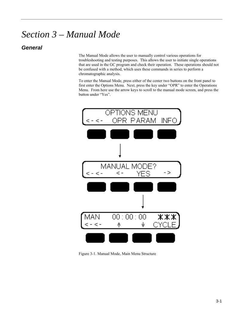
Section 3 – Manual Mode General
The Manual Mode allows the user to manually control various operations for troubleshooting and testing purposes. This allows the user to initiate single operations that are used in the GC program and check their operation. These operations should not be confused with a method, which uses these commands in series to perform a chromatographic analysis.
To enter the Manual Mode, press either of the center two buttons on the front panel to first enter the Options Menu. Next, press the key under “OPR” to enter the Operations Menu. From here use the arrow keys to scroll to the manual mode screen, and press the button under “Yes”.
Figure 3-1. Manual Mode, Main Menu Structure
3-1
Manual Mode
Options Once in Manual mode pressing the keys under ↑ or ↓ will scroll through a list of commands. The top line of the menu indicates that the manual mode is active, shows the program clock and the last executed command. The program timer in the manual mode is reset to 00:00:00 when the CYCLE command is executed, and is started when any other command is executed.
Manual Mode Commands
• CYCLE Resets the program counter, when executed from a method this command will also start then next analysis, typically not used in manual mode
• HALT Halt the program, typically not used in manual mode
• BLA_01 Baseline adjust analog signal 1 (adds offset to attain desired % FS baseline)
• CBLA_01 Clear baseline adjust from analog signal 1 (removes offset from analog signal 1 baseline)
• AT1_00 Sets the attenuation on analog output 1 to 20
• AT1_01 Sets the attenuation on analog output 1 to 21
• AT1_02 Sets the attenuation on analog output 1 to 22
• AT1_03 Sets the attenuation on analog output 1 to 23
• AT1_04 Sets the attenuation on analog output 1 to 24
• AT1_05 Sets the attenuation on analog output 1 to 25
• AT1_06 Sets the attenuation on analog output 1 to 26
• AT1_07 Sets the attenuation on analog output 1 to 27
• AT1_08 Sets the attenuation on analog output 1 to 28
• AT1_09 Sets the attenuation on analog output 1 to 29
• AT1_10 Sets the attenuation on analog output 1 to 210
• BLA_02 Baseline adjust analog signal 2 (adds offset to attain desired % FS baseline)
• CBLA_02 Clear baseline adjust from analog signal 2 (removes offset from analog signal 1 baseline)
• AT2_00 Sets the attenuation on analog output 2 to 20
• AT2_01 Sets the attenuation on analog output 2 to 21
• AT2_02 Sets the attenuation on analog output 2 to 22
• AT2_03 Sets the attenuation on analog output 2 to 23
• AT2_04 Sets the attenuation on analog output 2 to 24
• AT2_05 Sets the attenuation on analog output 2 to 25
• AT2_06 Sets the attenuation on analog output 2 to 26
3-2

Manual Mode
• AT2_07 Sets the attenuation on analog output 2 to 27
• AT2_08 Sets the attenuation on analog output 2 to 28
• AT2_09 Sets the attenuation on analog output 2 to 29
• AT2_10 Sets the attenuation on analog output 2 to 210
• RESET Reset all active signals (valves, relays, etc…)
• INJ_1 Actuates the analytical valve to the inject position
• INJ_2 Turns valve 2 on (optional)
• LOAD_1 Actuates the analytical valve to the load position
• LOAD_2 Turns valve 2 off (optional)
• Gain_L Sets the electrometer gain to low
• Gain_M Sets the electrometer gain to medium
• Gain_H Sets the electrometer gain to high
• SS_ 01 Set signal 1 (activate relay 1)
• SS_ 02 Set signal 2 (activate relay 2)
• SS_ 03 Set signal 3 (activate relay 3)
• SS_ 04 Set signal 4 (activate relay 4)
• SS_ 05 Set signal 5 (activate relay 5)
• SS_ 06 Not used
• RS_ 01 Reset signal 1 (deactivate relay 1)
• RS_ 02 Reset signal 2 (deactivate relay 2)
• RS_ 03 Reset signal 3 (deactivate relay 3)
• RS_ 04 Reset signal 4 (deactivate relay 4)
• RS_ 05 Reset signal 5 (deactivate relay 5)
• RS_ 06 Not used
3-3

Section 4 – Information Mode General
The Information Mode allows the user to view system information.
The user can easily view this information by navigating through the information features diagramed in figure 5-1.
Figure 4-1. Information Mode, Main Menu Structure
4-1
Information Mode
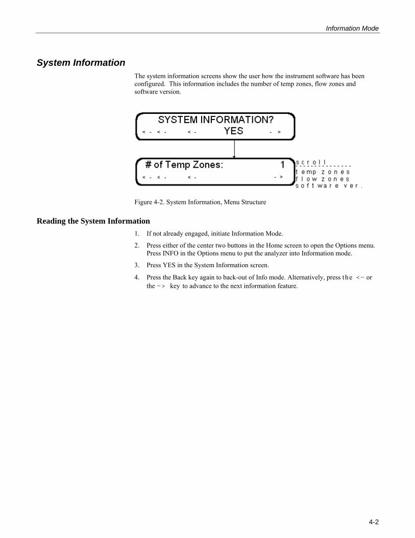
System Information The system information screens show the user how the instrument software has been configured. This information includes the number of temp zones, flow zones and software version.
Figure 4-2. System Information, Menu Structure
Reading the System Information 1. If not already engaged, initiate Information Mode.
2. Press either of the center two buttons in the Home screen to open the Options menu. Press INFO in the Options menu to put the analyzer into Information mode.
3. Press YES in the System Information screen.
4. Press the Back key again to back-out of Info mode. Alternatively, press the <- or the -> key to advance to the next information feature.
4-2
Section 5 – Serial Communications General Information
The Series 8900 GC when in Stand Alone Mode (started from the front panel) ships operating parameters and concentration data through communications port 1 (COM 1). This is done through a simple ASCII TAB delimited protocol. An external personal computer can acquire this analytical information from the analyzer using a standard terminal program. The 8900 GC can be optionally equipped with a second communications port (COM 2). During normal operation, analytical results and instrument status can be queried from the analyzer according to the Motorola Moscad application protocol.
Data Shipped by the Analyzer (COM 1) When in Stand Alone Mode, the analyzer ships the following data fields (TAB delimited) once after each analysis.
• Stream
• Port
• Concentration (ppm) For each peak
See also Communications Port 1 (COM 1) in Section 1 for more information on communications port 1.
Commands accepted by the analyzer. (COM 1)
For information about digital commands accepted by the analyzer, please contact the factory.
Communications framing parameters (COM 1) The Series 800 Analyzer sends a set of ASCII data after every sample run. The data set is TAB delimited and terminated by a carriage return and line feed. Communication parameters are as follows:
• Baud Rate = 9600
• Data Bits = 8
• Stop Bit = 1
• Parity – NO Parity
• DTR control – Not used
• Xon/Xof Control – Not used
• RTS Control – Used. After starting the chromatograph, for the first 20 … 40 seconds, it is disabled. After this it is enabled.
5-1
Serial Communications
Explanation of data fields (COM 1)
Stream Tells which stream (Sample – SAM, Calibration – CAL, or Inject – INJ, Not used for PID) the current analysis was performed on.
Port Contains the current port number (if from the sample stream). For single port units this will always be P01.
Concentration. Contains the current concentration for each calibrated peak in the analysis in order of increasing retention time. This concentration is reported in units of ppm (parts per million).
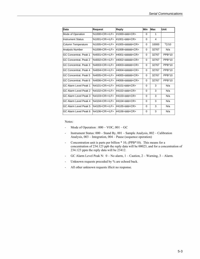
Com 2 Protocol - For each request the instrument will recognize 7 bytes. The 8900 will accept the last
two bytes in any order: Carriage Return, <CR> and Line Feed, <LF>. For example: %1000<CR><LF> or %1000<LF><CR> are both valid requests.
- For each reply the 8900 GC will reply with either 10 or 12 bytes. For example the reply for instrument status is 10 bytes, while the reply for the column temperature is 12 bytes.
- The 8900 GC can support up to 29 peaks with this type of communication.
5-2
Serial Communications
Data Request Reply Min Max Unit
Mode of Operation %1000<CR><LF> #1000=ddd<CR> 0 1
Instrument Status %1001<CR><LF> #1001=ddd<CR> 0 4
Column Temperature %1005<CR><LF> #1005=ddddd<CR> 0 10000 oC/10
Analysis Number %1008<CR><LF> #1008=ddddd<CR> 0 32767 N/a
GC Concentrat. Peak 1 %4001<CR><LF> #4001=ddddd<CR> 0 32767 PPB*10
GC Concentrat. Peak 2 %4002<CR><LF> #4002=ddddd<CR> 0 32767 PPB*10
GC Concentrat. Peak 3 %4003<CR><LF> #4003=ddddd<CR> 0 32767 PPB*10
GC Concentrat. Peak 4 %4004<CR><LF> #4004=ddddd<CR> 0 32767 PPB*10
GC Concentrat. Peak 5 %4005<CR><LF> #4005=ddddd<CR> 0 32767 PPB*10
GC Concentrat. Peak 6 %4006<CR><LF> #4006=ddddd<CR> 0 32767 PPB*10
GC Alarm Level Peak 1 %4101<CR><LF> #4101=ddd<CR> 0 3 N/a
GC Alarm Level Peak 2 %4102<CR><LF> #4102=ddd<CR> 0 3 N/a
GC Alarm Level Peak 3 %4103<CR><LF> #4103=ddd<CR> 0 3 N/a
GC Alarm Level Peak 4 %4104<CR><LF> #4104=ddd<CR> 0 3 N/a
GC Alarm Level Peak 5 %4105<CR><LF> #4105=ddd<CR> 0 3 N/a
GC Alarm Level Peak 6 %4106<CR><LF> #4106=ddd<CR> 0 3 N/a
Notes:
- Mode of Operation : 000 – VOC, 001 – GC
- Instrument Status: 000 – Stand By, 001 – Sample Analysis, 002 – Calibration Analysis, 003 – Integration, 004 – Pause (sequence operation)
- Concentration unit is parts per billion * 10, (PPB*10). This means for a concentration of 234.123 ppb the reply data will be 00023, and for a concentration of 234.123 ppm the reply data will be 23412.
- GC Alarm Level Peak N: 0 – No alarm, 1 – Caution, 2 – Warning, 3 – Alarm.
- Unknown requests preceded by % are echoed back.
- All other unknown requests illicit no response.
5-3