Embed Size (px)
Citation preview
Series 905-OV10
CAN/CANopen DC Output Module
Installation and Operating Manual
Model 905-OV10 DC Output Module. -Page 2- Operations Manual
Smart Electronics Rev 120523
Document Revisions
120523 Corrected PDO to 512+NODE ID in “
11217 Corrected hint after object 6300H detail.
10324 Object 2015 eliminated from object table.
Operating without CANopen master section updated.
Typographical corrections.
91201 Original document with graphics.

Model 905-OV10 DC Output Module. -Page 3- Operations Manual
Smart Electronics Rev 120523
Table of Contents
Module Installation Procedure ................................................................................................................................ 5 Power and Output Connections .............................................................................................................................. 5 DIP Switch Settings ................................................................................................................................................ 5
Setting the Baud Rate.......................................................................................................................................... 6 Setting the Node ID ............................................................................................................................................ 6
Operating Without a CANopen Master .................................................................................................................. 7 CANopen Object Dictionary................................................................................................................................... 8
Object Dictionary Details ................................................................................................................................. 10
1400H Receive PDO Communication Parameters.................................................................................. 10 1600H Receive PDO Mapping Parameter ............................................................................................... 10 6300H Write output ................................................................................................................................... 11 6302H Polarity output ............................................................................................................................... 12
6306H Error mode output ......................................................................................................................... 12 6307H Error value output ......................................................................................................................... 13 6308H Filter mask output ......................................................................................................................... 13
2021H Output command PDO echo control ............................................................................................ 13
Hardware Specifications ....................................................................................................................................... 13 905-OV10 Output Characteristic Graphs .............................................................................................................. 16
Guidelines for Supplying Power to the I/O Modules............................................................................................ 17
Equivalent Circuit ................................................................................................................................................. 18
Typical Application Connections ......................................................................................................................... 19 Network Terminator.............................................................................................................................................. 20
LED Indicators ...................................................................................................................................................... 21 Diagnostic Status Flash Codes .......................................................................................................................... 21
Node Guarding Reference ..................................................................................................................................... 23
Life Guarding Reference....................................................................................................................................... 24 Appendix ............................................................................................................................................................... 25
CAN Network Wiring Reference...................................................................................................................... 25 Table A1. DIP Switch Setting for Node ID 1-63 ............................................................................................. 26
Table A1. DIP Switch Setting for Node Id 64-127 .......................................................................................... 27 Mounting Dimensions ........................................................................................................................................... 28

Model 905-OV10 DC Output Module. -Page 4- Operations Manual
Smart Electronics Rev 120523
21 5 643 1087 9
Model 905-OV10
Series 905 modules are compact panel mount 24V DC I/O modules with integrated CAN/CANopen network
communications.
Model 905-OV10 is a 10-channel, solid state current sinking output module with internal overload protection.
For a complete discussion about the CANopen network protocol, please refer to CiA documents DS301 and
DS401 available at http://www.smartelectronics.ca/canopenio.htm and at CiA.org. The Series 905 modules can
be easily integrated into a PLC based control system having a CANopen network adapter. It can also be easily
integrated into custom OEM based PC or embedded microcontroller/microprocessor based control systems that
use only the CAN network capabilities of the module and have a proprietary logic or communication protocol
standard. The model 905-OV10 outputs can be controlled by transmitting few simple CAN packets to the
module.
Note. The Series 905 modules implement many of the most commonly used and important
features of the CANopen protocol, but do increase response speed and efficiency and to
reduce costs it does not implement the entire protocol. Refer to the object dictionary section
for more details.
Model 905-OV10 DC Output Module. -Page 5- Operations Manual
Smart Electronics Rev 120523
Module Installation Procedure
Install the module on to a secure surface using the mounting holes on either end of the module.
Set the baud rate and node address using the DIP switch.
Connect 12-24 VDC module power to the V+ and GND terminals.
Connect a CAN network cable to the CANH, CANL, GND and/or SHLD terminals.
Use a CANopen configuration tool to change the modules operating parameters via the object
dictionary.
Test the module communication over a functioning CAN network
Note. When connecting a module to a CAN network with other devices it is often necessary
to daisy chain the CANL, CANH, and or GND/SHLD wiring. Two wires can be inserted into
each module terminal if the wires are AWG 22 or smaller. Power and Output Connections
Connect the DC control power supply to the terminals marked 24 IN and 0V IN at the top and bottom of the
output terminal strip. For maximum reliability the output power supply should be a separate unit from the one
powering the module and the CAN interface (V+ and V- terminals).
Connect output devices to the output terminals. The 24V common is available to each device to reduce wiring:
typically one wire from a dc solenoid, lamp, or other load connects to the terminal marked 24 and the other wire
connects to the adjacent output terminal marked 1 though 10.
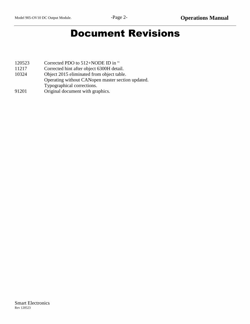
DIP Switch Settings
The CAN network baud rate and node number is set using the DIP switch visible on the I/O module. This DIP
switch has 10 individual switches; switches marked 1-3 set the baud rate, and switches marked 4-10 set the
node identifier (or node number).
As an example, the DIP switch at left
configures the I/O module node 1
communication at 500 KHz.
This is the default configuration.
Model 905-OV10 DC Output Module. -Page 6- Operations Manual
Smart Electronics Rev 120523
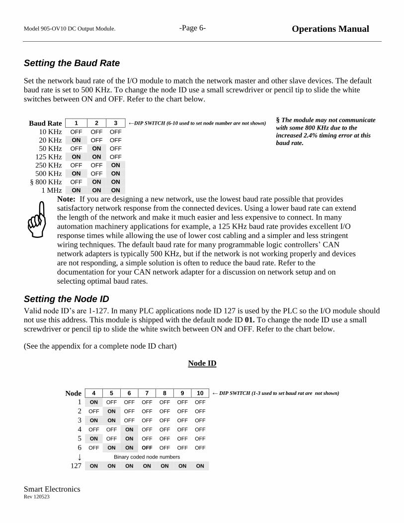
Setting the Baud Rate
Set the network baud rate of the I/O module to match the network master and other slave devices. The default
baud rate is set to 500 KHz. To change the node ID use a small screwdriver or pencil tip to slide the white
switches between ON and OFF. Refer to the chart below.
§ The module may not communicate
with some 800 KHz due to the
increased 2.4% timing error at this
baud rate.
Note: If you are designing a new network, use the lowest baud rate possible that provides
satisfactory network response from the connected devices. Using a lower baud rate can extend
the length of the network and make it much easier and less expensive to connect. In many
automation machinery applications for example, a 125 KHz baud rate provides excellent I/O
response times while allowing the use of lower cost cabling and a simpler and less stringent
wiring techniques. The default baud rate for many programmable logic controllers’ CAN
network adapters is typically 500 KHz, but if the network is not working properly and devices
are not responding, a simple solution is often to reduce the baud rate. Refer to the
documentation for your CAN network adapter for a discussion on network setup and on
selecting optimal baud rates. Setting the Node ID
Valid node ID’s are 1-127. In many PLC applications node ID 127 is used by the PLC so the I/O module should
not use this address. This module is shipped with the default node ID 01. To change the node ID use a small
screwdriver or pencil tip to slide the white switch between ON and OFF. Refer to the chart below.
(See the appendix for a complete node ID chart)
Node ID
Baud Rate 1 2 3 ←DIP SWITCH (6-10 used to set node number are not shown)
10 KHz OFF OFF OFF
20 KHz ON OFF OFF
50 KHz OFF ON OFF
125 KHz ON ON OFF
250 KHz OFF OFF ON
500 KHz ON OFF ON
§ 800 KHz OFF ON ON
1 MHz ON ON ON
Node 4 5 6 7 8 9 10 ← DIP SWITCH (1-3 used to set baud rat are not shown)
1 ON OFF OFF OFF OFF OFF OFF 2 OFF ON OFF OFF OFF OFF OFF 3 ON ON OFF OFF OFF OFF OFF 4 OFF OFF ON OFF OFF OFF OFF 5 ON OFF ON OFF OFF OFF OFF 6 OFF ON ON OFF OFF OFF OFF ↓ Binary coded node numbers
127 ON ON ON ON ON ON ON
Model 905-OV10 DC Output Module. -Page 7- Operations Manual
Smart Electronics Rev 120523
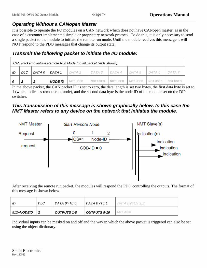
Operating Without a CANopen Master
It is possible to operate the I/O modules on a CAN network which does not have CANopen master, as in the
case of a customer implemented simple or proprietary network protocol. To do this, it is only necessary to send
a single packet to the module to initiate the remote run mode. Until the module receives this message it will
NOT respond to the PDO messages that change its output state.
Transmit the following packet to initiate the I/O module:
CAN Packet to Initiate Remote Run Mode (no all packet fields shown).
ID DLC DATA 0 DATA 1 DATA 2 DATA 3 DATA 4 DATA 5 DATA 6 DATA 7
0 2 1 NODE ID NOT USED NOT USED NOT USED NOT USED NOT USED NOT USED
In the above packet, the CAN packet ID is set to zero, the data length is set two bytes, the first data byte is set to
1 (which indicates remote run mode), and the second data byte is the node ID of the module set on the DIP
switches.
This transmission of this message is shown graphically below. In this case the NMT Master refers to any device on the network that initiates the module.
After receiving the remote run packet, the modules will respond the PDO controlling the outputs. The format of
this message is shown below.
ID DLC DATA BYTE 0 DATA BYTE 1 DATA BYTES 2..7
512+NODEID 2 OUTPUTS 1-8 OUTPUTS 9-10 NOT USED
Individual inputs can be masked on and off and the way in which the above packet is triggered can also be set
using the object dictionary.
Model 905-OV10 DC Output Module. -Page 8- Operations Manual
Smart Electronics Rev 120523
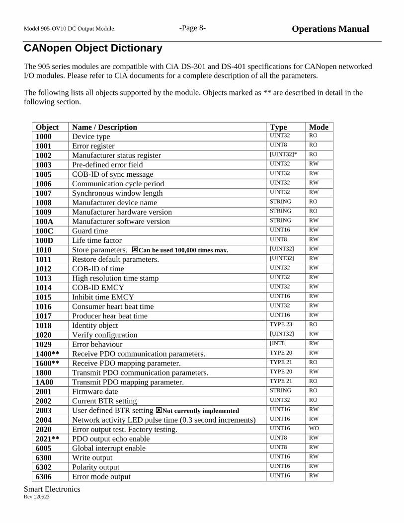
CANopen Object Dictionary
The 905 series modules are compatible with CiA DS-301 and DS-401 specifications for CANopen networked
I/O modules. Please refer to CiA documents for a complete description of all the parameters.
The following lists all objects supported by the module. Objects marked as ** are described in detail in the
following section.
Object Name / Description Type Mode
1000 Device type UINT32 RO
1001 Error register UINT8 RO
1002 Manufacturer status register [UINT32]* RO
1003 Pre-defined error field UINT32 RW
1005 COB-ID of sync message UINT32 RW
1006 Communication cycle period UINT32 RW
1007 Synchronous window length UINT32 RW
1008 Manufacturer device name STRING RO
1009 Manufacturer hardware version STRING RO
100A Manufacturer software version STRING RW
100C Guard time UINT16 RW
100D Life time factor UINT8 RW
1010 Store parameters. Can be used 100,000 times max. [UINT32] RW
1011 Restore default parameters. [UINT32] RW
1012 COB-ID of time UINT32 RW
1013 High resolution time stamp UINT32 RW
1014 COB-ID EMCY UINT32 RW
1015 Inhibit time EMCY UINT16 RW
1016 Consumer heart beat time UINT32 RW
1017 Producer hear beat time UINT16 RW
1018 Identity object TYPE 23 RO
1020 Verify configuration [UINT32] RW
1029 Error behaviour [INT8] RW
1400** Receive PDO communication parameters. TYPE 20 RW
1600** Receive PDO mapping parameter. TYPE 21 RO
1800 Transmit PDO communication parameters. TYPE 20 RW
1A00 Transmit PDO mapping parameter. TYPE 21 RO
2001 Firmware date STRING RO
2002 Current BTR setting UINT32 RO
2003 User defined BTR setting Not currently implemented UINT16 RW
2004 Network activity LED pulse time (0.3 second increments) UINT16 RW
2020 Error output test. Factory testing. UINT16 WO
2021** PDO output echo enable UINT8 RW
6005 Global interrupt enable UINT8 RW
6300 Write output UINT16 RW
6302 Polarity output UINT16 RW
6306 Error mode output UINT16 RW

Model 905-OV10 DC Output Module. -Page 9- Operations Manual
Smart Electronics Rev 120523
Object Name / Description Type Mode
6307 Error value output UINT16 RW
6308 Filter mask output UINT16 RW
Notes:
[] Square brackets denote array value
UINT8 unsigned 8 bit integer
UINT16 unsigned 16 bit integer
UINT32 unsigned 32 bit integer
RO Read Only
RW Read and Write object
WO Write Object Only
Model 905-OV10 DC Output Module. -Page 10- Operations Manual
Smart Electronics Rev 120523
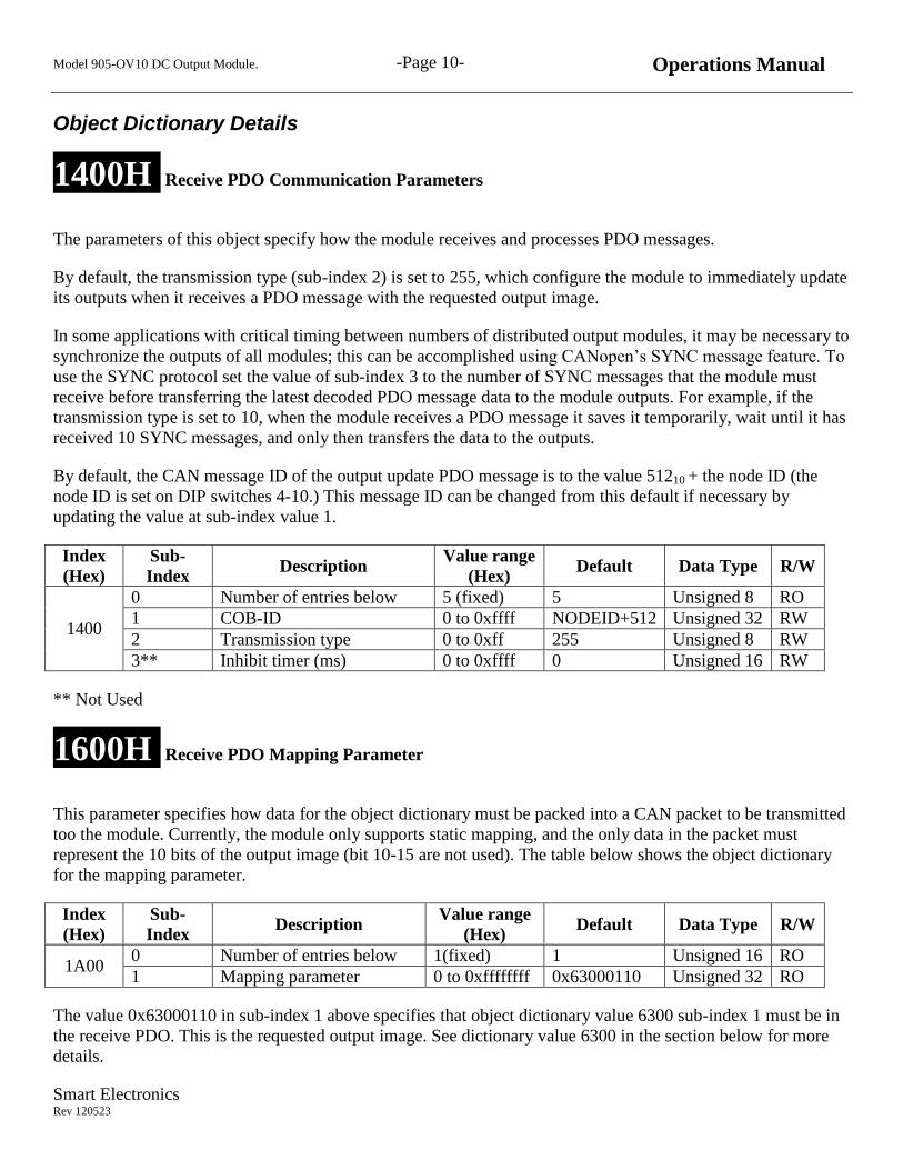
Object Dictionary Details
1400H Receive PDO Communication Parameters
The parameters of this object specify how the module receives and processes PDO messages.
By default, the transmission type (sub-index 2) is set to 255, which configure the module to immediately update
its outputs when it receives a PDO message with the requested output image.
In some applications with critical timing between numbers of distributed output modules, it may be necessary to
synchronize the outputs of all modules; this can be accomplished using CANopen’s SYNC message feature. To
use the SYNC protocol set the value of sub-index 3 to the number of SYNC messages that the module must
receive before transferring the latest decoded PDO message data to the module outputs. For example, if the
transmission type is set to 10, when the module receives a PDO message it saves it temporarily, wait until it has
received 10 SYNC messages, and only then transfers the data to the outputs.
By default, the CAN message ID of the output update PDO message is to the value 51210 + the node ID (the
node ID is set on DIP switches 4-10.) This message ID can be changed from this default if necessary by
updating the value at sub-index value 1.
Index
(Hex)
Sub-
Index Description
Value range
(Hex) Default Data Type R/W
1400
0 Number of entries below 5 (fixed) 5 Unsigned 8 RO
1 COB-ID 0 to 0xffff NODEID+512 Unsigned 32 RW
2 Transmission type 0 to 0xff 255 Unsigned 8 RW
3** Inhibit timer (ms) 0 to 0xffff 0 Unsigned 16 RW
** Not Used
1600H Receive PDO Mapping Parameter
This parameter specifies how data for the object dictionary must be packed into a CAN packet to be transmitted
too the module. Currently, the module only supports static mapping, and the only data in the packet must
represent the 10 bits of the output image (bit 10-15 are not used). The table below shows the object dictionary
for the mapping parameter.
Index
(Hex)
Sub-
Index Description
Value range
(Hex) Default Data Type R/W
1A00 0 Number of entries below 1(fixed) 1 Unsigned 16 RO
1 Mapping parameter 0 to 0xffffffff 0x63000110 Unsigned 32 RO
The value 0x63000110 in sub-index 1 above specifies that object dictionary value 6300 sub-index 1 must be in
the receive PDO. This is the requested output image. See dictionary value 6300 in the section below for more
details.

Model 905-OV10 DC Output Module. -Page 11- Operations Manual
Smart Electronics Rev 120523
Layout of Static Object Dictionary Map to CAN packet
The module signals the status of the outputs by transmitting a “PDO” message on the CAN network.
The ID of this message is 512+NODE ID and the DLC is 2.
The layout of the data portion of the CAN packet is shown below.
Receive RPDO1 (Length 2 Bytes)
Byte 0 1 2 3 4 5 6 7
OUT7-
OUT0
OUT9-
OUT8
Not Used Not Used Not Used Not Used Not Used Not Used
Detail of Data Input Bytes RPDO1
BYTE 0 BYTE 1
7 6 5 4 3 2 1 0 7 6 5 4 3 2 1 0 OUT
8
OUT
7
OUT
6
OUT
5
OUT
4
OUT
3
OUT
2 OUT
1 x x x x x x OUT
10
OUT
9
OUT 0-OUT 9 translates to the 10 terminals marked 1-10 on the module.
Note:
DS-301 specifies that SDO and PDO data is mapped to the CAN packet in “little endian” form.
Hint: If your network does not have a CANopen master, and you are implementing a simple
or proprietary network, you can use the above map to encode the output image request. 6300H Write output
This object holds the output image and each bit in the 16-bit word at sub-index 1 corresponds to one of the 10
output terminals. Bit 0 corresponds to output 1, bit 1 to output 2, and so on to output 10. Bits 10-15 are not used.
To turn an output ON, set the corresponding bit in the output image to 1. In the default mode, the change is
immediate.
In most circumstances, an operating network will not control the outputs by writing directly to the object
dictionary using SDO messages, but rather by sending PDO messages to the module. PDO messages are faster
and require less over-head to implement.
Index
(Hex) Sub-Index Description
Value range
(Hex) Default Data Type R/W
6100 0 Number of entries below 1 1 Unsigned 16 RO
1 Output1-16 (see below) 0 to 0xffff - Unsigned 16 RO
Model 905-OV10 DC Output Module. -Page 12- Operations Manual
Smart Electronics Rev 120523
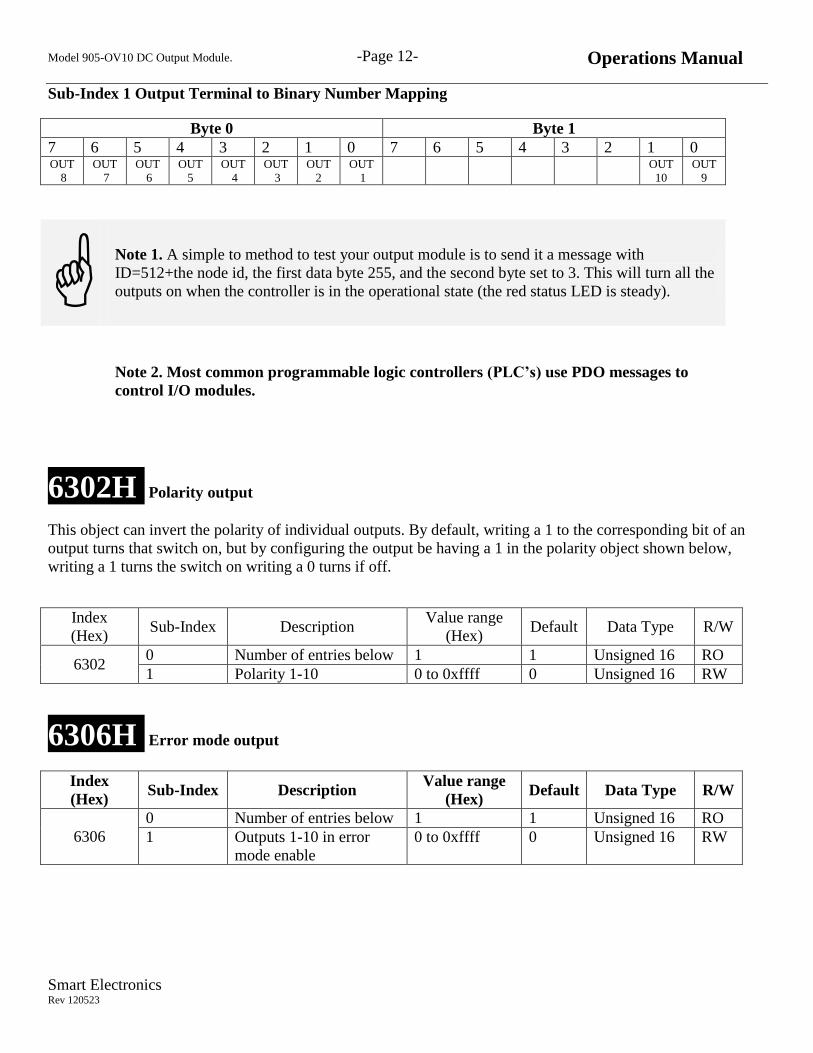
Sub-Index 1 Output Terminal to Binary Number Mapping
Byte 0 Byte 1
7 6 5 4 3 2 1 0 7 6 5 4 3 2 1 0 OUT
8
OUT
7
OUT
6
OUT
5
OUT
4
OUT
3
OUT
2 OUT
1 OUT
10 OUT
9
Note 1. A simple to method to test your output module is to send it a message with
ID=512+the node id, the first data byte 255, and the second byte set to 3. This will turn all the
outputs on when the controller is in the operational state (the red status LED is steady).
Note 2. Most common programmable logic controllers (PLC’s) use PDO messages to
control I/O modules.
6302H Polarity output
This object can invert the polarity of individual outputs. By default, writing a 1 to the corresponding bit of an
output turns that switch on, but by configuring the output be having a 1 in the polarity object shown below,
writing a 1 turns the switch on writing a 0 turns if off.
Index
(Hex) Sub-Index Description
Value range
(Hex) Default Data Type R/W
6302 0 Number of entries below 1 1 Unsigned 16 RO
1 Polarity 1-10 0 to 0xffff 0 Unsigned 16 RW
6306H Error mode output
Index
(Hex) Sub-Index Description
Value range
(Hex) Default Data Type R/W
6306
0 Number of entries below 1 1 Unsigned 16 RO
1 Outputs 1-10 in error
mode enable
0 to 0xffff 0 Unsigned 16 RW

Model 905-OV10 DC Output Module. -Page 13- Operations Manual
Smart Electronics Rev 120523
This object indicates whether an output is set to a pre-defined error value (see the 6307H object) in case of an
internal device failure or a 'Stop Remote Node' indication.
1 = output value shall take the pre-defined condition as specified in 6307H object
0 = output value shall be kept if an error occurs
6307H Error value output
This object configures what the module should do with the outputs when it detects a communication error.
0 = Set output off if the corresponding bit is set in 6306.
1 = Set output on if the corresponding bit is set in 6306.
Index
(Hex) Sub-Index Description
Value range
(Hex) Default Data Type R/W
6107 0 Number of entries below 1 1 Unsigned 16 RO
1 Outputs 1-10 error values 0 to 0xffff 0 Unsigned 16 RW
6308H Filter mask output
This object is a mask which determines which of the 10 outputs can be controlled by a receive PDO and/or by
the data at object 6300H sub-index 1.
If the bit corresponding to an output is set to 0, the output will not respond to these commands.
Index
(Hex) Sub-Index Description
Value range
(Hex) Default Data Type R/W
6108 0 Number of entries below 1 1 Unsigned 16 RO
1 Outputs1-10 filter mask 0 to 0xffff 0x03ff Unsigned 16 RW
Hint: This object may be useful in circumstances where multiple masters are assigned to
control separate outputs on the module.
2021 0 Output echo on/off 1 0 Unsigned 8 RW

Model 905-OV10 DC Output Module. -Page 14- Operations Manual
Smart Electronics Rev 120523
2021H PDO output echo enable
In some instances, it is necessary and useful for the output module to echo output commands that it receives
back onto the network so that the master or other devices on the network can monitor the output status of the
module. When the output echo control is enabled, the module will send a receive PDO1 (384+NODEID) in
response to receiving a transmit PDO1 (513+NODEID) , and the PDO data will contain the status if the output
module outputs.
0 = Disable the echoing of received output commands.
1 = Send a PDO with the current output status immediately after receiving a PDO that controls the outputs.
Index
(Hex) Sub-Index Description
Value range
(Hex) Default Data Type R/W
2021 0 Output echo on/off 1 0 Unsigned 8 RW

Model 905-OV10 DC Output Module. -Page 15- Operations Manual
Smart Electronics Rev 120523
Hardware Specifications
General
I/O common voltage 24V ± 10%.
Controller power supply 9-26V. 175mA.
Power isolation I/O to network power isolation 2500V.
Temperature range -20 deg C to +80 deg C
Dimensions 140 x 65 x 22 mm
CAN network isolation Isolated from I/O power and signals.
Non-isolated from module power.
CAN/Power connector 5 terminal spring cage
I/O connectors 905-OV10 18 spring cage terminals
Wire size, single stranded. 14-24 AWG, 0.2-1.5 mm2
Wire size, two per terminal stranded 20-26 AWG, 0.14 to 0.5 mm2
CANopen protocol DS301, DS401
Terminating resistor 120Ω with on/off switch.
Node range 1-127
Baud Settings 10, 20, 50, 125, 250, 500, 800(1)
, 1000 KHz
Non-volatile object memory storage Flash memory typically capable of 100,000 write operations
using object 1010.
905-OV10 Output Protection
Over current threshold 4.5A typical, 6A maximum
Over voltage protection per output 37V typical , 34V minimum
Over current reset threshold 1.7V
Time to reset output 15µs
(1) This baud rate has a 2.4% error and may operate properly on some networks.

Model 905-OV10 DC Output Module. -Page 16- Operations Manual
Smart Electronics Rev 120523
905-OV10 Output Characteristic Graphs
Chart 1.0
Maximum load inductance per output
vs
Output Current Amps
Chart 1.1
Output protection response time
vs
Output Current Amps

Model 905-OV10 DC Output Module. -Page 17- Operations Manual
Smart Electronics Rev 120523
Guidelines for Supplying Power to the I/O Modules
Follow these guidelines to protect your devices and achieve the best results when supplying power to the CAN
network.
Use DC power supplies rated at 24VDC (±10% or better).
Select a power supply that provides sufficient current for all attached I/O modules and other
devices.
Use a power supply that has its own current limit protection and/or provide external fusing
located near the power supply.
De-rate the supply for temperature using the manufacturer’s guidelines.
Provide fuse protection for each segment of the cable system - any section leading from a power
supply must have protection.
Your national and local codes may not permit the full use of the power system capacity if all I/O
power is fed through a single cable. For example, in the United States and Canada, the power
supplies use must be Class 2 listed per the NEC and CEC code respectively. The total current
available on the line feeding power to the I/O modules and other devices must not exceed 4A.

Model 905-OV10 DC Output Module. -Page 18- Operations Manual
Smart Electronics Rev 120523
Equivalent Circuit
24V IN
10
ISOLATED
OUTPUT SWITCH
1
MODULE
LOGIC AND
CAN
INTERFACE
0V IN
OUTPUT
DEVICES
LED
5V
ISOLATED
OUTPUT SWITCH
LED
5V
OUT 1
OUT 10
24
24
24VDC DC
OUTPUT
POWER
CAN
Network
12-24VDC
MODULE POWER
Model 905-OV10 DC Output Module. -Page 19- Operations Manual
Smart Electronics Rev 120523
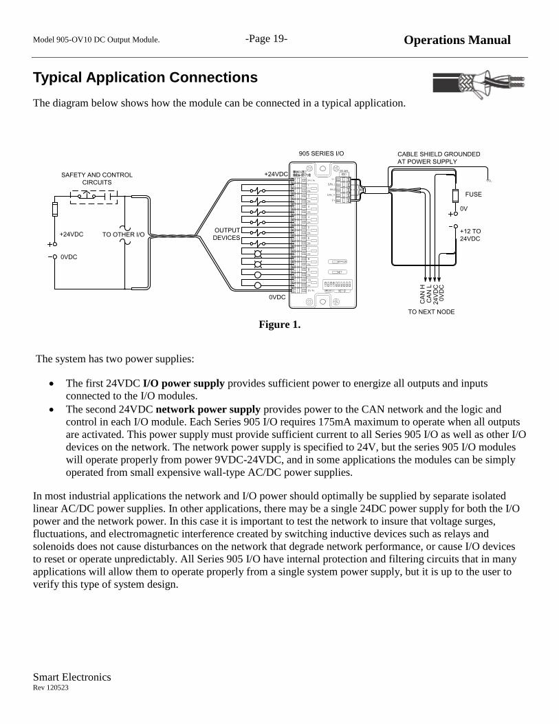
Typical Application Connections
The diagram below shows how the module can be connected in a typical application.
CABLE SHIELD GROUNDED
AT POWER SUPPLY
0VDC
+24VDC TO OTHER I/O
SAFETY AND CONTROL
CIRCUITS
321 7654 9 108
OUTPUT
DEVICES
TO NEXT NODE
CA
N H
CA
N L
24
VD
C0
VD
C
0V
+12 TO
24VDC
FUSE
+24VDC
0VDC
905 SERIES I/O
Figure 1.
The system has two power supplies:
The first 24VDC I/O power supply provides sufficient power to energize all outputs and inputs
connected to the I/O modules.
The second 24VDC network power supply provides power to the CAN network and the logic and
control in each I/O module. Each Series 905 I/O requires 175mA maximum to operate when all outputs
are activated. This power supply must provide sufficient current to all Series 905 I/O as well as other I/O
devices on the network. The network power supply is specified to 24V, but the series 905 I/O modules
will operate properly from power 9VDC-24VDC, and in some applications the modules can be simply
operated from small expensive wall-type AC/DC power supplies.
In most industrial applications the network and I/O power should optimally be supplied by separate isolated
linear AC/DC power supplies. In other applications, there may be a single 24DC power supply for both the I/O
power and the network power. In this case it is important to test the network to insure that voltage surges,
fluctuations, and electromagnetic interference created by switching inductive devices such as relays and
solenoids does not cause disturbances on the network that degrade network performance, or cause I/O devices
to reset or operate unpredictably. All Series 905 I/O have internal protection and filtering circuits that in many
applications will allow them to operate properly from a single system power supply, but it is up to the user to
verify this type of system design.
Model 905-OV10 DC Output Module. -Page 20- Operations Manual
Smart Electronics Rev 120523
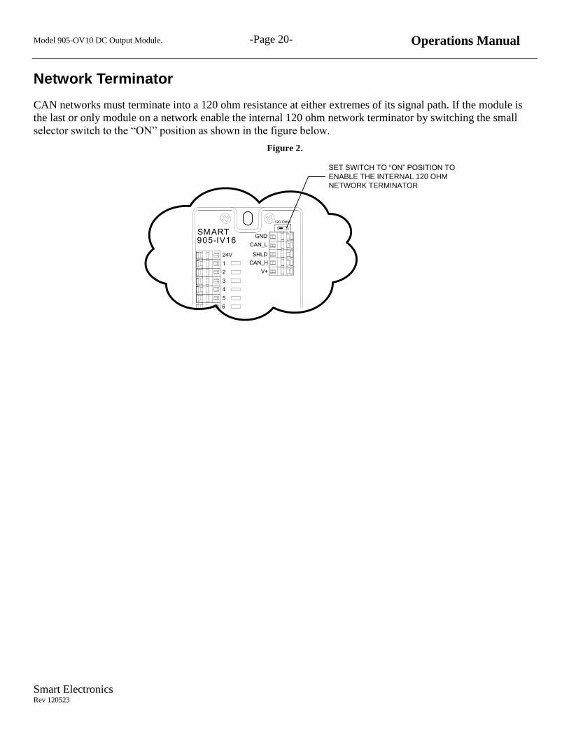
Network Terminator
CAN networks must terminate into a 120 ohm resistance at either extremes of its signal path. If the module is
the last or only module on a network enable the internal 120 ohm network terminator by switching the small
selector switch to the “ON” position as shown in the figure below.
Figure 2.
SMART905-IV16
24V
4
5
3
2
1
GND
CAN_L
SHLD
CAN_H
V+
6
120 OHM
ON
OF
F
SET SWITCH TO “ON” POSITION TO
ENABLE THE INTERNAL 120 OHM
NETWORK TERMINATOR

Model 905-OV10 DC Output Module. -Page 21- Operations Manual
Smart Electronics Rev 120523
LED Indicators
The I/O module has two LED indicators as shown above.
The red “STATUS” LED provides CANopen operations state status and fault condition diagnostic information.
The green “NET” LED indicates the status of the CAN network connection.
Indicator State
Red “Status” Green
“Net” Function
Solid The module is operating properly.
Flashing
steady
The module is operating properly and is in the PRE-OPERATIONAL
CAN network state waiting to be set to OPERATIONAL.
Flashing with
a pause
The module faulted and is proving a fault code for diagnostics. See
the fault code flashing list in the following section.
Alternating Alternating I/O module is in the “Stopped” CANopen state.
Solid CAN network communicating properly in a loaded network.
Flashing The I/O module is waiting in the pre-operational state.
Flickering
The LED flashes on and off for 1/3 second each time the module
successfully receives a CANopen message. In a lightly loaded
network this LED will be seen to be flickering which indicates a
properly functioning network. The length of time that the status light
remains on after receiving or sending a CAN message can be set in
the object dictionary using object 2004.
Diagnostic Status Flash Codes
The RED status LED will flash on and off to signal an internal fault condition. To determine the error code,
count the number of times the LED flashes on and off until there is a longer pause on the flashing. This
indicates the code as below.
Flash Count Function
2 Internal memory error
3 Unit was reset by an internal fault
4 Unexpected message. Wrong message type received.
6 CAN bus error
This is typically caused by a hardware error on the CAN bus, or a CAN wiring fault. If a

Model 905-OV10 DC Output Module. -Page 22- Operations Manual
Smart Electronics Rev 120523
terminating resistor for example is missing the unit will flash this code because of a buss
fault condition.
The CAN bus error may indicate one of the following conditions:
Stuff Error
Form Error
ACK Error
CRC Error
Output Status Indicators
The module has 10 output indicators. These LED lights are wired in series with the output drivers and will light
whenever the output terminal is being activated. The output indicator is powered by the module power not the
output power, and will light even if no output is connected to the terminal.
Model 905-OV10 DC Output Module. -Page 23- Operations Manual
Smart Electronics Rev 120523
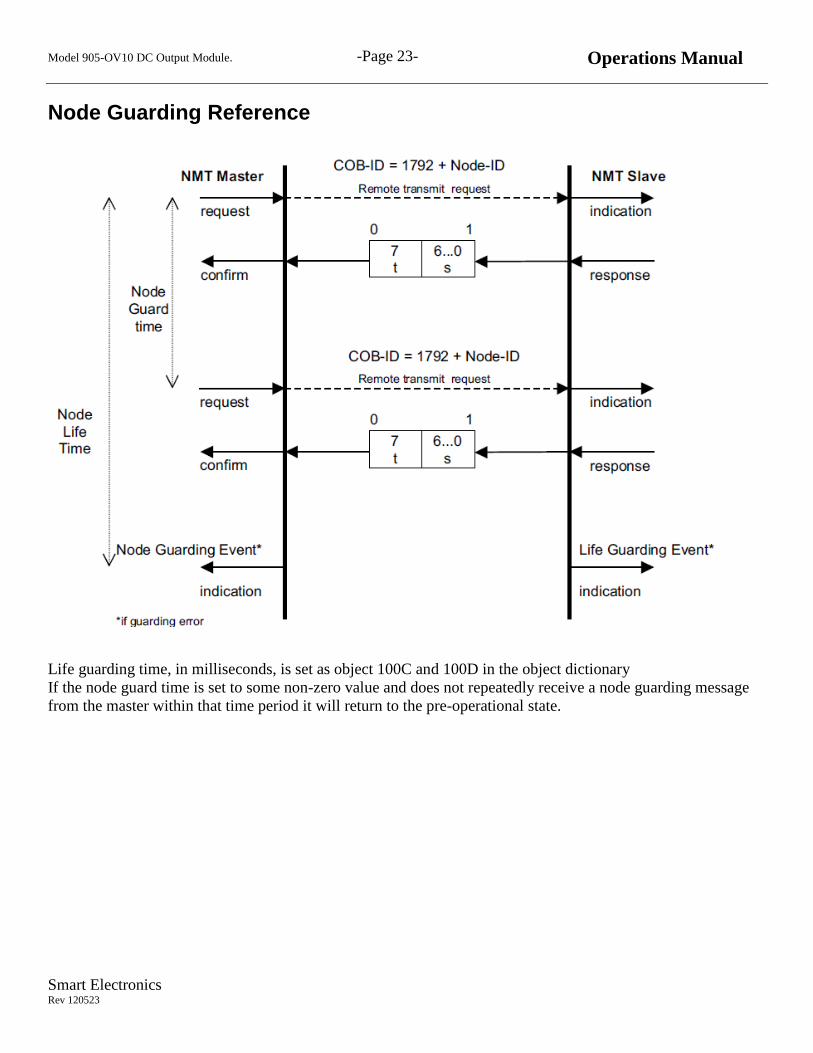
Node Guarding Reference
Life guarding time, in milliseconds, is set as object 100C and 100D in the object dictionary
If the node guard time is set to some non-zero value and does not repeatedly receive a node guarding message
from the master within that time period it will return to the pre-operational state.

Model 905-OV10 DC Output Module. -Page 24- Operations Manual
Smart Electronics Rev 120523
Life Guarding Reference
The heartbeat consumer times are set in object dictionary value 1016. If the module does not receive a heartbeat
message from any of the (up to 10) nodes setup in 1016, it will return to the pre-operational state.
Model 905-OV10 DC Output Module. -Page 25- Operations Manual
Smart Electronics Rev 120523
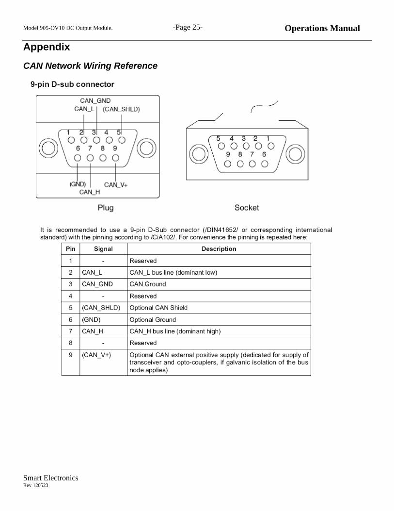
Appendix
CAN Network Wiring Reference

Model 905-OV10 DC Output Module. -Page 26- Operations Manual
Smart Electronics Rev 120523
Table A1. DIP Switch Setting for Node ID 1-63
Node 4 5 6 7 8 9 10 4 5 6 7 8 9 10
TEST* OFF OFF OFF OFF OFF OFF OFF 32 OFF OFF OFF OFF OFF ON OFF
1 ON OFF OFF OFF OFF OFF OFF 33 ON OFF OFF OFF OFF ON OFF
2 OFF ON OFF OFF OFF OFF OFF 34 OFF ON OFF OFF OFF ON OFF
3 ON ON OFF OFF OFF OFF OFF 35 ON ON OFF OFF OFF ON OFF
4 OFF OFF ON OFF OFF OFF OFF 36 OFF OFF ON OFF OFF ON OFF
5 ON OFF ON OFF OFF OFF OFF 37 ON OFF ON OFF OFF ON OFF
6 OFF ON ON OFF OFF OFF OFF 38 OFF ON ON OFF OFF ON OFF
7 ON ON ON OFF OFF OFF OFF 39 ON ON ON OFF OFF ON OFF
8 OFF OFF OFF ON OFF OFF OFF 40 OFF OFF OFF ON OFF ON OFF
9 ON OFF OFF ON OFF OFF OFF 41 ON OFF OFF ON OFF ON OFF
10 OFF ON OFF ON OFF OFF OFF 42 OFF ON OFF ON OFF ON OFF
11 ON ON OFF ON OFF OFF OFF 43 ON ON OFF ON OFF ON OFF
12 OFF OFF ON ON OFF OFF OFF 44 OFF OFF ON ON OFF ON OFF
13 ON OFF ON ON OFF OFF OFF 45 ON OFF ON ON OFF ON OFF
14 OFF ON ON ON OFF OFF OFF 46 OFF ON ON ON OFF ON OFF
15 ON ON ON ON OFF OFF OFF 47 ON ON ON ON OFF ON OFF
16 OFF OFF OFF OFF ON OFF OFF 48 OFF OFF OFF OFF ON ON OFF
17 ON OFF OFF OFF ON OFF OFF 49 ON OFF OFF OFF ON ON OFF
18 OFF ON OFF OFF ON OFF OFF 50 OFF ON OFF OFF ON ON OFF
19 ON ON OFF OFF ON OFF OFF 51 ON ON OFF OFF ON ON OFF
20 OFF OFF ON OFF ON OFF OFF 52 OFF OFF ON OFF ON ON OFF
21 ON OFF ON OFF ON OFF OFF 53 ON OFF ON OFF ON ON OFF
22 OFF ON ON OFF ON OFF OFF 54 OFF ON ON OFF ON ON OFF
23 ON ON ON OFF ON OFF OFF 55 ON ON ON OFF ON ON OFF
24 OFF OFF OFF ON ON OFF OFF 56 OFF OFF OFF ON ON ON OFF
25 ON OFF OFF ON ON OFF OFF 57 ON OFF OFF ON ON ON OFF
26 OFF ON OFF ON ON OFF OFF 58 OFF ON OFF ON ON ON OFF
27 ON ON OFF ON ON OFF OFF 59 ON ON OFF ON ON ON OFF
28 OFF OFF ON ON ON OFF OFF 60 OFF OFF ON ON ON ON OFF
28 ON OFF ON ON ON OFF OFF 61 ON OFF ON ON ON ON OFF
30 OFF ON ON ON ON OFF OFF 62 OFF ON ON ON ON ON OFF
31 ON ON ON ON ON OFF OFF 63 ON ON ON ON ON ON

Model 905-OV10 DC Output Module. -Page 27- Operations Manual
Smart Electronics Rev 120523
Table A1. DIP Switch Setting for Node Id 64-127
Node 4 5 6 7 8 9 10 4 5 6 7 8 9 10
64 OFF OFF OFF OFF OFF OFF ON 96 OFF OFF OFF OFF OFF ON ON
65 ON OFF OFF OFF OFF OFF ON 97 ON OFF OFF OFF OFF ON ON
66 OFF ON OFF OFF OFF OFF ON 98 OFF ON OFF OFF OFF ON ON
67 ON ON OFF OFF OFF OFF ON 99 ON ON OFF OFF OFF ON ON
68 OFF OFF ON OFF OFF OFF ON 100 OFF OFF ON OFF OFF ON ON
69 ON OFF ON OFF OFF OFF ON 101 ON OFF ON OFF OFF ON ON
70 OFF ON ON OFF OFF OFF ON 102 OFF ON ON OFF OFF ON ON
71 ON ON ON OFF OFF OFF ON 103 ON ON ON OFF OFF ON ON
72 OFF OFF OFF ON OFF OFF ON 104 OFF OFF OFF ON OFF ON ON
73 ON OFF OFF ON OFF OFF ON 105 ON OFF OFF ON OFF ON ON
74 OFF ON OFF ON OFF OFF ON 106 OFF ON OFF ON OFF ON ON
75 ON ON OFF ON OFF OFF ON 107 ON ON OFF ON OFF ON ON
76 OFF OFF ON ON OFF OFF ON 108 OFF OFF ON ON OFF ON ON
77 ON OFF ON ON OFF OFF ON 109 ON OFF ON ON OFF ON ON
78 OFF ON ON ON OFF OFF ON 110 OFF ON ON ON OFF ON ON
79 ON ON ON ON OFF OFF ON 110 ON ON ON ON OFF ON ON
80 OFF OFF OFF OFF ON OFF ON 112 OFF OFF OFF OFF ON ON ON
81 ON OFF OFF OFF ON OFF ON 113 ON OFF OFF OFF ON ON ON
82 OFF ON OFF OFF ON OFF ON 114 OFF ON OFF OFF ON ON ON
83 ON ON OFF OFF ON OFF ON 115 ON ON OFF OFF ON ON ON
84 OFF OFF ON OFF ON OFF ON 116 OFF OFF ON OFF ON ON ON
85 ON OFF ON OFF ON OFF ON 117 ON OFF ON OFF ON ON ON
86 OFF ON ON OFF ON OFF ON 118 OFF ON ON OFF ON ON ON
87 ON ON ON OFF ON OFF ON 119 ON ON ON OFF ON ON ON
88 OFF OFF OFF ON ON OFF ON 120 OFF OFF OFF ON ON ON ON
89 ON OFF OFF ON ON OFF ON 121 ON OFF OFF ON ON ON ON
90 OFF ON OFF ON ON OFF ON 122 OFF ON OFF ON ON ON ON
91 ON ON OFF ON ON OFF ON 123 ON ON OFF ON ON ON ON
92 OFF OFF ON ON ON OFF ON 124 OFF OFF ON ON ON ON ON
93 ON OFF ON ON ON OFF ON 125 ON OFF ON ON ON ON ON
94 OFF ON ON ON ON OFF ON 126 OFF ON ON ON ON ON ON
95 ON ON ON ON ON OFF ON 127 ON ON ON ON ON ON ON

Model 905-OV10 DC Output Module. -Page 28- Operations Manual
Smart Electronics Rev 120523
Mounting Dimensions
5 [1
27
mm
]
5.5
[1
39
.7 m
m]
2.5 [63.5 mm]
21 5 643 1087 9
0.3 x 0.2 [7.62 x 5.08 mm]

Model 905-OV10 DC Output Module. -Page 29- Operations Manual
Smart Electronics Rev 120523
Contact Information
Smart Electronics Corp.
17-760 Pacific Road
Oakville, Ontario
Canada L6L6M5
Tel: 905-847-2598
www.smartelectronics.ca


![J1939 CANopen gateway - umu.se · J1939-CANopen gateway _____ 24 3 CANopen CANopen [3] is a higher layer protocol for CAN based networks. It is an offspring from CAL (see Section](https://img.pdfslide.net/doc/110x75/5e7174efe1907e55be07658a/j1939-canopen-gateway-umu-j1939-canopen-gateway-24-3-canopen-canopen-3.jpg)