Embed Size (px)
Citation preview
Series CircuitsSeries Circuits
Topics Covered in Chapter 4
4-1: Why I Is the Same in All Parts of a Series Circuit
4-2: Total R Equals the Sum of All Series Resistances
4-3: Series IR Voltage Drops
4-4: Kirchhoff’s Voltage Law (KVL)
4-5: Polarity of IR Voltage Drops
ChapterChapter
44
© 2007 The McGraw-Hill Companies, Inc. All rights reserved.
Topics Covered in Chapter 4Topics Covered in Chapter 4
4-6: Total Power in a Series Circuit
4-7: Series-Aiding and Series-Opposing Voltages
4-8: Analyzing Series Circuits with Random Unknowns
4-9: Ground Connections in Electrical and Electronic Systems
4-10: Troubleshooting: Opens and Shorts in Series Circuits
McGraw-Hill © 2007 The McGraw-Hill Companies, Inc. All rights reserved.
44--1: Why 1: Why I I Is the Same in All Parts of Is the Same in All Parts of
a Series Circuita Series Circuit
Characteristics of a Series Circuit
The current is the same everywhere in a series circuit.
The total resistance is equal to the sum of the individual
resistance values.
The total voltage is equal to the sum of the IR voltage
drops across the individual resistances.
The total power is equal to the sum of the power
dissipated by each resistance.
44--1: Why 1: Why I I Is the Same in All Parts of Is the Same in All Parts of
a Series Circuita Series Circuit
Current is the movement of electric charge between two
points, produced by the applied voltage.
The free electrons moving away from one point are
continuously replaced by free electrons flowing from an
adjacent point in the series circuit.
All electrons have the same speed as those leaving the
voltage source.
Therefore, I is the same in all parts of a series circuit.
44--1: Why 1: Why I I Is the Same in All Parts of Is the Same in All Parts of
a Series Circuita Series Circuit
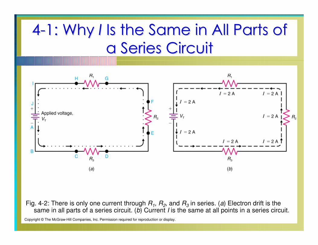
Fig. 4-2: There is only one current through R1, R2, and R3 in series. (a) Electron drift is the same in all parts of a series circuit. (b) Current I is the same at all points in a series circuit.
Copyright © The McGraw-Hill Companies, Inc. Permission required for reproduction or display.
44--1: Why 1: Why I I Is the Same in All Parts of Is the Same in All Parts of
a Series Circuita Series Circuit
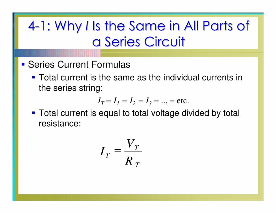
Series Current Formulas
Total current is the same as the individual currents in
the series string:
IT
= I1
= I2
= I3
= ... = etc.
Total current is equal to total voltage divided by total
resistance:
IV
RT
T
T
=

44--2: Total 2: Total RR Equals the Sum of All Equals the Sum of All
Series ResistancesSeries Resistances
When a series circuit is connected across a voltage
source, the free electrons must drift through all the
series resistances.
There is only one path for free electrons to follow.
If there are two or more resistances in the same current
path, the total resistance across the voltage source is
the sum of all the resistances.

44--2: Total 2: Total RR Equals the Sum of All Equals the Sum of All
Series ResistancesSeries Resistances
Fig. 4-4: Series resistances are added for the total RT. (a) R1 alone is 3 Ω. (b) R1 and R2 in series together total 5 Ω. (c) The RT of 5 Ω is the same as one resistance of 5 Ω between points A and B.
Copyright © The McGraw-Hill Companies, Inc. Permission required for reproduction or display.

44--2: Total 2: Total RR Equals the Sum of All Equals the Sum of All
Series ResistancesSeries Resistances
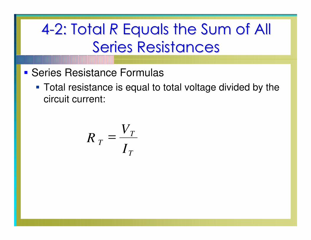
Series Resistance Formulas
The total resistance is the sum of the individual
resistances.
RT = R1 + R2 + R3 + R4 + R5
R1
R2
R3
R4
R5
44--2: Total 2: Total RR Equals the Sum of All Equals the Sum of All
Series ResistancesSeries Resistances
Series Resistance Formulas
Total resistance is equal to total voltage divided by the
circuit current:
RV
IT
T
T
=
44--2: Total 2: Total RR Equals the Sum of All Equals the Sum of All
Series ResistancesSeries Resistances
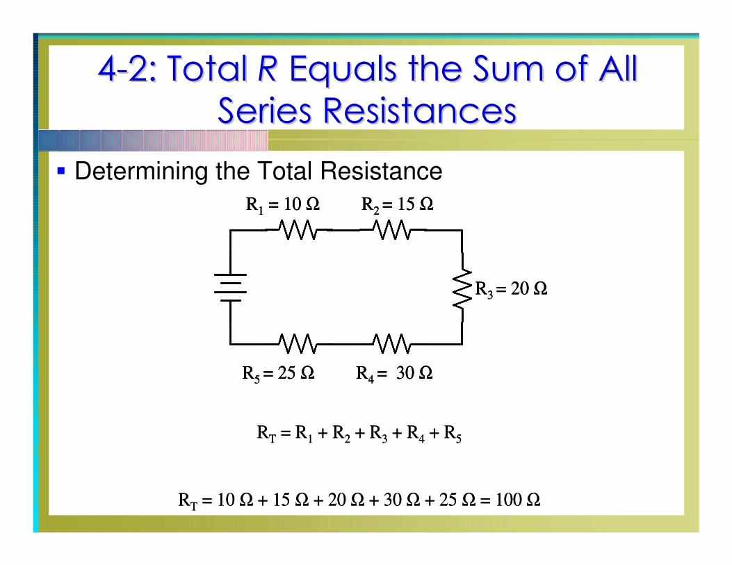
Determining the Total Resistance
RT = R1 + R2 + R3 + R4 + R5
R1 = 10 Ω R2 = 15 Ω
R3 = 20 Ω
R4 = 30 ΩR5 = 25 Ω
RT = 10 Ω + 15 Ω + 20 Ω + 30 Ω + 25 Ω = 100 Ω
RT = R1 + R2 + R3 + R4 + R5
R1 = 10 Ω R2 = 15 Ω
R3 = 20 Ω
R4 = 30 ΩR5 = 25 Ω
R1 = 10 Ω R2 = 15 Ω
R3 = 20 Ω
R4 = 30 ΩR5 = 25 Ω
RT = 10 Ω + 15 Ω + 20 Ω + 30 Ω + 25 Ω = 100 Ω

44--3: Series3: Series IRIR Voltage DropsVoltage Drops
By Ohm’s Law, the voltage across a resistance equals
I × R.
In a series circuit, the IR voltage across each resistance
is called an IR drop or voltage drop, because it
reduces the potential difference available for the
remaining resistances in the circuit.

44--3: Series3: Series IRIR Voltage DropsVoltage Drops
Fig. 4-5: An example of IR voltage drops V1 and V2 in a series circuit.
Copyright © The McGraw-Hill Companies, Inc. Permission required for reproduction or display.
44--4: Kirchhoff4: Kirchhoff’’s Voltage Law (KVL)s Voltage Law (KVL)
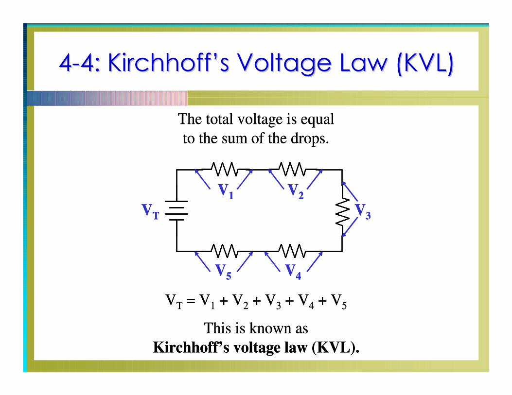
The total voltage is equal
to the sum of the drops.
VT = V1 + V2 + V3 + V4 + V5
V1 V2
V3
V4V5
VT
This is known as
Kirchhoff’s voltage law (KVL).
The total voltage is equal
to the sum of the drops.
VT = V1 + V2 + V3 + V4 + V5
V1 V2
V3
V4V5
VT
V1 V2
V3
V4V5
VT
This is known as
Kirchhoff’s voltage law (KVL).
44--4: Kirchhoff4: Kirchhoff’’s Voltage Law (KVL)s Voltage Law (KVL)
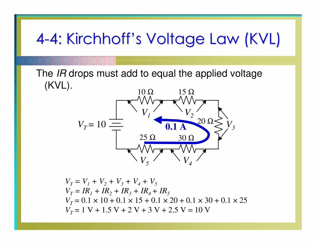
The IR drops must add to equal the applied voltage
(KVL).
VT
= V1
+ V2
+ V3
+ V4
+ V5
VT
= IR1
+ IR2
+ IR3
+ IR4 + IR
5
VT
= 0.1 × 10 + 0.1 × 15 + 0.1 × 20 + 0.1 × 30 + 0.1 × 25
VT
= 1 V + 1.5 V + 2 V + 3 V + 2.5 V = 10 V
V1
V2
V3
V4
V5
VT
= 10
10 Ω
20 Ω
15 Ω
25 Ω 30 Ω
0.1 A
44--5: Polarity of 5: Polarity of IR IR Voltage DropsVoltage Drops
When current flows through a resistor, a voltage equal
to IR is dropped across the resistor. The polarity of this
IR voltage drop is:
Negative at the end where the electrons enter the
resistor.
Positive at the end where the electrons leave the
resistor.
44--5: Polarity of 5: Polarity of IR IR Voltage DropsVoltage Drops
The rule is reversed when considering conventional
current: positive charges move into the positive side of
the IR voltage.
The polarity of the IR drop is the same, regardless of
whether we consider electron flow or conventional
current.
44--5: Polarity of 5: Polarity of IR IR Voltage DropsVoltage Drops
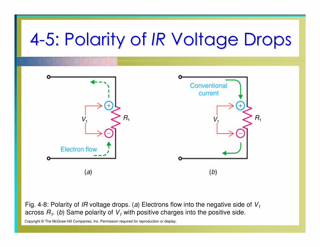
Fig. 4-8: Polarity of IR voltage drops. (a) Electrons flow into the negative side of V1
across R1. (b) Same polarity of V1 with positive charges into the positive side.
Copyright © The McGraw-Hill Companies, Inc. Permission required for reproduction or display.
44--6: Total Power in a Series Circuit6: Total Power in a Series Circuit
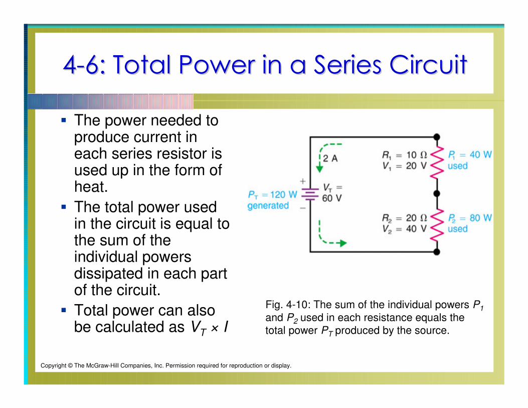
The power needed to produce current in each series resistor is used up in the form of heat.
The total power used in the circuit is equal to the sum of the individual powers dissipated in each part of the circuit.
Total power can also be calculated as VT × I
Fig. 4-10: The sum of the individual powers P1
and P2 used in each resistance equals the
total power PT produced by the source.
Copyright © The McGraw-Hill Companies, Inc. Permission required for reproduction or display.
44--6: Total Power in a Series Circuit6: Total Power in a Series Circuit
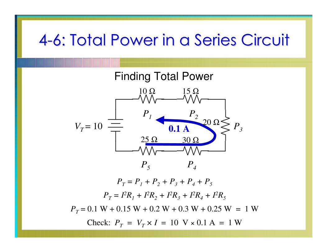
Finding Total Power
PT
= P1
+ P2
+ P3
+ P4
+ P5
PT
= I2R1
+ I2R2
+ I2R3
+ I2R4
+ I2R5
PT
= 0.1 W + 0.15 W + 0.2 W + 0.3 W + 0.25 W = 1 W
Check: PT
= VT
× I = 10 V × 0.1 A = 1 W
P1
P2
P3
P4
P5
VT
= 10
10 Ω
20 Ω
15 Ω
25 Ω 30 Ω
0.1 A
44--7: Series7: Series--Aiding and Aiding and
SeriesSeries--Opposing VoltagesOpposing Voltages
Series-aiding voltages are connected with polarities that
allow current in the same direction:
The positive terminal of one is connected to the
negative terminal of the next.
They can be added for the total voltage.

44--7: Series7: Series--Aiding and Aiding and
SeriesSeries--Opposing VoltagesOpposing Voltages
Series-opposing voltages are the opposite: They are connected to produce opposing directions of current flow.
The positive terminal of one is connected to the positive terminal of another.
To obtain the total voltage, subtract the smaller voltage from the larger.
Two equal series-opposing voltage sources have a net voltage of zero.
44--7: Series7: Series--Aiding and Aiding and
SeriesSeries--Opposing VoltagesOpposing Voltages
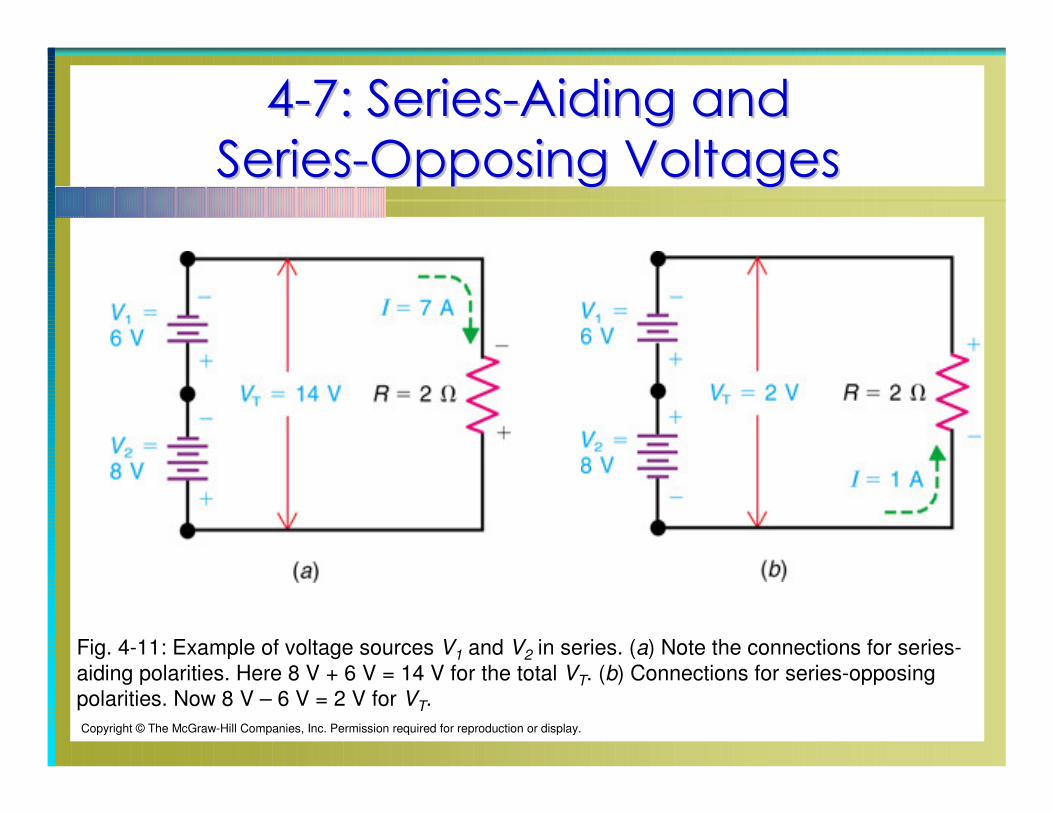
Fig. 4-11: Example of voltage sources V1 and V2 in series. (a) Note the connections for series-
aiding polarities. Here 8 V + 6 V = 14 V for the total VT. (b) Connections for series-opposing
polarities. Now 8 V – 6 V = 2 V for VT.
Copyright © The McGraw-Hill Companies, Inc. Permission required for reproduction or display.
44--8: Analyzing Series Circuits with 8: Analyzing Series Circuits with
Random UnknownsRandom Unknowns
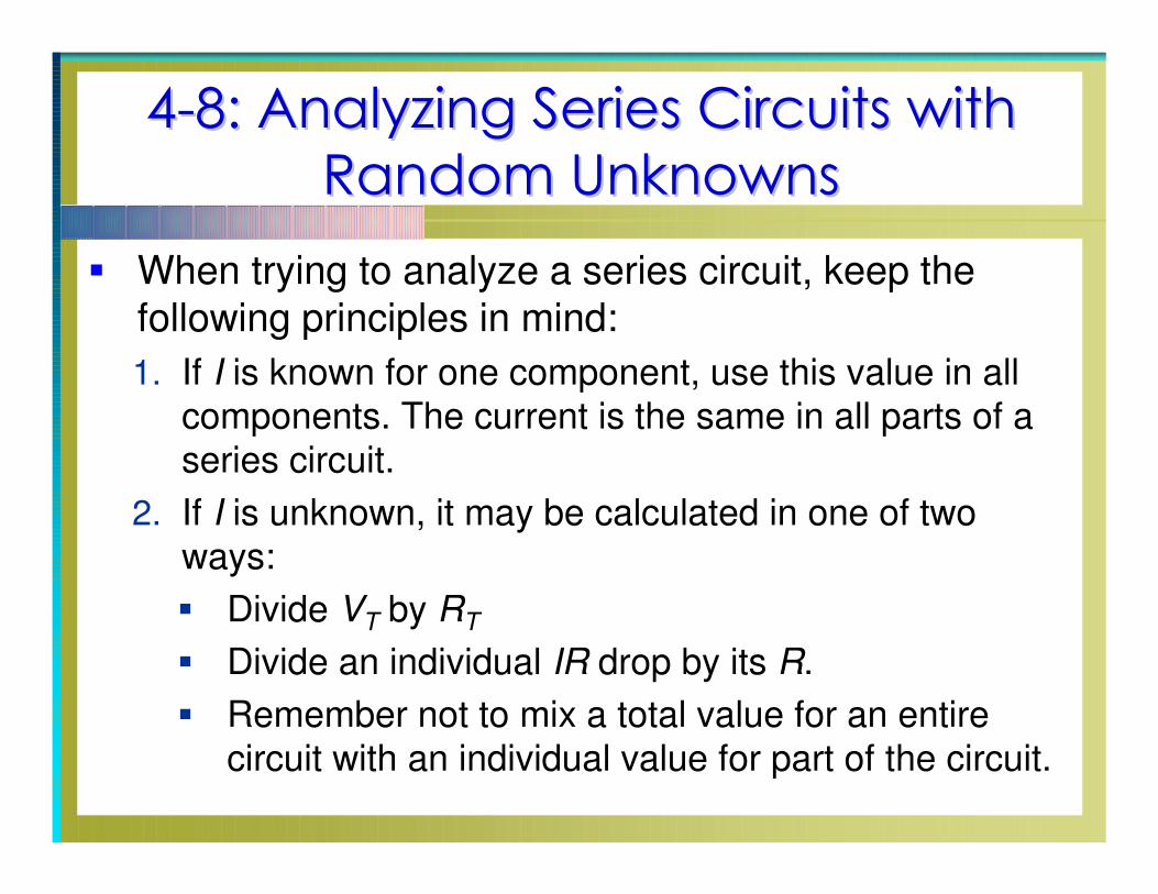
When trying to analyze a series circuit, keep the following principles in mind:
1. If I is known for one component, use this value in all
components. The current is the same in all parts of a
series circuit.
2. If I is unknown, it may be calculated in one of two
ways:
Divide VT by RT
Divide an individual IR drop by its R.
Remember not to mix a total value for an entire
circuit with an individual value for part of the circuit.
44--8: Analyzing Series Circuits with 8: Analyzing Series Circuits with
Random UnknownsRandom Unknowns
3. If all individual voltage drops are known, add them to
determine the applied VT.
A known voltage drop may be subtracted from VT to
find a remaining voltage drop.
44--9: Ground Connections in 9: Ground Connections in
Electrical and Electronic SystemsElectrical and Electronic Systems
In most electrical and electronic systems, one side of
the voltage source is connected to ground.
The reason for doing this is to reduce the possibility of
electric shock.

44--9: Ground Connections in 9: Ground Connections in
Electrical and Electronic SystemsElectrical and Electronic Systems
Figure 4-16 shows several schematic ground symbols:
Ground is assumed to have a potential of 0 V
regardless of the schematic symbol shown.
These symbols are sometimes used inconsistently with
their definitions. However, these symbols always
represent a common return path for current in a given
circuit.Copyright © The McGraw-Hill Companies, Inc. Permission required for reproduction or display.

44--9: Ground Connections in 9: Ground Connections in
Electrical and Electronic SystemsElectrical and Electronic Systems
Voltages Measured with Respect to Ground
When a circuit has a ground as a common return,
measure the voltages with respect to this ground.
44--9: Ground Connections in 9: Ground Connections in
Electrical and Electronic SystemsElectrical and Electronic Systems
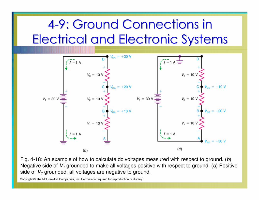
Fig. 4-18: An example of how to calculate dc voltages measured with respect to ground. (b)
Negative side of VT grounded to make all voltages positive with respect to ground. (d) Positive
side of VT grounded, all voltages are negative to ground.
Copyright © The McGraw-Hill Companies, Inc. Permission required for reproduction or display.
44--10: Troubleshooting: Opens and 10: Troubleshooting: Opens and
Shorts in Series CircuitsShorts in Series Circuits
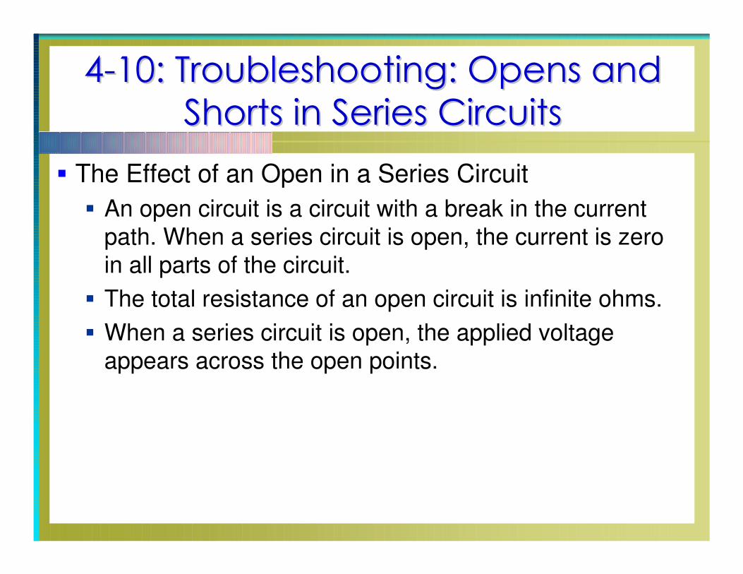
The Effect of an Open in a Series Circuit
An open circuit is a circuit with a break in the current
path. When a series circuit is open, the current is zero
in all parts of the circuit.
The total resistance of an open circuit is infinite ohms.
When a series circuit is open, the applied voltage
appears across the open points.
44--10: Troubleshooting: Opens and 10: Troubleshooting: Opens and
Shorts in Series CircuitsShorts in Series Circuits
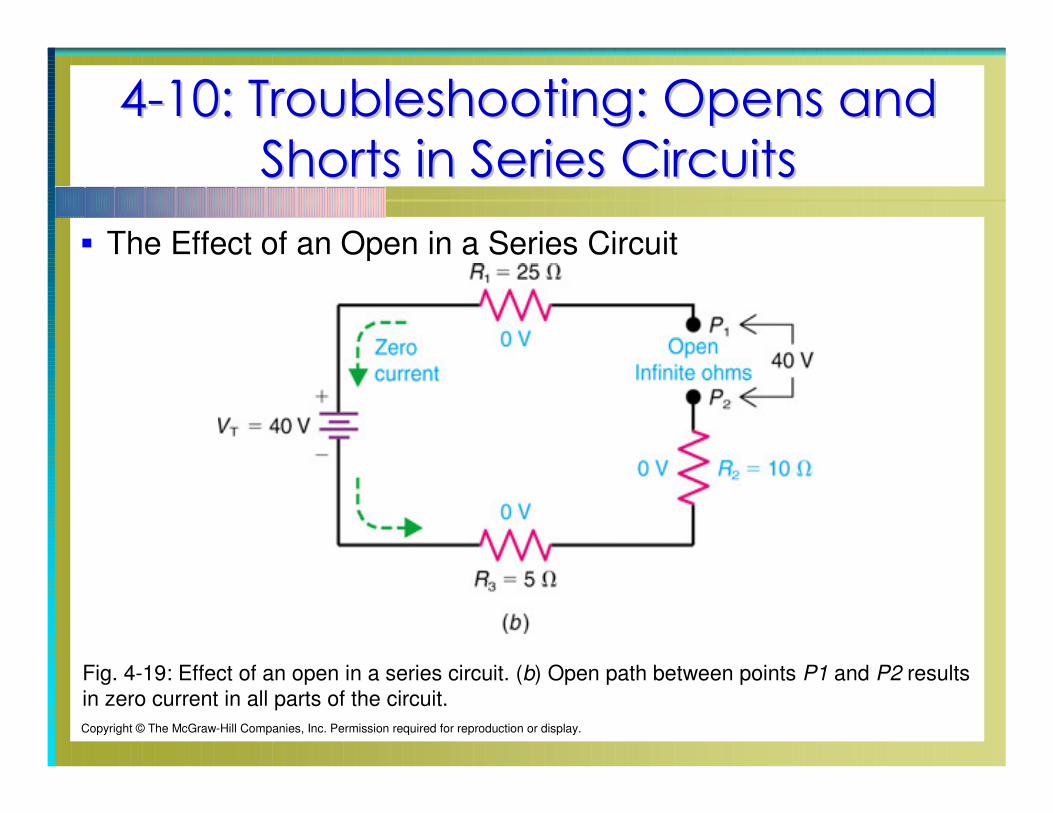
The Effect of an Open in a Series Circuit
Fig. 4-19: Effect of an open in a series circuit. (b) Open path between points P1 and P2 results
in zero current in all parts of the circuit.
Copyright © The McGraw-Hill Companies, Inc. Permission required for reproduction or display.
44--10: Troubleshooting: Opens and 10: Troubleshooting: Opens and
Shorts in Series CircuitsShorts in Series Circuits
Applied voltage VT is still present, even with zero
current.
The voltage source still has its same potential difference
across its positive and negative terminals.
Example: The 120-V potential difference is always
available from the terminals of a wall outlet. If an appliance is connected, current will flow.
If you touch the metal terminals when nothing else is connected, you will receive a shock.
44--10: Troubleshooting: Opens and 10: Troubleshooting: Opens and
Shorts in Series CircuitsShorts in Series Circuits
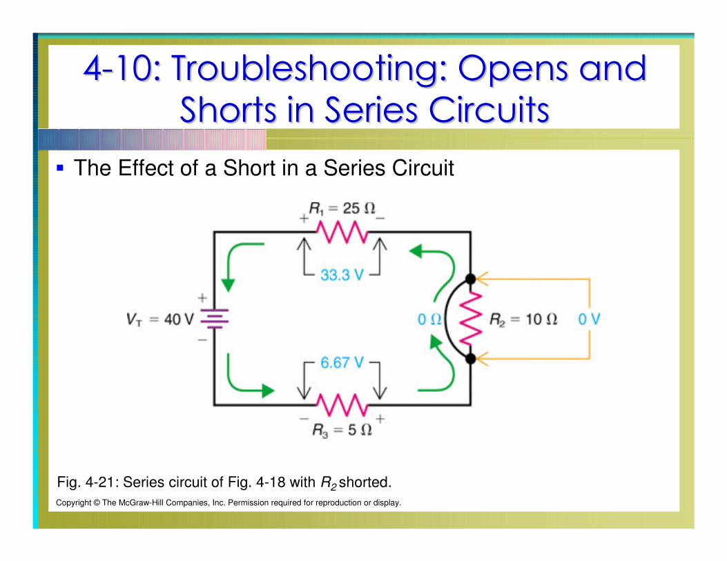
The Effect of a Short in a Series Circuit
When part of a series circuit is shorted, the current flow
increases.
When part of a series circuit is shorted, the voltage
drops across the non-shorted elements increase.
The voltage drop across the shorted component drops
to 0 V.
44--10: Troubleshooting: Opens and 10: Troubleshooting: Opens and
Shorts in Series CircuitsShorts in Series Circuits
The Effect of a Short in a Series Circuit
Fig. 4-21: Series circuit of Fig. 4-18 with R2 shorted.
Copyright © The McGraw-Hill Companies, Inc. Permission required for reproduction or display.

44--10: Troubleshooting: Opens and 10: Troubleshooting: Opens and
Shorts in Series CircuitsShorts in Series Circuits
When troubleshooting a series circuit containing three
or more resistors, remember:
The component whose voltage changes in the
opposite direction of the other components is the
defective component.