Embed Size (px)
Citation preview

Manual Hardware and Software
Series EE240
WirElESS SENSOr FOrHUMiDiTY
TEMPErATUrECO2
BA_EE240_e // v5.0 // technical data are subject to change // 350118
2
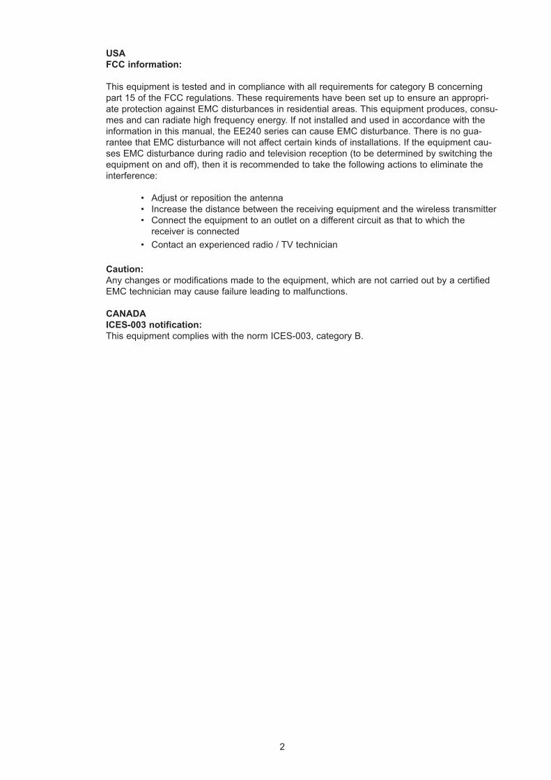
USAFCC information:
This equipment is tested and in compliance with all requirements for category B concerning part 15 of the FCC regulations. These requirements have been set up to ensure an appropri-ate protection against EMC disturbances in residential areas. This equipment produces, consu-mes and can radiate high frequency energy. If not installed and used in accordance with the information in this manual, the EE240 series can cause EMC disturbance. There is no gua-rantee that EMC disturbance will not affect certain kinds of installations. If the equipment cau-ses EMC disturbance during radio and television reception (to be determined by switching the equipment on and off), then it is recommended to take the following actions to eliminate the interference:
• Adjust or reposition the antenna• Increase the distance between the receiving equipment and the wireless transmitter• Connect the equipment to an outlet on a different circuit as that to which the
receiver is connected• Contact an experienced radio / TV technician
Caution:Any changes or modifications made to the equipment, which are not carried out by a certified EMC technician may cause failure leading to malfunctions.
CANADAICES-003 notification:This equipment complies with the norm ICES-003, category B.
3
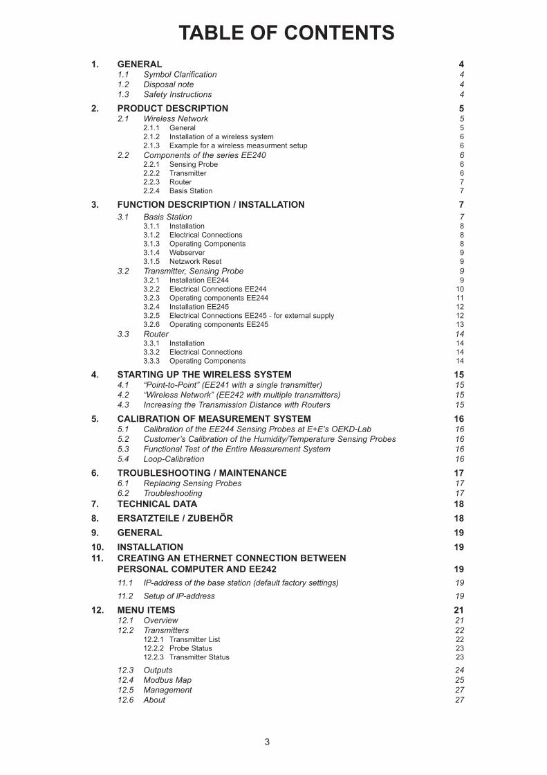
TABLE OF CONTENTS1. GENERAL 4
1.1 Symbol Clarification 41.2 Disposal note 41.3 Safety Instructions 4
2. PRODUCT DESCRIPTION 52.1 Wireless Network 5
2.1.1 General 52.1.2 Installation of a wireless system 62.1.3 Example for a wireless measurment setup 6
2.2 Components of the series EE240 62.2.1 Sensing Probe 62.2.2 Transmitter 62.2.3 Router 72.2.4 Basis Station 7
3. FUNCTION DESCRIPTION / INSTALLATION 73.1 Basis Station 7
3.1.1 Installation 83.1.2 Electrical Connections 83.1.3 Operating Components 83.1.4 Webserver 93.1.5 Netzwork Reset 9
3.2 Transmitter, Sensing Probe 93.2.1 Installation EE244 93.2.2 Electrical Connections EE244 103.2.3 Operating components EE244 113.2.4 Installation EE245 123.2.5 Electrical Connections EE245 - for external supply 123.2.6 Operating components EE245 13
3.3 Router 143.3.1 Installation 143.3.2 Electrical Connections 143.3.3 Operating Components 14
4. STARTING UP THE WIRELESS SYSTEM 154.1 “Point-to-Point” (EE241 with a single transmitter) 154.2 “Wireless Network” (EE242 with multiple transmitters) 154.3 Increasing the Transmission Distance with Routers 15
5. CALIBRATION OF MEASUREMENT SYSTEM 165.1 Calibration of the EE244 Sensing Probes at E+E’s OEKD-Lab 165.2 Customer’s Calibration of the Humidity/Temperature Sensing Probes 165.3 Functional Test of the Entire Measurement System 165.4 Loop-Calibration 16
6. TROUBLESHOOTING / MAINTENANCE 176.1 Replacing Sensing Probes 176.2 Troubleshooting 17
7. TECHNICAL DATA 188. ERSATZTEILE / ZUBEHÖR 189. GENERAL 1910. INSTALLATION 1911. CREATING AN ETHERNET CONNECTION BETWEEN PERSONAL COMPUTER AND EE242 19
11.1 IP-address of the base station (default factory settings) 1911.2 Setup of IP-address 19
12. MENU ITEMS 2112.1 Overview 2112.2 Transmitters 22
12.2.1 Transmitter List 2212.2.2 Probe Status 2312.2.3 Transmitter Status 23
12.3 Outputs 2412.4 Modbus Map 2512.5 Management 2712.6 About 27
4
1. GENERAL
This manual is a part of the scope of supply and serves to ensure optimal operation and functioning of the equipment. E+E Elektronik® Ges.m.b.H. cannot be hold responsible for the incorrect handling, installation, and maintenance of the equipment described in this publication. Therefore, it is necessary that this manual is read and understood by those responsible for the handling, installation, and maintenance of the equipment. This manual may not be used for competitive purposes or passed on to third parties without the written consent of E+E Elektronik® Ges.m.b.H. It is permitted to make copies for personal use.
This publication can contain technical inaccuracies or typographic errors. The content of this manual is updated on a regular basis and not subject to change. The manufacturer reserves the right to modify or change the equipment described in this manual without prior notice.
©Copyright E+E Elektronik® Ges.m.b.H. All rights reserved
1.1 Symbol Clarification
This symbol indicates safety instructions.The safety instructions have to be carried out unconditionally. If disregarded loss, injury, or damage may be inflicted to people and property. In any case E+E Elektronik® Ges.m.bH. can-not be hold responsible.
This symbol indicates attention.The note should be observed to achieve an optimal functioning of the equipment.
1.2 Disposal note
The crossed-out wheeled-bin symbol on your product, literature or packaging reminds you that all products must be taken to separate collection in the European Union. do not dispose of these products as unsorted municipal waste.
Return the products to collection to prevent possible harm to the environment or human health and support the sustainable reuse of material resources
1.3 Safety Instructions
General safety instructions
• Excessive mechanical stress and inappropriate handling must be avoided.• Caution: the sensor element can be damaged when unscrewing the filter cap.• The sensor element is an ESD-sensitive device; therefore, handling the sensor
element ESD related precautionary measures have to be taken.• Mounting, electrical installation, putting in operation and maintenance should
only be done by qualified personnel.
Specific safety instructions for “Wireless”
Standards:CE: Electromagnetic Compatibility according EN61326-1 and EN61326-2-3 / Industrial environmentFCC: Part 15 Class BICES: ICES-003 Class B
5
ZulassungenUnited States (FCC Part 15.247) FCC ID: OUR-XBEE2 FCC ID: MCQ-XBEEPRO2Industrie Kanada (IC) IC: 4214A-XBEE2 IC: 1846A-XBEEPRO2Europa (CE) ETSI ETSIAustralien C-Tick C-TickJapan R201WW07215215 R201WW08215142
Transmission module:Contains FCC ID:MCQ-XBEEPRO2Contains Model XBee PRO Radio; IC: 1846A-XBEEPRO2
This equipment complies with Part 15 of the FCC Rules. Operation is subject to the following conditions:
• this device may not cause harmful interference • under direct influence of EMC interference the device must continue to function,
including interference that may cause an undesired operational situation•
FCC ID: MCQ-XBEEPRO2 (part 15 of the FCC regulations)IC: 1846A-XBEEPRO2 (Canada accept FCC’s audit report about the compliance with ICES-003)Europe CE: CEPT ERC 70-03E / R&TTE Directive (no special marking, except CE)
Specific Instructions:The transmission energy of the series EE 240 is limited according to certain standards, alterations of the electronics are therefore, with respect to the transmission license, prohibited.
Norway:In the Svinsdal area is it not allowed to operate a device for radio communication.
USA: The antenna must be mounted more than 20cm (8 inches) away from any human body.
2. PRODUCT DESCRIPTIONThe wireless transmitter series EE240 combines modern sensor technology, easiest system installation and the highest reliability of the data transmission. The several different modules of the series EE240 are within a short time operational. No matter if it is a point-to-point connec-tion or a comprehensive network, the series EE240 offers the ideal solution.
2.1 Wireless Network
2.1.1 General
The series EE240, based on the “ZigBee” protocol, transmits at a frequency of 2.4 GHz with a power of 10 mW. A bi-directional wireless connection prevents loss of data, if disturbances may occur. The maximum transmission distance depends greatly on the local conditions. Obstacles, like walls of reinforced concrete, steel buildings, or structures attenuate the signal and decreases the transmission distance.
6
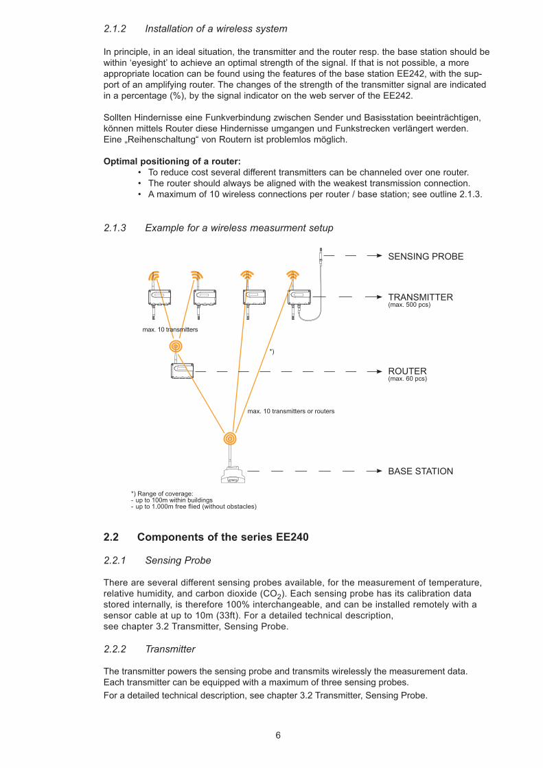
SENSING PROBE
TRANSMITTER(max. 500 pcs)
ROUTER (max. 60 pcs)
BASE STATION
max. 10 transmitters
*) Range of coverage: - up to 100m within buildings-upto1.000mfreeflied(withoutobstacles)
*)
max. 10 transmitters or routers
2.1.2 Installation of a wireless system
In principle, in an ideal situation, the transmitter and the router resp. the base station should be within ‘eyesight’ to achieve an optimal strength of the signal. If that is not possible, a more appropriate location can be found using the features of the base station EE242, with the sup-port of an amplifying router. The changes of the strength of the transmitter signal are indicated in a percentage (%), by the signal indicator on the web server of the EE242.
Sollten Hindernisse eine Funkverbindung zwischen Sender und Basisstation beeinträchtigen, können mittels Router diese Hindernisse umgangen und Funkstrecken verlängert werden.Eine „Reihenschaltung“ von Routern ist problemlos möglich.
Optimal positioning of a router:• To reduce cost several different transmitters can be channeled over one router.• The router should always be aligned with the weakest transmission connection.• A maximum of 10 wireless connections per router / base station; see outline 2.1.3.
2.1.3 Example for a wireless measurment setup
2.2 Components of the series EE240
2.2.1 Sensing Probe
There are several different sensing probes available, for the measurement of temperature, relative humidity, and carbon dioxide (CO2). Each sensing probe has its calibration data stored internally, is therefore 100% interchangeable, and can be installed remotely with a sensor cable at up to 10m (33ft). For a detailed technical description, see chapter 3.2 Transmitter, Sensing Probe.
2.2.2 Transmitter
The transmitter powers the sensing probe and transmits wirelessly the measurement data.Each transmitter can be equipped with a maximum of three sensing probes.For a detailed technical description, see chapter 3.2 Transmitter, Sensing Probe.
7
2.2.3 Router
The router is designed to increase the overall transmission distance and to bypass obstacles. Each router has the ability to receive and transmit a maximum of 10 signals (trans-mitter or another router). It is not possible to connect measuring probes to a routerFor a detailed technical description, see chapter 3.3 Router
2.2.4 Basis Station
The base station processes the data of the sensing probe and output an analogue or digital signal. Each base station has four analogue outputs and a (optional) display. The base station of the series EE240 does not have a data logger.For a detailed technical description, see chapter 3.1 Base Station.
3. FUNCTION DESCRIPTION / INSTALLATION
3.1 Basis Station
Depending on the application two different systems can be set up:
1) “Point–to-Point” (EE241 with a single transmitter)This setup offers a cost friendly solution to transmit wirelessly a few measurement values (e.g. a temperature and a humidity measurement). The EE241 can communicate with only a single transmitter EE244, in between the two any desired number of routers can be installed to increase the transmission distance.The EE241 has for each measured value only one channel available (temperature, humidity, CO2). E.g. it is not possible to transmit two temperature signals simultaneously. There is no personal computer necessary to configure the EE241 – the desired setup is configured by E+E in accordance with the ordering code.
2) “Wireless Network” (EE242 with multiple transmitters)With the EE242 a comprehensive wireless network can be build. The network can consist out of 500 transmitters and 50 routers. Each base station can receive a maximum of 10 signals (router or transmitter) The Ethernet interface, Modbus and Webserver allow for easy configuration of the system.
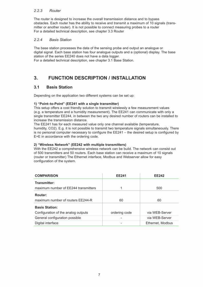
COMPARISON EE241 EE242
Transmitter:maximum number of EE244 transmitters 1 500
Router:maximum number of routers EE244-R 60 60
Basis Station:Configuration of the analog outputs ordering code via WEB-ServerGeneralconfigurationpossible - via WEB-ServerDigital interface - Ethernet, Modbus
8
11 (4
.3")
11
(4.3
")
62 (2.4")108 (4.3") 5 (0.2")
90 (3
.5")
Pluggable antenna which can also be ordered with a remote cable (antenna cable refer to accessories)
Hut
schi
enen
mon
tage
1 2 3 4 5 6 7 8 9 10 11 12 13 14 15 16
V+
GN
D
GN
D
GN
D
GN
D
GN
D
NC
NC
NC
GN
D B-
A+
OU
T1
OU
T2
OU
T3
OU
T424V AC/DC*
+ _V/mA
V/mA
V/mA
V/mA
SELV
RS485 Modbus RTU
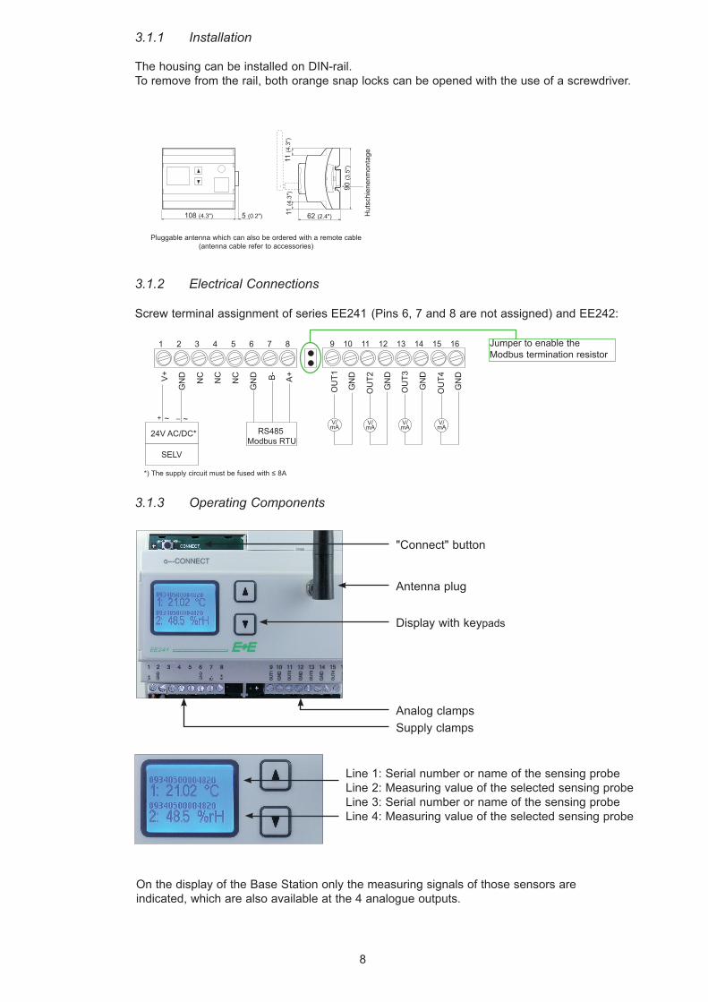
Screw terminal assignment of series EE241 (Pins 6, 7 and 8 are not assigned) and EE242:
3.1.3 Operating Components
Line 1: Serial number or name of the sensing probeLine 2: Measuring value of the selected sensing probeLine 3: Serial number or name of the sensing probeLine 4: Measuring value of the selected sensing probe
"Connect" button
Display with keypads
Antenna plug
Supply clampsAnalog clamps
On the display of the Base Station only the measuring signals of those sensors are indicated, which are also available at the 4 analogue outputs.
*) Thesupplycircuitmustbefusedwith≤8A
3.1.1 Installation
The housing can be installed on DIN-rail. To remove from the rail, both orange snap locks can be opened with the use of a screwdriver.
3.1.2 Electrical Connections
Jumper to enable the Modbus termination resistor
9
32
1841
Ø13 (0,5")
Ø13 (0,5")
25
(1")(1.3
")(1
.3")
18
(0.7
")
(0.7
")
50 (2")
(3.3
")(1
.6")
Ø6 (0.2")
Ø12 (0.4")
32
83
3.1.4 Webserver
The EE242 can be set up with any desired configuration by means of the webserver; as a result one has full control of the entire network. The base station of the series E240 does not have a data logger. For a detailed technical description, see chapter „Configuration Software“.
3.1.5 Netzwork Reset
To reset the system to the default factory settings, the push-button “Connect” should be pressed for 10 seconds.• EE241: the wireless connection with the transmitter will be cancelled.• EE242: all wireless connections (with transmitters and routers) will be cancelled. All settings will reset to the default factory settings: IP address of the base station, password of the web server, etc.
3.2 Transmitter, Sensing Probe
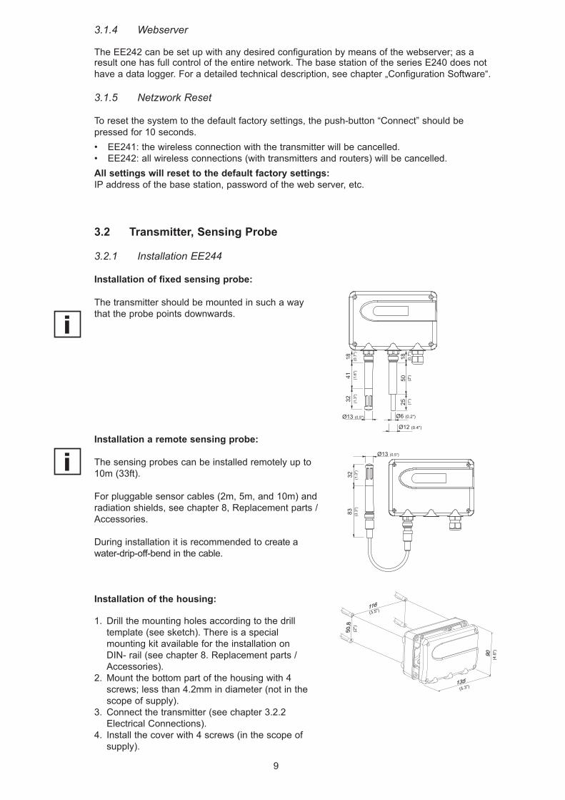
3.2.1 Installation EE244
Installation of fixed sensing probe:
The transmitter should be mounted in such a way that the probe points downwards.
Installation a remote sensing probe:
The sensing probes can be installed remotely up to 10m (33ft).
For pluggable sensor cables (2m, 5m, and 10m) and radiation shields, see chapter 8, Replacement parts / Accessories.
During installation it is recommended to create a water-drip-off-bend in the cable.
Installation of the housing:
1. Drill the mounting holes according to the drill template (see sketch). There is a special mounting kit available for the installation on DIN- rail (see chapter 8. Replacement parts / Accessories).
2. Mount the bottom part of the housing with 4 screws; less than 4.2mm in diameter (not in the scope of supply).
3. Connect the transmitter (see chapter 3.2.2 Electrical Connections).
4. Install the cover with 4 screws (in the scope of supply).
(2")
(4.6
")
(5.3")
(3.5")
10
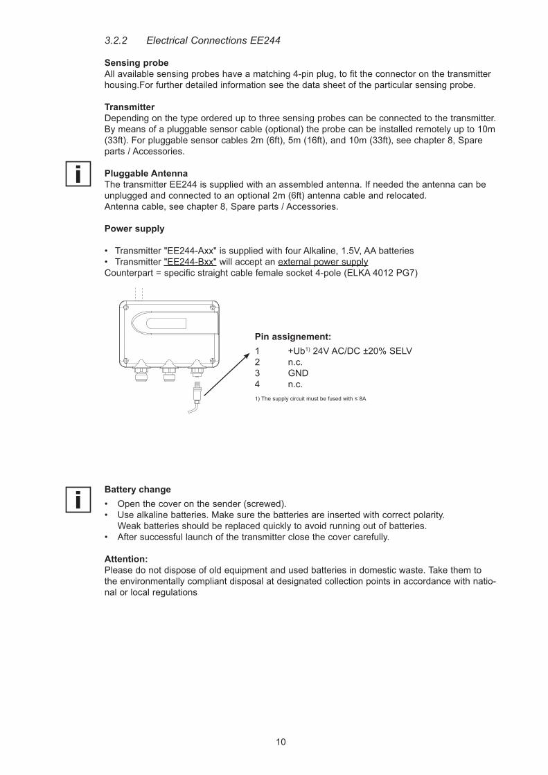
3.2.2 Electrical Connections EE244
Sensing probeAllavailablesensingprobeshaveamatching4-pinplug,tofittheconnectoronthetransmitterhousing.For further detailed information see the data sheet of the particular sensing probe.
TransmitterDepending on the type ordered up to three sensing probes can be connected to the transmitter.By means of a pluggable sensor cable (optional) the probe can be installed remotely up to 10m (33ft). For pluggable sensor cables 2m (6ft), 5m (16ft), and 10m (33ft), see chapter 8, Spare parts / Accessories.
Pluggable AntennaThe transmitter EE244 is supplied with an assembled antenna. If needed the antenna can be unplugged and connected to an optional 2m (6ft) antenna cable and relocated.Antenna cable, see chapter 8, Spare parts / Accessories.
Power supply
• Transmitter "EE244-Axx" is supplied with four Alkaline, 1.5V, AA batteries• Transmitter "EE244-Bxx" will accept an external power supplyCounterpart = specific straight cable female socket 4-pole (ELKA 4012 PG7)
Battery change• Open the cover on the sender (screwed).• Use alkaline batteries. Make sure the batteries are inserted with correct polarity. Weak batteries should be replaced quickly to avoid running out of batteries.• After successful launch of the transmitter close the cover carefully.
Attention:Please do not dispose of old equipment and used batteries in domestic waste. Take them to the environmentally compliant disposal at designated collection points in accordance with natio-nal or local regulations
Pin assignement:1 +Ub1) 24V AC/DC ±20% SELV2 n.c.3 GND4 n.c.1) Thesupplycircuitmustbefusedwith≤8A
11
1. Interval rotary-switch “TIME”:With the rotary switch “TIME”, the following transmission and measurement intervals can be selected:
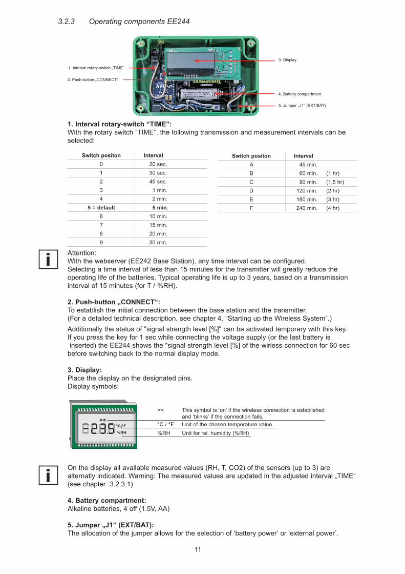
><
>< This symbol is ‘on’ if the wireless connection is established and ‘blinks’ if the connection fails.°C / °F Unit of the chosen temperature value%RH Unit for rel. humidity (%RH)
3.2.3 Operating components EE244
1. Interval rotary-switch „TIME“
4. Battery compartment
2. Push-button „CONNECT“
5. Jumper „J1“ (EXT/BAT)
3. Display
On the display all available measured values (RH, T, CO2) of the sensors (up to 3) are alternatly indicated. Warning: The measured values are updated in the adjusted interval „TIME“ (see chapter 3.2.3.1).
4. Battery compartment: Alkaline batteries, 4 off (1.5V, AA)
5. Jumper „J1“ (EXT/BAT): The allocation of the jumper allows for the selection of ‘battery power’ or ‘external power’.
Switch positon Interval0 20 sec.1 30 sec.2 45 sec.3 1 min.4 2 min.
5 = default 5 min.6 10 min.7 15 min.8 20 min.9 30 min.
Switch positon IntervalA 45 min.B 60 min. (1 hr)C 90 min. (1,5 hr)D 120 min. (2 hr)E 180 min. (3 hr)F 240 min. (4 hr)
Attention:With the webserver (EE242 Base Station), any time interval can be configured. Selecting a time interval of less than 15 minutes for the transmitter will greatly reduce the operating life of the batteries. Typical operating life is up to 3 years, based on a transmission interval of 15 minutes (for T / %RH).
2. Push-button „CONNECT“:To establish the initial connection between the base station and the transmitter. (For a detailed technical description, see chapter 4. “Starting up the Wireless System”.)Additionally the status of "signal strength level [%]" can be activated temporary with this key.If you press the key for 1 sec while connecting the voltage supply (or the last battery is inserted) the EE244 shows the "signal strength level [%] of the wirless connection for 60 sec before switching back to the normal display mode.
3. Display:Place the display on the designated pins. Display symbols:
12
Mounting holesDimensions
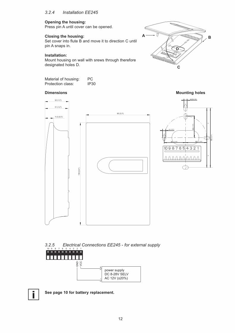
3.2.4 Installation EE245
Opening the housing:Press pin A until cover can be opened.
Closing the housing:Set cover into flute B and move it to direction C until pin A snaps in.
Installation:Mount housing on wall with srews through therefore designated holes D.
Material of housing: PCProtection class: IP30
3.2.5 Electrical Connections EE245 - for external supply
D
B
C
A
85 (3.3“)
11,5 (0.5“)
31 (1.2“)
32 (1.3“)
136
(5.4
“)
power supplyDC 8-28V SELVAC 12V (±20%)
GN
DV
CC
10 9 8 7 6 5 4 3 2 1
See page 10 for battery replacement.
13
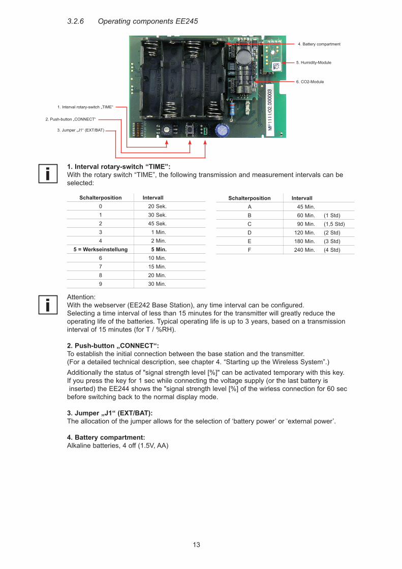
3.2.6 Operating components EE245
1. Interval rotary-switch “TIME”:With the rotary switch “TIME”, the following transmission and measurement intervals can be selected:
Schalterposition Intervall0 20 Sek.1 30 Sek.2 45 Sek.3 1 Min.4 2 Min.
5 = Werkseinstellung 5 Min.6 10 Min.7 15 Min.8 20 Min.9 30 Min.
Schalterposition IntervallA 45 Min.B 60 Min. (1 Std)C 90 Min. (1,5 Std)D 120 Min. (2 Std)E 180 Min. (3 Std)F 240 Min. (4 Std)
Attention:With the webserver (EE242 Base Station), any time interval can be configured. Selecting a time interval of less than 15 minutes for the transmitter will greatly reduce the operating life of the batteries. Typical operating life is up to 3 years, based on a transmission interval of 15 minutes (for T / %RH).
2. Push-button „CONNECT“:To establish the initial connection between the base station and the transmitter. (For a detailed technical description, see chapter 4. “Starting up the Wireless System”.)Additionally the status of "signal strength level [%]" can be activated temporary with this key.If you press the key for 1 sec while connecting the voltage supply (or the last battery is inserted) the EE244 shows the "signal strength level [%] of the wirless connection for 60 sec before switching back to the normal display mode.
3. Jumper „J1“ (EXT/BAT): The allocation of the jumper allows for the selection of ‘battery power’ or ‘external power’.
4. Battery compartment: Alkaline batteries, 4 off (1.5V, AA)
1. Interval rotary-switch „TIME“
2. Push-button „CONNECT“
4. Battery compartment
3. Jumper „J1“ (EXT/BAT)
6. CO2-Module
5. Humidity-Module
14
3.3 Router
The router is designed to increase the overall transmission distance and to bypass obstacles. Each router has the ability to receive and transmit a maximum of 10 signals (transmitter or another router). Sensing probes cannot be connected to the router.
3.3.1 Installation
For the installation of the router, see chapter 3.2.1. Installation of a transmitter.
3.3.2 Electrical Connections
The router is powered by an external power supply. Pin assignment of the female socket, see chapter 3.2.2. Electrical Connection (Transmitter), under “Power Supply”.
3.3.3 Operating Components• Jumper „J1“• Push-button "Connect"
For details refer to chapter 3.2.3 Operating components (Transmitter).
15
4. STARTING UP THE WIRELESS SYSTEM
4.1 “Point-to-Point” (EE241 with a single transmitter)There is no personal computer necessary to configure the EE241 – the desired setup is confi-gured by E+E Elektronik in accordance with the ordering code.Necessary steps to start up the system:1) Establish the power supply to the base station.2) Connect the sensing probe to the transmitter, either direct or with a sensor cable.3) Establish the power supply to the transmitter (4 Alkaline 1.5 V, AA batteries, in the scope
of supply). Remove the transportation insulation-strip in the battery compartment first, to activate the transmitter.
4) Establish the wireless connection: Press the push-button “Connect” for 3 sec.. Immediately the base station switches to the ‘Connect-Mode’ and searches for active transmitters – for 30 sec.. The LED next to the push-button lights up to indicate the ‘Connect-Mode’ is active. Within these 30 sec., the push-button “Connect” on the transmitter must be pressed for 3 sec. to establish a connection. As soon as the base station recognizes the wireless signal from the transmitter, the addresses of the devices are automatically exchanged and the wireless connection established.
5) Checking the active wireless connection: Base station: The wireless connection is active, as soon as the measurement data is available (display, analogue output). Transmitter: The wireless connection is active, as soon as in the display the symbol >< is continuously illuminated (see chapter 3.2.3. Operating Components, under 3. Display).
6) Alterations of the configuration of the transmitter: The transmission interval is set at a default of 5 minutes. To increase the operating life of the batteries the transmission interval can easily be altered with the rotary switch “TIME” in accordance with the interval-time table, see chapter 3.2.3 Operating Components, under 1. Rotary Switch “TIME”.
4.2 “Wireless Network” (EE242 with multiple transmitters)For the configuration of the EE242 a personal computer is needed (with admin authorization), to manage all transmitters and to configure the analogue outputs of the base station.1) Preparing the hardware:
Attention: the base station can handle a maximum of 10 wireless signals (transmitter or router). If more than 10 transmitters are needed, an extra router will extend the network further (for details, see chapter 3.3. Router).
2) Preparing the personal computer and software: No disk space is needed on the personal computer, because the EE242 is equipped with a web server.
3) Configuration of the wireless network: Connect the base station with the personal computer by way of the Ethernet connection and adjust the network settings (see chapter, Configuration Software). - Start the internet browser (Internet Explorer, Firefox, ….). - Enter the default IP-address (//192.168.0.64) of the EE242 in the address line.
4) Check the active wireless connection, see chapter 4.1 “Point–to-Point” (EE241with a single transmitter), under 4).
5) Changing the configuration settings of the transmitter and the base station, see chapter Configuration Software.
4.3 Increasing the Transmission Distance with RoutersIn order to register the transmitter EE244 to the network through the router the following steps have to be taken:a) Register the router:Press the push-button “Connect” on the base station for 3 sec.. Within 30 sec., the push-button “Connect” on the router must be pressed for 3 sec. to establish a connection. As soon as the base station recognizes the wireless signal from the router, transmitters can be added and con-nected through the router.b) Register transmitters to the network through the router:Press the push-button “Connect” on the base station for 3 sec. Within 30 sec., the push-button “Connect” on the transmitter must be pressed for 3 sec. to establish a con-nection. As soon as the base station recognizes the wireless signal from the transmitter, the addresses of the devi-ces are automatically exchanged and the wireless connection established.

16
5. CALIBRATION OF MEASUREMENT SYSTEM
5.1 Calibration of the EE244 Sensing Probes at E+E’s OEKD-Lab
Any of the sensing probes can be sent to E+E’s OEKD-lab for calibration.
5.2 Customer’s Calibration of the Humidity/Temperature Sensing Probes
a) Calibration software on the personal computer:The calibration can be done by means of software on a personal computer→seerespectiveproductdatasheet.
b) For all EE07 sensing probes by use of EE220 transmitter:The calibration of the RH and T outputs is done by means of the calibration buttons on the board of the EE220 humidity/temperature transmitter. For details, see manual EE220 and in chapter 8. Replacement Parts / Accessories.
A humidity calibrator is needed in order to perform an accurate humidity calibration (e.g. E+E’s “Humor 20”, see chapter 8. Replacement Parts / Accessories).
5.3 Functional Test of the Entire Measurement System
It is possible by utilizing reference probes (fixed output value) to test the entire measurement system. A reference probe, available as an accessory (incl. calibration certificate / see chapter 8. Replacement Parts / Accessories), is used to test the function and accuracy of the measurement loop.Both reference probes, with a fixed output value for humidity and temperature, are connected to the transmitter instead of the standard interchangeable sensing probes. The reference probes simulate a high humidity and a low temperature value and vice versa, in order to test the high and low end of the scales of the analogue outputs.
5.4 Loop-Calibration
The loop calibration of the humidity and temperature outputs, as recommended by the FDA for the pharmaceutical and biotech industry, can easily be realized with separate humidity and temperature sensing probes (type EE07). E+E’s “Humor 20” can be utilized as the high accurate humidity calibrator (see chapter 8. Replacement Parts / Accessories).
RH probe T probe
17
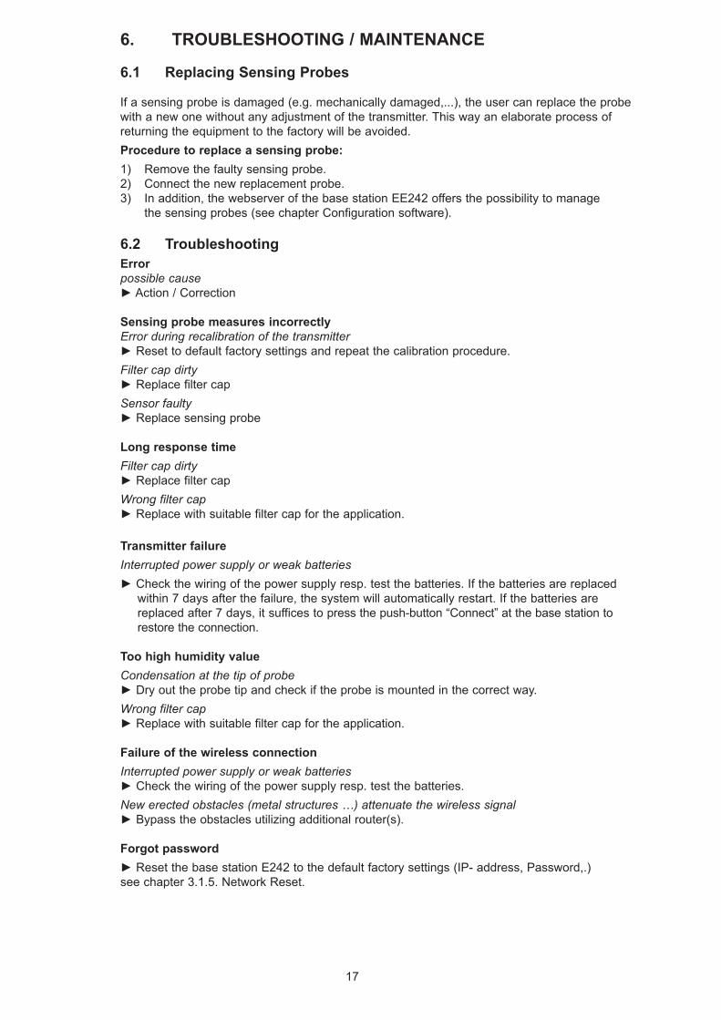
6. TROUBLESHOOTING / MAINTENANCE
6.1 Replacing Sensing Probes
If a sensing probe is damaged (e.g. mechanically damaged,...), the user can replace the probe with a new one without any adjustment of the transmitter. This way an elaborate process of returning the equipment to the factory will be avoided.Procedure to replace a sensing probe:1) Remove the faulty sensing probe.2) Connect the new replacement probe.3) In addition, the webserver of the base station EE242 offers the possibility to manage
the sensing probes (see chapter Configuration software).
6.2 TroubleshootingErrorpossible cause►Action/Correction
Sensing probe measures incorrectlyError during recalibration of the transmitter►Resettodefaultfactorysettingsandrepeatthecalibrationprocedure.Filter cap dirty►ReplacefiltercapSensor faulty►Replacesensingprobe
Long response timeFilter cap dirty►ReplacefiltercapWrong filter cap►Replacewithsuitablefiltercapfortheapplication.
Transmitter failureInterrupted power supply or weak batteries►Checkthewiringofthepowersupplyresp.testthebatteries.Ifthebatteriesarereplaced
within 7 days after the failure, the system will automatically restart. If the batteries are replaced after 7 days, it suffices to press the push-button “Connect” at the base station to restore the connection.
Too high humidity valueCondensation at the tip of probe►Dryouttheprobetipandcheckiftheprobeismountedinthecorrectway.Wrong filter cap►Replacewithsuitablefiltercapfortheapplication.
Failure of the wireless connectionInterrupted power supply or weak batteries►Checkthewiringofthepowersupplyresp.testthebatteries.New erected obstacles (metal structures …) attenuate the wireless signal►Bypasstheobstaclesutilizingadditionalrouter(s).
Forgot password►ResetthebasestationE242tothedefaultfactorysettings(IP-address,Password,.) see chapter 3.1.5. Network Reset.
18
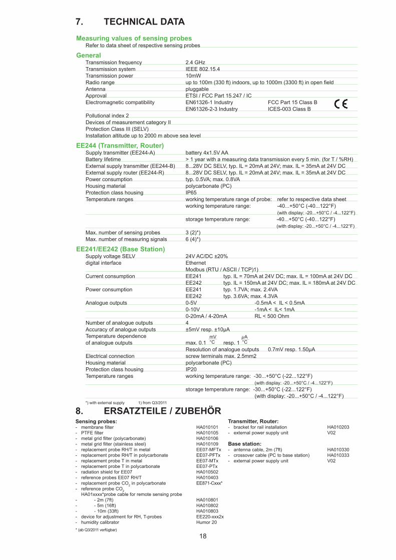
Measuring values of sensing probesRefer to data sheet of respective sensing probes
GeneralTransmission frequency 2.4 GHzTransmission system IEEE 802.15.4 Transmission power 10mW Radiorange upto100m(330ft)indoors,upto1000m(3300ft)inopenfieldAntenna pluggableApproval ETSI / FCC Part 15.247 / ICElectromagnetic compatibility EN61326-1 Industry FCC Part 15 Class B EN61326-2-3 Industry ICES-003 Class BPollutional index 2Devices of measurement category IIProtection Class III (SELV)Installation altitude up to 2000 m above sea level
EE244 (Transmitter, Router)Supply transmitter (EE244-A) battery 4x1.5V AABattery lifetime > 1 year with a measuring data transmission every 5 min. (for T / %RH) External supply transmitter (EE244-B) 8...28V DC SELV, typ. IL = 20mA at 24V; max. IL = 35mA at 24V DCExternal supply router (EE244-R) 8...28V DC SELV, typ. IL = 20mA at 24V; max. IL = 35mA at 24V DCPower consumption typ. 0.5VA; max. 0.8VAHousing material polycarbonate (PC)Protection class housing IP65Temperature ranges working temperature range of probe: refer to respective data sheet working temperature range: -40...+50°C (-40...122°F) (with display: -20...+50°C / -4...122°F) storage temperature range: -40...+50°C (-40...122°F) (with display: -20...+50°C / -4...122°F)Max. number of sensing probes 3 (2)*)Max. number of measuring signals 6 (4)*)
EE241/EE242 (Base Station)Supply voltage SELV 24V AC/DC ±20%digital interface Ethernet Modbus (RTU / ASCII / TCP)1)Current consumption EE241 typ. IL = 70mA at 24V DC; max. IL = 100mA at 24V DC EE242 typ. IL = 150mA at 24V DC; max. IL = 180mA at 24V DCPower consumption EE241 typ. 1.7VA; max. 2.4VA EE242 typ. 3.6VA; max. 4.3VAAnalogue outputs 0-5V -0.5mA < IL < 0.5mA 0-10V -1mA < IL< 1mA 0-20mA / 4-20mA RL < 500 OhmNumber of analogue outputs 4Accuracy of analogue outputs ±5mV resp. ±10µATemperature dependence of analogue outputs max. 0.1 resp. 1 Resolution of analogue outputs 0.7mV resp. 1.50µAElectrical connection screw terminals max. 2.5mm2Housing material polycarbonate (PC)Protection class housing IP20Temperature ranges working temperature range: -30...+50°C (-22...122°F) (with display: -20...+50°C / -4...122°F) storage temperature range: -30...+50°C (-22...122°F) (with display: -20...+50°C / -4...122°F)
*) with external supply 1) from Q3/2011
7. TECHNICAL DATA
8. ERSATZTEILE / ZUBEHÖR
mV°C
µA°C
* (ab Q3/2011 verfügbar)
Sensing probes: - membrane filter HA010101 - PTFE filter HA010105 - metal grid filter (polycarbonate) HA010106 - metal grid filter (stainless steel) HA010109 - replacement probe RH/T in metal EE07-MFTx - replacement probe RH/T in polycarbonate EE07-PFTx - replacement probe T in metal EE07-MTx - replacement probe T in polycarbonate EE07-PTx - radiation shield for EE07 HA010502 - reference probes EE07 RH/T HA010403 - replacement probe CO2 in polycarbonate EE871-Cxxx* - reference probe CO2
HA01xxxx*probe cable for remote sensing probe - - 2m (7ft) HA010801 - - 5m (16ft) HA010802 - - 10m (33ft) HA010803 - device for adjustment for RH, T-probes EE220-xxx2x - humidity calibrator Humor 20
Transmitter, Router: - bracket for rail installation HA010203 - external power supply unit V02
Base station: - antenna cable, 2m (7ft) HA010330 - crossover cable (PC to base station) HA010333 - external power supply unit V02
19
CONFIGURATION SOFTWARELIMITED LIABILITYE+E Elektronik® is not liable for any direct or consequential damages (for example, but not restricted to loss of earnings, interruption of business, loss of information and data or any other financial losses), which result from the installation, usage and also impossibility of usage of a software product from E+E Elektronik® and any associated support or non-performance of support.
11.2 Setup of IP-address
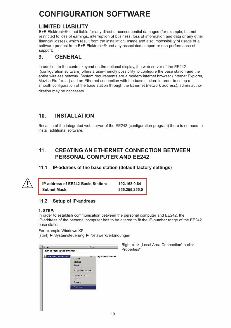
1. STEP:In order to establish communication between the personal computer and EE242, the IP-address of the personal computer has to be altered to fit the IP-number range of the EE242 base station.For example Windows XP:[start]►Systemsteuerung►Netzwerkverbindungen
IP-address of EE242-Basis Station: 192.168.0.64Subnet Mask: 255.255.255.0
Right-click „Local Area Connection“ a click Properties"
9. GENERALIn addition to the control keypad on the optional display, the web-server of the EE242 (configuration software) offers a user-friendly possibility to configure the base station and the entire wireless network. System requirements are a modern internet browser (Internet Explorer, Mozilla Firefox …) and an Ethernet connection with the base station. In order to setup a smooth configuration of the base station through the Ethernet (network address), admin autho-rization may be necessary.
10. INSTALLATIONBecause of the integrated web server of the EE242 (configuration program) there is no need to install additional software.
11. CREATING AN ETHERNET CONNECTION BETWEEN PERSONAL COMPUTER AND EE242
11.1 IP-address of the base station (default factory settings)
20
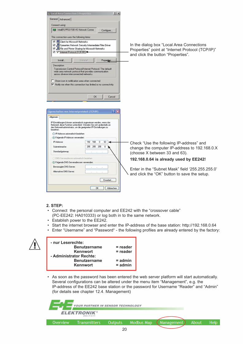
In the dialog box “Local Area Connections Properties” point at “Internet Protocol (TCP/IP)” and click the button “Properties”.
Check “Use the following IP-address” and change the computer IP-address to 192.168.0.X (choose X between 33 and 63).192.168.0.64 is already used by EE242!
Enter in the “Subnet Mask” field ‘255.255.255.0’ and click the “OK” button to save the setup.
2. STEP:• Connect the personal computer and EE242 with the “crossover cable”
(PC-EE242: HA010333) or log both in to the same network. • Establish power to the EE242.• Start the internet browser and enter the IP-address of the base station: http://192.168.0.64• Enter “Username” and “Password“ - the following profiles are already entered by the factory:
• As soon as the password has been entered the web server platform will start automatically. Several configurations can be altered under the menu item “Management”, e.g. the IP-address of the EE242 base station or the password for Username “Reader” and “Admin” (for details see chapter 12.4. Management)
- nur Leserechte: Benutzername = reader Kennwort = reader- Administrator Rechte: Benutzername = admin Kennwort = admin
21
12. MENU ITEMS
12.1 Overview
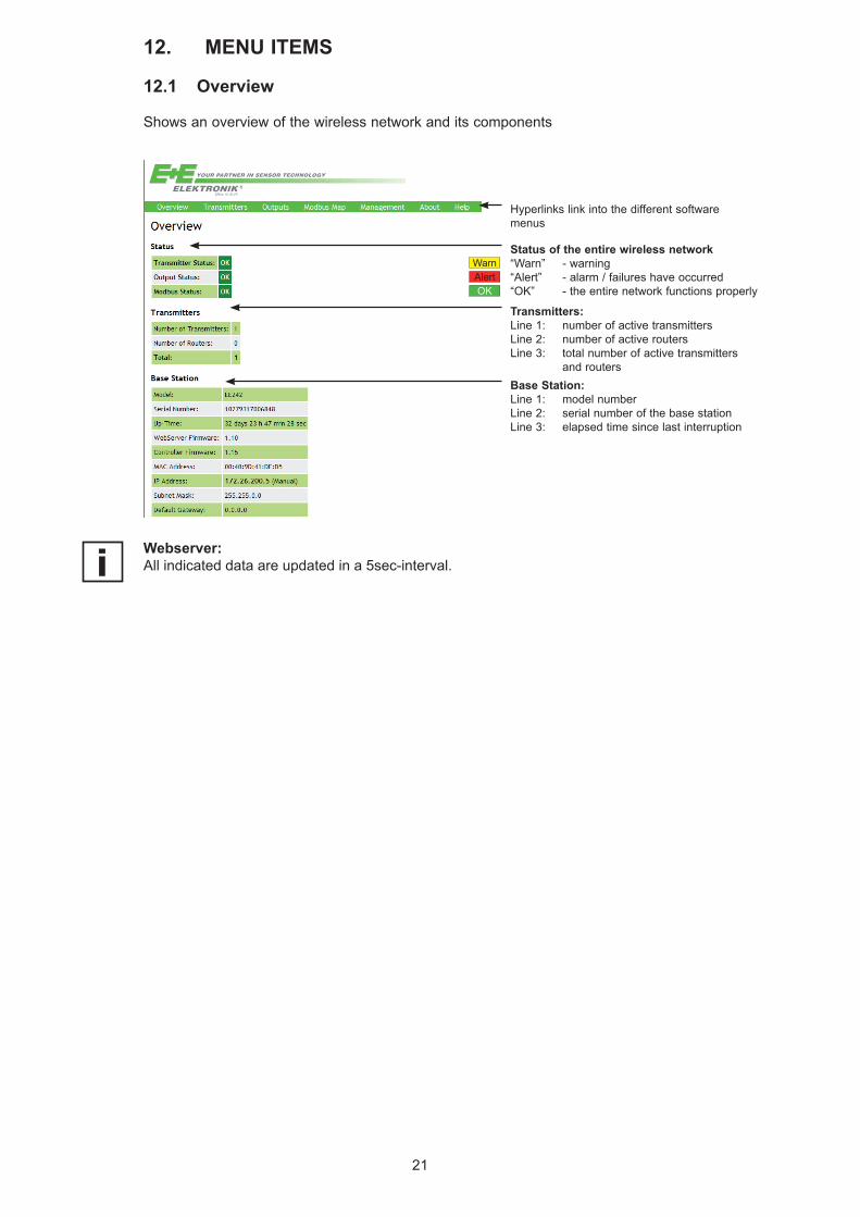
Shows an overview of the wireless network and its components
Status of the entire wireless network“Warn” - warning“Alert” - alarm / failures have occurred“OK” - the entire network functions properly
Hyperlinks link into the different software menus
WarnAlertOK
Transmitters:Line 1: number of active transmittersLine 2: number of active routersLine 3: total number of active transmitters and routersBase Station:Line 1: model numberLine 2: serial number of the base stationLine 3: elapsed time since last interruption
Webserver:All indicated data are updated in a 5sec-interval.
22
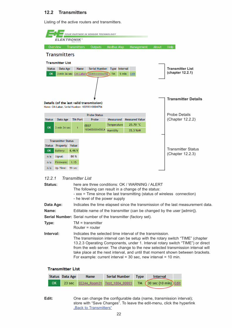
12.2 Transmitters
Listing of the active routers and transmitters.
Transmitter List (chapter 12.2.1)
Probe Details (Chapter 12.2.2)
Transmitter Status (Chapter 12.2.3)
12.2.1 Transmitter ListStatus: here are three conditions: OK / WARNING / ALERT The following can result in a change of the status: - xxx = Time since the last transmitting (status of wireless connection) - he level of the power supplyData Age: Indicates the time elapsed since the transmission of the last measurement data.Name: Editable name of the transmitter (can be changed by the user [admin]). Serial Number: Serial number of the transmitter (factory set).Type: TM = transmitter Router = routerInterval: Indicates the selected time interval of the transmission. The transmission interval can be setup with the rotary switch “TIME” (chapter 13.2.3 Operating Components, under 1. Interval rotary switch “TIME”) or direct from the web server. The change to the new selected transmission interval will take place at the next interval, and until that moment shown between brackets. For example: current interval = 30 sec, new interval = 10 min.
Transmitter Details
Edit: Onecanchangetheconfigurabledata(name,transmissioninterval); store with “Save Changes”. To leave the edit-menu, click the hyperlink „Back to Transmitters“
23
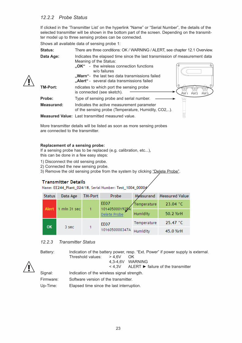
12.2.2 Probe Status
If clicked in the ‘Transmitter List’ on the hyperlink “Name” or “Serial Number”, the details of the selected transmitter will be shown in the bottom part of the screen. Depending on the transmit-ter model up to three sensing probes can be connected.Shows all available data of sensing probe 1:Status: There are three conditions: OK / WARNING / ALERT, see chapter 12.1 Overview.Data Age: Indicates the elapsed time since the last transmission of measurement data Meaning of the Status: „OK“ - the wireless connection functions w/o failures „Warn“ - the last two data transmissions failed „Alert“ - several data transmissions failedTM-Port: ndicates to which port the sensing probe is connected (see sketch). Probe: Type of sensing probe and serial number.Measurand: Indicates the active measurement parameter of the sensing probe (Temperature, Humidity, CO2,..).Measured Value: Last transmitted measured value.
More transmitter details will be listed as soon as more sensing probes are connected to the transmitter.
Replacement of a sensing probe:If a sensing probe has to be replaced (e.g. calibration, etc...), this can be done in a few easy steps:1) Disconnect the old sensing probe.2) Connected the new sensing probe.3) Remove the old sensing probe from the system by clicking “Delete Probe”.
Port 1 Port 2 Port 3
12.2.3 Transmitter Status
Battery: Indication of the battery power, resp. “Ext. Power” if power supply is external. Threshold values: > 4,6V OK 4,3-4,6V WARNING <4,3V ALERT►failure of the transmitterSignal: Indication of the wireless signal strength.Firmware: Software version of the transmitter.Up-Time: Elapsed time since the last interruption.
24
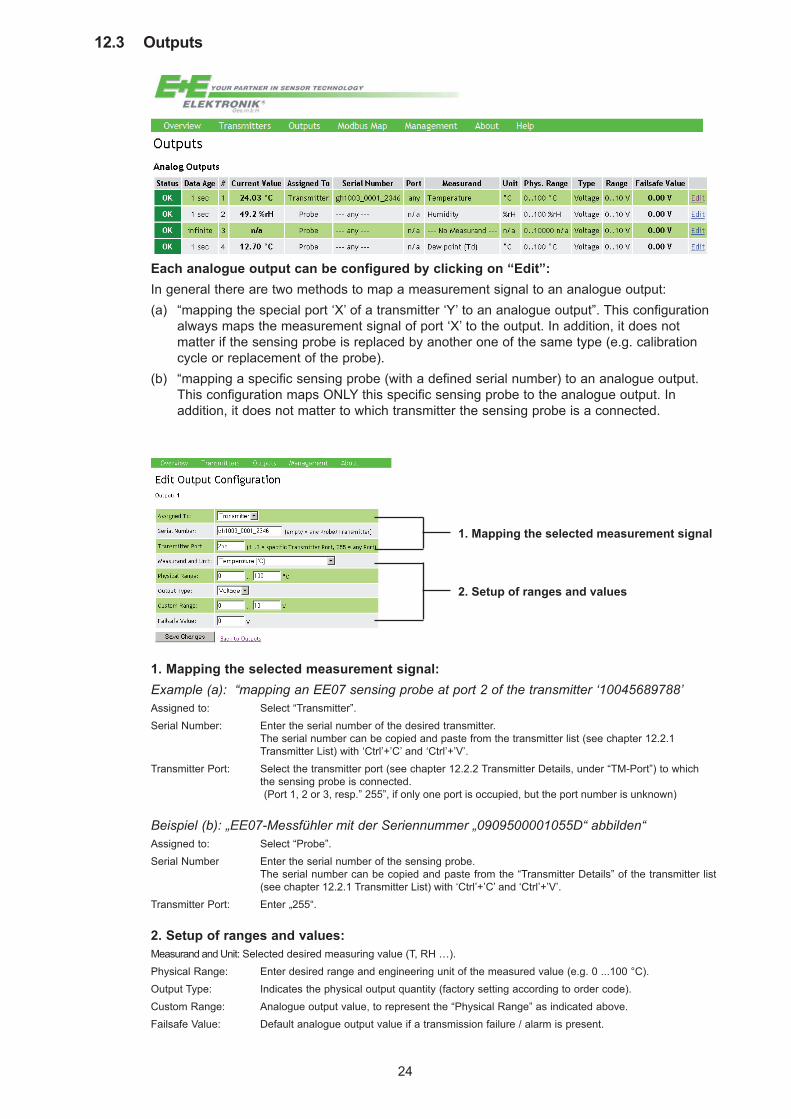
12.3 Outputs
Each analogue output can be configured by clicking on “Edit”:In general there are two methods to map a measurement signal to an analogue output:(a) “mapping the special port ‘X’ of a transmitter ‘Y’ to an analogue output”. This configuration always maps the measurement signal of port ‘X’ to the output. In addition, it does not matter if the sensing probe is replaced by another one of the same type (e.g. calibration cycle or replacement of the probe).(b) “mapping a specific sensing probe (with a defined serial number) to an analogue output. This configuration maps ONLY this specific sensing probe to the analogue output. In addition, it does not matter to which transmitter the sensing probe is a connected.
1. Mapping the selected measurement signal
2. Setup of ranges and values
1. Mapping the selected measurement signal:Example (a): “mapping an EE07 sensing probe at port 2 of the transmitter ‘10045689788’Assigned to: Select “Transmitter”. Serial Number: Enter the serial number of the desired transmitter. The serial number can be copied and paste from the transmitter list (see chapter 12.2.1 Transmitter List) with ‘Ctrl’+’C’ and ‘Ctrl’+’V’. Transmitter Port: Select the transmitter port (see chapter 12.2.2 Transmitter Details, under “TM-Port”) to which the sensing probe is connected. (Port 1, 2 or 3, resp.” 255”, if only one port is occupied, but the port number is unknown)
Beispiel (b): „EE07-Messfühler mit der Seriennummer „0909500001055D“ abbilden“Assigned to: Select “Probe”.Serial Number Enter the serial number of the sensing probe. The serial number can be copied and paste from the “Transmitter Details” of the transmitter list (see chapter 12.2.1 Transmitter List) with ‘Ctrl’+’C’ and ‘Ctrl’+’V’.Transmitter Port: Enter „255“.
2. Setup of ranges and values:Measurand and Unit: Selected desired measuring value (T, RH …).Physical Range: Enter desired range and engineering unit of the measured value (e.g. 0 ...100 °C).Output Type: Indicates the physical output quantity (factory setting according to order code).Custom Range: Analogue output value, to represent the “Physical Range” as indicated above.Failsafe Value: Default analogue output value if a transmission failure / alarm is present.
25
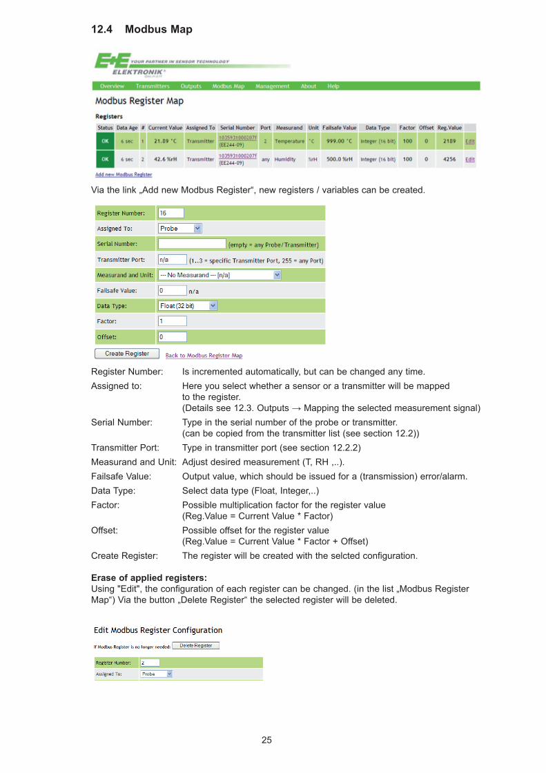
12.4 Modbus Map
Register Number: Is incremented automatically, but can be changed any time.Assigned to: Here you select whether a sensor or a transmitter will be mapped to the register. (Detailssee12.3.Outputs→Mappingtheselectedmeasurementsignal)Serial Number: Type in the serial number of the probe or transmitter. (can be copied from the transmitter list (see section 12.2)) Transmitter Port: Type in transmitter port (see section 12.2.2)Measurand and Unit: Adjust desired measurement (T, RH ,..).Failsafe Value: Output value, which should be issued for a (transmission) error/alarm.Data Type: Select data type (Float, Integer,..)Factor: Possible multiplication factor for the register value (Reg.Value = Current Value * Factor)Offset: Possible offset for the register value (Reg.Value = Current Value * Factor + Offset)Create Register: The register will be created with the selcted configuration.
Erase of applied registers:Using "Edit", the configuration of each register can be changed. (in the list „Modbus Register Map“) Via the button „Delete Register“ the selected register will be deleted.
Via the link „Add new Modbus Register“, new registers / variables can be created.
26
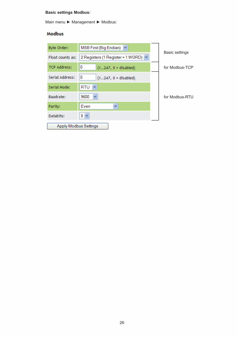
Basic settings Modbus:
Mainmenu►Management►Modbus:
Basic settings
for Modbus-TCP
for Modbus-RTU
27
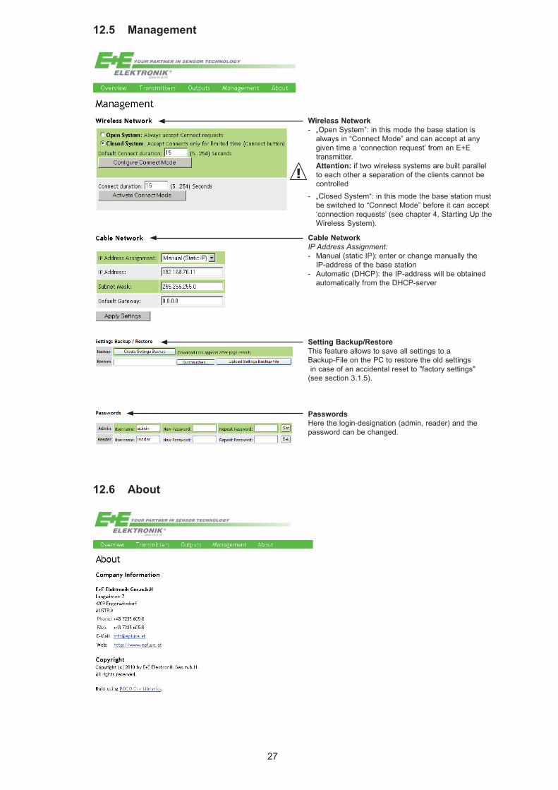
12.5 Management
Wireless Network- „Open System”: in this mode the base station is always in “Connect Mode” and can accept at any given time a ‘connection request’ from an E+E transmitter. Attention: if two wireless systems are built parallel to each other a separation of the clients cannot be controlled- „Closed System“: in this mode the base station must be switched to “Connect Mode” before it can accept ‘connection requests’ (see chapter 4, Starting Up the Wireless System).
Cable NetworkIP Address Assignment:- Manual (static IP): enter or change manually the IP-address of the base station- Automatic (DHCP): the IP-address will be obtained automatically from the DHCP-server
PasswordsHere the login-designation (admin, reader) and the password can be changed.
Setting Backup/RestoreThis feature allows to save all settings to a Backup-File on the PC to restore the old settings in case of an accidental reset to "factory settings" (see section 3.1.5).
12.6 About

HEAD OFFICE:
E+E ELEKTRONIK Ges.m.b.H.Langwiesen 7A-4209 EngerwitzdorfAustriaTel: +43 7235 605 0Fax: +43 7235 605 [email protected]
SALES OFFICES:
E+E CHINA / BEIJINGTel: +86 10 [email protected] www.epluse.cn
E+E CHINA / SHANGHAITel: +86 21 [email protected] www.epluse.cn
E+E GERMANYTel: +49 6172 13881 [email protected] www.epluse.de
E+E FRANCETel: +33 4 7472 35 [email protected] www.epluse.fr
E+E ITALYTel: +39 0331 177 31 02 [email protected] www.epluse.it
E+E KOREATel: +82 31 732 [email protected] www.epluse.co.kr
E+E USATel: +1 781 828 [email protected] www.epluse.com