Embed Size (px)
Citation preview
A
G.2
B
C
D
E
F
G
H
I
X
Lim
it sw
itch
esSeries IS and IM
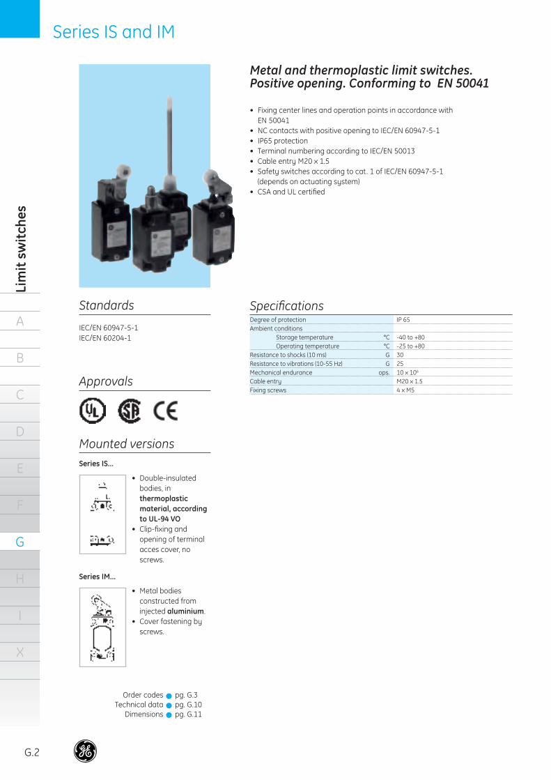
Metal and thermoplastic limit switches. Positive opening. Conforming to EN 50041
• Fixing center lines and operation points in accordance with EN 50041• NC contacts with positive opening to IEC/EN 60947-5-1• IP65 protection• Terminal numbering according to IEC/EN 50013• Cable entry M20 x 1.5• Safety switches according to cat. 1 of IEC/EN 60947-5-1 (depends on actuating system)• CSA and UL certifi ed
Standards Specifi cations
Approvals
Degree of protection IP 65Ambient conditions Storage temperature °C -40 to +80 Operating temperature °C -25 to +80 Resistance to shocks (10 ms) G 30 Resistance to vibrations (10-55 Hz) G 25Mechanical endurance ops. 10 x 106
Cable entry M20 x 1.5Fixing screws 4 x M5
Series IS...
Series IM...
Order codesTechnical data
Dimensions
pg. G.3pg. G.10pg. G.11
!!!
IEC/EN 60947-5-1IEC/EN 60204-1
Mounted versions
• Metal bodies constructed from injected aluminium.
• Cover fastening by screws.
• Double-insulated bodies, in thermoplastic material, according to UL-94 VO
• Clip-fi xing and opening of terminal acces cover, no screws.
39584_G01_G09_E.indd 2 18-09-2007 12:09:02

Series IS and IM
A
B
C
D
E
F
G
H
I
X
Order codes
G.3
Limit switches according to EN 50041
Heads Head Form to Cat.no Ref. no. Cat.no Ref. no. Pack Standard position position EN 50041
Slow break Snap action
I I I I I
Omnidirectional I I I (1) ISGM-B311 130040 5 spring rod (2) I I I (1) IMGM-B311 130041 5
Roller plunger I I I C ISGR-B411 130020 5 I I I C IMGR-B411 130021 5
Roller level I I I (1) ISGH-B411 130022 5 I I I (1) IMGH-B411 130023 5
Roller crank I I I A ISGL-B411 130028 5 I I I A IMGL-B411(4) 130029 5
Adjustable roller I I (1) ISGT-B311 130030 5 crank (2) I I (1) IMGT-B311 130031 5
Rod lever (2) I I D IMGP-B311 130035 5
Cross rod I I (1) IMGC-B411 130037 5
Spring rod lever (2) I I I (1) IMGQ-B311 130039 5
(1) Fixing center lines and operation points in accordance with EN 50041.(2) Heads for these limit switches have no positive opening, as they are adjustable or fl exible.(3) Supplied in standard mounting position. Positions II and III must be set by user.(4) Available with metal roller lever: IMGL-B411M (130107).
Positive break
Mounting position of the head (3)
Plunger I I I B ISGA-B211 130000 ISGA-B411 130018 5 I I I B IMGA-B411 130019 5
39584_G01_G09_E.indd 3 18-09-2007 12:09:03
A
G.4
B
C
D
E
F
G
H
I
X
Lim
it sw
itch
esSeries IUG
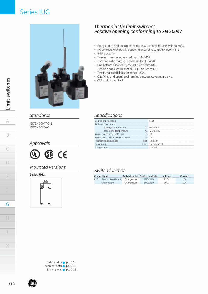
Thermoplastic limit switches. Positive opening conforming to EN 50047
• Fixing center and operation points (IUG...) in accordance with EN 50047• NC contacts with positive opening according to IEC/EN 60947-5-1• IP65 protection• Terminal numbering according to EN 50013• Thermoplastic material according to UL-94 V0• One bottom cable entry M20x1,5 on Series IUG...
Two side cable entries for M16x1,5 on Series IUC.• Two fi xing possibilities for series IUGA... • Clip fi xing and opening of terminals access cover, no screws.• CSA and UL certifi ed
Standards Specifi cations
Approvals
Degree of protection IP 65Ambient conditions Storage temperature °C -40 to +80 Operating temperature °C -25 to +80 Resistance to shocks (10 ms) G 30 Resistance to vibrations (10-55 Hz) G 25Mechanical endurance ops. 10 x 106
Cable entry IUG... 1 x (M20x1.5)Fixing screws 2 of M5
Series IUG...
Order codesTechnical data
Dimensions
pg. G.5pg. G.10pg. G.13
!!!
Switch functionContact type Switch function Switch contacts Voltage CurrentIUG Slow make & break Changeover 1NC/1NO 250V 10A Snap action Changeover 1NC/1NO 250V 10A
Mounted versions
IEC/EN 60947-5-1IEC/EN 60204-1
39584_G01_G09_E.indd 4 18-09-2007 12:09:04
A
B
C
D
E
F
G
H
I
X
Order codes
G.5
Series IUG
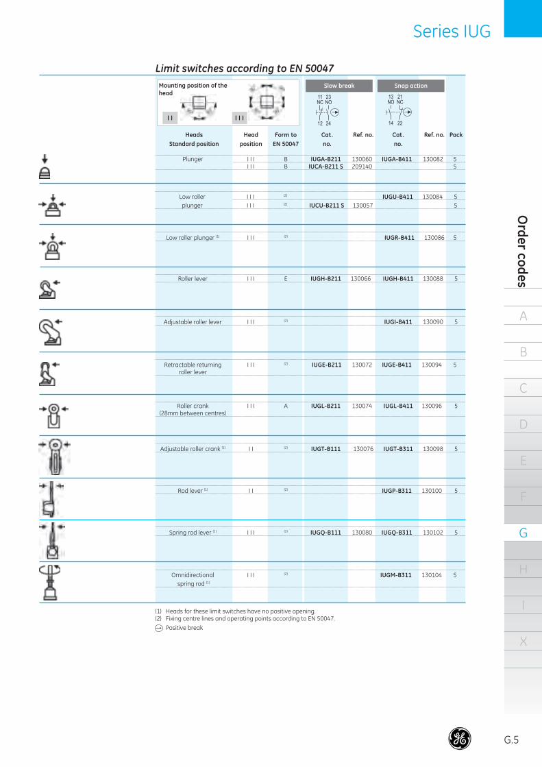
Limit switches according to EN 50047
Heads Head Form to Cat. Ref. no. Cat. Ref. no. Pack Standard position position EN 50047 no. no.
Slow break Snap action
I I
Omnidirectional I I I (2) IUGM-B311 130104 5 spring rod (1)
Plunger I I I B IUGA-B211 130060 IUGA-B411 130082 5 I I I B IUCA-B211 S 209140 5
Low roller I I I (2) IUGU-B411 130084 5 plunger I I I (2) IUCU-B211 S 130057 5
Low roller plunger (1) I I I (2) IUGR-B411 130086 5
Roller lever I I I E IUGH-B211 130066 IUGH-B411 130088 5
Adjustable roller lever I I I (2) IUGI-B411 130090 5
Retractable returning I I I (2) IUGE-B211 130072 IUGE-B411 130094 5 roller lever
Roller crank I I I A IUGL-B211 130074 IUGL-B411 130096 5 (28mm between centres)
Adjustable roller crank (1) I I (2) IUGT-B111 130076 IUGT-B311 130098 5
Rod lever (1) I I (2) IUGP-B311 130100 5
Spring rod lever (1) I I I (2) IUGQ-B111 130080 IUGQ-B311 130102 5
(1) Heads for these limit switches have no positive opening.(2) Fixing centre lines and operating points according to EN 50047.
Mounting position of the head
I I I
Positive break
39584_G01_G09_E.indd 5 18-09-2007 12:09:05
A
G.6
B
C
D
E
F
G
H
I
X
Lim
it sw
itch
esSeries IZ
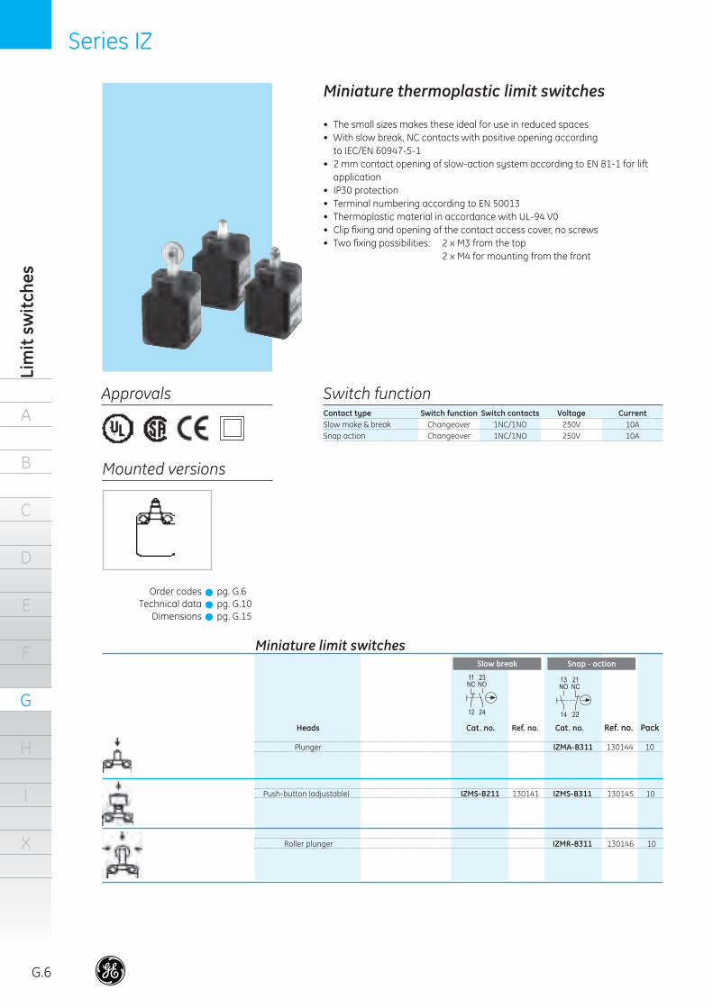
Miniature thermoplastic limit switches
• The small sizes makes these ideal for use in reduced spaces• With slow break, NC contacts with positive opening according
to IEC/EN 60947-5-1• 2 mm contact opening of slow-action system according to EN 81-1 for lift
application• IP30 protection• Terminal numbering according to EN 50013• Thermoplastic material in accordance with UL-94 V0• Clip fi xing and opening of the contact access cover, no screws• Two fi xing possibilities: 2 x M3 from the top 2 x M4 for mounting from the front
Approvals
Mounted versions
Switch functionContact type Switch function Switch contacts Voltage CurrentSlow make & break Changeover 1NC/1NO 250V 10ASnap action Changeover 1NC/1NO 250V 10A
Miniature limit switches
Heads Cat. no. Ref. no. Cat. no. Ref. no. Pack
Slow break Snap - action
Plunger IZMA-B311 130144 10
Push-button (adjustable) IZMS-B211 130141 IZMS-B311 130145 10
Roller plunger IZMR-B311 130146 10
Order codesTechnical data
Dimensions
pg. G.6pg. G.10pg. G.15
!!!
39584_G01_G09_E.indd 6 18-09-2007 12:09:05
Series IZ
A
B
C
D
E
F
G
H
I
X
Order codes
G.7
Notes
. . . . . . . . . . . . . . . . . . . . . . . . . . . . . . . . . . . . . .
. . . . . . . . . . . . . . . . . . . . . . . . . . . . . . . . . . . . . .
. . . . . . . . . . . . . . . . . . . . . . . . . . . . . . . . . . . . . .
. . . . . . . . . . . . . . . . . . . . . . . . . . . . . . . . . . . . . .
. . . . . . . . . . . . . . . . . . . . . . . . . . . . . . . . . . . . . .
. . . . . . . . . . . . . . . . . . . . . . . . . . . . . . . . . . . . . .
. . . . . . . . . . . . . . . . . . . . . . . . . . . . . . . . . . . . . .
. . . . . . . . . . . . . . . . . . . . . . . . . . . . . . . . . . . . . .
. . . . . . . . . . . . . . . . . . . . . . . . . . . . . . . . . . . . . .
. . . . . . . . . . . . . . . . . . . . . . . . . . . . . . . . . . . . . .
. . . . . . . . . . . . . . . . . . . . . . . . . . . . . . . . . . . . . .
. . . . . . . . . . . . . . . . . . . . . . . . . . . . . . . . . . . . . .
. . . . . . . . . . . . . . . . . . . . . . . . . . . . . . . . . . . . . .
. . . . . . . . . . . . . . . . . . . . . . . . . . . . . . . . . . . . . .
. . . . . . . . . . . . . . . . . . . . . . . . . . . . . . . . . . . . . .
. . . . . . . . . . . . . . . . . . . . . . . . . . . . . . . . . . . . . .
. . . . . . . . . . . . . . . . . . . . . . . . . . . . . . . . . . . . . .
. . . . . . . . . . . . . . . . . . . . . . . . . . . . . . . . . . . . . .
. . . . . . . . . . . . . . . . . . . . . . . . . . . . . . . . . . . . . .
. . . . . . . . . . . . . . . . . . . . . . . . . . . . . . . . . . . . . .
. . . . . . . . . . . . . . . . . . . . . . . . . . . . . . . . . . . . . .
. . . . . . . . . . . . . . . . . . . . . . . . . . . . . . . . . . . . . .
. . . . . . . . . . . . . . . . . . . . . . . . . . . . . . . . . . . . . .
. . . . . . . . . . . . . . . . . . . . . . . . . . . . . . . . . . . . . .
. . . . . . . . . . . . . . . . . . . . . . . . . . . . . . . . . . . . . .
. . . . . . . . . . . . . . . . . . . . . . . . . . . . . . . . . . . . . .
. . . . . . . . . . . . . . . . . . . . . . . . . . . . . . . . . . . . . .
. . . . . . . . . . . . . . . . . . . . . . . . . . . . . . . . . . . . . .
. . . . . . . . . . . . . . . . . . . . . . . . . . . . . . . . . . . . . .
. . . . . . . . . . . . . . . . . . . . . . . . . . . . . . . . . . . . . .
. . . . . . . . . . . . . . . . . . . . . . . . . . . . . . . . . . . . . .
. . . . . . . . . . . . . . . . . . . . . . . . . . . . . . . . . . . . . .
. . . . . . . . . . . . . . . . . . . . . . . . . . . . . . . . . . . . . .
. . . . . . . . . . . . . . . . . . . . . . . . . . . . . . . . . . . . . .
. . . . . . . . . . . . . . . . . . . . . . . . . . . . . . . . . . . . . .
. . . . . . . . . . . . . . . . . . . . . . . . . . . . . . . . . . . . . .
. . . . . . . . . . . . . . . . . . . . . . . . . . . . . . . . . . . . . .
. . . . . . . . . . . . . . . . . . . . . . . . . . . . . . . . . . . . . .
. . . . . . . . . . . . . . . . . . . . . . . . . . . . . . . . . . . . . .
. . . . . . . . . . . . . . . . . . . . . . . . . . . . . . . . . . . . . .
. . . . . . . . . . . . . . . . . . . . . . . . . . . . . . . . . . . . . .
. . . . . . . . . . . . . . . . . . . . . . . . . . . . . . . . . . . . . .
. . . . . . . . . . . . . . . . . . . . . . . . . . . . . . . . . . . . . .
. . . . . . . . . . . . . . . . . . . . . . . . . . . . . . . . . . . . . .
. . . . . . . . . . . . . . . . . . . . . . . . . . . . . . . . . . . . . .
. . . . . . . . . . . . . . . . . . . . . . . . . . . . . . . . . . . . . .
. . . . . . . . . . . . . . . . . . . . . . . . . . . . . . . . . . . . . .
. . . . . . . . . . . . . . . . . . . . . . . . . . . . . . . . . . . . . .
39584_G01_G09_E.indd 7 18-09-2007 12:09:07
A
G.8
B
C
D
E
F
G
H
I
X
Lim
it sw
itch
esSeries 114FCT
Climatic protections Temperate climate (DIN 50014) 23 / 50 Wet climate (DIN 50015) 23 / 83 Hot wet climate (DIN 50015) 40 / 92 Variable wet climate (DIN 50016) FW 24Temperature ranges Operation -25ºC to +70ºC Storage -40ºC to +70ºCVibrations resistance 10G(according to IEC 68-2-6) with frequency range from 1 to 100HzMechanical endurance 10 x 106 operationsOperation speed Min. 0.25 m/sec. Max. 1 m/sec.Electrical performances
Capacity min. 22 AWG (0.32mm2)Rigid and/or fl exible conductors max. 12 AWG (3.3mm2)Cable entry 1 x PG11
Terminals
Mechanical performances
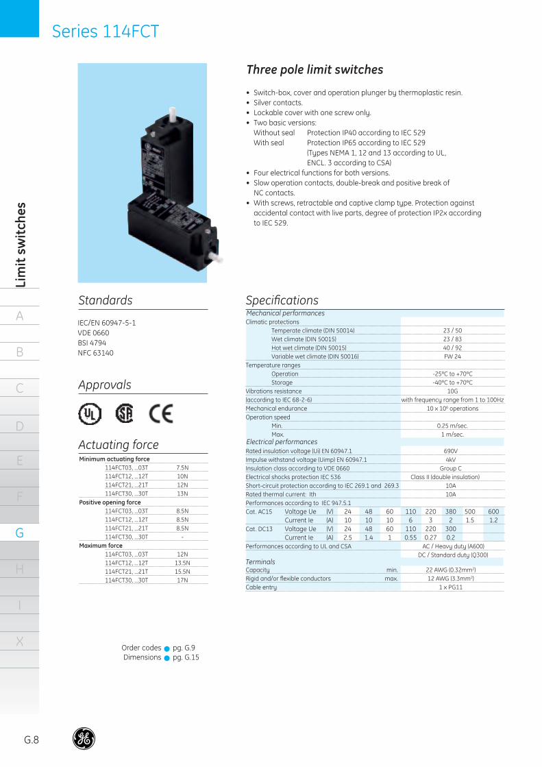
Three pole limit switches
• Switch-box, cover and operation plunger by thermoplastic resin.• Silver contacts.• Lockable cover with one screw only.• Two basic versions: Without seal Protection IP40 according to IEC 529 With seal Protection IP65 according to IEC 529 (Types NEMA 1, 12 and 13 according to UL,
ENCL. 3 according to CSA)• Four electrical functions for both versions.• Slow operation contacts, double-break and positive break of
NC contacts.• With screws, retractable and captive clamp type. Protection against
accidental contact with live parts, degree of protection IP2x according to IEC 529.
Standards Specifi cations
IEC/EN 60947-5-1VDE 0660BSI 4794NFC 63140
Approvals
Minimum actuating force 114FCT03, ...03T 7.5N 114FCT12, ...12T 10N 114FCT21, ...21T 12N 114FCT30, ...30T 13NPositive opening force 114FCT03, ...03T 8.5N 114FCT12, ...12T 8.5N 114FCT21, ...21T 8.5N 114FCT30, ...30T -Maximum force 114FCT03, ...03T 12N 114FCT12, ...12T 13.5N 114FCT21, ...21T 15.5N 114FCT30, ...30T 17N
Actuating force
Order codesDimensions
pg. G.9pg. G.15
!!
Rated insulation voltage (Ui) EN 60947.1 690VImpulse withstand voltage (Uimp) EN 60947.1 4kVInsulation class according to VDE 0660 Group CElectrical shocks protection IEC 536 Class II (double insulation)Short-circuit protection according to IEC 269.1 and 269.3 10ARated thermal current: Ith 10APerformances according to IEC 947.5.1Cat. AC15 Voltage Ue (V) 24 48 60 110 220 380 500 600 Current Ie (A) 10 10 10 6 3 2 1.5 1.2Cat. DC13 Voltage Ue (V) 24 48 60 110 220 300 Current Ie (A) 2.5 1.4 1 0.55 0.27 0.2Performances according to UL and CSA AC / Heavy duty (A600) DC / Standard duty (Q300)
39584_G01_G09_E.indd 8 18-09-2007 12:09:07
Series 114FCT
A
B
C
D
E
F
G
H
I
X
Order codes
G.9
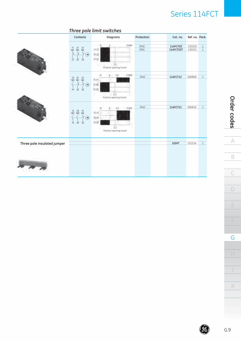
Three pole limit switches Contacts Diagrams Protection Cat. no. Ref. no. Pack. IP40 114FCT03 130320 1 IP65 114FCT03T 130321 1
Positive opening travel
Positive opening travel
IP40 114FCT12 200909 1
Positive opening travel
Three pole insulated jumper
IP40 114FCT21 200910 1
105PT 132234 1
39584_G01_G09_E.indd 9 18-09-2007 12:09:08

A
G.10
B
C
D
E
F
G
H
I
X
Lim
it sw
itch
esSeries IS, IM, IUG, IZ
Technical data
ISG..-B211 ISG..-B311 IUG..-B111 IUG..-B311 IZM..-B211 IZM..-B311 IMG..-B211 IMG..-B311 IUG..-B211 IUG..-B411 ISG..-B411 IMG..-411
Limit switches
Rated insulation voltage (Ui) V
Protection against electrical shocks Protection against electrical shocks (fuse) (A)Rated current (DIN EN60947-5-1) A300 AC-15 12/24V (A) 48/60V (A) (110V) 120V (A) 127V (A) (220V) 240V (A) 380V (A) Q300 DC-13 24V (A) 48V (A) (110V) 125V (A) (220V) 250V (A) 300V (A)Operating rate ops./hSwitching time (ms)Repetition assurance (mm)Clamping capacity (mm2)Terminal screwProtection
Type of break Slow break Snap action Slow break Snap action Slow break Snap actionNumber of contacts 2 2 2 2 2 2 Function 1NO-1NC 1NO-1NC 1NO-1NC 1NO-1NC 1NO-1NC 1NO-1NC Polarity Same Same Same Same Same Same Rated thermal current (Ithe) (A) 10 10 10 10 10 10
380
-
6
--6-3---
0.550.27
-6000
-± 0.11.5
M3.5IP30
250
-
6
--6-3---
0.550.27
-6000
10± 0.11.5
M3.5IP30
250
Class II
10
--6-3------
6000-
± 0.11.5
M3.5IP65
250
Class II
2
--6-3------
600010
± 0.11.5
M3.5IP65
400
Class II (ISG)CLASS I (IMG)
10
--6-3---
0.550.27
-6000
-± 0.1
0.5 - 1.5M3.5IP65
400
Class II (ISG)CLASS I (IMG)
2
--6-3---
0.550.27
-6000
10± 0.11.5
M3.5IP65
Auxiliary contacts
39584_G10_G15_E.indd 10 18-09-2007 12:09:32

Series IS and IM
A
B
C
D
E
F
G
H
I
X
Dim
ensions
G.11
Dimensional drawings
Common for all limit switches Series IS Common for all limit switches Series IM
ISGA B..., IMGA B... ISGH B..., IMGH B...
ISGR B..., IMGR B...
Contact block Series IS
Operating heads
Contact block Series IM
39584_G10_G15_E.indd 11 18-09-2007 12:09:33
A
G.12
B
C
D
E
F
G
H
I
X
Lim
it sw
itch
esSeries IS and IM
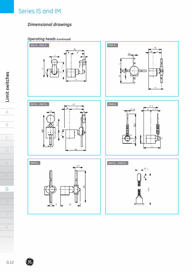
ISGT B..., IMGT B...
IMGP B... ISGM B..., IMGM B...
IMGC B...
IMGQ B...
ISGL B..., IMGL B...
Operating heads (continued)
Dimensional drawings
39584_G10_G15_E.indd 12 18-09-2007 12:09:33
A
B
C
D
E
F
G
H
I
X
Dim
ensions
G.13
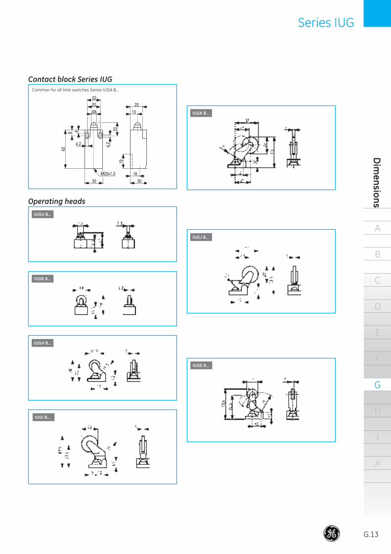
Series IUG
IUGE B...
IUGU B...
IUGR B...
IUGH B...
IUGI B...
IUGK B...
IUGJ B...
Common for all limit switches Series IUGA B...
Contact block Series IUG
Operating heads
39584_G10_G15_E.indd 13 18-09-2007 12:09:35

A
G.14
B
C
D
E
F
G
H
I
X
Lim
it sw
itch
esSeries IUG
Dimensional drawings
IUGL B...
IUGT B... IUGM B...
IUGQ B...
IUGP B...
Operating heads (continued)
39584_G10_G15_E.indd 14 18-09-2007 12:09:37
Series IZ and 114FCT
A
B
C
D
E
F
G
H
I
X
Dim
ensions
G.15
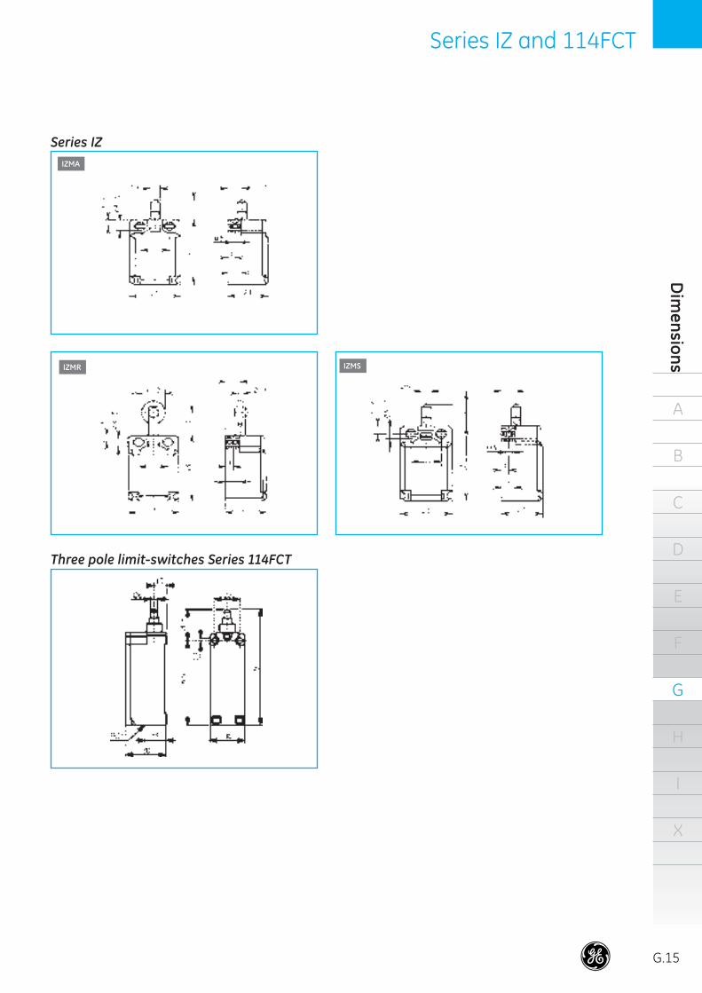
IZMA
IZMS
Series IZ
Three pole limit-switches Series 114FCT
IZMR
39584_G10_G15_E.indd 15 18-09-2007 12:09:38
A
G.16
B
C
D
E
F
G
H
I
X
Lim
it sw
itch
esSeries 115
Standards
IEC/EN 60947-5-1 BSICEI UTEVDE 0660
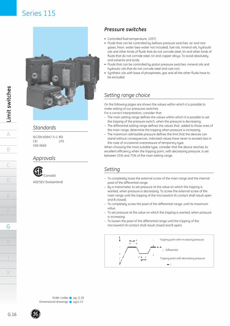
Pressure switches
• Controlled fl uid temperature: 120°C• Fluids that can be controlled by bellows pressure switches: air and rare
gases, freon, water (sea-water not included), fuel oils, mineral oils, hydraulic oils and other kinds of fl uids that do not corrode steel, tin and other kinds of fl uids that do not corrode steel, tin and copper alloys. To avoid absolutely and solvents and acids.
• Fluids that can be controlled by piston pressure switches: mineral oils and hydraulic oils that do not corrode steel and cast iron.
• Synthetic oils with base of phosphates, gas and all the other fl uids have to be excluded.
Setting range choice
On the following pages are shown the values within which it is possible to make setting of our pressures switches.For a correct interpretation, consider that:– The main setting range defi nes the values within which it is possible to set
the tripping of the pressure switch, when the pressure is decreasing.– The differential setting range defi nes the values that, added to those ones of
the main range, determine the tripping when pressure is increasing.– The maximum admissible pressure defi nes the limit that the devices can
stand without consequences. Indicated values have never to exceed also in the case of occasional overpressure of temporary type.
When choosing the most suitable type, consider that the device reaches its excellent effi ciency when the tripping point, with decreasing pressure, is set between 25% and 75% of the main setting range.
Setting
– To completely loose the external screw of the main range and the internal pawl of the differential range.
– By a manometer, to set pressure at the value on which the tripping is wanted, when pressure is decreasing. To screw the external screw of the main range until the tripping of the microswitch (A contact shall result open and B closed).
– To completely screw the pawl of the differential range, until its maximum value.
– To set pressure at the value on which the tripping is wanted, when pressure is increasing.
– To loosen the pawl of the differential range until the tripping of the microswitch (A contact shall result closed and B open).
Tripping point with decreasing pressure
Differential
Tripping point with increasing pressure
Approvals
(Canada)
ASE/SEV (Switzerland)
Order codesDimensional drawings
pg. G.18pg.G.15
!!
39584_G16_G21_E.indd 16 18-09-2007 12:10:04
Series 115
A
B
C
D
E
F
G
H
I
X
Pressure switches
G.17
Location
Generally the location of our pressure switches can be effected as wanted.Nevertheless, as to the piston types whitout seal ring, location have to be made in such a way as to allow the discharge, through the drainage hole, of the blow-by oil between cylinder and piston (a few drops per hour).The going-out oil can be collected by a proper drainage pipe that conveys it , free falling, into the tank of the hydraulic central, as shown in the below fi gure.
Caution
– Do not connect the drainage hole to a return pipe of the line...
– The drainage pipe must not cover a way different from that one indicated (e.g. towards the top).
– Do not plug the drainage holes.
If the above cautions are not met, inside the sensitive group there will be a counter pressure that could damage the sealing washer between actuator and frame of the pressure switch.
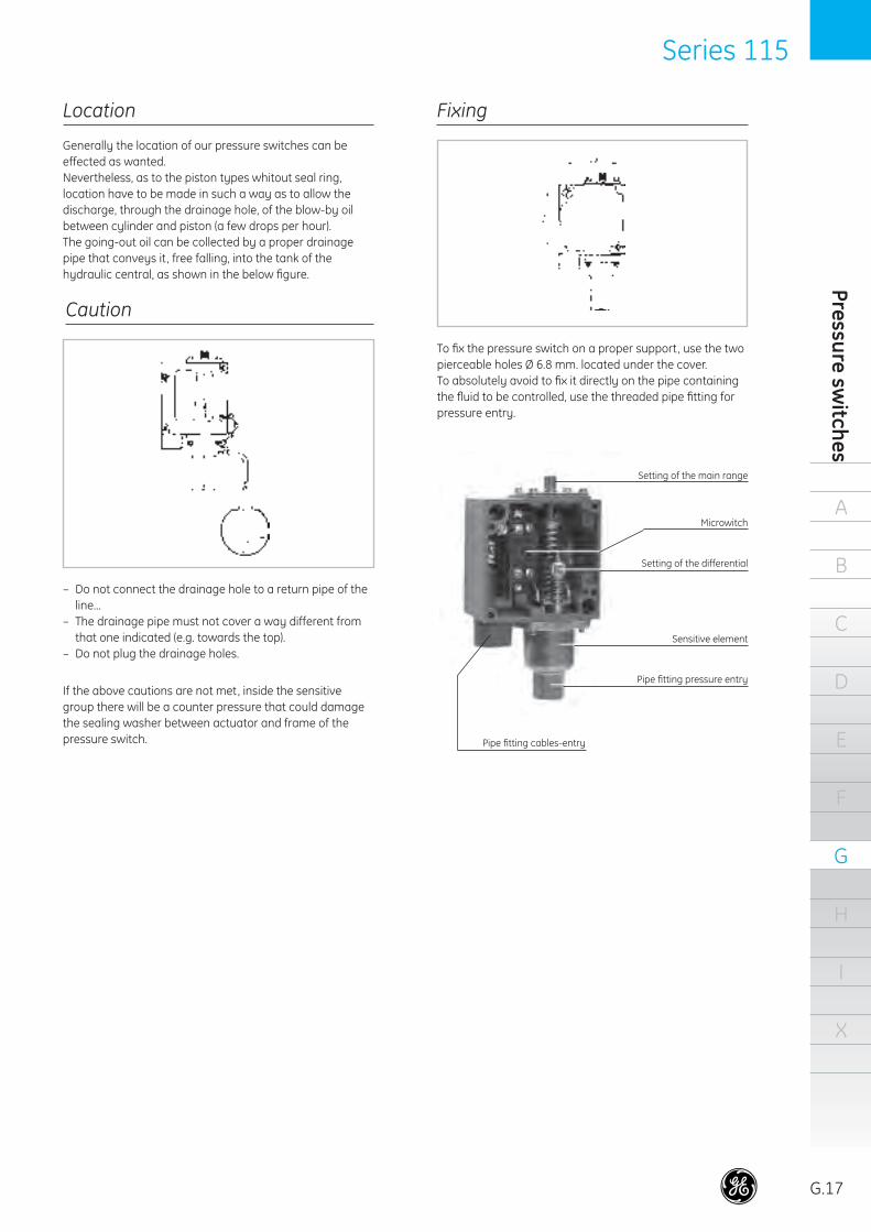
Fixing
To fi x the pressure switch on a proper support, use the two pierceable holes Ø 6.8 mm. located under the cover.To absolutely avoid to fi x it directly on the pipe containing the fl uid to be controlled, use the threaded pipe fi tting for pressure entry.
Setting of the main range
Pipe fi tting cables-entry
Pipe fi tting pressure entry
Sensitive element
Setting of the differential
Microwitch
39584_G16_G21_E.indd 17 18-09-2007 12:10:07
A
G.18
B
C
D
E
F
G
H
I
X
Lim
it sw
itch
esSeries 115
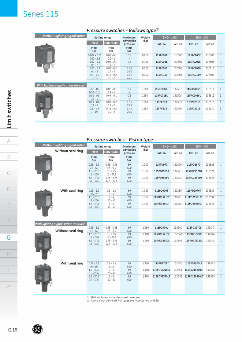
Pressure switches - Bellows type(1)
Without lighting signalisation
0.002 - 0.15 0.02 - 0.1 0.4 0.950 115PC002 132500 115PC2002 132504 1 0.02 - 1.5 0.2 - 1 4 0.01 - 0.5 0.04 - 0.1 0.6 0.950 115PC015 132501 115PC2015 132505 1 0.1 - 5 0.4 - 1 6 0.01 - 0.8 0.07 - 0.2 1.55 0.950 115PC018 132502 115PC2018 132515 1 0.1 - 8 0.7 - 2 15.5 0.1 - 1.9 0.12 - 0.2 2.45 0.950 115PC119 132503 115PC2119 132506 1 1 - 19 1.2 - 2 24.5
Setting range Maximum Weight Pack. admissible (kg) pressure Cat. no Ref. no Cat. no Ref. no Main Differential
2NO - 2NC
Mpa Mpa Mpa Bar Bar Bar
With lighting signalisation (red lens)(2) 0.002 - 0.15 0.02 - 0.1 0.4 0.950 115PC002L 132507 115PC2002L 132511 1 0.02 - 1.5 0.2 - 1 4 0.01 - 0.5 0.04 - 0.1 0.6 0.950 115PC015L 132508 115PC2015L 132512 1 0.1 - 5 0.4 - 1 6 0.01 - 0.8 0.07 - 0.2 1.55 0.950 115PC018 132509 115PC2018 132513 1 0.1 - 8 0.7 - 2 15.5 0.1 - 1.9 0.12 - 0.2 2.45 0.950 115PC119 132510 115PC2119 132514 1 1 - 19 1.2 - 2 24.5
(1) Bellows types in stainless steel on request.(2) Lamp is not delivered. For types see Accessories on G.19.
Pressure switches - Piston typeWithout lighting signalisation
0,95 - 6,9 0,35 - 0,95 69 1,360 115PD970 132520 115PD2970 132523 1 9,5 - 69 3,5 - 9,5 690 1,5 - 20,6 1 - 2,75 69 1,360 115PD15210 132521 115PD215210 132524 1 15 - 206 10 - 27,5 690 3,7 - 34,5 1,75 - 2,75 69 1,360 115PD38350 132522 115PD238350 132525 1 37 - 345 17,5 - 27,5 690
0.95 - 6.9 0.6 - 1.4 69 1.360 115PD970T 132530 115PD2970T 132533 1 9.5-69 6-14 690 1.5 - 20.6 2 - 4 69 1.360 115PD15210T 132531 115PD215210T 132534 1 15 - 206 20 - 40 690 3.7 - 34.5 3 - 5 69 1.360 115PD38350T 132532 115PD238350T 132535 1 37 - 345 30 - 50 690
Without seal ring
With seal ring
0.95 - 6.9 0.35 - 0.95 69 1.360 115PD970L 132540 115PD2970L 132543 1 9.5 - 69 3.5 - 9.5 690 1.5 - 20.6 1 - 2.75 69 1.360 115PD15210L 132541 115PD215210L 132544 1 15 - 206 10 - 27.5 690 3.7 - 34.5 1.75 - 2.75 69 1.360 115PD38350L 132542 115PD238350L 132545 1 37 - 345 17.5 - 27.5 690
0.95 - 6.9 0.6 - 1.4 69 1.360 115PD970LT 132550 115PD2970LT 132553 1 9.5-69 6-14 690 1.5 - 20.6 2 - 4 69 1.360 115PD15210LT 132551 115PD215210LT 132554 1 15 - 206 20 - 40 690 3.7 - 34.5 3 - 5 69 1.360 115PD38350LT 132552 115PD238350LT 132555 1 37 - 345 30 - 50 690
Without seal ring
With seal ring
With lighting signalisation (red lens)(2)
1NO - 1NC
Setting range Maximum Weight Pack. admissible (kg) pressure Cat. no Ref. no Cat. no Ref. no Main Differential
2NO - 2NC
Mpa Mpa Mpa Bar Bar Bar
1NO - 1NC
39584_G16_G21_E.indd 18 18-09-2007 12:10:07
Series 115
A
B
C
D
E
F
G
H
I
X
Pressure switches
G.19
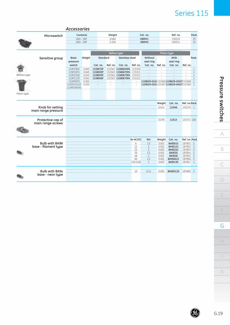
AccessoriesMicroswitch
1NO - 1NF 0.060 090MI1 130310 25 2NO - 2NF 0.100 090MI2 130311 25
Sensitive group Piston type
115PC002 0.045 115807SP 132562 1158065SPA 215320 - - - - 1 115PC015 0.045 115803SP 132563 1158067SPA 215321 - - - - 1 115PC018 0.045 115805SP 132564 1158067SPA 215321 - - - - 1 115PC119 0.045 115804SP 132565 1158067SPA 215321 - - - - 1 115PD970 0.505 - - - - 1158029-01GI 132566 1158029-03GIT 132568 1 115PD15210 0.505 - - - - 1158029-02GI 132567 1158029-04GIT 132569 1 115PD38350
Basic Weight Standard Without With Pack. pressure seal ring seal ring switch Cat. no. Ref. no. Cat. no. Ref. no. Cat. no. Ref. no. Cat. no. Ref. no.
Knob for setting main range pressure
Bellows type
Piston type
Protective cap of main range screws
Bulb with BA96 base - fi lament type
Bulb with BA9s base - neon type
Contacts Weight Cat. no. Ref. no. Pack.
Weight Cat. no. Ref. no. Pack.
Bellow type
Stainless steel
0.014 115MA 132570 1
0.078 115CA 132571 100
Vn AC/DC Wn Weight Cat. no. Ref. no. Pack 6 1.5 0,002 BA9S615 187851 5 12 2 0,002 BA9S122 187852 5 24 2 0,002 BA9S242 187853 5 30 2.1 0,002 BA9S30 187854 5 48 2 0,002 BA9S48 187855 5 60 1.2 0,002 BA9S6012 187856 5 130 (110) 2 0,002 BA9S130 187857 5
10 0.11 0,002 BA9SN110 187860 5
39584_G16_G21_E.indd 19 18-09-2007 12:10:08
A
G.20
B
C
D
E
F
G
H
I
X
Lim
it sw
itch
esSeries 115
The pressure switches Series 115 are designed for trans-forming a pressure variation into an electrical signal when a pre-arranged pressure value is reached.Pressure switches are utilized in the fi eld of the industry machines, installations and transports.
Climatic protections
Insulation classIP65 IEC/EN 60529ENCL. 4, 5 CSA
General
Temperature climate cat. 23/50 (DIN 50014)Wet climate cat. 23/83 (DIN 50015)Hot wet climate cat. 40/92 (DIN 50015)Variable wet climate cat. FW24 (DIN 50016)
Electrical performances
Technical data
Temperature rangesOperation –25°C to +70° CStorage –40°C to +70°C
Vibration resistance5g at a sinusoidal frequency ranging IEC 68-2-6from to 100 Hz according to IEC 68-2-6
090MI1 (1NO + 1NC)090MI2 (2NO + 2NC)Rated thermal current: Ith = 10 A
Performances according IEC 947.5.1
AC/Heavy Duty (A/600)DC/Standard Duty (Q300)Connections at same polarity
Connection terminalsScrew type without clamping screw.Suitable for eye, fork and hook terminals.
Cable entryOne PG 13.5 threaded cable entry.
RangeThe pressure switches series 115 are available in two basic versions:– With bellows sensitive element for pressures ranging
between 0.002 Mpa (0.02 bar) minimum and 2.1 Mpa (21 bar) maximum.– With piston sensitive element for pressures ranging
between 0.95 Mpa (9.5 bar) minimum and 37.25 Mpa (372.5 bar) maximum.Both versions can be supplied:• Without lighting signaling• With lighting signaling
ConstructionSnap-action 1NO-1NC or 2NO+2NC microswitches with double-break contacts without positive-break of the NC contact.Bellows sensitive element, hermetic sealing, made by Tombacco (or stainless steel) material enclosed into a die-cast zamac case complete with a 1 mm. damper.Piston sensitive element, with or without seal ring, with steel piston enclosed into a cast-iron cylinder complete with 1 mm. damper.Enclosure and cover are made of die-cast aluminium and painted with anaphoresis process grey RAL 7012..
Rated insulation voltage
Mechanical endurance
Bellows type1 million operations. It can be considerably reduced when the pressure jump reachs the maximum value foreseen for every type of device and the operations number is high.The bellows endurance can be also negatively infl uenced by the temperature and the kind of controlled fl uid.
3 million operations
Piston type
600V AC/DC
Insulation classGroup C according to VDE 0110
Short-circuit protection10 A gL fuses according to IEC 947-5-1
Category AC15 (A600)Voltage Ue V 24 48 60 110 220 380 500 600Current Ie A 10 10 10 6 3 2 1,5 1,2Category DC 13 (P600)Voltage Ue V 24 48 60 110 220 300Current Ie A 2.5 1.4 1 0.55 0.27 0.2
Performances according to CSA
39584_G16_G21_E.indd 20 18-09-2007 12:10:09
Series 115
A
B
C
D
E
F
G
H
I
X
Pressure switches
G.21
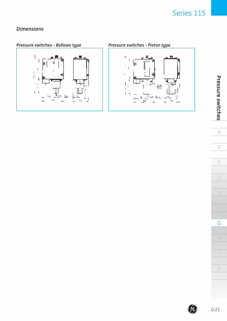
Dimensions
Pressure switches - Bellows type Pressure switches - Piston type
39584_G16_G21_E.indd 21 18-09-2007 12:10:10