Embed Size (px)
Citation preview
Series TDType TDLType TDMAutomatic Recirculation Valve for pump protection
2
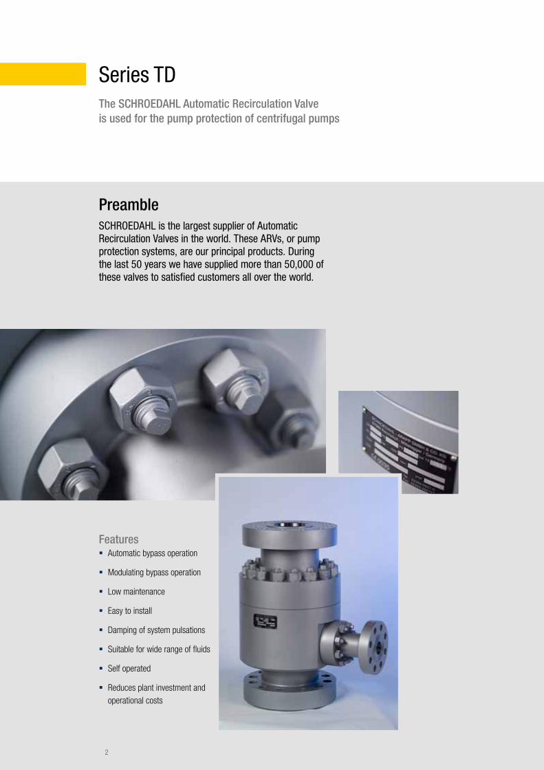
Series TDThe SCHROEDAHL Automatic Recirculation Valve is used for the pump protection of centrifugal pumps
Features � Automatic bypass operation
� Modulating bypass operation
� Low maintenance
� Easy to install
� Damping of system pulsations
� Suitable for wide range of fluids
� Self operated
� Reduces plant investment and operational costs
PreambleSCHROEDAHL is the largest supplier of Automatic Recirculation Valves in the world. These ARVs, or pump protection systems, are our principal products. During the last 50 years we have supplied more than 50,000 of these valves to satisfied customers all over the world.
3
ApplicationThe SCHROEDAHL Automatic Recirculation Valve is a high quality automatic solution to protect centrifugal pumps against overheating, instability and cavitation, during zero process flow and low load conditions.
If the flow through the system is or falls below a certain level, the bypass system opens automatically and the fluid is recirculated, providing the required minimum flow for the pump.
Special operation requirements, low load cases, complicated commissioning situations and the pressure in the bypass line have an impact on the valve design and therefore are typically part of customers RFQ information - SCHROEDAHL can offer solutions at a very high level.
The SCHROEDAHL automatic recirculation valve is therefore a high quality, cheaper and easier solution for clean liquid pump protection - more cost effective than a conventional modulating control valve package.
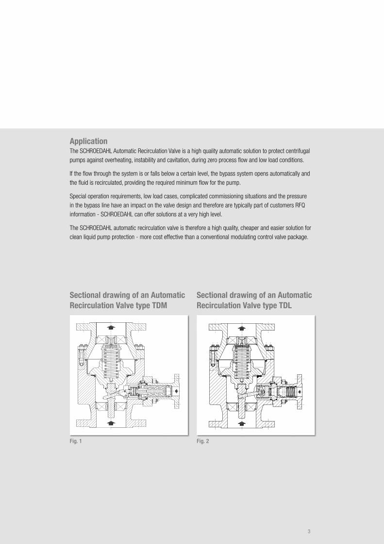
Sectional drawing of an Automatic Recirculation Valve type TDM
Sectional drawing of an Automatic Recirculation Valve type TDL
Fig. 1 Fig. 2
4
Operation of the Automatic Recirculation Valves
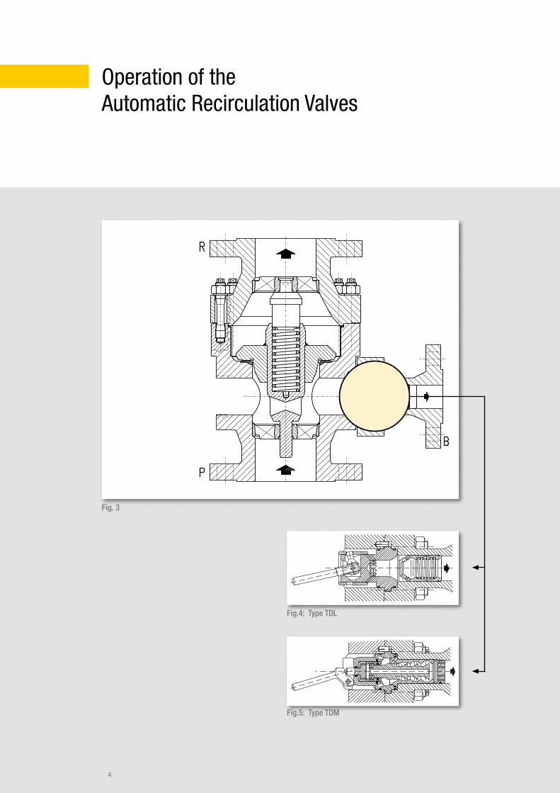
Fig. 3
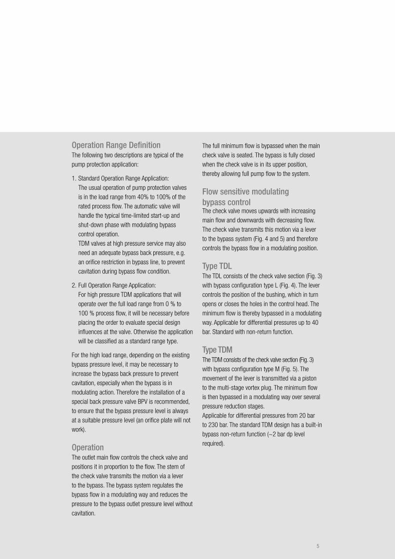
Fig.4: Type TDL
Fig.5: Type TDM
5
Operation Range DefinitionThe following two descriptions are typical of the pump protection application:
1. Standard Operation Range Application: The usual operation of pump protection valves is in the load range from 40% to 100% of the rated process flow. The automatic valve will handle the typical time-limited start-up and shut-down phase with modulating bypass control operation. TDM valves at high pressure service may also need an adequate bypass back pressure, e.g. an orifice restriction in bypass line, to prevent cavitation during bypass flow condition.
2. Full Operation Range Application: For high pressure TDM applications that will operate over the full load range from 0 % to 100 % process flow, it will be necessary before placing the order to evaluate special design influences at the valve. Otherwise the application will be classified as a standard range type.
For the high load range, depending on the existing bypass pressure level, it may be necessary to increase the bypass back pressure to prevent cavitation, especially when the bypass is in modulating action. Therefore the installation of a special back pressure valve BPV is recommended, to ensure that the bypass pressure level is always at a suitable pressure level (an orifice plate will not work).
OperationThe outlet main flow controls the check valve and positions it in proportion to the flow. The stem of the check valve transmits the motion via a lever to the bypass. The bypass system regulates the bypass flow in a modulating way and reduces the pressure to the bypass outlet pressure level without cavitation.
The full minimum flow is bypassed when the main check valve is seated. The bypass is fully closed when the check valve is in its upper position, thereby allowing full pump flow to the system.
Flow sensitive modulating bypass controlThe check valve moves upwards with increasing main flow and downwards with decreasing flow. The check valve transmits this motion via a lever to the bypass system (Fig. 4 and 5) and therefore controls the bypass flow in a modulating position.
Type TDLThe TDL consists of the check valve section (Fig. 3) with bypass configuration type L (Fig. 4). The lever controls the position of the bushing, which in turn opens or closes the holes in the control head. The minimum flow is thereby bypassed in a modulating way. Applicable for differential pressures up to 40 bar. Standard with non-return function.
Type TDM The TDM consists of the check valve section (Fig. 3) with bypass configuration type M (Fig. 5). The movement of the lever is transmitted via a piston to the multi-stage vortex plug. The minimum flow is then bypassed in a modulating way over several pressure reduction stages. Applicable for differential pressures from 20 bar to 230 bar. The standard TDM design has a built-in bypass non-return function (~2 bar dp level required).
6
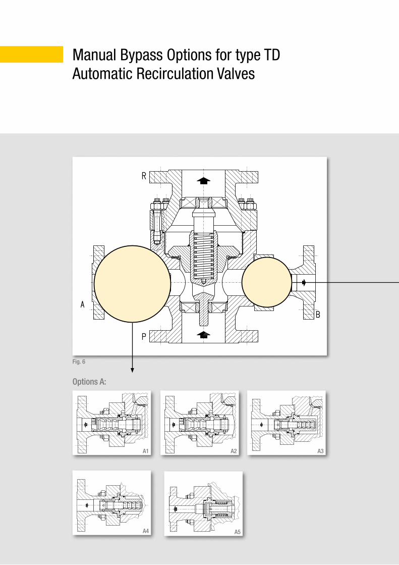
Manual Bypass Options for type TD Automatic Recirculation Valves
A2
A5
A3A1
A4
Options A:
Fig. 6
7
B-TDM
B-TDL
Options A:Additional connection options (on request):
A1: Start-up/warm-up above check valve
A2: Start-up/warm-up below check valve.
A3: Warm-up above check valve.
A4: Warm-up below check valve.
A5: Degassing Nozzle
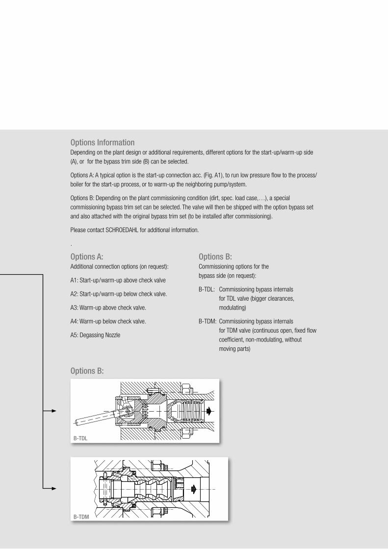
Options B:Commissioning options for the bypass side (on request):
B-TDL: Commissioning bypass internals for TDL valve (bigger clearances, modulating)
B-TDM: Commissioning bypass internals for TDM valve (continuous open, fixed flow coefficient, non-modulating, without moving parts)
Options InformationDepending on the plant design or additional requirements, different options for the start-up/warm-up side (A), or for the bypass trim side (B) can be selected.
Options A: A typical option is the start-up connection acc. (Fig. A1), to run low pressure flow to the process/boiler for the start-up process, or to warm-up the neighboring pump/system.
Options B: Depending on the plant commissioning condition (dirt, spec. load case,…), a special commissioning bypass trim set can be selected. The valve will then be shipped with the option bypass set and also attached with the original bypass trim set (to be installed after commissioning).
Please contact SCHROEDAHL for additional information.
.
Options B:
8
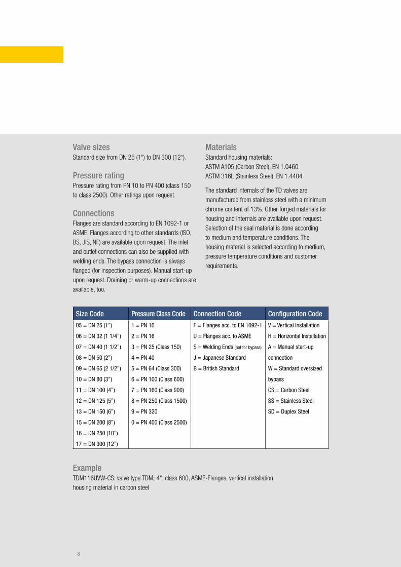
Size Code Pressure Class Code Connection Code Configuration Code
05 = DN 25 (1”)
06 = DN 32 (1 1/4”)
07 = DN 40 (1 1/2”)
08 = DN 50 (2”)
09 = DN 65 (2 1/2”)
10 = DN 80 (3”)
11 = DN 100 (4”)
12 = DN 125 (5”)
13 = DN 150 (6”)
15 = DN 200 (8”)
16 = DN 250 (10”)
17 = DN 300 (12”)
1 = PN 10
2 = PN 16
3 = PN 25 (Class 150)
4 = PN 40
5 = PN 64 (Class 300)
6 = PN 100 (Class 600)
7 = PN 160 (Class 900)
8 = PN 250 (Class 1500)
9 = PN 320
0 = PN 400 (Class 2500)
F = Flanges acc. to EN 1092-1
U = Flanges acc. to ASME
S = Welding Ends (not for bypass)
J = Japanese Standard
B = British Standard
V = Vertical Installation
H = Horizontal Installation
A = Manual start-up
connection
W = Standard oversized
bypass
CS = Carbon Steel
SS = Stainless Steel
SD = Duplex Steel
ExampleTDM116UVW-CS: valve type TDM; 4“, class 600, ASME-Flanges, vertical installation, housing material in carbon steel
Valve sizesStandard size from DN 25 (1“) to DN 300 (12“).
Pressure ratingPressure rating from PN 10 to PN 400 (class 150 to class 2500). Other ratings upon request.
ConnectionsFlanges are standard according to EN 1092-1 or ASME. Flanges according to other standards (ISO, BS, JIS, NF) are available upon request. The inlet and outlet connections can also be supplied with welding ends. The bypass connection is always flanged (for inspection purposes). Manual start-up upon request. Draining or warm-up connections are available, too.
MaterialsStandard housing materials: ASTM A105 (Carbon Steel), EN 1.0460 ASTM 316L (Stainless Steel), EN 1.4404
The standard internals of the TD valves are manufactured from stainless steel with a minimum chrome content of 13%. Other forged materials for housing and internals are available upon request. Selection of the seal material is done according to medium and temperature conditions. The housing material is selected according to medium, pressure temperature conditions and customer requirements.
9
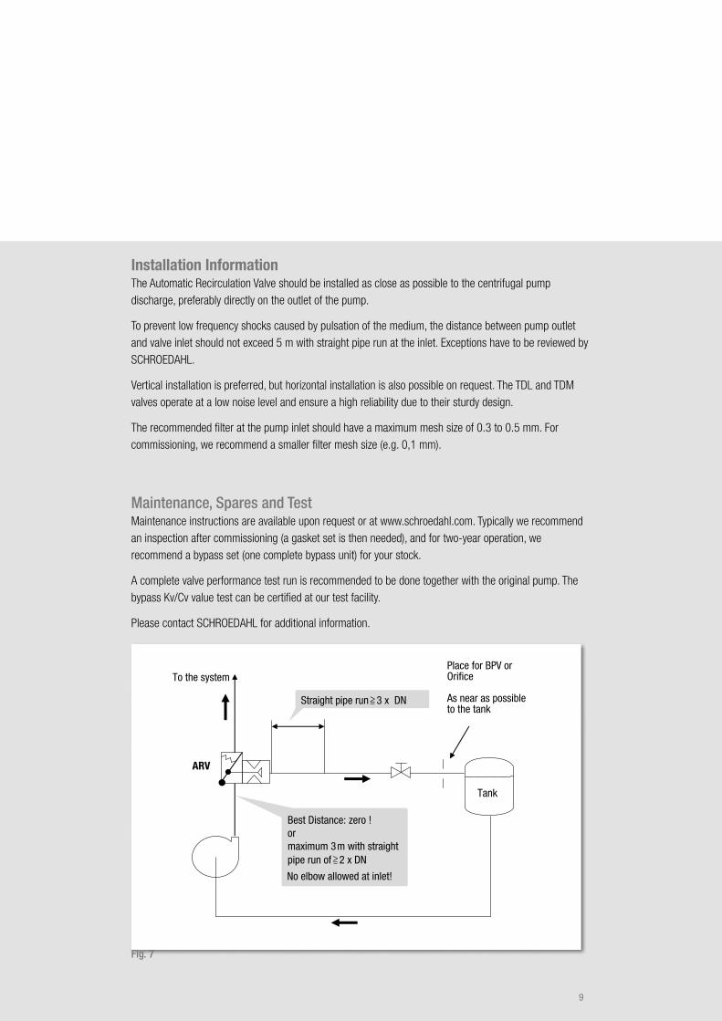
To the system
ARV
Place for BPV orOrifice
As near as possibleto the tank
Tank
Straight pipe run 3 x DN
Best Distance: zero !ormaximum 3m with straightpipe run of 2 x DN
No elbow allowed at inlet!
Installation InformationThe Automatic Recirculation Valve should be installed as close as possible to the centrifugal pump discharge, preferably directly on the outlet of the pump.
To prevent low frequency shocks caused by pulsation of the medium, the distance between pump outlet and valve inlet should not exceed 5 m with straight pipe run at the inlet. Exceptions have to be reviewed by SCHROEDAHL.
Vertical installation is preferred, but horizontal installation is also possible on request. The TDL and TDM valves operate at a low noise level and ensure a high reliability due to their sturdy design.
The recommended filter at the pump inlet should have a maximum mesh size of 0.3 to 0.5 mm. For commissioning, we recommend a smaller filter mesh size (e.g. 0,1 mm).
Maintenance, Spares and TestMaintenance instructions are available upon request or at www.schroedahl.com. Typically we recommend an inspection after commissioning (a gasket set is then needed), and for two-year operation, we recommend a bypass set (one complete bypass unit) for your stock.
A complete valve performance test run is recommended to be done together with the original pump. The bypass Kv/Cv value test can be certified at our test facility.
Please contact SCHROEDAHL for additional information.
Fig. 7
10
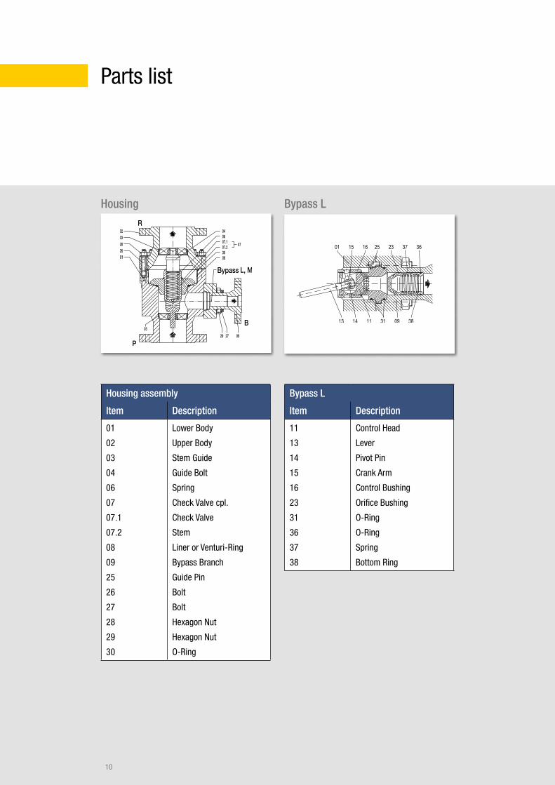
Parts list
Housing Bypass L
Housing assembly
Item Description
01
02
03
04
06
07
07.1
07.2
08
09
25
26
27
28
29
30
Lower Body
Upper Body
Stem Guide
Guide Bolt
Spring
Check Valve cpl.
Check Valve
Stem
Liner or Venturi-Ring
Bypass Branch
Guide Pin
Bolt
Bolt
Hexagon Nut
Hexagon Nut
O-Ring
Bypass L
Item Description
11
13
14
15
16
23
31
36
37
38
Control Head
Lever
Pivot Pin
Crank Arm
Control Bushing
Orifice Bushing
O-Ring
O-Ring
Spring
Bottom Ring
Bypass
11
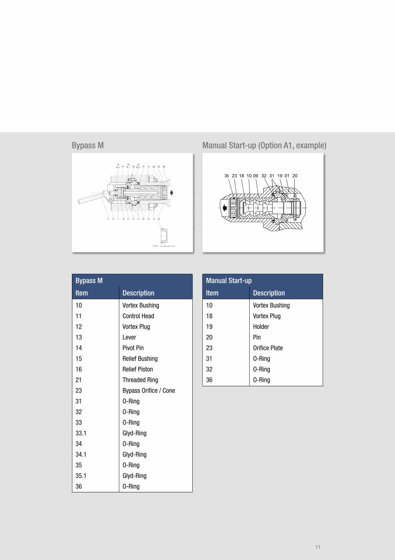
Bypass M Manual Start-up (Option A1, example)
Bypass M
Item Description
10
11
12
13
14
15
16
21
23
31
32
33
33.1
34
34.1
35
35.1
36
Vortex Bushing
Control Head
Vortex Plug
Lever
Pivot Pin
Relief Bushing
Relief Piston
Threaded Ring
Bypass Orifice / Cone
O-Ring
O-Ring
O-Ring
Glyd-Ring
O-Ring
Glyd-Ring
O-Ring
Glyd-Ring
O-Ring
Manual Start-up
Item Description
10
18
19
20
23
31
32
36
Vortex Bushing
Vortex Plug
Holder
Pin
Orifice Plate
O-Ring
O-Ring
O-Ring
12
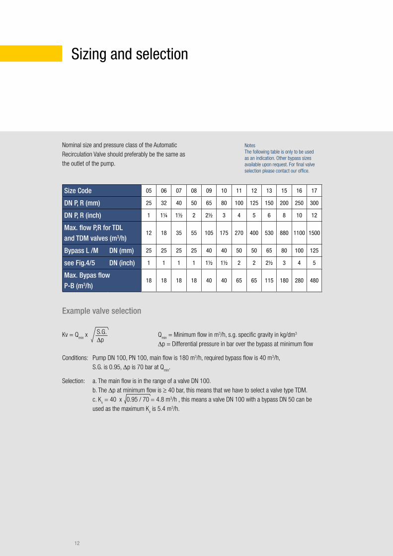
Nominal size and pressure class of the Automatic Recirculation Valve should preferably be the same as the outlet of the pump.
Size Code 05 06 07 08 09 10 11 12 13 15 16 17
DN P, R (mm) 25 32 40 50 65 80 100 125 150 200 250 300
DN P, R (inch) 1 1¼ 1½ 2 2½ 3 4 5 6 8 10 12
Max. flow P,R for TDL and TDM valves (m3/h)
12 18 35 55 105 175 270 400 530 880 1100 1500
Bypass L /M DN (mm) 25 25 25 25 40 40 50 50 65 80 100 125
see Fig.4/5 DN (inch) 1 1 1 1 1½ 1½ 2 2 2½ 3 4 5
Max. Bypas flow P-B (m3/h)
18 18 18 18 40 40 65 65 115 180 280 480
Notes The following table is only to be used as an indication. Other bypass sizes available upon request. For final valve selection please contact our office.
Example valve selection
Kv = Qmin
x
Conditions: Pump DN 100, PN 100, main flow is 180 m3/h, required bypass flow is 40 m3/h, S.G. is 0.95, Δp is 70 bar at Q
min.
Selection: a. The main flow is in the range of a valve DN 100. b. The Δp at minimum flow is ≥ 40 bar, this means that we have to select a valve type TDM. c. K
v = 40 x 0.95 / 70 = 4.8 m3/h , this means a valve DN 100 with a bypass DN 50 can be
used as the maximum Kv is 5.4 m3/h.
Qmin
= Minimum flow in m3/h, s.g. specific gravity in kg/dm3 Δp = Differential pressure in bar over the bypass at minimum flow
Sizing and selection
S.G. Δp
13
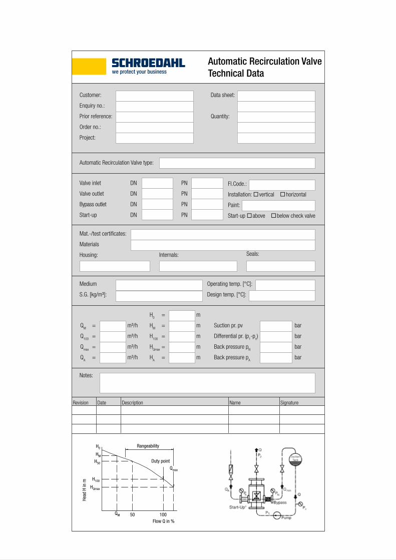
Customer:
Enquiry no.:
Prior reference:
Order no.:
Project:
Automatic Recirculation Valve Technical Data
Data sheet:
Quantity:
Automatic Recirculation Valve type:
Mat.-/test certificates:
Materials
Housing: Internals: Seals:
Medium
S.G. [kg/m³]:
Operating temp. [°C]:
Design temp. [°C]:
QM = m³/h
Q100
= m³/h
Qmax
= m³/h
QA = m³/h
H0 = m
HM = m
H100
= m
HQmax
= m
HA = m
Suction pr. pv bar
Differential pr. (p1-p
n) bar
Back pressure pN bar
Back pressure pA bar
Notes:
Fl.Code.:
Installation: vertical horizontal
Paint:
Start-up above below check valve
Revision Date Description Name Signature
Valve inlet DN PN
Valve outlet DN PN
Bypass outlet DN PN
Start-up DN PN
P1
Pv
PN
Qmin
Q
P2
Q
pump
tank
bypass-branch
Duty point
Rangeability
Flow Q in %
H0
HM
H50
H100
Qmax
QM 50 100
HQmax
Head
H in
m
14
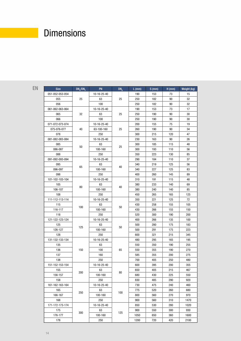
Dimensions
EN Size DNR/DNP PN DNB L (mm) S (mm) H (mm) Weight (kg)
051-052-053-054
25
10-16-25-40
25
190 153 73 15
055 63 250 182 90 32
056 100 250 182 90 32
061-062-063-064
32
10-16-25-40
25
190 153 73 17
065 63 250 190 90 30
066 100 250 190 90 30
071-072-073-074
40
10-16-25-40
25
200 155 75 19
075-076-077 63-100-160 260 190 90 34
078 250 300 215 120 47
081-082-083-084
50
10-16-25-40
25
230 163 90 26
085 63 300 185 115 48
086-087 100-160 300 193 110 56
088 250 350 223 130 85
091-092-093-094
65
10-16-25-40
40
290 184 110 37
095 63 340 219 125 56
096-097 100-160 340 227 125 83
098 250 400 260 145 89
101-102-103-104
80
10-16-25-40
40
310 191 115 48
105 63 380 233 140 69
106-107 100-160 380 240 140 85
108 250 450 265 165 125
111-112-113-114
100
10-16-25-40
50
350 221 125 72
115 63 430 258 155 105
116-117 100-160 430 266 155 150
118 250 520 300 190 200
121-122-123-124
125
10-16-25-40
50
400 266 135 100
125 63 500 280 175 183
126-127 100-160 500 291 175 223
128 250 600 321 215 345
131-132-133-134
150
10-16-25-40
65
480 295 165 195
135 63 550 350 190 255
136 100 550 355 190 270
137 160 585 355 200 275
138 250 700 405 250 480
151-152-153-154
200
10-16-25-40
80
600 395 200 355
155 63 650 405 215 467
156-157 100-160 680 430 225 550
158 250 830 485 290 920
161-162-163-164
250
10-16-25-40
100
730 475 240 460
165 63 775 520 260 680
166-167 100-160 800 560 270 970
168 250 900 560 310 1470
171-172-173-174
300
10-16-25-40
125
850 530 280 1020
175 63 900 550 300 930
176-177 100-160 1050 650 360 1600
178 250 1200 720 420 2100
15
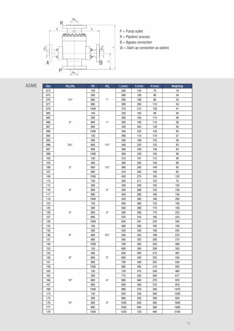
P = Pump outlet R = Pipeline/ process B = Bypass connection (A = Start-up connection as option)
ASME Size DNR/DNP PN DNB L (mm) S (mm) H (mm) Weight (kg)
073
1½"
150
1"
200 155 75 19
075 300 260 190 90 34
076 600 260 190 90 34
077 900 300 200 110 34
078 1500 310 215 120 47
083
2"
150
1"
230 163 90 26
085 300 300 185 115 48
086 600 300 193 110 56
087 900 340 203 130 56
088 1500 350 233 130 85
093
2½"
150
1½"
290 174 110 37
095 300 340 199 125 56
096 600 340 220 125 83
097 900 380 230 140 83
098 1500 400 250 145 89
103
3"
150
1½"
310 191 115 48
105 300 380 220 140 69
106 600 380 240 140 85
107 900 410 250 150 85
108 1500 450 275 165 125
113
4"
150
2"
350 211 125 72
115 300 430 240 155 105
116 600 430 266 155 150
117 900 450 280 160 150
118 1500 520 300 190 200
123
5"
150
2"
400 266 135 100
125 300 500 290 175 183
126 600 500 300 175 223
127 900 525 310 185 223
128 1500 650 341 235 345
133
6"
150
2½"
480 295 165 195
135 300 550 350 190 255
136 600 550 355 190 270
137 900 585 355 200 275
138 1500 700 405 250 480
153
8"
150
3"
600 395 200 355
155 300 650 405 215 467
156 600 680 430 225 550
157 900 700 430 225 550
158 1500 880 485 310 920
163
10"
150
4"
730 475 240 460
165 300 775 520 260 677
166 600 800 560 270 970
167 900 800 560 270 970
168 1500 980 570 340 1470
173
12"
150
5"
850 530 280 1020
175 300 900 550 300 930
176 600 1050 650 360 1600
177 900 1050 650 360 1600
178 1500 1250 720 440 2100
©20
16 X
YQOM
Gm
bH · w
ww.xy
qom
.net /
rev.
2016
_UK_
005
SCHROEDAHL GmbH Alte Schönenbacher Str. 4 51580 Reichshof-Mittelagger GERMANY
Phone +49 2265 9927-0 Fax +49 2265 9927-927
www.schroedahl.com [email protected]