Embed Size (px)
Citation preview
Series Touch Panel
(Dimming) (Dimming) (CT)
Q seriesremote
F seriesremote
APP
2
12-24Vdc
RGB RGBW
4A×3CH Max. 12A 3A×4CH Max. 12A
-20℃~55℃
L86×W86×H36(mm)
L113×W112×H50(mm)
225g
(0~48W...96W)×3CH Max. 288W
(0~36W...72W)×4CH Max. 288W
RF 2.4GHz
warranty5 years
E3(RGB)
E3S(RGB)
3
E1
E1/ / / /E1S E2 E3 E3S
E4 E4S/
E1S E2
4A×2CH Max. 8A
(0~48W...96W)×2CH Max. 192W
E1 E3 E4E1S E3S E4SE2
Max. 4A
0~48...96W
E4(RGBW)
E4S(RGBW)
4 5 6 7
E4
E4S
55
55
60
60
25
48 8282
8686
86
86
48
48
22
48
Ma ualnwww.ltech-led.com
Product Features●
●
●
●
● Touch keys with chord and LED indicator.
2 in 1 function: RF wireless control and PWM power output.
Power output, lamps can be connected directly, easy and convenient.
Touch panel can be controlled by remote directly or smart phone if add a gateway.
Adopts capacitive touch control technology on the full color circle makes LED dimming selection more user-friendly.
Technical Specs
Weight(G.W.)
Control Type
Model
Input Voltage
Wireless Frequency
Current Load
Output Power
Protection
Working Temp.
Dimensions
Package Size
Dimming CT
Short circuit / Over current protection, auto recovers.Reverse connection protection.
Reverse connection protection.
Installation Instruction
Touch panel
BaseplateBase
Typical base as below:
European style 86 size Uninstall
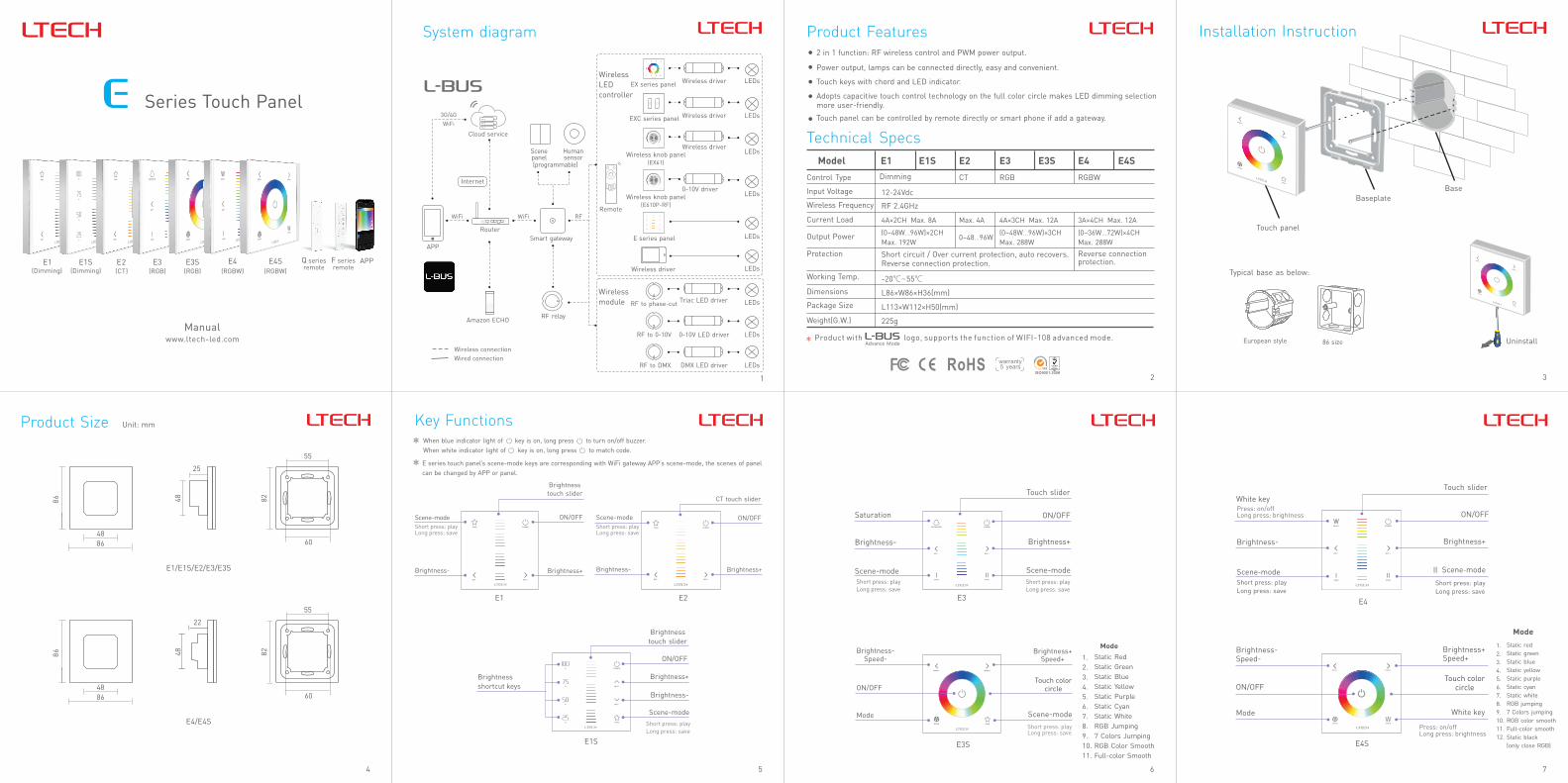
Product Size Unit: mm Key Functions
E1S
E1 E2 E3
E3S
Brightness-Speed-
Brightness+Speed+
Touch color circle
Short press: playLong press: save
Mode
ON/OFF
Static RedStatic GreenStatic BlueStatic YellowStatic PurpleStatic CyanStatic WhiteRGB Jumping7 Colors JumpingRGB Color SmoothFull-color Smooth
1. 2. 3. 4. 5. 6. 7. 8. 9. 10. 11.
Mode
Touch slider
ON/OFF
Brightness+
Scene-mode
Scene-mode
Short press: playLong press: save
Saturation
Brightness-
Scene-modeShort press: playLong press: save
Brightness
touch slider
ON/OFF
Brightness+
Brightness-
Brightness shortcut keys
Scene-modeShort press: playLong press: save
Short press: playLong press: save
Short press: playLong press: save
Brightness
touch slider
ON/OFF
Brightness+Brightness-
Scene-mode
CT touch slider
ON/OFF
Brightness+Brightness-
Scene-mode
E series touch panel’s scene-mode keys are corresponding with WiFi gateway APP’s scene-mode, the scenes of panel can be changed by APP or panel.
When blue indicator light of key is on, long press to turn on/off buzzer.When white indicator light of key is on, long press to match code.
Touch slider
ON/OFF
Brightness+
Scene-mode
Short press: playLong press: save
White keyPress: on/offLong press: brightness
Brightness-
Scene-modeShort press: playLong press: save
ON/OFF
Brightness-Speed-
Brightness+Speed+
Mode
Touch color circle
Static redStatic greenStatic blueStatic yellowStatic purpleStatic cyanStatic whiteRGB jumping7 Colors jumpingRGB color smoothFull-color smoothStatic black(only close RGB)
1. 2. 3. 4. 5. 6. 7. 8. 9. 10. 11. 12.
Mode
White key
Press: on/offLong press: brightness
Product with logo, supports the function of WIFI-108 advanced mode.
1
Internet
WiFi WiFi RF
WiFi
3G/4G
APP
Wireless driver
Wireless driver
EX series panel
EXC series panel
Wireless LEDcontroller
Remote
Cloud service
Smart gateway
Human sensor
Scene panel
RF relay
LEDs
LEDs
LEDs
LEDs
LEDs
LEDs
LEDs
Wireless driver
E series panel
Triac LED driver
0-10V LED driver
DMX LED driver RF to DMX
Wireless module
RF 0-10V to
RF to phase-cut
Wireless connectionWired connection
Router
Amazon ECHO
(programmable)
System diagram
Wireless knob panel(EX61)
Wireless knob panel(E610P-RF)
Wireless driver
0-10V driver
LEDs
LEDs

8 10
DC-
DC-
DC+
DC+
V+
R
W
G
W
B
E1/E1S
E3/E3S E4/E4S
E2
DC- DC+ V+ C W
E4/E4S
E4/E4S
9 11
12 13
V+
V+
V+
V+
V-
R G B W
V-
14 15
E3 E3E4 E4E3S E3SE4S E4SE1 E1E1S E1SE2 E2
F1 F5F2 F6F3 F7F4 F8(RGB)(Dimming) (CT) (CT)(Dimming) (RGB)(RGBW) (RGBW)
2.
511
511
331
+
B
R
G
+
B
R
G
511
511
331
511
511
331
+
B
R
G
+
B
R
G
511
511
331
511
511
331
+
B
R
G
+
B
R
G
511
511
331
511
511
331
+
B
R
G
+
B
R
G
511
511
331
511
511
331
+
B
R
G
+
B
R
G
511
511
331
220V/110Vac
220V/110Vac
24Vdc
24Vdc
DC24V
DC24V
DC24V
DC24V
DC24V
DC24V
DC24V
DC24V
DC24V
DC24V
DC24V
DC24V
DC24V
DC24V
DC24V
DC24V
DC24V
DC24V
DC24V
DC24V
DC24V
DC24V
DC24V
DC24V
DC24V
DC24V
DC24V
DC24V
DC24V
DC24V
DC24V
DC24V
R4 R5
R2
R4
R3
DC24V
DC24V
G
R
B
W
G
R
B
W
G
R
B
W
DC24V DC24V DC24VDC24V
RGB RGBRGB RGBW W WWW
R6
R1
R6R2 R4R3 R5
RGB
RGB
R1
R2
R4
R3
R5
RGB
DC24V
DC24V
DC24V
DC24V
DC24V
DC24V
DC24V
DC24V
DC24V
DC24V
DC24V
DC24V
DC24V
DC24V
DC24V
DC24V
DC24V
DC24V
DC24V
DC24V
DC24V
DC24V
DC24V
DC24V
DC24V
DC24V
DC24V
DC24V
DC24V
DC24V
DC24V
DC24V
R4 R5
R2
R4
R3
DC24V
DC24V
G
R
B
W
G
R
B
W
G
R
B
W
DC24V DC24V DC24VDC24V
RGB RGBRGB RGBW W WWW
R6
R1
R6R2 R4R3 R5
RGB
RGB
R1
R2
R4
R3
R5
RGB
Wiring Diagram
24Vdc
E1/E1S
E1/E1S
E3/E3S
E3/E3S
E2
E2
G
R
B
G
R
BG
R
B
G
R
B
G
R
BG
R
B
G
R
B
G
R
B
G
R
B
G
R
B
G
R
B
G
R
B
G
R
B
G
R
B
G
R
B
G
R
B
G
R
BG
R
B
G
R
B
G
R
BG
R
B
G
R
B
G
R
B
G
R
B
G
R
B
G
R
B
G
R
B
G
R
B
G
R
B
G
R
B
~
~
12Vdc
G
R
B
G
R
BG
R
B
G
R
B
G
R
BG
R
B
G
R
B
G
R
B
G
R
B
G
R
B
G
R
B
G
R
B
G
R
B
G
R
B
G
R
B
E.g 1: Connect with 12V strip. Max 48W/CH(12V)
Power supply
Power supply
E.g 2: Connect with 24V strip. Max 96W/CH(24V)
LED Strip
LED Strip
Terminals
12-24VPower Input
dc
12-24VPower Input
dc
LED Lamps Connection
LED Lamps Connection
12-24VPower Input
dc LED Lamps Connection
12-24VPower Input
dc LED Lamps Connection
APP
E series touch panel E series
touch panel
E series touch panel
E series touch panel
E series touch panel
E series touch panel
Match Code SequenceRemote
WiFi router
Lamps
PS: No WiFi router needed when gateway work with phones directly.
*
1. Configure with phone to control lamps via gateway.2. Configure remote with touch panel, which enables remote to control lamps.
gateway touch panel, which enables the smart
Match Code Sequence
Lamps Lamps
LampsLamps
1.
2. 4.
3.
+ +
+
+ ++
+ +
Application Composition
E series touch panel
E series touch panel
E series touch panel
E series touch panel
WiFi master controller
WiFi master controllerRemote Remote
Gateway
RF Wireless WiringSingle Zone Control
Single zone remote
LED strip
LED strip
LED strip LED strip
LED strip
Multiple Zones Control
4 zones remote
Zone 1
Zone 3
Zone 2
Zone 4
* Touch panels can be sync controlled by multi remotes, please refer to the manual of remote's usage.
www.ltech-led.com Update Time: 2020.02.28_A2
No further notice if any changes in the manual.Product function depends on the goods. Please feel free to contact our official distributor if any question.
Clear Code
Press the bottom two keys on touch panel simultaneously for 6 seconds, the indicator light flicker several times, clear code successfully.
Please match/clear code when panel indicator light of On/Off is white.
Please match/clear code when panel indicator light of On/Off is white. Please match/clear code when panel indicator light of On/Off is white.
2. Turn on APP, enter “zone set” interface, click the right top “MATCH” key, then operate following the prompts.
Match Code between Touch Panel & Gateway
1. Long press on touch panel until indicator lights flicker.1. Long press on touch panel until indicator lights flicker.
Match Code between Touch Panel & RemoteConnect with 12V strip, Max. 36W/CH.
Connect with 24V strip, Max. 72W/CH.
RGBW LED strip
RGBW LED strip
Power supply
Power supply
E1/E1S touch panel match with F1/F5 remote, E2 match with F2/F6, E3/E3S match with F3/F7,E4/E4S match with F4/F8.
Match code with Q series remote: long press the matching zone’s “ON” key on remote, the indicator lights of touch panel stop flicking, match successfully.
Match code with F series remote:
Warranty Agreement:
3.Repair or replacement as provided under this warranty is the exclusive remedy to the customer. LTECH shall not be liable for any incidental or consequential damages for breach of any stipulation in this warranty.
1. We provide lifelong technical assistance with this product:
For faults beyond the 5-year warranty, we reserve the right to charge for time and parts.
A 5-year warranty is given from the date of purchase. The warranty is for free repair or replacement if cover manufacturing faults only.
The product appears to have excessive physical damage.Damage due to natural disasters and force majeure. Warranty label, fragile label and unique barcode label have been damaged. The product has been replaced by a brand new product.
2. Warranty exclusions below:Any man-made damages caused from improper operation, or connecting to excess voltage and overloading.
4. Any amendment or adjustment to this warranty must be approved in writing by LTECH only.
Q2Q1 Q4
Multi-zone remote: long press the matching zone’s ON & OFF keys simultaneously, the indicator light stop flicking, match code successfully.
Single zone remote: long press ON/OFFkey on remote, the indicator light stop flicking, match code successfully.