Embed Size (px)
Citation preview
Server Configuration GuideESX Server 3.0 and VirtualCenter 2.0
You can find the most up-to-date technical documentation at:
http://www.vmware.com/support/pubs
The VMware Web site also provides the latest product updates.
If you have comments about this documentation, submit your feedback to:
© 2006 VMware, Inc. All rights reserved. Protected by one or more of U.S. Patent Nos. 6,397,242, 6,496,847, 6,704,925, 6,711,672, 6,725,289, 6,735,601, 6,785,886, 6,789,156, 6,795,966, 6,880,022, 6,961,941, 6,961,806 and 6,944,699; patents pending.
VMware, the VMware “boxes” logo and design, Virtual SMP and VMotion are registered trademarks or trademarks of VMware, Inc. in the United States and/or other jurisdictions.
All other marks and names mentioned herein may be trademarks of their respective companies.
VMware, Inc.3145 Porter DrivePalo Alto, CA 94304www.vmware.com
ii VMware, Inc.
Server Configuration GuideRevision: 20060615Item: VI-ENG-Q206-215
VMware, Inc. iii
Contents
Preface . . . . . . . . . . . . . . . . . . . . . . . . . . . . . . . . . . . . . . . . . . . . . . . . . . . . . . . . . . . . . . . . .xiAbout This Book . . . . . . . . . . . . . . . . . . . . . . . . . . . . . . . . . . . . . . . . . . . . . . . . . . . . . . xiiIntended Audience . . . . . . . . . . . . . . . . . . . . . . . . . . . . . . . . . . . . . . . . . . . . . . . . . . . . xiiDocument Feedback . . . . . . . . . . . . . . . . . . . . . . . . . . . . . . . . . . . . . . . . . . . . . . . . . . . xiiVMware Infrastructure Documentation . . . . . . . . . . . . . . . . . . . . . . . . . . . . . . . . . . xiiConventions and Abbreviations . . . . . . . . . . . . . . . . . . . . . . . . . . . . . . . . . . . . . . . . xiii
Abbreviations Used in Graphics . . . . . . . . . . . . . . . . . . . . . . . . . . . . . . . . . . . . . xiiiTechnical Support and Education Resources . . . . . . . . . . . . . . . . . . . . . . . . . . . . . xiv
Self‐Service Support . . . . . . . . . . . . . . . . . . . . . . . . . . . . . . . . . . . . . . . . . . . . . . . . xivOnline and Telephone Support . . . . . . . . . . . . . . . . . . . . . . . . . . . . . . . . . . . . . . xivSupport Offerings . . . . . . . . . . . . . . . . . . . . . . . . . . . . . . . . . . . . . . . . . . . . . . . . . . xivVMware Education Services . . . . . . . . . . . . . . . . . . . . . . . . . . . . . . . . . . . . . . . . . . xv
Chapter 1 Introduction . . . . . . . . . . . . . . . . . . . . . . . . . . . . . . . . . . . . . . . . . . . . . . . 1Networking . . . . . . . . . . . . . . . . . . . . . . . . . . . . . . . . . . . . . . . . . . . . . . . . . . . . . . . . . 1Storage . . . . . . . . . . . . . . . . . . . . . . . . . . . . . . . . . . . . . . . . . . . . . . . . . . . . . . . . . . . . . 2Security . . . . . . . . . . . . . . . . . . . . . . . . . . . . . . . . . . . . . . . . . . . . . . . . . . . . . . . . . . . . 2Appendixes . . . . . . . . . . . . . . . . . . . . . . . . . . . . . . . . . . . . . . . . . . . . . . . . . . . . . . . . . 3
Networking
Chapter 2 Networking . . . . . . . . . . . . . . . . . . . . . . . . . . . . . . . . . . . . . . . . . . . . . . . 7Networking Concepts . . . . . . . . . . . . . . . . . . . . . . . . . . . . . . . . . . . . . . . . . . . . . . . . . . 8
Concepts Overview . . . . . . . . . . . . . . . . . . . . . . . . . . . . . . . . . . . . . . . . . . . . . . . . . . 8Virtual Switches . . . . . . . . . . . . . . . . . . . . . . . . . . . . . . . . . . . . . . . . . . . . . . . . . . . . . 9Port Groups . . . . . . . . . . . . . . . . . . . . . . . . . . . . . . . . . . . . . . . . . . . . . . . . . . . . . . . . 12
Network Services . . . . . . . . . . . . . . . . . . . . . . . . . . . . . . . . . . . . . . . . . . . . . . . . . . . . . 13Viewing Networking Information in the VI Client . . . . . . . . . . . . . . . . . . . . . . . . . 13Networking Tasks . . . . . . . . . . . . . . . . . . . . . . . . . . . . . . . . . . . . . . . . . . . . . . . . . . . . . 15Virtual Network Configuration for Virtual Machines . . . . . . . . . . . . . . . . . . . . . . 15
Server Configuration Guide
iv VMware, Inc.
VMkernel Configuration . . . . . . . . . . . . . . . . . . . . . . . . . . . . . . . . . . . . . . . . . . . . . . . 19TCP/IP Stack at the Virtual Machine Monitor Level . . . . . . . . . . . . . . . . . . . . . . 20Implications and Guidelines . . . . . . . . . . . . . . . . . . . . . . . . . . . . . . . . . . . . . . . . . . 20
Service Console Configuration . . . . . . . . . . . . . . . . . . . . . . . . . . . . . . . . . . . . . . . . . . 23Basic Service Console Configuration Tasks . . . . . . . . . . . . . . . . . . . . . . . . . . . . . 23Using DHCP for the Service Console . . . . . . . . . . . . . . . . . . . . . . . . . . . . . . . . . . 29
Chapter 3 Advanced Networking . . . . . . . . . . . . . . . . . . . . . . . . . . . . . . . . . 31Advanced Networking Tasks . . . . . . . . . . . . . . . . . . . . . . . . . . . . . . . . . . . . . . . . . . . 32Virtual Switch Configuration . . . . . . . . . . . . . . . . . . . . . . . . . . . . . . . . . . . . . . . . . . . 32
Virtual Switch Properties . . . . . . . . . . . . . . . . . . . . . . . . . . . . . . . . . . . . . . . . . . . . 32Editing Virtual Switch Properties . . . . . . . . . . . . . . . . . . . . . . . . . . . . . . . . . . . 32
Virtual Switch Policies . . . . . . . . . . . . . . . . . . . . . . . . . . . . . . . . . . . . . . . . . . . . . . . 39Layer 2 Security Policy . . . . . . . . . . . . . . . . . . . . . . . . . . . . . . . . . . . . . . . . . . . . 39Traffic Shaping Policy . . . . . . . . . . . . . . . . . . . . . . . . . . . . . . . . . . . . . . . . . . . . . 41Load Balancing and Failover Policy . . . . . . . . . . . . . . . . . . . . . . . . . . . . . . . . . 43
Port Group Configuration . . . . . . . . . . . . . . . . . . . . . . . . . . . . . . . . . . . . . . . . . . . . . . 46DNS and Routing . . . . . . . . . . . . . . . . . . . . . . . . . . . . . . . . . . . . . . . . . . . . . . . . . . . . . 48Setting Up MAC Addresses . . . . . . . . . . . . . . . . . . . . . . . . . . . . . . . . . . . . . . . . . . . . 50
MAC Addresses Generation . . . . . . . . . . . . . . . . . . . . . . . . . . . . . . . . . . . . . . . . . . 51Setting MAC Addresses . . . . . . . . . . . . . . . . . . . . . . . . . . . . . . . . . . . . . . . . . . . . . 52Using MAC Addresses . . . . . . . . . . . . . . . . . . . . . . . . . . . . . . . . . . . . . . . . . . . . . . 52
Networking Tips and Best Practices . . . . . . . . . . . . . . . . . . . . . . . . . . . . . . . . . . . . . 53Networking Best Practices . . . . . . . . . . . . . . . . . . . . . . . . . . . . . . . . . . . . . . . . . . . 53
Mounting NFS Volumes . . . . . . . . . . . . . . . . . . . . . . . . . . . . . . . . . . . . . . . . . . . 54Networking Tips . . . . . . . . . . . . . . . . . . . . . . . . . . . . . . . . . . . . . . . . . . . . . . . . . . . 54
Chapter 4 Networking Scenarios and Troubleshooting . . . . . . . . . 55Networking Configuration for Software iSCSI Storage . . . . . . . . . . . . . . . . . . . . . 56Configuring Networking on Blade Servers . . . . . . . . . . . . . . . . . . . . . . . . . . . . . . . . 62Troubleshooting . . . . . . . . . . . . . . . . . . . . . . . . . . . . . . . . . . . . . . . . . . . . . . . . . . . . . . 67
Troubleshooting Service Console Networking . . . . . . . . . . . . . . . . . . . . . . . . . . 67Troubleshooting Network Adapter Configuration . . . . . . . . . . . . . . . . . . . . . . . 68Troubleshooting Physical Switch Configuration . . . . . . . . . . . . . . . . . . . . . . . . 69Troubleshooting Port Group Configuration . . . . . . . . . . . . . . . . . . . . . . . . . . . . 69
VMware, Inc. v
Contents
Storage
Chapter 5 Introduction to Storage . . . . . . . . . . . . . . . . . . . . . . . . . . . . . . . . . 73Storage Concepts . . . . . . . . . . . . . . . . . . . . . . . . . . . . . . . . . . . . . . . . . . . . . . . . . . . . . . 74Storage Overview . . . . . . . . . . . . . . . . . . . . . . . . . . . . . . . . . . . . . . . . . . . . . . . . . . . . . 75
Datastores and File Systems . . . . . . . . . . . . . . . . . . . . . . . . . . . . . . . . . . . . . . . . . . 76File System Formats . . . . . . . . . . . . . . . . . . . . . . . . . . . . . . . . . . . . . . . . . . . . . . . . . 76Types of Storage . . . . . . . . . . . . . . . . . . . . . . . . . . . . . . . . . . . . . . . . . . . . . . . . . . . . 77Supported Storage Adapters . . . . . . . . . . . . . . . . . . . . . . . . . . . . . . . . . . . . . . . . . 78How Virtual Machines Access Storage . . . . . . . . . . . . . . . . . . . . . . . . . . . . . . . . . 78
Viewing Storage Information in the Virtual Infrastructure Client . . . . . . . . . . . . 79Displaying Datastores . . . . . . . . . . . . . . . . . . . . . . . . . . . . . . . . . . . . . . . . . . . . . . . 79Viewing Storage Adapters . . . . . . . . . . . . . . . . . . . . . . . . . . . . . . . . . . . . . . . . . . . 80Understanding Storage Device Naming in the Display . . . . . . . . . . . . . . . . . . . 81
VMware File System . . . . . . . . . . . . . . . . . . . . . . . . . . . . . . . . . . . . . . . . . . . . . . . . . . . 82VMFS Versions . . . . . . . . . . . . . . . . . . . . . . . . . . . . . . . . . . . . . . . . . . . . . . . . . . . . . 82Creating and Growing VMFS . . . . . . . . . . . . . . . . . . . . . . . . . . . . . . . . . . . . . . . . . 83
Considerations when Creating VMFS . . . . . . . . . . . . . . . . . . . . . . . . . . . . . . . 83VMFS Sharing Capabilities . . . . . . . . . . . . . . . . . . . . . . . . . . . . . . . . . . . . . . . . . . . 84
Storing Multiple Virtual Machines on a VMFS Volume . . . . . . . . . . . . . . . . 84Sharing a VMFS Volume Across ESX Servers . . . . . . . . . . . . . . . . . . . . . . . . . 85
Configuring and Managing Storage . . . . . . . . . . . . . . . . . . . . . . . . . . . . . . . . . . . . . . 86Configuring Storage on ESX Server Hosts . . . . . . . . . . . . . . . . . . . . . . . . . . . . . . 86Storage Configuration and Management Tasks . . . . . . . . . . . . . . . . . . . . . . . . . 86
Chapter 6 Configuring Storage . . . . . . . . . . . . . . . . . . . . . . . . . . . . . . . . . . . . . 89Local SCSI Disk Storage . . . . . . . . . . . . . . . . . . . . . . . . . . . . . . . . . . . . . . . . . . . . . . . . 90
Adding Local SCSI Storage . . . . . . . . . . . . . . . . . . . . . . . . . . . . . . . . . . . . . . . . . . . 90Fibre Channel Storage . . . . . . . . . . . . . . . . . . . . . . . . . . . . . . . . . . . . . . . . . . . . . . . . . 93
Adding Fibre Channel Storage . . . . . . . . . . . . . . . . . . . . . . . . . . . . . . . . . . . . . . . . 94iSCSI Storage . . . . . . . . . . . . . . . . . . . . . . . . . . . . . . . . . . . . . . . . . . . . . . . . . . . . . . . . . 96
About iSCSI Storage . . . . . . . . . . . . . . . . . . . . . . . . . . . . . . . . . . . . . . . . . . . . . . . . . 96iSCSI Initiators . . . . . . . . . . . . . . . . . . . . . . . . . . . . . . . . . . . . . . . . . . . . . . . . . . . 96Naming Requirements . . . . . . . . . . . . . . . . . . . . . . . . . . . . . . . . . . . . . . . . . . . . 98Discovery Methods . . . . . . . . . . . . . . . . . . . . . . . . . . . . . . . . . . . . . . . . . . . . . . . 98iSCSI Security . . . . . . . . . . . . . . . . . . . . . . . . . . . . . . . . . . . . . . . . . . . . . . . . . . . . 99Using Fast Retransmit and Recovery . . . . . . . . . . . . . . . . . . . . . . . . . . . . . . . . 99
Server Configuration Guide
vi VMware, Inc.
Configuring Hardware‐Initiated iSCSI Storage . . . . . . . . . . . . . . . . . . . . . . . . . 100Installing iSCSI Hardware Initiator . . . . . . . . . . . . . . . . . . . . . . . . . . . . . . . . 100Viewing iSCSI Hardware Initiator . . . . . . . . . . . . . . . . . . . . . . . . . . . . . . . . . 101Configuring iSCSI hardware initiator . . . . . . . . . . . . . . . . . . . . . . . . . . . . . . 102Adding Hardware‐Initiated iSCSI Storage . . . . . . . . . . . . . . . . . . . . . . . . . . 107
Configuring Software‐Initiated iSCSI Storage . . . . . . . . . . . . . . . . . . . . . . . . . . 109Viewing Software iSCSI Initiator . . . . . . . . . . . . . . . . . . . . . . . . . . . . . . . . . . 110Configuring iSCSI Software Initiator . . . . . . . . . . . . . . . . . . . . . . . . . . . . . . . 111Adding Software‐Initiated iSCSI Storage . . . . . . . . . . . . . . . . . . . . . . . . . . . 116
Performing a Rescan . . . . . . . . . . . . . . . . . . . . . . . . . . . . . . . . . . . . . . . . . . . . . . . . . . 118Network Attached Storage . . . . . . . . . . . . . . . . . . . . . . . . . . . . . . . . . . . . . . . . . . . . 119
Shared Storage Capabilities . . . . . . . . . . . . . . . . . . . . . . . . . . . . . . . . . . . . . . . . . 119How Virtual Machines Use NFS . . . . . . . . . . . . . . . . . . . . . . . . . . . . . . . . . . . . . 119Managing NFS Devices . . . . . . . . . . . . . . . . . . . . . . . . . . . . . . . . . . . . . . . . . . . . . 122Configuring ESX Server to Access NFS Volumes . . . . . . . . . . . . . . . . . . . . . . . 122Creating an NFS‐Based Datastore . . . . . . . . . . . . . . . . . . . . . . . . . . . . . . . . . . . . 122
Chapter 7 Managing Storage . . . . . . . . . . . . . . . . . . . . . . . . . . . . . . . . . . . . . . 125Managing Datastores and File Systems . . . . . . . . . . . . . . . . . . . . . . . . . . . . . . . . . . 126
Adding New Datastores . . . . . . . . . . . . . . . . . . . . . . . . . . . . . . . . . . . . . . . . . . . . 126Removing Existing Datastores . . . . . . . . . . . . . . . . . . . . . . . . . . . . . . . . . . . . . . . 127
Editing Existing VMFS‐based Datastores . . . . . . . . . . . . . . . . . . . . . . . . . . . . . . . . 127Upgrading Datastores . . . . . . . . . . . . . . . . . . . . . . . . . . . . . . . . . . . . . . . . . . . . . . 127Changing the Names of Datastores . . . . . . . . . . . . . . . . . . . . . . . . . . . . . . . . . . . 129Adding Extents to Datastores . . . . . . . . . . . . . . . . . . . . . . . . . . . . . . . . . . . . . . . . 130
Managing Paths for Fibre Channel and iSCSI . . . . . . . . . . . . . . . . . . . . . . . . . . . . 132Viewing the Current Multipathing State . . . . . . . . . . . . . . . . . . . . . . . . . . . . . . 133Active Paths . . . . . . . . . . . . . . . . . . . . . . . . . . . . . . . . . . . . . . . . . . . . . . . . . . . . . . 135Setting Multipathing Policies for LUNs . . . . . . . . . . . . . . . . . . . . . . . . . . . . . . . 136Disabling and Enabling Paths . . . . . . . . . . . . . . . . . . . . . . . . . . . . . . . . . . . . . . . 137Setting the Preferred Path (Fixed Path Policy Only) . . . . . . . . . . . . . . . . . . . . . 138
The vmkfstools Commands . . . . . . . . . . . . . . . . . . . . . . . . . . . . . . . . . . . . . . . . . . . 139
Chapter 8 Raw Device Mapping . . . . . . . . . . . . . . . . . . . . . . . . . . . . . . . . . . 141Overview . . . . . . . . . . . . . . . . . . . . . . . . . . . . . . . . . . . . . . . . . . . . . . . . . . . . . . . . . . . 142
Terminology . . . . . . . . . . . . . . . . . . . . . . . . . . . . . . . . . . . . . . . . . . . . . . . . . . . . . . 143Benefits of Raw Device Mapping . . . . . . . . . . . . . . . . . . . . . . . . . . . . . . . . . . . . . 144Limitations of Raw Device Mapping . . . . . . . . . . . . . . . . . . . . . . . . . . . . . . . . . 146
VMware, Inc. vii
Contents
Raw Device Mapping Characteristics . . . . . . . . . . . . . . . . . . . . . . . . . . . . . . . . . . . 147Virtual Compatibility Mode Versus Physical Compatibility Mode . . . . . . . . 147Dynamic Name Resolution . . . . . . . . . . . . . . . . . . . . . . . . . . . . . . . . . . . . . . . . . . 148Raw Device Mapping with Virtual Machine Clusters . . . . . . . . . . . . . . . . . . . 150Comparing Raw Device Mapping to Other Means of SCSI Device Access . 151
Managing Raw Device Mappings . . . . . . . . . . . . . . . . . . . . . . . . . . . . . . . . . . . . . . 151VMware Virtual Infrastructure Client . . . . . . . . . . . . . . . . . . . . . . . . . . . . . . . . 151
Creating a Raw Device Mapping . . . . . . . . . . . . . . . . . . . . . . . . . . . . . . . . . . 152Managing Paths for Raw Device Mappings . . . . . . . . . . . . . . . . . . . . . . . . . 153
The vmkfstools Utility . . . . . . . . . . . . . . . . . . . . . . . . . . . . . . . . . . . . . . . . . . . . . 154File System Operations . . . . . . . . . . . . . . . . . . . . . . . . . . . . . . . . . . . . . . . . . . . . . 154
Security
Chapter 9 Security for ESX Server Systems . . . . . . . . . . . . . . . . . . . . . . 159ESX Server Architecture and Security Features . . . . . . . . . . . . . . . . . . . . . . . . . . . 160
Security and the Virtualization Layer . . . . . . . . . . . . . . . . . . . . . . . . . . . . . . . . . 160Security and Virtual Machines . . . . . . . . . . . . . . . . . . . . . . . . . . . . . . . . . . . . . . . 161Security and the Service Console . . . . . . . . . . . . . . . . . . . . . . . . . . . . . . . . . . . . . 163Security and the Virtual Networking Layer . . . . . . . . . . . . . . . . . . . . . . . . . . . . 165
Security Resources and Information . . . . . . . . . . . . . . . . . . . . . . . . . . . . . . . . . . . . 171
Chapter 10 Securing an ESX Server Configuration . . . . . . . . . . . . . 173Securing the Network with Firewalls . . . . . . . . . . . . . . . . . . . . . . . . . . . . . . . . . . . 174
Firewalls for Configurations with a VirtualCenter Server . . . . . . . . . . . . . . . . 176Firewalls for Configurations Without a VirtualCenter Server . . . . . . . . . . . . 179TCP and UDP Ports for Management Access . . . . . . . . . . . . . . . . . . . . . . . . . . 180Connecting to VirtualCenter Server Through a Firewall . . . . . . . . . . . . . . . . . 182Connecting to the Virtual Machine Console Through a Firewall . . . . . . . . . . 183Connecting ESX Server Hosts Through Firewalls . . . . . . . . . . . . . . . . . . . . . . . 184Opening Firewall Ports for Supported Services and Management Agents . 185
Securing Virtual Machines with VLANs . . . . . . . . . . . . . . . . . . . . . . . . . . . . . . . . . 188Security Considerations for VLANs . . . . . . . . . . . . . . . . . . . . . . . . . . . . . . . . . . 191Virtual Switch Protection and VLANs . . . . . . . . . . . . . . . . . . . . . . . . . . . . . . . . 193
Securing Virtual Switch Ports . . . . . . . . . . . . . . . . . . . . . . . . . . . . . . . . . . . . . . . . . . 195
Server Configuration Guide
viii VMware, Inc.
Securing iSCSI Storage . . . . . . . . . . . . . . . . . . . . . . . . . . . . . . . . . . . . . . . . . . . . . . . . 197Securing iSCSI Devices Through Authentication . . . . . . . . . . . . . . . . . . . . . . . 198Protecting an iSCSI SAN . . . . . . . . . . . . . . . . . . . . . . . . . . . . . . . . . . . . . . . . . . . . 202
Chapter 11 Authentication and User Management . . . . . . . . . . . . . 205Securing ESX Server Through Authentication and Permissions . . . . . . . . . . . . . 206
About Users, Groups, Permissions, and Roles . . . . . . . . . . . . . . . . . . . . . . . . . 208Understanding Users . . . . . . . . . . . . . . . . . . . . . . . . . . . . . . . . . . . . . . . . . . . . 209Understanding Groups . . . . . . . . . . . . . . . . . . . . . . . . . . . . . . . . . . . . . . . . . . . 210Understanding Permissions . . . . . . . . . . . . . . . . . . . . . . . . . . . . . . . . . . . . . . . 211Understanding Roles . . . . . . . . . . . . . . . . . . . . . . . . . . . . . . . . . . . . . . . . . . . . 213
Working with Users and Groups on ESX Server Hosts . . . . . . . . . . . . . . . . . . 214Viewing and Exporting Users and Group Information . . . . . . . . . . . . . . . . 215Working with the Users Table . . . . . . . . . . . . . . . . . . . . . . . . . . . . . . . . . . . . . 216Working with the Groups Table . . . . . . . . . . . . . . . . . . . . . . . . . . . . . . . . . . . 220
Encryption and Security Certificates for ESX Server . . . . . . . . . . . . . . . . . . . . . . . 222Adding Certificates and Modifying ESX Server Web Proxy Settings . . . . . . 223Regenerating Certificates . . . . . . . . . . . . . . . . . . . . . . . . . . . . . . . . . . . . . . . . . . . 228
Virtual Machine Delegates for NFS Storage . . . . . . . . . . . . . . . . . . . . . . . . . . . . . . 229
Chapter 12 Service Console Security . . . . . . . . . . . . . . . . . . . . . . . . . . . . . 233General Security Recommendations . . . . . . . . . . . . . . . . . . . . . . . . . . . . . . . . . . . . 234Logging On to the Service Console . . . . . . . . . . . . . . . . . . . . . . . . . . . . . . . . . . . . . 235Service Console Firewall Configuration . . . . . . . . . . . . . . . . . . . . . . . . . . . . . . . . . 236
Changing the Service Console Security Level . . . . . . . . . . . . . . . . . . . . . . . . . . 237Opening and Closing Ports in the Service Console Firewall . . . . . . . . . . . . . . 238
Password Restrictions . . . . . . . . . . . . . . . . . . . . . . . . . . . . . . . . . . . . . . . . . . . . . . . . 240Password Aging . . . . . . . . . . . . . . . . . . . . . . . . . . . . . . . . . . . . . . . . . . . . . . . . . . . 241Password Complexity . . . . . . . . . . . . . . . . . . . . . . . . . . . . . . . . . . . . . . . . . . . . . . 242Changing the Password Plugin . . . . . . . . . . . . . . . . . . . . . . . . . . . . . . . . . . . . . . 247
Cipher Strength . . . . . . . . . . . . . . . . . . . . . . . . . . . . . . . . . . . . . . . . . . . . . . . . . . . . . . 248setuid and setgid Applications . . . . . . . . . . . . . . . . . . . . . . . . . . . . . . . . . . . . . . . . . 249
Default setuid Applications . . . . . . . . . . . . . . . . . . . . . . . . . . . . . . . . . . . . . . . . . 249Default setgid Applications . . . . . . . . . . . . . . . . . . . . . . . . . . . . . . . . . . . . . . . . . 251
SSH Security . . . . . . . . . . . . . . . . . . . . . . . . . . . . . . . . . . . . . . . . . . . . . . . . . . . . . . . . 252Security Patches and Security Vulnerability Scanning Software . . . . . . . . . . . . . 253
VMware, Inc. ix
Contents
Chapter 13 Security Deployments and Recommendations . . . . 255Security Approaches for Common ESX Server Deployments . . . . . . . . . . . . . . . 256
Single Customer Deployment . . . . . . . . . . . . . . . . . . . . . . . . . . . . . . . . . . . . . . . 256Multiple Customer Restricted Deployment . . . . . . . . . . . . . . . . . . . . . . . . . . . . 258Multiple Customer Open Deployment . . . . . . . . . . . . . . . . . . . . . . . . . . . . . . . . 259
Virtual Machine Recommendations . . . . . . . . . . . . . . . . . . . . . . . . . . . . . . . . . . . . . 262Installing Antivirus Software . . . . . . . . . . . . . . . . . . . . . . . . . . . . . . . . . . . . . . . . 262Disabling Copy and Paste Operations Between
the Guest Operating System and Remote Console . . . . . . . . . . . . . . . . . . . 262Removing Unnecessary Hardware Devices . . . . . . . . . . . . . . . . . . . . . . . . . . . . 264Preventing the Guest Operating System Processes from Flooding
the ESX Server Host . . . . . . . . . . . . . . . . . . . . . . . . . . . . . . . . . . . . . . . . . . . . . 266Disabling Logging for the Guest Operating System . . . . . . . . . . . . . . . . . . . . . 267
Appendix A ESX Technical Support Commands . . . . . . . . . . . . . . . 269Other Commands . . . . . . . . . . . . . . . . . . . . . . . . . . . . . . . . . . . . . . . . . . . . . . . . . . . . 274
Appendix B Using vmkfstools . . . . . . . . . . . . . . . . . . . . . . . . . . . . . . . . . . . . . . . 275vmkfstools Command Syntax . . . . . . . . . . . . . . . . . . . . . . . . . . . . . . . . . . . . . . . . . . 276
‐v Suboption . . . . . . . . . . . . . . . . . . . . . . . . . . . . . . . . . . . . . . . . . . . . . . . . . . . . . . 277vmkfstools Options . . . . . . . . . . . . . . . . . . . . . . . . . . . . . . . . . . . . . . . . . . . . . . . . . . . 277
File System Options . . . . . . . . . . . . . . . . . . . . . . . . . . . . . . . . . . . . . . . . . . . . . . . . 278Creating a VMFS File System . . . . . . . . . . . . . . . . . . . . . . . . . . . . . . . . . . . . . 278Extending an Existing VMFS‐3 Volume . . . . . . . . . . . . . . . . . . . . . . . . . . . . 279Listing Attributes of a VMFS Volume . . . . . . . . . . . . . . . . . . . . . . . . . . . . . . 280Upgrading a VMFS‐2 to VMFS‐3 . . . . . . . . . . . . . . . . . . . . . . . . . . . . . . . . . . 280
Virtual Disk Options . . . . . . . . . . . . . . . . . . . . . . . . . . . . . . . . . . . . . . . . . . . . . . . 281Supported Disk Formats . . . . . . . . . . . . . . . . . . . . . . . . . . . . . . . . . . . . . . . . . 281Creating a Virtual Disk . . . . . . . . . . . . . . . . . . . . . . . . . . . . . . . . . . . . . . . . . . . 282Initializing a Virtual Disk . . . . . . . . . . . . . . . . . . . . . . . . . . . . . . . . . . . . . . . . . 283Inflating a Thin Virtual Disk . . . . . . . . . . . . . . . . . . . . . . . . . . . . . . . . . . . . . . 283Deleting a Virtual Disk . . . . . . . . . . . . . . . . . . . . . . . . . . . . . . . . . . . . . . . . . . . 283Renaming a Virtual Disk . . . . . . . . . . . . . . . . . . . . . . . . . . . . . . . . . . . . . . . . . 283Cloning a Virtual or Raw Disk . . . . . . . . . . . . . . . . . . . . . . . . . . . . . . . . . . . . 284Migrating VMware Workstation and
VMware GSX Server Virtual Machines . . . . . . . . . . . . . . . . . . . . . . . . . . 284Extending a Virtual Disk . . . . . . . . . . . . . . . . . . . . . . . . . . . . . . . . . . . . . . . . . 285Migrating a VMFS‐2 Virtual Disk to VMFS‐3 . . . . . . . . . . . . . . . . . . . . . . . . 285
Server Configuration Guide
x VMware, Inc.
Creating a Virtual Compatibility Mode Raw Device Mapping . . . . . . . . . 285Listing Attributes of an RDM . . . . . . . . . . . . . . . . . . . . . . . . . . . . . . . . . . . . . 286Creating a Physical Compatibility Mode Raw Device Mapping . . . . . . . . 286Creating a Raw Device Descriptor File . . . . . . . . . . . . . . . . . . . . . . . . . . . . . 287Displaying Virtual Disk Geometry . . . . . . . . . . . . . . . . . . . . . . . . . . . . . . . . . 287
Device Options . . . . . . . . . . . . . . . . . . . . . . . . . . . . . . . . . . . . . . . . . . . . . . . . . . . 287Scanning Adapters . . . . . . . . . . . . . . . . . . . . . . . . . . . . . . . . . . . . . . . . . . . . . . 287Managing SCSI Reservations of LUNs . . . . . . . . . . . . . . . . . . . . . . . . . . . . . . 288
Examples Using vmkfstools . . . . . . . . . . . . . . . . . . . . . . . . . . . . . . . . . . . . . . . . . . . 289Create a New VMFS‐3 File System . . . . . . . . . . . . . . . . . . . . . . . . . . . . . . . . . 289Add a Partition to VMFS‐3 File System . . . . . . . . . . . . . . . . . . . . . . . . . . . . . 289Create a New Virtual Disk . . . . . . . . . . . . . . . . . . . . . . . . . . . . . . . . . . . . . . . . 289Clone a Virtual Disk . . . . . . . . . . . . . . . . . . . . . . . . . . . . . . . . . . . . . . . . . . . . . 289Create a Raw Device Mapping . . . . . . . . . . . . . . . . . . . . . . . . . . . . . . . . . . . . 290Scan an Adapter for Changes . . . . . . . . . . . . . . . . . . . . . . . . . . . . . . . . . . . . . 290
Index . . . . . . . . . . . . . . . . . . . . . . . . . . . . . . . . . . . . . . . . . . . . . . . . . . . . . . . . . . . . . . . . . 291
VMware, Inc. xi
Preface
This preface describes the contents of the Server Configuration Guide and provides pointers to technical and educational resources.
This preface contains the following topics:
! �About This Book� on page xii
! �Intended Audience� on page xii
! �Document Feedback� on page xii
! �VMware Infrastructure Documentation� on page xii
! �Conventions and Abbreviations� on page xiii
! �Technical Support and Education Resources� on page xiv
Server Configuration Guide
xii VMware, Inc.
About This BookThis manual, the Server Configuration Guide, provides information on how to configure networking for ESX Server, including how to create virtual switches and ports and how to set up networking for virtual machines, VMotion, IP storage, and the service console. It also covers configuring file system and various types of storage such as iSCSI, Fibre Channel, and so forth. To help you protect your ESX Server installation, the guide provides a discussion of security features built into ESX Server and the measures you can take to safeguard it from attack. In addition, it includes a list of ESX Server technical support commands along with their VI Client equivalents and a description of the vmkfstools utility.
Intended AudienceThe information presented in this manual is written for system administrators who are experienced Windows or Linux system administrators and who are familiar with virtual machine technology and datacenter operations.
Document Feedback If you have comments about this documentation, submit your feedback to:
VMware Infrastructure DocumentationThe VMware Infrastructure documentation consists of the combined VirtualCenter and ESX Server documentation set.
You can access the books in the VMware Infrastructure document set at:
http://www.vmware.com/support/pubs
VMware, Inc. xiii
Preface
Conventions and AbbreviationsThis manual uses the style conventions listed in Table P‐1.
Abbreviations Used in GraphicsThe graphics in this manual use the abbreviations listed in Table P‐2.
Table P-1. Type Conventions
Style PurposeMonospace Used for commands, filenames, directories, paths.
Monospace bold Used to indicate user input.
Bold Used for these terms:! Interface objects, keys, buttons! Items of highlighted interest! Glossary terms
Italic Used for book titles.
< name > Used to indicate variable and parameter names.
Table P-2. Abbreviations
Abbreviation DescriptionVC VirtualCenter
VI Virtual Infrastructure Client
server VirtualCenter server
database VirtualCenter database
hostn VirtualCenter managed hosts
VM# virtual machines on a managed host
user# user with access permissions
dsk# storage disk for the managed host
datastore storage for the managed host
SAN storage area network type datastore shared between managed hosts
tmplt template
Server Configuration Guide
xiv VMware, Inc.
Technical Support and Education ResourcesThe following sections describe the technical support resources available to you:
! �Self‐Service Support�
! �Online and Telephone Support�
! �Support Offerings�
! �VMware Education Services�
Self-Service SupportUse the VMware Technology Network for self‐help tools and technical information:
! Product Information � http://www.vmware.com/products/
! Technology Information � http://www.vmware.com/vcommunity/technology
! Documentation � http://www.vmware.com/support/pubs
! Knowledge Base � http://www.vmware.com/support/kb
! Discussion Forums � http://www.vmware.com/community
! User Groups � http://www.vmware.com/vcommunity/usergroups.html
For more information about the VMware Technology Network, go to http://www.vmtn.net.
Online and Telephone SupportUse online support to submit technical support requests, view your product and contract information, and register your products. Go to http://www.vmware.com/support.
For customers with appropriate support contracts, use telephone support for the fastest response on priority 1 issues. Go to http://www.vmware.com/support/phone_support.html.
Support OfferingsFind out how VMwareʹs support offerings can help you meet your business needs. Go to http://www.vmware.com/support/services.
VMware, Inc. xv
Preface
VMware Education ServicesVMware courses offer extensive hands‐on labs, case study examples, and course materials designed to be used as on‐the‐job reference tools. For more information about VMware Education Services, go to http://mylearn1.vmware.com/mgrreg/index.cfm.

Server Configuration Guide
xvi VMware, Inc.
VMware, Inc. 1
CHAPTER 1 Introduction
The Server Configuration Guide describes the tasks you need to complete to configure ESX Server host networking, storage, and security. In addition, it provides overviews, recommendations, and conceptual discussions to help you understand these tasks and how to deploy an ESX Server host to meet your needs. Before using the information in the Server Configuration Guide, read the Introduction to Virtual Infrastructure for an overview of system architecture and the physical and virtual devices that make up a Virtual Infrastructure system.
This introduction summarizes the contents of this guide so that you can find the information you need. This guide covers these subjects:
! ESX Server network configurations
! ESX Server storage configurations
! ESX Server security features
! ESX command reference
! The vmkfstools command
NetworkingThe ESX Server networking chapters provide you with a conceptual understanding of physical and virtual network concepts, a description of the basic tasks you need to complete to configure your ESX Server host�s network connections, and a discussion of advanced networking topics and tasks. The networking section contains the following chapters:
! �Networking� � Introduces you to network concepts and guides you through the most common tasks you need to complete when setting up the network for the ESX Server host.
! �Advanced Networking� � Covers advanced networking tasks such as setting up MAC addresses, editing virtual switches and ports, and DNS routing. In addition, it provides tips on making your network configuration more efficient.
! �Networking Scenarios and Troubleshooting� � Describes common networking configuration and troubleshooting scenarios.
Server Configuration Guide
2 VMware, Inc.
StorageThe ESX Server storage chapters provide you with a basic understanding of storage, a description of the basic tasks you perform to configure and manage your ESX Server host�s storage, and a discussion of how to set up raw device mapping. The storage section contains the following chapters:
! �Introduction to Storage� � Introduces you to the types of storage you can configure for the ESX Server host.
! �Configuring Storage� � Explains how to configure local SCSI storage, Fibre Channel storage, and iSCSI storage. It also addresses VMFS storage and network‐attached storage.
! �Managing Storage� � Explains how to manage existing datastores and the file systems that comprise datastores.
! �Raw Device Mapping� � Discusses raw device mapping, how to configure this type of storage, and how to manage raw device mappings by setting up multipathing, failover, and so forth.
SecurityThe ESX Server security chapters discuss safeguards VMware has built into ESX Server and measures you can take to protect your ESX Server host from security threats. These measures include using firewalls, leveraging the security features of virtual switches, and setting up user authentication and permissions. The security section contains the following chapters:
! �Security for ESX Server Systems� � Introduces you to the ESX Server features that help you ensure a secure environment for your data and gives you an overview of system design as it relates to security.
! �Securing an ESX Server Configuration� � Explains how to configure firewall ports for ESX Server hosts and VMware VirtualCenter, how to use virtual switches and VLANs to ensure network isolation for virtual machines, and how to secure iSCSI storage.
! �Authentication and User Management� � Discusses how to set up users, groups, permissions, and roles to control access to ESX Server hosts and VirtualCenter. It also discusses encryption and delegate users.
! �Service Console Security� � Discusses the security features built into the service console and shows you how to configure these features.
VMware, Inc. 3
Chapter 1 Introduction
! �Security Deployments and Recommendations� � Provides some sample deployments to give you an idea of the issues you need to consider when setting up your own ESX Server deployment. This chapter also tells you about actions you can take to further secure virtual machines.
AppendixesThe Server Configuration Guide includes appendixes that provide specialized information you may find useful when configuring an ESX Server host.
! �ESX Technical Support Commands� � Covers the ESX Server configuration commands that can be issued through a command line shell such as SSH. While these commands are available for your use, you should not consider them to be an API upon which you can build scripts. These commands are subject to change and VMware does not support applications and scripts that rely on ESX Server configuration commands. This appendix provides you with VMware Virtual Infrastructure Client equivalents for these commands.
! �Using vmkfstools� � Covers the vmkfstools utility, which you can use to perform management and migration tasks for iSCSI disks.

Server Configuration Guide
4 VMware, Inc.

VMware, Inc. 5
Networking

Server Configuration Guide
6 VMware, Inc.
VMware, Inc. 7
CHAPTER 2 Networking
This chapter guides you through the basic concepts of networking in the ESX Server environment and how to set up and configure a network in a virtual infrastructure environment.
Use the Virtual Infrastructure (VI) Client to add networking based on three categories that reflect the three types of network services:
! Virtual machines
! VMkernel
! Service console
This chapter covers the following topics:
! �Networking Concepts� on page 8
! �Network Services� on page 13
! �Viewing Networking Information in the VI Client� on page 13
! �Networking Tasks� on page 15
! �Virtual Network Configuration for Virtual Machines� on page 15
! �VMkernel Configuration� on page 19
! �Service Console Configuration� on page 23
Server Configuration Guide
8 VMware, Inc.
Networking ConceptsA few concepts are essential to a thorough understanding of virtual networking. If you are new to ESX Server 3.0, VMware highly recommends you read this section.
Concepts OverviewA physical network is a network of physical machines that are connected so that they can send data to and receive data from each other. VMware ESX Server runs on a physical machine.
A virtual network is a network of virtual machines running on a single physical machine that are connected logically to each other so that they can send data to and receive data from each other. Virtual machines can be connected to the virtual networks that you create in the procedure to add a network. Each virtual network is serviced by a single virtual switch. A virtual network can be connected to a physical network by associating one or more physical Ethernet adapters, also referred to as uplink adapters, with the virtual network�s virtual switch. If no uplink adapters are associated with the virtual switch, all traffic on the virtual network is confined within the physical host machine. If one or more uplink adapters are associated with the virtual switch, virtual machines connected to that virtual network are also able to access the physical networks connected to the uplink adapters.
A physical Ethernet switch manages network traffic between machines on the physical network. A switch has multiple ports, each of which can be connected to a single other machine or another switch on the network. Each port can be configured to behave in certain ways depending on the needs of the machine connected to it. The switch learns which hosts are connected to which of its ports and uses that information to forward traffic to the correct physical machines. Switches are the core of a physical network. Multiple switches can be connected together to form larger networks.
A virtual switch, vSwitch, works much like a physical Ethernet switch. It detects which virtual machines are logically connected to each of its virtual ports and uses that information to forward traffic to the correct virtual machines. A vSwitch can be connected to physical switches using physical Ethernet adapters, also referred to as uplink adapters, to join virtual networks with physical networks. This type of connection is similar to connecting physical switches together to create a larger network. Even though a vSwitch works much like a physical switch, it does not have some of the advanced functionality of a physical switch. For more information on vSwitches, see �Virtual Switches� on page 9.
VMware, Inc. 9
Chapter 2 Networking
A port group specifies port configuration options such as bandwidth limitations and VLAN tagging policies for each member port. Network services connect to vSwitches through port groups. Port groups define how a connection is made through the vSwitch to the network. In typical use, one or more port groups is associated with a single vSwitch. For more information on port groups, see �Port Groups� on page 12.
NIC teaming occurs when multiple uplink adapters are associated with a single vSwitch to form a team. A team can either share the load of traffic between physical and virtual networks among some or all of its members or provide passive failover in the event of a hardware failure or a network outage.
VLANs enable a single physical LAN segment to be further segmented so that groups of ports are isolated from one another as if they were on physically different segments. 802.1Q is the standard.
The VMkernel TCP/IP networking stack supports iSCSI, NFS, and VMotion. Virtual machines run their own systems� TCP/IP stacks, and connect to the VMkernel at the Ethernet level through virtual switches. Two new features in ESX Server 3, iSCSI and NFS, are referred as IP storage in this chapter. IP storage refers to any form of storage that uses TCP/IP network communication as its foundation. iSCSI can be used as a virtual machine datastore, and NFS can be used as a virtual machine datastore and for direct mounting of .ISO files, which are presented as CD‐ROMs to virtual machines.
NOTE The networking chapters cover how to set up networking for iSCSI and NFS. To configure the storage portion of iSCSI and NFS, see the storage chapters.
Migration with VMotion enables a powered on virtual machine to be transferred from one ESX Server host to another without shutting down the virtual machine. The optional VMotion feature requires its own license key.
Virtual SwitchesVirtual Infrastructure (VI) Client lets you create abstracted network devices called virtual switches (vSwitches). A vSwitch can route traffic internally between virtual machines and link to external networks.
NOTE You can create a maximum of 248 vSwitches on a single host.
Use virtual switches to combine the bandwidth of multiple network adapters and balance communications traffic among them. They can also be configured to handle physical NIC failover.

Server Configuration Guide
10 VMware, Inc.
A vSwitch models a physical Ethernet switch. The default number of logical ports for a vSwitch is 56. However, a vSwitch can be created with up to 1016 ports in ESX Server 3.0. You can connect one network adapter of a virtual machine to each port. Each uplink adapter associated with a vSwitch uses one port. Each logical port on the vSwitch is a member of a single port group. Each vSwitch can also have one or more port groups assigned to it. See �Port Groups� on page 12.
Before you can configure virtual machines to access a network, you must create at least one vSwitch. When two or more virtual machines are connected to the same vSwitch, network traffic between them is routed locally. If an uplink adapter is attached to the vSwitch, each virtual machine can access the external network that the adapter is connected to as shown in Figure 2‐1.
Figure 2-1. Virtual Switch Connections
VMware, Inc. 11
Chapter 2 Networking
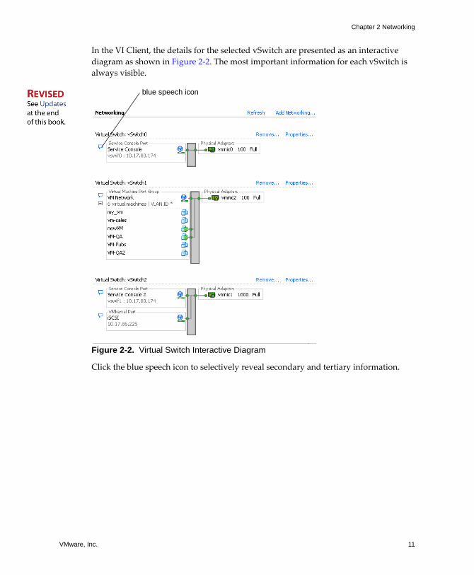
In the VI Client, the details for the selected vSwitch are presented as an interactive diagram as shown in Figure 2‐2. The most important information for each vSwitch is always visible.
Figure 2-2. Virtual Switch Interactive Diagram
Click the blue speech icon to selectively reveal secondary and tertiary information.
blue speech icon
Server Configuration Guide
12 VMware, Inc.
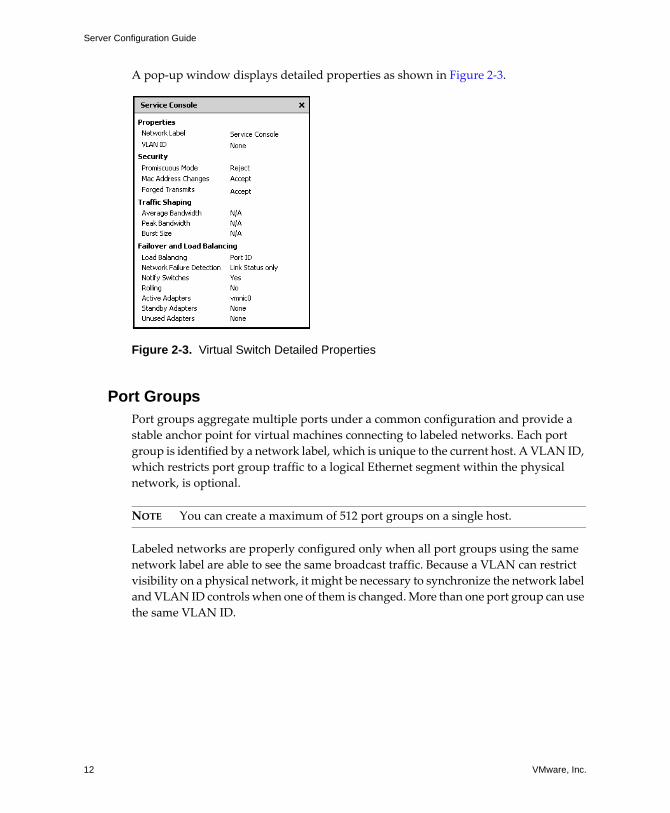
A pop‐up window displays detailed properties as shown in Figure 2‐3.
Figure 2-3. Virtual Switch Detailed Properties
Port GroupsPort groups aggregate multiple ports under a common configuration and provide a stable anchor point for virtual machines connecting to labeled networks. Each port group is identified by a network label, which is unique to the current host. A VLAN ID, which restricts port group traffic to a logical Ethernet segment within the physical network, is optional.
NOTE You can create a maximum of 512 port groups on a single host.
Labeled networks are properly configured only when all port groups using the same network label are able to see the same broadcast traffic. Because a VLAN can restrict visibility on a physical network, it might be necessary to synchronize the network label and VLAN ID controls when one of them is changed. More than one port group can use the same VLAN ID.
VMware, Inc. 13
Chapter 2 Networking
Network ServicesYou need to enable two types of network services in ESX Server:
! Connecting virtual machines to the physical network
! Connecting VMkernel services (such as NFS, iSCSI, or VMotion) to the physical network
The service console, which runs the management services, is set up by default during the installation of ESX Server.
Viewing Networking Information in the VI ClientThe VI Client displays both general networking information and information specific to network adapters.
To view general networking information in the VI Client
1 Log on to the VMware VI Client and select the server from the inventory panel.
The hardware configuration page for this server appears.
2 Click the Configuration tab, and click Networking.
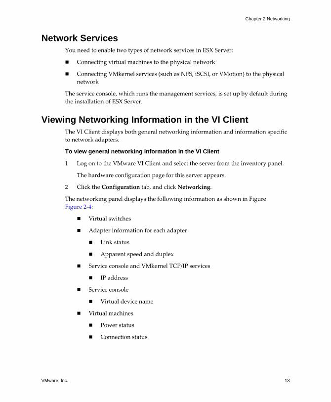
The networking panel displays the following information as shown in Figure Figure 2‐4:
! Virtual switches
! Adapter information for each adapter
! Link status
! Apparent speed and duplex
! Service console and VMkernel TCP/IP services
! IP address
! Service console
! Virtual device name
! Virtual machines
! Power status
! Connection status
Server Configuration Guide
14 VMware, Inc.
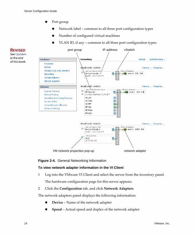
! Port group
! Network label � common to all three port configuration types
! Number of configured virtual machines
! VLAN ID, if any � common to all three port configuration types
Figure 2-4. General Networking Information
To view network adapter information in the VI Client
1 Log into the VMware VI Client and select the server from the inventory panel.
The hardware configuration page for this server appears.
2 Click the Configuration tab, and click Network Adapters.
The network adapters panel displays the following information:
! Device � Name of the network adapter
! Speed � Actual speed and duplex of the network adapter
IP address vSwitch
VM network properties pop-up network adapter
port group
VMware, Inc. 15
Chapter 2 Networking
! Configured � Configured speed and duplex of the network adapter
! vSwitch � vSwitch that the network adapter is associated with
! Networks � IP addresses that the network adapter has access to
Networking TasksThis chapter outlines how to perform the following networking tasks
! �To create or add a virtual network for a virtual machine� on page 16
! Setting the connection type for a virtual machine.
! Adding the virtual network to a new or an existing virtual switch.
! Configuring the network label and VLAN ID connection settings.
! �To set up the VMkernel� on page 20
! Setting the connection type for the VMkernel.
! Adding the virtual network to a new or an existing virtual switch.
! Configuring the network label, VLAN ID, TCP/IP, and gateway connection settings.
! �To configure service console networking� on page 24
! Setting the connection type for the service console.
! Adding the virtual network to a new or an existing virtual switch.
! Configuring the network label, VLAN ID, DHCP/Static IP, and gateway connection settings.
! �To set the default gateway� on page 28
! �To display service console information� on page 29
Virtual Network Configuration for Virtual MachinesThe VI Client Add Network Wizard steps you through the tasks to create a virtual network for a virtual machine. These tasks include:
! Setting the connection type for a virtual machine
! Adding the virtual network to a new or an existing vSwitch
! Configuring the connection settings for the network label and the VLAN ID
Server Configuration Guide
16 VMware, Inc.
To create or add a virtual network for a virtual machine
1 Log on to the VMware VI Client and select the server from the inventory panel.
The hardware configuration page for this server appears.
2 Click the Configuration tab, and click Networking.
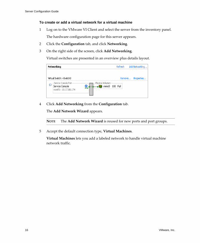
3 On the right side of the screen, click Add Networking.
Virtual switches are presented in an overview plus details layout.
4 Click Add Networking from the Configuration tab.
The Add Network Wizard appears.
NOTE The Add Network Wizard is reused for new ports and port groups.
5 Accept the default connection type, Virtual Machines.
Virtual Machines lets you add a labeled network to handle virtual machine network traffic.
VMware, Inc. 17
Chapter 2 Networking
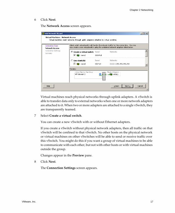
6 Click Next.
The Network Access screen appears.
Virtual machines reach physical networks through uplink adapters. A vSwitch is able to transfer data only to external networks when one or more network adapters are attached to it. When two or more adapters are attached to a single vSwitch, they are transparently teamed.
7 Select Create a virtual switch.
You can create a new vSwitch with or without Ethernet adapters.
If you create a vSwitch without physical network adapters, then all traffic on that vSwitch will be confined to that vSwitch. No other hosts on the physical network or virtual machines on other vSwitches will be able to send or receive traffic over this vSwitch. You might do this if you want a group of virtual machines to be able to communicate with each other, but not with other hosts or with virtual machines outside the group.
Changes appear in the Preview pane.
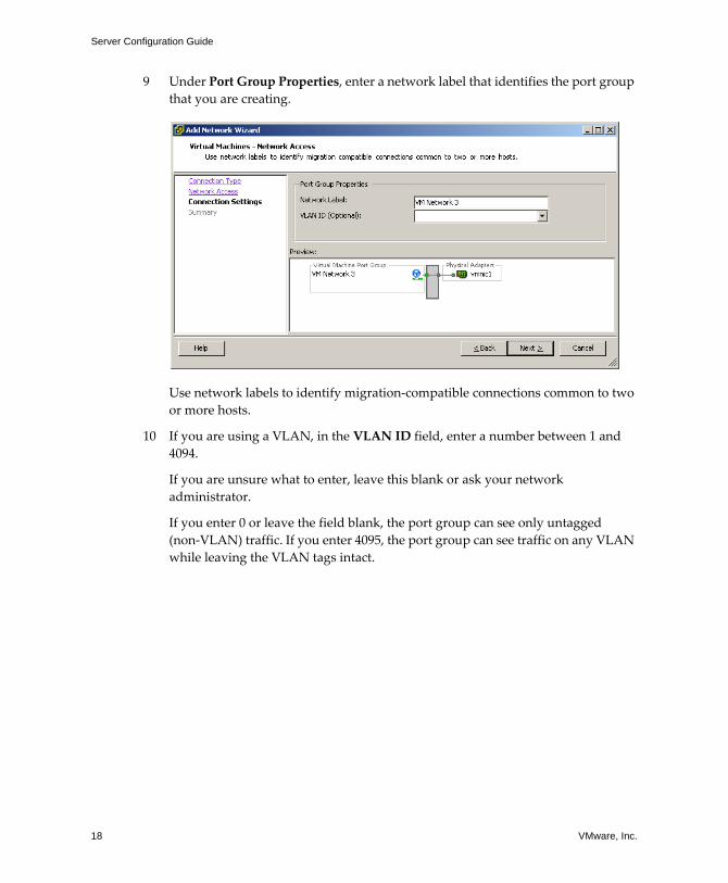
8 Click Next.
The Connection Settings screen appears.
Server Configuration Guide
18 VMware, Inc.
9 Under Port Group Properties, enter a network label that identifies the port group that you are creating.
Use network labels to identify migration‐compatible connections common to two or more hosts.
10 If you are using a VLAN, in the VLAN ID field, enter a number between 1 and 4094.
If you are unsure what to enter, leave this blank or ask your network administrator.
If you enter 0 or leave the field blank, the port group can see only untagged (non‐VLAN) traffic. If you enter 4095, the port group can see traffic on any VLAN while leaving the VLAN tags intact.
VMware, Inc. 19
Chapter 2 Networking
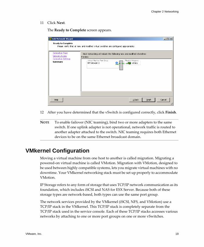
11 Click Next.
The Ready to Complete screen appears.
12 After you have determined that the vSwitch is configured correctly, click Finish.
NOTE To enable failover (NIC teaming), bind two or more adapters to the same switch. If one uplink adapter is not operational, network traffic is routed to another adapter attached to the switch. NIC teaming requires both Ethernet devices to be on the same Ethernet broadcast domain.
VMkernel ConfigurationMoving a virtual machine from one host to another is called migration. Migrating a powered‐on virtual machine is called VMotion. Migration with VMotion, designed to be used between highly compatible systems, lets you migrate virtual machines with no downtime. Your VMkernel networking stack must be set up properly to accommodate VMotion.
IP Storage refers to any form of storage that uses TCP/IP network communication as its foundation, which includes iSCSI and NAS for ESX Server. Because both of these storage types are network‐based, both types can use the same port group.
The network services provided by the VMkernel (iSCSI, NFS, and VMotion) use a TCP/IP stack in the VMkernel. This TCP/IP stack is completely separate from the TCP/IP stack used in the service console. Each of these TCP/IP stacks accesses various networks by attaching to one or more port groups on one or more vSwitches.
Server Configuration Guide
20 VMware, Inc.
TCP/IP Stack at the Virtual Machine Monitor LevelThe VMware VMkernel TCP/IP networking stack has been extended to handle iSCSI, NFS, and VMotion in the following ways:
! iSCSI as a virtual machine datastore.
! iSCSI for the direct mounting of .ISO files, which are presented as CD‐ROMs to virtual machines.
! NFS as a virtual machine datastore.
! NFS for the direct mounting of .ISO files, which are presented as CD‐ROMs to virtual machines.
! Migration with VMotion.
NOTE ESX supports only NFS version 3 over TCP/IP.
Implications and GuidelinesRefer to the following guidelines when configuring VMkernel networking:
! The IP address that you assign to the service console during installation must be different from the IP address that you assign to VMkernel�s TCP/IP stack from the Configuration > Networking tab of the Virtual Infrastructure Client.
! Before configuring software iSCSI for the ESX Server host, open a firewall port by enabling the iSCSI software client service. For more information, see �Opening Firewall Ports for Supported Services and Management Agents� on page 185.
! Unlike other VMkernel services, iSCSI has a service console component, so networks that are used to reach iSCSI targets must be accessible to both service console and VMkernel TCP/IP stacks.
To set up the VMkernel
1 Log on to the VMware VI Client and select the server from the inventory panel.
The hardware configuration page for this server appears.
2 Click the Configuration tab, and click Networking.
3 Click the Add Networking link.
The Add Network Wizard appears.
VMware, Inc. 21
Chapter 2 Networking
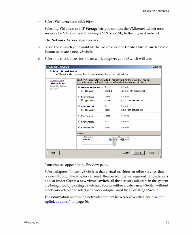
4 Select VMkernel and click Next.
Selecting VMotion and IP Storage lets you connect the VMkernel, which runs services for VMotion and IP storage (NFS or iSCSI), to the physical network.
The Network Access page appears.
5 Select the vSwitch you would like to use, or select the Create a virtual switch radio button to create a new vSwitch.
6 Select the check boxes for the network adapters your vSwitch will use.
Your choices appear in the Preview pane.
Select adapters for each vSwitch so that virtual machines or other services that connect through the adapter can reach the correct Ethernet segment. If no adapters appear under Create a new virtual switch, all the network adapters in the system are being used by existing vSwitches. You can either create a new vSwitch without a network adapter or select a network adapter used by an existing vSwitch.
For information on moving network adapters between vSwitches, see �To add uplink adapters� on page 36.
Server Configuration Guide
22 VMware, Inc.
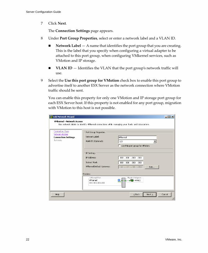
7 Click Next.
The Connection Settings page appears.
8 Under Port Group Properties, select or enter a network label and a VLAN ID.
! Network Label � A name that identifies the port group that you are creating. This is the label that you specify when configuring a virtual adapter to be attached to this port group, when configuring VMkernel services, such as VMotion and IP storage.
! VLAN ID � Identifies the VLAN that the port group�s network traffic will use.
9 Select the Use this port group for VMotion check box to enable this port group to advertise itself to another ESX Server as the network connection where VMotion traffic should be sent.
You can enable this property for only one VMotion and IP storage port group for each ESX Server host. If this property is not enabled for any port group, migration with VMotion to this host is not possible.
VMware, Inc. 23
Chapter 2 Networking
10 Under IP Settings, click Edit to set the VMkernel Default Gateway for VMkernel services, such as VMotion, NAS, and iSCSI.
NOTE Make sure that you set a default gateway for the port that you created. VirtualCenter 2 behaves differently here from VirtualCenter 1.x. You must use a valid IP address to configure the VMkernel IP stack, not a dummy address.
The DNS and Routing Configuration dialog box appears. Under the DNS Configuration tab, the name of the host is entered into the name field by default. The DNS server addresses that were specified during installation are also preselected as is the domain.
Under the Routing tab, the service console and the VMkernel each need their own gateway information. A gateway is for needed if connectivity to machines not on the same IP subnet as the service console or VMkernel.
Static IP settings is the default.
11 Click OK to save your changes and close the DNS Configuration and Routing dialog box.
12 Click Next.
13 Use the Back button to make any changes.
14 Review your changes on the Ready to Complete page and click Finish.
Service Console ConfigurationBoth the service console and the VMkernel use virtual Ethernet adapters to connect to a vSwitch and to reach networks serviced by the vSwitch.
Basic Service Console Configuration TasksThere are two common service console configuration changes: changing NICs and changing the settings for an existing NIC that is in use.
When only one service console connection is present, changing the service console configuration is not allowed. If you want a new connection, you must change the network settings to use an additional NIC. After verifying that the new connection is functioning properly, remove the old connection. You are switching over to the new NIC.
Server Configuration Guide
24 VMware, Inc.
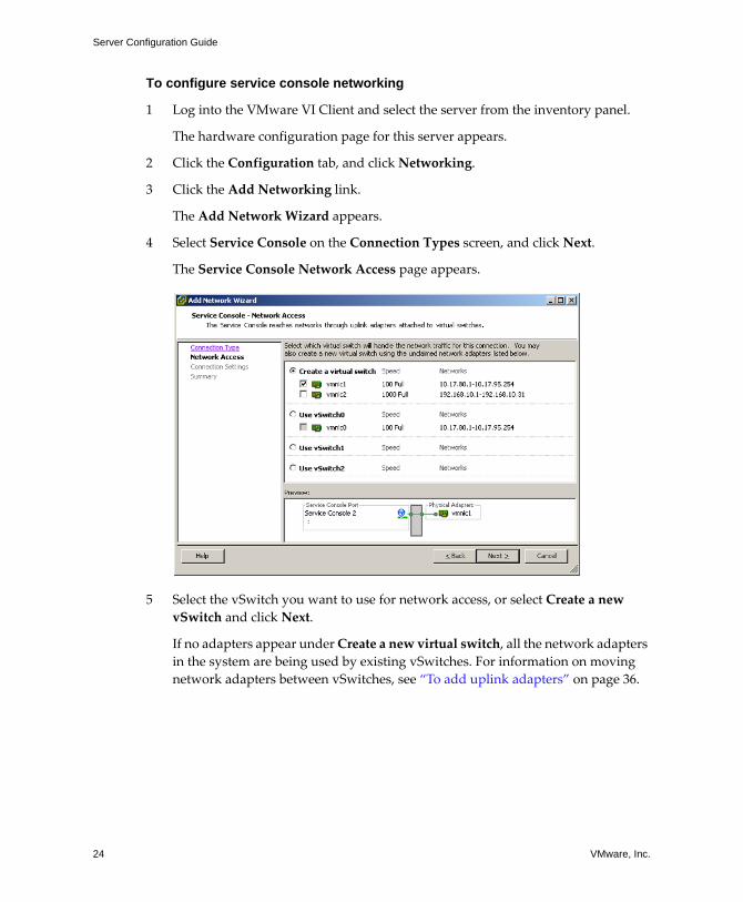
To configure service console networking
1 Log into the VMware VI Client and select the server from the inventory panel.
The hardware configuration page for this server appears.
2 Click the Configuration tab, and click Networking.
3 Click the Add Networking link.
The Add Network Wizard appears.
4 Select Service Console on the Connection Types screen, and click Next.
The Service Console Network Access page appears.
5 Select the vSwitch you want to use for network access, or select Create a new vSwitch and click Next.
If no adapters appear under Create a new virtual switch, all the network adapters in the system are being used by existing vSwitches. For information on moving network adapters between vSwitches, see �To add uplink adapters� on page 36.
VMware, Inc. 25
Chapter 2 Networking
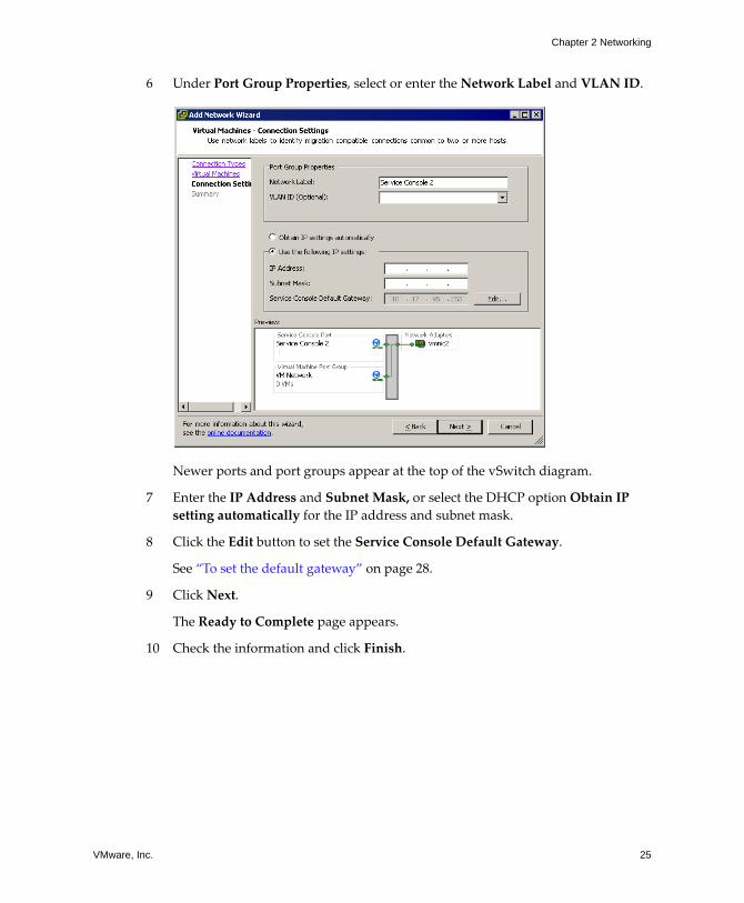
6 Under Port Group Properties, select or enter the Network Label and VLAN ID.
Newer ports and port groups appear at the top of the vSwitch diagram.
7 Enter the IP Address and Subnet Mask, or select the DHCP option Obtain IP setting automatically for the IP address and subnet mask.
8 Click the Edit button to set the Service Console Default Gateway.
See �To set the default gateway� on page 28.
9 Click Next.
The Ready to Complete page appears.
10 Check the information and click Finish.
Server Configuration Guide
26 VMware, Inc.
To configure service console ports
1 Log into the VMware VI Client and select the server from the inventory panel.
The hardware configuration page for this server appears.
2 Click the Configuration tab, and click Networking.
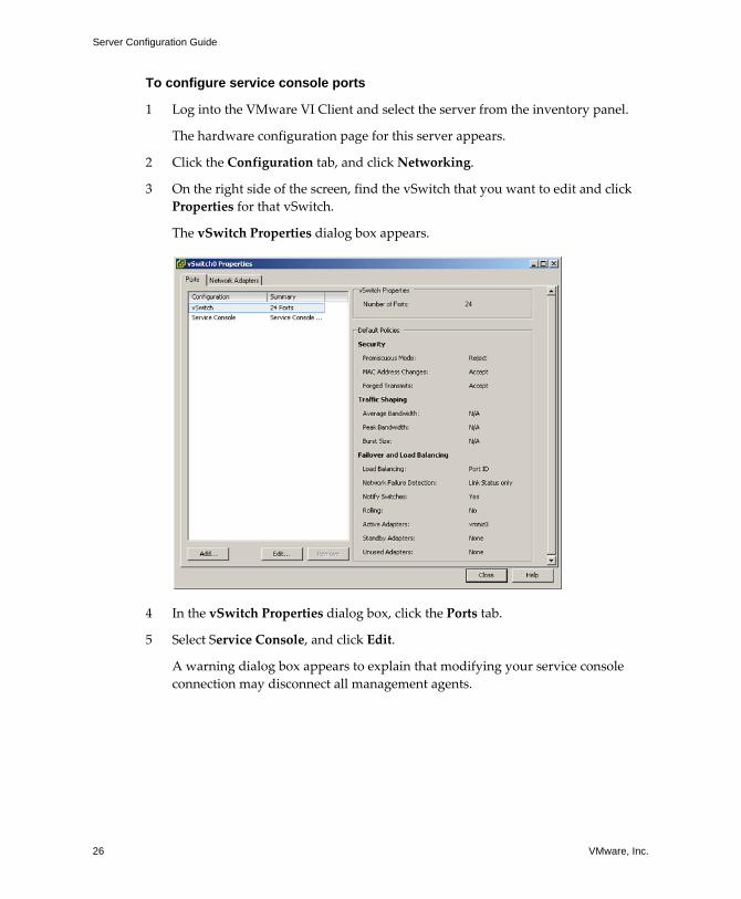
3 On the right side of the screen, find the vSwitch that you want to edit and click Properties for that vSwitch.
The vSwitch Properties dialog box appears.
4 In the vSwitch Properties dialog box, click the Ports tab.
5 Select Service Console, and click Edit.
A warning dialog box appears to explain that modifying your service console connection may disconnect all management agents.
VMware, Inc. 27
Chapter 2 Networking
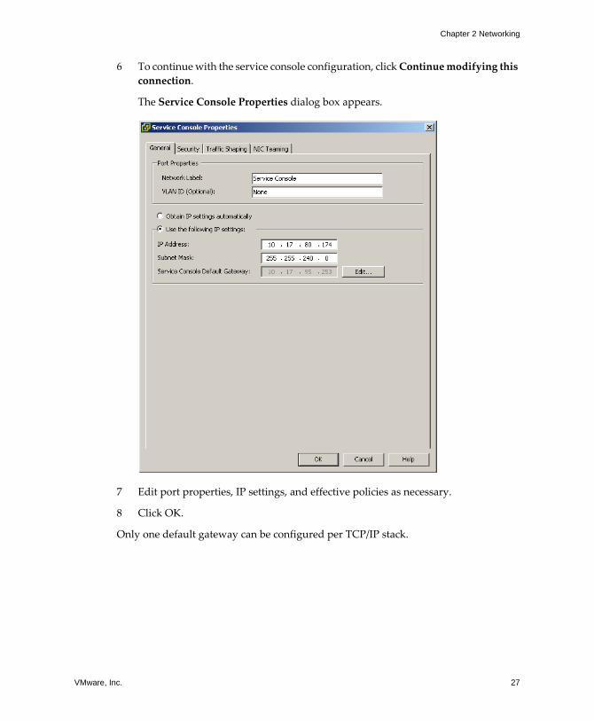
6 To continue with the service console configuration, click Continue modifying this connection.
The Service Console Properties dialog box appears.
7 Edit port properties, IP settings, and effective policies as necessary.
8 Click OK.
Only one default gateway can be configured per TCP/IP stack.
Server Configuration Guide
28 VMware, Inc.
To set the default gateway
1 Log into the VMware VI Client and select the server from the inventory panel.
The hardware configuration page for this server appears.
2 Click the Configuration tab, and click DNS and Routing.
The DNS and Routing panel appears.
3 Click the Properties link.
The DNS Configuration dialog box appears.
Under the DNS Configuration tab, the name of the host is entered into the name field by default. The DNS server addresses and the domain previously selected during installation are also preselected.
Under the Routing tab, the service console and the VMkernel are often not connected to the same network, and each needs its own gateway information. A gateway is needed for connectivity to machines not on the same IP subnet as the service console or VMkernel.
NOTE All NAS and iSCSI servers need to be either reachable by the default gateway or on the same broadcast domain as the associated vSwitches.
For the service console, the gateway device is needed only when two or more network adapters are using the same subnet. The gateway device determines which network adapter will be used for the default route.
4 Click the Routing tab.
5 Set the VMkernel default gateway.
CAUTION There is a risk of misconfiguration, which can cause the UI to lose connectivity to the host, in which case the host will have to be reconfigured from command line at the service console.
6 Click OK to save your changes and close the DNS Configuration dialog box.
VMware, Inc. 29
Chapter 2 Networking
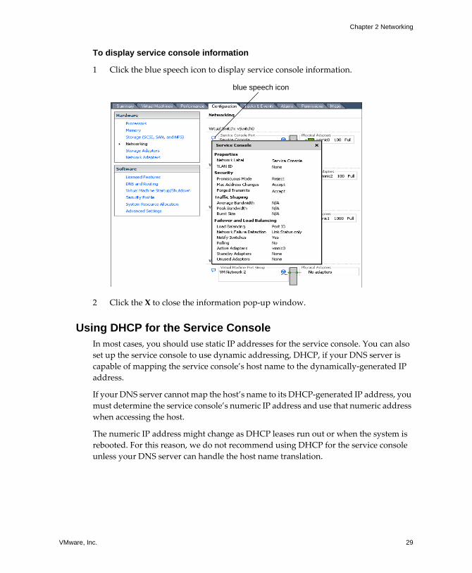
To display service console information
1 Click the blue speech icon to display service console information.
2 Click the X to close the information pop‐up window.
Using DHCP for the Service ConsoleIn most cases, you should use static IP addresses for the service console. You can also set up the service console to use dynamic addressing, DHCP, if your DNS server is capable of mapping the service console�s host name to the dynamically‐generated IP address.
If your DNS server cannot map the host�s name to its DHCP‐generated IP address, you must determine the service console�s numeric IP address and use that numeric address when accessing the host.
The numeric IP address might change as DHCP leases run out or when the system is rebooted. For this reason, we do not recommend using DHCP for the service console unless your DNS server can handle the host name translation.
blue speech icon

Server Configuration Guide
30 VMware, Inc.
VMware, Inc. 31
CHAPTER 3 Advanced Networking
This chapter guides you through advanced networking topics in an ESX Server environment and how to set up and change advanced networking configuration options.
This chapter covers the following topics:
! �Advanced Networking Tasks� on page 32
! �Virtual Switch Configuration� on page 32
! �Port Group Configuration� on page 46
! �DNS and Routing� on page 48
! �Setting Up MAC Addresses� on page 50
! �Networking Tips and Best Practices� on page 53
Server Configuration Guide
32 VMware, Inc.
Advanced Networking TasksThis chapter outlines how to perform the following advanced networking tasks:
! �To edit the number of ports for a vSwitch� on page 32
! �To configure the uplink network adapter by changing its speed� on page 35
! �To add uplink adapters� on page 36
! �To edit the Layer 2 Security policy� on page 39
! �To edit the Traffic Shaping policy� on page 41
! �To edit the failover and load balancing policy� on page 43
! �To edit port group properties� on page 46
! �To override labeled network policies� on page 47
! �To change the DNS and Routing configuration� on page 48
! �To set up a MAC address� on page 52
Virtual Switch ConfigurationThis section contains the following information:
! �Virtual Switch Properties� on page 32
! �Virtual Switch Policies� on page 39
Virtual Switch Properties
Virtual switch settings control vSwitch‐wide defaults for ports, which can be overridden by port group settings for each vSwitch.
Editing Virtual Switch PropertiesEditing vSwitch properties consists of:
! Configuring ports
! Configuring the uplink network adapters
To edit the number of ports for a vSwitch
1 Log into the VMware VI Client, and select the server from the inventory panel.
The hardware configuration page for this server appears.
2 Click the Configuration tab, and click Networking.
VMware, Inc. 33
Chapter 3 Advanced Networking
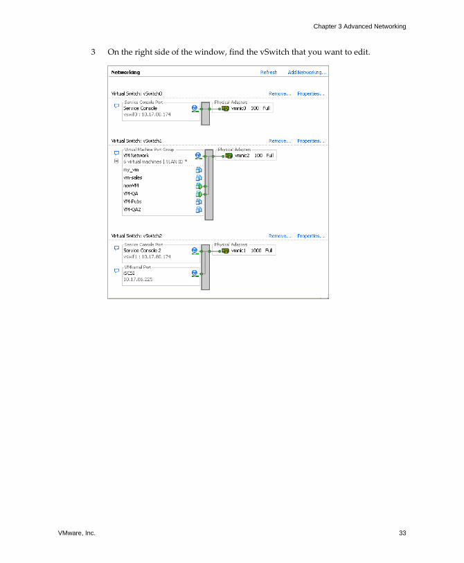
3 On the right side of the window, find the vSwitch that you want to edit.
Server Configuration Guide
34 VMware, Inc.
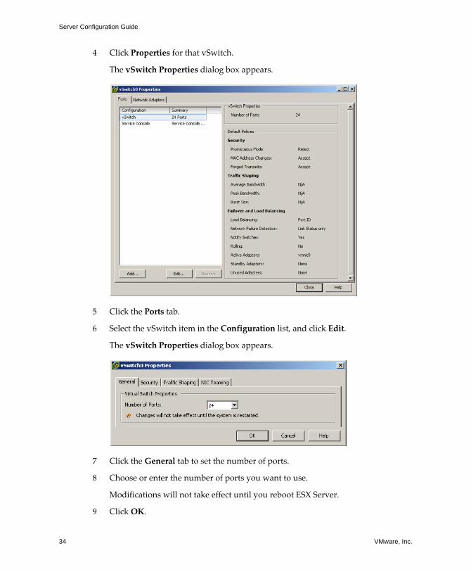
4 Click Properties for that vSwitch.
The vSwitch Properties dialog box appears.
5 Click the Ports tab.
6 Select the vSwitch item in the Configuration list, and click Edit.
The vSwitch Properties dialog box appears.
7 Click the General tab to set the number of ports.
8 Choose or enter the number of ports you want to use.
Modifications will not take effect until you reboot ESX Server.
9 Click OK.
VMware, Inc. 35
Chapter 3 Advanced Networking
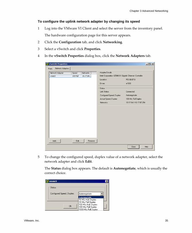
To configure the uplink network adapter by changing its speed
1 Log into the VMware VI Client and select the server from the inventory panel.
The hardware configuration page for this server appears.
2 Click the Configuration tab, and click Networking.
3 Select a vSwitch and click Properties.
4 In the vSwitch Properties dialog box, click the Network Adapters tab.
5 To change the configured speed, duplex value of a network adapter, select the network adapter and click Edit.
The Status dialog box appears. The default is Autonegotiate, which is usually the correct choice.

Server Configuration Guide
36 VMware, Inc.
6 To select the connection speed manually, select the speed/duplex from the drop‐down menu.
Choose the connection speed manually if the NIC and a physical switch might fail to negotiate the proper connection speed. Symptoms of mismatched speed and duplex include low bandwidth or no link connectivity at all.
The adapter and the physical switch port it is connected to must be set to the same value, that is, auto/auto or ND/ND where ND is some speed and duplex, but not auto/ND.
7 Click OK.
To add uplink adapters
1 Log into the VMware VI Client, and select the server from the inventory panel.
The hardware configuration page for this server appears.
2 Click the Configuration tab, and click Networking.
3 Select a vSwitch and click Properties.
4 In the Properties dialog box for the vSwitch, click the Network Adapters tab.
VMware, Inc. 37
Chapter 3 Advanced Networking
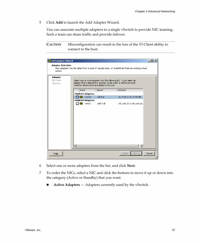
5 Click Add to launch the Add Adapter Wizard.
You can associate multiple adapters to a single vSwitch to provide NIC teaming. Such a team can share traffic and provide failover.
CAUTION Misconfiguration can result in the loss of the VI Client ability to connect to the host.
6 Select one or more adapters from the list, and click Next.
7 To order the NICs, select a NIC and click the buttons to move it up or down into the category (Active or Standby) that you want.
! Active Adapters � Adapters currently used by the vSwitch.
Server Configuration Guide
38 VMware, Inc.
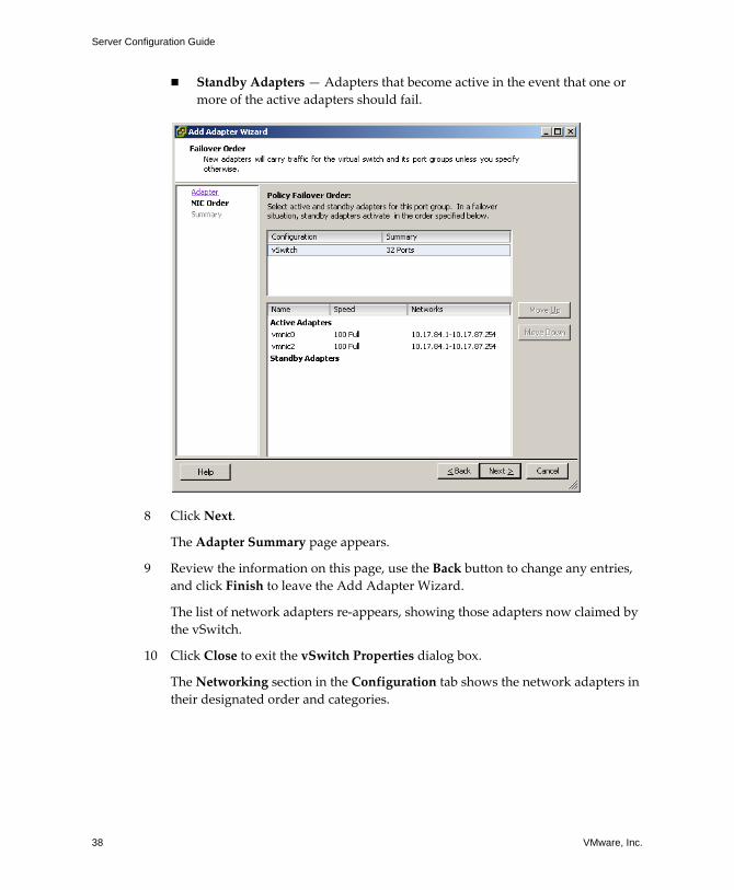
! Standby Adapters � Adapters that become active in the event that one or more of the active adapters should fail.
8 Click Next.
The Adapter Summary page appears.
9 Review the information on this page, use the Back button to change any entries, and click Finish to leave the Add Adapter Wizard.
The list of network adapters re‐appears, showing those adapters now claimed by the vSwitch.
10 Click Close to exit the vSwitch Properties dialog box.
The Networking section in the Configuration tab shows the network adapters in their designated order and categories.
VMware, Inc. 39
Chapter 3 Advanced Networking
Virtual Switch Policies
You can apply a set of vSwitch‐wide policies by selecting the vSwitch at the top of the Ports tab and clicking Edit.
To override any of these settings for a port group, select that port group and click Edit. Any changes to the vSwitch‐wide configuration are applied to any of the port groups on that vSwitch except for those configuration options that have been overridden by the port group.
The vSwitch policies consist of:
! Layer 2 Security policy
! Traffic Shaping policy
! Load Balancing and Failover policy
Layer 2 Security PolicyLayer 2 is the data link layer. The three elements of the Layer 2 Security policy are promiscuous mode, MAC address changes, and forged transmits.
In non‐promiscuous mode, a guest adapter listens to traffic only on its own MAC address. In promiscuous mode, it can listen to all the packets. By default, guest adapters are set to non‐promiscuous mode.
For further information on security, see �Securing Virtual Switch Ports� on page 195.
To edit the Layer 2 Security policy
1 Log into the VMware VI Client and select the server from the inventory panel.
The hardware configuration page for this server appears.
2 Click the Configuration tab, and click Networking.
3 Click Properties for the vSwitch whose Layer 2 Security policy you want to edit.
4 In the Properties dialog box for the vSwitch, click the Ports tab.
5 Select the vSwitch item and click Edit.
Server Configuration Guide
40 VMware, Inc.
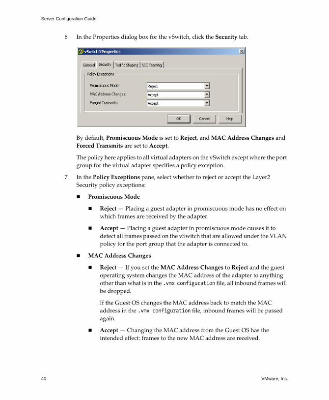
6 In the Properties dialog box for the vSwitch, click the Security tab.
By default, Promiscuous Mode is set to Reject, and MAC Address Changes and Forced Transmits are set to Accept.
The policy here applies to all virtual adapters on the vSwitch except where the port group for the virtual adapter specifies a policy exception.
7 In the Policy Exceptions pane, select whether to reject or accept the Layer2 Security policy exceptions:
! Promiscuous Mode
! Reject � Placing a guest adapter in promiscuous mode has no effect on which frames are received by the adapter.
! Accept � Placing a guest adapter in promiscuous mode causes it to detect all frames passed on the vSwitch that are allowed under the VLAN policy for the port group that the adapter is connected to.
! MAC Address Changes
! Reject � If you set the MAC Address Changes to Reject and the guest operating system changes the MAC address of the adapter to anything other than what is in the .vmx configuration file, all inbound frames will be dropped.
If the Guest OS changes the MAC address back to match the MAC address in the .vmx configuration file, inbound frames will be passed again.
! Accept � Changing the MAC address from the Guest OS has the intended effect: frames to the new MAC address are received.
VMware, Inc. 41
Chapter 3 Advanced Networking
! Forged Transmits
! Reject � Any outbound frame with a source MAC address that is different from the one currently set on the adapter will be dropped.
! Accept � No filtering is performed and all outbound frames are passed.
8 Click OK.
Traffic Shaping Policy
ESX Server shapes traffic by establishing parameters for three outbound traffic characteristics: average bandwidth, burst size, and peak bandwidth. You can set values for these characteristics through the VI Client, establishing a traffic shaping policy for each uplink adapter.
! Average Bandwidth establishes the number of bits per second to allow across the vSwitch averaged over time�the allowed average load.
! Burst Size establishes the maximum number of bytes to allow in a burst. If a burst exceeds the burst size parameter, excess packets are queued for later transmission. If the queue is full, the packets are dropped. When you specify values for these two characteristics, you indicate what you expect the vSwitch to handle during normal operation.
! Peak Bandwidth is the maximum bandwidth the vSwitch can absorb without dropping packets. If traffic exceeds the peak bandwidth you establish, excess packets are queued for later transmission after traffic on the connection has returned to the average and there are enough spare cycles to handle the queued packets. If the queue is full, the packets are dropped. Even if you have spare bandwidth because the connection has been idle, the peak bandwidth parameter limits transmission to no more than peak until traffic returns to the allowed average load.
To edit the Traffic Shaping policy
1 Log into the VMware VI Client and select the server from the inventory panel.
The hardware configuration page for this server appears.
2 Click the Configuration tab, and click Networking.
3 Select a vSwitch and click Properties.
4 In the vSwitch Properties dialog box, click the Ports tab.
5 Select the vSwitch and click Edit.
The Properties dialog box for the selected vSwitch appears.
Server Configuration Guide
42 VMware, Inc.
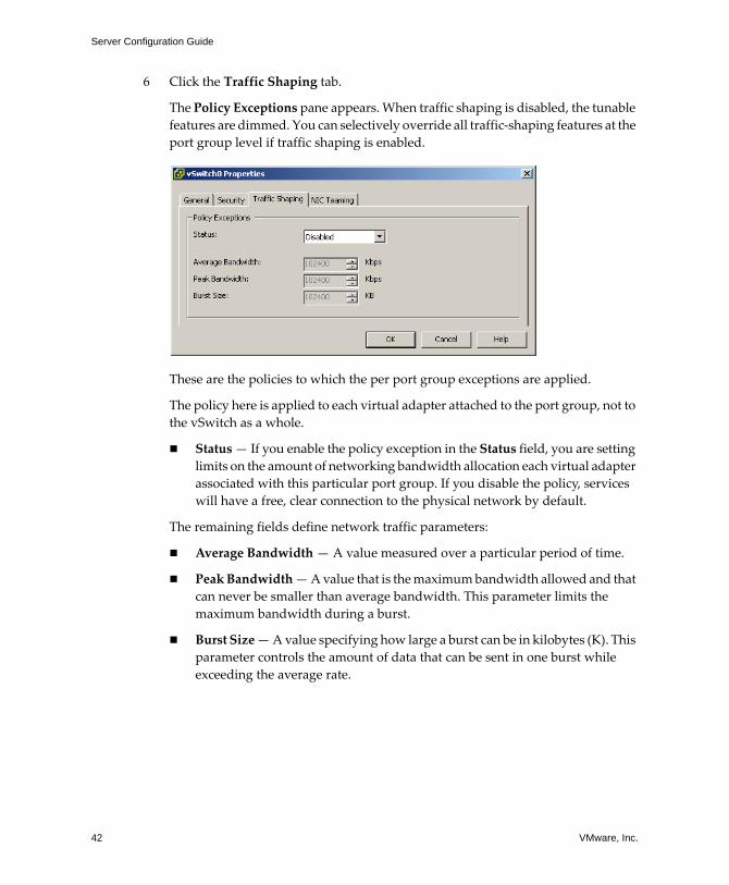
6 Click the Traffic Shaping tab.
The Policy Exceptions pane appears. When traffic shaping is disabled, the tunable features are dimmed. You can selectively override all traffic‐shaping features at the port group level if traffic shaping is enabled.
These are the policies to which the per port group exceptions are applied.
The policy here is applied to each virtual adapter attached to the port group, not to the vSwitch as a whole.
! Status � If you enable the policy exception in the Status field, you are setting limits on the amount of networking bandwidth allocation each virtual adapter associated with this particular port group. If you disable the policy, services will have a free, clear connection to the physical network by default.
The remaining fields define network traffic parameters:
! Average Bandwidth � A value measured over a particular period of time.
! Peak Bandwidth � A value that is the maximum bandwidth allowed and that can never be smaller than average bandwidth. This parameter limits the maximum bandwidth during a burst.
! Burst Size � A value specifying how large a burst can be in kilobytes (K). This parameter controls the amount of data that can be sent in one burst while exceeding the average rate.
VMware, Inc. 43
Chapter 3 Advanced Networking
Load Balancing and Failover PolicyLoad Balancing and Failover policies allow you to determine how network traffic is distributed between adapters and how to re‐route traffic in the event of an adapter failure by configuring the following parameters:
! Load Balancing policy
The Load Balancing policy determines how incoming and outgoing traffic is distributed among the network adapters assigned to a vSwitch.
! Failover Detection: Link Status/Beacon Probing
! Network Adapter Order (Active/Standby)
To edit the failover and load balancing policy
1 Log into the VMware VI Client and select the server from the inventory panel.
The hardware configuration page for this server appears.
2 Click the Configuration tab, and click Networking.
3 Select a vSwitch and click Edit.
4 In the vSwitch Properties dialog box, click the Ports tab.
5 To edit the Failover and Load Balancing values for the vSwitch, select the vSwitch item and click Properties.
The Properties dialog box for the vSwitch appears.

Server Configuration Guide
44 VMware, Inc.
6 Click the NIC Teaming tab.
The Policy Exceptions area appears. You can override the failover order at the port group level. By default, new adapters are active for all policies. New adapters carry traffic for the vSwitch and its port group unless you specify otherwise.
7 In the Policy Exceptions pane:
! Load Balancing � Specify how to choose an uplink.
! Route based on the originating port ID � Choose an uplink based on the virtual port where the traffic entered the virtual switch.
! Route based on ip hash � Choose an uplink based on a hash of the source and destination IP addresses of each packet. For non‐IP packets, whatever is at those offsets is used to compute the hash.

VMware, Inc. 45
Chapter 3 Advanced Networking
! Route based on source MAC hash � Choose an uplink based on a hash of the source Ethernet.
! Use explicit failover order � Always use the highest order uplink from the list of Active adapters which passes failover detection criteria.
! Network Failover Detection � Specify the method to use for failover detection.
! Link Status only � Relies solely on the link status provided by the network adapter. This detects failures, such as cable pulls and physical switch power failures, but not configuration errors, such as a physical switch port being blocked by spanning tree or misconfigured to the wrong VLAN or cable pulls on the other side of a physical switch.
! Beacon Probing � Sends out and listens for beacon probes on all NICs in the team and uses this information, in addition to link status, to determine link failure. This detects many of the failures mentioned above that are not detected by link status alone.
! Notify Switches � Select Yes or No to notify switches in the case of failover.
If you select Yes, whenever a virtual NIC is connected to the vSwitch or whenever that virtual NIC�s traffic would be routed over a different physical NIC in the team due to a failover event, a notification is sent out over the network to update the lookup tables on physical switches. In almost all cases, this is desirable for the lowest latency of failover occurrences and migrations with VMotion.
NOTE Do not use this option when the virtual machines using the port group are using Microsoft Network Load Balancing in unicast mode. No such issue exists with NLB running in multicast mode.
! Rolling Failover� Select Yes or No to disable or enable rolling.
This option determines how a physical adapter is returned to active duty after recovering from a failure. If rolling is set to No, the adapter is returned to active duty immediately upon recovery, displacing the standby adapter that took over its slot, if any. If rolling is set to Yes, a failed adapter is left inactive even after recovery until another currently active adapter fails, requiring its replacement.
Server Configuration Guide
46 VMware, Inc.
! Failover Order � Specify how to distribute the work load for adapters. If you want to use some adapters but reserve others for emergencies in case the ones in use fail, you can set this condition using the drop‐down menu to place them into the two groups:
! Active Adapters � Continue to use it when the network adapter connectivity is up and active.
! Standby Adapters � Use this adapter if one of the active adapter�s connectivity is down.
! Unused Adapters � Not to be used.
Port Group ConfigurationYou can change the following port group configurations:
! Port group properties
! Labelled network policies
To edit port group properties
1 Log into the VMware VI Client, and select the server from the inventory panel.
The hardware configuration page for this server appears.
2 Click the Configuration tab, and click Networking.
3 On the right side of the window, click Properties for a network.
The vSwitch Properties dialog box appears.
4 Click the Ports tab.
5 Select the port group and click Edit.
6 In the Properties dialog box for the port group, click the General tab to change:
! Network Label � Identifies the port group that you are creating. Specify this label when configuring a virtual adapter to be attached to this port group, either when configuring virtual machines or VMkernel services, such as VMotion and IP storage.
! VLAN ID � Identifies the VLAN that the port group�s network traffic will use.
7 Click OK to exit the vSwitch Properties dialog box.
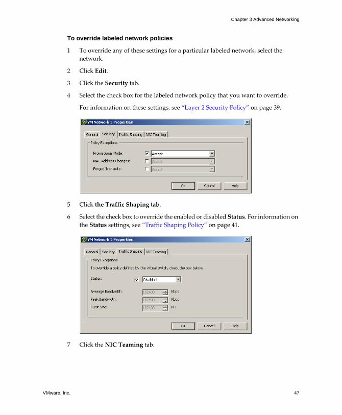
VMware, Inc. 47
Chapter 3 Advanced Networking
To override labeled network policies
1 To override any of these settings for a particular labeled network, select the network.
2 Click Edit.
3 Click the Security tab.
4 Select the check box for the labeled network policy that you want to override.
For information on these settings, see �Layer 2 Security Policy� on page 39.
5 Click the Traffic Shaping tab.
6 Select the check box to override the enabled or disabled Status. For information on the Status settings, see �Traffic Shaping Policy� on page 41.
7 Click the NIC Teaming tab.
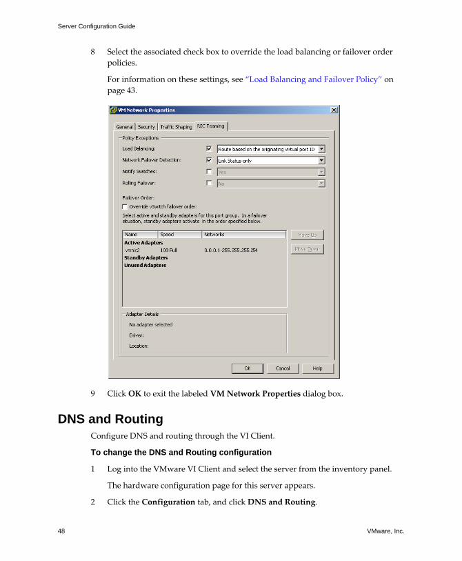
Server Configuration Guide
48 VMware, Inc.
8 Select the associated check box to override the load balancing or failover order policies.
For information on these settings, see �Load Balancing and Failover Policy� on page 43.
9 Click OK to exit the labeled VM Network Properties dialog box.
DNS and RoutingConfigure DNS and routing through the VI Client.
To change the DNS and Routing configuration
1 Log into the VMware VI Client and select the server from the inventory panel.
The hardware configuration page for this server appears.
2 Click the Configuration tab, and click DNS and Routing.
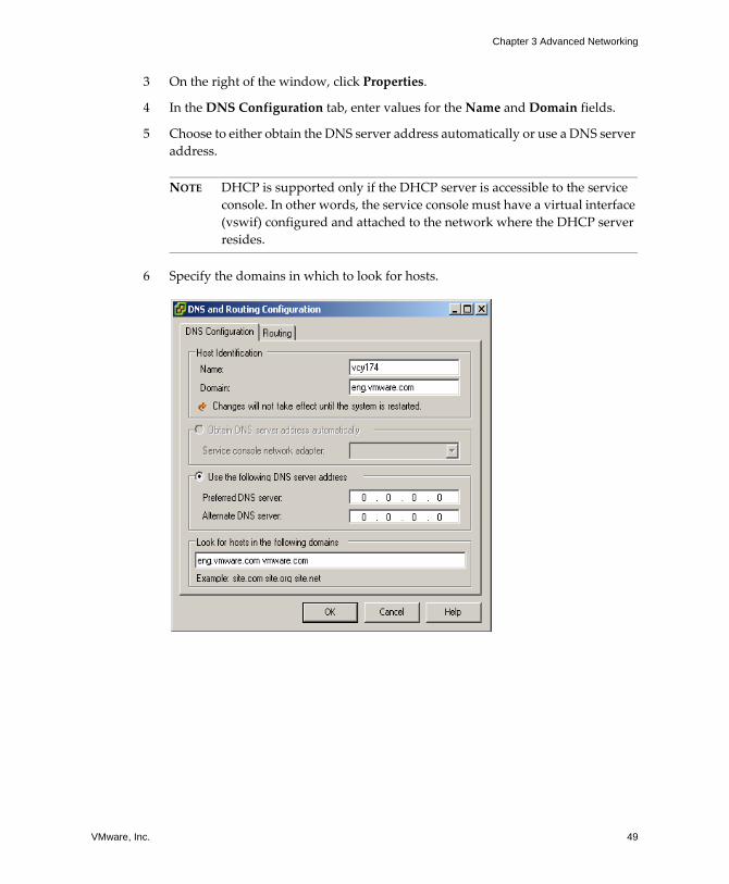
VMware, Inc. 49
Chapter 3 Advanced Networking
3 On the right of the window, click Properties.
4 In the DNS Configuration tab, enter values for the Name and Domain fields.
5 Choose to either obtain the DNS server address automatically or use a DNS server address.
NOTE DHCP is supported only if the DHCP server is accessible to the service console. In other words, the service console must have a virtual interface (vswif) configured and attached to the network where the DHCP server resides.
6 Specify the domains in which to look for hosts.
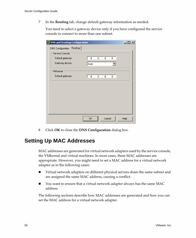
Server Configuration Guide
50 VMware, Inc.
7 In the Routing tab, change default gateway information as needed.
You need to select a gateway device only if you have configured the service console to connect to more than one subnet.
8 Click OK to close the DNS Configuration dialog box.
Setting Up MAC Addresses
MAC addresses are generated for virtual network adapters used by the service console, the VMkernal and virtual machines. In most cases, these MAC addresses are appropriate. However, you might need to set a MAC address for a virtual network adapter as in the following cases:
! Virtual network adapters on different physical servers share the same subnet and are assigned the same MAC address, causing a conflict.
! You want to ensure that a virtual network adapter always has the same MAC address.
The following sections describe how MAC addresses are generated and how you can set the MAC address for a virtual network adapter.
VMware, Inc. 51
Chapter 3 Advanced Networking
MAC Addresses GenerationEach virtual network adapter in a virtual machine is assigned its own unique MAC address. A MAC address is a six‐byte number. Each network adapter manufacturer is assigned a unique three‐byte prefix called an OUI (Organizationally Unique Identifier) that it can use to generate unique MAC addresses.
VMware has three OUIs:
! One for generated MAC addresses.
! One for manually set MAC addresses.
! One which was previously used for legacy virtual machines, but is no longer used with ESX Server 3.0.
The first three bytes of the MAC address that is generated for each virtual network adapter have this value. This MAC address generation algorithm produces the other three bytes. The algorithm guarantees unique MAC addresses within a machine and attempts to provide unique MAC addresses across machines.
The network adapters for each virtual machine on the same subnet should have unique MAC addresses. Otherwise, they can behave unpredictably. The algorithm puts a limit on the number of running and suspended virtual machines at any one time on any given server. It also does not handle all cases when virtual machines on distinct physical machines share a subnet.
The VMware UUID (Universally Unique Identifier) generates MAC addresses that are checked for any conflicts. The generated MAC addresses are created using three parts: the VMware OUI, the SMBIOS UUID for the physical ESX Server machine, and a hash based on the name of the entity that the MAC address is being generated for.
After the MAC address has been generated, it does not change unless the virtual machine is moved to a different location, for example, to a different path on the same server. The MAC address in the configuration file of the virtual machine is saved. All MAC addresses that have been assigned to network adapters of running and suspended virtual machines on a given physical machine are tracked.
The MAC address of a powered‐off virtual machine is not checked against those of running or suspended virtual machines. It is possible but unlikely that when a virtual machine is powered on again, it can acquire a different MAC address. This acquisition is due to a conflict with a virtual machine that was powered on when this virtual machine was powered off.
Server Configuration Guide
52 VMware, Inc.
Setting MAC Addresses To circumvent the limit of 256 virtual network adapters per physical machine and possible MAC address conflicts between virtual machines, system administrators can manually assign MAC addresses. VMware uses this OUI for manually‐generated addresses: 00:50:56.
The MAC address range is
00:50:56:00:00:00-00:50:56:3F:FF:FF
You can set the addresses by adding the following line to a virtual machine�s configuration file:
ethernet <number>.address = 00:50:56:XX:YY:ZZ
where <number> refers to the number of the Ethernet adapter, XX is a valid hexadecimal number between 00 and 3F, and YY and ZZ are valid hexadecimal numbers between 00 and FF. The value for XX must not be greater than 3F to avoid conflict with MAC addresses that are generated by the VMware Workstation and VMware GSX Server products. The maximum value for a manually generated MAC address is
ethernet<number>.address = 00:50:56:3F:FF:FF
You must also set the option in a virtual machine�s configuration file:
ethernet<number>.addressType="static"
Because VMware ESX Server virtual machines do not support arbitrary MAC addresses, the above format must be used. As long as you choose a unique value for XX:YY:ZZ among your hard‐coded addresses, conflicts between the automatically assigned MAC addresses and the manually assigned ones should never occur.
Using MAC AddressesThe easiest way to familiarize yourself with MAC addresses is to set up a MAC address.
To set up a MAC address
1 Set the MAC address statically.
2 Remove the virtual machine configuration file options:
ethernet<number>.address, ethernet<number>.addressType
and
ethernet<number>.generatedAddressOffset
VMware, Inc. 53
Chapter 3 Advanced Networking
3 Verify that the virtual machine receives a generated MAC address.
VMware guarantees, however, that the MAC address will never conflict with any physical host by using the VMware OUIs (00:0C:29 and 00:50:56), which are unique to virtual machines.
Networking Tips and Best PracticesThis section provides information about:
! Networking best practices
! Network hints
Networking Best PracticesConsider these best practices for configuring your network:
! Separate network services from one another to achieve greater security or better performance.
If you want a particular set of virtual machines to function at the highest performance levels, put them on a separate physical NIC. This separation allows for a portion of the total networking workload to be more evenly shared across multiple CPUs. The isolated virtual machines are then more able to serve traffic from a Web client, for instance.
! The recommendations below can be satisfied either by using VLANs to segment a single physical network or by using separate physical networks (the latter is preferable).
! Keeping the service console on its own network is an important part of securing the ESX system. Consider the service console network connectivity in the same light as any remote access device in a server because compromise of the service console gives an attacker full control of all virtual machines running on the system.
! Keeping the VMotion connection on a separate network devoted to this purpose is important because when migration with VMotion occurs, the contents of the guest operating system�s memory are transmitted over the network.
Server Configuration Guide
54 VMware, Inc.
Mounting NFS VolumesIn ESX Server 3.0, the model of how ESX accesses NFS storage of ISO images that are used as virtual CD‐ROMs for virtual machines is different from the model used in ESX Server 2.x.
ESX Server 3.0 has support for VMkernel‐based NFS mounts. The new model is to mount your NFS volume with the ISO images through the VMkernel NFS functionality. All NFS volumes mounted in this way appear as datastores in the VI Client. The virtual machine configuration editor allows you to browse the service console file system for ISO images to be used as virtual CD‐ROM devices.
Networking TipsConsider the following network hints:
! The easiest way to physically separate network services and to dedicate a particular set of NICs to a specific network service is to create a vSwitch for each service. If this is not possible, they can be separated from each other on a single vSwitch by attaching them to port groups with different VLAN IDs. In either case, confirm with your network administrator that the networks or VLANs you choose are isolated in the rest of your environment, that is, no routers connect them.
! You can add and remove NICs from the vSwitch without affecting the virtual machines or the network service that is running behind that vSwitch. If you removed all the running hardware, the virtual machines would still be able to communicate amongst themselves, as if they were going out to the network and back. Moreover, if you left one NIC intact, all of the virtual machines would still be able to connect with the physical network.
! Use port groups with different sets of active adapters in their teaming policy to separate virtual machines into groups. These can use separate adapters as long as all adapters are up but still fall back to sharing in the event of a network or hardware failure.
! Deploy firewalls in virtual machines that route between virtual networks with uplinks to physical networks and pure virtual networks with no uplinks to protect your most sensitive virtual machines.
VMware, Inc. 55
CHAPTER 4 Networking Scenarios and Troubleshooting
This chapter describes common networking configuration and troubleshooting scenarios.
This chapter covers the following topics:
! �Networking Configuration for Software iSCSI Storage� on page 56
! �Configuring Networking on Blade Servers� on page 62
! �Troubleshooting� on page 67
Server Configuration Guide
56 VMware, Inc.
Networking Configuration for Software iSCSI StorageThe storage you configure for an ESX Server host might include one or more storage area networks (SANs) that use iSCSI, which is a means of accessing SCSI devices and exchanging data records using TCP/IP protocol over a network port rather than through a direct connection to a SCSI device. In iSCSI transactions, blocks of raw SCSI data are encapsulated in iSCSI records and transmitted to the requesting device or user.
Before you can configure iSCSI storage, you must create a VMkernel port to handle iSCSI networking and a service console connection to the iSCSI network.
To create a VMkernel port for software iSCSI
1 Log into the VMware VI Client, and select the server from the inventory panel.
The hardware configuration page for this server appears.
2 Click the Configuration tab, and click Networking.
3 Click the Add Networking link.
The Add Network Wizard appears.
4 Select VMkernel and click Next.
This lets you connect the VMkernel, which runs services for iSCSI storage, to the physical network.
The Network Access page appears.
5 Select the vSwitch you want to use or the Create a virtual switch radio button.
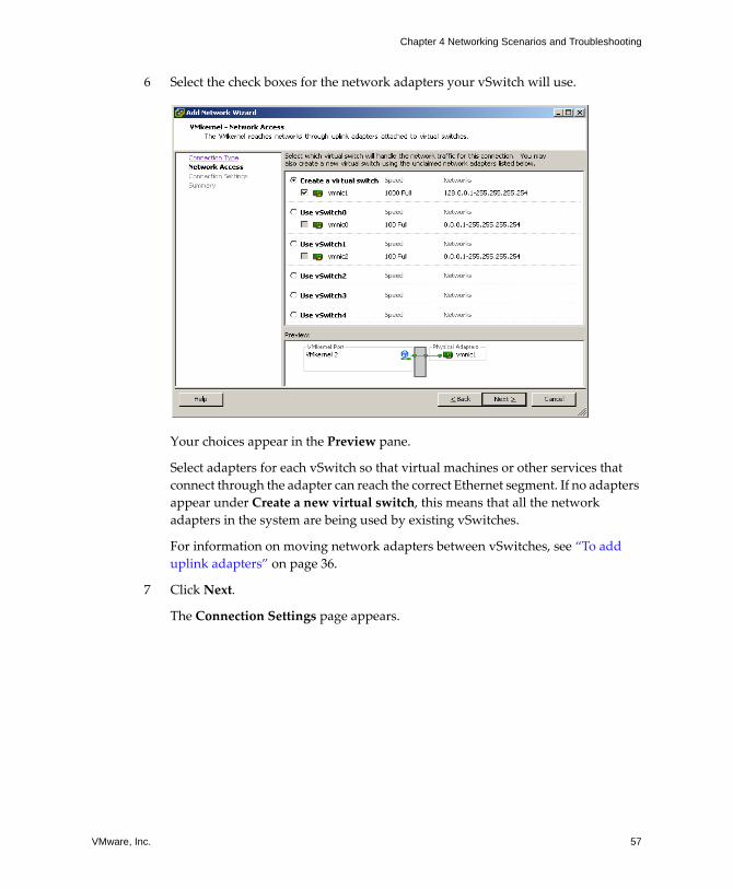
VMware, Inc. 57
Chapter 4 Networking Scenarios and Troubleshooting
6 Select the check boxes for the network adapters your vSwitch will use.
Your choices appear in the Preview pane.
Select adapters for each vSwitch so that virtual machines or other services that connect through the adapter can reach the correct Ethernet segment. If no adapters appear under Create a new virtual switch, this means that all the network adapters in the system are being used by existing vSwitches.
For information on moving network adapters between vSwitches, see �To add uplink adapters� on page 36.
7 Click Next.
The Connection Settings page appears.
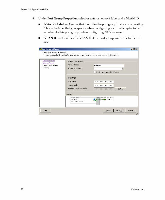
Server Configuration Guide
58 VMware, Inc.
8 Under Port Group Properties, select or enter a network label and a VLAN ID.
! Network Label � A name that identifies the port group that you are creating. This is the label that you specify when configuring a virtual adapter to be attached to this port group, when configuring iSCSI storage.
! VLAN ID � Identifies the VLAN that the port group�s network traffic will use.

VMware, Inc. 59
Chapter 4 Networking Scenarios and Troubleshooting
9 Under IP Settings, click Edit to set the VMkernel Default Gateway for iSCSI.
The DNS and Routing Configuration dialog box appears. Under the DNS Configuration tab, the name of the host is entered into the name field by default. The DNS server addresses that were specified during installation are also preselected as is the domain.
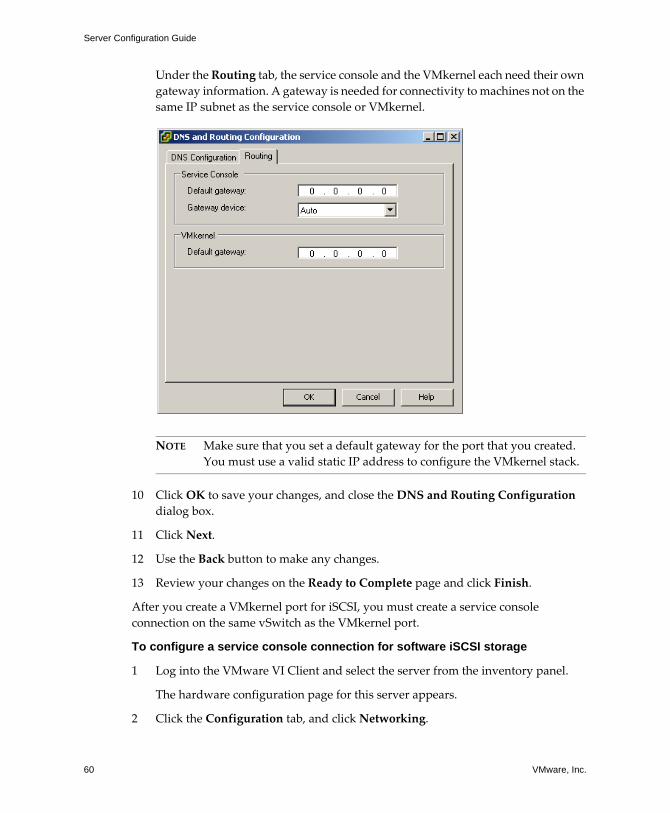
Server Configuration Guide
60 VMware, Inc.
Under the Routing tab, the service console and the VMkernel each need their own gateway information. A gateway is needed for connectivity to machines not on the same IP subnet as the service console or VMkernel.
NOTE Make sure that you set a default gateway for the port that you created. You must use a valid static IP address to configure the VMkernel stack.
10 Click OK to save your changes, and close the DNS and Routing Configuration dialog box.
11 Click Next.
12 Use the Back button to make any changes.
13 Review your changes on the Ready to Complete page and click Finish.
After you create a VMkernel port for iSCSI, you must create a service console connection on the same vSwitch as the VMkernel port.
To configure a service console connection for software iSCSI storage
1 Log into the VMware VI Client and select the server from the inventory panel.
The hardware configuration page for this server appears.
2 Click the Configuration tab, and click Networking.
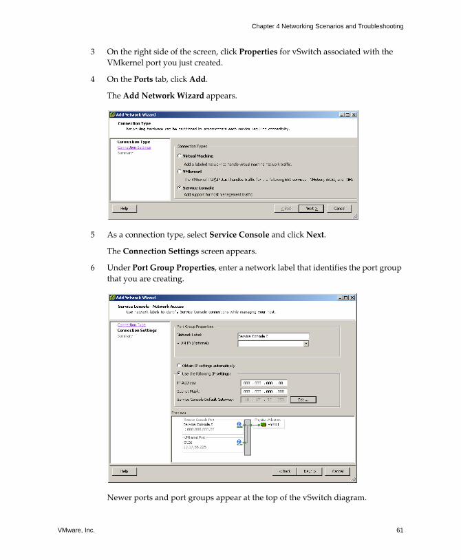
VMware, Inc. 61
Chapter 4 Networking Scenarios and Troubleshooting
3 On the right side of the screen, click Properties for vSwitch associated with the VMkernel port you just created.
4 On the Ports tab, click Add.
The Add Network Wizard appears.
5 As a connection type, select Service Console and click Next.
The Connection Settings screen appears.
6 Under Port Group Properties, enter a network label that identifies the port group that you are creating.
Newer ports and port groups appear at the top of the vSwitch diagram.
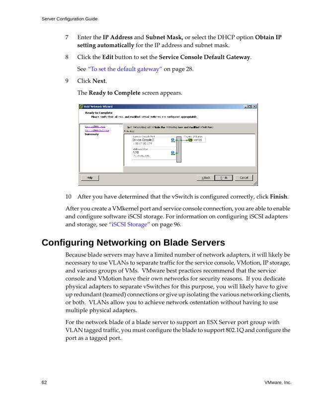
Server Configuration Guide
62 VMware, Inc.
7 Enter the IP Address and Subnet Mask, or select the DHCP option Obtain IP setting automatically for the IP address and subnet mask.
8 Click the Edit button to set the Service Console Default Gateway.
See �To set the default gateway� on page 28.
9 Click Next.
The Ready to Complete screen appears.
10 After you have determined that the vSwitch is configured correctly, click Finish.
After you create a VMkernel port and service console connection, you are able to enable and configure software iSCSI storage. For information on configuring iSCSI adapters and storage, see �iSCSI Storage� on page 96.
Configuring Networking on Blade ServersBecause blade servers may have a limited number of network adapters, it will likely be necessary to use VLANs to separate traffic for the service console, VMotion, IP storage, and various groups of VMs. VMware best practices recommend that the service console and VMotion have their own networks for security reasons. If you dedicate physical adapters to separate vSwitches for this purpose, you will likely have to give up redundant (teamed) connections or give up isolating the various networking clients, or both. VLANs allow you to achieve network ostentation without having to use multiple physical adapters.
For the network blade of a blade server to support an ESX Server port group with VLAN tagged traffic, you must configure the blade to support 802.1Q and configure the port as a tagged port.
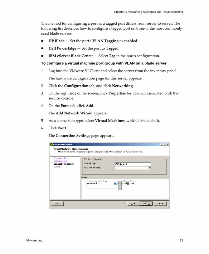
VMware, Inc. 63
Chapter 4 Networking Scenarios and Troubleshooting
The method for configuring a port as a tagged port differs from server to server. The following list describes how to configure a tagged port on three of the most commonly used blade servers:
! HP Blade � Set the port�s VLAN Tagging to enabled.
! Dell PowerEdge � Set the port to Tagged.
! IBM eServer Blade Center � Select Tag in the port�s configuration.
To configure a virtual machine port group with VLAN on a blade server
1 Log into the VMware VI Client and select the server from the inventory panel.
The hardware configuration page for this server appears.
2 Click the Configuration tab, and click Networking.
3 On the right side of the screen, click Properties for vSwitch associated with the service console.
4 On the Ports tab, click Add.
The Add Network Wizard appears.
5 As a connection type, select Virtual Machines, which is the default.
6 Click Next.
The Connection Settings page appears.
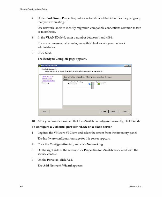
Server Configuration Guide
64 VMware, Inc.
7 Under Port Group Properties, enter a network label that identifies the port group that you are creating.
Use network labels to identify migration‐compatible connections common to two or more hosts.
8 In the VLAN ID field, enter a number between 1 and 4094.
If you are unsure what to enter, leave this blank or ask your network administrator.
9 Click Next.
The Ready to Complete page appears.
10 After you have determined that the vSwitch is configured correctly, click Finish.
To configure a VMkernel port with VLAN on a blade server
1 Log into the VMware VI Client and select the server from the inventory panel.
The hardware configuration page for this server appears.
2 Click the Configuration tab, and click Networking.
3 On the right side of the screen, click Properties for vSwitch associated with the service console.
4 On the Ports tab, click Add.
The Add Network Wizard appears.
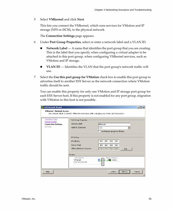
VMware, Inc. 65
Chapter 4 Networking Scenarios and Troubleshooting
5 Select VMkernel and click Next.
This lets you connect the VMkernel, which runs services for VMotion and IP storage (NFS or iSCSI), to the physical network.
The Connection Settings page appears.
6 Under Port Group Properties, select or enter a network label and a VLAN ID.
! Network Label � A name that identifies the port group that you are creating. This is the label that you specify when configuring a virtual adapter to be attached to this port group, when configuring VMkernel services, such as VMotion and IP storage.
! VLAN ID � Identifies the VLAN that the port group�s network traffic will use.
7 Select the Use this port group for VMotion check box to enable this port group to advertise itself to another ESX Server as the network connection where VMotion traffic should be sent.
You can enable this property for only one VMotion and IP storage port group for each ESX Server host. If this property is not enabled for any port group, migration with VMotion to this host is not possible.
Server Configuration Guide
66 VMware, Inc.
8 Under IP Settings, click Edit to set the VMkernel Default Gateway for VMkernel services, such as VMotion, NAS, and iSCSI
NOTE Make sure that you set a default gateway for the port that you created. VirtualCenter 2 behaves differently here from VirtualCenter 1.x. You must use a valid IP address to configure the VMkernel IP stack, not a dummy address.
The DNS and Routing Configuration dialog box appears. Under the DNS Configuration tab, the name of the host is entered into the name field by default. The DNS server addresses that were specified during installation are also preselected as is the domain.
Under the Routing tab, the service console and the VMkernel each need their own gateway information. A gateway is needed if connectivity to machines not on the same IP subnet as the service console or VMkernel.
Static IP settings is the default.
9 Click OK to save your changes, and close the DNS Configuration and Routing dialog box.
10 Click Next.
11 Use the Back button to make any changes.
12 Review your changes on the Ready to Complete page and click Finish.
VMware, Inc. 67
Chapter 4 Networking Scenarios and Troubleshooting
TroubleshootingThe following section guides you through troubleshooting common networking issues.
This section covers the following topics:
! �Troubleshooting Service Console Networking� on page 67
! �Troubleshooting Network Adapter Configuration� on page 68
! �Troubleshooting Physical Switch Configuration� on page 69
! �Troubleshooting Port Group Configuration� on page 69
Troubleshooting Service Console NetworkingIf certain parts of the service console�s networking are misconfigured, you will lose your ability to access your ESX Server host with the VI Client. In the event that this happens, you can reconfigure networking by connecting directly to service console and using the following service console commands:
! esxcfg-vswif -l
Provides a list of the service console�s current network interfaces.
Check that vswif0 is present and that the current IP address and Netmask are correct.
! esxcfg-vswitch -l
Provides a list of current virtual switch configurations.
Check that the uplink adapter configured for the service console is connected to the appropriate physical network.
! exscfg-nics -l
Provides a list of current network adapters.
Check that the uplink adapter configured for the service console is up and that the speed and duplex are both correct.
! esxcfg-nics -s <speed> <nic>
Changes the speed of a network adapter.
! esxcfg-nics -d <duplex> <nic>
Changes the duplex of a network adapter.
Server Configuration Guide
68 VMware, Inc.
! esxcfg-vswif -i <new ip address> vswifX
Changes the service console�s IP address.
! esxcfg-vswif -n <new netmask> vswifX
Changes the service console�s netmask.
! esxcfg-vswitch -U <old vmnic> <service console vswitch>
Removes the uplink for the service console
! esxcfg-vswitch -L <new vmnic> <service console vswitch>
Changes the uplink for the service console.
If you encounter long waits when using esxcfg-* commands, it is possible that DNS is misconfigured. The esxcfg-* commands require that DNS be configured so that localhost name resolution works properly. This requires that the /etc/hosts file contain an entry for the configured IP address and the 127.0.0.1 localhost address.
Troubleshooting Network Adapter ConfigurationAdding a new network adapter, in certain cases, can cause loss of service console connectivity and manageability using the VI Client due to network adapters getting renamed.
If this happens, you must rename the affected network adapters using the service console.
To rename network adapters using the service console
1 Log in directly to your ESX Serverʹs console.
2 Use the command esxcfg-nics -l to see which names have been assigned to your network adapters.
3 Use the command esxcfg-vswitch -l to see which vSwitches, if any, are now associated with device names no longer shown by esxcfg‐nics.
4 Use the command esxcfg-vswitch -U <old vmnic name> <vswitch> to remove any network adapters that have been renamed.
5 Use the command esxcfg-vswitch -L <new vmnic name> <vswitch> to re‐add the network adapters, giving them the correct names.
VMware, Inc. 69
Chapter 4 Networking Scenarios and Troubleshooting
Troubleshooting Physical Switch ConfigurationIn some cases, you might lose vSwitch connectivity when a failover or failback event occurs. This causes the MAC addresses used by virtual machines associated with that vSwitch to appear on a different switch port than they previously did.
To avoid this problem, put your physical switch in portfast or portfast trunk mode.
Troubleshooting Port Group ConfigurationChanging the name of a port group when virtual machines are already connected to that port group causes the virtual machines configured to connect to that port group to have invalid network configuration.
The connection from virtual network adapters to port groups is made by name, and the name is what is stored in the virtual machine configuration. Changing the name of a port group does not cause a mass reconfiguration of all the virtual machines connected to that port group. Virtual machines that are already powered on will continue to function until they are powered off because their connections to the network have already been established.
The best principle is to avoid renaming networks after they are in use. After you rename a port group, you must re‐configure each associated virtual machine using the service console to reflect the new port group name.

Server Configuration Guide
70 VMware, Inc.
VMware, Inc. 71
Storage

Server Configuration Guide
72 VMware, Inc.
VMware, Inc. 73
CHAPTER 5 Introduction to Storage
This chapter contains overview information about the available storage options for ESX Server.
For information about configuring SANs, see the SAN Configuration Guide. For information about configuring virtual machines, see the Virtual Machine Management Guide.
This chapter covers the following topics:
! �Storage Concepts� on page 74
! �Storage Overview� on page 75
! �Viewing Storage Information in the Virtual Infrastructure Client� on page 79
! �VMware File System� on page 82
! �Configuring and Managing Storage� on page 86
Server Configuration Guide
74 VMware, Inc.
Storage ConceptsA few concepts are essential for a thorough understanding of storage.
! Datastore � Formatted logical container analogous to a file system on a logical volume. The datastore holds virtual machine files and can exist on different types of physical storage including SCSI, iSCSI, Fibre Channel SAN, or NFS. Datastores can be of the two types: VMFS‐based or NFS‐based.
! Disk partition � Reserved part of hard disk that is set aside for specific purposes. In the context of ESX Server storage, disk partitions on various physical storage devices can be reserved and formatted as datastores.
! Extent � In the ESX Server context, an extent is a hard disk partition on a physical storage device that can be dynamically added to an existing VMFS‐based datastore. The datastore can stretch over multiple extents, yet appear as a single volume analogous to a spanned volume.
! Failover path � Redundant physical path that the ESX Server system can use when communicating with its networked storage. The ESX Server system uses the failover path if any component responsible for transferring storage data fails. See Multipathing.
! Fibre Channel (FC) � High‐speed data transmitting technology that ESX Server systems use to transport SCSI traffic from virtual machines to storage devices on a SAN. The Fibre Channel Protocol (FCP) packages SCSI commands into Fibre Channel frames.
! iSCSI (Internet SCSI) � Packages SCSI storage traffic into TCP so it can travel through IP networks instead of the specialized FC network. With iSCSI connection, your ESX Server system (initiator) communicates with a remote storage device (target) as it would do with a local hard disk.
! LUN (logical unit number) � Address uniquely identifying each SCSI disk that an ESX Server system uses for storage. The terms hard disk and LUN are often used interchangeably.
! Multipathing � Technique that lets you use more than one physical path, or an element on this path, responsible for transferring data between the ESX Server system and its remote storage. This redundant use of physical paths or elements, such as adapters, helps ensure uninterrupted traffic between the ESX Server system and storage devices.
! NAS (network‐attached storage) � Specialized storage device that connects to a network and can provide file access services to ESX Server systems. ESX Server systems use the NFS protocol to communicate with NAS servers.
VMware, Inc. 75
Chapter 5 Introduction to Storage
! NFS (network file system) � File sharing protocol ESX Server supports to communicate with a NAS device.
! Raw device � Disk used directly by a virtual machine.
! Raw device mapping (RDM) � Special file in a VMFS volume that acts as a proxy for a raw device and maps SAN LUNs directly to a virtual machine.
! Spanned volume � Dynamic volume that uses disk space on more than one physical disk, yet appears as a single logical volume.
! Storage device � Physical disk or storage array that can either be internal or located outside of your system and connected to the system either directly or through an adapter.
! VMFS (VMware File System) � High‐performance cluster file system that provides storage virtualization optimized for virtual machines.
! Volume � Logical storage unit, which can use disk space on one physical device, or its part, or span several physical devices.
Storage OverviewIn the most common configuration, a virtual machine uses a virtual hard disk to store its operating system, program files, and other data associated with its activities. A virtual disk is a large physical file that can be copied, moved, archived, and backed up as easy as any other file.
Virtual disk files reside on specially formatted volumes called datastores. A datastore can be deployed on the host machine�s internal direct‐attached storage devices or on networked storage devices. A networked storage device represents an external shared storage device or array that is located outside of your system and is typically accessed over a network through an adapter.
Storing virtual disks and other essential pieces of your virtual machine on a single datastore shared between physical hosts lets you:
! Use such features as VMware DRS (Distributed Resource Scheduling) and VMware HA (High Availability Options).
! Use VMotion to move running virtual machines from one ESX Server to another without service interruption.
! Use Consolidated Backup to perform backups more efficiently.
! Have better protection from planned or unplanned server outages.
! Have more control over load balancing.
Server Configuration Guide
76 VMware, Inc.
ESX Server lets you access a variety of physical storage devices, both internal and external, configure and format them, and use them for your storage needs.
Most of the time, you will be using VI Client to work with your storage. The following chapters teach you how to access and configure your storage devices, as well as how to deploy and manage datastores:
! �Configuring Storage� on page 89
! �Managing Storage� on page 125
Datastores and File SystemsESX Server virtual machines store their virtual disk files on specially formatted logical containers, or datastores, that can exist on different types of physical storage devices. A datastore can use disk space on one physical device or several physical devices.
Your datastore management process starts with storage space that your storage administrator preallocates for your ESX Server system on different storage devices. The storage space is presented to your ESX Server system as LUNs (logical unit numbers) or, in case of a network attached storage, as NFS volumes.
Using the VI Client, you can create datastores by accessing and formatting available LUNs or by mounting the NFS volumes.
After you create the datastores, you can use them to store virtual machine files. When needed, you can modify the datastores. For example, you can add extents to your datastore, rename, or remove it.
For information on managing datastores, see �Managing Datastores and File Systems� on page 126.
File System FormatsDatastores that you use can have the following file system formats:
! VMFS � ESX Server deploys this type of file system on local SCSI disks, iSCSI LUNs, or Fibre Channel LUNs, creating one directory for each virtual machine. VMFS is a clustered file system that can be accessed simultaneously by multiple ESX Server systems.
NOTE ESX Server 3.0 supports VMFS version 3 (VMFS‐3). VMFS‐3 is not backward compatible with versions of ESX Server earlier than ESX Server 3.0. If you are using VMFS‐2, you need to upgrade it to VMFS‐3. For information on upgrading your VMFS‐2, see �Upgrading Datastores� on page 127.
VMware, Inc. 77
Chapter 5 Introduction to Storage
For more information on VMFS, see �VMware File System� on page 82.
As an alternative to using the VMFS‐based datastore, your virtual machine can have direct access to raw devices using a Raw Device Mapping (RDM) as a proxy. For more information on Raw Device Mapping, see �Raw Device Mapping� on page 141.
! NFS � ESX Server can use a designated NFS volume located on an NFS server. ESX Server mounts the NFS volume creating one directory for each virtual machine. From the viewpoint of the user on a client computer, the mounted files are indistinguishable from local files.
Types of StorageDatastores can reside on a variety of storage devices. You can deploy a datastore on your system�s direct‐attached storage device or on a networked storage device.
ESX Server supports the following types of storage devices:
! Local � Stores files locally on an internal or external SCSI device.
! Fibre Channel � Stores files remotely on a Storage Area Network (SAN). Requires Fibre Channel adapters.
! iSCSI (hardware initiated) � Stores files on remote iSCSI storage devices. Files are accessed over TCP/IP network using hardware‐based iSCSI HBAs (host bus adapters).
! iSCSI (software initiated) � Stores files on remote iSCSI storage devices. Files are accessed over TCP/IP network using software‐based iSCSI code in the VMkernel. Requires a standard network adapter for network connectivity.
! Network file system (NFS) � Stores files on remote file servers. Files are accessed over TCP/IP network using the NFS protocol. Requires a standard network adapter for network connectivity.
NOTE ESX Server doesn�t currently support storing virtual machine files on SAS, SATA, IDE, or EIDE drives.
You use the VI Client to access storage devices mapped to your ESX Server system and deploy datastores on them. For more information, refer to �Configuring Storage� on page 89.
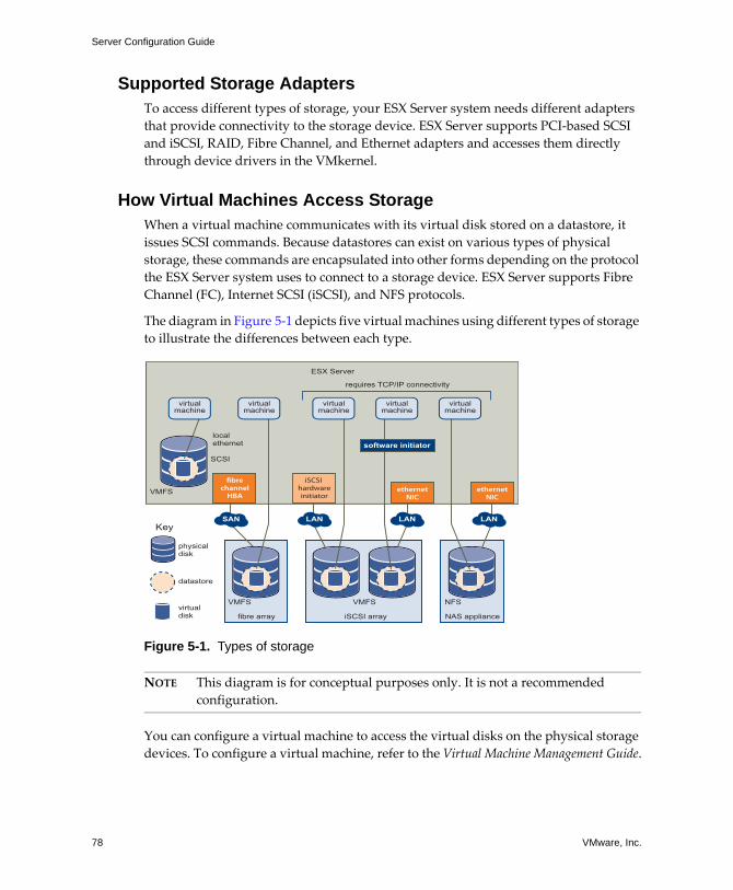
Server Configuration Guide
78 VMware, Inc.
Supported Storage AdaptersTo access different types of storage, your ESX Server system needs different adapters that provide connectivity to the storage device. ESX Server supports PCI‐based SCSI and iSCSI, RAID, Fibre Channel, and Ethernet adapters and accesses them directly through device drivers in the VMkernel.
How Virtual Machines Access StorageWhen a virtual machine communicates with its virtual disk stored on a datastore, it issues SCSI commands. Because datastores can exist on various types of physical storage, these commands are encapsulated into other forms depending on the protocol the ESX Server system uses to connect to a storage device. ESX Server supports Fibre Channel (FC), Internet SCSI (iSCSI), and NFS protocols.
The diagram in Figure 5‐1 depicts five virtual machines using different types of storage to illustrate the differences between each type.
Figure 5-1. Types of storage
NOTE This diagram is for conceptual purposes only. It is not a recommended configuration.
You can configure a virtual machine to access the virtual disks on the physical storage devices. To configure a virtual machine, refer to the Virtual Machine Management Guide.
iSCSI array NAS appliancefibre array
ESX Server
VMFS
localethernet
SCSI
VMFS VMFS NFS
virtualmachine
virtualmachine
virtualmachine
virtualmachine
virtualmachine
SAN LAN LAN LAN
iSCSI hardwareinitiator
fibrechannelHBA
ethernetNIC
ethernetNIC
software initiator
requires TCP/IP connectivity
Key
physicaldisk
datastore
virtualdisk
VMware, Inc. 79
Chapter 5 Introduction to Storage
Viewing Storage Information in the Virtual Infrastructure Client
The VI Client displays detailed information on available datastores, storage devices the datastores use, and configured adapters. See these sections for more information:
! �Displaying Datastores� on page 79
! �Viewing Storage Adapters� on page 80
Displaying DatastoresDatastores are added to the VI Client in one of two ways:
! Discovered when a host is added to the inventory � When you add a host to the inventory, the VI Client displays any datastores recognized by the host.
! Created on an available storage device � You can use the Add Storage command to create and configure a new datastore. For more information, see �Configuring Storage� on page 89.
You can view a list of available datastores and analyze their properties.
To display datastores, on the host Configuration tab, click the Storage (SCSI, SAN, and NFS) link.
For each datastore, the Storage section shows summary information, including:
! Target storage device where the datastore is located. See �Understanding Storage Device Naming in the Display� on page 81.
! Type of file system the datastore uses. See �File System Formats� on page 76.
! Total capacity, including the used and available space.
To view additional details about the specific datastore, select the datastore from the list. The Details section shows the following information:
! Location of the datastore.
! Individual extents the datastore spans and their capacity.
! Paths used to access the storage device.
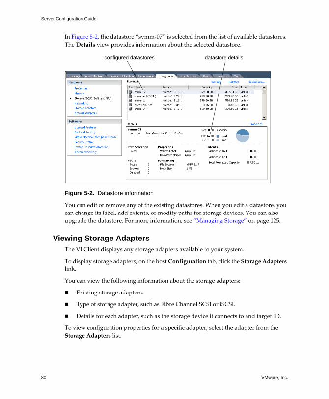
Server Configuration Guide
80 VMware, Inc.
In Figure 5‐2, the datastore �symm‐07� is selected from the list of available datastores. The Details view provides information about the selected datastore.
Figure 5-2. Datastore information
You can edit or remove any of the existing datastores. When you edit a datastore, you can change its label, add extents, or modify paths for storage devices. You can also upgrade the datastore. For more information, see �Managing Storage� on page 125.
Viewing Storage AdaptersThe VI Client displays any storage adapters available to your system.
To display storage adapters, on the host Configuration tab, click the Storage Adapters link.
You can view the following information about the storage adapters:
! Existing storage adapters.
! Type of storage adapter, such as Fibre Channel SCSI or iSCSI.
! Details for each adapter, such as the storage device it connects to and target ID.
To view configuration properties for a specific adapter, select the adapter from the Storage Adapters list.
configured datastores datastore details
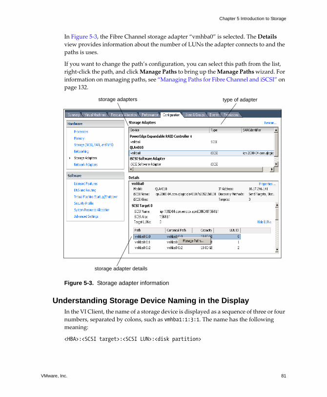
VMware, Inc. 81
Chapter 5 Introduction to Storage
In Figure 5‐3, the Fibre Channel storage adapter �vmhba0� is selected. The Details view provides information about the number of LUNs the adapter connects to and the paths is uses.
If you want to change the path�s configuration, you can select this path from the list, right‐click the path, and click Manage Paths to bring up the Manage Paths wizard. For information on managing paths, see �Managing Paths for Fibre Channel and iSCSI� on page 132.
Figure 5-3. Storage adapter information
Understanding Storage Device Naming in the DisplayIn the VI Client, the name of a storage device is displayed as a sequence of three or four numbers, separated by colons, such as vmhba1:1:3:1. The name has the following meaning:
<HBA>:<SCSI target>:<SCSI LUN>:<disk partition>
storage adapters type of adapter
storage adapter details
Server Configuration Guide
82 VMware, Inc.
The abbreviation vmhba refers to different physical HBAs on the ESX Server system. It can also refer to the virtual iSCSI initiator that ESX Server implements using the VMkernel network stack. The forth number indicates a partition on a disk or LUN. When a datastore occupies the entire disk or LUN, the forth number isn�t present.
The vmhba1:1:3:1 example refers to the first partition on SCSI LUN3, SCSI target 1, which is accessed through HBA 1.
While the third and the forth numbers never change, the first two numbers can change. For example, after rebooting the ESX Server system, vmhba1:1:3:1 can change to vmhba3:2:3:1, however, the name still refers to the same physical device. The first and the second numbers can change for the following reasons:
! The first number, the HBA, changes when an outage on the Fibre Channel or iSCSI network occurs. In this case, the ESX Server system has to use a different HBA to access the storage device.
! The second number, the SCSI target, changes in case of any modifications in the mappings of the Fibre Channel or iSCSI targets visible to the ESX Server host.
VMware File SystemA file system is a method for storing, organizing, accessing, navigating, and retrieving computer files and the data they contain. File systems come in different formats, including FAT, NTFS, HPFS, UFS, and EXT3. VMware offers a special high‐performance file system, VMware file system (VMFS), optimized for storing ESX Server virtual machines.
VMFS VersionsESX Server offers the following versions of this file system:
! VMFS2 � This file system is created with ESX Server version 2.x.
! VMFS3 � This file system is created with ESX Server version 3. VMFS3 enhancements include multi‐directory support. A virtual machine must reside on a VMFS3 file system before an ESX Server version 3 host can power it on.
Table 5-1. Host Access to VMFS File Systems
Host VMFS2 Datastore VMFS3 DatastoreESX Server version2 host Read/Write (Runs VMs) No access
ESX Server version3 host Read Only (Copies VMs) Read/Write (Runs VMs)
VMware, Inc. 83
Chapter 5 Introduction to Storage
Creating and Growing VMFSVMFS can be deployed on a variety of SCSI‐based storage devices, including Fibre Channel and iSCSI SAN equipment. A virtual disk stored on VMFS always appears to the virtual machine as a mounted SCSI device. The virtual disk hides a physical storage layer from the virtual machine�s operating system. This allows you to run even operating systems not certified for SAN inside the virtual machine.
For the operating system inside the virtual machine, VMFS preserves the internal file system semantics, which ensures correct application behavior and data integrity for applications running in virtual machines.
You can set up VMFS‐based datastores in advance on any storage device that your ESX Server discovers. Select a large LUN if you plan to create multiple virtual machines on it. You can then add virtual machines dynamically without having to request additional disk space.
However, if more space is needed, you can increase the VMFS volume at any time�up to 64 TB.
Considerations when Creating VMFSYou need to plan how to set up storage for your ESX Server systems before you format storage devices with VMFS. You should always have only one VMFS volume per LUN. You can, however, decide to use one large VMFS volume or multiple smaller VMFS volumes. ESX Server lets you have up to 256 VMFS volumes per system with the minimum volume size 1.2 GB.
You might want fewer, larger VMFS volumes for the following reasons:
! More flexibility to create virtual machines without going back to the storage administrator for more space.
! More flexibility for resizing virtual disks, doing snapshots, and so on.
! Fewer VMFS‐based datastores to manage.
You might want more, smaller VMFS volumes for the following reasons:
! Less contention on each VMFS due to locking and SCSI reservation issues.
! Less wasted storage space.
! Different applications might need different RAID characteristics.
Server Configuration Guide
84 VMware, Inc.
! More flexibility, as the multipathing policy and disk shares are set per LUN.
! Use of Microsoft Cluster Service requires that each cluster disk resource is in its own LUN.
You might decide to configure some of your servers to use fewer, larger VMFS volumes and other servers to use more, smaller VMFS volumes.
VMFS Sharing CapabilitiesYou can store multiple virtual machines on a single VMFS volume and let multiple ESX Servers to access this volume.
Storing Multiple Virtual Machines on a VMFS VolumeYou can store multiple virtual machines on the same VMFS volume. Each virtual machine, encapsulated in a small set of files, occupies a separate single directory. VMFS supports the following file and block sizes enabling you to run even the most data intensive applications, including databases, ERP, and CRM in virtual machines:
! Maximum virtual disk size: 2 TB
! Maximum file size: 2 TB
! Block size: 1 MB to 8 MB
When planning to store multiple virtual machines on the same VMFS volume, keep in mind that the more virtual machines are sharing the same volume, the greater is the potential for performance degradation due to I/O contention.
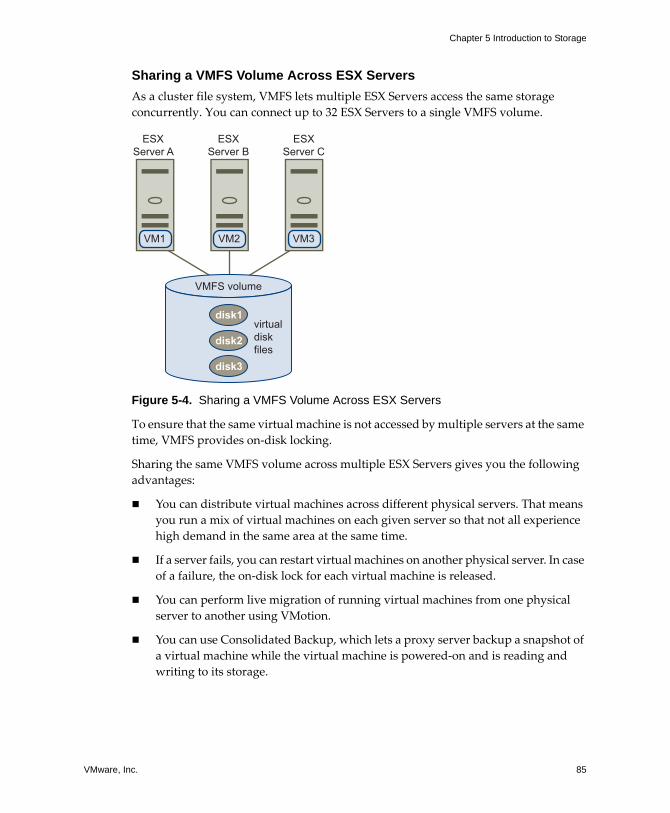
VMware, Inc. 85
Chapter 5 Introduction to Storage
Sharing a VMFS Volume Across ESX ServersAs a cluster file system, VMFS lets multiple ESX Servers access the same storage concurrently. You can connect up to 32 ESX Servers to a single VMFS volume.
Figure 5-4. Sharing a VMFS Volume Across ESX Servers
To ensure that the same virtual machine is not accessed by multiple servers at the same time, VMFS provides on‐disk locking.
Sharing the same VMFS volume across multiple ESX Servers gives you the following advantages:
! You can distribute virtual machines across different physical servers. That means you run a mix of virtual machines on each given server so that not all experience high demand in the same area at the same time.
! If a server fails, you can restart virtual machines on another physical server. In case of a failure, the on‐disk lock for each virtual machine is released.
! You can perform live migration of running virtual machines from one physical server to another using VMotion.
! You can use Consolidated Backup, which lets a proxy server backup a snapshot of a virtual machine while the virtual machine is powered‐on and is reading and writing to its storage.
VMFS volume
ESXServer A
ESXServer B
ESXServer C
virtualdiskfiles
VM1 VM2 VM3
disk1
disk2
disk3
Server Configuration Guide
86 VMware, Inc.
Configuring and Managing StorageThe Storage section of this guide covers most of the general concepts and outlines tasks you need to perform when working with storage.
Configuring Storage on ESX Server HostsFor detailed information on configuring and formatting storage, refer to �Configuring Storage� on page 89.
For detailed information on configuring SANs, refer to the SAN Configuration Guide.
Storage Configuration and Management TasksThe storage tasks you can perform in ESX Server are listed in the following sections.
Local SCSI Configuration Tasks�To create a datastore on a local SCSI disk� on page 91
Fibre Channel Tasks�To create a datastore on a Fibre Channel device� on page 94
Hardware-Initiated iSCSI Tasks! �To view the iSCSI hardware initiator properties� on page 101
! �To set up the iSCSI name and IP address for the hardware initiator� on page 103
! �To set up target discovery addresses for the hardware initiator� on page 104
! �To set up CHAP parameters for the hardware initiator� on page 106
! �To create a datastore on a hardware‐initiated iSCSI device� on page 107
Software-Initiated iSCSI Tasks! �To view the iSCSI software initiator properties� on page 110
! �To enable the iSCSI software initiator� on page 112
! �To set up target discovery addresses for the software initiator� on page 113
! �To set up CHAP parameters for the software initiator� on page 114
! �To create a datastore on a software‐initiated iSCSI device� on page 116
NFS Tasks�To mount an NFS volume� on page 122

VMware, Inc. 87
Chapter 5 Introduction to Storage
General Storage Tasks! �To upgrade the VMFS‐2 to VMFS‐3� on page 128
! �To edit the name of the datastore� on page 129
! �To add one or more extents to the datastore� on page 130
! �To remove a datastore� on page 127
Path Managing Tasks! �To set the multipathing policy� on page 136
! �To disable a path� on page 137
! �To set the preferred path� on page 138

Server Configuration Guide
88 VMware, Inc.
VMware, Inc. 89
CHAPTER 6 Configuring Storage
This chapter contains information about configuring local SCSI disks, Fibre Channel Storage Area Network (SAN) storage, iSCSI, and NFS volumes.
NOTE For additional information about configuring SANs, see the SAN Configuration Guide.
This chapter covers the following topics:
! �Local SCSI Disk Storage� on page 90
! �Fibre Channel Storage� on page 93
! �iSCSI Storage� on page 96
! �Network Attached Storage� on page 119
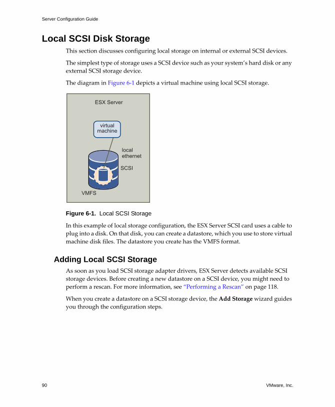
Server Configuration Guide
90 VMware, Inc.
Local SCSI Disk StorageThis section discusses configuring local storage on internal or external SCSI devices.
The simplest type of storage uses a SCSI device such as your system�s hard disk or any external SCSI storage device.
The diagram in Figure 6‐1 depicts a virtual machine using local SCSI storage.
Figure 6-1. Local SCSI Storage
In this example of local storage configuration, the ESX Server SCSI card uses a cable to plug into a disk. On that disk, you can create a datastore, which you use to store virtual machine disk files. The datastore you create has the VMFS format.
Adding Local SCSI StorageAs soon as you load SCSI storage adapter drivers, ESX Server detects available SCSI storage devices. Before creating a new datastore on a SCSI device, you might need to perform a rescan. For more information, see �Performing a Rescan� on page 118.
When you create a datastore on a SCSI storage device, the Add Storage wizard guides you through the configuration steps.
ESX Server
VMFS
localethernet
SCSI
virtualmachine
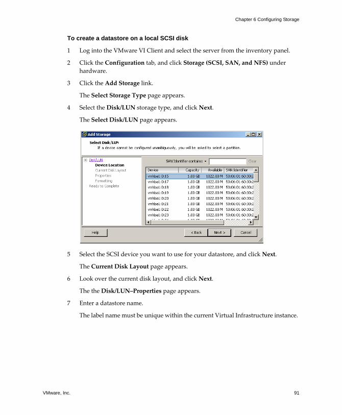
VMware, Inc. 91
Chapter 6 Configuring Storage
To create a datastore on a local SCSI disk
1 Log into the VMware VI Client and select the server from the inventory panel.
2 Click the Configuration tab, and click Storage (SCSI, SAN, and NFS) under hardware.
3 Click the Add Storage link.
The Select Storage Type page appears.
4 Select the Disk/LUN storage type, and click Next.
The Select Disk/LUN page appears.
5 Select the SCSI device you want to use for your datastore, and click Next.
The Current Disk Layout page appears.
6 Look over the current disk layout, and click Next.
The the Disk/LUN�Properties page appears.
7 Enter a datastore name.
The label name must be unique within the current Virtual Infrastructure instance.
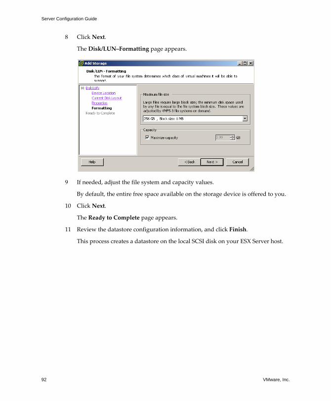
Server Configuration Guide
92 VMware, Inc.
8 Click Next.
The Disk/LUN�Formatting page appears.
9 If needed, adjust the file system and capacity values.
By default, the entire free space available on the storage device is offered to you.
10 Click Next.
The Ready to Complete page appears.
11 Review the datastore configuration information, and click Finish.
This process creates a datastore on the local SCSI disk on your ESX Server host.
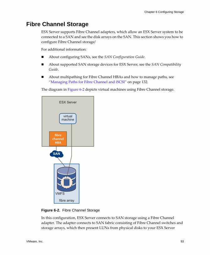
VMware, Inc. 93
Chapter 6 Configuring Storage
Fibre Channel StorageESX Server supports Fibre Channel adapters, which allow an ESX Server system to be connected to a SAN and see the disk arrays on the SAN. This section shows you how to configure Fibre Channel storage/
For additional information:
! About configuring SANs, see the SAN Configuration Guide.
! About supported SAN storage devices for ESX Server, see the SAN Compatibility Guide.
! About multipathing for Fibre Channel HBAs and how to manage paths, see �Managing Paths for Fibre Channel and iSCSI� on page 132.
The diagram in Figure 6‐2 depicts virtual machines using Fibre Channel storage.
Figure 6-2. Fibre Channel Storage
In this configuration, ESX Server connects to SAN storage using a Fibre Channel adapter. The adapter connects to SAN fabric consisting of Fibre Channel switches and storage arrays, which then present LUNs from physical disks to your ESX Server
fibre array
VMFS
virtualmachine
SAN
fibrechannelHBA
ESX Server
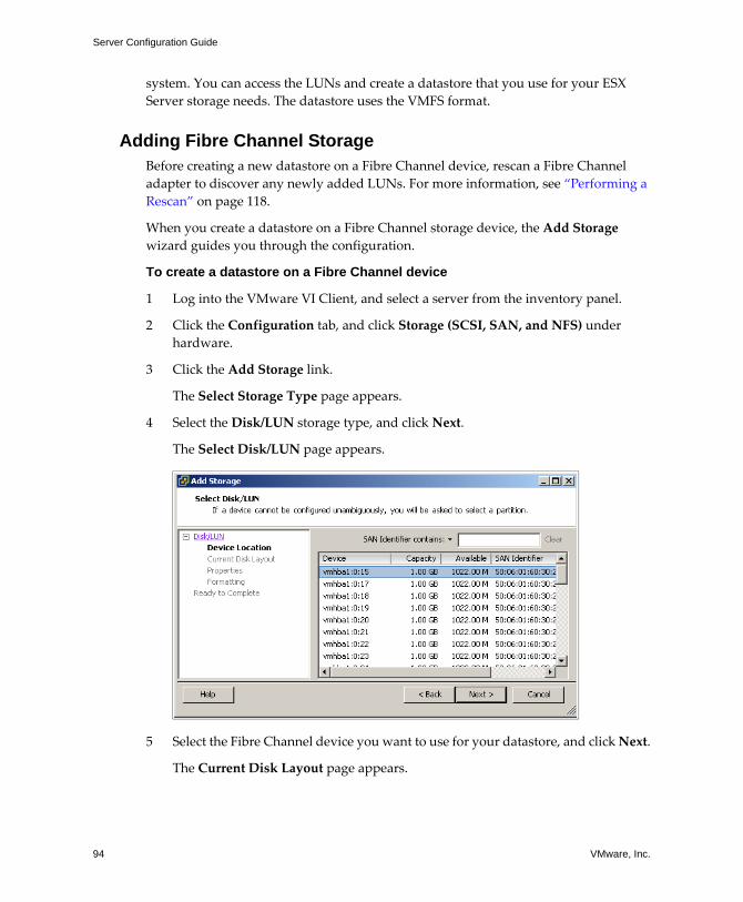
Server Configuration Guide
94 VMware, Inc.
system. You can access the LUNs and create a datastore that you use for your ESX Server storage needs. The datastore uses the VMFS format.
Adding Fibre Channel StorageBefore creating a new datastore on a Fibre Channel device, rescan a Fibre Channel adapter to discover any newly added LUNs. For more information, see �Performing a Rescan� on page 118.
When you create a datastore on a Fibre Channel storage device, the Add Storage wizard guides you through the configuration.
To create a datastore on a Fibre Channel device
1 Log into the VMware VI Client, and select a server from the inventory panel.
2 Click the Configuration tab, and click Storage (SCSI, SAN, and NFS) under hardware.
3 Click the Add Storage link.
The Select Storage Type page appears.
4 Select the Disk/LUN storage type, and click Next.
The Select Disk/LUN page appears.
5 Select the Fibre Channel device you want to use for your datastore, and click Next.
The Current Disk Layout page appears.
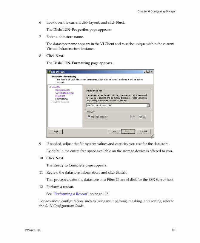
VMware, Inc. 95
Chapter 6 Configuring Storage
6 Look over the current disk layout, and click Next.
The Disk/LUN�Properties page appears.
7 Enter a datastore name.
The datastore name appears in the VI Client and must be unique within the current Virtual Infrastructure instance.
8 Click Next.
The Disk/LUN�Formatting page appears.
9 If needed, adjust the file system values and capacity you use for the datastore.
By default, the entire free space available on the storage device is offered to you.
10 Click Next.
The Ready to Complete page appears.
11 Review the datastore information, and click Finish.
This process creates the datastore on a Fibre Channel disk for the ESX Server host.
12 Perform a rescan.
See �Performing a Rescan� on page 118.
For advanced configuration, such as using multipathing, masking, and zoning, refer to the SAN Configuration Guide.
Server Configuration Guide
96 VMware, Inc.
iSCSI StorageThis section discusses configuring iSCSI storage and provides the following information:
! �About iSCSI Storage� on page 96
! �Configuring Hardware‐Initiated iSCSI Storage� on page 100
! �Configuring Software‐Initiated iSCSI Storage� on page 109
! �Performing a Rescan� on page 118
For information on multipathing, see �Managing Paths for Fibre Channel and iSCSI� on page 132.
About iSCSI StorageESX Server 3.0 supports iSCSI technology that allows your ESX Server system to use IP network while accessing remote storage. With iSCSI, SCSI storage commands that your virtual machine issues to its virtual disk are converted into TCP/IP protocol packets and transmitted to a remote device, or target, that stores the virtual disk. From the point of view of the virtual machine, the device appears as locally attached SCSI drive.
iSCSI InitiatorsTo access remote targets, your ESX Server host uses iSCSI initiators. Initiators transport SCSI requests and responses between the ESX Server system and the target storage device on the IP network.
ESX Server supports hardware‐based and software‐based iSCSI initiators:
! Hardware iSCSI initiator � A third‐party host bus adapter (HBA) with the iSCSI over TCP/IP capability. This specialized iSCSI adapter is responsible for all iSCSI processing and management. Currently, ESX Server supports only QLogic QLA4010 iSCSI HBA.
! Software iSCSI initiator � A code built into VMkernel that lets your ESX Server system to connect to the iSCSI storage device through standard network adapters. The software initiator handles the iSCSI processing while communicating with the network adapter through the network stack. With the software initiator, you can use the iSCSI technology without purchasing specialized hardware.
NOTE Guest operating systems in virtual machines cannot see iSCSI storage directly. To the guest operating systems, iSCSI storage attached to the ESX Server system appears to be available through a SCSI HBA.
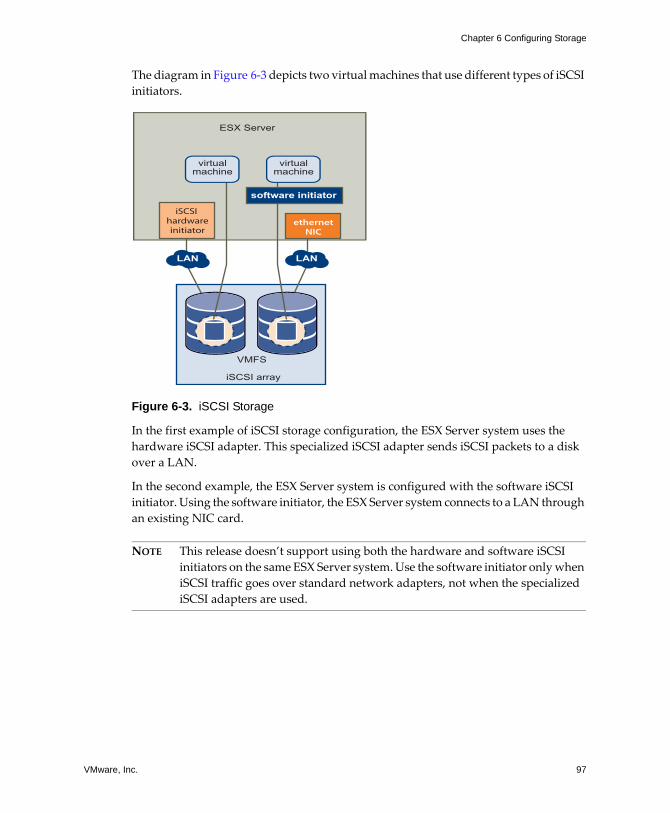
VMware, Inc. 97
Chapter 6 Configuring Storage
The diagram in Figure 6‐3 depicts two virtual machines that use different types of iSCSI initiators.
Figure 6-3. iSCSI Storage
In the first example of iSCSI storage configuration, the ESX Server system uses the hardware iSCSI adapter. This specialized iSCSI adapter sends iSCSI packets to a disk over a LAN.
In the second example, the ESX Server system is configured with the software iSCSI initiator. Using the software initiator, the ESX Server system connects to a LAN through an existing NIC card.
NOTE This release doesn�t support using both the hardware and software iSCSI initiators on the same ESX Server system. Use the software initiator only when iSCSI traffic goes over standard network adapters, not when the specialized iSCSI adapters are used.
iSCSI array
VMFS
virtualmachine
virtualmachine
LAN LAN
iSCSI hardwareinitiator
ethernetNIC
software initiator
ESX Server
Server Configuration Guide
98 VMware, Inc.
Naming RequirementsBecause storage area networks can become large and complex, all iSCSI initiators and targets that use the network have unique and permanent iSCSI names and are assigned addresses for access. The iSCSI name provides a correct identification of a particular iSCSI device, an initiator or a target, regardless of its physical location.
When configuring your iSCSI initiators, make sure they have properly formatted names. The initiators can use one of the following formats:
! IQN (iSCSI qualified name) � Can be up to 255 characters long and has the following format:
iqn.<year-mo>.<reversed_domain_name>:<unique_name>,
where <year-mo> represents the year and month your domain name was registered, <reversed_domain_name> is the official domain name, reversed, and <unique_name> is any name you want to use, for example, the name of your server.
An example might be iqn.1998-01.com.mycompany:myserver.
! EUI (extended unique identifier) � Represents the eui. prefix followed by the 16‐character name. The name includes 24 bits for company name assigned by the IEEE and 40 bits for a unique ID such as a serial number.
Discovery MethodsTo determine which storage resource on the network is available for access, the iSCSI initiators ESX Server system uses these discovery methods:
! Dynamic Discovery � The initiator discovers iSCSI targets by sending a SendTargets request to a specified target address. To use this method, enter the address of the target device so that the initiator can establish a discovery session with this target. The target device responds by forwarding a list of additional targets that the initiator is allowed to access.
! Static Discovery � After the target device used in the SendTargets session sends you the list of available targets, they appear on the Static Discovery list. To this list, you can manually add any additional targets, or remove targets you don�t need.
The static discovery method is available only with the hardware‐initiated storage.
VMware, Inc. 99
Chapter 6 Configuring Storage
iSCSI SecurityBecause iSCSI technology uses the IP networks to connect to remote targets, it is necessary to ensure security of the connection. The IP protocol itself doesn�t protect the data it transports, and it doesn�t have the capability to verify the legitimacy of initiators that access targets on the network. You need to take specific measures to guarantee security across IP networks.
ESX Server supports the Challenge Handshake Authentication Protocol (CHAP) that your iSCSI initiators can use for authentication purposes. After your initiator establishes the initial connection with the target, CHAP verifies the identity of the initiator and checks a CHAP secret that your initiator and the target share. This can be repeated periodically during the iSCSI session.
When configuring iSCSI initiators for your ESX Server system, make sure that CHAP is enabled. For more information, see �Securing iSCSI Storage� on page 197.
Using Fast Retransmit and RecoverySome iSCSI storage arrays implement the fast retransmit and recovery (FRR) algorithm, a TCP/IP enhancement that reduces the time a sender waits before retransmitting a lost data packet. However, other iSCSI storage arrays do not support FRR.
! Without FRR, after transmitting a data packet, the TCP sender sets up a timer for the sent packet. If the packet arrives correctly, the sender receives an acknowledgment for the sent data packet before the timer expires. If the sender doesn�t receive the acknowledgment within the specified time frame, the sender assumes the packet was lost in the network, and retransmits the packet.
! With FRR, if a target receives data packets out of order, for example 1 2 3 ... 5, it immediately sends a notification to the sender indicating that a particular packet (4 in this example) is missing. After receiving the notification, the sender can retransmit the lost packet without waiting for the timer to expire. Because no time is lost for retransmission to begin, FRR makes it possible to recover lost data packets very quickly.
If your ESX Server uses the iSCSI storage array that doesn�t support FRR, you might notice considerable increase in time required to perform certain operations, especially those that involve copying large amounts of data, such as importing, exporting, suspending, and restarting virtual machines.
If the retransmission timer on the iSCSI storage array side is adjustable, you can solve this performance problem by setting the timer to its lowest possible value.
Server Configuration Guide
100 VMware, Inc.
Configuring Hardware-Initiated iSCSI StorageWith hardware‐based iSCSI storage, you use a specialized third‐party adapter capable of accessing iSCSI storage over TCP/IP. This iSCSI adapter handles all iSCSI processing and management for your ESX Server system.
Install and configure the iSCSI hardware adapter before setting up the datastore that resides on an iSCSI storage device.
Use the following instructions when preparing and setting up datastores that you access through the iSCSI hardware connection:
! �Installing iSCSI Hardware Initiator� on page 100
! �Viewing iSCSI Hardware Initiator� on page 101
! �Configuring iSCSI hardware initiator� on page 102
! �Adding Hardware‐Initiated iSCSI Storage� on page 107
Installing iSCSI Hardware InitiatorESX Server 3.0 requires that your host system uses the QLogic QLA4010 iSCSI HBA to initiate iSCSI transactions.
For more information, see the I/O Compatibility Guide for ESX Server on the VMware Web site at www.vmware.com.
For information on obtaining and installing the adapter, see the QLogic web site at www.qlogic.com.
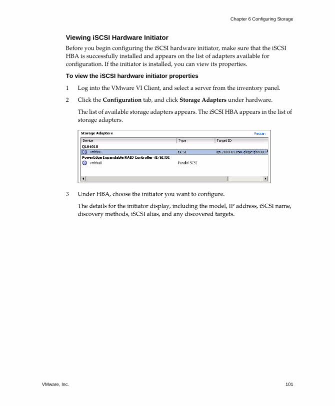
VMware, Inc. 101
Chapter 6 Configuring Storage
Viewing iSCSI Hardware InitiatorBefore you begin configuring the iSCSI hardware initiator, make sure that the iSCSI HBA is successfully installed and appears on the list of adapters available for configuration. If the initiator is installed, you can view its properties.
To view the iSCSI hardware initiator properties
1 Log into the VMware VI Client, and select a server from the inventory panel.
2 Click the Configuration tab, and click Storage Adapters under hardware.
The list of available storage adapters appears. The iSCSI HBA appears in the list of storage adapters.
3 Under HBA, choose the initiator you want to configure.
The details for the initiator display, including the model, IP address, iSCSI name, discovery methods, iSCSI alias, and any discovered targets.
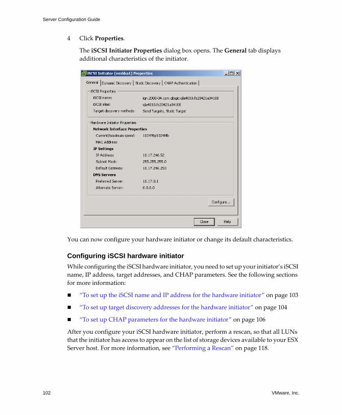
Server Configuration Guide
102 VMware, Inc.
4 Click Properties.
The iSCSI Initiator Properties dialog box opens. The General tab displays additional characteristics of the initiator.
You can now configure your hardware initiator or change its default characteristics.
Configuring iSCSI hardware initiatorWhile configuring the iSCSI hardware initiator, you need to set up your initiator�s iSCSI name, IP address, target addresses, and CHAP parameters. See the following sections for more information:
! �To set up the iSCSI name and IP address for the hardware initiator� on page 103
! �To set up target discovery addresses for the hardware initiator� on page 104
! �To set up CHAP parameters for the hardware initiator� on page 106
After you configure your iSCSI hardware initiator, perform a rescan, so that all LUNs that the initiator has access to appear on the list of storage devices available to your ESX Server host. For more information, see �Performing a Rescan� on page 118.
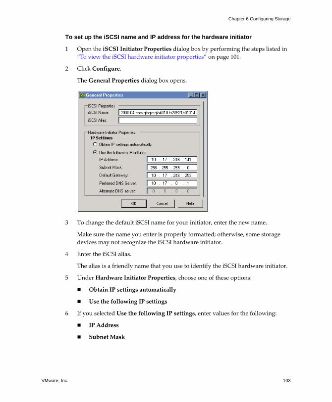
VMware, Inc. 103
Chapter 6 Configuring Storage
To set up the iSCSI name and IP address for the hardware initiator
1 Open the iSCSI Initiator Properties dialog box by performing the steps listed in �To view the iSCSI hardware initiator properties� on page 101.
2 Click Configure.
The General Properties dialog box opens.
3 To change the default iSCSI name for your initiator, enter the new name.
Make sure the name you enter is properly formatted; otherwise, some storage devices may not recognize the iSCSI hardware initiator.
4 Enter the iSCSI alias.
The alias is a friendly name that you use to identify the iSCSI hardware initiator.
5 Under Hardware Initiator Properties, choose one of these options:
! Obtain IP settings automatically
! Use the following IP settings
6 If you selected Use the following IP settings, enter values for the following:
! IP Address
! Subnet Mask
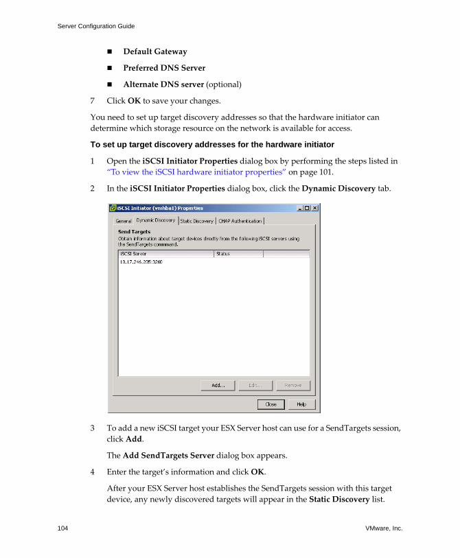
Server Configuration Guide
104 VMware, Inc.
! Default Gateway
! Preferred DNS Server
! Alternate DNS server (optional)
7 Click OK to save your changes.
You need to set up target discovery addresses so that the hardware initiator can determine which storage resource on the network is available for access.
To set up target discovery addresses for the hardware initiator
1 Open the iSCSI Initiator Properties dialog box by performing the steps listed in �To view the iSCSI hardware initiator properties� on page 101.
2 In the iSCSI Initiator Properties dialog box, click the Dynamic Discovery tab.
3 To add a new iSCSI target your ESX Server host can use for a SendTargets session, click Add.
The Add SendTargets Server dialog box appears.
4 Enter the target�s information and click OK.
After your ESX Server host establishes the SendTargets session with this target device, any newly discovered targets will appear in the Static Discovery list.
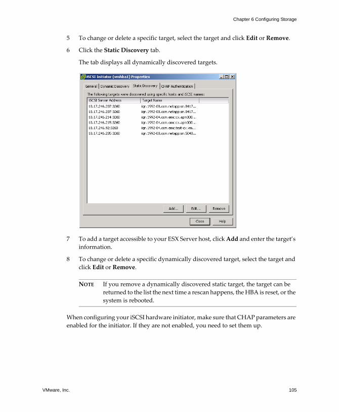
VMware, Inc. 105
Chapter 6 Configuring Storage
5 To change or delete a specific target, select the target and click Edit or Remove.
6 Click the Static Discovery tab.
The tab displays all dynamically discovered targets.
7 To add a target accessible to your ESX Server host, click Add and enter the target�s information.
8 To change or delete a specific dynamically discovered target, select the target and click Edit or Remove.
NOTE If you remove a dynamically discovered static target, the target can be returned to the list the next time a rescan happens, the HBA is reset, or the system is rebooted.
When configuring your iSCSI hardware initiator, make sure that CHAP parameters are enabled for the initiator. If they are not enabled, you need to set them up.
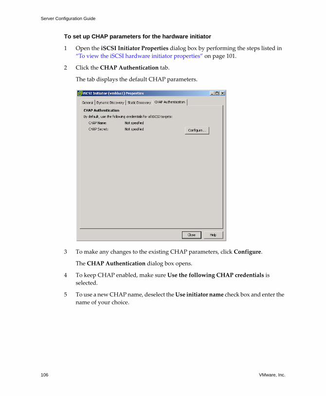
Server Configuration Guide
106 VMware, Inc.
To set up CHAP parameters for the hardware initiator
1 Open the iSCSI Initiator Properties dialog box by performing the steps listed in �To view the iSCSI hardware initiator properties� on page 101.
2 Click the CHAP Authentication tab.
The tab displays the default CHAP parameters.
3 To make any changes to the existing CHAP parameters, click Configure.
The CHAP Authentication dialog box opens.
4 To keep CHAP enabled, make sure Use the following CHAP credentials is selected.
5 To use a new CHAP name, deselect the Use initiator name check box and enter the name of your choice.
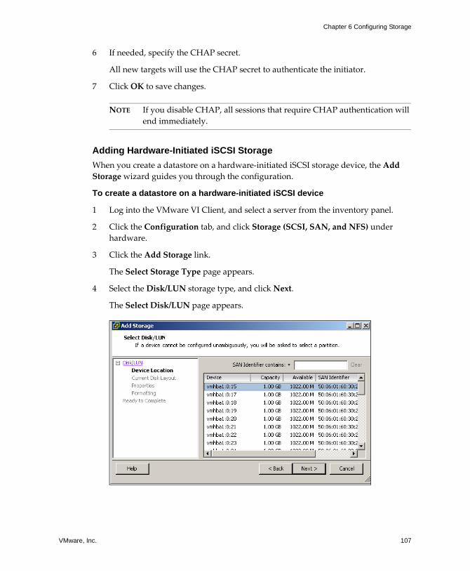
VMware, Inc. 107
Chapter 6 Configuring Storage
6 If needed, specify the CHAP secret.
All new targets will use the CHAP secret to authenticate the initiator.
7 Click OK to save changes.
NOTE If you disable CHAP, all sessions that require CHAP authentication will end immediately.
Adding Hardware-Initiated iSCSI StorageWhen you create a datastore on a hardware‐initiated iSCSI storage device, the Add Storage wizard guides you through the configuration.
To create a datastore on a hardware-initiated iSCSI device
1 Log into the VMware VI Client, and select a server from the inventory panel.
2 Click the Configuration tab, and click Storage (SCSI, SAN, and NFS) under hardware.
3 Click the Add Storage link.
The Select Storage Type page appears.
4 Select the Disk/LUN storage type, and click Next.
The Select Disk/LUN page appears.
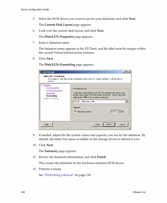
Server Configuration Guide
108 VMware, Inc.
5 Select the iSCSI device you want to use for your datastore, and click Next.
The Current Disk Layout page appears.
6 Look over the current disk layout, and click Next.
The Disk/LUN�Properties page appears.
7 Enter a datastore name.
The datastore name appears in the VI Client, and the label must be unique within the current Virtual Infrastructure instance.
8 Click Next.
The Disk/LUN�Formatting page appears.
9 If needed, adjust the file system values and capacity you use for the datastore. By default, the entire free space available on the storage device is offered to you.
10 Click Next.
The Summary page appears.
11 Review the datastore information, and click Finish.
This creates the datastore on the hardware‐initiated iSCSI device.
12 Perform a rescan.
See �Performing a Rescan� on page 118.
VMware, Inc. 109
Chapter 6 Configuring Storage
Configuring Software-Initiated iSCSI StorageWith the software‐based iSCSI implementation, you can use a standard network adapter to connect your ESX Server system to a remote iSCSI target on the IP network. The ESX Server software iSCSI initiator built into VMkernel facilitates this connection communicating with the network adapter through the network stack.
Before configuring software‐based iSCSI storage, enable network connectivity and configure the iSCSI software initiator.
Use the following procedure when preparing and setting up datastores that use iSCSI software‐initiated connection to access the iSCSI storage:
1 Configure the VMkernel TCP/IP networking stack.
See �VMkernel Configuration� on page 19 and �Networking Configuration for Software iSCSI Storage� on page 56.
2 Open a firewall port by enabling the iSCSI software client service.
See �Opening Firewall Ports for Supported Services and Management Agents� on page 185.
3 Configure the iSCSI software initiator.
See�Configuring iSCSI Software Initiator� on page 111.
4 Rescan for new iSCSI LUNs.
See �Performing a Rescan� on page 118.
5 Set up the datastore.
See �Adding Software‐Initiated iSCSI Storage� on page 116.
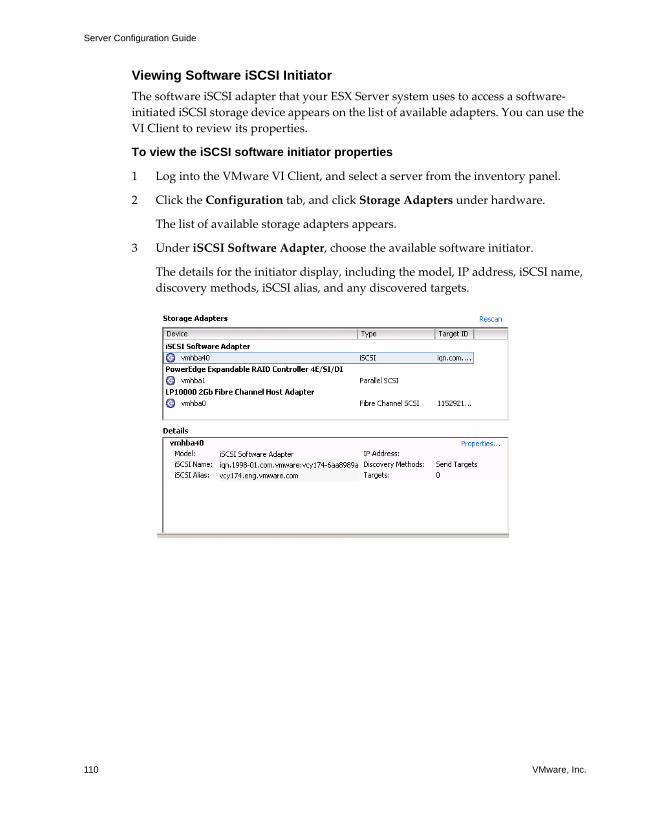
Server Configuration Guide
110 VMware, Inc.
Viewing Software iSCSI InitiatorThe software iSCSI adapter that your ESX Server system uses to access a software‐initiated iSCSI storage device appears on the list of available adapters. You can use the VI Client to review its properties.
To view the iSCSI software initiator properties
1 Log into the VMware VI Client, and select a server from the inventory panel.
2 Click the Configuration tab, and click Storage Adapters under hardware.
The list of available storage adapters appears.
3 Under iSCSI Software Adapter, choose the available software initiator.
The details for the initiator display, including the model, IP address, iSCSI name, discovery methods, iSCSI alias, and any discovered targets.
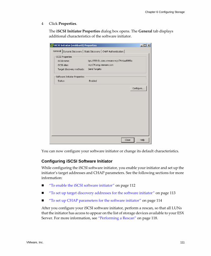
VMware, Inc. 111
Chapter 6 Configuring Storage
4 Click Properties.
The iSCSI Initiator Properties dialog box opens. The General tab displays additional characteristics of the software initiator.
You can now configure your software initiator or change its default characteristics.
Configuring iSCSI Software InitiatorWhile configuring the iSCSI software initiator, you enable your initiator and set up the initiator�s target addresses and CHAP parameters. See the following sections for more information:
! �To enable the iSCSI software initiator� on page 112
! �To set up target discovery addresses for the software initiator� on page 113
! �To set up CHAP parameters for the software initiator� on page 114
After you configure your iSCSI software initiator, perform a rescan, so that all LUNs that the initiator has access to appear on the list of storage devices available to your ESX Server. For more information, see �Performing a Rescan� on page 118.
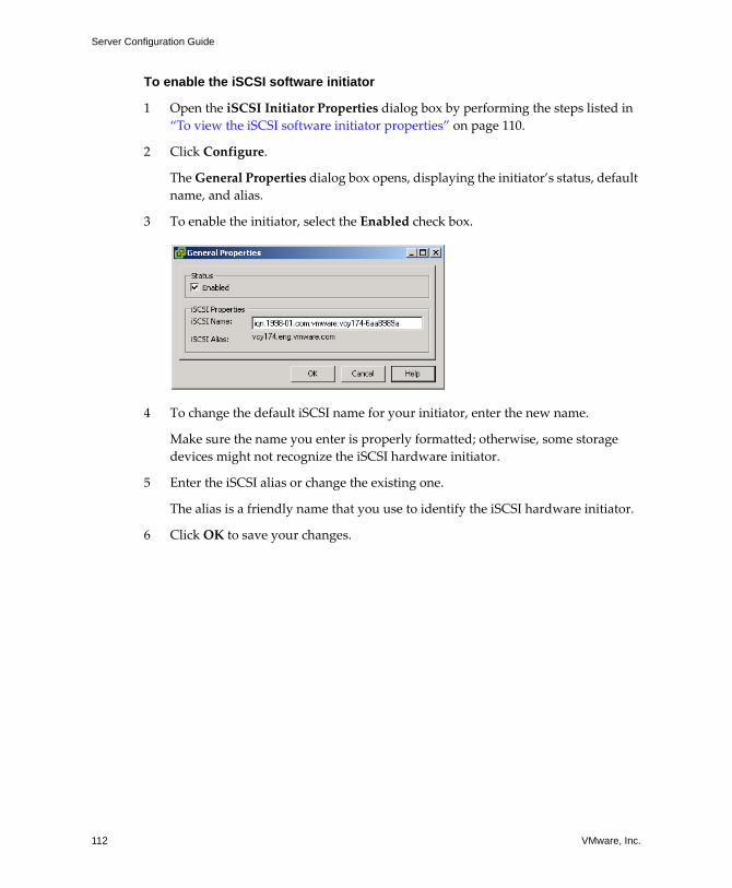
Server Configuration Guide
112 VMware, Inc.
To enable the iSCSI software initiator
1 Open the iSCSI Initiator Properties dialog box by performing the steps listed in �To view the iSCSI software initiator properties� on page 110.
2 Click Configure.
The General Properties dialog box opens, displaying the initiator�s status, default name, and alias.
3 To enable the initiator, select the Enabled check box.
4 To change the default iSCSI name for your initiator, enter the new name.
Make sure the name you enter is properly formatted; otherwise, some storage devices might not recognize the iSCSI hardware initiator.
5 Enter the iSCSI alias or change the existing one.
The alias is a friendly name that you use to identify the iSCSI hardware initiator.
6 Click OK to save your changes.
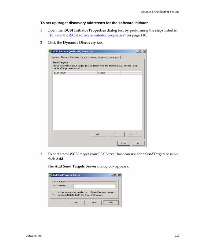
VMware, Inc. 113
Chapter 6 Configuring Storage
To set up target discovery addresses for the software initiator
1 Open the iSCSI Initiator Properties dialog box by performing the steps listed in �To view the iSCSI software initiator properties� on page 110.
2 Click the Dynamic Discovery tab.
3 To add a new iSCSI target your ESX Server host can use for a SendTargets session, click Add.
The Add Send Targets Server dialog box appears.
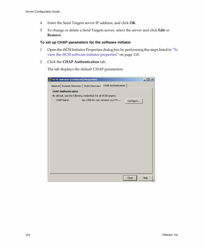
Server Configuration Guide
114 VMware, Inc.
4 Enter the Send Targets server IP address, and click OK.
5 To change or delete a Send Targets server, select the server and click Edit or Remove.
To set up CHAP parameters for the software initiator
1 Open the iSCSI Initiator Properties dialog box by performing the steps listed in �To view the iSCSI software initiator properties� on page 110.
2 Click the CHAP Authentication tab.
The tab displays the default CHAP parameters.
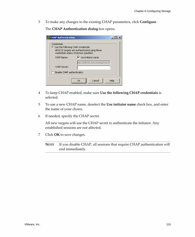
VMware, Inc. 115
Chapter 6 Configuring Storage
3 To make any changes to the existing CHAP parameters, click Configure.
The CHAP Authentication dialog box opens.
4 To keep CHAP enabled, make sure Use the following CHAP credentials is selected.
5 To use a new CHAP name, deselect the Use initiator name check box, and enter the name of your choice.
6 If needed, specify the CHAP secret.
All new targets will use the CHAP secret to authenticate the initiator. Any established sessions are not affected.
7 Click OK to save changes.
NOTE If you disable CHAP, all sessions that require CHAP authentication will end immediately.
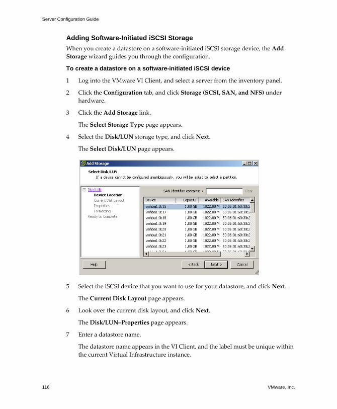
Server Configuration Guide
116 VMware, Inc.
Adding Software-Initiated iSCSI StorageWhen you create a datastore on a software‐initiated iSCSI storage device, the Add Storage wizard guides you through the configuration.
To create a datastore on a software-initiated iSCSI device
1 Log into the VMware VI Client, and select a server from the inventory panel.
2 Click the Configuration tab, and click Storage (SCSI, SAN, and NFS) under hardware.
3 Click the Add Storage link.
The Select Storage Type page appears.
4 Select the Disk/LUN storage type, and click Next.
The Select Disk/LUN page appears.
5 Select the iSCSI device that you want to use for your datastore, and click Next.
The Current Disk Layout page appears.
6 Look over the current disk layout, and click Next.
The Disk/LUN�Properties page appears.
7 Enter a datastore name.
The datastore name appears in the VI Client, and the label must be unique within the current Virtual Infrastructure instance.
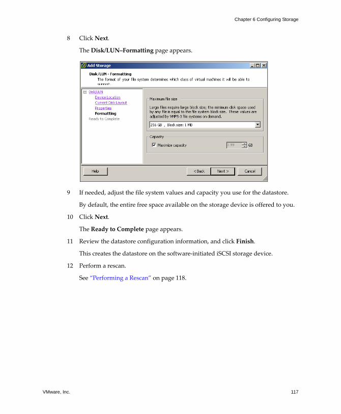
VMware, Inc. 117
Chapter 6 Configuring Storage
8 Click Next.
The Disk/LUN�Formatting page appears.
9 If needed, adjust the file system values and capacity you use for the datastore.
By default, the entire free space available on the storage device is offered to you.
10 Click Next.
The Ready to Complete page appears.
11 Review the datastore configuration information, and click Finish.
This creates the datastore on the software‐initiated iSCSI storage device.
12 Perform a rescan.
See �Performing a Rescan� on page 118.
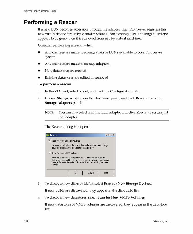
Server Configuration Guide
118 VMware, Inc.
Performing a RescanIf a new LUN becomes accessible through the adapter, then ESX Server registers this new virtual device for use by virtual machines. If an existing LUN is no longer used and appears to be gone, then it is removed from use by virtual machines.
Consider performing a rescan when:
! Any changes are made to storage disks or LUNs available to your ESX Server system
! Any changes are made to storage adapters
! New datastores are created
! Existing datastores are edited or removed
To perform a rescan
1 In the VI Client, select a host, and click the Configuration tab.
2 Choose Storage Adapters in the Hardware panel, and click Rescan above the Storage Adapters panel.
NOTE You can also select an individual adapter and click Rescan to rescan just that adapter.
The Rescan dialog box opens.
3 To discover new disks or LUNs, select Scan for New Storage Devices.
If new LUNs are discovered, they appear in the disk/LUN list.
4 To discover new datastores, select Scan for New VMFS Volumes.
If new datastores or VMFS volumes are discovered, they appear in the datastore list.
VMware, Inc. 119
Chapter 6 Configuring Storage
Network Attached StorageThis section contains information about network attached storage (NAS) and provides the following information:
! �Shared Storage Capabilities� on page 119
! �How Virtual Machines Use NFS� on page 119
! �Managing NFS Devices� on page 122
! �Configuring ESX Server to Access NFS Volumes� on page 122
! �Creating an NFS‐Based Datastore� on page 122
ESX Server supports using network attached storage (NAS) through the NFS protocol. For some users, NFS might be a more cost‐effective alternative to SAN storage.
Shared Storage CapabilitiesESX Server supports the following shared storage capabilities on NFS volumes:
! Use VMotion. Move running virtual machines from one ESX Server to another without service interruption.
! Create virtual machines on NFS mounted volumes.
! Boot virtual machines stored on NFS mounted volumes.
! Create virtual machine snapshots on NFS mounted volumes. The snapshot feature lets you preserve the state of the virtual machine so you can return to the same state repeatedly.
How Virtual Machines Use NFSThe NFS protocol that ESX Server supports enables communication between an NFS client and NFS server. The client issues requests for information from the server which replies with the result.
The NFS client built into ESX Server lets you access the NFS server and use NFS volumes to store virtual machine disks. ESX Server supports NFS Version 3 over TCP only.
You use the VI Client to configure NFS volumes as datastores. Configured NFS datastores appear in the VI Client and you can use them to store virtual disk files in the same way you use VMFS‐based datastores.
Server Configuration Guide
120 VMware, Inc.
Before storing virtual disk files on NFS‐based datastores, you might need to configure a special user, known as a delegate user, at the ESX Server level in order for ESX Server users to perform operations on the virtual machine files.
NOTE Changing the delegate user for an ESX Server host is experimental and, currently, VMware provides limited support for this feature. Use of this feature may result in unexpected behavior. For more information, see �Virtual Machine Delegates for NFS Storage� on page 229.
The virtual disks that you create on NFS‐based datastores use a disk format dictated by the NFS server, typically a thin disk format that requires on demand space allocation. If the virtual machine runs out of space while writing to this disk, the VI Client notifies you that more space is needed. You have the following options:
! Free up additional space on the volume, so that the virtual machine continues writing to the disk.
! Terminate the virtual machine session. Terminating the session, shuts down the virtual machine.
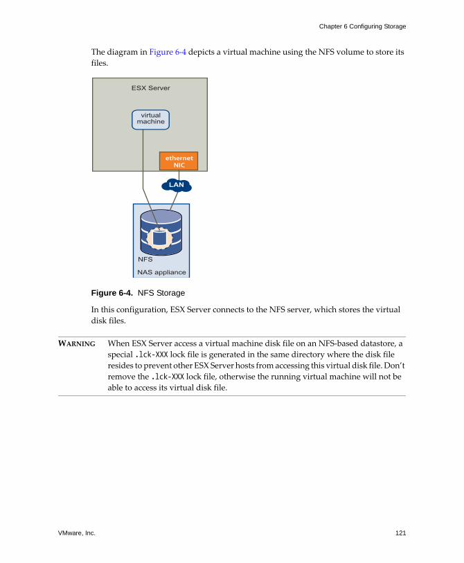
VMware, Inc. 121
Chapter 6 Configuring Storage
The diagram in Figure 6‐4 depicts a virtual machine using the NFS volume to store its files.
Figure 6-4. NFS Storage
In this configuration, ESX Server connects to the NFS server, which stores the virtual disk files.
WARNING When ESX Server access a virtual machine disk file on an NFS‐based datastore, a special .lck-XXX lock file is generated in the same directory where the disk file resides to prevent other ESX Server hosts from accessing this virtual disk file. Don�t remove the .lck-XXX lock file, otherwise the running virtual machine will not be able to access its virtual disk file.
NAS appliance
NFS
virtualmachine
LAN
ethernetNIC
ESX Server
Server Configuration Guide
122 VMware, Inc.
Managing NFS DevicesUsing the VI Client, you can register and manage NFS volumes for your ESX Server. The management interface for storage lists registered NFS volumes.
Configuring ESX Server to Access NFS VolumesNFS requires network connectivity to access data stored on remote servers. Before configuring NFS, you must first configure networking for VMotion and IP storage.
For information on configuring a network, see �VMkernel Configuration� on page 19.
Creating an NFS-Based DatastoreWhen you create a datastore on an NFS volume, the Add Storage wizard guides you through the configuration steps.
To mount an NFS volume
1 Log into the VMware VI Client, and select a server from the inventory panel.
2 Click the Configuration tab, and click Storage (SCSI, SAN, and NFS) under hardware.
3 Click the Add Storage link.
The Select Storage Type page appears.
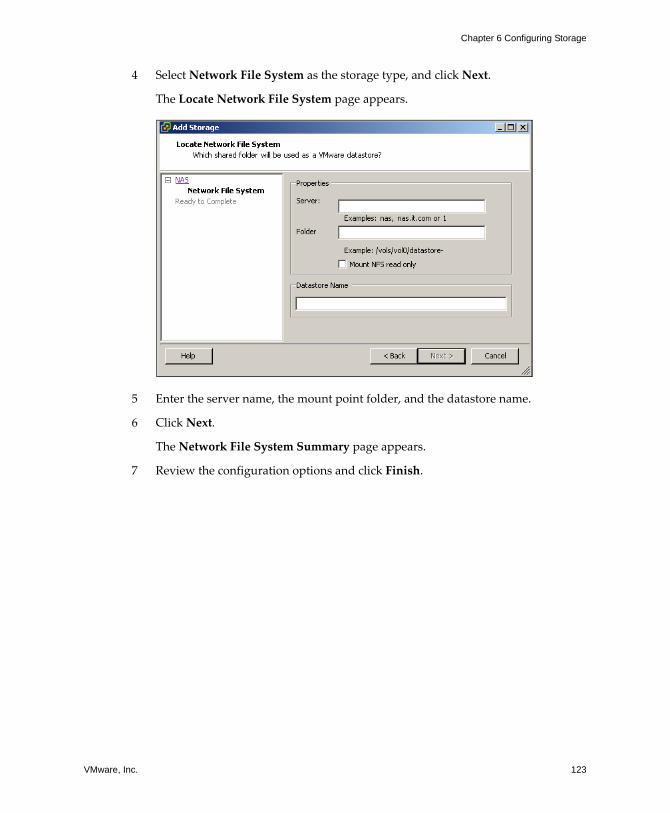
VMware, Inc. 123
Chapter 6 Configuring Storage
4 Select Network File System as the storage type, and click Next.
The Locate Network File System page appears.
5 Enter the server name, the mount point folder, and the datastore name.
6 Click Next.
The Network File System Summary page appears.
7 Review the configuration options and click Finish.

Server Configuration Guide
124 VMware, Inc.
VMware, Inc. 125
CHAPTER 7 Managing Storage
This chapter contains information about managing existing datastores and file systems that comprise datastores. The chapter covers the following sections:
! �Managing Datastores and File Systems� on page 126
! �Editing Existing VMFS‐based Datastores� on page 127
! �Managing Paths for Fibre Channel and iSCSI� on page 132
! �The vmkfstools Commands� on page 139
Server Configuration Guide
126 VMware, Inc.
Managing Datastores and File SystemsAn ESX Server system uses datastores to store all files associated with its virtual machines. The datastore is a logical storage unit, which can use disk space on one physical device, one disk partition, or span several physical devices. The datastore can exist on different types of physical devices including SCSI, iSCSI, Fibre Channel SAN, or NFS.
For more information on datastores, see �Datastores and File Systems� on page 76.
Datastores are added to the VI Client in one of two ways:
! Discovered when a host is added to the inventory � When you add a host to the inventory, the VI Client displays any datastores that the host can recognize.
! Created on an available storage device � You can use the Add Storage command to create and configure a new datastore.
After you create the datastores, you can use them to store virtual machine files. When needed, you can modify the datastores. For example, you can add extents to your datastore, rename, or remove it.
Adding New DatastoresYou can create a datastore on a Fibre Channel, iSCSI, or local SCSI disk. You can also mount an NFS volume over a network connection and use it as a VMware datastore. To create a datastore, choose the type of datastore you want to create using the following options:
! �Adding Local SCSI Storage� on page 90
! �Adding Fibre Channel Storage� on page 94
! �Adding Hardware‐Initiated iSCSI Storage� on page 107
! �Adding Software‐Initiated iSCSI Storage� on page 116
! �Creating an NFS‐Based Datastore� on page 122
VMware, Inc. 127
Chapter 7 Managing Storage
Removing Existing DatastoresYou can remove a datastore that you don�t use.
CAUTION Removing a datastore from the ESX Server system breaks the connection between the system and the storage device that holds the datastore and stops all functions of that storage device.
You cannot remove a datastore if it holds virtual disks of a currently running virtual machine.
To remove a datastore
1 Log into the VMware VI Client, and select a server from the inventory panel.
2 Click the Configuration tab, and click Storage (SCSI, SAN, and NFS).
3 Select the datastore you want to remove, and click Remove.
4 Confirm that you want to remove the datastore.
Editing Existing VMFS-based DatastoresDatastores that use the VMFS format are deployed on SCSI‐based storage devices.
After you create a VMFS‐based datastore, you can modify it. See the following sections for more information:
! �Upgrading Datastores� on page 127
! �Changing the Names of Datastores� on page 129
! �Adding Extents to Datastores� on page 130
Upgrading DatastoresESX Server 3 includes a new file system, VMFS version 3 (VMFS‐3). If your datastore was formatted with VMFS‐2, you can only read files stored on VMFS‐2, but you are not able to use them. To use the files, upgrade VMFS‐2 to VMFS‐3.
When upgrading VMFS‐2 to VMFS‐3, the ESX Server file‐locking mechanism ensures that no remote ESX Server or local process is accessing the VMFS volume being converted. ESX Server preserves all files on the datastore.
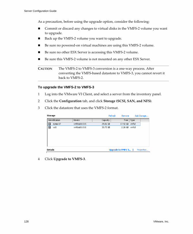
Server Configuration Guide
128 VMware, Inc.
As a precaution, before using the upgrade option, consider the following:
! Commit or discard any changes to virtual disks in the VMFS‐2 volume you want to upgrade.
! Back up the VMFS‐2 volume you want to upgrade.
! Be sure no powered‐on virtual machines are using this VMFS‐2 volume.
! Be sure no other ESX Server is accessing this VMFS‐2 volume.
! Be sure this VMFS‐2 volume is not mounted on any other ESX Server.
CAUTION The VMFS‐2 to VMFS‐3 conversion is a one‐way process. After converting the VMFS‐based datastore to VMFS‐3, you cannot revert it back to VMFS‐2.
To upgrade the VMFS-2 to VMFS-3
1 Log into the VMware VI Client, and select a server from the inventory panel.
2 Click the Configuration tab, and click Storage (SCSI, SAN, and NFS).
3 Click the datastore that uses the VMFS‐2 format.
4 Click Upgrade to VMFS‐3.
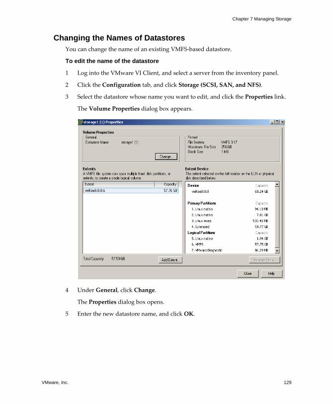
VMware, Inc. 129
Chapter 7 Managing Storage
Changing the Names of DatastoresYou can change the name of an existing VMFS‐based datastore.
To edit the name of the datastore
1 Log into the VMware VI Client, and select a server from the inventory panel.
2 Click the Configuration tab, and click Storage (SCSI, SAN, and NFS).
3 Select the datastore whose name you want to edit, and click the Properties link.
The Volume Properties dialog box appears.
4 Under General, click Change.
The Properties dialog box opens.
5 Enter the new datastore name, and click OK.
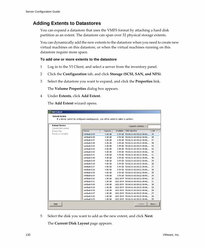
Server Configuration Guide
130 VMware, Inc.
Adding Extents to DatastoresYou can expand a datastore that uses the VMFS format by attaching a hard disk partition as an extent. The datastore can span over 32 physical storage extents.
You can dynamically add the new extents to the datastore when you need to create new virtual machines on this datastore, or when the virtual machines running on this datastore require more space.
To add one or more extents to the datastore
1 Log in to the VI Client, and select a server from the inventory panel.
2 Click the Configuration tab, and click Storage (SCSI, SAN, and NFS).
3 Select the datastore you want to expand, and click the Properties link.
The Volume Properties dialog box appears.
4 Under Extents, click Add Extent.
The Add Extent wizard opens.
5 Select the disk you want to add as the new extent, and click Next.
The Current Disk Layout page appears.
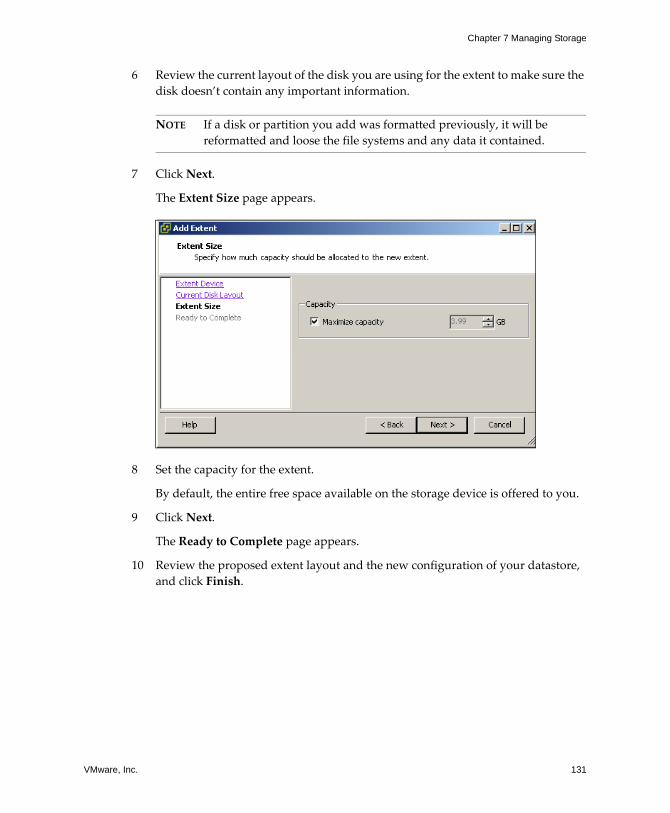
VMware, Inc. 131
Chapter 7 Managing Storage
6 Review the current layout of the disk you are using for the extent to make sure the disk doesn�t contain any important information.
NOTE If a disk or partition you add was formatted previously, it will be reformatted and loose the file systems and any data it contained.
7 Click Next.
The Extent Size page appears.
8 Set the capacity for the extent.
By default, the entire free space available on the storage device is offered to you.
9 Click Next.
The Ready to Complete page appears.
10 Review the proposed extent layout and the new configuration of your datastore, and click Finish.

Server Configuration Guide
132 VMware, Inc.
Managing Paths for Fibre Channel and iSCSIESX Server supports multipathing to maintain a constant connection between the server machine and the storage device in case of the failure of an HBA, switch, storage processor (SP), or cable. Multipathing support does not require specific failover drivers.
To support path switching, the server typically has two or more HBAs available, from which the storage array can be reached using one or more switches. Alternatively, the setup could include one HBA and two storage processors so that the HBA can use a different path to reach the disk array.
By default, ESX Server systems use only one path from the host to a given LUN at any given time. If the path being used by the ESX Server system fails, the server selects another of the available paths. The process of detecting a failed path and switching to another is called path failover. A path fails if any of the components�HBA, cable, switch port, or storage processor�along the path fails.
Figure 7-1. Multipathing
In Figure 7‐1, multiple paths connect each server with the storage device. For example, if HBA1 or the link between HBA1 and the switch fails, HBA2 takes over and provides the connection between the server and the switch. The process of one HBA taking over for another is called HBA failover.
ESXServer
ESXServer
SP2
storage array
SP1
switch switch
HBA2 HBA1 HBA3 HBA4
VMware, Inc. 133
Chapter 7 Managing Storage
Similarly, if SP1 or the link between SP1 and the switch breaks, SP2 takes over and provides the connection between the switch and the storage device. This process is called SP failover. VMware ESX Server supports both HBA and SP failover with its multipathing capability.
For more information on multipathing, refer to the SAN Configuration Guide.
For information on managing paths, see the following sections.
! �Viewing the Current Multipathing State� on page 133
! �Active Paths� on page 135
! �Setting Multipathing Policies for LUNs� on page 136
! �Disabling and Enabling Paths� on page 137
! �Setting the Preferred Path (Fixed Path Policy Only)� on page 138
Viewing the Current Multipathing StateUse the VI Client to view the current multipathing state.
To view the current multipathing state
1 Log into the VMware VI Client, and select a server from the inventory panel.
2 Click the Configuration tab, and click Storage (SCSI, SAN, and NFS) under hardware.
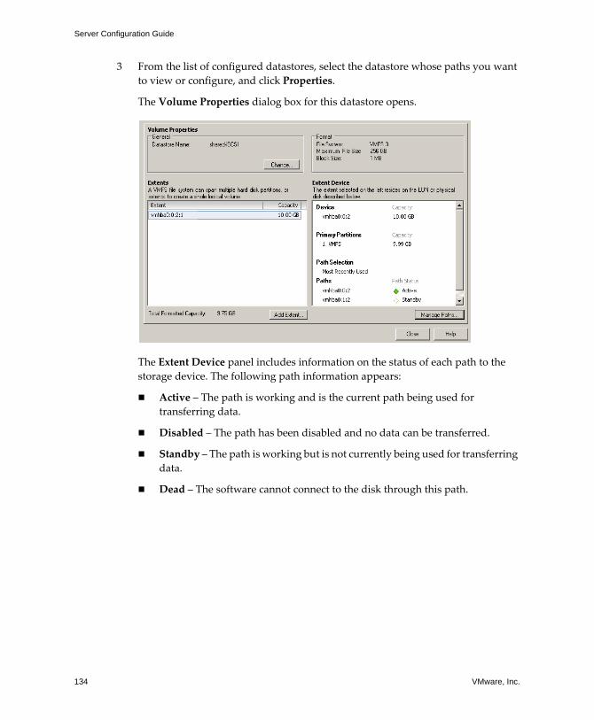
Server Configuration Guide
134 VMware, Inc.
3 From the list of configured datastores, select the datastore whose paths you want to view or configure, and click Properties.
The Volume Properties dialog box for this datastore opens.
The Extent Device panel includes information on the status of each path to the storage device. The following path information appears:
! Active � The path is working and is the current path being used for transferring data.
! Disabled � The path has been disabled and no data can be transferred.
! Standby � The path is working but is not currently being used for transferring data.
! Dead � The software cannot connect to the disk through this path.
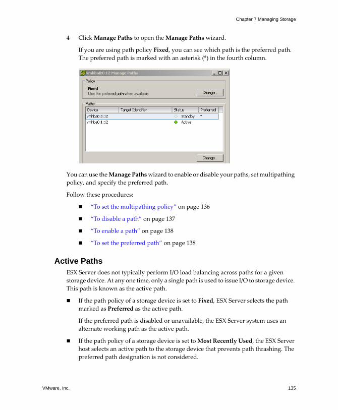
VMware, Inc. 135
Chapter 7 Managing Storage
4 Click Manage Paths to open the Manage Paths wizard.
If you are using path policy Fixed, you can see which path is the preferred path. The preferred path is marked with an asterisk (*) in the fourth column.
You can use the Manage Paths wizard to enable or disable your paths, set multipathing policy, and specify the preferred path.
Follow these procedures:
! �To set the multipathing policy� on page 136
! �To disable a path� on page 137
! �To enable a path� on page 138
! �To set the preferred path� on page 138
Active PathsESX Server does not typically perform I/O load balancing across paths for a given storage device. At any one time, only a single path is used to issue I/O to storage device. This path is known as the active path.
! If the path policy of a storage device is set to Fixed, ESX Server selects the path marked as Preferred as the active path.
If the preferred path is disabled or unavailable, the ESX Server system uses an alternate working path as the active path.
! If the path policy of a storage device is set to Most Recently Used, the ESX Server host selects an active path to the storage device that prevents path thrashing. The preferred path designation is not considered.
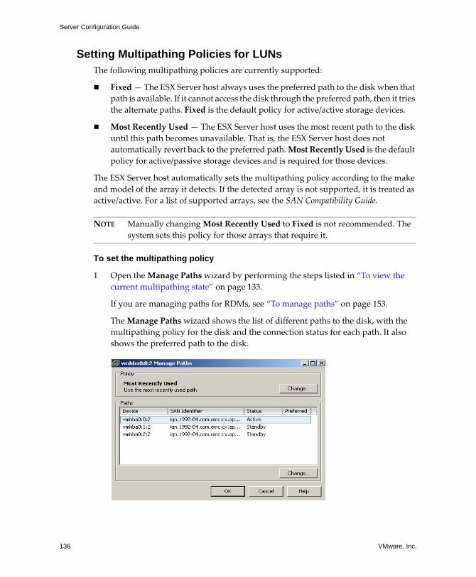
Server Configuration Guide
136 VMware, Inc.
Setting Multipathing Policies for LUNsThe following multipathing policies are currently supported:
! Fixed � The ESX Server host always uses the preferred path to the disk when that path is available. If it cannot access the disk through the preferred path, then it tries the alternate paths. Fixed is the default policy for active/active storage devices.
! Most Recently Used � The ESX Server host uses the most recent path to the disk until this path becomes unavailable. That is, the ESX Server host does not automatically revert back to the preferred path. Most Recently Used is the default policy for active/passive storage devices and is required for those devices.
The ESX Server host automatically sets the multipathing policy according to the make and model of the array it detects. If the detected array is not supported, it is treated as active/active. For a list of supported arrays, see the SAN Compatibility Guide.
NOTE Manually changing Most Recently Used to Fixed is not recommended. The system sets this policy for those arrays that require it.
To set the multipathing policy
1 Open the Manage Paths wizard by performing the steps listed in �To view the current multipathing state� on page 133.
If you are managing paths for RDMs, see �To manage paths� on page 153.
The Manage Paths wizard shows the list of different paths to the disk, with the multipathing policy for the disk and the connection status for each path. It also shows the preferred path to the disk.
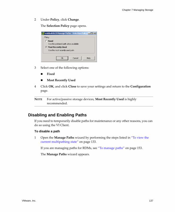
VMware, Inc. 137
Chapter 7 Managing Storage
2 Under Policy, click Change.
The Selection Policy page opens.
3 Select one of the following options:
! Fixed
! Most Recently Used
4 Click OK, and click Close to save your settings and return to the Configuration page.
NOTE For active/passive storage devices, Most Recently Used is highly recommended.
Disabling and Enabling PathsIf you need to temporarily disable paths for maintenance or any other reasons, you can do so using the VI Client.
To disable a path
1 Open the Manage Paths wizard by performing the steps listed in �To view the current multipathing state� on page 133.
If you are managing paths for RDMs, see �To manage paths� on page 153.
The Manage Paths wizard appears.
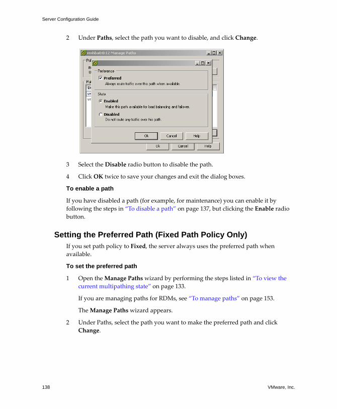
Server Configuration Guide
138 VMware, Inc.
2 Under Paths, select the path you want to disable, and click Change.
3 Select the Disable radio button to disable the path.
4 Click OK twice to save your changes and exit the dialog boxes.
To enable a path
If you have disabled a path (for example, for maintenance) you can enable it by following the steps in �To disable a path� on page 137, but clicking the Enable radio button.
Setting the Preferred Path (Fixed Path Policy Only)If you set path policy to Fixed, the server always uses the preferred path when available.
To set the preferred path
1 Open the Manage Paths wizard by performing the steps listed in �To view the current multipathing state� on page 133.
If you are managing paths for RDMs, see �To manage paths� on page 153.
The Manage Paths wizard appears.
2 Under Paths, select the path you want to make the preferred path and click Change.
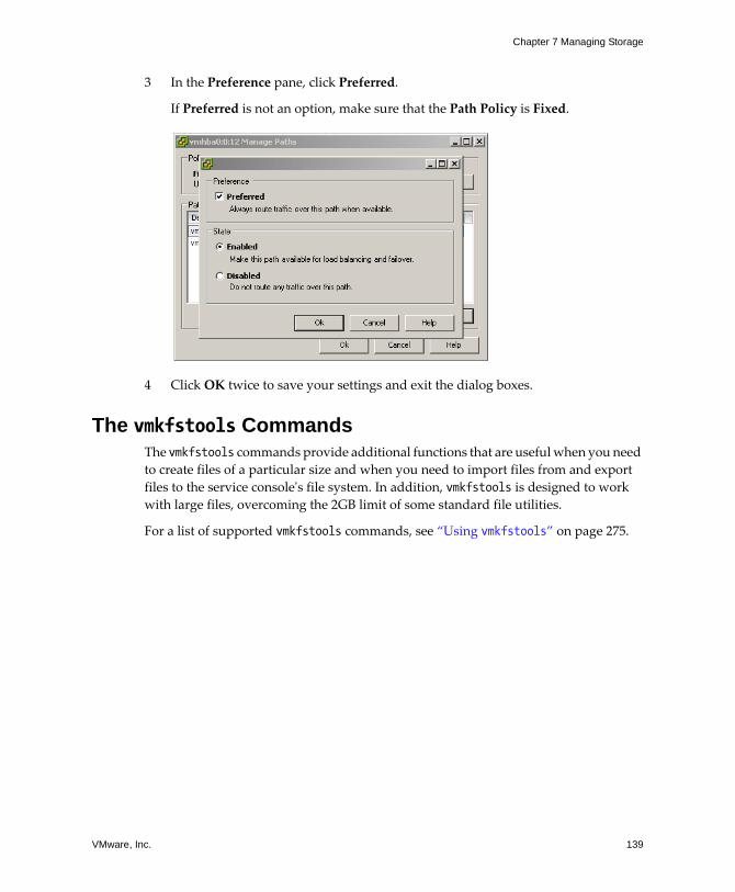
VMware, Inc. 139
Chapter 7 Managing Storage
3 In the Preference pane, click Preferred.
If Preferred is not an option, make sure that the Path Policy is Fixed.
4 Click OK twice to save your settings and exit the dialog boxes.
The vmkfstools CommandsThe vmkfstools commands provide additional functions that are useful when you need to create files of a particular size and when you need to import files from and export files to the service consoleʹs file system. In addition, vmkfstools is designed to work with large files, overcoming the 2GB limit of some standard file utilities.
For a list of supported vmkfstools commands, see �Using vmkfstools� on page 275.

Server Configuration Guide
140 VMware, Inc.
VMware, Inc. 141
CHAPTER 8 Raw Device Mapping
This chapter contains information about raw device mapping.
NOTE For information about configuring SANs, see the SAN Configuration Guide.
This chapter covers the following topics:
! �Overview� on page 142
! �Benefits of Raw Device Mapping� on page 144
! �Raw Device Mapping Characteristics� on page 147
! �Managing Raw Device Mappings� on page 151
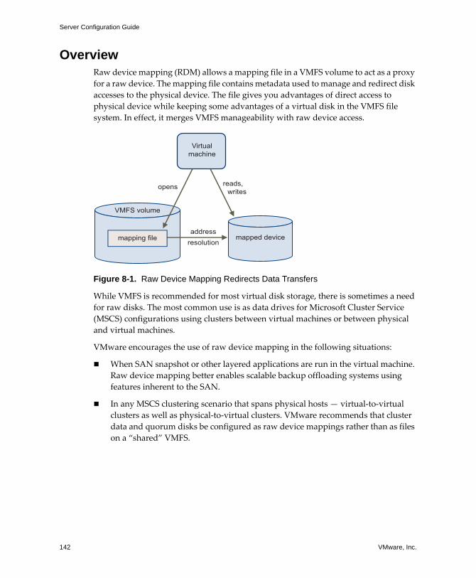
Server Configuration Guide
142 VMware, Inc.
OverviewRaw device mapping (RDM) allows a mapping file in a VMFS volume to act as a proxy for a raw device. The mapping file contains metadata used to manage and redirect disk accesses to the physical device. The file gives you advantages of direct access to physical device while keeping some advantages of a virtual disk in the VMFS file system. In effect, it merges VMFS manageability with raw device access.
Figure 8-1. Raw Device Mapping Redirects Data Transfers
While VMFS is recommended for most virtual disk storage, there is sometimes a need for raw disks. The most common use is as data drives for Microsoft Cluster Service (MSCS) configurations using clusters between virtual machines or between physical and virtual machines.
VMware encourages the use of raw device mapping in the following situations:
! When SAN snapshot or other layered applications are run in the virtual machine. Raw device mapping better enables scalable backup offloading systems using features inherent to the SAN.
! In any MSCS clustering scenario that spans physical hosts � virtual‐to‐virtual clusters as well as physical‐to‐virtual clusters. VMware recommends that cluster data and quorum disks be configured as raw device mappings rather than as files on a �shared� VMFS.
VMFS volume
Virtualmachine
addressresolution
opens reads, writes
mapped devicemapping file
VMware, Inc. 143
Chapter 8 Raw Device Mapping
Think of a raw device mapping as a symbolic link from a VMFS volume to a raw LUN. The mapping makes LUNs appear as files in a VMFS volume. The mapping file�not the raw LUN�is referenced in the virtual machine configuration. The mapping file contains a reference to the raw LUN. Using raw device mappings, you can:
! Use VMotion to migrate virtual machines using raw LUNs.
! Add raw LUNs to virtual machines using the Virtual Infrastructure Client.
! Use file system features such as distributed file locking, permissions, and naming.
Two compatibility modes are available for raw device mappings:
! Virtual compatibility mode allows a mapping to act exactly like a virtual disk file, including the use of snapshots.
! Physical compatibility mode allows direct access of the SCSI device, for those applications needing lower level control.
TerminologyIn contexts other than this one, such as discussions of the Virtual Infrastructure Client, raw device mapping can be described in terms such as �Mapping a raw device into a datastore,� �mapping a system LUN�, or �mapping a disk file to a physical disk volume.� These terms all refer to raw device mapping.
! Raw disk � A disk volume accessed by a virtual machine as an alternative to a virtual disk file. It might be accessed through a mapping file.
! Raw device � Any SCSI device accessed by a mapping file.
! RDM � Acronym for raw device mapping.
! Raw LUN � A logical disk located in a SAN.
! Mapping file � A VMFS file containing metadata used to map and manage a raw device. A synonym for raw device mapping.
! Mapping � An abbreviated term for a raw device mapping.
! Mapped device � A raw device managed by a mapping file.
! Metadata file � A mapping file.
! Compatibility mode � The virtualization type used for SCSI device access (physical or virtual).
Server Configuration Guide
144 VMware, Inc.
Benefits of Raw Device MappingRaw device mapping provides a number of benefits, but it shouldn�t be used in every situation. In general, virtual disk files are preferable to raw device mapping for manageability. However, when you need raw devices, you must use a mapping file. The following list highlights both the benefits and limitations of raw device mapping.
! User‐Friendly Persistent Names � Raw device mapping provides a user‐friendly name for a mapped device. When you use a mapping, you don�t need to refer to the device by its device name. You refer to it by the name of the mapping file, for example:
/vmfs/volumes/myVolume/myVMDirectory/myRawDisk.vmdk
! Dynamic Name Resolution � Raw device mapping stores unique identification information for each mapped device. The VMFS file system resolves each mapping to its current SCSI device, regardless of changes in the physical configuration of the server due to adapter hardware changes, path changes, device relocation, and so forth.
! Distributed File Locking � Raw device mapping makes it possible to use VMFS distributed locking for raw SCSI devices. Distributed locking on a raw device mapping makes it safe to use a shared raw LUN without losing data when two virtual machines on different servers try to access the same LUN.
! File Permissions � Raw device mapping makes file permissions possible. The permissions of the mapping file are enforced at file open time to protect the mapped volume.
! File System Operations � Raw device mapping makes it possible to use file system utilities to work with a mapped volume, using the mapping file as a proxy. Most operations that are valid for an ordinary file can be applied to the mapping file and are redirected to operate on the mapped device.
! Snapshots � Raw device mapping makes it possible to use virtual machine snapshots on a mapped volume.
NOTE Snapshots are not available when raw device mapping is used in physical compatibility mode.
! VMotion � Raw device mapping lets you migrate a virtual machine with VMotion. When you use raw device mapping, the mapping file acts as a proxy to allow
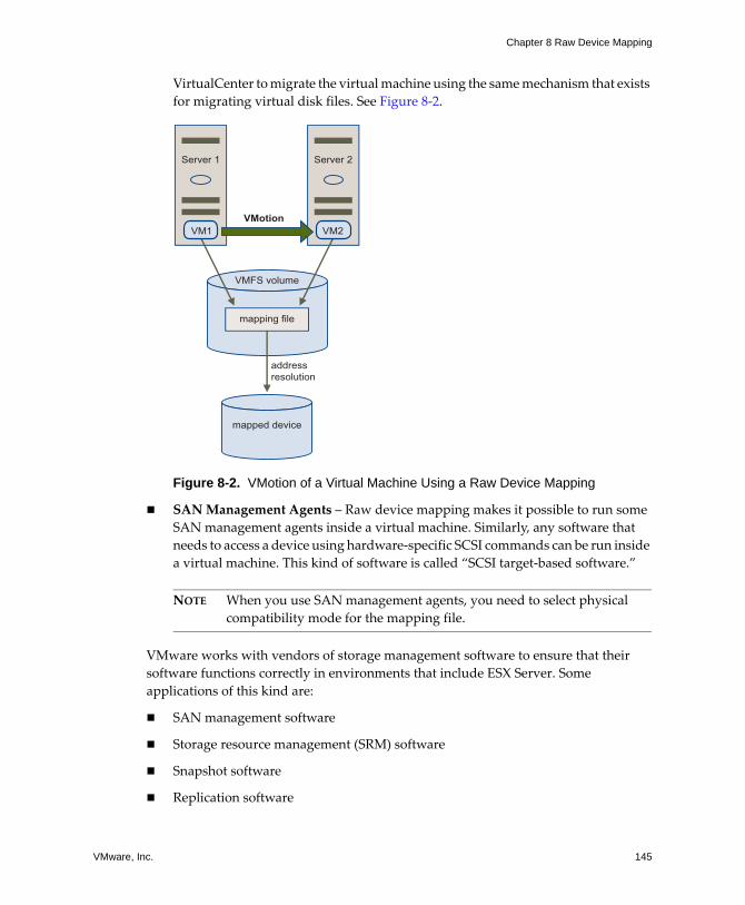
VMware, Inc. 145
Chapter 8 Raw Device Mapping
VirtualCenter to migrate the virtual machine using the same mechanism that exists for migrating virtual disk files. See Figure 8‐2.
Figure 8-2. VMotion of a Virtual Machine Using a Raw Device Mapping
! SAN Management Agents � Raw device mapping makes it possible to run some SAN management agents inside a virtual machine. Similarly, any software that needs to access a device using hardware‐specific SCSI commands can be run inside a virtual machine. This kind of software is called �SCSI target‐based software.�
NOTE When you use SAN management agents, you need to select physical compatibility mode for the mapping file.
VMware works with vendors of storage management software to ensure that their software functions correctly in environments that include ESX Server. Some applications of this kind are:
! SAN management software
! Storage resource management (SRM) software
! Snapshot software
! Replication software
VMFS volume
mapping file
addressresolution
mapped device
Server 2Server 1
VM2VM1VMotion
Server Configuration Guide
146 VMware, Inc.
Such software uses physical compatibility mode for raw device mappings, so that the software can access SCSI devices directly.
Various management products are best run centrally (not on the ESX Server machine), while others run well in the service console or in the virtual machines. VMware does not certify these applications or provide a compatibility matrix. To find out whether a SAN management application is supported in an ESX Server environment, contact the SAN management software provider.
Limitations of Raw Device MappingWhen planning to use raw device mapping, consider the following:
! Not Available for Block Devices or Certain RAID Devices � Raw device mapping (in the current implementation) uses a SCSI serial number to identify the mapped device. Because block devices and some direct‐attach RAID devices do not export serial numbers, they canʹt be used in raw device mappings.
! Available with VMFS‐2 and VMFS‐3 Volumes Only � Raw device mapping requires the VMFS‐2 or VMFS‐3 format. In ESX Server 3.0, the VMFS‐2 file system is read‐only. You need to upgrade it to VMFS‐3 to be able to use files it stores.
! No Snapshots in Physical Compatibility Mode � If you are using raw device mapping in physical compatibility mode, you canʹt use a snapshot with the disk. Physical compatibility mode allows the virtual machine to manage its own snapshot or mirroring operations.
Snapshots are available, however, in virtual mode. For more information on compatibility modes, see �Virtual Compatibility Mode Versus Physical Compatibility Mode� on page 147.
! No Partition Mapping � Raw device mapping requires the mapped device to be a whole LUN. Mapping to a partition is not supported.
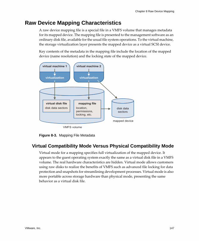
VMware, Inc. 147
Chapter 8 Raw Device Mapping
Raw Device Mapping CharacteristicsA raw device mapping file is a special file in a VMFS volume that manages metadata for its mapped device. The mapping file is presented to the management software as an ordinary disk file, available for the usual file system operations. To the virtual machine, the storage virtualization layer presents the mapped device as a virtual SCSI device.
Key contents of the metadata in the mapping file include the location of the mapped device (name resolution) and the locking state of the mapped device.
Figure 8-3. Mapping File Metadata
Virtual Compatibility Mode Versus Physical Compatibility ModeVirtual mode for a mapping specifies full virtualization of the mapped device. It appears to the guest operating system exactly the same as a virtual disk file in a VMFS volume. The real hardware characteristics are hidden. Virtual mode allows customers using raw disks to realize the benefits of VMFS such as advanced file locking for data protection and snapshots for streamlining development processes. Virtual mode is also more portable across storage hardware than physical mode, presenting the same behavior as a virtual disk file.
disk datasectors
VMFS volume
virtual machine 1
virtualization
mapped device
virtual machine 2
virtualization
disk data sectorsvirtual disk file
location, permissions, locking, etc.
mapping file
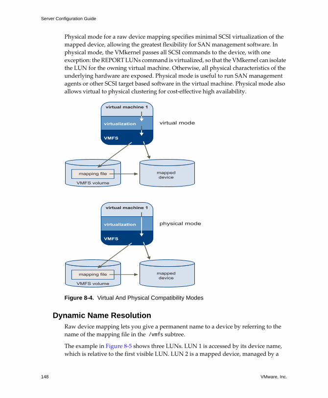
Server Configuration Guide
148 VMware, Inc.
Physical mode for a raw device mapping specifies minimal SCSI virtualization of the mapped device, allowing the greatest flexibility for SAN management software. In physical mode, the VMkernel passes all SCSI commands to the device, with one exception: the REPORT LUNs command is virtualized, so that the VMkernel can isolate the LUN for the owning virtual machine. Otherwise, all physical characteristics of the underlying hardware are exposed. Physical mode is useful to run SAN management agents or other SCSI target based software in the virtual machine. Physical mode also allows virtual to physical clustering for cost‐effective high availability.
Figure 8-4. Virtual And Physical Compatibility Modes
Dynamic Name ResolutionRaw device mapping lets you give a permanent name to a device by referring to the name of the mapping file in the /vmfs subtree.
The example in Figure 8‐5 shows three LUNs. LUN 1 is accessed by its device name, which is relative to the first visible LUN. LUN 2 is a mapped device, managed by a
VMFS volume
mappeddevice
mapping file
virtual machine 1
VMFS
virtualization virtual mode
VMFS volume
mappeddevice
mapping file
virtual machine 1
VMFS
virtualization physical mode
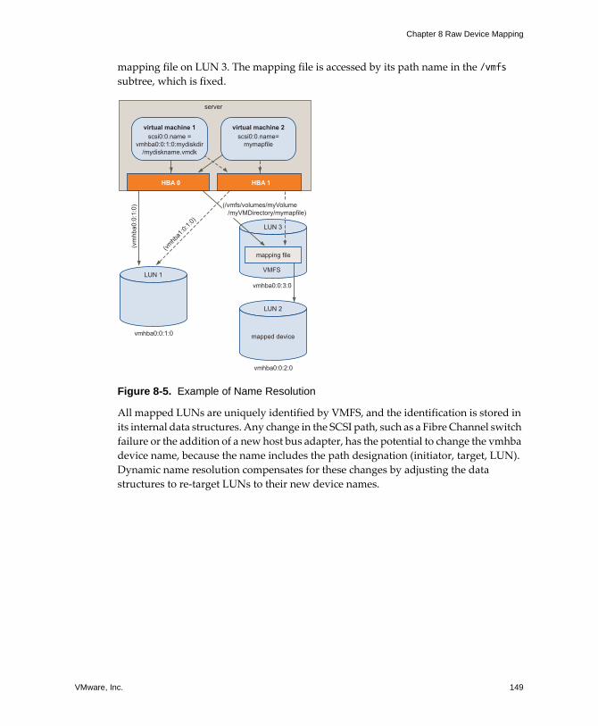
VMware, Inc. 149
Chapter 8 Raw Device Mapping
mapping file on LUN 3. The mapping file is accessed by its path name in the /vmfs subtree, which is fixed.
Figure 8-5. Example of Name Resolution
All mapped LUNs are uniquely identified by VMFS, and the identification is stored in its internal data structures. Any change in the SCSI path, such as a Fibre Channel switch failure or the addition of a new host bus adapter, has the potential to change the vmhba device name, because the name includes the path designation (initiator, target, LUN). Dynamic name resolution compensates for these changes by adjusting the data structures to re‐target LUNs to their new device names.
LUN 3
VMFS
mapping file
(vm
hba0
:0:1
:0)
(vmhb
a1:0:
1:0)
(/vmfs/volumes/myVolume /myVMDirectory/mymapfile)
LUN 2
mapped device
LUN 1
vmhba0:0:1:0
vmhba0:0:3:0
vmhba0:0:2:0
HBA 0 HBA 1
server
virtual machine 1scsi0:0.name =
vmhba0:0:1:0:mydiskdir/mydiskname.vmdk
virtual machine 2scsi0:0.name=
mymapfile
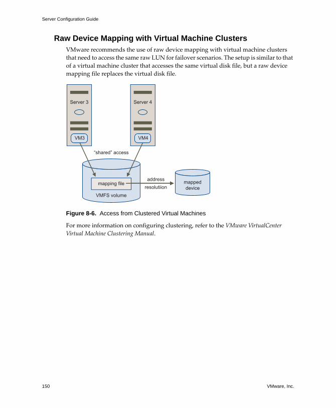
Server Configuration Guide
150 VMware, Inc.
Raw Device Mapping with Virtual Machine ClustersVMware recommends the use of raw device mapping with virtual machine clusters that need to access the same raw LUN for failover scenarios. The setup is similar to that of a virtual machine cluster that accesses the same virtual disk file, but a raw device mapping file replaces the virtual disk file.
Figure 8-6. Access from Clustered Virtual Machines
For more information on configuring clustering, refer to the VMware VirtualCenter Virtual Machine Clustering Manual.
addressresolutiion
Server 4Server 3
VMFS volume
“shared” access
VM4VM3
mappeddevice
mapping file
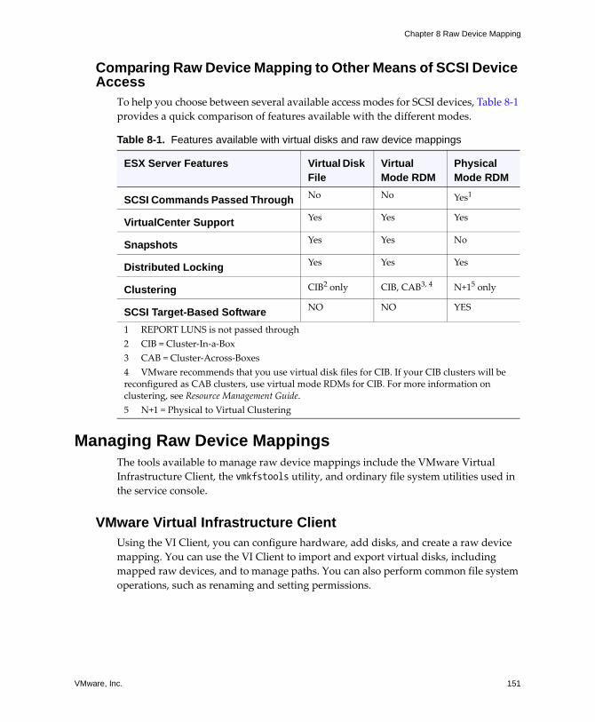
VMware, Inc. 151
Chapter 8 Raw Device Mapping
Comparing Raw Device Mapping to Other Means of SCSI Device Access
To help you choose between several available access modes for SCSI devices, Table 8‐1 provides a quick comparison of features available with the different modes.
Managing Raw Device MappingsThe tools available to manage raw device mappings include the VMware Virtual Infrastructure Client, the vmkfstools utility, and ordinary file system utilities used in the service console.
VMware Virtual Infrastructure Client Using the VI Client, you can configure hardware, add disks, and create a raw device mapping. You can use the VI Client to import and export virtual disks, including mapped raw devices, and to manage paths. You can also perform common file system operations, such as renaming and setting permissions.
Table 8-1. Features available with virtual disks and raw device mappings
ESX Server Features Virtual Disk File
Virtual Mode RDM
Physical Mode RDM
SCSI Commands Passed Through No No Yes1
VirtualCenter Support Yes Yes Yes
Snapshots Yes Yes No
Distributed Locking Yes Yes Yes
Clustering CIB2 only CIB, CAB3, 4 N+15 only
SCSI Target-Based Software NO NO YES
1 REPORT LUNS is not passed through2 CIB = Cluster‐In‐a‐Box3 CAB = Cluster‐Across‐Boxes4 VMware recommends that you use virtual disk files for CIB. If your CIB clusters will be reconfigured as CAB clusters, use virtual mode RDMs for CIB. For more information on clustering, see Resource Management Guide.5 N+1 = Physical to Virtual Clustering
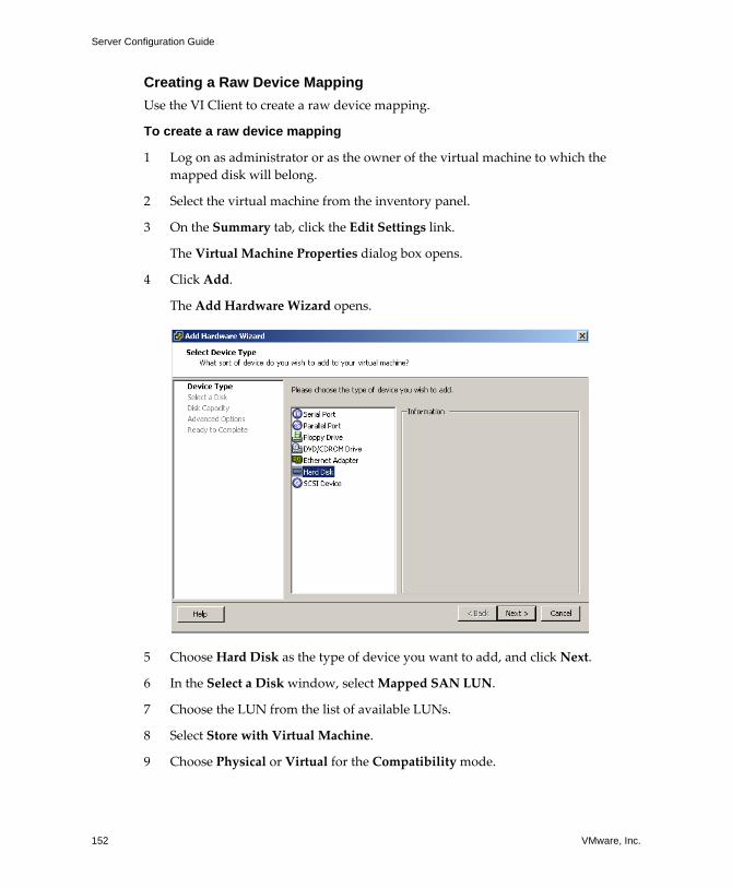
Server Configuration Guide
152 VMware, Inc.
Creating a Raw Device MappingUse the VI Client to create a raw device mapping.
To create a raw device mapping
1 Log on as administrator or as the owner of the virtual machine to which the mapped disk will belong.
2 Select the virtual machine from the inventory panel.
3 On the Summary tab, click the Edit Settings link.
The Virtual Machine Properties dialog box opens.
4 Click Add.
The Add Hardware Wizard opens.
5 Choose Hard Disk as the type of device you want to add, and click Next.
6 In the Select a Disk window, select Mapped SAN LUN.
7 Choose the LUN from the list of available LUNs.
8 Select Store with Virtual Machine.
9 Choose Physical or Virtual for the Compatibility mode.
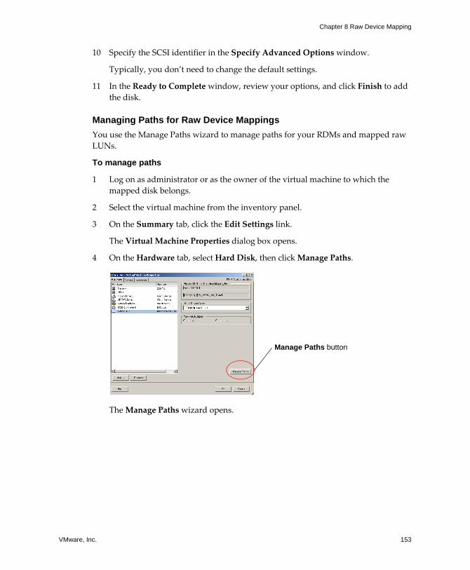
VMware, Inc. 153
Chapter 8 Raw Device Mapping
10 Specify the SCSI identifier in the Specify Advanced Options window.
Typically, you don�t need to change the default settings.
11 In the Ready to Complete window, review your options, and click Finish to add the disk.
Managing Paths for Raw Device MappingsYou use the Manage Paths wizard to manage paths for your RDMs and mapped raw LUNs.
To manage paths
1 Log on as administrator or as the owner of the virtual machine to which the mapped disk belongs.
2 Select the virtual machine from the inventory panel.
3 On the Summary tab, click the Edit Settings link.
The Virtual Machine Properties dialog box opens.
4 On the Hardware tab, select Hard Disk, then click Manage Paths.
The Manage Paths wizard opens.
Manage Paths button
Server Configuration Guide
154 VMware, Inc.
5 Use the Manage Paths wizard to enable or disable your paths, set multipathing policy, and specify the preferred path.
Follow these procedures:
! �To set the multipathing policy� on page 136
! �To disable a path� on page 137
! �To enable a path� on page 138
! �To set the preferred path� on page 138
The vmkfstools UtilityThe vmkfstools command line utility can be used in the service console to do many of the same operations available through the VI Client. Typical operations applicable to raw device mappings are the commands to create a mapping, to query mapping information such as the name and identification of the mapped device, and to import or export a virtual disk.
For more information, see �Using vmkfstools� on page 275.
File System Operations Most common file system operations done in the service console can be applied to raw device mappings.
ls -l
The ls command with the -l option shows the file name and permissions of the mapping file, while showing the length of the mapped device.
du
Similarly, the du command shows the space used by the mapped device, rather than the mapping file.
mv
The mv command renames the mapping file, but doesn�t affect the mapped device.
VMware, Inc. 155
Chapter 8 Raw Device Mapping
cp
You can use the cp command to copy the contents of a mapped device, but it does not work in reverse. You can�t use it to copy a virtual disk file to a mapped device. Instead, you can use the vmkfstools command.
dd
You can use the dd command to copy data into or out of a mapped device. However, VMware recommends that you use vmkfstools import and export commands to do this in an efficient manner.

Server Configuration Guide
156 VMware, Inc.

VMware, Inc. 157
Security

Server Configuration Guide
158 VMware, Inc.
VMware, Inc. 159
CHAPTER 9 Security for ESX Server Systems
ESX Server has been developed with a focus on strong security. This section provides you with an overview of how VMware ensures security in the ESX Server environment, addressing system architecture from a security standpoint and giving you a list of additional security resources.
This chapter contains the following sections:
! �ESX Server Architecture and Security Features� on page 160
! �Security Resources and Information� on page 171
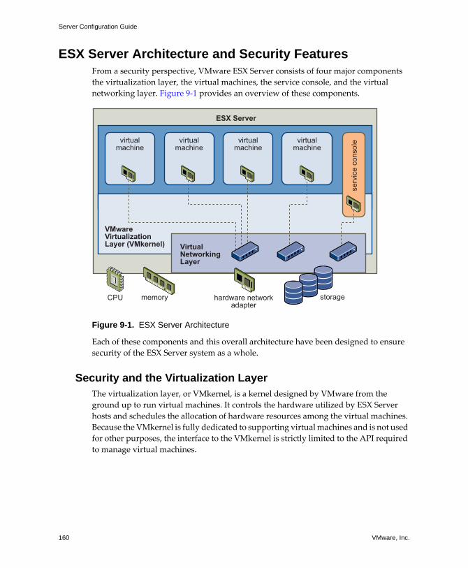
Server Configuration Guide
160 VMware, Inc.
ESX Server Architecture and Security FeaturesFrom a security perspective, VMware ESX Server consists of four major components the virtualization layer, the virtual machines, the service console, and the virtual networking layer. Figure 9‐1 provides an overview of these components.
Figure 9-1. ESX Server Architecture
Each of these components and this overall architecture have been designed to ensure security of the ESX Server system as a whole.
Security and the Virtualization LayerThe virtualization layer, or VMkernel, is a kernel designed by VMware from the ground up to run virtual machines. It controls the hardware utilized by ESX Server hosts and schedules the allocation of hardware resources among the virtual machines. Because the VMkernel is fully dedicated to supporting virtual machines and is not used for other purposes, the interface to the VMkernel is strictly limited to the API required to manage virtual machines.
CPU memory storagehardware networkadapter
ESX Server
virtualmachine
virtualmachine
virtualmachine
virtualmachine
VMware Virtualization Layer (VMkernel) Virtual
NetworkingLayer
serv
ice
cons
ole
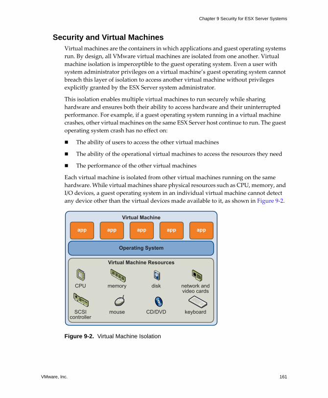
VMware, Inc. 161
Chapter 9 Security for ESX Server Systems
Security and Virtual MachinesVirtual machines are the containers in which applications and guest operating systems run. By design, all VMware virtual machines are isolated from one another. Virtual machine isolation is imperceptible to the guest operating system. Even a user with system administrator privileges on a virtual machine�s guest operating system cannot breach this layer of isolation to access another virtual machine without privileges explicitly granted by the ESX Server system administrator.
This isolation enables multiple virtual machines to run securely while sharing hardware and ensures both their ability to access hardware and their uninterrupted performance. For example, if a guest operating system running in a virtual machine crashes, other virtual machines on the same ESX Server host continue to run. The guest operating system crash has no effect on:
! The ability of users to access the other virtual machines
! The ability of the operational virtual machines to access the resources they need
! The performance of the other virtual machines
Each virtual machine is isolated from other virtual machines running on the same hardware. While virtual machines share physical resources such as CPU, memory, and I/O devices, a guest operating system in an individual virtual machine cannot detect any device other than the virtual devices made available to it, as shown in Figure 9‐2.
Figure 9-2. Virtual Machine Isolation
CPU memory disk network andvideo cards
SCSIcontroller
mouse CD/DVD keyboard
Virtual Machine
Operating System
Virtual Machine Resources
app app app app app
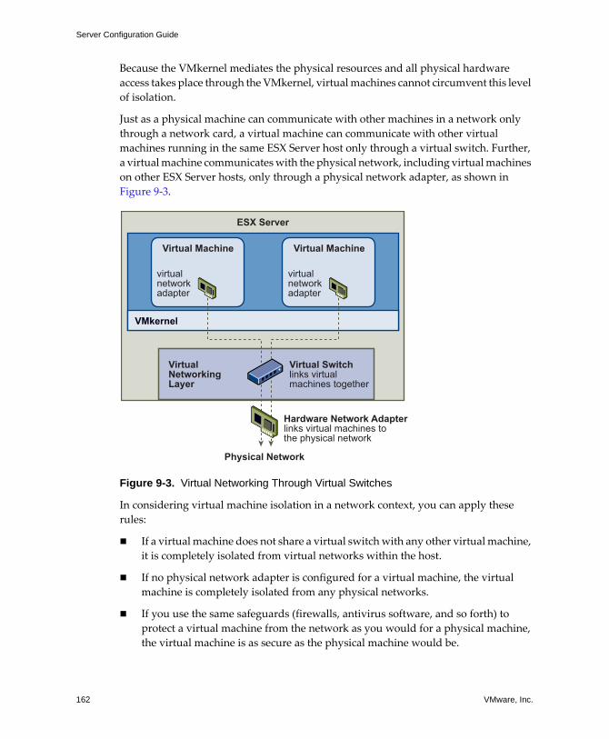
Server Configuration Guide
162 VMware, Inc.
Because the VMkernel mediates the physical resources and all physical hardware access takes place through the VMkernel, virtual machines cannot circumvent this level of isolation.
Just as a physical machine can communicate with other machines in a network only through a network card, a virtual machine can communicate with other virtual machines running in the same ESX Server host only through a virtual switch. Further, a virtual machine communicates with the physical network, including virtual machines on other ESX Server hosts, only through a physical network adapter, as shown in Figure 9‐3.
Figure 9-3. Virtual Networking Through Virtual Switches
In considering virtual machine isolation in a network context, you can apply these rules:
! If a virtual machine does not share a virtual switch with any other virtual machine, it is completely isolated from virtual networks within the host.
! If no physical network adapter is configured for a virtual machine, the virtual machine is completely isolated from any physical networks.
! If you use the same safeguards (firewalls, antivirus software, and so forth) to protect a virtual machine from the network as you would for a physical machine, the virtual machine is as secure as the physical machine would be.
Hardware Network Adapterlinks virtual machines tothe physical network
Physical Network
virtualnetworkadapter
ESX Server
Virtual Machine
virtualnetworkadapter
Virtual Machine
VMkernel
VirtualNetworkingLayer
Virtual Switchlinks virtualmachines together
VMware, Inc. 163
Chapter 9 Security for ESX Server Systems
You can further protect virtual machines by setting up resource reservations and limits on the ESX Server host. For example, through the fine‐grained resource controls available in ESX Server, you can configure a virtual machine so that it always gets at least ten percent of the ESX Server host�s CPU resources, but never more than twenty percent.
Resource reservations and limits protect virtual machines from performance degradation if another virtual machine tries to consume too many resources on shared hardware. For example, if one of the virtual machines on an ESX Server host is incapacitated by a denial‐of‐service (DOS) or distributed denial‐of‐service (DDOS) attack, a resource limit on that machine prevents the attack from taking up so many hardware resources that the other virtual machines are also affected. Similarly, a resource reservation on each of the virtual machines ensures that, in the event of high resource demands by the virtual machine targeted by the DOS attack, all the other virtual machines still have enough resources to operate.
By default, ESX server imposes a form of resource reservation by applying a distribution algorithm that divides the available host resources equally among the virtual machines while keeping a certain percentage of resources for use by other system components such as the service console. This default behavior provides a degree of natural protection from DOS and DDOS attacks. You set specific resource reservations and limits on an individual basis if you want to customize the default behavior so that the distribution isn�t equal across the vitual machine configuration. For a discussion of how to manage resource allocation for virtual machines, see the Resource Management Guide.
Security and the Service ConsoleThe ESX Server 3.0 service console is a limited distribution of Linux based on Red Hat Enterprise Linux 3, Update 6 (RHEL 3 U6). The service console provides an execution environment to monitor and administer the entire ESX Server host.
If the service console is compromised in certain ways, the virtual machines it interacts with might also be compromised. To minimize the risk of an attack through the service console, VMware protects the service console with a firewall. For information about this firewall, see �Service Console Firewall Configuration� on page 236.
In addition to implementing the service console firewall, here are some of the other ways VMware mitigates risks to the service console:
! ESX Server runs only services essential to managing its functions, and the distribution is limited to the features required to run ESX Server.
Server Configuration Guide
164 VMware, Inc.
! By default, ESX Server is installed with a high security setting, which means that all outbound ports are closed and the only inbound ports that are open are those required for interactions with clients such as the VMware Virtual Infrastructure Client. VMware recommends that you keep this security setting unless the service console is connected to a trusted network.
! By default, all ports not specifically required for management access to the service console are closed. You must specifically open ports if you need additional services.
! All communications from clients are encrypted through SSL by default. The SSL connection uses 256‐bit AES block encryption and 1024‐bit RSA key encryption.
! The Tomcat Web service, used internally by ESX Server to support access to the service console by Web clients like VMware Virtual Infrastructure Web Access, has been modified to run only those functions required for administration and monitoring by a Web client. As a result, ESX Server is not vulnerable to the Tomcat security issues reported in broader usage.
! VMware monitors all security alerts that could affect service console security and, if needed, issues a security patch, as it would for any other security vulnerability that could affect ESX Server hosts. VMware provides security patches for RHEL 3 U6 and later as they become available
! Insecure services such as FTP and Telnet are not installed and the ports for these services are closed by default. Because more secure services such as SSH and SFTP are easily available, always avoid using these insecure services in favor of their safer alternatives. If you must use insecure services and have implemented sufficient protection for the service console, you must explicitly open ports to support them.
! The number of applications that use a setuid or setgid flag has been minimized, and you can disable any setuid or setgid application that is optional to ESX Server operation. For information on required and options setuid and setgid applications, see �setuid and setgid Applications� on page 249.
For details on these security measures and other service console security recommendations, see �Service Console Security� on page 233.
While you can install and run certain types of programs designed for RHEL 3 U6 in the service console, this usage can have serious security consequences and is not supported unless VMware explicitly states that it is. If a security vulnerability is discovered in a
VMware, Inc. 165
Chapter 9 Security for ESX Server Systems
supported configuration, VMware proactively notifies all customers with valid Support and Subscription contracts and provides all necessary patches.
NOTE Some security advisories issued by Red Hat don�t apply to the ESX Server environment. If this is the case, VMware does not provide notification or patches.
To learn more about VMware�s policies on security patches for supported programs as well as its policies on unsupported software, see �Security Resources and Information� on page 171.
Security and the Virtual Networking LayerThe virtual networking layer consists of the virtual network devices through which virtual machines and the service console interface with the rest of the network. ESX Server relies on the connectivity layer to support communications between virtual machines and their users. In addition, ESX Server hosts use the connectivity layer to communicate with iSCSI SANs, NAS storage, and so forth. The connectivity layer includes virtual network adapters and the virtual switches.
The methods you use to secure a virtual machine network depend on which guest operating system is installed, whether the virtual machines operate in a trusted environment, and a variety of other factors. Virtual switches provide a substantial degree of protection when used with other common security practices such as installing firewalls. ESX Server also supports IEEE 802.1q VLANs, which you can use to further protect the virtual machine network, service console, or storage configuration. VLANs let you segment a physical network so that two machines on the same physical network cannot send packets to or receive packets from each other unless they are on the same VLAN.
You can get a sense of how to use virtual switches to implement security tools like DMZs and configure virtual machines on different networks within the same ESX Server host by reviewing the following examples.
NOTE For a specific discussion of how virtual switches and VLANs help safeguard the virtual machine network and a discussion of other security recommendations for virtual machine networks, see �Securing Virtual Machines with VLANs� on page 188.
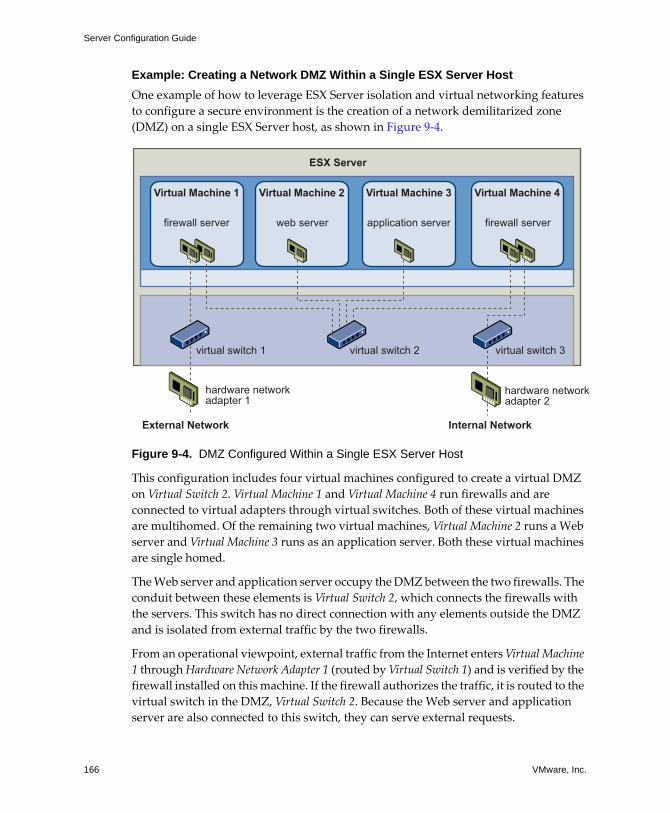
Server Configuration Guide
166 VMware, Inc.
Example: Creating a Network DMZ Within a Single ESX Server Host One example of how to leverage ESX Server isolation and virtual networking features to configure a secure environment is the creation of a network demilitarized zone (DMZ) on a single ESX Server host, as shown in Figure 9‐4.
Figure 9-4. DMZ Configured Within a Single ESX Server Host
This configuration includes four virtual machines configured to create a virtual DMZ on Virtual Switch 2. Virtual Machine 1 and Virtual Machine 4 run firewalls and are connected to virtual adapters through virtual switches. Both of these virtual machines are multihomed. Of the remaining two virtual machines, Virtual Machine 2 runs a Web server and Virtual Machine 3 runs as an application server. Both these virtual machines are single homed.
The Web server and application server occupy the DMZ between the two firewalls. The conduit between these elements is Virtual Switch 2, which connects the firewalls with the servers. This switch has no direct connection with any elements outside the DMZ and is isolated from external traffic by the two firewalls.
From an operational viewpoint, external traffic from the Internet enters Virtual Machine 1 through Hardware Network Adapter 1 (routed by Virtual Switch 1) and is verified by the firewall installed on this machine. If the firewall authorizes the traffic, it is routed to the virtual switch in the DMZ, Virtual Switch 2. Because the Web server and application server are also connected to this switch, they can serve external requests.
hardware networkadapter 1
External Network Internal Network
hardware networkadapter 2
ESX Server
Virtual Machine 1
firewall server web server application server firewall server
virtual switch 1 virtual switch 2 virtual switch 3
Virtual Machine 2 Virtual Machine 3 Virtual Machine 4

VMware, Inc. 167
Chapter 9 Security for ESX Server Systems
Virtual Switch 2 is also connected to Virtual Machine 4. This virtual machine provides a firewall between the DMZ and the internal corporate network. This firewall filters packets from the Web server and application server. If a packet is verified, it is routed to Hardware Network Adapter 2 through Virtual Switch 3. Hardware Network Adapter 2 is connected to the internal corporate network.
When creating a DMZ within a single ESX Server, you can use fairly lightweight firewalls. While a virtual machine in this configuration cannot exert direct control over another virtual machine or access its memory, all the virtual machines are still connected through a virtual network, and this network could be leveraged for virus propagation or targeted for other types of attacks. You can consider the virtual machines in the DMZ neither more nor less secure than separate physical machines connected to the same network.
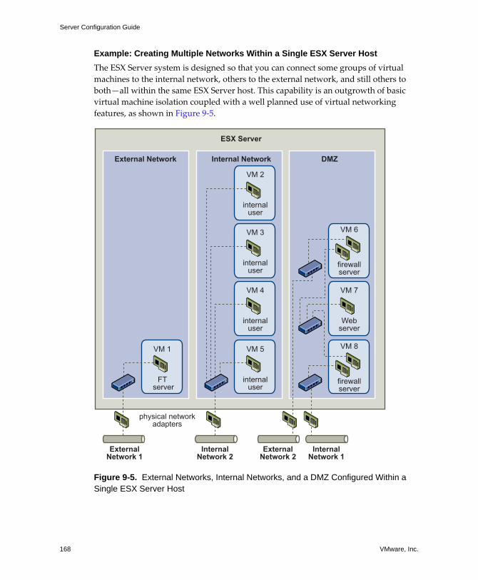
Server Configuration Guide
168 VMware, Inc.
Example: Creating Multiple Networks Within a Single ESX Server HostThe ESX Server system is designed so that you can connect some groups of virtual machines to the internal network, others to the external network, and still others to both�all within the same ESX Server host. This capability is an outgrowth of basic virtual machine isolation coupled with a well planned use of virtual networking features, as shown in Figure 9‐5.
Figure 9-5. External Networks, Internal Networks, and a DMZ Configured Within a Single ESX Server Host
physical networkadapters
ExternalNetwork 1
InternalNetwork 2
ExternalNetwork 2
InternalNetwork 1
ESX Server
VM 2
internaluser
VM 3
internaluser
VM 4
internaluser
VM 5
internaluser
VM 6
firewallserver
VM 7
Webserver
VM 8
firewallserver
VM 1
FT server
Internal NetworkExternal Network DMZ
VMware, Inc. 169
Chapter 9 Security for ESX Server Systems
Here, the system administrator configured an ESX Server host into three distinct virtual machine zones, each serving a unique function:
! FTP server � Virtual Machine 1 is configured with FTP software and acts as a holding area for data sent to and from outside resources such as forms and collateral localized by a vendor.
This virtual machine is associated with an external network only. It has its own virtual switch and physical network adapter that connect it to External Network 1. This network is dedicated to servers that the company uses to receive data from outside sources. For example, the company uses External Network 1 to receive FTP traffic from vendors and allow vendors access to data stored on externally available servers though FTP. In addition to servicing Virtual Machine 1, External Network 1 services FTP servers configured on different ESX Server hosts throughout the site.
Because Virtual Machine 1 doesn�t share a virtual switch or physical network adapter with any virtual machines in the host, the other resident virtual machines cannot transmit packets to or receive packets from Virtual Machine 1�s network. This prevents sniffing attacks, which require sending network traffic to the victim. More importantly, an attacker cannot leverage the natural vulnerability of FTP to access any of the host�s other virtual machines.
! Internal virtual machines � Virtual Machines 2 � 5 are reserved for internal use. These virtual machines process and store company‐private data such as medical records, legal settlements, and fraud investigations. As a result, the system administrators must ensure the highest level of protection for these virtual machines.
These virtual machines connect to Internal Network 2 through their own virtual switch and network adapter. Internal Network 2 is reserved for internal use by personnel such as claims processors, in‐house lawyers, or adjustors.
Virtual Machines 2 � 5 can communicate with one another through the virtual switch and with internal virtual machines elsewhere on Internal Network 2 through the physical network adapter. They cannot communicate with externally‐facing machines. As with the FTP server, these virtual machines cannot send packets to or receive packets from the other virtual machines� networks. Similarly, the host�s other virtual machines cannot send packets to or receive packets from Virtual Machines 2 � 5.
! DMZ � Virtual Machines 6 � 8 are configured as a DMZ that the marketing group uses to publish the company�s external Web site.
This group of virtual machines is associated with External Network 2 and Internal Network 1. The company uses External Network 2 to support the Web servers used
Server Configuration Guide
170 VMware, Inc.
by the marketing and financial department to host the corporate Web site and other Web facilities that it hosts to outside users. Internal Network 1 is the conduit that the marketing department uses to publish web pages to the corporate Web site, post downloads, and maintain services like user forums.
Because these networks are separate from External Network 1 and Internal Network 2 and the virtual machines have no shared points of contact (switches or adapters), there is no risk of attack to or from the FTP Server or the internal virtual machine group.
For an example of configuring a DMZ with virtual machines, see �Example: Creating a Network DMZ Within a Single ESX Server Host� on page 166.
By capitalizing on virtual machine isolation, correctly configuring virtual switches, and maintaining network separation, the system administrator can house all three virtual machine zones in the same ESX Server host and be confident that there will be no data or resource breaches.
The company enforces isolation among the virtual machine groups by using multiple internal and external networks and making sure that the virtual switches and physical network adapters for each group are completely separate from those of other groups.
Because none of the virtual switches straddle virtual machine zones, the system administrator succeeds in eliminating the risk of packet leakage from one zone to another. A virtual switch, by design, cannot leak packets directly to another virtual switch. The only way for packets to travel from one virtual switch to another is if:
! The virtual switches are connected to the same physical LAN.
! The virtual switches connect to a common virtual machine, which could then be used to transmit packets.
Neither of these conditions occur in sample configuration. If the system administrator wants to verify that no common virtual switch paths exist, he or she can check for possible shared points of contact by reviewing the network switch layout in the VI Client or VI Web Access. For information on the virtual switch layout, see �Virtual Switches� on page 9.
To safeguard the virtual machines� resources, the system administrator lowers the risk of DOS and DDOS attacks by configuring a resource reservation and limit for each virtual machine. The system administrator further protects the ESX Server host and virtual machines by installing software firewalls at the front and back ends of the DMZ, ensuring that the ESX Server host is behind a physical firewall, and configuring the service console and networked storage resources so that each has its own virtual switch.
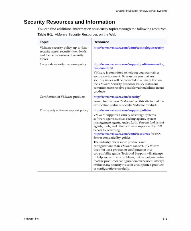
VMware, Inc. 171
Chapter 9 Security for ESX Server Systems
Security Resources and InformationYou can find additional information on security topics through the following resources.Table 9-1. VMware Security Resources on the Web
Topic ResourceVMware security policy, up‐to‐date security alerts, security downloads, and focus discussions of security topics
http://www.vmware.com/vmtn/technology/security
Corporate security response policy http://www.vmware.com/support/policies/security_response.html VMware is committed to helping you maintain a secure environment. To reassure you that any security issues will be corrected in a timely fashion, the VMware Security Response Policy states our commitment to resolve possible vulnerabilities in our products.
Certification of VMware products http://www.vmware.com/security/ Search for the term �VMware� on this site to find the certification status of specific VMware products.
Third‐party software support policy http://www.vmware.com/support/policies VMware supports a variety of storage systems, software agents such as backup agents, system management agents, and so forth. You can find lists of agents, tools, and other software supported by ESX Server by searching http://www.vmware.com/vmtn/resources for ESX Server compatibility guides. The industry offers more products and configurations than VMware can test. If VMware does not list a product or configuration in a compatibility guide, Technical Support will attempt to help you with any problems, but cannot guarantee that the product or configuration can be used. Always evaluate any security risks for unsupported products or configurations carefully.

Server Configuration Guide
172 VMware, Inc.
VMware, Inc. 173
CHAPTER 10 Securing an ESX Server Configuration
This chapter describes measures you can take to promote a secure environment for your ESX Server hosts, virtual machines, and iSCSI SANs. The discussion focuses on network configuration planning from a security perspective and the steps you can take to protect the components in your configuration from attack.
This chapter covers the following topics:
! �Securing the Network with Firewalls� on page 174
! �Securing Virtual Machines with VLANs� on page 188
! �Securing iSCSI Storage� on page 197
Server Configuration Guide
174 VMware, Inc.
Securing the Network with FirewallsSecurity administrators use firewalls to safeguard the network or selected components within the network from intrusion. Firewalls control access to devices within their perimeter by closing all communication pathways except for those that the administrator explicitly or implicitly designates as authorized, thus preventing unauthorized use of the devices. The pathways, or ports, that administrators open in the firewall allow traffic between devices on different sides of the firewall.
In a virtual machine environment, you can plan your layout for firewalls between:
! Physical machines such as VirtualCenter Management Server hosts and ESX Server hosts.
! One virtual machine and another�for example, between a virtual machine acting as an external Web server and a virtual machine connected to your company�s internal network.
! A physical machine and a virtual machine as when you place a firewall between a physical network adapter card and a virtual machine.
How you utilize firewalls in an ESX Server configuration is based on how you plan to use the network and how secure any given component needs to be. For example, if you create a virtual network where each virtual machine is dedicated to running a different benchmark test suite for the same department, the risk of unwanted access from one virtual machine to the next is minimal. Hence, you have little need to set up the configuration so that firewalls are present between the virtual machines. However, to prevent interruption of a test run from an outside host, you might set up the configuration so that a firewall is present at the entry point of the virtual network to protect the entire set of virtual machines.

VMware, Inc. 175
Chapter 10 Securing an ESX Server Configuration
This section shows firewall placement for configurations with and without VirtualCenter. It also provides information on the firewall ports required for ESX Server systems. The section covers the following topics:
! �Firewalls for Configurations with a VirtualCenter Server� on page 176
! �Firewalls for Configurations Without a VirtualCenter Server� on page 179
! �TCP and UDP Ports for Management Access� on page 180
! �Connecting to VirtualCenter Server Through a Firewall� on page 182
! �Connecting to the Virtual Machine Console Through a Firewall� on page 183
! �Connecting ESX Server Hosts Through Firewalls� on page 184
! �Opening Firewall Ports for Supported Services and Management Agents� on page 185
For information on the service console firewall, see �Service Console Firewall Configuration� on page 236. To configure the firewall and port settings during installation, see the Installation and Upgrade Guide.
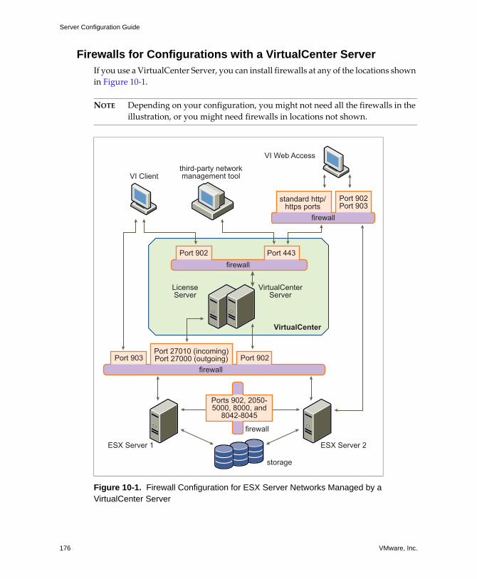
Server Configuration Guide
176 VMware, Inc.
Firewalls for Configurations with a VirtualCenter ServerIf you use a VirtualCenter Server, you can install firewalls at any of the locations shown in Figure 10‐1.
NOTE Depending on your configuration, you might not need all the firewalls in the illustration, or you might need firewalls in locations not shown.
Figure 10-1. Firewall Configuration for ESX Server Networks Managed by a VirtualCenter Server
VirtualCenterServer
ESX Server 1 ESX Server 2
VirtualCenter
LicenseServer
VI Web Access
VI Clientthird-party networkmanagement tool
storage
firewall
standard http/https ports
Ports 902, 2050-5000, 8000, and
8042-8045
Port 902Port 903
Port 27010 (incoming)Port 27000 (outgoing) Port 902Port 903
Port 902 Port 443firewall
firewall
firewall
VMware, Inc. 177
Chapter 10 Securing an ESX Server Configuration
Networks configured with a VirtualCenter Server can receive communications through several types of clients: the VI Client, VI Web Access, or third‐party network management clients that use the SDK to interface with the host. During normal operation, VirtualCenter listens for data from its managed hosts and clients on designated ports. VirtualCenter also assumes that its managed hosts listen for data from VirtualCenter on designated ports. If a firewall is present between any of these elements, you must ensure that there are open ports in the firewall to support data transfer.
If you access ESX Server hosts through a VirtualCenter Server, you typically protect the VirtualCenter Server using a firewall. This firewall provides basic protection for your network. Whether this firewall lies between the clients and the VirtualCenter Server or both the VirtualCenter Server and the clients are behind the firewall depends on your deployment. The main thing is to ensure that a firewall is present at what you consider to be an entry point for the system as a whole.
You might also include firewalls at a variety of other access points in the network, depending on how you plan to use the network and how secure the various devices need to be. Select the locations for your firewalls based on the security risks that you�ve identified for your network configuration. The following is a list of firewall locations common to ESX Server implementations. Many of the firewall locations in the list and illustration are optional.
! Between your Web browser and VI Web Access HTTP and HTTPS proxy server.
! Between the VI Client, VI Web Access, or a third‐party network management client and the VirtualCenter Server.
! If your users access virtual machines through the VI Client, between the VI Client and the ESX Server host. This connection is in addition to the connection between the VI Client and the VirtualCenter Server, and it requires a different port.
! If your users access virtual machines through a Web browser, between the Web browser and the ESX Server host. This connection is in addition to the connection between the VI Web Access Client and VirtualCenter Server, and it requires different ports.
! Between the license server and either the VirtualCenter Server or the ESX Server host. Typically, in configurations that include a VirtualCenter Server, the license server runs on the same physical machine as does the VirtualCenter Server. In this case, the license server connects to the ESX Server network through a firewall, running in parallel with the VirtualCenter Server but using different ports.
In some configurations, you might use an external license server�for example, if your company wants to control all licenses through a single, dedicated appliance.
Server Configuration Guide
178 VMware, Inc.
Here, you would connect the license server to the VirtualCenter Server through a firewall between these two servers.
Regardless of how you set up the license server connection, the ports you use for license traffic are the same. For information on licensing, see the Installation and Upgrade Guide.
! Between the VirtualCenter Server and the ESX Server hosts.
! Between the ESX Server hosts in your network. Although traffic between ESX Server hosts is usually considered trusted, you can add firewalls between your ESX Server hosts if you are concerned about security breaches from machine to machine.
If you add firewalls between ESX Server hosts and plan to migrate virtual machines between the servers, perform cloning, or use VMotion, you must also open ports in any firewall that divides the source host from the target hosts so that the source and targets can communicate.
! Between the ESX Server hosts and peripheral devices such as NFS storage. These ports are not specific to VMware, and you configure them according to the specifications for your network.
For information on the ports to open for these communications paths, see �TCP and UDP Ports for Management Access� on page 180.
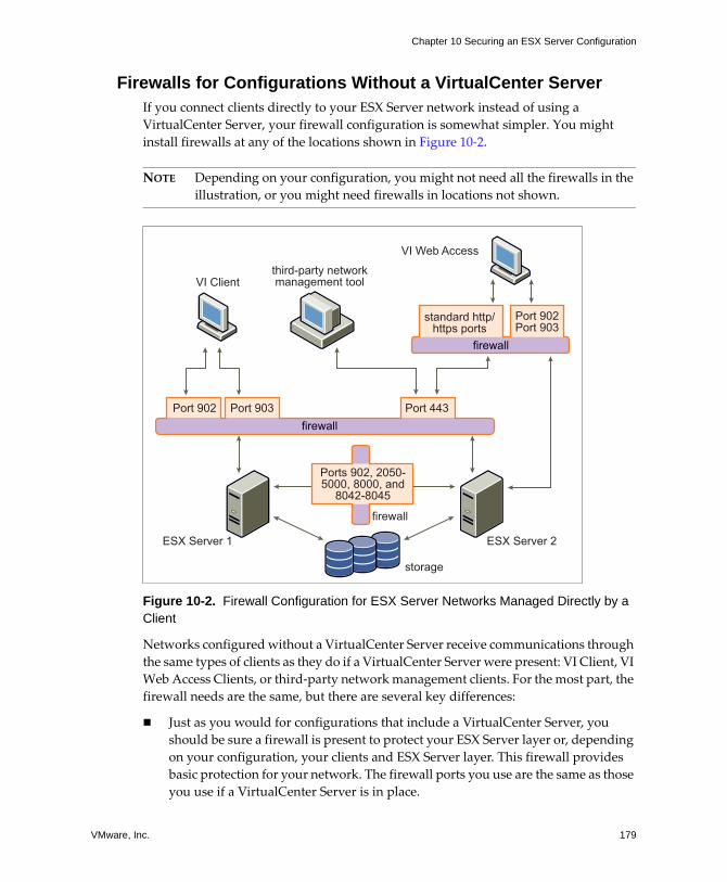
VMware, Inc. 179
Chapter 10 Securing an ESX Server Configuration
Firewalls for Configurations Without a VirtualCenter ServerIf you connect clients directly to your ESX Server network instead of using a VirtualCenter Server, your firewall configuration is somewhat simpler. You might install firewalls at any of the locations shown in Figure 10‐2.
NOTE Depending on your configuration, you might not need all the firewalls in the illustration, or you might need firewalls in locations not shown.
Figure 10-2. Firewall Configuration for ESX Server Networks Managed Directly by a Client
Networks configured without a VirtualCenter Server receive communications through the same types of clients as they do if a VirtualCenter Server were present: VI Client, VI Web Access Clients, or third‐party network management clients. For the most part, the firewall needs are the same, but there are several key differences:
! Just as you would for configurations that include a VirtualCenter Server, you should be sure a firewall is present to protect your ESX Server layer or, depending on your configuration, your clients and ESX Server layer. This firewall provides basic protection for your network. The firewall ports you use are the same as those you use if a VirtualCenter Server is in place.
ESX Server 1 ESX Server 2
VI Web Access
VI Clientthird-party networkmanagement tool
storage
firewall
standard http/https ports
Ports 902, 2050-5000, 8000, and
8042-8045
Port 902Port 903
Port 902 Port 903 Port 443
firewall
firewall
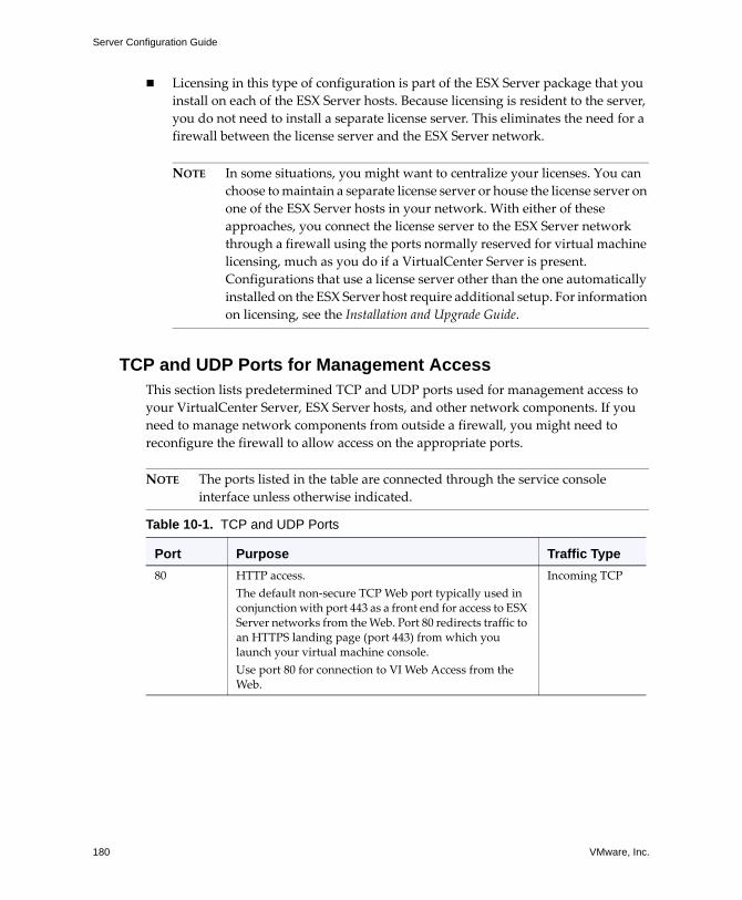
Server Configuration Guide
180 VMware, Inc.
! Licensing in this type of configuration is part of the ESX Server package that you install on each of the ESX Server hosts. Because licensing is resident to the server, you do not need to install a separate license server. This eliminates the need for a firewall between the license server and the ESX Server network.
NOTE In some situations, you might want to centralize your licenses. You can choose to maintain a separate license server or house the license server on one of the ESX Server hosts in your network. With either of these approaches, you connect the license server to the ESX Server network through a firewall using the ports normally reserved for virtual machine licensing, much as you do if a VirtualCenter Server is present. Configurations that use a license server other than the one automatically installed on the ESX Server host require additional setup. For information on licensing, see the Installation and Upgrade Guide.
TCP and UDP Ports for Management AccessThis section lists predetermined TCP and UDP ports used for management access to your VirtualCenter Server, ESX Server hosts, and other network components. If you need to manage network components from outside a firewall, you might need to reconfigure the firewall to allow access on the appropriate ports.
NOTE The ports listed in the table are connected through the service console interface unless otherwise indicated.
Table 10-1. TCP and UDP Ports
Port Purpose Traffic Type80 HTTP access.
The default non‐secure TCP Web port typically used in conjunction with port 443 as a front end for access to ESX Server networks from the Web. Port 80 redirects traffic to an HTTPS landing page (port 443) from which you launch your virtual machine console.Use port 80 for connection to VI Web Access from the Web.
Incoming TCP
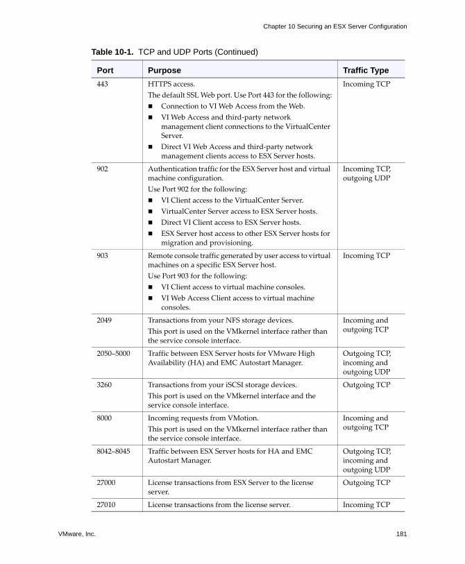
VMware, Inc. 181
Chapter 10 Securing an ESX Server Configuration
443 HTTPS access.The default SSL Web port. Use Port 443 for the following:! Connection to VI Web Access from the Web.! VI Web Access and third‐party network
management client connections to the VirtualCenter Server.
! Direct VI Web Access and third‐party network management clients access to ESX Server hosts.
Incoming TCP
902 Authentication traffic for the ESX Server host and virtual machine configuration. Use Port 902 for the following:! VI Client access to the VirtualCenter Server.! VirtualCenter Server access to ESX Server hosts.! Direct VI Client access to ESX Server hosts. ! ESX Server host access to other ESX Server hosts for
migration and provisioning.
Incoming TCP, outgoing UDP
903 Remote console traffic generated by user access to virtual machines on a specific ESX Server host.Use Port 903 for the following:! VI Client access to virtual machine consoles.! VI Web Access Client access to virtual machine
consoles.
Incoming TCP
2049 Transactions from your NFS storage devices.This port is used on the VMkernel interface rather than the service console interface.
Incoming and outgoing TCP
2050�5000 Traffic between ESX Server hosts for VMware High Availability (HA) and EMC Autostart Manager.
Outgoing TCP, incoming and outgoing UDP
3260 Transactions from your iSCSI storage devices.This port is used on the VMkernel interface and the service console interface.
Outgoing TCP
8000 Incoming requests from VMotion.This port is used on the VMkernel interface rather than the service console interface.
Incoming and outgoing TCP
8042�8045 Traffic between ESX Server hosts for HA and EMC Autostart Manager.
Outgoing TCP, incoming and outgoing UDP
27000 License transactions from ESX Server to the license server.
Outgoing TCP
27010 License transactions from the license server. Incoming TCP
Table 10-1. TCP and UDP Ports (Continued)
Port Purpose Traffic Type
Server Configuration Guide
182 VMware, Inc.
NOTE ESX Server and VirtualCenter use ports 8085, 8087, and 9080 internally. For ESX Server, ports 8085, 8087, and 9080 are protected because they don�t accept remote connections.
In addition to the TCP and UDP ports just discussed, you can configure other ports depending on your needs:
! You can use VirtualCenter to open ports for installed management agents and supported services such as SSH, NFS, and so forth. For information on configuring additional ports for these services, see �Opening Firewall Ports for Supported Services and Management Agents� on page 185.
! You can open ports in the service console firewall for other services and agents required for your network by running command line scripts. For more information, see �Service Console Firewall Configuration� on page 236.
Connecting to VirtualCenter Server Through a FirewallAs shown in Table 10‐1, the ports that VirtualCenter Server uses to listen for data transfer from its clients are 902 (VI Client) and 443 (other clients). If you have a firewall between your VirtualCenter Server and its clients, you must configure a connection through which the VirtualCenter Server can receive data from the clients.
To enable the VirtualCenter Server to receive data from a VI Client, open port 902 in the firewall to allow data transfer from the VI Client to the VirtualCenter Server. For connections between the VirtualCenter Server and VI Web Access Clients or third‐party clients working through the SDK, open port 443. Contact the firewall system administrator for additional information on configuring ports in a firewall.
If you are using the VI Client and don�t want to use port 902 as the port for the VI Client‐to‐VirtualCenter Server communication, you can switch to another port by changing the VirtualCenter settings in the VI Client. To learn how to change these settings, see the Virtual Infrastructure User�s Guide.

VMware, Inc. 183
Chapter 10 Securing an ESX Server Configuration
Connecting to the Virtual Machine Console Through a FirewallWhether you connect your client to ESX Server hosts through a VirtualCenter Server or use a direct connection to the ESX Server host, certain ports are required for user and administrator communication with virtual machine consoles. These ports support different client functions, interface with different layers within ESX Server, and use different authentication protocols. They are:
! Port 902 � The VirtualCenter Server uses this port to send data to the VirtualCenter managed hosts. Also, the VI Client, when connected directly to an ESX Server host, uses this port to support any management functions related to the server and its virtual machines. Port 902 is the port that the VirtualCenter Server and the VI Client assume is available when sending data to the ESX Server host. VMware doesn�t support configuring a different port for these connections.
Port 902 connects the VirtualCenter Server or client to the ESX Server host through the VMware Authorization Daemon (vmware-authd) running in the service console. The authorization daemon multiplexes port 902 data to the VMware Host Agent (vmware-hostd) for processing.
! Port 443 � The VI Web Access Client and SDK use this port to send data to the VirtualCenter managed hosts. Also, the VI Web Access Client and SDK, when connected directly to an ESX Server host, use this port to support any management functions related to the server and its virtual machines. Port 443 is the port that the VI Web Access Client and the SDK assume is available when sending data to the ESX Server host. VMware doesn�t support configuring a different port for these connections.
Port 443 connects the VI Web Access Client or third‐party network management client to the ESX Server host through the Tomcat Web service or the SDK, respectively. These processes multiplex port 443 data to vmware-hostd for processing.
! Port 903 � The VI Client and VI Web Access use this port to provide a connection for guest operating system mouse/keyboard/screen (MKS) activities on virtual machines. It is through this port that users interact with the virtual machine guest operating systems and applications. Port 903 is the port that the VI Client and VI Web Access assume is available when interacting with virtual machines. VMware doesn�t support configuring a different port for this function.
Port 903 connects the VI Client to a specified virtual machines configured on the ESX Server host.
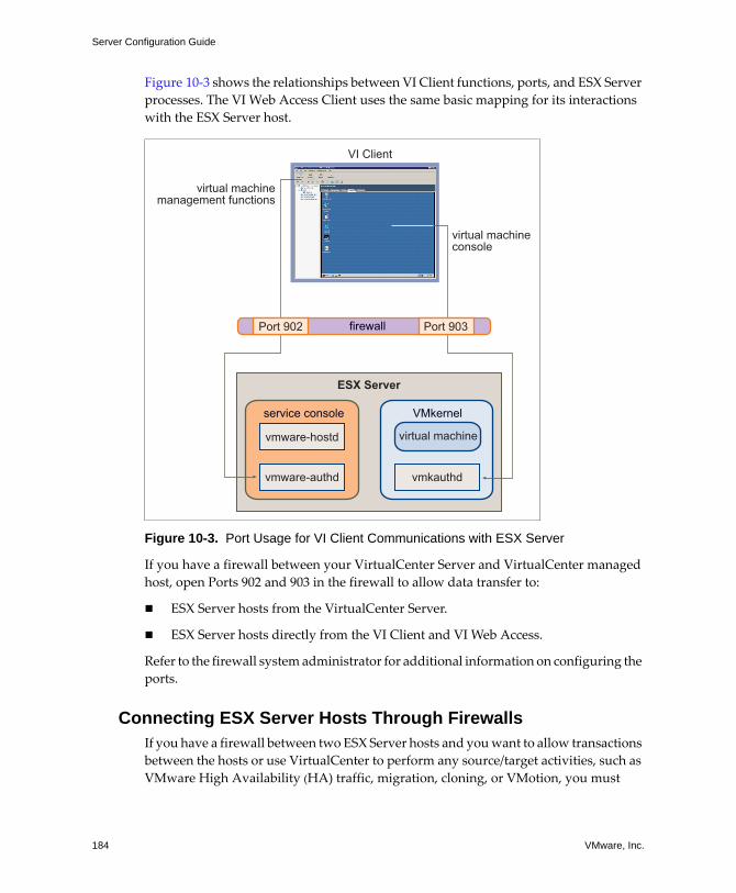
Server Configuration Guide
184 VMware, Inc.
Figure 10‐3 shows the relationships between VI Client functions, ports, and ESX Server processes. The VI Web Access Client uses the same basic mapping for its interactions with the ESX Server host.
Figure 10-3. Port Usage for VI Client Communications with ESX Server
If you have a firewall between your VirtualCenter Server and VirtualCenter managed host, open Ports 902 and 903 in the firewall to allow data transfer to:
! ESX Server hosts from the VirtualCenter Server.
! ESX Server hosts directly from the VI Client and VI Web Access.
Refer to the firewall system administrator for additional information on configuring the ports.
Connecting ESX Server Hosts Through FirewallsIf you have a firewall between two ESX Server hosts and you want to allow transactions between the hosts or use VirtualCenter to perform any source/target activities, such as VMware High Availability (HA) traffic, migration, cloning, or VMotion, you must
ESX Server
VI Client
Port 902
vmware-hostd
vmware-authd vmkauthd
virtual machinemanagement functions
virtual machineconsole
Port 903firewall
VMkernelservice console
virtual machine
VMware, Inc. 185
Chapter 10 Securing an ESX Server Configuration
configure a connection through which the managed hosts can receive data. To do so, you open ports in the following ranges:
! 902 (server‐to‐server migration and provisioning traffic)
! 2050�5000 (for HA traffic)
! 8000 (for VMotion)
! 8042�8045 (for HA traffic)
Refer to the firewall system administrator for additional information on configuring the ports. For more detailed information on the directionality and protocol for these ports, see �TCP and UDP Ports for Management Access� on page 180.
Opening Firewall Ports for Supported Services and Management Agents
Use VI Client to configure the service console firewall to accept commonly supported services and installed management agents. When you configure the ESX Server host security profile in VirtualCenter, you add or remove these services or agents, automatically opening or closing predetermined ports in the firewall to allow communication with the service or agent. The following is a list of the services and agents you can add or remove:
! NIS client
! NFS client (insecure service)
! SMB client (insecure service)
! FTP client (insecure service)
! SSH client
! Telnet client (insecure service)
! NTP client
! iSCSI software client
! SSH server
! Telnet server (insecure service)
! FTP server (insecure service)
! NFS server (insecure service)
! CIM HTTP server (insecure service)
! CIM HTTPS server
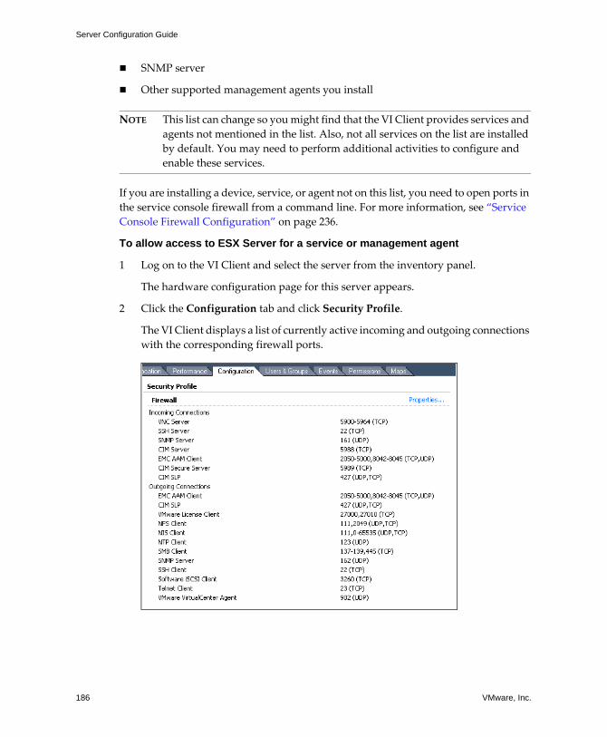
Server Configuration Guide
186 VMware, Inc.
! SNMP server
! Other supported management agents you install
NOTE This list can change so you might find that the VI Client provides services and agents not mentioned in the list. Also, not all services on the list are installed by default. You may need to perform additional activities to configure and enable these services.
If you are installing a device, service, or agent not on this list, you need to open ports in the service console firewall from a command line. For more information, see �Service Console Firewall Configuration� on page 236.
To allow access to ESX Server for a service or management agent
1 Log on to the VI Client and select the server from the inventory panel.
The hardware configuration page for this server appears.
2 Click the Configuration tab and click Security Profile.
The VI Client displays a list of currently active incoming and outgoing connections with the corresponding firewall ports.
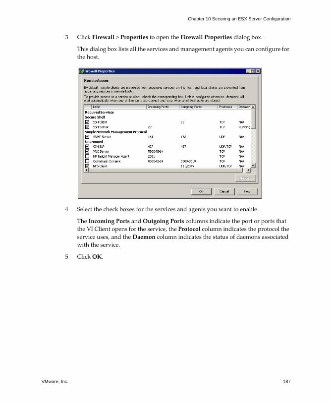
VMware, Inc. 187
Chapter 10 Securing an ESX Server Configuration
3 Click Firewall > Properties to open the Firewall Properties dialog box.
This dialog box lists all the services and management agents you can configure for the host.
4 Select the check boxes for the services and agents you want to enable.
The Incoming Ports and Outgoing Ports columns indicate the port or ports that the VI Client opens for the service, the Protocol column indicates the protocol the service uses, and the Daemon column indicates the status of daemons associated with the service.
5 Click OK.
Server Configuration Guide
188 VMware, Inc.
Securing Virtual Machines with VLANsThe network can be one of the most vulnerable parts of any system. Just as the physical network requires protection, so does your virtual machine network. If your virtual machine network is connected to a physical network, it can be subject to breaches to the same degree that a network made up of physical machines would be. Even if the virtual machine network is isolated from any physical network, virtual machines within the network can be subject to attacks from other virtual machines in the network. The requirements for securing virtual machines are often the same as those for physical machines.
Virtual machines are isolated from each other. One virtual machine can�t read or write another virtual machine�s memory, access its data, use its applications, and so forth. However, within the network, any virtual machine or group of virtual machines can still be the target of unauthorized access from other virtual machines and might require further protection by external means. You can add this level of security by:
! Adding firewall protection to your virtual network by installing and configuring software firewalls on some or all of its virtual machines.
NOTE For efficiency, you can set up private virtual machine Ethernet networks, or virtual networks. With virtual networks, you install a software firewall on a virtual machine at the head of the virtual network. This serves as a protective buffer between the physical network adapter and the remaining virtual machines in the virtual network.
Installing a software firewall on virtual machines at the head of virtual networks is a good security practice. However, because software firewalls can slow performance, balance your security needs against performance before deciding to install software firewalls on virtual machines elsewhere in the virtual network. For more information on virtual networks, see �Networking Concepts� on page 8.
! Keeping different virtual machine zones within a host on different network segments. If you isolate virtual machine zones on their own network segments, you minimize the risks of data leakage from one virtual machine zone to the next. Segmentation prevents various threats, including Address Resolution Protocol (ARP) spoofing in which an attacker manipulates the ARP table to remap MAC and IP addresses, thereby gaining access to network traffic to and from a host. Attackers use ARP spoofing to generate denials of service, hijack the target system, and otherwise disrupt the virtual network.
VMware, Inc. 189
Chapter 10 Securing an ESX Server Configuration
Planning segmentation carefully lowers the chances of packet transmissions between virtual machine zones, thus preventing sniffing attacks, which require sending network traffic to the victim. Also, an attacker cannot leverage an insecure service in one virtual machine zone to access other virtual machine zones in the host. against various security threats. You can implement segmentation using either of two approaches, each of which has different benefits.
! Use separate physical network adapters for virtual machine zones to ensure that the zones are isolated. Maintaining separate physical network adapters for virtual machine zones is probably the most secure method and is less prone to misconfiguration after the initial segment creation.
! Set up Virtual Local Area Networks (VLANs) to help safeguard your network. Because VLANs provide the almost all of the security benefits inherent in implementing physically separate networks without the hardware overhead, they offer a viable solution that can save you the cost of deploying and maintaining additional devices, cabling, and so forth.
VLANs are an IEEE standard networking scheme with specific tagging methods that allow routing of packets to only those ports that are part of the VLAN. When properly configured, VLANs provide a dependable means for you to protect a set of virtual machines from accidental or malicious intrusions.
VLANs let you segment a physical network so that two machines in the network are unable to transmit packets back and forth unless they are part of the same VLAN. For example, accounting records and transactions are among a company�s most sensitive internal information. In a company whose sales, shipping, and accounting employees
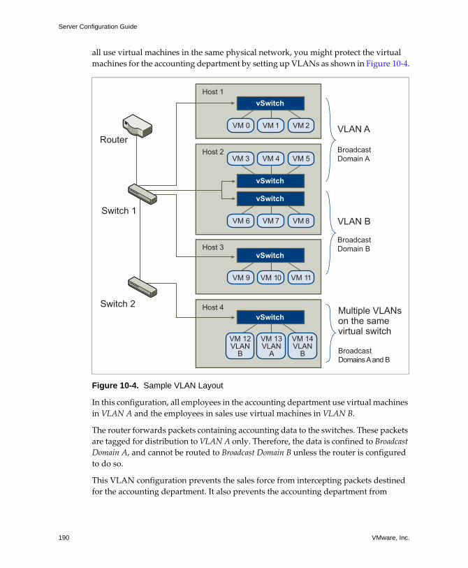
Server Configuration Guide
190 VMware, Inc.
all use virtual machines in the same physical network, you might protect the virtual machines for the accounting department by setting up VLANs as shown in Figure 10‐4.
Figure 10-4. Sample VLAN Layout
In this configuration, all employees in the accounting department use virtual machines in VLAN A and the employees in sales use virtual machines in VLAN B.
The router forwards packets containing accounting data to the switches. These packets are tagged for distribution to VLAN A only. Therefore, the data is confined to Broadcast Domain A, and cannot be routed to Broadcast Domain B unless the router is configured to do so.
This VLAN configuration prevents the sales force from intercepting packets destined for the accounting department. It also prevents the accounting department from
VM 3 VM 4
vSwitch
VM 5
vSwitch
VM 6 VM 7 VM 8
vSwitch
VM 0 VM 1 VM 2
vSwitch
VM 9 VM 10 VM 11
VM 12VLAN
B
VM 13VLAN
A
VM 14VLAN
B
vSwitch
Router
Host 1
Host 3
Host 4
Host 2
Switch 1
Switch 2Multiple VLANson the samevirtual switch
BroadcastDomains A and B
VLAN A
BroadcastDomain A
VLAN B
BroadcastDomain B
VMware, Inc. 191
Chapter 10 Securing an ESX Server Configuration
receiving packets intended for the sales group. Note that the virtual machines serviced by a single virtual switch can be in different VLANs.
The following section provides suggestions for securing your network through virtual switches and VLANs. The section covers the following topics:
! �Security Considerations for VLANs� on page 191
! �Virtual Switch Protection and VLANs� on page 193
! �Securing Virtual Switch Ports� on page 195
Security Considerations for VLANsESX Server features a complete IEEE 802.1q‐compliant VLAN implementation. The way you set up VLANs to secure parts of a network depends on factors such as the guest operating system you install, the way your network equipment is configured, and so forth. While VMware cannot make specific recommendations on how to set up VLANs, here are some factors to consider when using a VLAN deployment as part of your security enforcement policy:
! Treat VLANs as part of a broader security implementation � VLANs are an effective means of controlling where and how widely data is transmitted within the network. If an attacker gains access to the network, the attack is likely to be limited to the VLAN that served as the entry point, lessening the risk to the network as a whole.
VLANs provide protection only in that they control how data is routed and contained after it passes through the switches and enters the network. You can use VLANs to help secure Layer 2 of your network model�the data link layer. However, configuring VLANs doesn�t protect the physical layer of your network model or any of the other layers. Even if you create VLANs, you should provide additional protection by securing your hardware (routers, hubs, and so forth) and encrypting data transmissions.
VLANs are not a substitute for firewalls in your virtual machine configurations. Most network configurations that include VLANs also include software firewalls. If you include VLANs in your virtual network, be sure that any firewalls you install are VLAN‐aware.
! Be sure your VLANs are properly configured � Equipment misconfiguration and network hardware, firmware, or software defects can make a VLAN susceptible to VLAN hopping attacks. VLAN hopping occurs when an attacker with authorized access to one VLAN creates packets that trick physical switches into transmitting the packets to another VLAN that the attacker is not authorized to access. Vulnerability to this type of attack usually results from a switch being
Server Configuration Guide
192 VMware, Inc.
misconfigured for native VLAN operation, in which the switch can receive and transmit untagged packets.
To help prevent VLAN hopping, keep your equipment up to date by installing hardware and firmware updates as they become available. Also, be sure to follow your vendor�s best practice guidelines when configuring your equipment.
Be aware that VMware virtual switches don�t support the concept of a native VLAN. All data passed on these switches is appropriately tagged. However, because there might be other switches in the network that are configured for native VLAN operation, VLANs configured with virtual switches can still be vulnerable to VLAN hopping.
If you plan to use VLANs to enforce network security, VMware recommends that you disable the native VLAN feature for all switches unless you have a compelling need to operate some of your VLANs in native mode. If you need to use native VLAN, pay attention to your switch vendor�s configuration guidelines for this feature.
! Create a separate VLAN or virtual switch for communication between management tools and the service console � Whether you use a management client or the command line, all configuration tasks for ESX Server are performed through the service console, including configuring storage, controlling aspects of virtual machine behavior, and setting up virtual switches or virtual networks. Because the service console is the point of control for ESX Server, safeguarding it from misuse is crucial.
While VMware ESX Server management clients use authentication and encryption to prevent unauthorized access to the service console, other services might not offer the same protection. If attackers gain access to the service console, they are free to reconfigure many attributes of the ESX Server host. For example, they could change the entire virtual switch configuration, change authorization methods, and so forth.
Network connectivity for the service console is established through virtual switches. To provide better protection for this critical ESX Server component, VMware recommends that you isolate the service console using one of these methods:
! Create a separate VLAN for management tool communication with the service console.
! Configure network access for management tool connections with the service console through a single virtual switch and one or more uplink ports.
VMware, Inc. 193
Chapter 10 Securing an ESX Server Configuration
Both methods prevent anyone without access to the service console VLAN or virtual switch from seeing traffic to and from the service console. They also prevent attackers from sending any packets to the service console. As an alternative, you can choose to configure the service console on a separate physical network segment instead. Physical segmentation provides a degree of additional security in that it is less prone to later misconfiguration
In addition to setting up a separate VLANs or virtual switch for management tool communication with the service console, you should set up separate a VLAN or virtual switch for VMotion and for network attached storage.
NOTE If your configuration includes an iSCSI SAN configured directly through the host rather than through a hardware adapter, you should create a separate virtual switch that provides shared network connectivity for a the service console and for iSCSI. This second network connection for the service console is in addition to the primary service console network connection that you use for management tool communications. The second service console network connection supports iSCSI activities only, and you should not use it for any management activities or management tool communications.
Virtual Switch Protection and VLANsVMware virtual switches provide safeguards against certain threats to VLAN security. Because of the way that virtual switches are designed, they protect VLANs against a variety of attacks, many of which involve VLAN hopping. Having this protection does not guarantee that your virtual machine configuration is invulnerable to other types of attacks. For example, virtual switches do not protect the physical network against these attacks, just the virtual network.
The following list gives you an idea of some attacks virtual switches and VLANs can protect against.
! MAC flooding � These attacks flood a switch with packets containing MAC addresses tagged as having come from different sources. Many switches use a Content‐Addressable Memory (CAM) table to learn and store the source address for each packet. When the table is full, the switch may enter a fully open state in which every incoming packet is broadcast on all ports, letting the attacker see all the switch�s traffic. This state might result in packet leakage across VLANs.
While VMware virtual switches store a MAC address table, they don�t get the MAC addresses from observable traffic and are not vulnerable to this type of attack.
Server Configuration Guide
194 VMware, Inc.
! 802.1q and ISL tagging attacks � These attacks force a switch to redirect frames from one VLAN to another by tricking the switch into acting as a trunk and broadcasting the traffic to other VLANs.
VMware virtual switches don�t perform the dynamic trunking required for this type of attack and, therefore, are not vulnerable.
! Double‐encapsulation attacks � These attacks occur when an attacker creates a double‐encapsulated packet in which the VLAN identifier in the inner tag is different from the VLAN identifier in the outer tag. For backward compatibility, native VLANs strip the outer tag from transmitted packets unless configured to do otherwise. When a native VLAN switch strips the outer tag, only the inner tag is left, and that inner tag routes the packet to a different VLAN than the one identified in the now‐missing outer tag.
VMware virtual switches drop any double‐encapsulated frames that a virtual machine attempts to send on a port configured for a specific VLAN. Therefore, they are not vulnerable to this type of attack.
! Multicast brute‐force attacks � These attacks involve sending large numbers of multicast frames to a known VLAN almost simultaneously in hopes of overloading the switch so that it mistakenly allows some of the frames to broadcast to other VLANs.
VMware virtual switches do not allow frames to leave their correct broadcast domain (VLAN) and are not vulnerable to this type of attack.
! Spanning‐tree attacks � These attacks target Spanning‐Tree Protocol (STP), which is used to control bridging between parts of the LAN. The attacker sends Bridge Protocol Data Unit (BPDU) packets that attempt to change the network topology, establishing himself or herself as the root bridge. As the root bridge, the attacker can sniff the contents of transmitted frames.
VMware virtual switches don�t support STP and are not vulnerable to this type of attack.
! Random frame attacks � These attacks involve sending large numbers of packets in which the source and destination addresses stay the same, but in which fields are randomly changed in length, type, or content. The goal of this attack is to force packets to be mistakenly rerouted to a different VLAN.
VMware virtual switches are not vulnerable to this type of attack.
Because new security threats develop over time, do not consider this an exhaustive list of attacks. Regularly check VMware security resources on the Web (http://www.vmware.com/vmtn/technology/security) to learn about security, recent security alerts, and VMware security tactics.
VMware, Inc. 195
Chapter 10 Securing an ESX Server Configuration
Securing Virtual Switch PortsAs with physical network adapters, a virtual network adapter can send frames that appear to be from a different machine or impersonate another machine so that it is able to receive network frames intended for that machine. Also, like physical network adapters, a virtual network adapter can be configured such that it receives frames targeted for other machines.
When you create a virtual switch for your network, you add port groups to impose a policy configuration for the virtual machines, storage systems, and so forth attached to the switch. You create virtual switches through the VI Client.
As part of adding a port or port group to a virtual switch, the VI Client configures a security profile for the port. You can use this security profile to ensure that ESX Server prevents the guest operating systems for its virtual machines from impersonating other machines on the network. This security feature is implemented so that the guest operating system responsible for the impersonation does not detect that the impersonation has been prevented.
The security profile determines how strongly you enforce protection against impersonation and interception attacks on virtual machines. To correctly use the settings in the security profile, you need to understand the basics of how virtual network adapters control transmissions and how attacks are staged at this level.
Each virtual network adapter has its own MAC address assigned when the adapter is created. This address is called the initial MAC address. Although the initial MAC address can be reconfigured from outside the guest operating system, it cannot be changed by the guest operating system. In addition, each adapter has an effective MAC address that filters out incoming network traffic with a destination MAC address different from the effective MAC address. The guest operating system is responsible for setting the effective MAC address and typically matches the effective MAC address to the initial MAC address.
When sending packets, an operating system typically places its own network adapterʹs effective MAC address in the source MAC address field of the Ethernet frame. It also places the MAC address for the receiving network adapter in the destination MAC address field. The receiving adapter accepts packets only when the destination MAC address in the packet matches its own effective MAC address.
Upon creation, a network adapter�s effective MAC address and initial MAC address are the same. The virtual machine�s operating system can alter the effective MAC address to another value at any time. If an operating system changes the effective MAC address, its network adapter then receives network traffic destined for the new MAC address. The operating system can send frames with an impersonated source MAC address at
Server Configuration Guide
196 VMware, Inc.
any time. Thus, an operating system can stage malicious attacks on the devices in a network by impersonating a network adapter authorized by the receiving network.
You can use virtual switch security profiles on ESX Server hosts protect against this type of attack by setting three options:
! MAC address changes � By default, this option is set to Accept, meaning that the ESX Server host accepts requests to change the effective MAC address to other than the initial MAC address. The MAC Address Changes option setting affects traffic received by a virtual machine.
To protect against MAC impersonation, you can set this option to Reject. If you do, the ESX Server host does not honor requests to change the effective MAC address to anything other than the initial MAC address. Instead, the port that the virtual adapter used to send the request is disabled. As a result, the virtual adapter does not receive any more frames until it changes the effective MAC address to match the initial MAC address. The guest operating system does not detect that the MAC address change has not been honored.
NOTE In some situations, you might have a legitimate need for more than one adapter to have the same MAC address on a network�for example, if you are using Microsoft Network Load Balancing in unicast mode. Note that when Microsoft Network Load Balancing is used in the standard multicast mode, adapters do not share MAC addresses.
! Forged transmissions � By default, this option is set to Accept, meaning the ESX Server host does not compare source and effective MAC addresses. The Forged Trasmits option setting affects traffic transmitted from a virtual machine.
To protect against MAC impersonation, you can set this option to Reject. If you do, the ESX Server host compares the source MAC address being transmitted by the operating system with the effective MAC address for its adapter to see if they match. If the addresses don�t match, ESX Server drops the packet.
The guest operating system does not detect that its virtual network adapter cannot send packets using the impersonated MAC address. The ESX Server host intercepts any packets with impersonated addresses before they are delivered, and the guest operating system might assume that the packets have been dropped.
! Promiscuous mode operation � By default, this option is set to Reject, meaning that the virtual network adapter cannot operate in promiscuous mode. Promiscuous mode eliminates any reception filtering that the virtual network adapter would perform so that very frame that the guest operating system receives all traffic observed on the wire.
VMware, Inc. 197
Chapter 10 Securing an ESX Server Configuration
While promiscuous mode can be useful for tracking network activity, it is an insecure mode of operation because any adapter in promiscuous mode had access to the packets regardless of whether some of the packets should be received only by a particular network adapter. This means that an administrator or root user within a virtual machine can potentially view traffic destined for other guest or host operating systems.
NOTE In some situations, you might have a legitimate need to configure a virtual switch to operate in promiscuous mode�for example, if you are running network intrusion detection software or a packet sniffer.
If you need to change any of these default settings for a port, you must modify the security profile by editing virtual switch settings in the VI Client. For information on editing these settings, see �Virtual Switch Policies� on page 39.
Securing iSCSI StorageThe storage you configure for an ESX Server host might include one or more storage area networks (SANs) that use iSCSI. iSCSI is a means of accessing SCSI devices and exchanging data records using TCP/IP protocol over a network port rather than through a direct connection to a SCSI device. In iSCSI transactions, blocks of raw SCSI data are encapsulated in iSCSI records and transmitted to the requesting device or user.
iSCSI SANs let you make efficient use of existing Ethernet infrastructures to provide ESX Server hosts access to storage resources that they can dynamically share. As such, iSCSI SANs provide an economical storage solution for environments that rely on a common storage pool to serve numerous users. As with any networked system, your iSCSI SANs can be subject to security breaches. When you configure iSCSI on an ESX Server host, you can take several measures to minimize security risks.
NOTE The requirements and procedures for securing an iSCSI SAN are similar for the hardware iSCSI adapters you can use with ESX Server hosts and for iSCSI configured directly through the ESX Server host. For information on configuring iSCSI adapters and storage, see �iSCSI Storage� on page 96.
The following section tells you how to configure authentication for iSCSI SANs and provides suggestions for securing iSCSI SANs. The section covers the following topics:
! �Securing iSCSI Devices Through Authentication� on page 198
! �Protecting an iSCSI SAN� on page 202
Server Configuration Guide
198 VMware, Inc.
Securing iSCSI Devices Through AuthenticationOne means of securing iSCSI devices from unwanted intrusion is to require that the ESX Server host, or initiator, be authenticated by the iSCSI device, or target, whenever the host attempts to access data on the target LUN. The goal of authentication is to prove that the initiator has the right to access a target, a right granted when you configure authentication.
You have two choices when setting up authentication for iSCSI SANs on the ESX Server host:
! Challenge Handshake Authentication Protocol (CHAP) � You can configure the iSCSI SAN to use CHAP authentication. In CHAP authentication, when the initiator contacts an iSCSI target, the target sends a predefined ID value and a random value, or key, to the initiator. The initiator then creates a one‐way hash value that it sends to the target. The hash contains three elements: a predefined ID value, the random value sent by the target, and a private value, or CHAP secret, shared by the initiator and target. When the target receives the hash from the initiator, it creates its own hash value using the same elements and compares it to the initiator�s hash. If the results match, the target authenticates the initiator.
ESX Server supports one‐way CHAP authentication for iSCSI. It does not support bi‐directional CHAP. In one‐way CHAP authentication, the target authenticates the initiator, but the initiator does not authenticate the target. The initiator has only one set of credentials, and these credentials are used by all the iSCSI targets.
ESX Server supports CHAP authentication at the HBA level only. It does not support per‐target CHAP authentication, which enables you to configure different credentials for each target to achieve greater target refinement.
! Disabled � You can configure the iSCSI SAN to use no authentication. Be aware that communications between the initiator and target are still authenticated in a rudimentary way because the iSCSI target devices are typically set up to communicate with specific initiators only.
Choosing not to enforce more stringent authentication can make sense if your iSCSI storage is housed in one location and you create a dedicated network or VLAN to service all your iSCSI devices. The premise here is that the iSCSI configuration is secure because it is isolated from any unwanted access, much as a Fibre Channel SAN would be.
As a basic rule, disable authentication only if you are willing to risk an attack to the iSCSI SAN or cope with problems that result from human error.
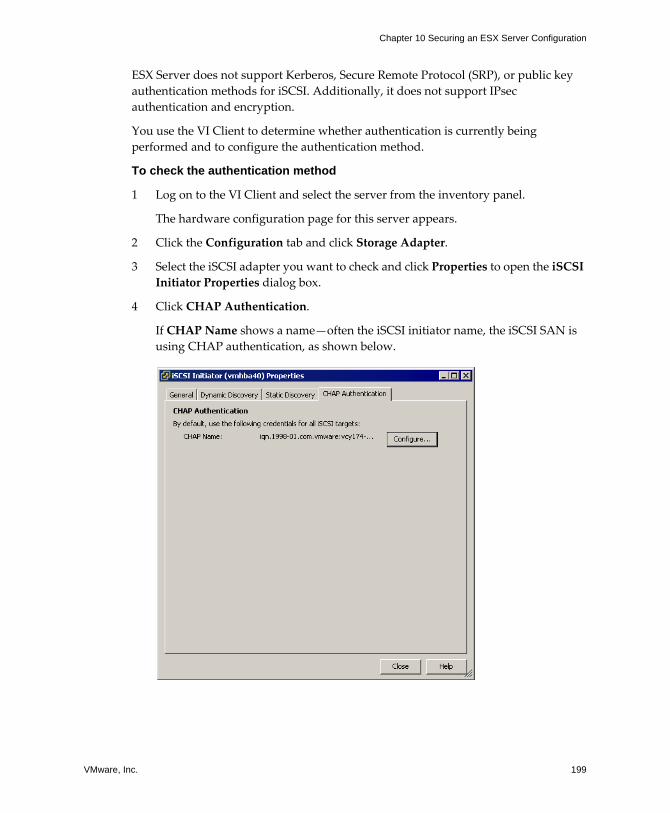
VMware, Inc. 199
Chapter 10 Securing an ESX Server Configuration
ESX Server does not support Kerberos, Secure Remote Protocol (SRP), or public key authentication methods for iSCSI. Additionally, it does not support IPsec authentication and encryption.
You use the VI Client to determine whether authentication is currently being performed and to configure the authentication method.
To check the authentication method
1 Log on to the VI Client and select the server from the inventory panel.
The hardware configuration page for this server appears.
2 Click the Configuration tab and click Storage Adapter.
3 Select the iSCSI adapter you want to check and click Properties to open the iSCSI Initiator Properties dialog box.
4 Click CHAP Authentication.
If CHAP Name shows a name�often the iSCSI initiator name, the iSCSI SAN is using CHAP authentication, as shown below.
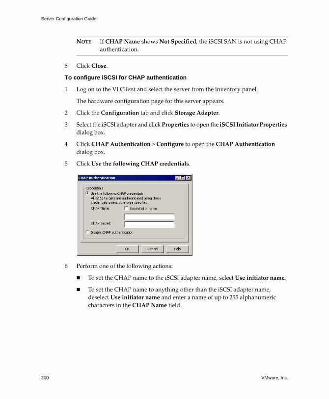
Server Configuration Guide
200 VMware, Inc.
NOTE If CHAP Name shows Not Specified, the iSCSI SAN is not using CHAP authentication.
5 Click Close.
To configure iSCSI for CHAP authentication
1 Log on to the VI Client and select the server from the inventory panel.
The hardware configuration page for this server appears.
2 Click the Configuration tab and click Storage Adapter.
3 Select the iSCSI adapter and click Properties to open the iSCSI Initiator Properties dialog box.
4 Click CHAP Authentication > Configure to open the CHAP Authentication dialog box.
5 Click Use the following CHAP credentials.
6 Perform one of the following actions:
! To set the CHAP name to the iSCSI adapter name, select Use initiator name.
! To set the CHAP name to anything other than the iSCSI adapter name, deselect Use initiator name and enter a name of up to 255 alphanumeric characters in the CHAP Name field.
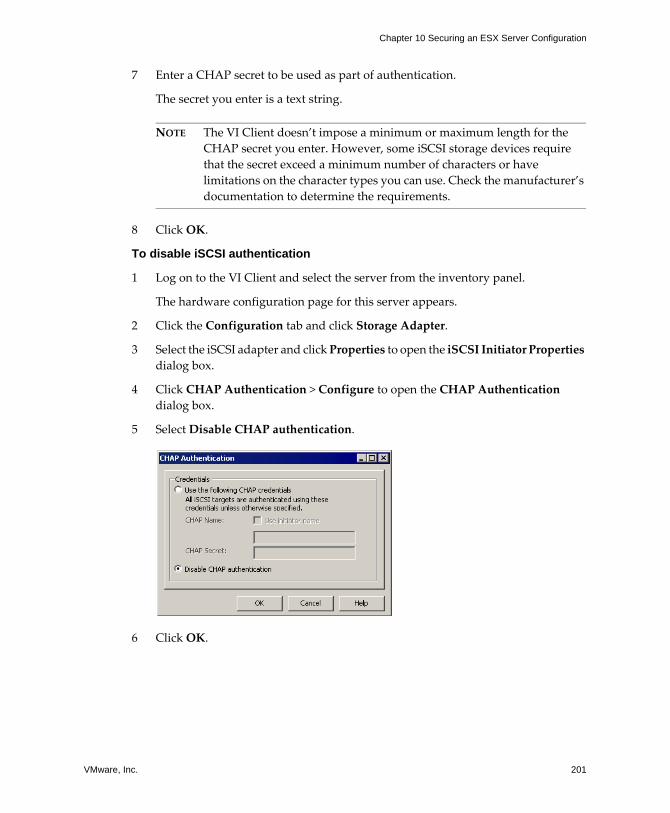
VMware, Inc. 201
Chapter 10 Securing an ESX Server Configuration
7 Enter a CHAP secret to be used as part of authentication.
The secret you enter is a text string.
NOTE The VI Client doesn�t impose a minimum or maximum length for the CHAP secret you enter. However, some iSCSI storage devices require that the secret exceed a minimum number of characters or have limitations on the character types you can use. Check the manufacturer�s documentation to determine the requirements.
8 Click OK.
To disable iSCSI authentication
1 Log on to the VI Client and select the server from the inventory panel.
The hardware configuration page for this server appears.
2 Click the Configuration tab and click Storage Adapter.
3 Select the iSCSI adapter and click Properties to open the iSCSI Initiator Properties dialog box.
4 Click CHAP Authentication > Configure to open the CHAP Authentication dialog box.
5 Select Disable CHAP authentication.
6 Click OK.
Server Configuration Guide
202 VMware, Inc.
Protecting an iSCSI SANWhen planning your iSCSI configuration, you should take measures to improve the overall security of the iSCSI SAN. Your iSCSI configuration is only as secure as your IP network, so by enforcing good security standards when setting up your network, you help safeguard your iSCSI storage.
Here are some specific suggestions:
! Protecting transmitted data � A primary security risk in iSCSI SANs is that an attacker might sniff transmitted storage data.
VMware recommends that you take additional measures to prevent attackers from easily seeing iSCSI data. Neither the hardware iSCSI adapter nor the ESX Server host iSCSI initiator encrypts the data they transmit to and from the targets, making the data more vulnerable to sniffing attacks.
Allowing your virtual machines to share virtual switches and VLANs with your iSCSI configuration potentially exposes iSCSI traffic to misuse by a virtual machine attacker. To help ensure that intruders can�t listen to iSCSI transmissions, make sure that none of your virtual machines can see the iSCSI storage network.
If you use a hardware iSCSI adapter, you can accomplish this by making sure that the iSCSI adapter and ESX physical network adapter are not inadvertently connected outside the host by virtue of sharing a switch or some other means. If you configure iSCSI directly through the ESX Server host, you can accomplish this
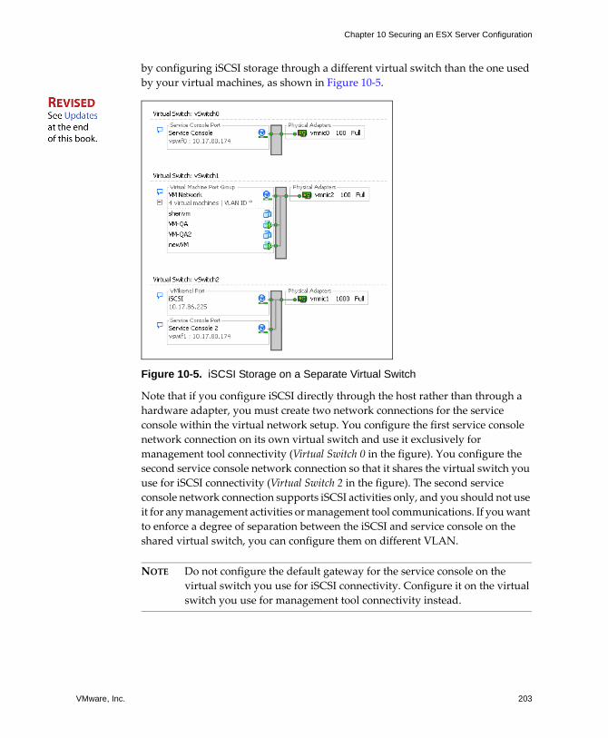
VMware, Inc. 203
Chapter 10 Securing an ESX Server Configuration
by configuring iSCSI storage through a different virtual switch than the one used by your virtual machines, as shown in Figure 10‐5.
Figure 10-5. iSCSI Storage on a Separate Virtual Switch
Note that if you configure iSCSI directly through the host rather than through a hardware adapter, you must create two network connections for the service console within the virtual network setup. You configure the first service console network connection on its own virtual switch and use it exclusively for management tool connectivity (Virtual Switch 0 in the figure). You configure the second service console network connection so that it shares the virtual switch you use for iSCSI connectivity (Virtual Switch 2 in the figure). The second service console network connection supports iSCSI activities only, and you should not use it for any management activities or management tool communications. If you want to enforce a degree of separation between the iSCSI and service console on the shared virtual switch, you can configure them on different VLAN.
NOTE Do not configure the default gateway for the service console on the virtual switch you use for iSCSI connectivity. Configure it on the virtual switch you use for management tool connectivity instead.
Server Configuration Guide
204 VMware, Inc.
In addition to protecting the iSCSI SAN by giving it a dedicated virtual switch, consider configuring your iSCSI SAN on its own VLAN. Placing your iSCSI configuration on a separate VLAN ensures that no devices other than the iSCSI adapter have visibility into transmissions within the iSCSI SAN.
! Securing iSCSI ports � When you run iSCSI devices, the ESX Server host doesn�t open any ports that listen for network connections. This measure reduces the chances that an intruder can break into the ESX Server host through spare ports and gain control over the host. Therefore, running iSCSI doesn�t present any additional security risks at the ESX Server host end of the connection.
Be aware that any iSCSI target device that you run must have one or more open TCP ports used to listen for iSCSI connections. If any security vulnerabilities exist in the iSCSI device software, your data can be at risk through no fault of ESX Server. To lower this risk, install all security patches provided by your storage equipment manufacturer and limit the devices connected to the iSCSI network.
VMware, Inc. 205
CHAPTER 11 Authentication and User Management
This chapter explains how ESX Server handles user authentication and shows you how to set up user and group permissions. In addition, it discusses encryption for connections to the VI Client, SDK, and VI Web Access as well as configuring a delegate user name for transactions with NFS storage.
This chapter covers the following topics:
! �Securing ESX Server Through Authentication and Permissions� on page 206
! �Encryption and Security Certificates for ESX Server� on page 222
! �Virtual Machine Delegates for NFS Storage� on page 229
Server Configuration Guide
206 VMware, Inc.
Securing ESX Server Through Authentication and Permissions
ESX Server uses the Pluggable Authentication Modules (PAM) structure for authentication when users access the ESX Server host using VirtualCenter, VI Web Access, or the service console. The PAM configuration for VMware services is located in /etc/pam.d/vmware-authd, which stores paths to authentication modules.
The default installation of ESX Server uses /etc/passwd authentication, just as Linux does, but you can configure ESX Server to use another distributed authentication mechanism. If you plan to use a third‐party authentication tool instead of the ESX Server default implementation, refer to the vendor documentation for instructions. As part of setting up third‐party authentication, you might need to update the /etc/pam.d/vmware-authd file with new module information.
Every time a VI Client or VirtualCenter user connects to an ESX Server host, the sinnet process starts an instance of the VMware Authentication Daemon (vmware-authd), which is used as a proxy to pass the information to and from the VMware Host Agent (vmware-host) process. The vmware-authd process receives an incoming connection attempt and hands it off to the vmware-host process, which receives the user name and password from the client and forwards them to the PAM module to perform the authentication.
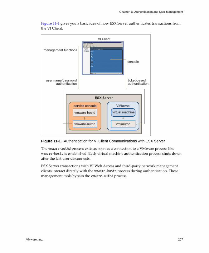
VMware, Inc. 207
Chapter 11 Authentication and User Management
Figure 11‐1 gives you a basic idea of how ESX Server authenticates transactions from the VI Client.
Figure 11-1. Authentication for VI Client Communications with ESX Server
The vmware-authd process exits as soon as a connection to a VMware process like vmware-hostd is established. Each virtual machine authentication process shuts down after the last user disconnects.
ESX Server transactions with VI Web Access and third‐party network management clients interact directly with the vmware-hostd process during authentication. These management tools bypass the vmware-authd process.
ESX Server
VI Client
vmware-hostd
vmware-authd vmkauthd
management functions
console
VMkernelservice console
virtual machine
user name/passwordauthentication
ticket-basedauthentication
Server Configuration Guide
208 VMware, Inc.
To make sure that authentication works efficiently for your site, you might need to perform basic tasks such as setting up users, groups, permissions, and roles, configuring user attributes, adding your own certificates, determining whether you want to use SSL, and so forth. You can learn more about these issues and tasks in this section, which covers the following topics:
! �About Users, Groups, Permissions, and Roles� on page 208
! �Working with Users and Groups on ESX Server Hosts� on page 214
! �Encryption and Security Certificates for ESX Server� on page 222
! �Virtual Machine Delegates for NFS Storage� on page 229
About Users, Groups, Permissions, and RolesAccess to an ESX Server host and its resources is granted when a known user with appropriate permissions logs on to the host with a password that matches the one stored for that user. VirtualCenter uses a similar approach when determining whether to grant access to a user. VirtualCenter and ESX Server hosts determine the level of access for the user based on the permissions assigned to the user. For example, one user might have permissions that allow him or her to create virtual machines on the host and another user might have permissions that allow him or her to power on virtual machines but not create them.
The combination of user name, password, and permissions is the mechanism by which VirtualCenter and ESX Server hosts authenticate a user for access and authorize the user to perform activities. To support this mechanism, the VirtualCenter and ESX Server host maintain lists of authorized users, their passwords, and the permissions assigned to each user. VirtualCenter and ESX Server hosts deny access under the following circumstances:
! A user not in the user list attempts to log on.
! A user enters the wrong password.
! A user is in the list but has not been assigned permissions.
! A user who successfully logged on attempts operations that he or she does not have permission to perform.
VMware, Inc. 209
Chapter 11 Authentication and User Management
As part of managing ESX Server hosts and VirtualCenter, you need to develop user and permission models, which are basic plans for how you want to handle particular types of users and how you want to design your permissions. In developing your user and permission models, be aware that:
! ESX Server and VirtualCenter use sets of privileges, or roles, to control which operations individual users or groups can perform. ESX Server and VirtualCenter provide you with a set of pre‐established roles, but you can also create new ones.
! You can manage users more easily by assigning them to groups. If you create groups, you can apply a role to the group, and this role is inherited by all the users in the group.
Understanding UsersA user is an individual authorized to log on to either an ESX Server host or to VirtualCenter. ESX Server users fall into two categories: those who can access the ESX Server host through VirtualCenter and those who can access the ESX Server host by directly logging on to the host from the VI Client, VI Web Access, a third‐party client, or a command shell. These two categories draw users from different sources.
! VirtualCenter users � Authorized users for VirtualCenter are those included in the Windows domain list referenced by VirtualCenter or are local Windows users on the VirtualCenter host.
You cannot use VirtualCenter to manually create, remove, or otherwise change users. To manipulate the user list or change user passwords, you must do so through the tools you use to manage your Windows domain.
Any changes you make to the Windows domain are reflected in VirtualCenter. However, because you cannot directly manage users in VirtualCenter, the user interface doesn�t provide a user list for you to review. The only time you work with user and group lists is when you select users and groups during role assignment. You will notice these changes only when you select users in order to configure permissions.
! Direct access users � Users authorized to work directly on an ESX Server host are those added to the internal user list by default when ESX Server is installed or by a system administrator after installation.
If you log on to the host as an administrator, you can perform a variety of management activities for these users, such as changing passwords, group memberships, permissions, and so forth. You can also add and remove users.
Server Configuration Guide
210 VMware, Inc.
The user list maintained by VirtualCenter is completely separate from the user list maintained by the ESX Server host. Even if the lists maintained by a host and VirtualCenter appear to have common users (for instance, a user called devuser), these users should be treated as separate users who happen to have the same name. The attributes of devuser in VirtualCenter, including permissions, passwords, and so forth are separate from the attributes of devuser on the ESX Server host. If you log on to VirtualCenter as devuser, you might have permission to view and delete files from a datastore, whereas if you log on to an ESX Server host as devuser, you might not.
Because of the confusion that duplicate naming can cause, VMware recommends that you check the VirtualCenter user list before you create ESX Server host users so that you can avoid creating host users that have the same name as VirtualCenter users. To check for VirtualCenter users, review the Windows domain list.
Understanding GroupsYou can more efficiently manage some user attributes by creating groups. A group is a set of users that you want to manage through a common set of rules and permissions. When you assign permissions to a group, they are inherited by all users in the group, and you do not have to work with the user profiles one by one. Therefore, using groups can significantly reduce the time it takes to set up your permissions model and improve future scalability.
As an administrator, you need to decide how to structure groups to achieve your security and usage goals. For example, three part‐time sales team members work different days, and you want them to share a single virtual machine but not use the virtual machines belonging to sales managers. In this case, you might create a group called SalesShare that includes the three sales people: Mary, John, and Tom. You might then give the SalesShare group permission to interact with only one object, Virtual Machine A. Mary, John, and Tom inherit these permissions and are able to power up Virtual Machine A, start console sessions on Virtual Machine A, and so forth. They cannot perform these actions on the sales managers� virtual machines: Virtual Machines B, C, and D.
The group lists in VirtualCenter and an ESX Server host are drawn from the same sources as their respective user lists. If you are working through VirtualCenter, the group list is called from the Windows domain. If you are logged on to an ESX Server host directly, the group list is called from a table maintained by the host. All the recommendations for how you treat group lists are the same as those for user lists.
VMware, Inc. 211
Chapter 11 Authentication and User Management
Understanding PermissionsFor ESX Server and VirtualCenter, permissions are defined as access roles that consist of a user and the user�s assigned role for an object such as a virtual machine or ESX Server host. Permissions grant users the right to perform specific activities and manage specific objects on an ESX Server host or, if users are working from VirtualCenter, all VirtualCenter‐managed objects. For example, to configure memory for an ESX Server host, you must have a permission that grants host configuration privileges.
Most VirtualCenter and ESX Server users have limited ability to manipulate the objects associated with the host. However, ESX Server provides full access rights and permissions on all virtual objects, such as datastores, hosts, virtual machines, and resource pools, to two users�root and, if the host is under VirtualCenter management, vpxuser. Root and vpxuser have the following permissions:
! root � The root user can perform a complete range of control activities on the specific ESX Server host that he or she is logged on to, including manipulating permissions, creating groups and users, working with events, and so forth. A root user logged on to one ESX Server host cannot control the activities of any other host in the broader ESX Server deployment.
For security reasons, you might not want to use the root user in the Administrator role. In this case, you can change permissions after installation so that the root user no longer has administrative privileges or you can delete the root user�s access permissions altogether through the VI Client as described in the �Managing Users, Groups, Permissions, and Roles� chapter of Basic System Administration. If you do so, you must first create another permission at the root level that has a different user assigned to the Administrator role.
Assigning the Administrator role to a different user helps you maintain security through traceability. The VI Client logs all actions initiated by the Administrator role user as events, providing you with an audit trail. You can use this feature to improve accountability among the various users who act as administrators for the host. If all the administrators log on to the host as the root user, you cannot tell which administrator performed an action. If, instead, you create multiple permissions at the root level�each associated with a different user or user group�you can track the actions of each administrator or administrative group.
After you create an alternative Administrator user, you can safely delete the root user�s permissions or change its role to limit its privileges. If you delete or change the root user�s permissions, you must use the new user you created as the host
Server Configuration Guide
212 VMware, Inc.
authentication point when you bring the host under VirtualCenter management. For more information on roles, see �Understanding Roles� on page 213.
NOTE Configuration commands that you run through the command line interface (esxcfg commands) do not perform an access check.
! vpxuser � This user is VirtualCenter acting as an entity with Administrator rights on the ESX Server host, allowing it to manage activities for that host. vpxuser is created at the time that an ESX Server host is attached to VirtualCenter. It is not present on the ESX Server host unless the host is being managed through VirtualCenter.
When an ESX Server host is managed through VirtualCenter, VirtualCenter has privileges on the host. For example, VirtualCenter can move virtual machines to and from hosts and perform configuration changes needed to support virtual machines.
The VirtualCenter administrator, through vpxuser, can perform most of the same tasks on the host as the root user and also schedule tasks, work with templates, and so forth. However, there are certain activities you cannot perform as a VirtualCenter administrator. These activities, which include directly creating, deleting, or editing users and groups for ESX Server hosts, can be performed only by a user with Administer permissions directly on each ESX Server host.
CAUTION Do not change vpxuser in any way and do not change its permissions. If you do so, you might experience problems in working with the ESX Server host through VirtualCenter.
If you are acting in the Administrator role on and ESX Server host, you can grant permissions on the host to individual users or groups that have been added to the ESX Server user list and group list by default when ESX Server was installed or because they were manually added to the host after installation. If you are acting in the Administrator role in VirtualCenter, you can you can grant permissions to any user or group included in the Windows domain list referenced by VirtualCenter.
NOTE VirtualCenter registers any selected Windows domain user or group through the process of assigning permissions. By default, all users who are members of the local Windows Administrators group on the VirtualCenter Server are granted the same access rights as any user assigned to the Administrator role. Users who are members of the Administrators group can log on as individuals and have full access.
VMware, Inc. 213
Chapter 11 Authentication and User Management
The method you use to configure permissions directly on an ESX Server host is identical to the method you use to configure permissions in VirtualCenter. Also, the list of privileges is the same for both ESX Server and VirtualCenter. For information on configuring permissions and to read about the privileges you can assign, see the Introduction to Virtual Infrastructure.
Understanding RolesVirtualCenter and ESX Server grant access to objects only to users who have been assigned permissions for the object. When you assign a user or group permissions for the object, you do so by pairing the user or group with a role. A role is a pre‐defined set of privileges.
ESX Server hosts provide three default roles, and you cannot change the privileges associated with these roles. Each subsequent default role includes the privileges of the previous role. For example, the Administrator role inherits the privileges of the Read Only role. Roles you create yourself do not inherit privileges from any of the default roles. The default roles are:
! No Access � Users assigned this role for an object cannot view or change the object in any way. For example, a user who has a No Access role for a particular virtual machine cannot see the virtual machine in the VI Client inventory when he or she logs on to the ESX Server host. With a No Access role for a particular object, a user can select the VI Client tabs associated with the no‐access object, but the tab displays no content. For example, if the user doesn�t have access to any virtual machines, he or she can select the Virtual Machines tab but won�t see a virtual machine listing on the tab or any status information�the table is blank.
The No Access role is the default assigned to any user or group you create on an ESX Server host. You can elevate or lower a newly created user�s or group�s role on an object‐by‐object basis.
NOTE The root user and vpxuser are the only users not assigned the No Access role by default. Instead, they are assigned the Administrator role. Do not change the role for these users.
You can delete the root user�s permissions altogether or change its role to No Access as long as you first create a replacement permission at the root level with the Administrator role and associate this role with a different user. If you delete or change the root user�s permissions, you must use the new user you created as the host authentication point when you bring the host under VirtualCenter management.
Server Configuration Guide
214 VMware, Inc.
! Read Only � Users assigned this role for an object are allowed to view the state of the object and details about the object.
With this role, a user can view virtual machine, host, and resource pool attributes. The user cannot view the remote console for a host. All actions through the menus and toolbars are disallowed.
! Administrator � Users assigned this role for an object are allowed to view and perform all actions on the object. This role also includes all permissions inherent in the Read Only role.
You can create custom roles by using the role‐editing facilities in the VI Client to create privilege sets that match your user needs. If you use the VI Client connected to VirtualCenter to manage your ESX Server hosts, you have additional roles to choose from in VirtualCenter. Also, the roles you create directly on an ESX Server host are not accessible within VirtualCenter. You can work with these roles only if you log on to the host directly from the VI Client.
If you manage ESX Server hosts through VirtualCenter, be aware that maintaining custom roles in both the host and VirtualCenter can result in confusion and misuse. In this type of configuration, VMware recommends that you maintain custom roles only in VirtualCenter. For information on creating, altering, and deleting roles as well as a discussion of additional roles available in VirtualCenter, see Basic System Administration.
Working with Users and Groups on ESX Server HostsIf you are directly connected to an ESX Server host through the VI Client, you can create, edit, and delete users and groups. These users and groups are visible in the VI Client whenever you log on to the ESX Server host but are not available if you log on to VirtualCenter.
The following section explains how to work with users and groups in the VI Client directly connected to an ESX Server host. The section covers basic tasks you can perform for users and groups, such as viewing and sorting information and exporting reports. It also shows you how to create, delete, and edit users and groups.
NOTE You can also create roles and set permissions through a direct connection to the ESX Server host. Because these tasks are more widely performed in VirtualCenter, see the Introduction to Virtual Infrastructure for information on working with permissions and roles.
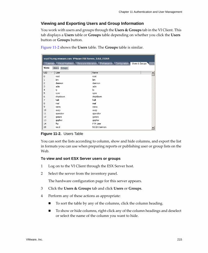
VMware, Inc. 215
Chapter 11 Authentication and User Management
Viewing and Exporting Users and Group InformationYou work with users and groups through the Users & Groups tab in the VI Client. This tab displays a Users table or Groups table depending on whether you click the Users button or Groups button.
Figure 11‐2 shows the Users table. The Groups table is similar.
Figure 11-2. Users Table
You can sort the lists according to column, show and hide columns, and export the list in formats you can use when preparing reports or publishing user or group lists on the Web.
To view and sort ESX Server users or groups
1 Log on to the VI Client through the ESX Server host.
2 Select the server from the inventory panel.
The hardware configuration page for this server appears.
3 Click the Users & Groups tab and click Users or Groups.
4 Perform any of these actions as appropriate:
! To sort the table by any of the columns, click the column heading.
! To show or hide columns, right‐click any of the column headings and deselect or select the name of the column you want to hide.
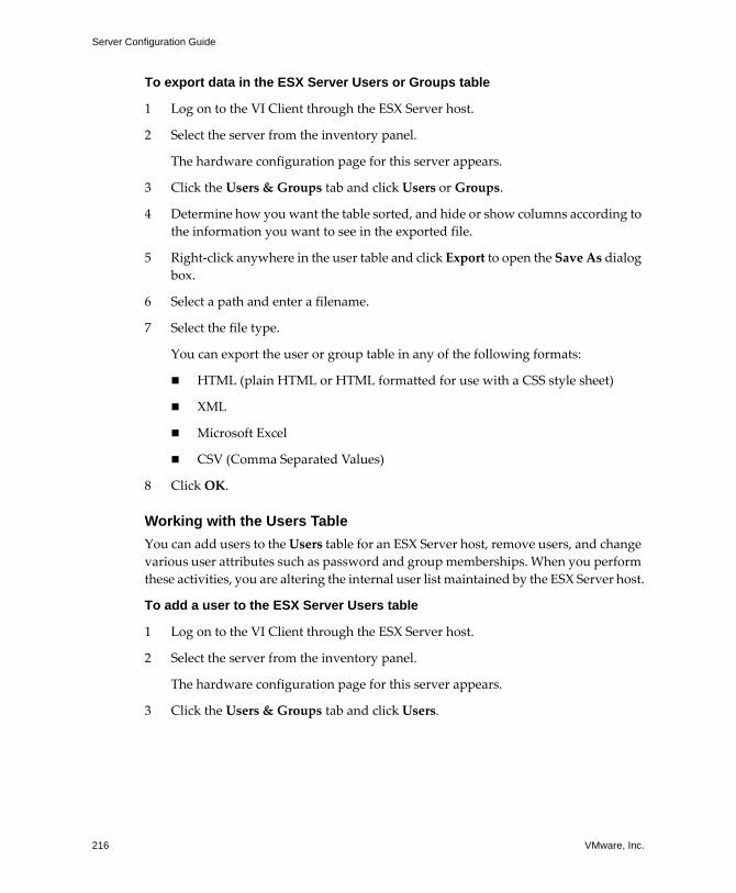
Server Configuration Guide
216 VMware, Inc.
To export data in the ESX Server Users or Groups table
1 Log on to the VI Client through the ESX Server host.
2 Select the server from the inventory panel.
The hardware configuration page for this server appears.
3 Click the Users & Groups tab and click Users or Groups.
4 Determine how you want the table sorted, and hide or show columns according to the information you want to see in the exported file.
5 Right‐click anywhere in the user table and click Export to open the Save As dialog box.
6 Select a path and enter a filename.
7 Select the file type.
You can export the user or group table in any of the following formats:
! HTML (plain HTML or HTML formatted for use with a CSS style sheet)
! XML
! Microsoft Excel
! CSV (Comma Separated Values)
8 Click OK.
Working with the Users TableYou can add users to the Users table for an ESX Server host, remove users, and change various user attributes such as password and group memberships. When you perform these activities, you are altering the internal user list maintained by the ESX Server host.
To add a user to the ESX Server Users table
1 Log on to the VI Client through the ESX Server host.
2 Select the server from the inventory panel.
The hardware configuration page for this server appears.
3 Click the Users & Groups tab and click Users.
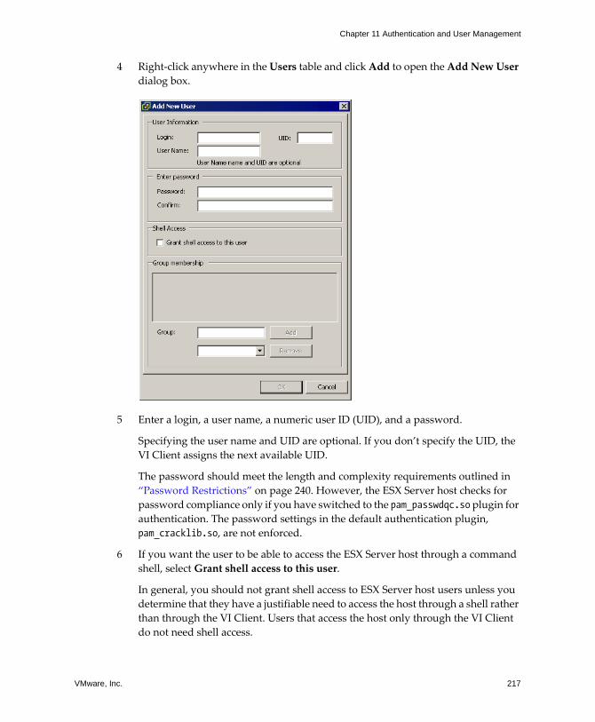
VMware, Inc. 217
Chapter 11 Authentication and User Management
4 Right‐click anywhere in the Users table and click Add to open the Add New User dialog box.
5 Enter a login, a user name, a numeric user ID (UID), and a password.
Specifying the user name and UID are optional. If you don�t specify the UID, the VI Client assigns the next available UID.
The password should meet the length and complexity requirements outlined in �Password Restrictions� on page 240. However, the ESX Server host checks for password compliance only if you have switched to the pam_passwdqc.so plugin for authentication. The password settings in the default authentication plugin, pam_cracklib.so, are not enforced.
6 If you want the user to be able to access the ESX Server host through a command shell, select Grant shell access to this user.
In general, you should not grant shell access to ESX Server host users unless you determine that they have a justifiable need to access the host through a shell rather than through the VI Client. Users that access the host only through the VI Client do not need shell access.
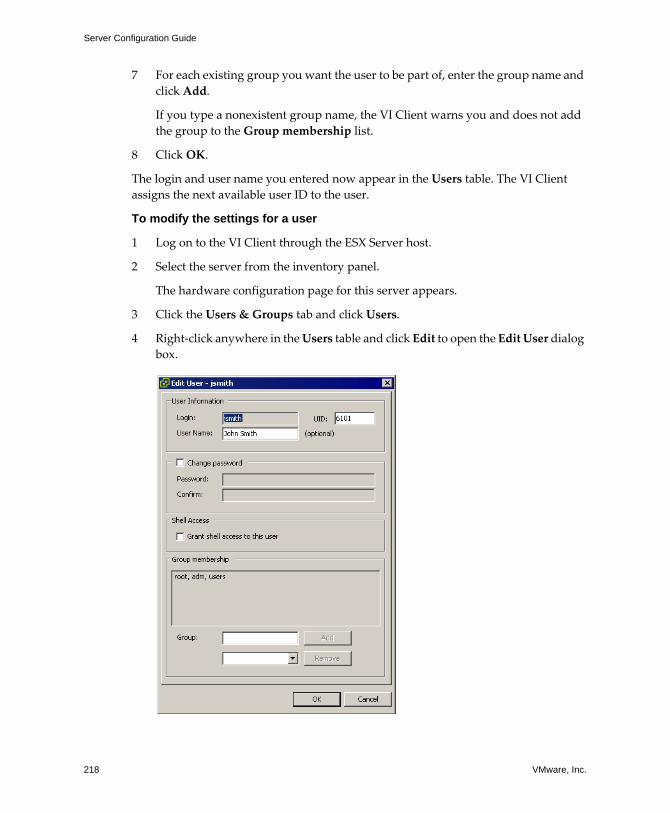
Server Configuration Guide
218 VMware, Inc.
7 For each existing group you want the user to be part of, enter the group name and click Add.
If you type a nonexistent group name, the VI Client warns you and does not add the group to the Group membership list.
8 Click OK.
The login and user name you entered now appear in the Users table. The VI Client assigns the next available user ID to the user.
To modify the settings for a user
1 Log on to the VI Client through the ESX Server host.
2 Select the server from the inventory panel.
The hardware configuration page for this server appears.
3 Click the Users & Groups tab and click Users.
4 Right‐click anywhere in the Users table and click Edit to open the Edit User dialog box.
VMware, Inc. 219
Chapter 11 Authentication and User Management
5 To change the user ID, enter a numeric user UID in the UID field.
The VI Client assigns the UID when you first create the user. In most cases, this assignment doesn�t need to be changed.
6 Enter a new user name.
7 To change the user�s password, select Change Password and enter the new password.
The password should meet the length and complexity requirements outlined in �Password Restrictions� on page 240. However, the ESX Server host checks for password compliance only if you have switched to the pam_passwdqc.so plugin for authentication. The password settings in the default authentication plugin, pam_cracklib.so, are not enforced.
8 To change the user�s ability to access the ESX Server host through a command shell, select or deselect Grant shell access to this user.
9 To add the user to another group, enter the group name and click Add.
If you type a nonexistent group name, the VI Client warns you and does not add the group to the Group membership list.
10 To remove the user from a group, select the group name from the list and click Remove.
11 Click OK.
To remove a user from the ESX Server Users table
1 Log on to the VI Client through the ESX Server host.
2 Select the server from the inventory panel.
The hardware configuration page for this server appears.
3 Click the Users & Groups tab and click Users.
4 Right‐click the user you want to remove and click Remove.
CAUTION Do not remove the root user.
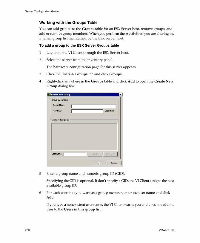
Server Configuration Guide
220 VMware, Inc.
Working with the Groups TableYou can add groups to the Groups table for an ESX Server host, remove groups, and add or remove group members. When you perform these activities, you are altering the internal group list maintained by the ESX Server host.
To add a group to the ESX Server Groups table
1 Log on to the VI Client through the ESX Server host.
2 Select the server from the inventory panel.
The hardware configuration page for this server appears.
3 Click the Users & Groups tab and click Groups.
4 Right‐click anywhere in the Groups table and click Add to open the Create New Group dialog box.
5 Enter a group name and numeric group ID (GID).
Specifying the GID is optional. If don�t specify a GID, the VI Client assigns the next available group ID.
6 For each user that you want as a group member, enter the user name and click Add.
If you type a nonexistent user name, the VI Client warns you and does not add the user to the Users in this group list.
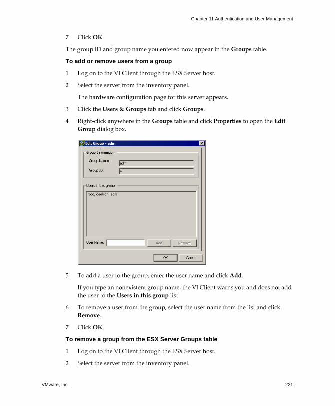
VMware, Inc. 221
Chapter 11 Authentication and User Management
7 Click OK.
The group ID and group name you entered now appear in the Groups table.
To add or remove users from a group
1 Log on to the VI Client through the ESX Server host.
2 Select the server from the inventory panel.
The hardware configuration page for this server appears.
3 Click the Users & Groups tab and click Groups.
4 Right‐click anywhere in the Groups table and click Properties to open the Edit Group dialog box.
5 To add a user to the group, enter the user name and click Add.
If you type an nonexistent group name, the VI Client warns you and does not add the user to the Users in this group list.
6 To remove a user from the group, select the user name from the list and click Remove.
7 Click OK.
To remove a group from the ESX Server Groups table
1 Log on to the VI Client through the ESX Server host.
2 Select the server from the inventory panel.
Server Configuration Guide
222 VMware, Inc.
The hardware configuration page for this server appears.
3 Click the Users & Groups tab and click Groups.
4 Right‐click the group you want to remove and click Remove.
CAUTION Do not remove the root group.
Encryption and Security Certificates for ESX ServerAll network traffic including user names passwords sent to an ESX Server host over a network connection from VirtualCenter or VI Web Access pass through port 902 or 443 respectively, and are encrypted in ESX Server by default as long as the following conditions are true:
! SSL is enabled.
! You have not changed the Web proxy service to allow unencrypted traffic for the port.
! Your service console firewall is configured for medium or high security. For information on configuring the service console firewall, see �Service Console Firewall Configuration� on page 236.
CAUTION If you disable your firewall by configuring it for low security, users can access the ESX Server host through port 8080, an insecure port. Anyone who connects to the ESX Server host through port 8080 using an authorized user name and password has access to the services on the host.
Security certificates used for encryption are created by ESX Server and stored on the host. The certificates used to secure your VirtualCenter and VI Web Access sessions are not signed by a trusted certificate authority and, therefore, do not provide the authentication security you might need in a production environment. For example, self‐signed certificates are vulnerable to man‐in‐the‐middle attacks. If you intend to use encrypted remote connections externally, consider purchasing a certificate from a trusted certificate authority or use your own security certificate for your SSL connections.
The default location for your certificate is /etc/vmware/ssl/ on the ESX Server host. The certificate consists of two files: the certificate itself (rui.crt) and the private key file (rui.key).
VMware, Inc. 223
Chapter 11 Authentication and User Management
Adding Certificates and Modifying ESX Server Web Proxy Settings
In adding certificates for ESX Server and thinking about encryption and user security, be aware of the following:
! ESX Server doesn�t handle pass phrases, also known as encrypted keys. If you set up a pass phrase, ESX Server processes will be unable to start correctly, so avoid setting up certificates using pass phrases.
! You can configure the Web proxy so that it searches for certificates in a location other than the default location. This capability proves useful for companies that prefer to centralize their certificates on a single machine so the certificates can be used by multiple hosts.
CAUTION If you store certificates in a location other the ESX Server host, you will be unable to use the certificates if the host loses network connectivity with the machine storing the certificates.
! To support encryption for user names, passwords, and packets, SSL is enabled by default for VI Web Access and Web SDK connections. If you want to configure the these connections so that they don�t encrypt transmissions, disable SSL for your VI Web Access connection or Web SDK connection by switching the connection from HTTP to HTTPS as described in �To change security settings for a Web proxy service� on page 224. Consider disabling SSL only if you have created a fully trusted environment for these clients, meaning that firewalls are in place and transmissions to and from the host are fully isolated. Disabling SSL can improve performance for VI Web Access because you avoid the overhead required to perform encryption.
! To protect against misuse of ESX Server services such as the internal Web server that hosts VI Web Access, most internal ESX Server services are accessible only through port 443, the port used for HTTPS transmission. Port 443 acts as a reverse proxy for ESX Server. You can see a list of services on ESX Server through an HTTP welcome page, but you can�t directly access these services without proper authorization. You can change this configuration so that individual services are directly accessible through HTTP connections. VMware recommends that you not make this change unless you are using ESX Server in a fully trusted environment.
! When you upgrade VirtualCenter and VI Web Access, the certificate remains in place. If you remove VirtualCenter and VI Web Access, the certificate directory is not removed from the service console.
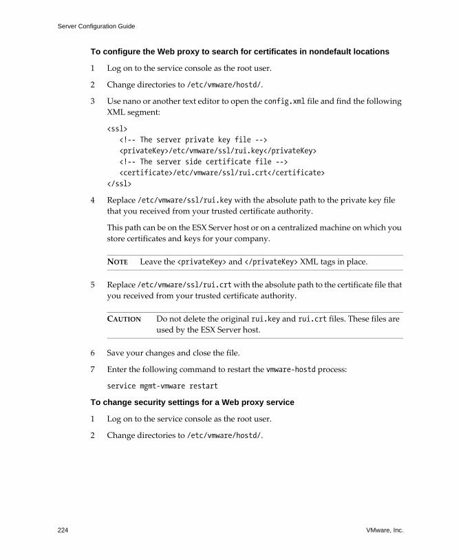
Server Configuration Guide
224 VMware, Inc.
To configure the Web proxy to search for certificates in nondefault locations
1 Log on to the service console as the root user.
2 Change directories to /etc/vmware/hostd/.
3 Use nano or another text editor to open the config.xml file and find the following XML segment:
<ssl><!-- The server private key file --><privateKey>/etc/vmware/ssl/rui.key</privateKey><!-- The server side certificate file --><certificate>/etc/vmware/ssl/rui.crt</certificate>
</ssl>
4 Replace /etc/vmware/ssl/rui.key with the absolute path to the private key file that you received from your trusted certificate authority.
This path can be on the ESX Server host or on a centralized machine on which you store certificates and keys for your company.
NOTE Leave the <privateKey> and </privateKey> XML tags in place.
5 Replace /etc/vmware/ssl/rui.crt with the absolute path to the certificate file that you received from your trusted certificate authority.
CAUTION Do not delete the original rui.key and rui.crt files. These files are used by the ESX Server host.
6 Save your changes and close the file.
7 Enter the following command to restart the vmware-hostd process:
service mgmt-vmware restart
To change security settings for a Web proxy service
1 Log on to the service console as the root user.
2 Change directories to /etc/vmware/hostd/.
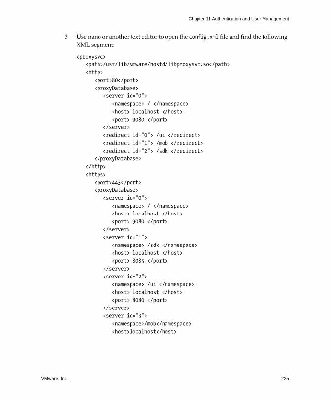
VMware, Inc. 225
Chapter 11 Authentication and User Management
3 Use nano or another text editor to open the config.xml file and find the following XML segment:
<proxysvc><path>/usr/lib/vmware/hostd/libproxysvc.so</path><http>
<port>80</port><proxyDatabase>
<server id="0"><namespace> / </namespace><host> localhost </host><port> 9080 </port>
</server><redirect id="0"> /ui </redirect><redirect id="1"> /mob </redirect><redirect id="2"> /sdk </redirect>
</proxyDatabase></http><https>
<port>443</port><proxyDatabase>
<server id="0"><namespace> / </namespace><host> localhost </host><port> 9080 </port>
</server><server id="1">
<namespace> /sdk </namespace><host> localhost </host><port> 8085 </port>
</server><server id="2">
<namespace> /ui </namespace><host> localhost </host><port> 8080 </port>
</server><server id="3">
<namespace>/mob</namespace><host>localhost</host>
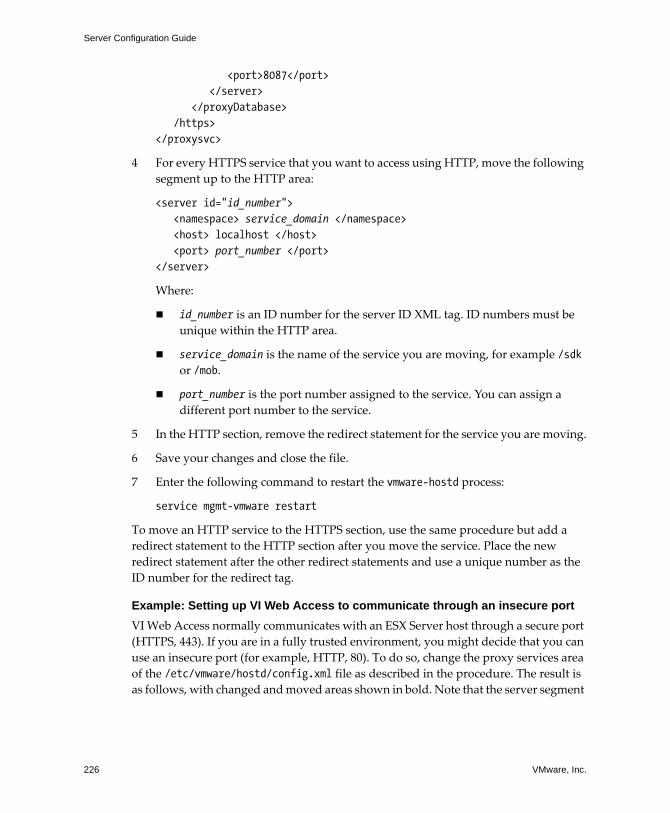
Server Configuration Guide
226 VMware, Inc.
<port>8087</port></server>
</proxyDatabase>/https>
</proxysvc>
4 For every HTTPS service that you want to access using HTTP, move the following segment up to the HTTP area:
<server id="id_number"><namespace> service_domain </namespace><host> localhost </host><port> port_number </port>
</server>
Where:
! id_number is an ID number for the server ID XML tag. ID numbers must be unique within the HTTP area.
! service_domain is the name of the service you are moving, for example /sdk or /mob.
! port_number is the port number assigned to the service. You can assign a different port number to the service.
5 In the HTTP section, remove the redirect statement for the service you are moving.
6 Save your changes and close the file.
7 Enter the following command to restart the vmware-hostd process:
service mgmt-vmware restart
To move an HTTP service to the HTTPS section, use the same procedure but add a redirect statement to the HTTP section after you move the service. Place the new redirect statement after the other redirect statements and use a unique number as the ID number for the redirect tag.
Example: Setting up VI Web Access to communicate through an insecure portVI Web Access normally communicates with an ESX Server host through a secure port (HTTPS, 443). If you are in a fully trusted environment, you might decide that you can use an insecure port (for example, HTTP, 80). To do so, change the proxy services area of the /etc/vmware/hostd/config.xml file as described in the procedure. The result is as follows, with changed and moved areas shown in bold. Note that the server segment
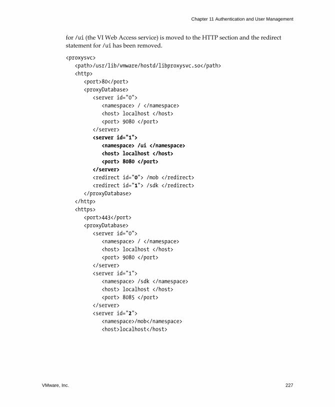
VMware, Inc. 227
Chapter 11 Authentication and User Management
for /ui (the VI Web Access service) is moved to the HTTP section and the redirect statement for /ui has been removed.
<proxysvc><path>/usr/lib/vmware/hostd/libproxysvc.so</path><http>
<port>80</port><proxyDatabase>
<server id="0"><namespace> / </namespace><host> localhost </host><port> 9080 </port>
</server><server id="1">
<namespace> /ui </namespace><host> localhost </host><port> 8080 </port>
</server><redirect id="0"> /mob </redirect><redirect id="1"> /sdk </redirect>
</proxyDatabase></http><https>
<port>443</port><proxyDatabase>
<server id="0"><namespace> / </namespace><host> localhost </host><port> 9080 </port>
</server><server id="1">
<namespace> /sdk </namespace><host> localhost </host><port> 8085 </port>
</server><server id="2">
<namespace>/mob</namespace><host>localhost</host>
Server Configuration Guide
228 VMware, Inc.
<port>8087</port></server>
</proxyDatabase></https>
</proxysvc>
Regenerating Certificates The ESX Server host generates certificates when you first start the host after installation. Thereafter, whenever you restart the vmware-hostd process, the vmware-mgmt script searches for existing certificate files (rui.crt and rui.key) and, if it can�t find them, generates new certificate files.
Under certain circumstances, you might need to force ESX Server host to generate new certificates. You typically need to generate new certificates only if:
! You change the host name.
! You accidentally delete the certificates.
To generate new Certificates for the ESX Server host
1 Change directories to /etc/vmware/ssl.
2 Create backups of any existing certificates by executing the following commands:
mv rui.crt orig.rui.crtmv rui.key orig.rui.key
NOTE If you are regenerating certificates because you accidentally deleted your certificates, you do not need to complete the backup step.
3 Enter the following command to restart the vmware-hostd process:
service mgmt-vmware restart
4 Confirm that the ESX Server host generated new certificates by executing the following command comparing the time stamps of the new certificate files with orig.rui.crt and orig.rui.key:
ls -la
VMware, Inc. 229
Chapter 11 Authentication and User Management
Virtual Machine Delegates for NFS StorageTo perform most activities on virtual machines, an ESX Server needs access to virtual machine files. For instance, to power on and off virtual machines the ESX Server must be able to create, manipulate, and delete files on the volume that is storing the virtual disk files.
If you are creating, configuring, or administering virtual machines on an NFS datastore you do so through a special user, known as the delegate user. The delegate userʹs identity is used by the ESX Server for all I/O requests issued to the underlying file system.
By default, the delegate user for the ESX Server host is root. However, having root as the delegate user may not work for all NFS datastores. NFS administrators may export volumes with root squashing enabled. The root squash feature maps root to a user with no significant privileges on the NFS server, limiting the root userʹs abilities. This feature is commonly used to prevent unauthorized access to files on an NFS volume. If the NFS volume was exported with root squash enabled, the NFS server might refuse access to the ESX Server host. To ensure that you can create and manage virtual machines from your host, the NFS administrator must turn off the root squash feature or add the ESX Server host�s physical network adapter to the list of trusted servers.
If the NFS administrator is unwilling to take either of these actions, you can change the delegate user to a different identity through experimental ESX Server functionality. This identity must match the owner of the directory on the NFS server otherwise the ESX Server host will be unable to perform file level operations. To set up a different identity for the delegate user, acquire the following information:
! User name of the directory owner
! User ID (UID) of the directory owner
! Group ID (GID) of the directory owner
Then, use this information to change the delegate user setting for the ESX Server host so that it matches the owner of the directory, enabling NFS datastore to recognize the ESX Server host correctly. The delegate user is configured globally, and the same identity is used to access to every volume.
Server Configuration Guide
230 VMware, Inc.
Setting up the delegate user on an ESX Server host requires that you complete these activities:
! From the Users & Groups tab for a VI Client running directly on the ESX Server host, either:
! Edit the user named vimuser to add the correct UID and GID. vimuser is an ESX Server host user provided to you as a convenience for setting up delegate users. By default, vimuser has a UID of 12 and a GID of 20.
! Add a completely new user to the ESX Server host with the delegate user name, UID, and GID.
You must perform one of these steps regardless of whether you manage the host through a direct connection or through the VirtualCenter Server. Also, you need to make sure that the delegate user (vimuser or a delegate user you create) is identical across all ESX Server hosts that use the NFS datastore. For information on adding users, see �Working with the Users Table� on page 216.
! Configure a virtual machine delegate as part of the security profile for the host, as described in the procedure that follows.
You configure the security profile through VirtualCenter or through a VI Client running directly on the ESX Server host. Performing this task through VirtualCenter is more efficient because you can work through each host one‐by‐one in the same session. In this case, the users that can access NFS volumes are those that are in the Windows domain.
WARNING Changing the delegate user for an ESX Server host is experimental and, currently, VMware does not support this implementation. Use of this functional may result in unexpected behavior.
To change the virtual machine delegate
1 Log on to the VI Client through the ESX Server host.
2 Select the server from the inventory panel.
The hardware configuration page for this server appears with the Summary tab displayed.
3 Click Enter Maintenance Mode.
4 Click the Configuration tab and click Security Profile.
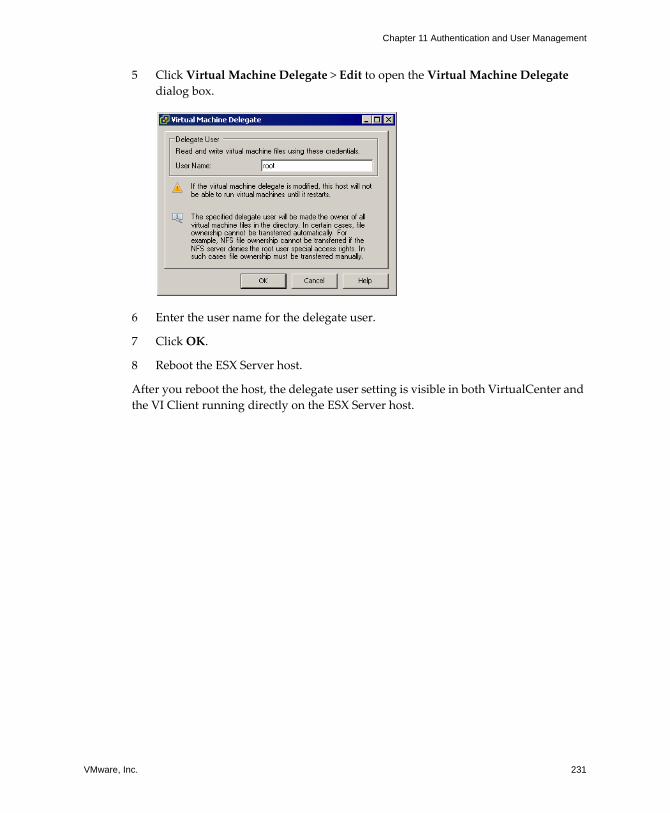
VMware, Inc. 231
Chapter 11 Authentication and User Management
5 Click Virtual Machine Delegate > Edit to open the Virtual Machine Delegate dialog box.
6 Enter the user name for the delegate user.
7 Click OK.
8 Reboot the ESX Server host.
After you reboot the host, the delegate user setting is visible in both VirtualCenter and the VI Client running directly on the ESX Server host.

Server Configuration Guide
232 VMware, Inc.

VMware, Inc. 233
CHAPTER 12 Service Console Security
This chapter makes basic security recommendations for using the service console and explains some of the service console�s built‐in security features. The service console is a management interface to ESX Server and, as such, its security is critical. To protect the service console against unauthorized intrusion and misuse, VMware imposes constraints on several service console parameters, settings, and activities.
These constraints are designed to raise the security level for ESX Server. You can loosen them to meet your particular configuration needs, but if you do so, make sure you are working in a trusted environment and have taken enough other security measures to protect the network as a whole and the devices connected to the ESX Server host.
This chapter covers the following topics:
! �General Security Recommendations� on page 234
! �Service Console Firewall Configuration� on page 236
! �Password Restrictions� on page 240
! �Cipher Strength� on page 248
! �setuid and setgid Applications� on page 249
! �SSH Security� on page 252
! �Security Patches and Security Vulnerability Scanning Software� on page 253
Server Configuration Guide
234 VMware, Inc.
General Security RecommendationsConsider the following recommendations when evaluating service console security and administering the service console:
! Install antivirus software.
Even though you can run an ESX Server host without connecting the service console to any network, most implementations allow network access to the service console. Because the service console is a full operating system, you should protect it from viruses, just as you would a standard operating system or virtual machine at your site. If youʹre already using Linux antivirus software in your organization, you can install the same antivirus software on the service console. You can also install third‐party intrusion and root kit detection software such as Tripwire.
NOTE Antivirus software can affect performance. If you are confident that the ESX Server host is operating in a fully trusted environment, you can balance the need for this security measure against performance costs.
! Limit user access.
To improve security, restrict user access to the service console and enforce access security policies like setting up password restrictions�for example, character length, password aging limits, and use of a grub password for booting the host.
The service console has privileged access to certain parts of ESX Server. Therefore, only trusted users should be provided logon access. By default, root access is limited by not allowing secure shell (SSH) logon as root, and you should strongly consider keeping this default. ESX Server system administrators should be required to log on as regular users and then use sudo to perform specific tasks that require root privileges.
Also, try to run as few processes on the service console as possible. Ideally, you should strive to run only the processes, services, and agents that you absolutely need such as virus checkers, virtual machine backups, and so forth.
! Use VI Client to administer your ESX Server hosts.
Whenever possible, use VI Client, VI Web Access, or a third‐party network management tool to administer your ESX Server hosts instead of working though the command line interface as root. Using VI Client lets you limit the accounts with access to the service console, safely delegate responsibilities, and set up roles that prevent administrators and users from using capabilities they don�t need.
VMware, Inc. 235
Chapter 12 Service Console Security
! Use only VMware sources to upgrade ESX Server components you run on the service console.
The service console runs a variety of third‐party packages such as the Tomcat Web service to support management interfaces or tasks that you need to perform. VMware does not support upgrading these packages from anything other than a VMware source. If you use a download or patch from another source, you might compromise service console security or functions. Regularly check third‐party vendor sites and the VMware knowledge base for security alerts.
Logging On to the Service ConsoleAlthough you perform most ESX Server configuration activities through the VI Client, you use the service console command‐line interface when configuring certain security features. Using the command line interface requires that you log on to the host. If you have direct access to the ESX Server host, you can log on to the physical console on that machine. To do so, press Alt‐F2 to open the login screen. For remote connections, use SSH or another remote console connection to start a session on the host.
Whether you access the service console locally or through a remote connection such as SSH, you must log on using a user name and password recognized by the ESX Server host. For information on user names and passwords for ESX Server hosts, see �Working with Users and Groups on ESX Server Hosts� on page 214.
If you are logging onto the host to perform activities that require root privileges, you should log on to the service console as a recognized user and acquire root privileges through the su command or, preferably, the sudo command. The sudo command enhances security because it grants root privileges only for select activities in contrast to the su command, which grants root privileges for all activities. Using sudo also provides superior accountability because all sudo activities are logged, whereas if you use su, ESX Server only logs the fact that the user switched to root by way of su.
In addition to ESX‐specific commands, you can use the service console command‐line interface to execute many Linux and Unix commands. For detailed usage notes on service console commands, use the man <command_name> command to check for man pages.
Server Configuration Guide
236 VMware, Inc.
Service Console Firewall ConfigurationESX Server includes a firewall between the service console and the network. To ensure the integrity of the service console, VMware has reduced the number of firewall ports that are open by default. At installation time, the service console firewall is configured to block all incoming and outgoing traffic except for that on ports 902, 80, 443, and 22, which are used for basic communication with ESX Server. This setting enforces a high level of security for your ESX Server host.
NOTE The firewall also allows Internet Control Message Protocol (ICMP) pings and communication with DHCP and DNS (UDP only) clients.
In trusted environments, you might decide that a lower security level is acceptable. If so, you can set the firewall for either medium or low security:
! Medium security � All incoming traffic is blocked except on the default ports (902, 433, 80, and 22) and any ports you specifically open. Outgoing traffic is not blocked.
! Low security � There are no blocks on either incoming or outgoing traffic. This setting is equivalent to removing the firewall.
Because the ports open by default are strictly limited, you might need to open additional ports after installation. For a list of commonly used ports you might need to open, see �TCP and UDP Ports for Management Access� on page 180.
Be aware that as you add the supported services and management agents required to operate ESX Server effectively, you open other ports in the service console firewall. You add services and management agents through VirtualCenter as described in �Opening Firewall Ports for Supported Services and Management Agents� on page 185.
In addition to the ports you open for these services and agents, you might need to open other ports when you configure certain devices, services, or agents such as storage devices, backup agents, and management agents. For example, if you are using Veritas NetBackup� 4.5 as a backup agent, you need to open ports 13720, 13724, 13782, and 13783, which NetBackup uses for client‐media transactions, database backups, user backups or restores, and so forth. Refer to vendor specifications for the device, service, or agent to determine which ports to open.
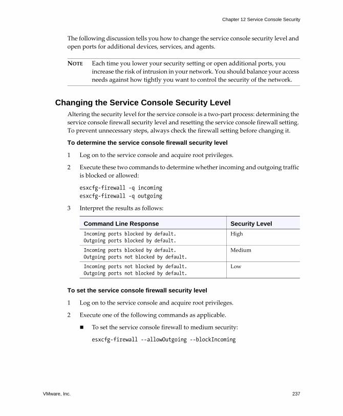
VMware, Inc. 237
Chapter 12 Service Console Security
The following discussion tells you how to change the service console security level and open ports for additional devices, services, and agents.
NOTE Each time you lower your security setting or open additional ports, you increase the risk of intrusion in your network. You should balance your access needs against how tightly you want to control the security of the network.
Changing the Service Console Security LevelAltering the security level for the service console is a two‐part process: determining the service console firewall security level and resetting the service console firewall setting. To prevent unnecessary steps, always check the firewall setting before changing it.
To determine the service console firewall security level
1 Log on to the service console and acquire root privileges.
2 Execute these two commands to determine whether incoming and outgoing traffic is blocked or allowed:
esxcfg-firewall -q incomingesxcfg-firewall -q outgoing
3 Interpret the results as follows:
To set the service console firewall security level
1 Log on to the service console and acquire root privileges.
2 Execute one of the following commands as applicable.
! To set the service console firewall to medium security:
esxcfg-firewall --allowOutgoing --blockIncoming
Command Line Response Security LevelIncoming ports blocked by default. Outgoing ports blocked by default.
High
Incoming ports blocked by default.Outgoing ports not blocked by default.
Medium
Incoming ports not blocked by default.Outgoing ports not blocked by default.
Low
Server Configuration Guide
238 VMware, Inc.
! To set the virtual firewall to low security:
esxcfg-firewall --allowIncoming --allowOutgoing
CAUTION Using the above command disables all firewall protection.
! To return the service console firewall to high security:
esxcfg-firewall --blockIncoming --blockOutgoing
3 Execute the following command to restart the vmware-hostd process:
service mgmt-vmware restart
Changing the service console firewall security level does not affect existing connections. For example, if the firewall is set to low security and a backup is running on a port you didn�t explicitly open, raising the firewall setting to high does not terminate the backup. Rather, because the firewall is configured to pass packets for previously established connections, the backup completes, releases the connection, and no further connections are accepted for the port.
Opening and Closing Ports in the Service Console FirewallYou can open service console firewall ports when you install third‐party devices, services, and agents. Before you open ports to support the item you are installing, refer to vendor specifications to determine the necessary ports.
If you close a port, active sessions of the service associated with the port are not automatically disconnected when you close the port. For example, if a backup is executing and you close the port for the backup agent, the backup continues until it completes and the agent releases the connection.
Perform the following procedures only if you are opening or closing ports for services or agents not specifically configurable through the VI CLient. For information on configuring additional ports in VirtualCenter, see �Opening Firewall Ports for Supported Services and Management Agents� on page 185.
WARNING VMware supports opening and closing firewall ports only through the VI Client or the esxcfg-firewall command, as described below. Using any other methods or scripts to open and close firewall ports can lead to unexpected behavior.
VMware, Inc. 239
Chapter 12 Service Console Security
To open a specific port in the service console firewall
1 Log on to the service console and acquire root privileges.
2 Execute this command:
esxcfg-firewall --openPort <port_number>,tcp|udp,in|out,<port_name>
Where:
! port_number is the vendor‐specified port number.
! tcp|udp is the protocol. Select tcp for TCP traffic or udp for UDP traffic.
! in|out is the traffic direction. Select in to open the port for inbound traffic or out to open it for outbound traffic.
! port_name is a descriptive name. The name does not need to be unique, but it should be meaningful to help identify the service or agent using the port.
For example:
esxcfg-firewall --openPort 6380,tcp,in,Navisphere
3 Execute the following command to restart the vmware-hostd process:
service mgmt-vmware restart
To close a specific port in the service console firewall
1 Log on to the service console and acquire root privileges.
2 Execute this command:
esxcfg-firewall -closePort <port_number>,tcp|udp,in|out,<port_name>
The port_name argument is optional for -closePort.
For example:
esxcfg-firewall --closePort 6380,tcp,in
3 Execute the following command to restart the vmware-hostd process:
service mgmt-vmware restart
You can use the -closepPort option to close only those ports that you opened with the -openPort option. If you used a different method to open the port, you need to use an equivalent method to close it. For example, you can close the SSH port (22) only by disabling the SSH Server incoming connection and SSH Client outgoing connection in the VI Client. For information on opening and closing ports through the VI Client, see �Opening Firewall Ports for Supported Services and Management Agents� on page 185.

Server Configuration Guide
240 VMware, Inc.
Password RestrictionsThe ease with which an attacker can log on to an ESX Server host depends on his or her ability to find a legitimate user name/password combination. A malicious user can obtain a password in a number of ways. For example, an attacker can sniff insecure network traffic, such as Telnet or FTP transmissions, for successful logon attempts.
Another common method is to crack the password by running a password generator. Passwords generators are useful for mounting various kinds of password attacks, including brute force attacks, in which the generator tries every character combination up to a certain password length, and dictionary attacks, in which the generator tries real words and simple mutations of real words.
Implementing restrictions that govern the length, character sets, and duration of passwords can make attacks initiated by a password generator far more difficult. The longer and more complex the password, the harder it is for an attacker to discover. The more often users have to change passwords, the more difficult it is to find a password that works repeatably.
NOTE Always consider the human factor when deciding how to implement password restrictions. If you make passwords too hard to remember or enforce frequent password changes, your users might be inclined to write down their passwords, thus eliminating any benefit.
To help protect your password database from misuse, password shadowing is enabled for ESX Server so that password hashes are hidden from access. Also, ESX Server uses MD5 password hashes, which provide stronger password security and let you set minimum length requirements to more than 8 characters.
ESX Server provides password controls on two levels to help you enforce password policies for your users and limit the risk of password cracking:
! Password aging � These controls govern how long a user password can be active before the user is required to change it. They help ensure that passwords change often enough so that if an attacker obtains a password through sniffing or social engineering, he or she cannot keep accessing ESX Server indefinitely.
! Password complexity � These controls ensure that the users select passwords that are hard for password generators to determine.
VMware, Inc. 241
Chapter 12 Service Console Security
Password AgingTo ensure that passwords don�t stay active for long periods, ESX Server imposes the following password aging restrictions for user logons by default:
! Maximum days � The number of days that a user can keep a password before it needs to be changed. The default setting for ESX Server is 90 days. By default, the root account and other service accounts are exempt from the 90 day expiration.
! Minimum days � The minimum number of days between password changes. The default setting is 0, meaning that the users can change their passwords any time.
! Warning time � The number of days in advance of password expiration that ESX Server observes when issuing a password change reminder. The default setting is 7 days. Warnings are only displayed when logging directly onto the service console or when using SSH.
You can tighten or loosen any of these settings by executing esxcfg-auth command options. If you need to override the default password aging settings for an individual user, use the chage command.
To change default password aging restrictions for ESX Server
1 Log on to the service console and acquire root privileges.
2 Execute one or more of the following commands as applicable.
! To change maximum number of days a user can keep a password:
esxcfg-auth --passmaxdays=<number_of_days>
Where <number_of_days> is the maximum number of days before password expiration.
! To change minimum number of days between password changes:
esxcfg-auth --passmindays=<number_of_days>
Where <number_of_days> is the minimum number of days between password changes.
! To change warning time before a password change:
esxcfg-auth --passwarnage=<number_of_days>
Where <number_of_days> is the number of days of advanced warning a user receives before a password change is due.
Server Configuration Guide
242 VMware, Inc.
To override default password aging restrictions for individual users or groups
1 Log on to the service console and acquire root privileges.
2 Execute one or more of the following commands as applicable.
! To specify a new maximum days value:
chage -M <number_of_days> <username>
! To specify a new minimum days value:
chage -m <number_of_days> <username>
! To specify a new warning time value:
chage -W <number_of_days> <username>
You can use the man chage command to learn about other chage options.
Password ComplexityBy default, ESX Server uses the pam_cracklib.so plugin to set the rules that users must observe when creating passwords and to check password strength during the creation process.
The pam_cracklib.so plugin lets you determine the basic standards that all passwords must meet. By default, ESX Server imposes no restrictions on the root password. However, when non‐root users attempt to change their passwords, the passwords they choose must meet the basic standards set by pam_cracklib.so. In addition, non‐root users can make only a certain number of password change attempts before pam_cracklib.so begins issuing messages and eventually closes the password change screen. The ESX Server defaults for pam_cracklib.so password standards and retry restrictions are as follows:
! Minimum length � The pam_cracklib.so minimum length parameter for ESX Server systems is set to 9. This means that the user must enter at least 8 characters if he or she uses only one character class (lowercase, uppercase, digit, or other).
The password length algorithm allows shorter passwords if the user enters a mix of character classes. To calculate the actual character length a user needs to enter
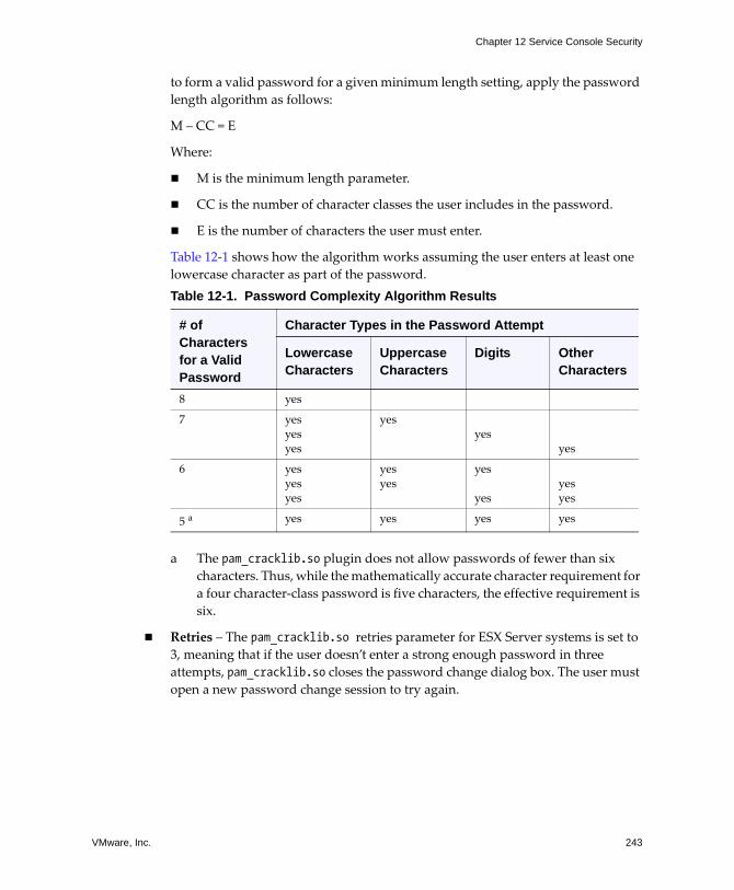
VMware, Inc. 243
Chapter 12 Service Console Security
to form a valid password for a given minimum length setting, apply the password length algorithm as follows:
M � CC = E
Where:
! M is the minimum length parameter.
! CC is the number of character classes the user includes in the password.
! E is the number of characters the user must enter.
Table 12‐1 shows how the algorithm works assuming the user enters at least one lowercase character as part of the password.
a The pam_cracklib.so plugin does not allow passwords of fewer than six characters. Thus, while the mathematically accurate character requirement for a four character‐class password is five characters, the effective requirement is six.
! Retries � The pam_cracklib.so retries parameter for ESX Server systems is set to 3, meaning that if the user doesn�t enter a strong enough password in three attempts, pam_cracklib.so closes the password change dialog box. The user must open a new password change session to try again.
Table 12-1. Password Complexity Algorithm Results
# of Characters for a Valid Password
Character Types in the Password Attempt
Lowercase Characters
Uppercase Characters
Digits Other Characters
8 yes
7 yesyesyes
yesyes
yes
6 yesyesyes
yesyes
yes
yesyesyes
5 a yes yes yes yes
Server Configuration Guide
244 VMware, Inc.
The pam_cracklib.so plugin checks all password change attempts to ensure that passwords meet the following strength criteria:
! The new password must not be a palindrome�a password where the characters mirror each other around a central letter, as in radar or civic.
! The new password must not be the reverse of the old password.
! The new password must not be a rotation�a version of the old password in which one or more characters have been rotated to the front or back of the password string.
! The new password must differ from the old password by more than a change of case.
! The new password must differ from the old password by more than a few characters.
! The new password must not have been used in the past. The pam_cracklib.so plugin applies this criterion only If you have configured a password reuse rule.
By default ESX Server does not enforce any password reuse rules, so ordinarily the pam_cracklib.so plugin never rejects a password change attempt on these grounds. However, you can configure a reuse rule to ensure that your users don�t alternate between a few passwords.
If you configure a reuse rule, old passwords are stored in a file that the pam_cracklib.so plugin references during each password change attempt. The number of old passwords that ESX Server retains is determined by the reuse rule. When a user has created enough passwords to reach the value specified in the reuse rule, old passwords are removed from the file in age order. To learn how to configure a reuse rule, see �To configure a password reuse rule� on page 245.
! The new password must be long enough and complex enough. You configure these requirements by changing the pam_cracklib.so complexity parameters with the esxcfg-auth command, which lets you set the number of retries, the minimum password length, and a variety of character credits. Character credits let the user enter shorter passwords if they include more character types in the password. To learn how to configure password length and complexity, see �To change default password complexity for the pam_cracklib.so plugin� on page 246.
For more information on the pam_cracklib.so plugin, see your Linux documentation.
NOTE The pam_cracklib.so plugin used in Linux provides more parameters than the ones supported for ESX Server. You cannot specify these additional parameters in esxcfg-auth.
VMware, Inc. 245
Chapter 12 Service Console Security
To configure a password reuse rule
1 Log on to the service console and acquire root privileges.
2 Change directories by entering cd /etc/pam.d/ at the command prompt.
3 Use nano or another text editor to open the system-auth file.
4 Locate the line that starts with:
password sufficient /lib/security/$ISA/pam_unix.so
5 Add the following parameters to the end of the line:
remember=X
Where X is the number of old passwords you want ESX Server to store for each user. Use a space as the delimiter between remember=X and the preceding parameter.
6 Save your changes and close the file.
7 Change directories to /etc/security/, and issue the following command to make a zero length file with opasswd as the filename:
touch opasswd
8 Issue the following commands:
chmod 0600 opasswdchown root:root /etc/security/opasswd
Server Configuration Guide
246 VMware, Inc.
To change default password complexity for the pam_cracklib.so plugin
1 Log on to the service console and acquire root privileges.
2 Enter the following command:
esxcfg-auth --usecrack=<retries> <minimum_length> <lc_credit> <uc_credit> <d_credit> <oc_credit>
Where:
! retries is the number of retries the user is allowed before ESX Server locks him or her out of password change mode.
! minimum_length is the minimum number of characters a user must enter to make the password acceptable. This number is the total length before any length credits are applied.
One length credit is always applied so, in effect, the password length is one character less than the minimum_length parameter you specify. Because the pam_cracklib.so plugin does not accept passwords of less than 6 characters, calculate the minimum_length parameter so that users can�t drop the password length below 6 as a result of subtracting the length credits.
! lc_credit is the number by which the minimum_length parameter is reduced if the user includes at least one lower case character in the password.
! uc_credit is the number by which the minimum_length parameter is reduced if the user includes at least one upper case character.
! d_credit is the number by which the minimum_length parameter is reduced if the user includes at least one digit.
! oc_credit is the number by which the minimum_length parameter is reduced if the user includes at least one special character, such as an underscore or dash.
Enter character credit parameters as a positive number or as 0 if you do not want the plugin to give the user credit for including this character class. Character credits are additive. The more different types of characters the user enters, the fewer characters are required to form a valid password. For example, you issue the following command:
esxcfg-auth --usecrack=3 11 1 1 1 2
With this setting in effect, a user creating a password that contains lowercase characters and one underscore would need eight characters to create a valid password. If the user decided to include all types of characters (lowercase alphabetical, uppercase alphabetical, numeric, and special), he or she would need only six characters.
VMware, Inc. 247
Chapter 12 Service Console Security
Changing the Password PluginThe pam_cracklib.so plugin provides sufficient password strength enforcement for most environments. However, if the pam_cracklib.so plugin is not stringent enough for your needs, you can use the pam_passwdqc.so plugin instead. You change the plugin through the esxcfg-auth command.
The pam_passwdqc.so plugin tests for the same password characteristics as the pam_cracklib.so plugin. However, it provides a greater number of options for fine‐tuning password strength and performs password strength tests for all users, including the root user. The pam_passwdqc.so plugin is also somewhat more difficult to use than the pam_cracklib.so plugin. For more information on this plugin, see your Linux documentation.
NOTE The pam_passwdqc.so plugin used in Linux provides more parameters than the ones supported for ESX Server. You cannot specify these additional parameters in esxcfg-auth.
To switch to the pam_passwdqc.so plugin
1 Log on to the service console and acquire root privileges.
2 Enter the following command:
esxcfg-auth --usepamqc=<N0> <N1> <N2> <N3> <N4> <match>
Where:
! N0 is the number of characters required for a password that uses characters from only one character class.
! N1 is the number of characters required for a password that uses characters from two character classes.
! N2 is used for passphrases. ESX Server requires three words for a passphrase.
! N3 is the number of characters required for a password that uses characters from three character classes.
! N4 is the number of characters required for a password that uses characters from all four character classes.
! match is the number of characters allowed in a string that is reused from the old password. If the pam_passwdqc.so plugin finds a reused string of this length or longer, it disqualifies the string from the strength test and uses only the remaining characters.
Server Configuration Guide
248 VMware, Inc.
Setting any of these options to ‐1 directs the pam_passwdqc.so plugin to ignore the requirement. Setting any of these options to disabled directs the pam_passwdqc.so plugin to disqualify passwords with the associated characteristic. The values used must be in descending order except for -1 and disabled.
For example, you issue the following command:
esxcfg-auth --usepamqc=disabled 18 -1 12 8
With this setting in effect, a user creating a password would never be able to set passwords that contain only one character class. He or she would need to use at least 18 characters for a password with two‐character class, 12 characters for a three‐character class password, and eight characters for four‐character class passwords. Attempts to create passphrases would be ignored.
Cipher StrengthTransmitting data over insecure connections presents a security risk because malicious users might be able to scan data as it travels through the network. As a safeguard, network components commonly encrypt the data so that it can�t be easily read. To encrypt data, the sending component, such as a gateway or redirector, applies algorithms, or ciphers, to alter the data before transmitting it. The receiving component uses a key to decrypt the data, returning it to its original form.
Several different ciphers are currently in use, and the level of security provided by each is different. One measure of a cipher�s ability to protect data is its cipher strength�the number of bits in the encryption key. The larger the number, the more secure the cipher.
To ensure the protection of the data transmitted to and from external network connections, ESX Server uses one of the strongest block ciphers available�256‐bit AES block encryption. ESX Server also uses 1024‐bit RSA for key exchange. These encryption algorithms are the default for the following connections:
! VI Client connections to the VirtualCenter Server and to the ESX Server host through the service console.
! VI Web Access connections to the ESX Server host through the service console.
NOTE Because VI Web Access cipher usage is determined by the Web browser you are using, this management tool might use other ciphers.
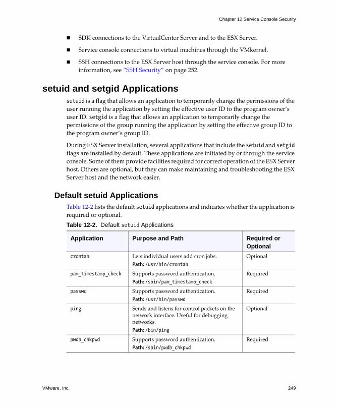
VMware, Inc. 249
Chapter 12 Service Console Security
! SDK connections to the VirtualCenter Server and to the ESX Server.
! Service console connections to virtual machines through the VMkernel.
! SSH connections to the ESX Server host through the service console. For more information, see �SSH Security� on page 252.
setuid and setgid Applicationssetuid is a flag that allows an application to temporarily change the permissions of the user running the application by setting the effective user ID to the program owner�s user ID. setgid is a flag that allows an application to temporarily change the permissions of the group running the application by setting the effective group ID to the program owner�s group ID.
During ESX Server installation, several applications that include the setuid and setgid flags are installed by default. These applications are initiated by or through the service console. Some of them provide facilities required for correct operation of the ESX Server host. Others are optional, but they can make maintaining and troubleshooting the ESX Server host and the network easier.
Default setuid Applications Table 12‐2 lists the default setuid applications and indicates whether the application is required or optional.Table 12-2. Default setuid Applications
Application Purpose and Path Required or Optional
crontab Lets individual users add cron jobs.Path: /usr/bin/crontab
Optional
pam_timestamp_check Supports password authentication.Path: /sbin/pam_timestamp_check
Required
passwd Supports password authentication.Path: /usr/bin/passwd
Required
ping Sends and listens for control packets on the network interface. Useful for debugging networks.Path: /bin/ping
Optional
pwdb_chkpwd Supports password authentication.Path: /sbin/pwdb_chkpwd
Required
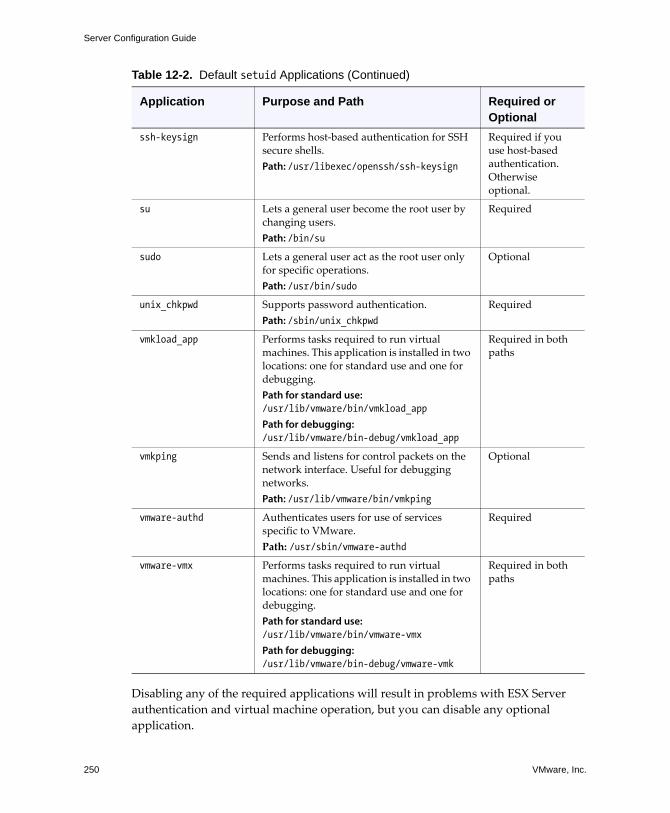
Server Configuration Guide
250 VMware, Inc.
Disabling any of the required applications will result in problems with ESX Server authentication and virtual machine operation, but you can disable any optional application.
ssh-keysign Performs host‐based authentication for SSH secure shells.Path: /usr/libexec/openssh/ssh-keysign
Required if you use host‐based authentication. Otherwise optional.
su Lets a general user become the root user by changing users.Path: /bin/su
Required
sudo Lets a general user act as the root user only for specific operations.Path: /usr/bin/sudo
Optional
unix_chkpwd Supports password authentication.Path: /sbin/unix_chkpwd
Required
vmkload_app Performs tasks required to run virtual machines. This application is installed in two locations: one for standard use and one for debugging. Path for standard use: /usr/lib/vmware/bin/vmkload_app Path for debugging: /usr/lib/vmware/bin-debug/vmkload_app
Required in both paths
vmkping Sends and listens for control packets on the network interface. Useful for debugging networks.Path: /usr/lib/vmware/bin/vmkping
Optional
vmware-authd Authenticates users for use of services specific to VMware.Path: /usr/sbin/vmware-authd
Required
vmware-vmx Performs tasks required to run virtual machines. This application is installed in two locations: one for standard use and one for debugging. Path for standard use: /usr/lib/vmware/bin/vmware-vmx Path for debugging: /usr/lib/vmware/bin-debug/vmware-vmk
Required in both paths
Table 12-2. Default setuid Applications (Continued)
Application Purpose and Path Required or Optional
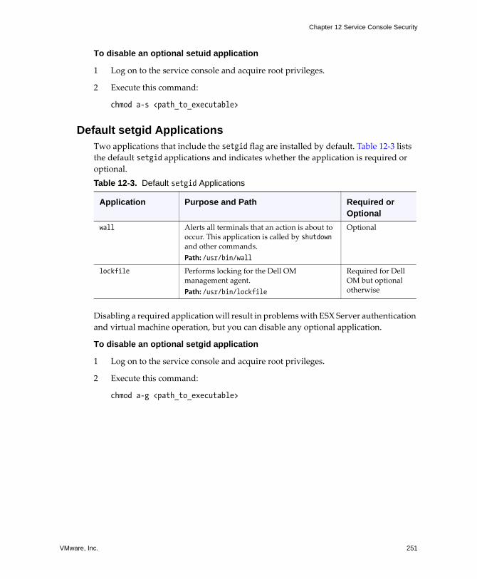
VMware, Inc. 251
Chapter 12 Service Console Security
To disable an optional setuid application
1 Log on to the service console and acquire root privileges.
2 Execute this command:
chmod a-s <path_to_executable>
Default setgid ApplicationsTwo applications that include the setgid flag are installed by default. Table 12‐3 lists the default setgid applications and indicates whether the application is required or optional.
Disabling a required application will result in problems with ESX Server authentication and virtual machine operation, but you can disable any optional application.
To disable an optional setgid application
1 Log on to the service console and acquire root privileges.
2 Execute this command:
chmod a-g <path_to_executable>
Table 12-3. Default setgid Applications
Application Purpose and Path Required or Optional
wall Alerts all terminals that an action is about to occur. This application is called by shutdown and other commands.Path: /usr/bin/wall
Optional
lockfile Performs locking for the Dell OM management agent.Path: /usr/bin/lockfile
Required for Dell OM but optional otherwise
Server Configuration Guide
252 VMware, Inc.
SSH SecuritySSH is a commonly used UNIX and Linux command shell that lets you remotely log on to the service console and perform certain management and configuration tasks for ESX Server. SSH is used for secure logons and data transfers because it offers stronger protection than other command shells. In this ESX Server release, the SSH configuration has been enhanced to provide a higher security level than in the past. Key features of this enhancement include:
! Version 1 SSH protocol disabled � VMware no longer supports Version 1 SSH protocol and uses Version 2 protocol exclusively. Version 2 eliminates certain security issues present in Version 1 and provides you with a safer communications interface to the service console.
! Improved cipher strength � SSH now supports only 256‐bit and 128‐bit AES ciphers for your connections.
! Limits on remote logons as root � You can no longer remotely log on as root. Instead, you log on as an identifiable user and either use the sudo command to execute specific operations that require root privileges or enter the su command to become the root user.
NOTE The sudo command provides security benefits in that it limits root activities and helps you check for possible misuse of root privileges by generating an audit trail of any root activities that the user performs.
These settings are designed to provide solid protection for the data you transmit to the service console through SSH. If this configuration is too rigid for your needs, you can lower security parameters.
To change the default SSH configuration
1 Log on to the service console and acquire root privileges.
2 Change directories by entering cd /etc/ssh at the command prompt.
3 Use nano or another text editor to perform any or all of following actions, as appropriate.
! To allow remote root logon, change the setting to yes in the following line in the sshd_config file:
PermitRootLogin no
VMware, Inc. 253
Chapter 12 Service Console Security
! To revert to the default SSH protocol (Version 1 and 2), comment out the following line in the sshd_config file:
Protocol 2
! To revert to the 3DES cipher and other ciphers, comment out the following line in the sshd_config file:
Ciphers aes256-cbc,aes128-cbc
! To disable Secure FTP (SFTP) on SSH, comment out the following line in the sshd_config file:
Subsystem ftp /usr/libexec/openssh/sftp-server
4 Save your changes and close the file.
5 Execute the following command to restart the SSHD service:
service sshd restart
Security Patches and Security Vulnerability Scanning Software
If a fix for a particular LINUX‐supported software package provided by VMware as a service console component�for example, a service, facility, or protocol�becomes available, VMware provides an RPM Package Manager (RPM) package that you use to update the software package on ESX Server. Although these fixes might be available from other sources, always use RPMs generated by VMware instead of using third‐party RPMs.
When providing patches for a software package, the VMware policy is to backport the fix to a version of the software known to be stable. This approach reduces the chance of introducing new problems and instability in the software. Because the patch is added to an existing version of the software, the version number of the software stays the same, but a patch number is added as a suffix.
Certain security scanners such as Nessus check the version number but not the patch suffix as they search for security holes. As a result, these scanners can falsely report that software is down‐level and doesn�t include the most recent security patches even though it does. This problem is common to the industry and not specific to VMware.
NOTE Some security scanners are able to handle this situation correctly, but they typically lag by a version or more. For example, the version of Nessus released after a Red Hat patch often doesn�t report these false positives.
Server Configuration Guide
254 VMware, Inc.
Here is an example of how this problem occurs:
1 You initially install ESX Server with OpenSSL version 0.9.7a (where 0.9.7a is the original version with no patches).
2 OpenSSL releases a patch that fixes a security hole in version 0.9.7. This version is called 0.9.7x.
3 VMware backports the OpenSSL 0.9.7x fix to the original version, updates the patch number, and creates an RPM. The OpenSSL version in the RPM is 0.9.7a‐1, indicating that the original version (0.9.7a) now contains patch 1.
4 You install the RPM.
5 The security scanner fails to note the ‐1 suffix and erroneously reports that security for OpenSSL isn�t up‐to‐date.
If your scanner reports that security for a package is down‐level, perform the following checks:
! Look at the patch suffix to determine whether you need to get an update.
! Read the VMware RPM documentation for information on the patch contents.
! Use the following command to look for Common Vulnerabilities and Exposures (CVE) number from the security alert in the RPM change log:
rpm-q --changelog openssl | grep <CVE_number>
If the CVE number is there, the package covers that vulnerability.
VMware, Inc. 255
CHAPTER 13 Security Deployments and Recommendations
The chapter focuses on giving you a better idea of how to secure your ESX Server in particular environments by presenting a series of ESX Server deployment scenarios that you can consider as you plan some of the security features of your own deployment. It also makes some basic security recommendations you can consider when creating and configuring virtual machines.
This chapter covers the following topics:
! �Security Approaches for Common ESX Server Deployments� on page 256
! �Virtual Machine Recommendations� on page 262
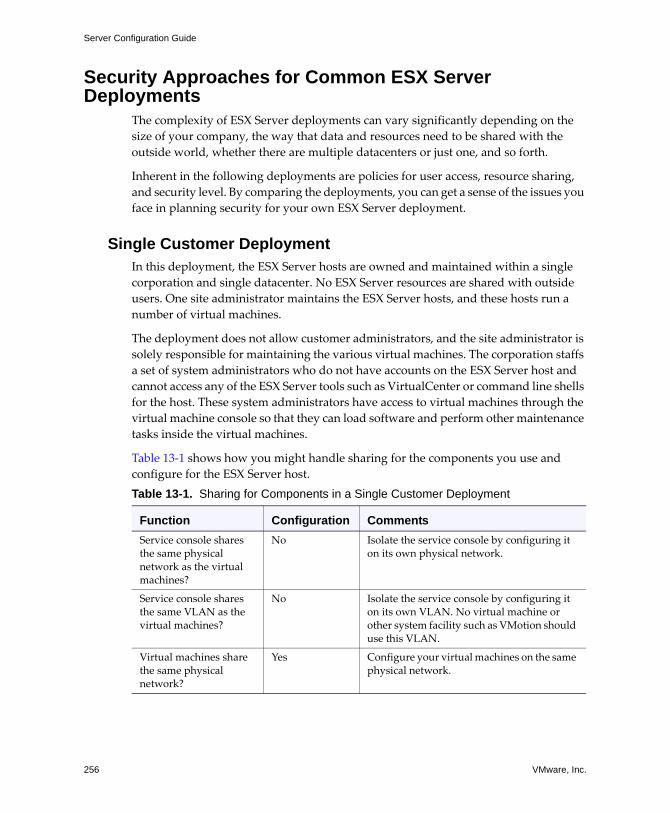
Server Configuration Guide
256 VMware, Inc.
Security Approaches for Common ESX Server Deployments
The complexity of ESX Server deployments can vary significantly depending on the size of your company, the way that data and resources need to be shared with the outside world, whether there are multiple datacenters or just one, and so forth.
Inherent in the following deployments are policies for user access, resource sharing, and security level. By comparing the deployments, you can get a sense of the issues you face in planning security for your own ESX Server deployment.
Single Customer DeploymentIn this deployment, the ESX Server hosts are owned and maintained within a single corporation and single datacenter. No ESX Server resources are shared with outside users. One site administrator maintains the ESX Server hosts, and these hosts run a number of virtual machines.
The deployment does not allow customer administrators, and the site administrator is solely responsible for maintaining the various virtual machines. The corporation staffs a set of system administrators who do not have accounts on the ESX Server host and cannot access any of the ESX Server tools such as VirtualCenter or command line shells for the host. These system administrators have access to virtual machines through the virtual machine console so that they can load software and perform other maintenance tasks inside the virtual machines.
Table 13‐1 shows how you might handle sharing for the components you use and configure for the ESX Server host.Table 13-1. Sharing for Components in a Single Customer Deployment
Function Configuration CommentsService console shares the same physical network as the virtual machines?
No Isolate the service console by configuring it on its own physical network.
Service console shares the same VLAN as the virtual machines?
No Isolate the service console by configuring it on its own VLAN. No virtual machine or other system facility such as VMotion should use this VLAN.
Virtual machines share the same physical network?
Yes Configure your virtual machines on the same physical network.
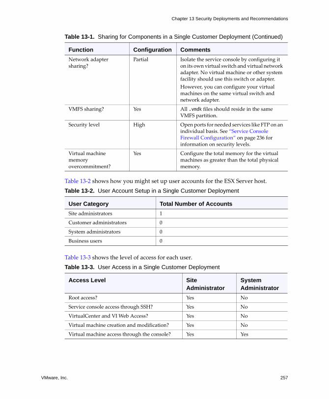
VMware, Inc. 257
Chapter 13 Security Deployments and Recommendations
Table 13‐2 shows how you might set up user accounts for the ESX Server host.
Table 13‐3 shows the level of access for each user.
Network adapter sharing?
Partial Isolate the service console by configuring it on its own virtual switch and virtual network adapter. No virtual machine or other system facility should use this switch or adapter. However, you can configure your virtual machines on the same virtual switch and network adapter.
VMFS sharing? Yes All .vmdk files should reside in the same VMFS partition.
Security level High Open ports for needed services like FTP on an individual basis. See �Service Console Firewall Configuration� on page 236 for information on security levels.
Virtual machine memory overcommitment?
Yes Configure the total memory for the virtual machines as greater than the total physical memory.
Table 13-2. User Account Setup in a Single Customer Deployment
User Category Total Number of AccountsSite administrators 1
Customer administrators 0
System administrators 0
Business users 0
Table 13-3. User Access in a Single Customer Deployment
Access Level Site Administrator
System Administrator
Root access? Yes No
Service console access through SSH? Yes No
VirtualCenter and VI Web Access? Yes No
Virtual machine creation and modification? Yes No
Virtual machine access through the console? Yes Yes
Table 13-1. Sharing for Components in a Single Customer Deployment (Continued)
Function Configuration Comments
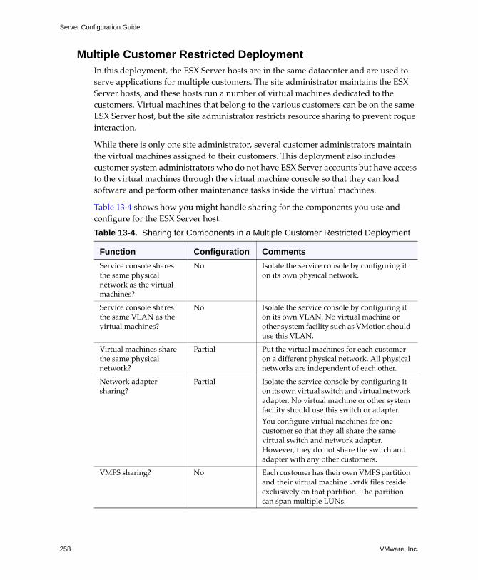
Server Configuration Guide
258 VMware, Inc.
Multiple Customer Restricted Deployment In this deployment, the ESX Server hosts are in the same datacenter and are used to serve applications for multiple customers. The site administrator maintains the ESX Server hosts, and these hosts run a number of virtual machines dedicated to the customers. Virtual machines that belong to the various customers can be on the same ESX Server host, but the site administrator restricts resource sharing to prevent rogue interaction.
While there is only one site administrator, several customer administrators maintain the virtual machines assigned to their customers. This deployment also includes customer system administrators who do not have ESX Server accounts but have access to the virtual machines through the virtual machine console so that they can load software and perform other maintenance tasks inside the virtual machines.
Table 13‐4 shows how you might handle sharing for the components you use and configure for the ESX Server host.Table 13-4. Sharing for Components in a Multiple Customer Restricted Deployment
Function Configuration CommentsService console shares the same physical network as the virtual machines?
No Isolate the service console by configuring it on its own physical network.
Service console shares the same VLAN as the virtual machines?
No Isolate the service console by configuring it on its own VLAN. No virtual machine or other system facility such as VMotion should use this VLAN.
Virtual machines share the same physical network?
Partial Put the virtual machines for each customer on a different physical network. All physical networks are independent of each other.
Network adapter sharing?
Partial Isolate the service console by configuring it on its own virtual switch and virtual network adapter. No virtual machine or other system facility should use this switch or adapter. You configure virtual machines for one customer so that they all share the same virtual switch and network adapter. However, they do not share the switch and adapter with any other customers.
VMFS sharing? No Each customer has their own VMFS partition and their virtual machine .vmdk files reside exclusively on that partition. The partition can span multiple LUNs.
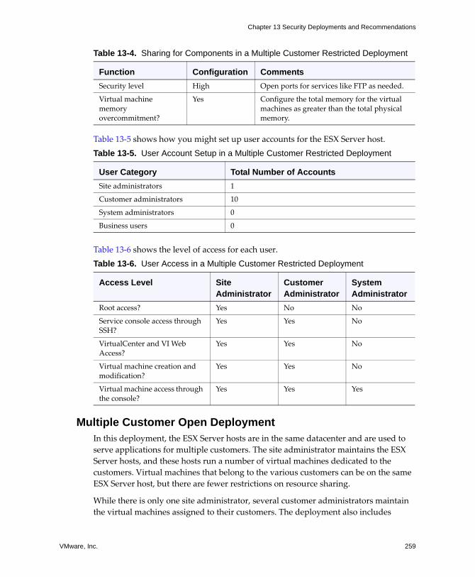
VMware, Inc. 259
Chapter 13 Security Deployments and Recommendations
Table 13‐5 shows how you might set up user accounts for the ESX Server host.
Table 13‐6 shows the level of access for each user.
Multiple Customer Open Deployment In this deployment, the ESX Server hosts are in the same datacenter and are used to serve applications for multiple customers. The site administrator maintains the ESX Server hosts, and these hosts run a number of virtual machines dedicated to the customers. Virtual machines that belong to the various customers can be on the same ESX Server host, but there are fewer restrictions on resource sharing.
While there is only one site administrator, several customer administrators maintain the virtual machines assigned to their customers. The deployment also includes
Security level High Open ports for services like FTP as needed.
Virtual machine memory overcommitment?
Yes Configure the total memory for the virtual machines as greater than the total physical memory.
Table 13-5. User Account Setup in a Multiple Customer Restricted Deployment
User Category Total Number of AccountsSite administrators 1
Customer administrators 10
System administrators 0
Business users 0
Table 13-6. User Access in a Multiple Customer Restricted Deployment
Access Level Site Administrator
Customer Administrator
System Administrator
Root access? Yes No No
Service console access through SSH?
Yes Yes No
VirtualCenter and VI Web Access?
Yes Yes No
Virtual machine creation and modification?
Yes Yes No
Virtual machine access through the console?
Yes Yes Yes
Table 13-4. Sharing for Components in a Multiple Customer Restricted Deployment
Function Configuration Comments
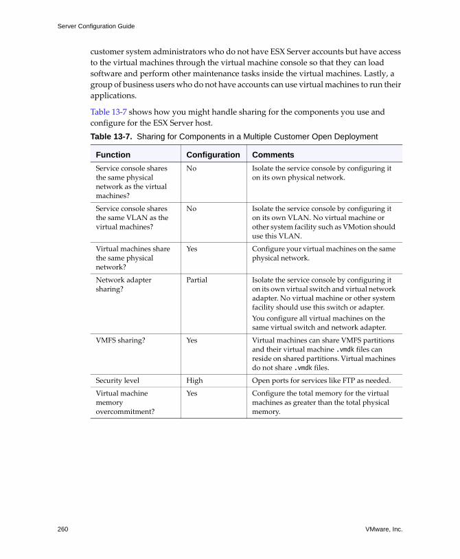
Server Configuration Guide
260 VMware, Inc.
customer system administrators who do not have ESX Server accounts but have access to the virtual machines through the virtual machine console so that they can load software and perform other maintenance tasks inside the virtual machines. Lastly, a group of business users who do not have accounts can use virtual machines to run their applications.
Table 13‐7 shows how you might handle sharing for the components you use and configure for the ESX Server host.Table 13-7. Sharing for Components in a Multiple Customer Open Deployment
Function Configuration CommentsService console shares the same physical network as the virtual machines?
No Isolate the service console by configuring it on its own physical network.
Service console shares the same VLAN as the virtual machines?
No Isolate the service console by configuring it on its own VLAN. No virtual machine or other system facility such as VMotion should use this VLAN.
Virtual machines share the same physical network?
Yes Configure your virtual machines on the same physical network.
Network adapter sharing?
Partial Isolate the service console by configuring it on its own virtual switch and virtual network adapter. No virtual machine or other system facility should use this switch or adapter. You configure all virtual machines on the same virtual switch and network adapter.
VMFS sharing? Yes Virtual machines can share VMFS partitions and their virtual machine .vmdk files can reside on shared partitions. Virtual machines do not share .vmdk files.
Security level High Open ports for services like FTP as needed.
Virtual machine memory overcommitment?
Yes Configure the total memory for the virtual machines as greater than the total physical memory.
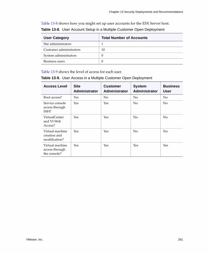
VMware, Inc. 261
Chapter 13 Security Deployments and Recommendations
Table 13‐8 shows how you might set up user accounts for the ESX Server host.
Table 13‐9 shows the level of access for each user.
Table 13-8. User Account Setup in a Multiple Customer Open Deployment
User Category Total Number of AccountsSite administrators 1
Customer administrators 10
System administrators 0
Business users 0
Table 13-9. User Access in a Multiple Customer Open Deployment
Access Level Site Administrator
Customer Administrator
System Administrator
Business User
Root access? Yes No No No
Service console access through SSH?
Yes Yes No No
VirtualCenter and VI Web Access?
Yes Yes No No
Virtual machine creation and modification?
Yes Yes No No
Virtual machine access through the console?
Yes Yes Yes Yes
Server Configuration Guide
262 VMware, Inc.
Virtual Machine RecommendationsConsider the following safety precautions when evaluating virtual machine security and administering virtual machines.
Installing Antivirus SoftwareBecause each virtual machine hosts a standard operating system, you should consider protecting it from viruses by installing antivirus software. Depending on how you are using the virtual machine, you might also want to install a software firewall.
NOTE Software firewalls and antivirus software can be virtualization‐intensive. If you are confident that your virtual machines are in a fully trusted environment, you can balance the need for these two security measures against virtual machine performance.
Disabling Copy and Paste Operations Between the Guest Operating System and Remote Console
When VMware Tools runs on a virtual machine, you can copy and paste between the guest operating system and remote console. As soon as the console window gains focus, non‐privileged users and processes running in the virtual machine can access the clipboard for the virtual machine console. If a user copies sensitive information to the clipboard before using the console, the user�perhaps unknowingly�exposes sensitive data to the virtual machine.
To prevent this problem, consider disabling copy and paste operations for the guest operating system.
To disable copy and paste operations between the guest operating system and remote console
1 Log on to the VI Client and select the virtual machine from the inventory panel.
The configuration page for this virtual machine appears with the Summary tab displayed.
2 Click Edit Settings.
3 Click Options > Advanced > Configuration Parameters to open the Configuration Parameters dialog box.
4 Click the Add button.
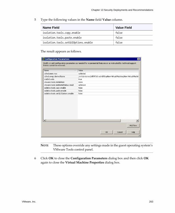
VMware, Inc. 263
Chapter 13 Security Deployments and Recommendations
5 Type the following values in the Name field Value column.
The result appears as follows.
NOTE These options override any settings made in the guest operating system�s VMware Tools control panel.
6 Click OK to close the Configuration Parameters dialog box and then click OK again to close the Virtual Machine Properties dialog box.
Name Field Value Fieldisolation.tools.copy.enable false
isolation.tools.paste.enable false
isolation.tools.setGUIOptions.enable false
Server Configuration Guide
264 VMware, Inc.
Removing Unnecessary Hardware DevicesNonprivileged users and processes within virtual machines can connect or disconnect hardware devices, such as network adapters and CD‐ROM drives. Attackers can use this capability to breach virtual machine security in several ways. For example, by default, an attacker with access to a virtual machine can:
! Connect a disconnected CD‐ROM drive and access sensitive information on the media left in the drive.
! Disconnect a network adapter to isolate the virtual machine from its network, resulting in a denial of service.
As a general security precaution, use commands on the VI Client Configuration tab to remove any unneeded or unused hardware devices. While this measure tightens virtual machine security, it isn�t a good solution in situations where you might need to bring a currently unused device back into service at a later time.
If you don�t want to permanently remove a device, you can prevent a virtual machine user or process from connecting or disconnecting the device from within the guest operating system.
To prevent a virtual machine user or process from disconnecting devices
1 Log on to the VI Client and select the virtual machine from the inventory panel.
The configuration page for this virtual machine appears with the Summary tab displayed.
2 Click Edit Settings.
The Virtual Machine Properties dialog box appears.
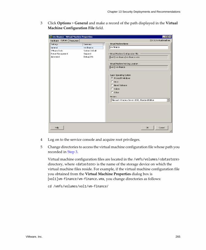
VMware, Inc. 265
Chapter 13 Security Deployments and Recommendations
3 Click Options > General and make a record of the path displayed in the Virtual Machine Configuration File field.
4 Log on to the service console and acquire root privileges.
5 Change directories to access the virtual machine configuration file whose path you recorded in Step 3.
Virtual machine configuration files are located in the /vmfs/volumes/<datastore> directory, where <datastore> is the name of the storage device on which the virtual machine files reside. For example, if the virtual machine configuration file you obtained from the Virtual Machine Properties dialog box is [vol1]vm-finance/vm-finance.vmx, you change directories as follows:
cd /vmfs/volumes/vol1/vm-finance/
Server Configuration Guide
266 VMware, Inc.
6 Use nano or another text editor to add the following line to the .vmx file.
<device_name>.allowGuestConnectionControl = “false”
Where <device_name> is the name of the device you want to protect, for example, ethernet1.
NOTE By default, Ethernet 0 is configured to disallow device disconnection. The only reason you might need to change this is if a prior administrator set the <device_name>.allowGuestConnectionControl to true.
7 Save your changes and close the file.
8 Return to the VI Client and power off and power on the virtual machine. To do so, right‐click the virtual machine in the inventory panel and click Power Off followed by Power On.
Preventing the Guest Operating System Processes from Flooding the ESX Server Host
The guest operating system processes send informational messages to the ESX Server host through VMware Tools. These messages, known as setinfo messages, typically contain name‐value pairs that define virtual machine characteristics or identifiers that the host stores�for example, ipaddress=10.17.87.224.
A setinfo message has no predefined format, and it can be any length. Therefore, the amount of data passed to the host this way is unlimited. An unrestricted data flow provides an opportunity for an attacker to stage a DOS attack by writing software that mimics VMware Tools and flooding the host with packets, thus consuming resources needed by the virtual machines.
To prevent this problem, consider limiting the ability of VMware Tools to arbitrarily send setinfo messages to the ESX Server host.
NOTE VMware Tools also sends other types of messages, but these have predefined formats and, therefore, are not good vehicles for DOS attacks.
To prevent the guest operating system processes from sending arbitrary messages to the host
1 Log on to the VI Client and select the virtual machine from the inventory panel.
The configuration page for this virtual machine appears with the Summary tab displayed.
2 Click Edit Settings.

VMware, Inc. 267
Chapter 13 Security Deployments and Recommendations
3 Click Options > Advanced > Configuration Parameters to open the Configuration Parameters dialog box.
4 Click the Add button and type the following:
! Name field � isolation.tools.setinfo.disable
! Value field � true
The result appears as follows.
5 Click OK to close the Configuration Parameters dialog box and then click OK again to close the Virtual Machine Properties dialog box.
Disabling Logging for the Guest Operating SystemVirtual machines can write troubleshooting information into a virtual machine log file stored on the VMFS volume. Virtual machine users and processes can abuse logging either on purpose or inadvertently so that large amounts of data flood the log file. Over time, the log file can consume enough of the service console�s file system space to cause a denial of service.
To prevent this problem, consider disabling logging for virtual machine guest operating systems. In making this decision, be aware that you might not be able to
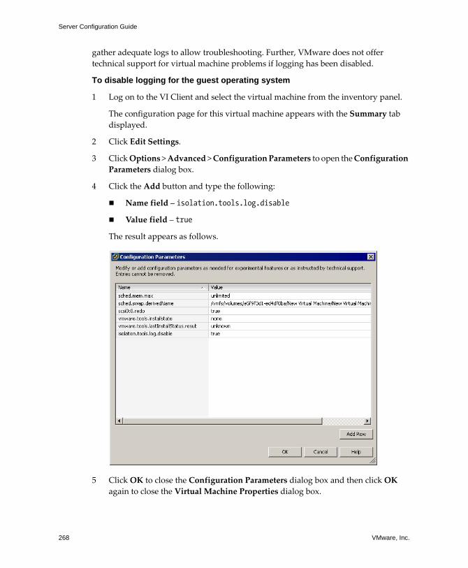
Server Configuration Guide
268 VMware, Inc.
gather adequate logs to allow troubleshooting. Further, VMware does not offer technical support for virtual machine problems if logging has been disabled.
To disable logging for the guest operating system
1 Log on to the VI Client and select the virtual machine from the inventory panel.
The configuration page for this virtual machine appears with the Summary tab displayed.
2 Click Edit Settings.
3 Click Options > Advanced > Configuration Parameters to open the Configuration Parameters dialog box.
4 Click the Add button and type the following:
! Name field � isolation.tools.log.disable
! Value field � true
The result appears as follows.
5 Click OK to close the Configuration Parameters dialog box and then click OK again to close the Virtual Machine Properties dialog box.
VMware, Inc. 269
APPENDIX A ESX Technical Support Commands
This appendix lists the service console commands used to configure ESX Server. Most of these commands are reserved for Technical Support use and are included for your reference only. In a few cases, however, these commands provide the only means of performing a configuration task for the ESX Server host. Also, if you lose your connection to the host, executing certain of these commands through the command‐line interface may be your only recourse�for example, if networking becomes nonfunctional and VI Client access is therefore unavailable.
NOTE If you use the commands in this appendix, you must execute the service mgmt-vmware restart command to restart the vmware-hostd process and alert the VI Client and other management tools that the configuration has changed. In general, avoid executing the commands in this appendix if the host is currently under the VI Client or VirtualCenter Server management.
The VI Client graphical user interface provides the preferred means of performing the configuration tasks described in this appendix. You can use this appendix to learn which VI Client commands to use in place of the service console commands. This appendix provides a summary of the actions you take in VI Client but doesn�t give complete instructions. For details on using commands and performing configuration tasks through VI Client, see the online help.
You can find additional information on a number of ESX commands by logging on to the service console and using the man <esxcfg_command_name> command to display man pages.
Table A‐1 lists the Technical Support commands provided for ESX Server, summarizes the purpose of each command, and provides a VI Client alternative. You can perform most of the VI Client actions listed in the table only after you have selected an ESX Server host from the inventory panel and clicked the Configuration tab. These actions are preliminary to any procedure discussed below unless otherwise stated.
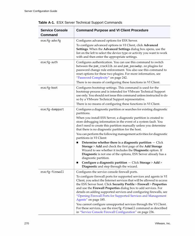
Server Configuration Guide
270 VMware, Inc.
Table A-1. ESX Server Technical Support Commands
Service Console Command
Command Purpose and VI Client Procedure
esxcfg-advcfg Configures advanced options for ESX Server. To configure advanced options in VI Client, click Advanced Settings. When the Advanced Settings dialog box opens, use the list on the left to select the device type or activity you want to work with and then enter the appropriate settings.
esxcfg-auth Configures authentication. You can use this command to switch between the pam_cracklib.so and pam_passwdqc.so plugins for password change rule enforcement. You also use this command to reset options for these two plugins. For more information, see �Password Complexity� on page 242.There is no means of configuring these functions in VI Client.
esxcfg-boot Configures bootstrap settings. This command is used for the bootstrap process and is intended for VMware Technical Support use only. You should not issue this command unless instructed to do so by a VMware Technical Support representative.There is no means of configuring these functions in VI Client.
esxcfg-dumppart Configures a diagnostic partition or searches for existing diagnostic partitions.When you install ESX Server, a diagnostic partition is created to store debugging information in the event of a system fault. You don�t need to create this partition manually unless you determine that there is no diagnostic partition for the host.You can perform the following management activities for diagnostic partitions in VI Client:! Determine whether there is a diagnostic partition � Click
Storage > Add and check the first page of the Add Storage Wizard to see whether it includes the Diagnostic option. If Diagnostic is not one of the options, ESX Server already has a diagnostic partition.
! Configure a diagnostic partition � Click Storage > Add > Diagnostic and step through the wizard.
esxcfg-firewall Configures the service console firewall ports.To configure firewall ports for supported services and agents in VI Client, you select the Internet services that will be allowed to access the ESX Server host. Click Security Profile > Firewall > Properties and use the Firewall Properties dialog box to add services. For details on adding supported services and configuring firewalls, see �Opening Firewall Ports for Supported Services and Management Agents� on page 185.You cannot configure unsupported services through the VI Client. For these services, use the esxcfg-firewall command as described in �Service Console Firewall Configuration� on page 236.
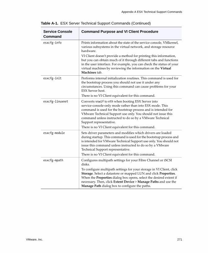
VMware, Inc. 271
Appendix A ESX Technical Support Commands
esxcfg-info Prints information about the state of the service console, VMkernel, various subsystems in the virtual network, and storage resource hardware.VI Client doesn�t provide a method for printing this information, but you can obtain much of it through different tabs and functions in the user interface. For example, you can check the status of your virtual machines by reviewing the information on the Virtual Machines tab.
esxcfg-init Performs internal initialization routines. This command is used for the bootstrap process you should not use it under any circumstances. Using this command can cause problems for your ESX Server host.There is no VI Client equivalent for this command.
esxcfg-linuxnet Converts vswif to eth when booting ESX Server into service‐console‐only mode rather than into ESX mode. This command is used for the bootstrap process and is intended for VMware Technical Support use only. You should not issue this command unless instructed to do so by a VMware Technical Support representative.There is no VI Client equivalent for this command.
esxcfg-module Sets driver parameters and modifies which drivers are loaded during startup. This command is used for the bootstrap process and is intended for VMware Technical Support use only. You should not issue this command unless instructed to do so by a VMware Technical Support representative.There is no VI Client equivalent for this command.
esxcfg-mpath Configures multipath settings for your Fibre Channel or iSCSI disks.To configure multipath settings for your storage in VI Client, click Storage. Select a datastore or mapped LUN and click Properties. When the Properties dialog box opens, select the desired extent if necessary. Then, click Extent Device > Manage Paths and use the Manage Path dialog box to configure the paths.
Table A-1. ESX Server Technical Support Commands (Continued)
Service Console Command
Command Purpose and VI Client Procedure
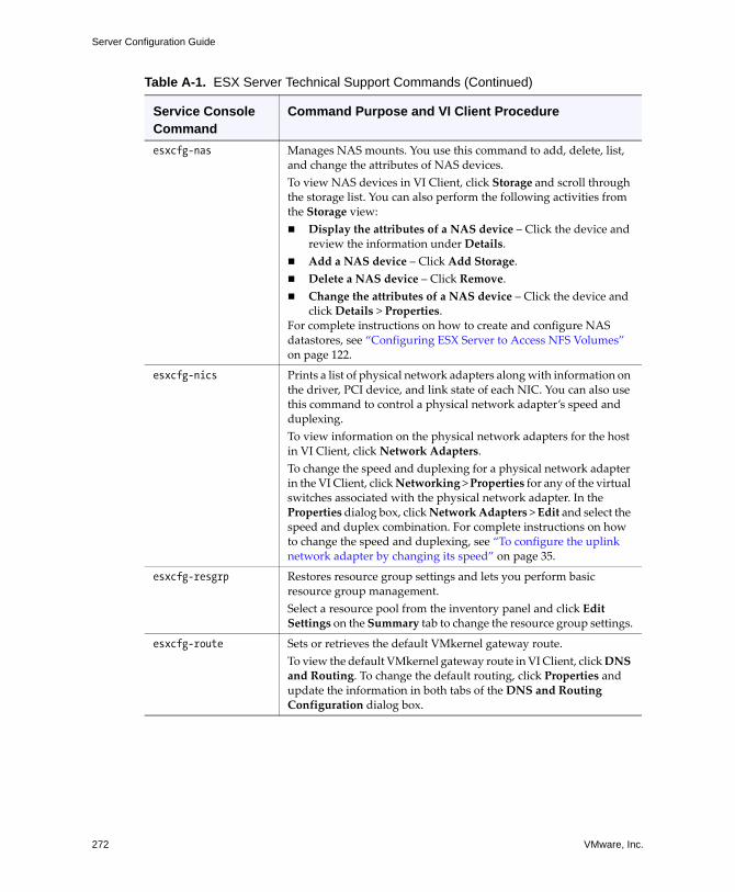
Server Configuration Guide
272 VMware, Inc.
esxcfg-nas Manages NAS mounts. You use this command to add, delete, list, and change the attributes of NAS devices.To view NAS devices in VI Client, click Storage and scroll through the storage list. You can also perform the following activities from the Storage view: ! Display the attributes of a NAS device � Click the device and
review the information under Details. ! Add a NAS device � Click Add Storage.! Delete a NAS device � Click Remove.! Change the attributes of a NAS device � Click the device and
click Details > Properties.For complete instructions on how to create and configure NAS datastores, see �Configuring ESX Server to Access NFS Volumes� on page 122.
esxcfg-nics Prints a list of physical network adapters along with information on the driver, PCI device, and link state of each NIC. You can also use this command to control a physical network adapter�s speed and duplexing.To view information on the physical network adapters for the host in VI Client, click Network Adapters. To change the speed and duplexing for a physical network adapter in the VI Client, click Networking > Properties for any of the virtual switches associated with the physical network adapter. In the Properties dialog box, click Network Adapters > Edit and select the speed and duplex combination. For complete instructions on how to change the speed and duplexing, see �To configure the uplink network adapter by changing its speed� on page 35.
esxcfg-resgrp Restores resource group settings and lets you perform basic resource group management. Select a resource pool from the inventory panel and click Edit Settings on the Summary tab to change the resource group settings.
esxcfg-route Sets or retrieves the default VMkernel gateway route.To view the default VMkernel gateway route in VI Client, click DNS and Routing. To change the default routing, click Properties and update the information in both tabs of the DNS and Routing Configuration dialog box.
Table A-1. ESX Server Technical Support Commands (Continued)
Service Console Command
Command Purpose and VI Client Procedure
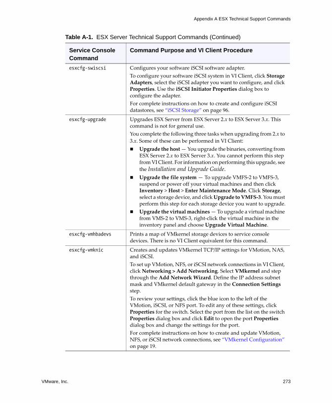
VMware, Inc. 273
Appendix A ESX Technical Support Commands
esxcfg-swiscsi Configures your software iSCSI software adapter.To configure your software iSCSI system in VI Client, click Storage Adapters, select the iSCSI adapter you want to configure, and click Properties. Use the iSCSI Initiator Properties dialog box to configure the adapter.For complete instructions on how to create and configure iSCSI datastores, see �iSCSI Storage� on page 96.
esxcfg-upgrade Upgrades ESX Server from ESX Server 2.x to ESX Server 3.x. This command is not for general use.You complete the following three tasks when upgrading from 2.x to 3.x. Some of these can be performed in VI Client:! Upgrade the host � You upgrade the binaries, converting from
ESX Server 2.x to ESX Server 3.x. You cannot perform this step from VI Client. For information on performing this upgrade, see the Installation and Upgrade Guide.
! Upgrade the file system � To upgrade VMFS‐2 to VMFS‐3, suspend or power off your virtual machines and then click Inventory > Host > Enter Maintenance Mode. Click Storage, select a storage device, and click Upgrade to VMFS‐3. You must perform this step for each storage device you want to upgrade.
! Upgrade the virtual machines � To upgrade a virtual machine from VMS‐2 to VMS‐3, right‐click the virtual machine in the inventory panel and choose Upgrade Virtual Machine.
esxcfg-vmhbadevs Prints a map of VMkernel storage devices to service console devices. There is no VI Client equivalent for this command.
esxcfg-vmknic Creates and updates VMkernel TCP/IP settings for VMotion, NAS, and iSCSI.To set up VMotion, NFS, or iSCSI network connections in VI Client, click Networking > Add Networking. Select VMkernel and step through the Add Network Wizard. Define the IP address subnet mask and VMkernel default gateway in the Connection Settings step. To review your settings, click the blue icon to the left of the VMotion, iSCSI, or NFS port. To edit any of these settings, click Properties for the switch. Select the port from the list on the switch Properties dialog box and click Edit to open the port Properties dialog box and change the settings for the port.For complete instructions on how to create and update VMotion, NFS, or iSCSI network connections, see �VMkernel Configuration� on page 19.
Table A-1. ESX Server Technical Support Commands (Continued)
Service Console Command
Command Purpose and VI Client Procedure
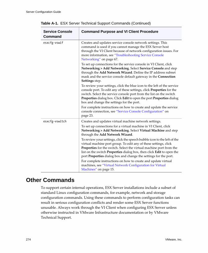
Server Configuration Guide
274 VMware, Inc.
Other CommandsTo support certain internal operations, ESX Server installations include a subset of standard Linux configuration commands, for example, network and storage configuration commands. Using these commands to perform configuration tasks can result in serious configuration conflicts and render some ESX Server functions unusable. Always work through the VI Client when configuring ESX Server unless otherwise instructed in VMware Infrastructure documentation or by VMware Technical Support.
esxcfg-vswif Creates and updates service console network settings. This command is used if you cannot manage the ESX Server host through the VI Client because of network configuration issues. For more information, see �Troubleshooting Service Console Networking� on page 67.To set up connections for the service console in VI Client, click Networking > Add Networking. Select Service Console and step through the Add Network Wizard. Define the IP address subnet mask and the service console default gateway in the Connection Settings step. To review your settings, click the blue icon to the left of the service console port. To edit any of these settings, click Properties for the switch. Select the service console port from the list on the switch Properties dialog box. Click Edit to open the port Properties dialog box and change the settings for the port.For complete instructions on how to create and update the service console connection, see �Service Console Configuration� on page 23.
esxcfg-vswitch Creates and updates virtual machine network settings.To set up connections for a virtual machine in VI Client, click Networking > Add Networking. Select Virtual Machine and step through the Add Network Wizard. To review your settings, click the speech bubble icon to the left of the virtual machine port group. To edit any of these settings, click Properties for the switch. Select the virtual machine port from the list on the switch Properties dialog box, then click Edit to open the port Properties dialog box and change the settings for the port.For complete instructions on how to create and update virtual machines, see �Virtual Network Configuration for Virtual Machines� on page 15.
Table A-1. ESX Server Technical Support Commands (Continued)
Service Console Command
Command Purpose and VI Client Procedure
VMware, Inc. 275
APPENDIX B Using vmkfstools
You use the vmkfstools program to create and manipulate virtual disks, file systems, logical volumes, and physical storage devices on the VMware ESX Server. Using vmkfstools, you can create and manage VMware File System (VMFS) on a physical partition of a disk. You can also use this program to manipulate files, such as virtual disks, stored on VMFS‐2, VMFS‐3, and NFS.
Most vmkfstools operations can also be performed through the VI Client. For information on using the VI Client to work with storage, see �Configuring Storage� on page 89.
This appendix covers the following sections:
! �vmkfstools Command Syntax� on page 276! �vmkfstools Options� on page 277! �Examples Using vmkfstools� on page 289
Server Configuration Guide
276 VMware, Inc.
vmkfstools Command SyntaxGenerally, you don�t need to log in as the root user to run the vmkfstools commands. However, some commands, such as the file system commands, might require the root login.
Use the following arguments with the vmkfstools command:
! <options> are one or more command line options and associated arguments you use to specify the activity that you want vmkfstools to perform � for example, choosing the disk format when creating a new virtual disk.
After entering the option, specify a file or VMFS file system, on which you perform the operation, by entering a relative or absolute file path name in the /vmfs hierarchy.
! <partition> specifies disk partitions. This argument uses a vmhbaA:T:L:P format, where A, T, L, and P are integers representing adapter, target, LUN, and partition number respectively. The partition digit must be greater than zero and should correspond to a valid VMFS partition of type fb.
For example, vmhba0:2:3:1 refers to the first partition on LUN 3, target 2, HBA 0.
! <device> specifies devices or logical volumes. This argument uses a path name in the ESX Server device file system. The path name begins with /vmfs/devices, which is the mount point of the device file system.
Use the following formats when specifying different types of devices:
! /vmfs/devices/disks for local or SAN‐based disks.
! /vmfs/devices/lvm for ESX Server logical volumes.
! /vmfs/devices/generic for generic SCSI devices, such as tape drives.
VMware, Inc. 277
Chapter B Using vmkfstools
! <path> specifies a VMFS file system or file. This argument is an absolute or relative path that names a directory symbolic link, raw device mapping, or a file under /vmfs.
! To specify a VMFS file system, use this format:
/vmfs/volumes/<file_system_UUID> or /vmfs/volumes/<file_system_label>
! To specify a VMFS file, use this format:
/vmfs/volumes/<file system label|file system UUID>/[dir]/myDisk.vmdk
You don�t need to enter the entire path if the current working directory is the parent directory of myDisk.vmdk.
For example,
/vmfs/volumes/datastore1/rh9.vmdk
-v SuboptionThe -v suboption indicates the verbosity level of the command output. The format for this suboption is as follows:
-v --verbose <number>
You specify the <number> value as an integer from 1 through 10.
You can specify the -v suboption with any vmkfstools option. If the output of the option isn�t suitable for use with the -v suboption, vmkfstools ignores the -v part of the command line.
NOTE Because you can include the -v suboption in any vmkfstools command line, the suboption is not specifically covered in any of the option descriptions.
vmkfstools OptionsThis section includes a list of all the options used with the vmkfstools command. Some of the tasks in this section include options suggested for advanced users only.
The long and short (single letter) forms of options are equivalent. For example, the following commands are identical:
vmkfstools --createfs vmfs3 --blocksize 2m vmhba1:3:0:1vmkfstools -C vmfs3 -b 2m vmhba1:3:0:1
Server Configuration Guide
278 VMware, Inc.
File System OptionsFile system options are tasks that you can perform when setting up a VMFS file system. These options do not apply to NFS.
You can perform many of these tasks through the VI Client.
Creating a VMFS File System-C --createfs vmfs3
-b --blocksize <block_size>kK|mM -S --setfsname <fsName>
This option creates a VMFS‐3 file system on the specified SCSI partition, such as vmhba1:0:0:1. The partition becomes the file systemʹs head partition.
NOTE VMFS‐2 file systems are read‐only on any ESX Server 3. You cannot create or modify VMFS‐2 file systems but are able to read files stored on VMFS‐2 file systems. VMFS‐3 file systems are not accessible from ESX 2.x hosts.
CAUTION Be aware that you can have only one VMFS volume for a LUN.
You can specify the following suboptions with the -C option:
! -b --blocksize � Define the block size for the VMFS‐3 file system. The default file block size is 1MB. The <block_size> value you specify must be either 1MB, 2MB, 4MB, or 8MB. When entering a size, indicate the unit type by adding a suffix of m or M. The unit type is not case sensitive�vmkfstools interprets either m or M to mean megabytes.
! -S --setfsname � Define the volume label of a VMFS volume for the VMFS‐3 file system you are creating. Use this suboption only in conjunction with the -C option.The label you specify can be up to 128 characters long and cannot contain any leading or trailing blank spaces.
After you define a volume label, you can use it whenever specifying the VMFS volume for the vmkfstools command. You can also use the VMFS volume when referencing the volume in virtual machine configuration files. The volume name appears in listings generated for the Linux ls -l command and as a symbolic link to the VMFS volume under the /vmfs/volumes directory.
VMware, Inc. 279
Chapter B Using vmkfstools
To change the VMFS volume label, use the Linux ln -sf command. Use the following as an example:
ln -sf /vmfs/volumes/<UUID> /vmfs/volumes/<fsName>
<fsName> is the new volume label you want to use for the <UUID> VMFS.
Examplevmkfstools -C vmfs3 -b 1m -S myVMFS vmhba1:3:0:1
This example illustrates creating a new VMFS‐3 file system named myvmfs on the first partition of target 3, LUN 0 of vmhba adapter 1. The file block size is 1MB.
Extending an Existing VMFS-3 Volume-Z --extendfs <extention-device> <existing-VMFS-volume>
This option adds another extent to a previously created VMFS volume <existing-VMFS-volume>. Each time you use this option, you extend a VMFS‐3 volume with a new extent so that the volume spans multiple partitions. At most, a logical VMFS‐3 volume can have 32 physical extents.
CAUTION By running this option, you lose all data that previously existed on the SCSI device you specified in <extension-device>.
Examplevmkfstools -Z vmhba0:1:2:4 vmhba1:3:0:1
This example illustrates extending the logical file system by allowing it to span to a new partition. The extended file system spans two partitions�vmhba1:3:0:1 and vmhba0:1:2:4. In this example, vmhba1:3:0:1 is the name of the head partition.
Server Configuration Guide
280 VMware, Inc.
Listing Attributes of a VMFS Volume -P --queryfs
-h --human-readable
This option lists the attributes of the specified VMFS volume when used on any file or directory that resides on the VMFS volume. The listed attributes include the VMFS version number (VMFS‐2 or VMFS‐3), the number of extents comprising the specified VMFS volume, the volume label if any, the UUID, and a listing of the device names where each extent comprising the VMFS volume resides.
NOTE If any device backing VMFS file system goes offline, the number of extents and available space change accordingly.
You can specify the -h suboption with the -P option. If you do so, vmkfstools lists the capacity of the volume in a more readable form�for example, 5k, 12.1M, or 2.1G.
Upgrading a VMFS-2 to VMFS-3 You upgrade the VMFS‐2 file system to VMFS‐3 by using the following options:
! -T --tovmfs3 -x --upgradetype [zeroedthick|eagerzeroedthick|thin]
This option converts the VMFS‐2 file system VMFS‐3 preserving all files on the file system. Before using the -T option, unload the vmfs2 and vmfs3 drivers and load the auxiliary file system driver, fsaux, with a module option fsauxFunction=upgrade.
Use the -x --upgradetype [zeroedthick|eagerzeroedthick|thin] suboption with the -T option:
! -x zeroedthick (default) � Retains the properties of VMFS‐2 thick files. With the zeroedthick file format, disk space is allocated to the files for future use and the unused data blocks are not zeroed out.
! -x eagerzeroedthick � Zeroes out unused data blocks in thick files during conversion. If you use this suboption, the upgrade process might take much longer than with the other options.
! -x thin � Converts the VMFS‐2 thick files into thin‐provisioned VMFS‐3 files. As opposed to thick file format, the thin‐provisioned format doesnʹt allow files to have extra space allocated for their future use, but instead provides the space on demand. During this conversion, unused blocks of the thick files are discarded.
VMware, Inc. 281
Chapter B Using vmkfstools
During conversion, the ESX Server file‐locking mechanism ensures that no other local process is accessing the VMFS volume that is being converted, while you need to make sure that no remote ESX server is accessing this volume. The conversion might take several minutes and signals the completion by returning the command line prompt.
After conversion, unload the fsaux driver and load vmfs3 and vmfs2 drivers to resume normal operations.
! -u --upgradefinish
This option completes the upgrade.
CAUTION The VMFS‐2 to VMFS‐3 conversion is a one‐way process. Once the VMFS volume is converted to VMFS‐3, you cannot revert it back to a VMFS‐2 volume.
Virtual Disk OptionsVirtual disk options are tasks that you can perform when setting up, migrating, and managing virtual disks stored in file systems VMFS‐2, VMFS‐3, and NFS. You can also perform most of these tasks through the VI Client.
Supported Disk FormatsWhen creating or cloning virtual disks, you can use the -d --diskformat suboption to specify format for your disk. Choose an appropriate format:
! zeroedthick (default) � Space required for the virtual disk is allocated during creation. Any data remaining on the physical device is not erased during creation, but will be zeroed out at a later time during virtual machine read and write operations.
! eagerzeroedthick � Space required for the virtual disk is allocated at creation time. Unlike with the zeroedthick format, the data remaining on the physical device is zeroed out during creation. Disks in this format might take much longer to create than other types of disks.
! thick � Space required for the virtual disk is allocated during creation. This type of formatting doesn�t zero out any old data that might be present on this allocated space.
! thin � Thin‐provisioned virtual disk. Unlike with the thick format, space required for the virtual disk is not allocated during creation, but is supplied, zeroed out, on demand at a later time.
Server Configuration Guide
282 VMware, Inc.
! rdm � Virtual compatibility mode raw disk mapping.
! rdmp � Physical compatibility mode (pass‐through) raw disk mapping.
! raw � Raw device.
! 2gbsparse � A sparse disk with 2GB maximum extent size. Disks in this format can be used with other VMware products.
NOTE The only disk formats that can be used for NFS are thin and 2gbsparse. By default, files and virtual disks are stored in thin format on NFS servers, with blocks allocated on demand as needed. No other options, including RDMs, are supported on NFS.
Creating a Virtual Disk -c --createvirtualdisk <size>[kK|mM|gG]
-a --adaptertype [buslogic|lsilogic] <srcfile>-d --diskformat [thin|zeroedthick|thick|eagerzeroedthick]
This option creates a virtual disk at the specified path on a VMFS volume. You need to specify the size of the virtual disk. When entering the value for <size>, you can indicate the unit type by adding a suffix of k (kilobytes), m (megabytes), or g (gigabytes). The unit type is not case sensitive�vmkfstools interprets either k or K to mean kilobytes. If you don�t specify a unit type, vmkfstools defaults to bytes.
You can specify the following suboptions with the -c option.
! -c specifies the device driver that will be used to communicate with the virtual disks. You can choose between BusLogic and LSI Logic SCSI drivers.
! -d specifies disk formats. For detailed description of the disk formats, see �Supported Disk Formats� on page 281.
Examplevmkfstools -c 2048m /vmfs/volumes/myVMFS/rh6.2.vmdk
This example illustrates creating a two‐gigabyte virtual disk file named rh6.2.vmdk on the VMFS file system named myVMFS. This file represents an empty virtual disk that can be accessed by a virtual machine.
VMware, Inc. 283
Chapter B Using vmkfstools
Initializing a Virtual Disk-w --writezeros
This option cleans the virtual disk by writing zeros over all its data. Depending on the size of your virtual disk and I/O bandwidth to the device hosting the virtual disk, completing this command might take a long time.
CAUTION When using this command, you lose any existing data on the virtual disk.
Inflating a Thin Virtual Disk-j --inflatedisk
This option converts a thin virtual disk to eagerzeroedthick preserving all existing data. Any blocks which were not allocated initially will be allocated and zeroed out.
For more information on disc formats, see �Supported Disk Formats� on page 281.
Deleting a Virtual Disk -U --deletevirtualdisk
This option deletes files associated with the virtual disk listed at the specified path on the VMFS volume.
Renaming a Virtual Disk -E --renamevirtualdisk <oldName> <newName>
This option renames a file associated with the virtual disk listed in the path specification portion of the command line. For the -E option to work, you must indicate the original file name or file path <oldName> and define the new file name or file path <newName>.
Server Configuration Guide
284 VMware, Inc.
Cloning a Virtual or Raw Disk -i --importfile <srcfile>
-d --diskformat [rdm:<device>|rdmp:<device>|raw:<device>|thin|2gbsparse]
This option creates a copy of a virtual disk or raw disk you specify.
You can use the -d suboption for the -i option. This suboption specifies the disk format for the copy you create. For detailed description of the disk formats, see �Supported Disk Formats� on page 281.
NOTE To clone the ESX Server Redo logs while preserving their hierarchy, use the cp command.
Examplevmkfstools -i /vmfs/volumes/templates/gold-master.vmdk /vmfs/volumes/myVMFS/myOS.vmdk
This example illustrates cloning the contents of a master virtual disk from the template repository to a virtual disk file named myOS.vmdk on the file system named myVMFS. You can configure a virtual machine to use this virtual disk by adding lines to the virtual machine configuration file, as in the following example:
scsi0:0.present = TRUE scsi0:0.fileName = /vmfs/volumes/myVMFS/myOS.vmdk
Migrating VMware Workstation and VMware GSX Server Virtual MachinesYou cannot use VI Client to migrate virtual machines created with VMware Workstation or VMware GSX Server into your ESX Server system. However, you can use the vmkfstools -i command to import the virtual disk into your ESX Server system and then attach this disk to a new virtual machine you create in ESX Server.
To Migrate Workstation and GSX Server Virtual Machines
1 Import a Workstation or GSX Server disk into your /vmfs/volumes/myVMFS/ directory.
2 In the VI Client, create a new virtual machine using the Custom configuration option.
3 When configuring a disk, select Use an existing virtual disk option and attach the Workstation or GSX Server disk you imported.
VMware, Inc. 285
Chapter B Using vmkfstools
Extending a Virtual Disk -X --extendvirtualdisk <newSize>[kK|mM|gG]
This option extends the size of a disk allocated to a virtual machine after the virtual machine has been created. The virtual machine that uses this disk file must be powered off when you enter this command. Also, to take advantage of the extra space, the guest operating system must be able to recognize and use the new size of the disk, for example by updating the file system on the disk.
You specify the newSize parameter in kilobytes, megabytes, or gigabytes by adding a suffix of k (kilobytes), m (megabytes), or g (gigabytes), respectively. The unit type is not case sensitive�vmkfstools interprets either k or K to mean kilobytes. If you don�t specify a unit type, vmkfstools defaults to kilobytes.
NOTE The newSize parameter defines the entire new size, not just the increment you add to the disk.
For example, to extend a 4 g virtual disk by 1 g, enter:vmkfstools -X 5g
Migrating a VMFS-2 Virtual Disk to VMFS-3-M --migratevirtualdisk
This option converts the specified virtual disk file from ESX Server 2 format to ESX Server 3 format.
Creating a Virtual Compatibility Mode Raw Device Mapping-r --createrdm <device>
This option creates a Raw Device Mapping (RDM) file on a VMFS‐3 volume and maps a raw disk to this file. After this mapping is established, you can access the raw disk as you would a normal VMFS virtual disk. The file length of the mapping is the same as the size of the raw disk it points to.
When specifying the <device> parameter, enter 0 for the partition indicating that the entire raw disk is used. Use the following format:
/vmfs/devices/disks/vmhbaA:T:L:0
See �vmkfstools Command Syntax� on page 276 for more information.
Server Configuration Guide
286 VMware, Inc.
For more details on configuring and using RDMs, see �Raw Device Mapping� on page 141.
NOTE All VMFS‐3 file‐locking mechanisms apply to raw disk mappings.
Examplevmkfstools -r /vmfs/devices/disks/vmhba1:3:0:0 foo_rdm.vmdk
This example illustrates creating an RDM file named foo_rdm.vmdk and mapping the vmhba1:3:0:0 raw disk to that file. You can configure a virtual machine to use the foo_rdm.vmdk mapping file by adding the following lines to the virtual machine configuration file:
scsi0:0.present = TRUE scsi0:0.fileName = /vmfs/volumes/myVMFS/foo_rdm.vmdk
Listing Attributes of an RDM-q --queryrdm
This option lets you list the attributes of a raw disk mapping.
When used with a rdm:<device> or raw:<device> specification, this option prints out the vmhba name of the raw disk, referenced by the <device>, that uses the mapping file. The option also prints out any existing identification information for the raw disk.
Creating a Physical Compatibility Mode Raw Device Mapping-z --createrdmpassthru <device>
This option lets you map a pass‐through raw device to a file on a VMFS volume. This mapping lets a virtual machine bypass ESX Server SCSI command filtering when accessing its virtual disk.This type of mapping is useful when the virtual machine needs to send proprietary SCSI commands, for example, when SAN‐aware software is run inside the virtual machine.
After you establish this type of mapping, you can use it to access the raw disk just as you would any other VMFS virtual disk.
When specifying the <device> parameter, enter 0 for the partition indicating that the entire raw device is used. Use the following format:
/vmfs/devices/disks/vmhbaA:T:L:0
See �vmkfstools Command Syntax� on page 276 for more information.
VMware, Inc. 287
Chapter B Using vmkfstools
Creating a Raw Device Descriptor File-Q --createrawdevice <device>
This option creates a raw device descriptor file on a VMFS file system. This option should be used only for generic SCSI devices, such as tape drives.
When entering the <device> parameter, use the following format:
/vmfs/devices/generic/vmhbaA:T:L:P
See �vmkfstools Command Syntax� on page 276 for more information.
Displaying Virtual Disk Geometry-g --geometry
This option gets information about the geometry of a virtual disk.
The output is in the form: Geometry information C/H/S , where C represents the number of cylinders, H represents the number of heads, and S represents the number of sectors.
NOTE When importing VMware Workstation virtual disks to ESX Server, you may see a disk geometry mismatch error message. A disk geometry mismatch may also be the cause of problems loading a guest operating system or running a newly created virtual machine.
Device Options Device options let you perform administrative tasks for physical storage devices you are working with. You can perform most of these tasks through the VI Client.
Scanning Adapters -s --scan <adapterName>
This option scans a specified adapter for newly added or changed devices or LUNs. The -s option is especially useful for adapters connected to storage area networks (SANs). If a new device or LUN becomes accessible through the adapter, ESX Server registers this new device for use by virtual machines. If an existing LUN is no longer available, then it is removed from use by virtual machines.
NOTE If you want to scan all adapters, use the following command:
esxcfg-rescan
You can see the results of the scan by using ls /vmfs/devices/disks.
Server Configuration Guide
288 VMware, Inc.
Examplevmkfstools -s vmhba1
This example illustrates scanning the vmhba1 adapter to determine whether any new targets or LUNs have been added. This command also determines if any targets or LUNs have been removed.
Managing SCSI Reservations of LUNs -L --lock [reserve|release|lunreset|targetreset|busreset]<device>
This option lets you reserve a SCSI LUN for exclusive use by an ESX Server host, release a reservation so that other hosts can access the LUN, and reset a reservation, forcing all reservations from the target to be released.
CAUTION Using the -L option can interrupt the operations of other servers on a storage area network (SAN). Use the -L option only when troubleshooting clustering setups.
Unless specifically advised by VMware, never use this option on a LUN hosting a VMFS volume.
You can specify the -L option in several ways:
! -L reserve � Reserves the specified LUN. After the reservation, only the server that reserved that LUN can access it. If other servers attempt to access that LUN, they will get a reservation error.
! -L release � Releases the reservation on the specified LUN. Any other server can access the LUN again.
! -L lunreset � Resets the specified LUN by clearing any reservation on the LUN and making the LUN available to all servers again. The reset does not affect any of the other LUNs on the device. If another LUN on the device is reserved, it remains reserved.
! -L targetreset � Resets the entire target. The reset clears any reservations on all the LUNs associated with that target and makes the LUNs available to all servers again.
! -L busreset � Resets all accessible targets on the bus. The reset clears any reservation on all the LUNs accessible through the bus and makes them available to all servers again.
VMware, Inc. 289
Chapter B Using vmkfstools
When entering the <device> parameter, use the following format:
/vmfs/devices/disks/vmhbaA:T:L:P
See �vmkfstools Command Syntax� on page 276 for more information.
Examples Using vmkfstoolsThis section includes examples using the vmkfstools command with the different options described previously.
Create a New VMFS-3 File System vmkfstools -C vmfs3 -b 1m -S myVMFS vmhba1:3:0:1
This example illustrates creating a new VMFS‐3 file system named myvmfs on the first partition of target 3, LUN 0 of SCSI adapter 1. The file block size is 1MB.
Add a Partition to VMFS-3 File System vmkfstools -Z vmhba0:1:2:4 vmhba1:3:0:1
This example illustrates extending the logical file system by allowing it to span to a new partition. The extended file system spans two partitions�vmhba1:3:0:1 and vmhba0:1:2:4. In this example, vmhba1:3:0:1 is the name of the head partition.
Create a New Virtual Disk vmkfstools -c 2048m /vmfs/volumes/myVMFS/myOS.vmdk
This example illustrates creating a two‐gigabyte virtual disk file named myOS.vmdk on the VMFS file system named myVMFS. This file represents an empty virtual disk that can be accessed by a virtual machine.
Clone a Virtual Diskvmkfstools -i /vmfs/volumes/templates/gold-master.vmdk /vmfs/volumes/myVMFS/myOS.vmdk
This example illustrates cloning the contents of a master virtual disk from the template repository to a virtual disk file named myOS.vmdk on the file system named myVMFS. You can configure a virtual machine to use this virtual disk by adding lines to the virtual machine configuration file, as in the following example:
scsi0:0.present = TRUE scsi0:0.fileName = /vmfs/volumes/myVMFS/myOS.vmdk
Server Configuration Guide
290 VMware, Inc.
Create a Raw Device Mappingvmkfstools -r /vmfs/devices/disks/vmhba1:3:0:0 foo_rdm.vmdk
This example illustrates creating an RDM file named foo_rdm.vmdk and maps the vmhba1:3:0:0 raw disk to that file. You can configure a virtual machine to use the foo_rdm.vmdk mapping file as you did in the previous example. See �Clone a Virtual Disk� on page 289.
Scan an Adapter for Changes vmkfstools -s vmhba1
This example illustrates scanning the vmhba1 adapter to determine whether any new targets or LUNs have been added. This command also determines if any targets or LUNs have been removed.
VMware, Inc. 291
Index
Symbols* next to path 135
Aaccessing storage 78adding
Fibre Channel storage 94groups to ESX Server hosts 220iSCSI hardware-initiated
storage 107iSCSI software-initiated
storage 116local SCSI storage 90NFS storage 122users to ESX Server hosts 216users to groups 221
Administrator role 213asterisk next to path 135authenticating
groups 210users 209
authentication daemon 206
BBlade servers
and virtual networking 62configuring a virtual machine port
group 63configuring a VMkernel port 64
Ccanonical paths 133certificates
certificate file 222configuring ESX Server
searches 224disabling SSL for VI Web Access
and SDK 223key file 222location 222
certification 171changing
password aging for ESX Server 241password aging for users and
groups 242proxy services for ESX Server 224service console password
plugin 247SSH configuration 252
checking authentication for iSCSI adapters 199
CIM and firewall ports 185closing ports in the service console
firewall 238command reference for ESX Server 269compatibility modes
physical 147virtual 147
configuringdelegate user 230ESX Server certificate
searches 224
Server Configuration Guide
292 VMware, Inc.
Fibre Channel storage 94hardware-initiated iSCSI
storage 107local SCSI storage 90multipathing for Fibre Channel
storage 136password complexity 246password reuse rules 245RDM 151software-initiated iSCSI
storage 116current multipathing state 133
DDAS firewall port for ESX Server 180datastores
adding extents 130and file systems 76configuring on NFS volumes 122creating on Fibre Channel
devices 94creating on hardware-initiated iSCSI
storage 107creating on SCSI disk 90creating on software-initiated iSCSI
storage 116managing 126removing 127renaming 129rescanning 118viewing in VI Client 79
delegate user 229–230deployments for security 256determining the firewall security level for
the service console 237DHCP 29disabling
authentication for iSCSI
adapters 201cut and paste for guest operating
systems 262logging for guest operating
systems 266, 268SSL for VI Web Access and
SDK 223disabling paths 137DNS 48dynamic discovery 98
Eenabling paths 138encryption
and enabling and disabling SSL 222for user name, passwords, and
packets 222ESX Server
adding groups 220adding users 216architecture and security
features 160authentication 206authentication for iSCSI
storage 198changing proxy services 224cipher strength for connections 248command reference 269delegate user 229deployments and security 256host to host firewall ports 184password restrictions 240security overview 160users 206virtual switch security 191VLAN security 191
ESX Server host passwordsaging 241
VMware, Inc. 293
Index
changing the plugin 247complexity 242configuring password
complexity 246configuring password reuse
rules 245new password criteria 242
esxcfg commands 269EUI identifier 98exporting ESX Server host users and
groups 216extents 130
Ffailover 43failover paths
status 134failovers
with Fibre Channel storage 132Fibre Channel storage
adding 94overview 93
file systemsmanaging 126NFS 76upgrading 127VMFS 76
firewall portsand encryption 222backup agents 236CIM 185configured with a VirtualCenter
Server 176configured without a VirtualCenter
Server 179determining the firewall security
level for the service console 237
for connecting the virtual machine console 183
for management access 180FTP 185host to host 184iSCSI software client 185license server and VirtualCenter
Server 176management 185NFS 185NIS 185opening and closing for the service
console 238opening with the VI Client 185overview 174SDK and the virtual machine
console 183security level 236service console 236setting the security level for the
service console firewall 237
SMB 185SNMP 185SSH 185supported services 185VI Client and the virtual machine
console 183VI Client and VirtualCenter
Server 176VI Client direct connection 179VI Web Access and the virtual
machine console 183VI Web Access and VirtualCenter
Server 176VI Web Access direct
connection 179Fixed path policy 136
Server Configuration Guide
294 VMware, Inc.
preferred path 138FTP and firewall ports 185
Ggroups
adding to ESX Server hosts 220authentication 210exporting a group list 216Groups table for ESX Server
hosts 215modifying on ESX Server hosts 221removing from ESX Server
hosts 221viewing group lists 215
guest operating systemsdisabling cut and paste 262disabling logging 266, 268security recommendations 262
HHTTP and HTTPS firewall port 180
IIQN identifier 98iSCSI
authenticating 198CHAP 198checking authentication 199configuring CHAP
authentication 200disabling authentication 201firewall port for ESX Server 180networking 56protecting transmitted data 202QLogic iSCSI adapters 197security 197software client and firewall
ports 185
iSCSI hardware-initiated storageadding 107overview 100
iSCSI HBAalias 103CHAP authentication 106CHAP parameters 103dynamic discovery 103static discovery 103
iSCSI networkingcreating a service console
connection 60creating a VMkernel port 56
iSCSI securing ports 202iSCSI software-initiated storage
adding 116overview 109
iSCSI storagediscovery methods 98EUI identifier 98hardware-initiated 96initiators 96IQN identifier 98name formats 98security 99software-initiated 96
isolationvirtual machine 161virtual networking layer 165virtual switches 165VLANs 165
KKnowledge base xiv
LLayer 2 security 39
VMware, Inc. 295
Index
license serverfirewall ports for 180firewall ports with VirtualCenter
Server 176load balancing 43local SCSI storage
adding 90overview 90
MMAC address
configuring 52generating 51
Manage Paths wizard 138management access
firewall ports 180modifying
groups on ESX Server hosts 221users on ESX Server hosts 218
Most Recently Used path policy 136multipathing
active paths 134canonical paths 133dead paths 134disabled paths 134failover 136for Fibre Channel storage 132managing 136standby paths 134
multipathing policysetting 136
multipathing state 133
NNAS
firewall port for ESX Server 180mounting 54
Nessus 253
networking best practices 53networks
security 188NFS
delegate users 229firewall ports 185
NFS storageadding 122overview 119
NIC teamingdefinition 8
NIS and firewall ports 185No Access role 213
Oopening ports in the service console
firewall 238
Ppam_cracklib.so plugin 242pam_passwdqc.so plugin 247password restrictions
aging 241complexity 242for the ESX Server host 240minimum length 242
path failure 132path policies
Fixed 136Most Recently Used 136
pathsdisabling 137enabling 138preferred 135, 138
permissionsand prvileges 211overview 211root user 211
Server Configuration Guide
296 VMware, Inc.
VirtualCenter administrator 211vpxuser 211
port groupconfiguring 46definition 8using 12
preferred path 135, 138preventing malicious device
disconnection 264privileges
and permissions 211proxy services
and encryption 222changing 224
Rraw device mapping
see RDM 142RDM
advantages 144and virtual disk files 151and vmkfstools 154creating 151dynamic name resolution 148overview 142physical compatibility mode 147virtual compatibility mode 147with clustering 150
Read Only role 213removing
groups from ESX Server hosts 221users from ESX Server hosts 219users from groups 221
resource guarantees and security 161resource limits and security 161roles
Administrator 213
and permissions 213default 213No Access 213Read Only 213
root logindelegate user 229permissions 211SSH 252
routing 48RPMs 253
SSCSI
vmkfstools 275SDK and firewall ports for connecting to
the virtual machine console 183
securityCHAP authentication 198cipher strength 248delegate user 229direct access users 209encryption 222ESX Server architecture 160example, DMZ in a single ESX
Server host 166, 168forged transmissions 195groups 210iSCSI storage 197MAC address changes 195overview of users, groups,
permissions, and roles 208
PAM authentication 206password restrictions for the ESX
Server host 240patches 253permissions 211
VMware, Inc. 297
Index
promiscuous mode 195recommendations for virual
machines 262roles 213scanning software 253security certificates 222service console firewall security
level 236service console security
measures 163setgid applications 249setuid applications 249SSH connections 252user authentication 206user managment 206virtual machines 161virtual network 188virtual networking layer 165VirtualCenter users 209virtualization layer 160VLAN hopping 191VLANs 188VMkernel 160VMware policy 171vmware-authd 206
service consoledirect connections 235logging on 235password restrictions 240recommendations for securing 234remote connections 235securing with VLANs and virtual
switches 191security 163setgid applications 249setuid applications 249SSH connections 252
service console networkingconfiguration 23troubleshooting 67
setgid applications 249setting security level for the service
console firewall 237setting up CHAP authentication for iSCSI
adapters 200setuid applications 249SMB and firewall ports 185SNMP and firewall ports 185SSH
changing configuration 252firewall ports 185security settings 252
static discovery 98storage
access for virtual machines 78adapters 78basic concepts 74configuration tasks 86Fibre Channel 93iSCSI 96local SCSI 90multipathing 132NFS 119SAN 93securing with VLANs and virtual
switches 191types 77viewing in VI Client 79
storage adaptersFibre Channel 93iSCSI HBA 103rescanning 118viewing in VI Client 80
Server Configuration Guide
298 VMware, Inc.
TTCP ports 180third-party software support policy 171Tomcat Web service 163traffic shaping 41
UUDP ports 180User groups xivusers
adding to ESX Server hosts 216authentication 209direct access users 209exporting a user list 216from Windows domain 209modifying on ESX Server hosts 218removing from ESX Server
hosts 219Users table for ESX Server
hosts 215viewing user list 215VirtualCenter users 209
VVI Client
firewall ports for connecting to the virtual machine console 183
firewall ports for direct connection 179
firewall ports with VirtualCenter Server 176
VI Web Accessand ESX Server services 222disabling SSL 223firewall ports for connecting to the
virtual machine console 183
firewall ports for direct
connection 179firewall ports with VirtualCenter
Server 176viewing ESX Server host users and
groups 215virtual machine networking 15virtual machines
configuring a delegate user 230delegate user 229disabling copy and paste 262disabling logging 266, 268isolation example 166, 168preventing device
disconnection 264resource reservations and
limits 161security 161security recommendations 262
virtual networking layer and security 165virtual switches
802.1Q and ISL tagging attacks 193and iSCSI 202double-encapsulated attacks 193forged transmissions 195MAC address changes 195MAC flooding 193multicast brute-force attacks 193promiscuous mode 195random frame attacks 193scenarios for deployment 256security 193spanning tree attacks 193
VirtualCenter Serverfirewall ports 176permissions 211
virtualization layer and security 160
VMware, Inc. 299
Index
VLANdefinition 8
VLANsand iSCSI 202Layer 2 security 191scenarios for deployment 256security 188VLAN hopping 191
VMFSsharing 256vmkfstools 275
VMkernelconfiguring 19definition 8security 160
vmkfstoolsdevice options 287examples of usage 289file system options 278overview 275syntax 276virtual disk options 281
VMotiondefinition 8firewall port 180networking configuration 19securing with VLANs and virtual
switches 191VMware community forums xivvSwitch
definition 8editing 32policies 39using 9

Server Configuration Guide
300 VMware, Inc.
VMware Update
VMware, Inc. 1
Updates for the Server Configuration GuideESX Server 3.0 and VirtualCenter 2.0
Last Updated: July 10, 2007
This document provides you with updates to ESX Server 3.0 and VirtualCenter 2.0 version of the Server Configuration Guide. Updated descriptions, procedures, and graphics are organized by page number so you can easily locate the areas of the guide that have changes. If the change spans multiple sequential pages, this document provides the starting page number only.
The following is a list of Server Configuration Guide page updates in this document:
“Updates for the Virtual Switch Discussion on Page 11”
“Updates for the Viewing Networking Information in the VI Client Discussion on Page 14”
“Updates for the Types of Storage Discussion on Page 77”
“Updates for the Protecting an iSCSI SAN Discussion on Page 203”
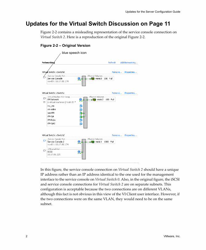
Updates for the Server Configuration Guide
2 VMware, Inc.
Updates for the Virtual Switch Discussion on Page 11Figure 2‐2 contains a misleading representation of the service console connection on Virtual Switch 2. Here is a reproduction of the original Figure 2‐2.
Figure 2-2 – Original Version
In this figure, the service console connection on Virtual Switch 2 should have a unique IP address rather than an IP address identical to the one used for the management interface to the service console on Virtual Switch 0. Also, in the original figure, the iSCSI and service console connections for Virtual Switch 2 are on separate subnets. This configuration is acceptable because the two connections are on different VLANs, although this fact is not obvious in this view of the VI Client user interface. However, if the two connections were on the same VLAN, they would need to be on the same subnet.
blue speech icon
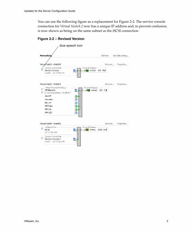
VMware, Inc. 3
Updates for the Server Configuration Guide
You can use the following figure as a replacement for Figure 2‐2. The service console connection for Virtual Switch 2 now has a unique IP address and, to prevent confusion, is now shown as being on the same subnet as the iSCSI connection.
Figure 2-2 – Revised Version
blue speech icon
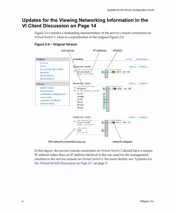
Updates for the Server Configuration Guide
4 VMware, Inc.
Updates for the Viewing Networking Information in the VI Client Discussion on Page 14
Figure 2‐4 contains a misleading representation of the service console connection on Virtual Switch 2. Here is a reproduction of the original Figure 2‐4.
Figure 2-4 – Original Version
In this figure, the service console connection on Virtual Switch 2 should have a unique IP address rather than an IP address identical to the one used for the management interface to the service console on Virtual Switch 0. For more details, see “Updates for the Virtual Switch Discussion on Page 11” on page 2.
IP address vSwitch
VM network properties pop-up network adapter
port group
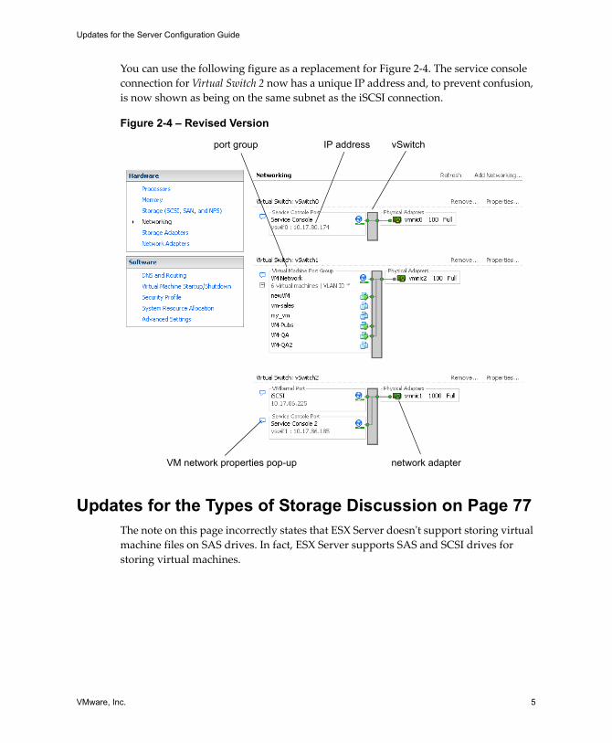
VMware, Inc. 5
Updates for the Server Configuration Guide
You can use the following figure as a replacement for Figure 2‐4. The service console connection for Virtual Switch 2 now has a unique IP address and, to prevent confusion, is now shown as being on the same subnet as the iSCSI connection.
Figure 2-4 – Revised Version
Updates for the Types of Storage Discussion on Page 77The note on this page incorrectly states that ESX Server doesnʹt support storing virtual machine files on SAS drives. In fact, ESX Server supports SAS and SCSI drives for storing virtual machines.
IP address vSwitch
VM network properties pop-up network adapter
port group
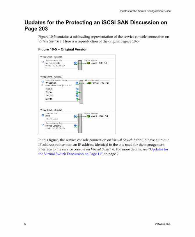
Updates for the Server Configuration Guide
6 VMware, Inc.
Updates for the Protecting an iSCSI SAN Discussion on Page 203
Figure 10‐5 contains a misleading representation of the service console connection on Virtual Switch 2. Here is a reproduction of the original Figure 10‐5.
Figure 10-5 – Original Version
In this figure, the service console connection on Virtual Switch 2 should have a unique IP address rather than an IP address identical to the one used for the management interface to the service console on Virtual Switch 0. For more details, see “Updates for the Virtual Switch Discussion on Page 11” on page 2.
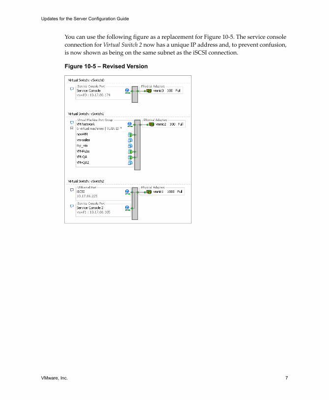
VMware, Inc. 7
Updates for the Server Configuration Guide
You can use the following figure as a replacement for Figure 10‐5. The service console connection for Virtual Switch 2 now has a unique IP address and, to prevent confusion, is now shown as being on the same subnet as the iSCSI connection.
Figure 10-5 – Revised Version

Updates for the Server Configuration Guide
8 VMware, Inc.