Embed Size (px)
Citation preview
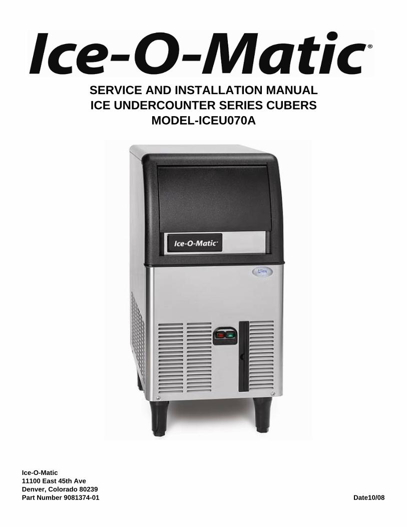
Ice-O-Matic11100 East 45th AveDenver, Colorado 80239Part Number 9081374-01 Date10/08
SERVICE AND INSTALLATION MANUALICE UNDERCOUNTER SERIES CUBERS
MODEL-ICEU070A

INTRODUCTION
This manual provides the specifications and thestep-by-step procedures for the installation,startup, operation, maintenance and cleaning forthe ICEU070A ice machine.
NOTE. To retain the safety and performance builtinto this ice machine, it is important that installationand maintenance be conducted in the manneroutlined in this manual.
ICEU070A
Page 1
Table of Contents
Specifications · · · · · · · · · · · · · · · · · · · · · · · · · · · · · · · · · · · · · · · · · · Page 2
General Information And Installation · · · · · · · · · · · · · · · · · · · · · · · · · · · · · · Page 3
Water Supply And Drain Connections · · · · · · · · · · · · · · · · · · · · · · · · · · · · · · Page 4
Final Check List · · · · · · · · · · · · · · · · · · · · · · · · · · · · · · · · · · · · · · · · · Page 5
Operating Instructions · · · · · · · · · · · · · · · · · · · · · · · · · · · · · · · · · · · · · · Page 6
Operational Checks · · · · · · · · · · · · · · · · · · · · · · · · · · · · · · · · · · · · · · · Page 7
Component Description · · · · · · · · · · · · · · · · · · · · · · · · · · · · · · · · · · · · · Page 8
Operation - Electrical Sequence · · · · · · · · · · · · · · · · · · · · · · · · · · · · · · · · · Page 9
Freeze Cycle· · · · · · · · · · · · · · · · · · · · · · · · · · · · · · · · · · · · · · · · · · · Page 10
Cleaning Switch · · · · · · · · · · · · · · · · · · · · · · · · · · · · · · · · · · · · · · · · · Page 11
Service Diagnosis · · · · · · · · · · · · · · · · · · · · · · · · · · · · · · · · · · · · · · · · Page 12
Service Diagnosis · · · · · · · · · · · · · · · · · · · · · · · · · · · · · · · · · · · · · · · · Page 13
Maintenance And Cleaning Instructions · · · · · · · · · · · · · · · · · · · · · · · · · · · · · Page 14
Cleaning Water System · · · · · · · · · · · · · · · · · · · · · · · · · · · · · · · · · · · · · Page 15
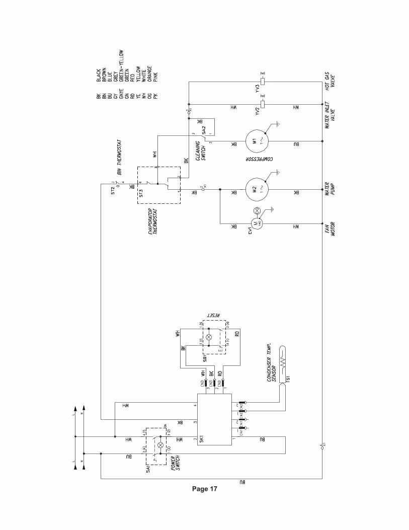
Wiring Diagram · · · · · · · · · · · · · · · · · · · · · · · · · · · · · · · · · · · · · · · · · Page 17
Warranty · · · · · · · · · · · · · · · · · · · · · · · · · · · · · · · · · · · · · · · · Page 18
Specifications
The ice machine must be installed indoors in acontrolled environment.
Minimum Maximum
Air Temp 500F. 95
0F.
Water Temp 400F. 100
0F.
Water Pressure 20 PSI 80 PSI
Voltage 103.5 126.5
Operating the ice machine outside of the abovelimitations, or outdoors, is potentially damaging tothe machine, and it is misuse of the machine. Thismay void the warranty.
Ice-O-Matic ice machines are designed andmanufactured with the highest regard for safetyand performance. They meet or exceed thestandards of agencies like NSF and UL.
Ice-O-Matic assumes no liability or responsibility ofany kind for products manufactured by Ice-O-Maticthat have been altered in any way, including theuse of any part and/or other components notspecifically approved by Ice-O-Matic.
Ice-O-Matic reserves the right to make designchanges and/or improvements at any time.Specifications and design are subject to changewithout notice.
UNPACKING AND INSPECTION
1. Call your authorized Ice-O-Matic Distributor orDealer for proper installation.
2. Remove the front panel of the unit and inspectfor any concealed damage. Notify carrier of yourclaim for the concealed damage.
3. Check that refrigerant lines do not rub against ortouch other lines or surfaces, and that the fanblade moves freely.
4. Check that the compressor fits snugly onto all itsmounting pads.
5. Remove all internal support packing andmasking tape.
ICEU070A
Page 2
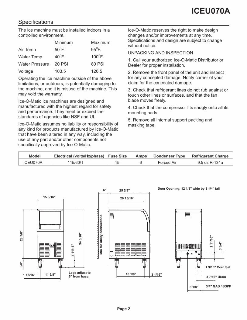
15 3/16"
25 5/8"
16 1/8" 3 1/16"11 5/8"1 13/16"
8 1/8"
6"
41
1/1
6" 3
43
/16
"
28
7/8
"5
/8"
Min
for
uti
lity
co
nn
ecti
on
s
21
1/1
6"
33
/4"
1 9/16" Cord Set
3 7/16" Drain
3/4" GAS / BSPP
20 15/16"
Door Opening: 12 1/8" wide by 8 1/4" tall
Legs adjust to6" from base.
Model Electrical (volts/Hz/phase) Fuse Size Amps Condenser Type Refrigerant Charge
ICEU070A 115/60/1 15 6 Forced Air 9.5 oz R-134a
General Information And Installation
This model is supplied from the factory completelypre-wired and requires only electrical powerconnections to the wire cord provided at rear of theunit.
Make sure that the ice machine is connected to itsown circuit and individually fused (see data platefor maximum fuse size). This is a cord-connectedunit designed for 115 volt AC power, with amaximum fuse size of 15 amps.
Low voltage can cause improper operation andmay be responsible for serious damage to theoverload switch and motor windings that is notcovered by warranty.
NOTE. All external wiring should conform tonational, state and local standards and regulations.
Check voltage on the line and the ice maker’s dataplate before connecting the unit. Extension cordsmust not be used.
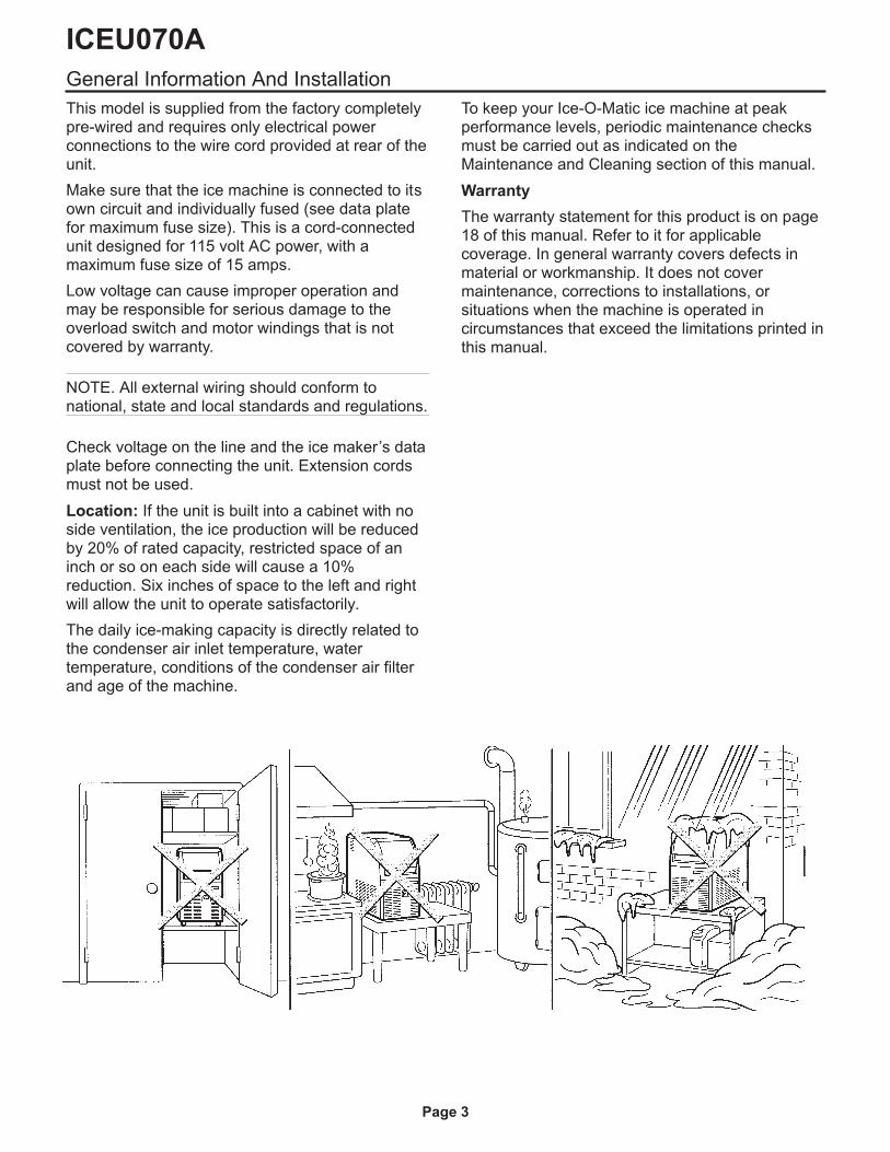
Location: If the unit is built into a cabinet with noside ventilation, the ice production will be reducedby 20% of rated capacity, restricted space of aninch or so on each side will cause a 10%reduction. Six inches of space to the left and rightwill allow the unit to operate satisfactorily.
The daily ice-making capacity is directly related tothe condenser air inlet temperature, watertemperature, conditions of the condenser air filterand age of the machine.
To keep your Ice-O-Matic ice machine at peakperformance levels, periodic maintenance checksmust be carried out as indicated on theMaintenance and Cleaning section of this manual.
Warranty
The warranty statement for this product is on page18 of this manual. Refer to it for applicablecoverage. In general warranty covers defects inmaterial or workmanship. It does not covermaintenance, corrections to installations, orsituations when the machine is operated incircumstances that exceed the limitations printed inthis manual.
ICEU070A
Page 3
Water Supply And Drain Connections
General
When choosing the water supply for the ice cuberconsideration should be given to:
a) Length of run
b) Water clarity and purity
c) Adequate water supply pressure
Low water pressure, below 20 psi may cause amalfunction.
Water containing excessive minerals will tend toproduce cloudy colored ice cubes, plus scalebuild-up on parts of the water system.
Water Supply
The recommended water supply line is a 3/8" o.d.copper tube, the water pressure must have aminimum incoming pressure of 20 psig.
Connect the tubing to the 3/4" GAS / BSPP threadwater inlet fitting at the back of the ice maker. Anadapter is available, the part numbers are: WaterInlet Adapter-1011411-64 and Water Inlet AdapterO-Ring-1011411-65.
Water Drain
The recommended drain tube is a plastic or flexibletube with 18 mm (3/4") I.D. which runs to an opentrapped and vented drain.
Note: Although soft, easily kinked vinyl tubing isnot recommended for a drain, a short length of ¾”ID vinyl tubing is required to connect a rigid draintube to the 20 mm (25/32”) fitting on the back ofthe machine.
NOTE. The water supply and the water drain mustbe installed to conform to the local code. In somecase a licensed plumber and/or a plumbing permitis required.
ICEU070A
Page 4
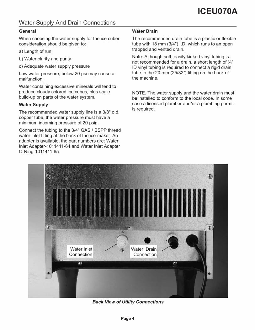
Back View of Utility Connections
Water InletConnection
Water DrainConnection
Final Check List
1. Is the unit in a room where ambienttemperatures are above a minimum of 10oC (50
oF)
even in winter months?
2. Is there at least a 15 cm (6") clearance aroundthe unit for proper air circulation?
3. Is the unit level? (IMPORTANT)
4. Have all the electrical and plumbing connectionsbeen made, and is the water supply shut-off valveopen?
5. Has the voltage been tested and checkedagainst the data plate rating?
6. Has the water supply pressure been checked toensure a water pressure of at least 20 psi.
7. Check all refrigerant lines and conduit lines toguard against vibrations and possible failure.
8. Have the bolts holding the compressor downbeen checked to ensure that the compressor issnugly fitted onto the mounting pads?
9. Have the bin liner and cabinet been wipedclean?
10. Has the owner/user been given the UserManual and been instructed on the importance ofperiodic maintenance checks?
11. Has the Manufacturer’s registration card beenfilled in properly? Check for correct model andserial number against the serial plate and mail theregistration card to the factory.
12. Has the owner been given the name and thephone number of the authorized Ice-O-maticService Agency serving him?
ICEU070A
Page 5
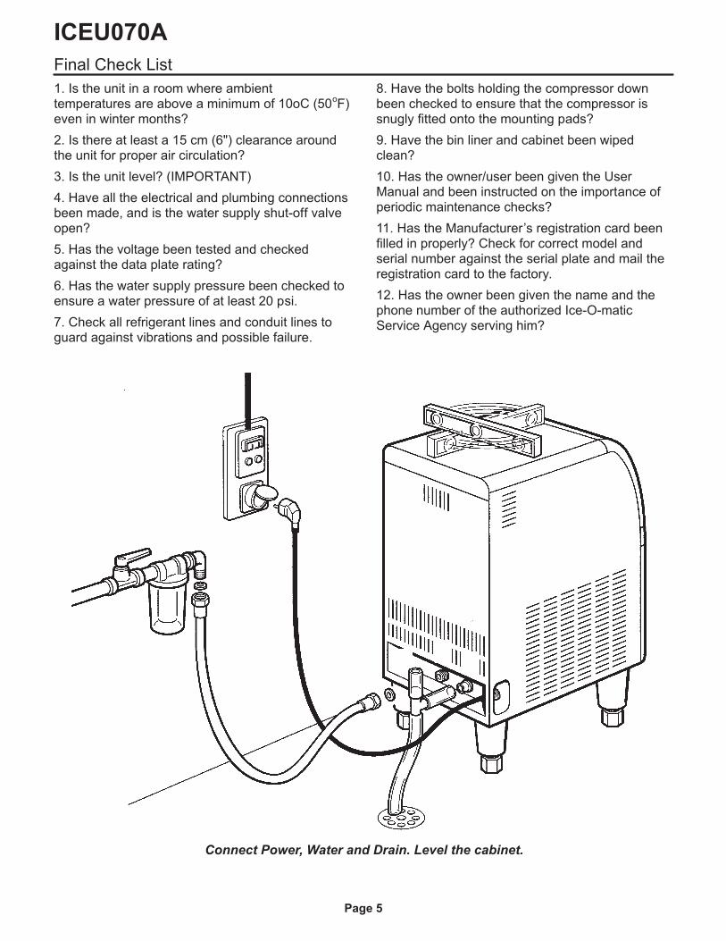
Connect Power, Water and Drain. Level the cabinet.
Operating Instructions
Start Up
After having correctly installed the ice maker andcompleted the plumbing and electricalconnections, perform the following “Start-up”procedure.
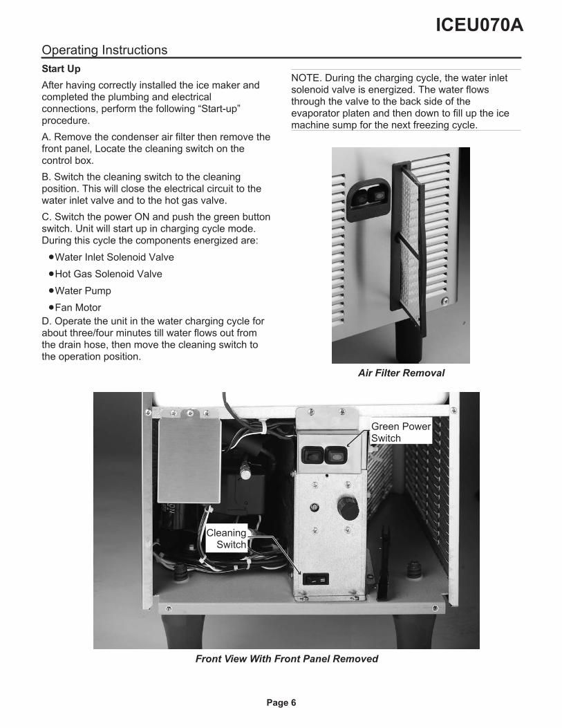
A. Remove the condenser air filter then remove thefront panel, Locate the cleaning switch on thecontrol box.
B. Switch the cleaning switch to the cleaningposition. This will close the electrical circuit to thewater inlet valve and to the hot gas valve.
C. Switch the power ON and push the green buttonswitch. Unit will start up in charging cycle mode.During this cycle the components energized are:
�Water Inlet Solenoid Valve
�Hot Gas Solenoid Valve
�Water Pump
�Fan Motor
D. Operate the unit in the water charging cycle forabout three/four minutes till water flows out fromthe drain hose, then move the cleaning switch tothe operation position.
NOTE. During the charging cycle, the water inletsolenoid valve is energized. The water flowsthrough the valve to the back side of theevaporator platen and then down to fill up the icemachine sump for the next freezing cycle.
ICEU070A
Page 6
Air Filter Removal
Front View With Front Panel Removed
CleaningSwitch
Green PowerSwitch
Operational Checks
E. The unit now starts its first freezing cycle withthe following components in operation:
�Compressor
�Water Pump
�Fan Motor
F. Look through the ice discharge opening andconfirm that the spray system is correctly seatedand that the water jets uniformly reach the interiorof the inverted cup molds; also make sure that theplastic curtain is hanging freely and excessivewater is not flowing through it.
G. During the freeze cycle, the evaporator willremove heat from the water sprayed into the icemaking molds and warm air will be dischargedfrom the cabinet.
H. When the evaporator temperature reaches apreset value the evaporator thermostat or cubesize control changes its contacts; the freezingcycle ends and starts the defrost or harvest cycle.
Freezing time will range between 20 and 22minutes in a 70
oF ambient temperature. Longer
time for temperature above, shorter when below.Average complete cycle range is about 23 to 25minutes.
I. Check, during the first defrost/harvest cycle, thatthe incoming water flows correctly into the sump tore-fill it and the surplus overflows through theoverflow drain tube.
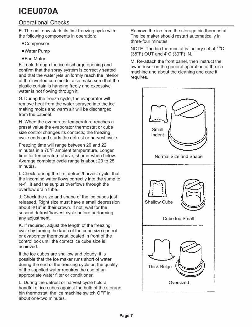
J. Check the size and shape of the ice cubes justreleased. Right size must have a small depressionabout 3/16” in their crown. If not, wait for thesecond defrost/harvest cycle before performingany adjustment.
K. If required, adjust the length of the freezingcycle by turning the knob of the cube size controlor evaporator thermostat located in front of thecontrol box until the correct ice cube size isachieved.
If the ice cubes are shallow and cloudy, it ispossible that the ice maker runs short of waterduring the end of the freezing cycle or, the qualityof the supplied water requires the use of anappropriate water filter or conditioner.
L. During the defrost or harvest cycle hold ahandful of ice cubes against the bulb of the storagebin thermostat; the ice machine switch OFF inabout one-two minutes.
Remove the ice from the storage bin thermostat.The ice maker should restart automatically inthree-four minutes.
NOTE. The bin thermostat is factory set at 1oC
(35oF) OUT and 4
oC (39
oF) IN.
M. Re-attach the front panel, then instruct theowner/user on the general operation of the icemachine and about the cleaning and care itrequires.
ICEU070A
Page 7
SmallIndent
Normal Size and Shape
Shallow Cube
Cube too Small
Thick Bulge
Oversized
Component Description
Water Pump
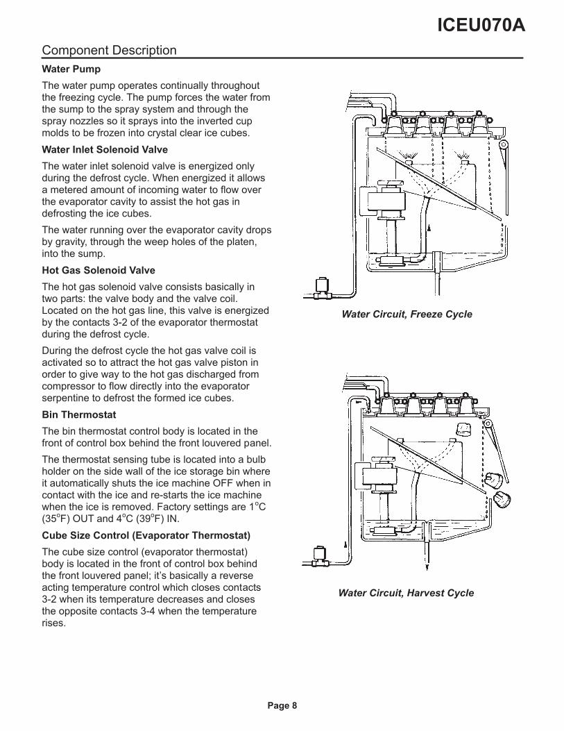
The water pump operates continually throughoutthe freezing cycle. The pump forces the water fromthe sump to the spray system and through thespray nozzles so it sprays into the inverted cupmolds to be frozen into crystal clear ice cubes.
Water Inlet Solenoid Valve
The water inlet solenoid valve is energized onlyduring the defrost cycle. When energized it allowsa metered amount of incoming water to flow overthe evaporator cavity to assist the hot gas indefrosting the ice cubes.
The water running over the evaporator cavity dropsby gravity, through the weep holes of the platen,into the sump.
Hot Gas Solenoid Valve
The hot gas solenoid valve consists basically intwo parts: the valve body and the valve coil.Located on the hot gas line, this valve is energizedby the contacts 3-2 of the evaporator thermostatduring the defrost cycle.
During the defrost cycle the hot gas valve coil isactivated so to attract the hot gas valve piston inorder to give way to the hot gas discharged fromcompressor to flow directly into the evaporatorserpentine to defrost the formed ice cubes.
Bin Thermostat
The bin thermostat control body is located in thefront of control box behind the front louvered panel.
The thermostat sensing tube is located into a bulbholder on the side wall of the ice storage bin whereit automatically shuts the ice machine OFF when incontact with the ice and re-starts the ice machinewhen the ice is removed. Factory settings are 1
oC
(35oF) OUT and 4
oC (39
oF) IN.
Cube Size Control (Evaporator Thermostat)
The cube size control (evaporator thermostat)body is located in the front of control box behindthe front louvered panel; it’s basically a reverseacting temperature control which closes contacts3-2 when its temperature decreases and closesthe opposite contacts 3-4 when the temperaturerises.
ICEU070A
Page 8
Water Circuit, Freeze Cycle
Water Circuit, Harvest Cycle
Operation - Electrical Sequence
The following charts illustrate which switches andcomponents are ON or OFF during the two phasesof the icemaking cycle.
Refer to the wiring diagram for reference.
FREEZING CYCLEElectrical components ON OFF
Compressor •
Water Pump •
Fan Motor •
Hot Gas Valve •
Inlet Water Valve •
Electrical Controls CLOSE OPEN
Evaporator Thermostat (contacts 3-4) •
Evaporator Thermostat (contacts 3-2) •
Bin Thermostat •
HARVEST CYCLEElectrical components ON OFF
Compressor •
Water Pump •
Fan Motor (Air cooled only) •
Hot Gas Valve •
Inlet Water Valve •
Electrical Controls CLOSE OPEN
Evaporator Thermostat (contacts 3-4) •
Evaporator Thermostat (contacts 3-2) •
Bin Thermostat •
ICEU070A
Page 9
Freeze Cycle
Average Discharge Pressure
�A/C: 100 to 155 PSIG
Suction Pressure
�End Freeze Cycle: 0 to 1.5 PSIG
Refrigerant Metering Device:
�Capillary tube
Refrigerant Charge (R-134a)
�9.5 oz.
The thermostat sensing bulb is located into aplastic tube (bulb holder) secured by two clipsdirectly to the evaporator serpentine. This controldetermines the length of the freezing cycle andcorrespondingly the size of the cubes.
A lower setting will produce a larger cube(oversize) while a higher setting a smaller cuber(shallow size).
When closed on contacts 3-2 it activates thedefrost or harvest cycle components. The cubesize control is pre-set at the factory (knob in theblack dot position) and doesn’t require anyadjustment when the ambient temperature remainsbetween 15
oC and 30
oC (60
oF and 90
oF).
Fan Motor
The fan motor is electrically connected in parallelto the water pump and it operates continuouslyonly during the freezing cycle keeping the properhead pressure by circulating air through thecondenser fins.
Compressor
The hermetic compressor is used to circulaterefrigerant throughout the entire system. Itcompresses the low pressure refrigerant vaporcausing its temperature to rise and become highpressure hot vapor (hot gas) which is thenreleased through the discharge valve.
Water Spray System
Sprays the water into each individual cup to befrozen into ice.
ICEU070A
Page 10
Cleaning Switch
Located on the bottom side of the control box, it isused to energize the water inlet and the hot gasvalves to fill the sump of the machine with waterwhen needed.
Green Master Switch Push Button
Located in the front of the machine it’s used toswitch ON and OFF the unit by pushing its greenpush button. When ON, its green light is ON.
Red Alarm/Re-Set Push Button
Located in the front of the machine (just beside theMaster Switch) it works in conjunction with theCleaning Remind Board and it’s activated when:
1. ON steady with machine in OFF mode
Condensing temperature is higher then 70oC or
158oF. (air cooled version)
2. Blinking twice and repeat with machine in OFFmode
Condenser sensor out of order.
3. ON steady with machine in ON mode
Condenser air filter needs to be cleaned.
4. Slow blinking with machine in ON mode.
Water system needs to be cleaned.
In the first case the machine can be Re-Set bypushing and holding the Red Alarm Re-Set Buttonfor 5 seconds till the Red Light is OFF.
In the second case, first replace the condensersensor then, push and hold the Red Re-Set Buttonfor 5 seconds.
Cleaning Reminder PC Board
Located on the front left side of the machine, itworks in conjunction with the condenser sensorand the Red Alarm Re-Set Push Button.
It consists of
�Printed Circuit Board with a step downtransformer (115V - 12V)
�Relay
�Dip Switch with two keys
�Jumper for the set up of the Cut OFF/Alarmcondensing temperature (70oC 158oF.- jumperOUT - for air cooled)
�green four wire connector for power IN andOUT
�Red socket for the Water Level Sensor (futureuse)
�Black socket for the Condenser Sensor and
�White socket for the Red Alarm Re-Set PushButton
The main function of this PC Board is to switch themachine OFF when the condensing temperature istoo high or signal the need for cleaning thecondenser air filter or the water system. The timebetween the signal for the cleaning of the watersystem can be modified according to the setting ofthe two Dip Switches as below:
Time 1 2
1 Month On On
3 Months Off On
6 Months On Off
1 Year Off Off
Once the water system has been cleaned, pushand hold the Red Alarm Re-Set Button for morethen 20 seconds until it starts to blink. That willreset the control.
Condenser Air Filter
It is located in front of the air cooled condenser. Itcan be removed by pulling it through the openingin the front panel for cleaning or replacing. A lowerplastic guide, installed inside the unit, is used forthe correct sliding and location of the air filter.
Condenser Sensor
The condenser temperature sensor probe, locatedwithin the condenser fins detects the condensertemperature variations and signals them bysupplying current, at low voltage, to the P.C.BOARD.
In case the condenser temperature rises andreaches 70
oC (160
oF) – the control system will
cause an immediate and total stop of themachine’s operation.
ICEU070A
Page 11
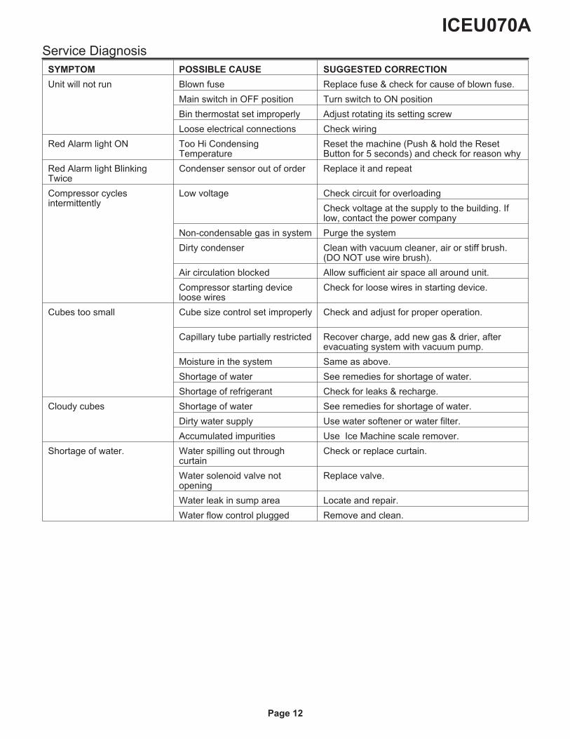
Service Diagnosis
SYMPTOM POSSIBLE CAUSE SUGGESTED CORRECTION
Unit will not run Blown fuse Replace fuse & check for cause of blown fuse.
Main switch in OFF position Turn switch to ON position
Bin thermostat set improperly Adjust rotating its setting screw
Loose electrical connections Check wiring
Red Alarm light ON Too Hi CondensingTemperature
Reset the machine (Push & hold the ResetButton for 5 seconds) and check for reason why
Red Alarm light BlinkingTwice
Condenser sensor out of order Replace it and repeat
Compressor cyclesintermittently
Low voltage Check circuit for overloading
Check voltage at the supply to the building. Iflow, contact the power company
Non-condensable gas in system Purge the system
Dirty condenser Clean with vacuum cleaner, air or stiff brush.(DO NOT use wire brush).
Air circulation blocked Allow sufficient air space all around unit.
Compressor starting deviceloose wires
Check for loose wires in starting device.
Cubes too small Cube size control set improperly Check and adjust for proper operation.
Capillary tube partially restricted Recover charge, add new gas & drier, afterevacuating system with vacuum pump.
Moisture in the system Same as above.
Shortage of water See remedies for shortage of water.
Shortage of refrigerant Check for leaks & recharge.
Cloudy cubes Shortage of water See remedies for shortage of water.
Dirty water supply Use water softener or water filter.
Accumulated impurities Use Ice Machine scale remover.
Shortage of water. Water spilling out throughcurtain
Check or replace curtain.
Water solenoid valve notopening
Replace valve.
Water leak in sump area Locate and repair.
Water flow control plugged Remove and clean.
ICEU070A
Page 12
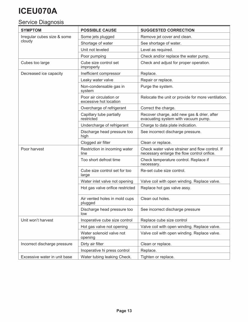
Service Diagnosis
SYMPTOM POSSIBLE CAUSE SUGGESTED CORRECTION
Irregular cubes size & somecloudy
Some jets plugged Remove jet cover and clean.
Shortage of water See shortage of water.
Unit not leveled Level as required.
Poor pumping Check and/or replace the water pump.
Cubes too large Cube size control setimproperly
Check and adjust for proper operation.
Decreased ice capacity Inefficient compressor Replace.
Leaky water valve Repair or replace.
Non-condensable gas insystem
Purge the system.
Poor air circulation orexcessive hot location
Relocate the unit or provide for more ventilation.
Overcharge of refrigerant Correct the charge.
Capillary tube partiallyrestricted
Recover charge, add new gas & drier, afterevacuating system with vacuum pump.
Undercharge of refrigerant Charge to data plate indication.
Discharge head pressure toohigh
See incorrect discharge pressure.
Clogged air filter Clean or replace.
Poor harvest Restriction in incoming waterline
Check water valve strainer and flow control. Ifnecessary enlarge the flow control orifice.
Too short defrost time Check temperature control. Replace ifnecessary.
Cube size control set for toolarge
Re-set cube size control.
Water inlet valve not opening Valve coil with open winding. Replace valve.
Hot gas valve orifice restricted Replace hot gas valve assy.
Air vented holes in mold cupsplugged
Clean out holes.
Discharge head pressure toolow
See incorrect discharge pressure
Unit won’t harvest Inoperative cube size control Replace cube size control
Hot gas valve not opening Valve coil with open winding. Replace valve.
Water solenoid valve notopening
Valve coil with open winding. Replace valve.
Incorrect discharge pressure Dirty air filter Clean or replace.
Inoperative hi press control Replace.
Excessive water in unit base Water tubing leaking Check. Tighten or replace.
ICEU070A
Page 13

Maintenance And Cleaning Instructions
GENERAL
The periods and the procedures for maintenanceand cleaning are given as guides and are not to beconstrued as absolute or invariable. Cleaning,especially, will vary depending upon local waterand ambient conditions and the ice volumeproduced; and, each ice machine must bemaintained individually, in accordance with itsparticular location requirements.
Ice Machine
The following maintenance should be scheduled atleast two times per year on these ice machines.
1. Check and/or replace the water filter (if used).
2. Check that the ice machine is leveled in side toside and in front to rear directions.
3. Check for water leaks and tighten drain lineconnections. Pour water down bin drain line to besure that drain line is open and clear.
4. Check size, condition and texture of ice cubes.Perform adjustment of cube size control asrequired.
5. Check the bin thermostat to test shut-off.
Put a scoop full of ice cubes in contact with the binthermostat bulb for at least one minute.
This should cause the ice maker to shut off. Withinfew seconds after the removal of the ice from binthermostat bulb, the ice machine restarts.
NOTE. Within minutes after the ice is removedfrom the bulb holder tube, the sensing bulb insidethe tube will warm up and cause the ice machineto restart. This control is factory set and should notbe reset until testing is performed.
6. Check for refrigerant leaks.
NOTE. Standard equipped with an air condenserfilter as well as a Cleaning Reminder Board toremind to the end user the need for the cleaning ofthe air filter or of the water system (Red AlarmLight ON Steady or Blinking respectively withmachine in operation).
Clean - Replace Of Air Condenser Filter
1. Withdraw the air filter from the front through theopening of the front panel.
2. Remove the front panel.
3. Blow pressurized air on the opposite direction ofthe condenser air flow so to remove the dustaccumulated. If pressurized air is not available,use tap water always in the counter flow airdirection. Once cleaned shake it so to removemost of the accumulated water, then dry it using anhair dryer.
NOTE. In case the air filter strainer is damagedreplace it with a new one.
4. Return the front panel to its normal position.
5. Install filter by pushing it through the front panelopening.
ICEU070A
Page 14
Cleaning Water System
1. Remove the ice from the bin.
2. Remove the air filter and then the front panel.
3. Rotate control knob counter clockwise to the Offposition.
4. Turn off the water supply to the ice machine.
5. Remove top panel.
6. Remove plastic panel (evaporator cover) thatcovers evaporator section.
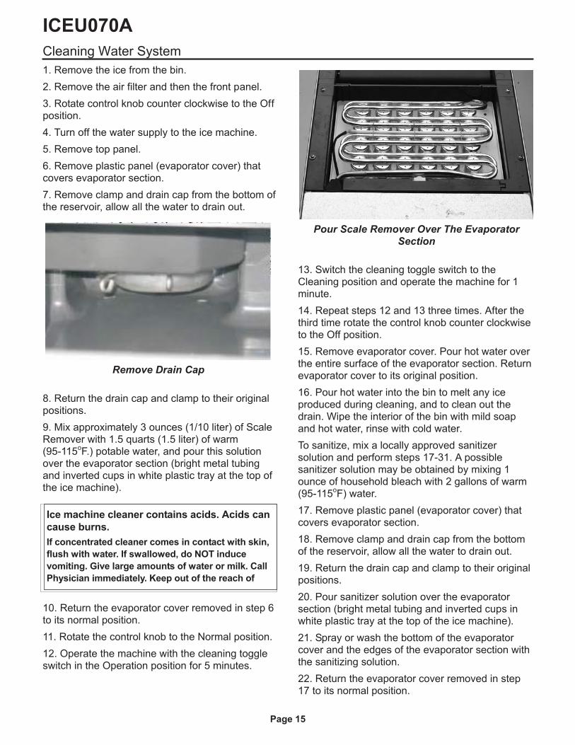
7. Remove clamp and drain cap from the bottom ofthe reservoir, allow all the water to drain out.
8. Return the drain cap and clamp to their originalpositions.
9. Mix approximately 3 ounces (1/10 liter) of ScaleRemover with 1.5 quarts (1.5 liter) of warm(95-115
oF.) potable water, and pour this solution
over the evaporator section (bright metal tubingand inverted cups in white plastic tray at the top ofthe ice machine).
10. Return the evaporator cover removed in step 6to its normal position.
11. Rotate the control knob to the Normal position.
12. Operate the machine with the cleaning toggleswitch in the Operation position for 5 minutes.
13. Switch the cleaning toggle switch to theCleaning position and operate the machine for 1minute.
14. Repeat steps 12 and 13 three times. After thethird time rotate the control knob counter clockwiseto the Off position.
15. Remove evaporator cover. Pour hot water overthe entire surface of the evaporator section. Returnevaporator cover to its original position.
16. Pour hot water into the bin to melt any iceproduced during cleaning, and to clean out thedrain. Wipe the interior of the bin with mild soapand hot water, rinse with cold water.
To sanitize, mix a locally approved sanitizersolution and perform steps 17-31. A possiblesanitizer solution may be obtained by mixing 1ounce of household bleach with 2 gallons of warm(95-115
oF) water.
17. Remove plastic panel (evaporator cover) thatcovers evaporator section.
18. Remove clamp and drain cap from the bottomof the reservoir, allow all the water to drain out.
19. Return the drain cap and clamp to their originalpositions.
20. Pour sanitizer solution over the evaporatorsection (bright metal tubing and inverted cups inwhite plastic tray at the top of the ice machine).
21. Spray or wash the bottom of the evaporatorcover and the edges of the evaporator section withthe sanitizing solution.
22. Return the evaporator cover removed in step17 to its normal position.
ICEU070A
Page 15
Remove Drain Cap
Pour Scale Remover Over The EvaporatorSection
Ice machine cleaner contains acids. Acids can
cause burns.
If concentrated cleaner comes in contact with skin,
flush with water. If swallowed, do NOT induce
vomiting. Give large amounts of water or milk. Call
Physician immediately. Keep out of the reach of
23. Rotate the control knob to the Normal position.
24. Operate the machine with the cleaning toggleswitch in the Operation position for 4 minutes.
25. Switch the cleaning toggle switch to theCleaning position and operate the machine for 1minute.
26. Repeat steps 23 and 24 five times. After thefifth time rotate the control knob counter clockwiseto the Off position.
27. Remove evaporator cover. Pour sanitizersolution over the entire surface of the evaporatorsection and wash or spray the evaporator coverbottom with sanitizer. Return evaporator cover toits original position.
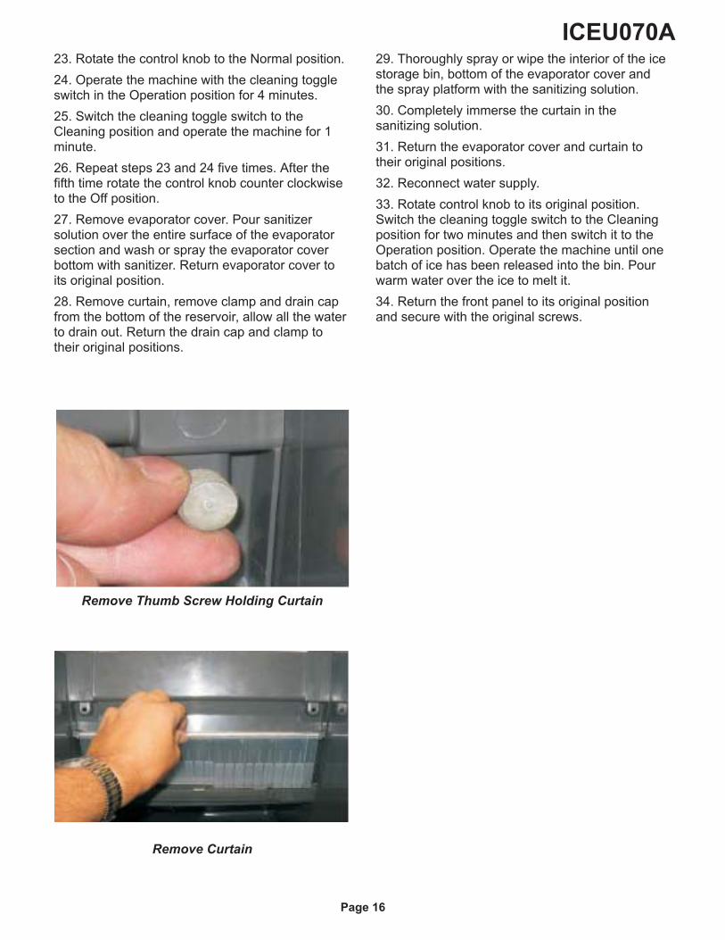
28. Remove curtain, remove clamp and drain capfrom the bottom of the reservoir, allow all the waterto drain out. Return the drain cap and clamp totheir original positions.
29. Thoroughly spray or wipe the interior of the icestorage bin, bottom of the evaporator cover andthe spray platform with the sanitizing solution.
30. Completely immerse the curtain in thesanitizing solution.
31. Return the evaporator cover and curtain totheir original positions.
32. Reconnect water supply.
33. Rotate control knob to its original position.Switch the cleaning toggle switch to the Cleaningposition for two minutes and then switch it to theOperation position. Operate the machine until onebatch of ice has been released into the bin. Pourwarm water over the ice to melt it.
34. Return the front panel to its original positionand secure with the original screws.
ICEU070A
Page 16
Remove Thumb Screw Holding Curtain
Remove Curtain
Page 17

Ice-O-Matic
Parts and Labor
Domestic & International Limited Warranty
Mile High Equipment LLC (the “Company”) warrants Ice-O-Matic brand ice machines, ice dispensers, remote condensers, water filters, and ice storage bins
to the end customer against defects in material and factory workmanship for the following:
� Cube ice machines,”GEM” model compressed ice
machines ,” MFI” model flake ice machines and remote
condensers. - Thirty-six (36) months parts and labor
� Ice storage bins -Twenty-four (24) month parts and labor
� “EF” and “EMF” model flake ice machines - Twenty-four
(24) months parts and labor
� IOD model dispensers - Twenty-four (24) months parts, Twelve (12) months labor
� CD model dispensers - Thirty-six (36) months parts and
labor
� Water filter systems - Twelve (12) months parts and labor (not including filter
cartridges)
An additional twenty-four (24) month warranty on parts (excluding labor) will be extended to all cube ice machine evaporator plates and compressors, “GEM”model compressed ice machine compressors, and “MFI” model flake ice machine compressors from the date of original installation. An additional thirty-six(36) month warranty on parts (excluding labor) will be extended to all “EF” and “EMF” model flake ice machine compressors from the date of originalinstallation. The company will replace EXW (Incoterms 2000) the Company plant or, EXW (Incoterms 2000) the Company-authorized distributor, without costto the Customer, that part of any such machine that becomes defective. In the event that the Warranty Registration Card indicating the installation date hasnot been returned to Ice-O-Matic, the warranty period will begin on the date of shipment from the Company. Irrespective of the actual installation date, the
product will be warranted for a maximum of seventy-two (72) months from date of shipment from the Company.
ICE-model cube ice machines which are registered in the Water Filter Extended Warranty Program will receive a total of eighty-four (84) months parts and
labor coverage on the evaporator plate from the date of original installation. Water filters must be installed at the time of installation and registered with the
Company at that time. Water filter cartridges must be changed every six (6) months and that change reported to the Company to maintain the extended
evaporator warranty.
No replacement will be made for any part or assembly which (I) has been subject to an alteration or accident; (II) was used in any way which, in the
Company’s opinion, adversely affects the machine’s performance; (III) is from a machine on which the serial number has been altered or removed; or, (IV)
uses any replacement part not authorized by the Company. This warranty does not apply to destruction or damage caused by unauthorized service, using
other than Ice-O-Matic authorized replacements, risks of transportation, damage resulting from adverse environmental or water conditions, accidents,
misuse, abuse, improper drainage, interruption in the electrical or water supply, charges related to the replacement of non-defective parts or components,
damage by fire, flood, or acts of God.
This warranty is valid only when installation, service, and preventive maintenance are performed by a Company-authorized distributor, a Company-authorized
service agency, or a Company Regional Manager. The Company reserves the right to refuse claims made for ice machines or bins used in more than one
location. This Limited Warranty does not cover ice bills, normal maintenance, after-install adjustments, and cleaning.
Limitation of Warranty
This warranty is valid only for products produced and shipped from the Company after January, 2007. A product produced or installed before that date shall
be covered by the Limited Warranty in effect at the date of its shipment. The liability of the Company for breach of this warranty shall, in any case, be limited
to the cost of a new part to replace any part, which proves to be defective. The Company makes no representations or warranties of any character as to
acessories or auxiliary equipment not manufactured by the Company. REPAIR OR REPLACEMENT AS PROVIDED UNDER THIS WARRANTY IS THE
EXCLUSIVE REMEDY OF THE CUSTOMER. MILE HIGH EQUIPMENT SHALL NOT BE LIABLE FOR ANY INCIDENTAL OR CONSEQUENTIAL
DAMAGES FOR BREACH OF ANY EXPRESS OR IMPLIED WARRANTY ON THIS PRODUCT. EXCEPT TO THE EXTENT PROHIBITED BY APPLICABLE
LAW, ANY IMPLIED WARRANTY OR MERCHANTABILITY OR FITNESS FOR A PARTICULAR PURPOSE ON THIS PRODUCT IS LIMITED IN DURATION
TO THE LENGTH OF THIS WARRANTY.
Filing a Claim
All claims for reimbursement must be received at the factory within 90 days from date of service to be eligible for credit. All claims outside this time
period will be void. The model, the serial number and, if necessary, proof of installation, must be included in the claim. Claims for labor to replace defective
parts must be included with the part claim to receive consideration. Payment on claims for labor will be limited to the published labor time allowance hours in
effect at the time of repair. The Company may elect to require the return of components to validate a claim. Any defective part returned must be shipped to
the Company or the Company-authorized distributor, transportation charges pre-paid, and properly sealed and tagged. The Company does not assume any
responsibility for any expenses incurred in the field incidental to the repair of equipment covered by this warranty. The decision of the Company with respect
to repair or replacement of a part shall be final. No person is authorized to give any other warranties or to assume any other liability on the Company’s behalf
unless done in writing by an officer of the Company.
GOVERNING LAWhis Limited Warranty shall be governed by the laws of the state of Delaware, U.S.A., excluding their conflicts of law principles.
The United Nations Convention on Contracts for the International Sale of Goods is hereby excluded in its entirety from application to this Limited
Warranty.
Mile High Equipment LLC, 11100 East 45th Avenue, Denver, Colorado 80239 (303) 371-3737January 2007
Page 18