Embed Size (px)
Citation preview
Service Bulletin
Page 1 of 12
No. 70 REV. 2
Date: January 19th, 1989
R.A.I approved:
(n. 13.377/DTNA/T 24.1.1989)
Note: Only engineering aspects are R.A.I. approved. If inspection, modifications or
technical prescriptions and their relative times of compliance are compulsory
for the R.A.I., the sanction is in the relevant airworthiness directives.
Subject: Engine mount/wing attachment bracket – P/N 68-1.2025(B)-1
P/N 68-1.2025(B)-2
P/N 68-1.2027-1
Type: Information Recommended Mandatory
only Action Action
Cases of corroded and cracked engine mount-wing attachment brackets
have been reported.
Inspection and related interventions (described in the next pages) are
MANDATORILY required.
Models affected & S/N: See on page 2/10
Time of compliance: See on page 2/10
Weight and balance change: //
Publications affected: Maintenance Manual
Modification to be carried out by: Certified workshop for structural repairs.
PARTENAVIA Service Bulletin N 70 Rev. 2
Page 2 of 12
This Service Bulletin is divided in:
Section 1: gives instruction for the inspection to the engine mount attachment
brackets and for the execution of inspection panels (Estimated time 40
hours).
Section 2: gives instructions for eventual replacement of the engine mount
attachments. (Estimate time 4 hours, for each attachment bracket
replacement).
Section 3: gives instructions for routine inspections.
Section 4: gives instructions for the choice of the pertinent component kit.
Applicability
Section 1: All P 68s up to s/n 368 included.
Section 3: All P 68s.
Term of compliance:
Section 1: a) For aircraft having age 5 years or more since new: WITHIN NEXT 25
FLIGHT HOURS FROM RECEPTION OF THIS SERVICE BULLETIN.
b) For aircraft having age less than 5 years: AT 5 YEARS SINCE NEW.
Section 3: EVERY 500 FLIGHT HOURS OR 2 YEARS FROM COMPLIANCE WITH
SECTION 1, WHICHEVER OCCOURS FIRST.
Note: If the major inspection of aircraft is carried out within 5 years since new, it is
suggested to perform compliance with Section 1, part B, at the same time.
PARTENAVIA Service Bulletin N 70 Rev. 2
Page 3 of 12
SECTION 1
NOTE 1
Digit into brackets may be shown or not in Parts Catalogs.
1-1) Disconnect battery;
1-2) Remove all engine cowlings (front cowlings excepted);
1-3) Place a trestle under frame no. 16;
1-4) Using a jib-crane apply power just to balance engine weight;
1-5) Remove the bolts fixing the engine mount to the wing and slightly move it away from
the frame within limits allowed by the free play of the control lines;
1-6) To obtain access to the upper brackets P/N 68-1.2025(B)-1 and P/N 68-1.2025(B)-2,
unrivet panels identified with P/Nos: 68-1.2067 on P 68B Parts Catalog
68-1.2087-1 on P 68C Parts Catalog;
or
68-1.2221-1 and –2 draw (R.0102)
for TC version
1-7) To obtain access to the lower brackets P/N 68-1.2027-(1) unrivet skin panels
identified with P/Nos: 68-1.2065-1 on P 68 Parts Catalog
68-1.2065-1 and –2 on P 68 Parts Catalog
68-1.2065-3
or
68-1.2227-1 and –2
68-1.2225-1 draw R.0103 for TC versions;
1-8) Remove the rivets fixing the anchor nuts and the firewall to the engine brackets;
1-9) Remove low pressure fuel filter;
1-10) To obtain access to the front side of the upper engine brackets, slightly forward bend
the firewall;
1-11) Clean brackets from moisture;
1-12) Remove anchor nuts P/N NOR 9.181-1G from brackets;
INSPECTION MUST BE CARRIED OUT FOR ABSENCE OF CORROSION AND CRACKS
1-13A) Using magnifing glass (10x) inspect the engine brackets for absence of cracks.
In case of doubt proceed in the inspection with a suitable method of investigation.
PARTENAVIA Service Bulletin N 70 Rev. 2
Page 4 of 12
IF ANY CRACK IS DETECTED THE PART MUST BE REPLACED REFERRING TO SECTION
2 OF THIS SERVICE BULLETIN, AND THE INSPECTION MUST BE EXTENDED TO THE
ENGINE MOUNT.
1-13B) Instructions for corrosion investigation follow:
a) Using paint remover MIL-R-81294A, remove paint from engine brackets;
NOTE
Protect surfaces around brackets.
b) Using MEK TT-M-261 clean, the engine brackets;
Corrosion can be accepted only if spread on the surface and no more deeper than 75/1000
of the local thickness.
Corrosion in form of narrow fissure (needlelike) cannot be accepted.
IF CORROSION BEYOND LIMITS IS DETECTED THE PART MUST BE REPLACED
REFERRING TO SECTION 2.
If corrosion is within limits and of the first type described above proceed as follows:
- Using sand paper, aluminium wool or a stainless steel brush, remove corrosion;
- Treat the surface with deoxidizer MIL-C-38334 diluted with water 50% in volume;
- Clean surfaces by Methyl-Ethil-ketone;
- Using Alodine 1200, brush applied (specification MIL-C-55419), chemically convert the
surfaces;
- When the conversation is finished, wash with demineralized water the treated surfaces,
then dry them by dry air free from oil and/or several contamination;
CAUTION
Incidental tracks left by Alodine 1200 may prime future corrosion.
1-13C) Within 48 hours, eventually paint with finish epoxidic paint MIL-P-23377.
NOTE
Drawing numbers into brackets refer to P 68C-TC and P 68TC-OBS.
1-14) Reinstall new anchor nuts P/N NOR 9.181-1G, using rivets MS 20426-AD4-10 for the
upper brackets and MS 20426-AD4-11 for the lower ones. Apply jointing compound S
15/9 type (specification DTD 369-A) or equivalent between the forward faces of the
attachment brackets and firewall.
1-15) Reinstall engine mount. Apply jointing compound S 15/9 type to engine attachment
bolt shanks; Torque at 335-375 lbs inch.
PARTENAVIA Service Bulletin N 70 Rev. 2
Page 5 of 12
1-16) Paint datum points on anchor nuts and bolts.
1-17) Reinstall the lower and lateral side skin panels Cherry rivets to be used are shown in
draw R.0101 (R.0103). For eventually enlarged holes use immediately next diameter;
1-18) After installation open the inspection holes having size and location shown in draw.
R.0101 (R.0103). These holes will be used for routine inspections to the lower engine
mount brackets. To close the inspection holes, plastic caps, available from market or
from Partenavia (P/N NOR 7.415-3), could de used.
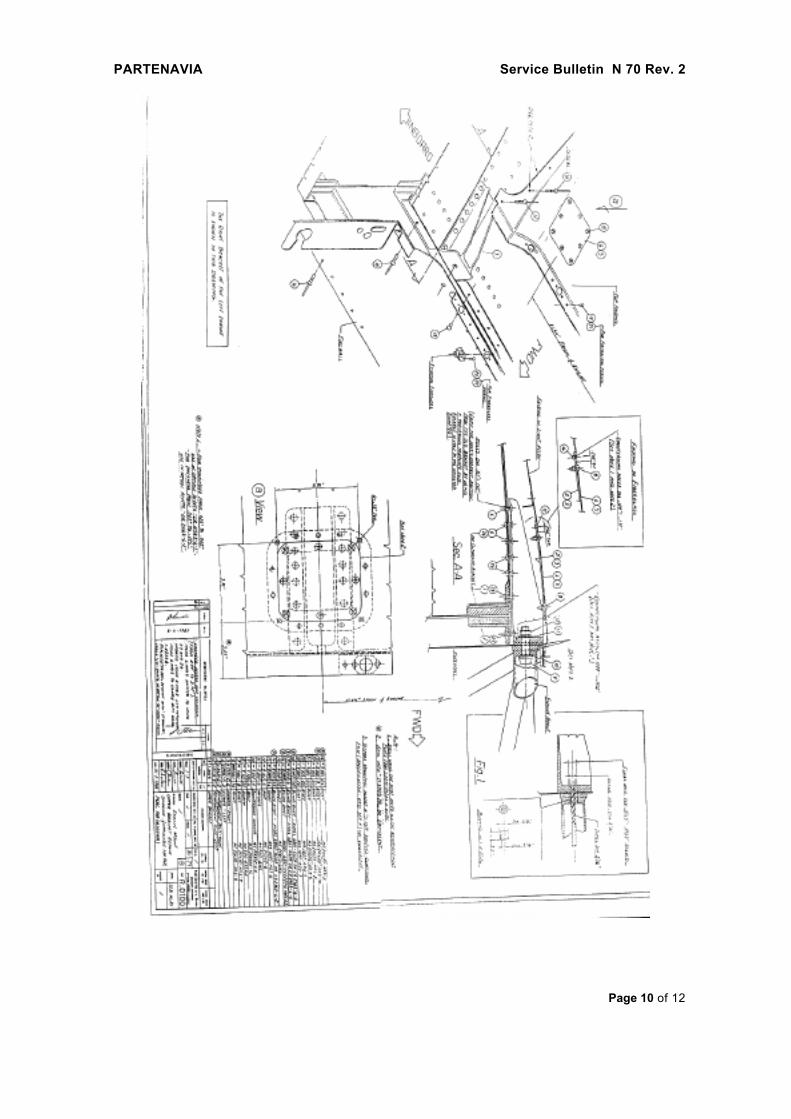
1-19) Carry out inspection holes on the fairing covering the upper brackets as shown in
draw. R.0100 (R.0102) view “a”;
1-20) Reinstall the engine mount as per step 2-18;
1-21) Reinstall the top fairing. To avoid water seepage into bracket housing, seal top fairing
using sealant type PR JR 5005 PR or equivalent. Cherry rivets to be used for fairing
installation are shown in draw. R.0100 (R.0102). For eventually enlarged holes use
immediately next diameter;
1-22) Reinstall the engine cowlings;
1-23) Perform an engine running and a systems check for correct operation;
WARNING
During engine test, perform a CROSSFEED test also.
1-24) Report on the Frame Log Book compliance with Section 1 of the present Service
Bulletin and the parts eventually replaced.
PARTENAVIA Service Bulletin N 70 Rev. 2
Page 6 of 12
SECTION 2
INSTRUCTION FOR REPLACEMENT
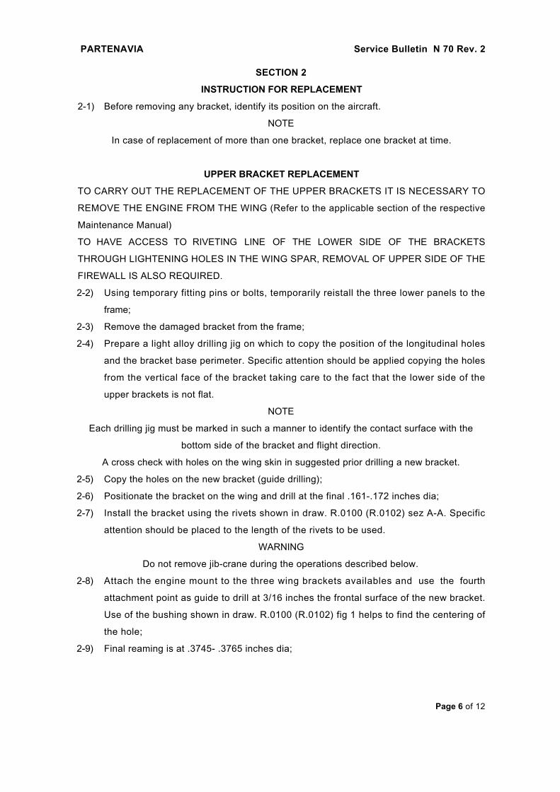
2-1) Before removing any bracket, identify its position on the aircraft.
NOTE
In case of replacement of more than one bracket, replace one bracket at time.
UPPER BRACKET REPLACEMENT
TO CARRY OUT THE REPLACEMENT OF THE UPPER BRACKETS IT IS NECESSARY TO
REMOVE THE ENGINE FROM THE WING (Refer to the applicable section of the respective
Maintenance Manual)
TO HAVE ACCESS TO RIVETING LINE OF THE LOWER SIDE OF THE BRACKETS
THROUGH LIGHTENING HOLES IN THE WING SPAR, REMOVAL OF UPPER SIDE OF THE
FIREWALL IS ALSO REQUIRED.
2-2) Using temporary fitting pins or bolts, temporarily reistall the three lower panels to the
frame;
2-3) Remove the damaged bracket from the frame;
2-4) Prepare a light alloy drilling jig on which to copy the position of the longitudinal holes
and the bracket base perimeter. Specific attention should be applied copying the holes
from the vertical face of the bracket taking care to the fact that the lower side of the
upper brackets is not flat.
NOTE
Each drilling jig must be marked in such a manner to identify the contact surface with the
bottom side of the bracket and flight direction.
A cross check with holes on the wing skin in suggested prior drilling a new bracket.
2-5) Copy the holes on the new bracket (guide drilling);
2-6) Positionate the bracket on the wing and drill at the final .161-.172 inches dia;
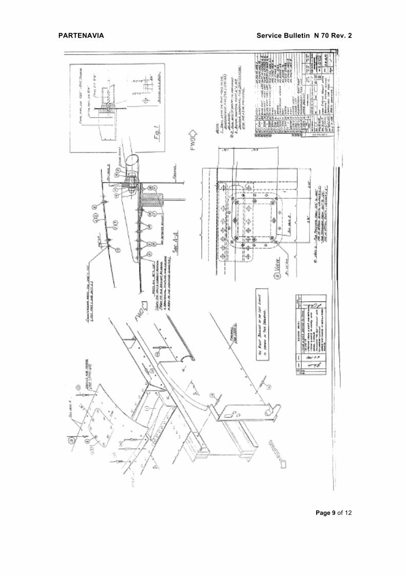
2-7) Install the bracket using the rivets shown in draw. R.0100 (R.0102) sez A-A. Specific
attention should be placed to the length of the rivets to be used.
WARNING
Do not remove jib-crane during the operations described below.
2-8) Attach the engine mount to the three wing brackets availables and use the fourth
attachment point as guide to drill at 3/16 inches the frontal surface of the new bracket.
Use of the bushing shown in draw. R.0100 (R.0102) fig 1 helps to find the centering of
the hole;
2-9) Final reaming is at .3745- .3765 inches dia;
PARTENAVIA Service Bulletin N 70 Rev. 2
Page 7 of 12
2-10) Treat bracket front surfaces with anticorrosive type S 15/9 (Spec DTD 369-A) or
equivalent;
2-11) Reinstall the firewall using rivets shown in draw R.0100 (R.0102);
NOTE
Do not fix the firewall to the bracket.
2-12) Reinstall the engine mount to the wing;
NOTES
Connection between engine mount and bracket is carried out by bolt and nuts as shown in
draw. R.0100 (R.0102) Section A-A;
The anchor nut installation holes in the firawall must be filled with sealant Spec DTD 369-A;
Imbibe the bolt in the anticorrosive, specified at step 2-10, before installation;
If a second upper bracket has to be replaced, repeat the procedures from step 2-3);
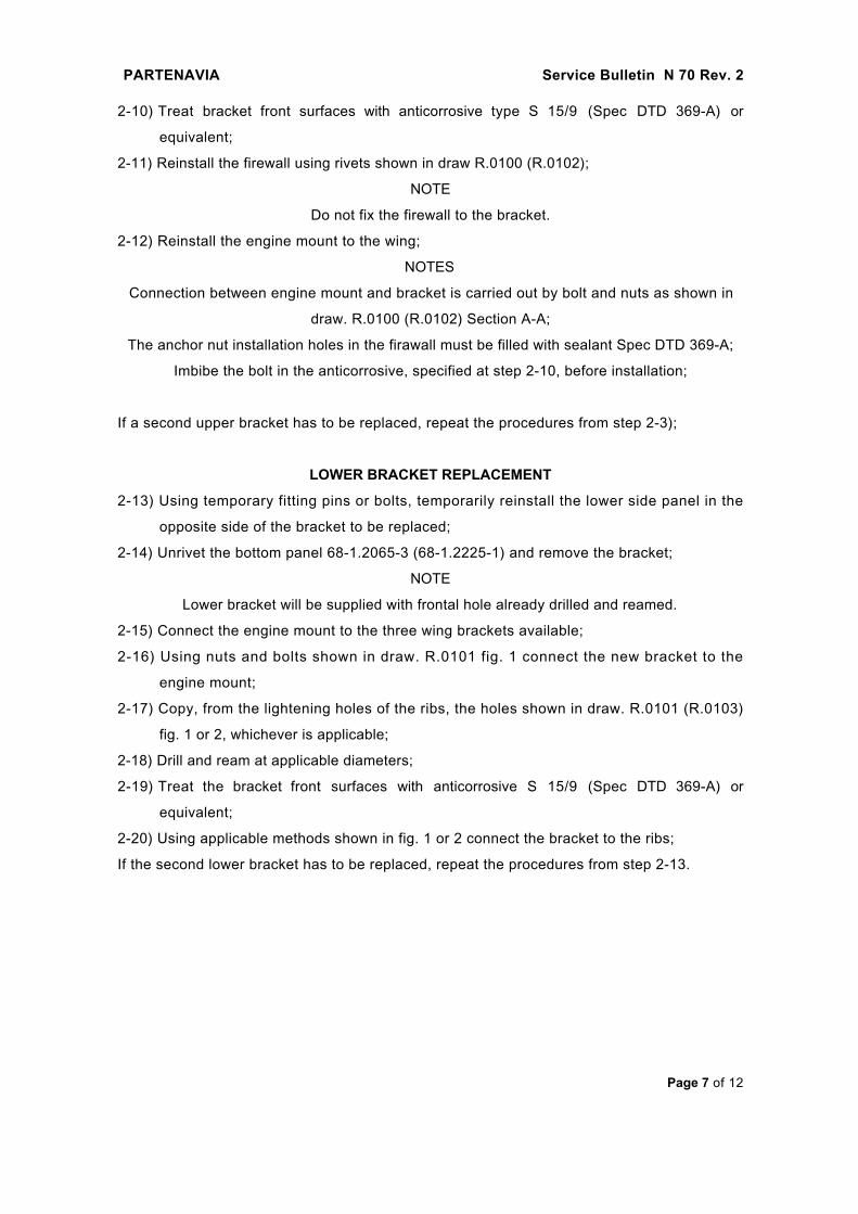
LOWER BRACKET REPLACEMENT
2-13) Using temporary fitting pins or bolts, temporarily reinstall the lower side panel in the
opposite side of the bracket to be replaced;
2-14) Unrivet the bottom panel 68-1.2065-3 (68-1.2225-1) and remove the bracket;
NOTE
Lower bracket will be supplied with frontal hole already drilled and reamed.
2-15) Connect the engine mount to the three wing brackets available;
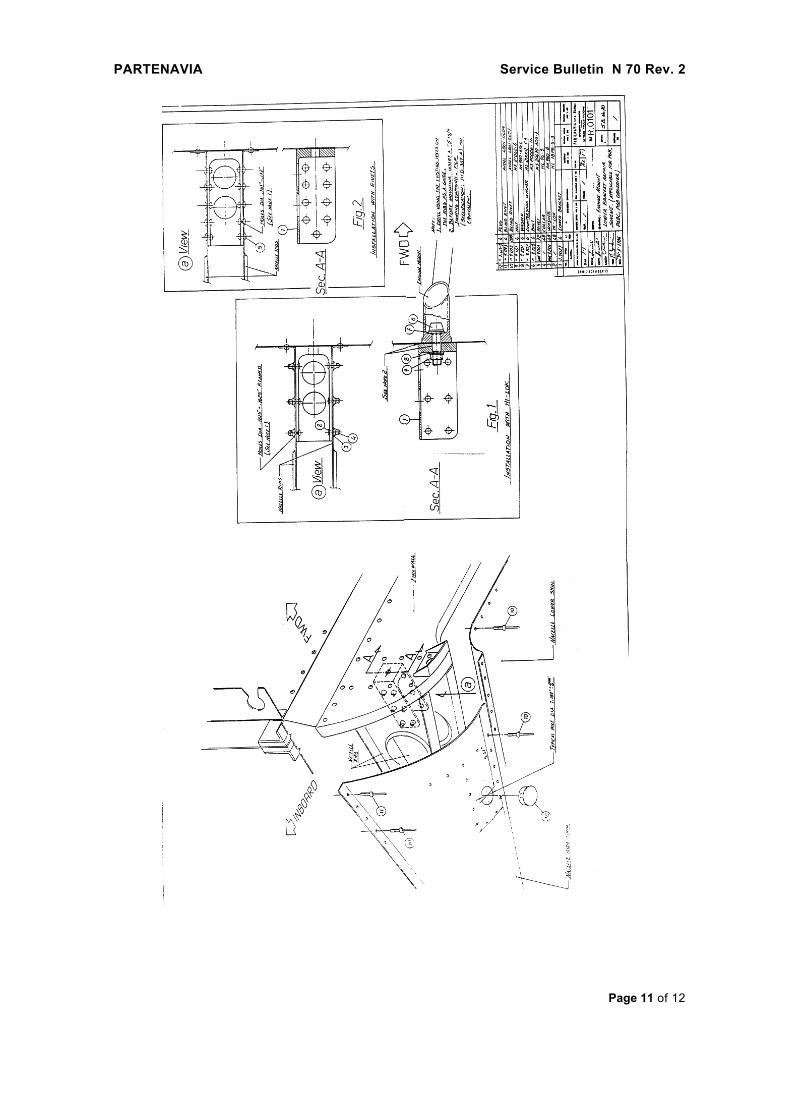
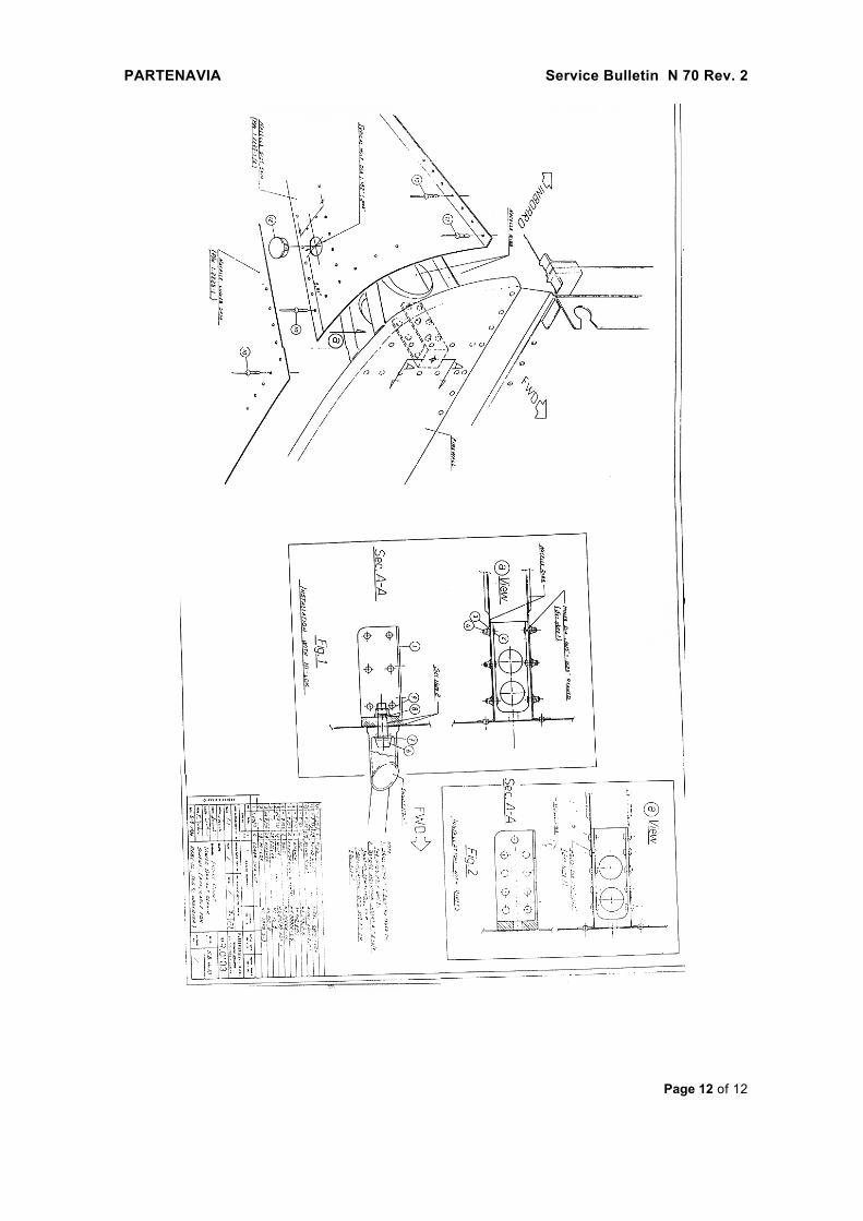
2-16) Using nuts and bolts shown in draw. R.0101 fig. 1 connect the new bracket to the
engine mount;
2-17) Copy, from the lightening holes of the ribs, the holes shown in draw. R.0101 (R.0103)
fig. 1 or 2, whichever is applicable;
2-18) Drill and ream at applicable diameters;
2-19) Treat the bracket front surfaces with anticorrosive S 15/9 (Spec DTD 369-A) or
equivalent;
2-20) Using applicable methods shown in fig. 1 or 2 connect the bracket to the ribs;
If the second lower bracket has to be replaced, repeat the procedures from step 2-13.
PARTENAVIA Service Bulletin N 70 Rev. 2
Page 8 of 12
SECTION 3
ROUTINE INSPECTION
3-1) Remove the caps from the bottom of the engine rear cowlings;
3-2) Remove the ispection panels from the top of the upper cowling;
3-3) Using light or boroscope inspect the brackets for absence of corrosion and cracks.
In case of doubt proceed in the inspection with a suitable method of investigation;
3-4) If defect is detected refer to the applicable section of this Service Bulletin;
3-5) Check datum points on anchor nuts and engine mount attachment bolts for integrity;
3-6) Report on the Frame Log Book compliance with Section 3 of the present Service
Bulletin.
SECTION 4
KITS RELEVANT TO THE SERVICE BULLETIN
SECTION 1 (Inspection)
P 68, P 68B, P 68C, P 68 Observer ………………………………………… 68-039/1A
P 68C-TC, P 68TC Observer …………………………………………………… 68-039/3A
SECTION 2 (Replacement)
All models ……………………………………………………………………………68-039/2A
PARTENAVIA Service Bulletin N 70 Rev. 2
Page 9 of 12
PARTENAVIA Service Bulletin N 70 Rev. 2
Page 10 of 12
PARTENAVIA Service Bulletin N 70 Rev. 2
Page 11 of 12
PARTENAVIA Service Bulletin N 70 Rev. 2
Page 12 of 12