Embed Size (px)
Citation preview
Form No. 81-466-061 Revised 2016-06-01 (1) MICO, Inc.
SWITCH ASSEMBLY INSTRUCTIONS(Refer to Figures 1 through 4)
1. Clean the pedal assembly and surrounding area of dirt and debris. Disconnect the two wire harnesses at the connectors and remove the pedal assembly from the machine. 2. The new switch assembly provided in the repair kit is shipped as shown in Figure 1 and requires installation of the blue wire and red wire contacts into the connector. Locate the MICO part number (07-910-011, 07-910-026, or 07-910-053) on the bottom of the pedal assembly. 3. If you are servicing 07-910-026 carefully remove the black PVC insulator tubing, see Figure 1, from the wire harness. 07-910-026 re-uses an existing split loom insulator tubing. NOTE: Be careful not to damage the wires while removing PVC tubing.
4. 07-910-026: Install the red wire contact into the center position of connector, see Figure 2. Push contact straight into connector grommet until a decisive click is felt. A slight tug will confirm that it is properly locking into place. 07-910-011, 07-910-053: Install the red wire contact into the outside position of connector, see Figure 3. Push contact straight into connector grommet until a decisive click is felt. A slight tug will confirm that it is properly locking into place.
5. 07-910-026: Install the blue wire contact into the outside position of connector, see Figure 2. Push contact straight into connector grommet until a decisive click is felt. A slight tug will confirm that it is properly locking into place. 07-910-011, 07-910-053: Install the blue wire contact into the center position of connector, see Figure 3. Push contact straight into connector grommet until a decisive click is felt. A slight tug will confirm that it is properly locking into place
6. Install the orange wedge into connector with the half holes aligning with the contacts, see Figure 4. Push on wedge until it snaps into place.
7. 07-910-026: Proceed to pages 2 and 3 to continue switch replacement instructions. 07-910-011, 07-910-053: Proceed to page 4 to continue switch replacement instructions.
ELECTRONICPEDAL
Service Instructions
NOTE These instructions are for replacing the snap-action switch assembly on MICO® Electronic Pedals, model numbers 07-910-011, 07-910-026, and 07-910-053.
For Model Number 07-910-026FIGURE 2
FIGURE 1
For Model Number 07-910-011, 07-910-053FIGURE 3
FIGURE 4

MICO, Inc. (2) Form No. 81-466-061 Revised 2016-06-01
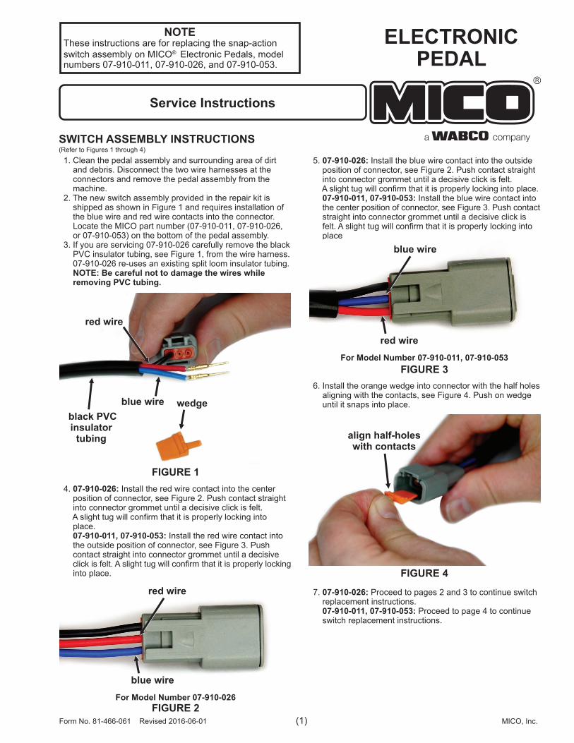
Model: 07-910-026DISASSEMBLY PROCEDURE(Refer to Figure 5)
1. Remove the split loom insulator tubing from the existing switch assembly (7) wire harness for re-use during assembly.
2. Remove three screws (2) and cover (3) from pedal assembly (1).
3. To provide the needed clearance to access screws (6), loosen hex nut (4) and adjust cap screw (5) and nut (4) into the position shown in Figure 5a.
4. Rotate pedal forward and remove two screws (6), switch assembly (7), two spacers (8), four washers (9) and two lock washers (10) from pedal assembly (1).
5. Loosen jam nut (12). Use a hex key wrench and remove plunger (13) from the bottom side of pedal.
6. Slide two rubber grommets (11) securing the harness wires from pedal assembly (1). Remove two rubber grommets (11) from the harness wires.
ASSEMBLY PROCEDURE (Refer to Figure 5)
1. It may be useful to position the pedal assembly (1) on a tabletop with cover (3) side facing downward. Apply one drop of Loctite to each of the threaded switch mounting screw holes on pedal assembly (1). Install two screws (6) through mounting holes on new switch assembly (7) and stack new spacers (8), new washers (9), new lock washers (10) and new washers (9) on the ends of new screws (6) in the order as shown in Figure 5. While holding these items in place, carefully install the two new screws (6) into the threaded holes on pedal assembly (1). Torque two new screws (6) 0.46-0.68 N·m (4-6 lb·in).
2. Guide the wires from the new switch assembly (7) and the wires from the pedal angle sensor through the new rubber grommets (11). Install two new grommets (11) into slots on pedal assembly (1).
3. Reinstall the split loom insulator tubing on new switch assembly (7) wire harness.
4. Install cover (3) and three screws (2) in pedal assembly (1). Torque three screws (2) 1.69-2.83 N·m (15-25 lb·in).
5. Clamp pedal assembly (1) in a bench vise. Clamp on the spring pack housing as shown in Figure 5a.
6. Install new jam nut (12) on new plunger (13). Thread new jam nut (12) onto new plunger (13) until jam nut touches the plastic boot on plunger.
7. Apply one drop of Loctite to the threads on new plunger (13). Install new plunger (13) from the bottom side of pedal. Screw plunger (13) into the pedal until the jam nut on plunger (13) is touching the back side of the pedal.
8. Fully depress pedal and use a large c-clamp to hold pedal in the fully depressed position.
9. Screw plunger (13) out of the bottom of pedal until the plunger (13) tip contacts and clicks the snap switch in new switch assembly (7). See Figures 5b & 5c. NOTE: Optimal switch/plunger adjustment is when the switch clicks on and off when the pedal position is as close to fully depressed as possible.
10. Use a hex key wrench to hold plunger (13) in position and torque hex nut (12) 0.46-0.68 N·m (4-6 lb·in), see Figure 5b. NOTE: Do not over tighten jam nut (12) or plunger (13) can be damaged.
11. Release the pedal from the c-clamp. Carefully depress the pedal several times to be sure the plunger is properly adjusted and can not damage the snap switch when the pedal is fully depressed.
12. Position pedal so cam is in contact with input piston, see Figure 5d. Properly readjust cap screw (5) by unscrewing the cap screw from pedal assembly (1) until cap screw head contacts the bottom of the pedal.
13. Remove the pedal assembly (1) from bench vise. Reinstall pedal assembly on machine according to machine service manual. Reattach the wire harness connectors. Be sure the pedal is functioning properly before using machine.
Form No. 81-466-061 Revised 2016-06-01 (3) MICO, Inc.
Items included in Repair Kit 07-400-006
FIGURE 5a
FIGURE 5
FIGURE 5c
FIGURE 5d
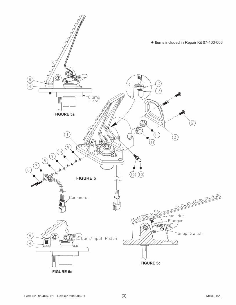
Models: 07-910-011 07-910-053
DISASSEMBLY PROCEDURE (Refer to Figure 6)
1. Clamp pedal assembly (1) in a bench vise. Clamp on the spring pack housing as shown in Figure 6a. Fully depress pedal and use a large c-clamp to hold pedal in the fully depressed position.
2. Remove switch assembly (5) from pedal assembly (1) by removing two nuts (7), two lock washers (5) and two screws (4).
3. Remove jam nut (2). Use a hex key wrench and remove plunger (3) from the bottom side of pedal.
ASSEMBLY PROCEDURE (Refer to Figure 6)
1. Apply one drop of Loctite to the threads of new plunger (3). Install new plunger (3) from the back side of the pedal. Screw plunger (3) into the pedal until the plastic boot contacts the pedal.
2. Before placing new switch (5) into position for assembly, install two new screws (4) through the switch mounting holes. Install new switch (5) and new screws (4) on the mounting bracket. Install two new washers (6) on screws (4).
3. Apply one drop of Loctite to the ends of threads of new screws (4). Install new nut (7) on new screws (4) and torque 0.46-0.68 N·m (4-6 lb·in).
4. Screw plunger (3) out of the back side of pedal until the plunger (3) tip contacts and clicks the snap switch in new switch assembly (5).
07-910-011: Remove c-clamp and allow pedal to return to full released position. Use a hex key wrench to hold plunger (3) in position and install new jam nut (2). Torque jam nut (2) 0.46-0.68 N·m (4-6 lb·in). See Figures 6 and 6a. NOTE: Do not over tighten jam nut (2) or plunger (3) can be damaged. Optimal switch/plunger adjustment is when the switch clicks on and off when the pedal position is as close to fully depressed as possible. 07-910-053: Remove c-clamp to allow pedal to return to the neutral position before setting switch. Use a hex key wrench to hold plunger (3) in position and install new jam nut (2). Torque jam nut (2) 0.46-0.68 N·m (4-6 lb·in). See Figures 6 and 6a. NOTE: Do not over tighten jam nut (2) or plunger (3) can be damaged. Optimal plunger adjustment is when switch clicks on and off when pedal leaves neutral (unapplied) position.
5. Carefully depress the pedal several times to be sure the plunger is properly adjusted and can not damage the snap switch when the pedal is fully depressed.
6. Remove pedal assembly (1) from bench vise. Reinstall pedal assembly on machine according to machine service manual. Reattach the wire harness connectors. Be sure the pedal is functioning properly before using machine.
This document is intended to provide general information about MICO Products. MICO, Inc. has attempted to present accurate information about MICO Products in its catalogs, brochures, and other printed materials. MICO, Inc. is not responsible for errors, inaccuracies, or inconsistencies that may exist in any catalog, brochure, or other printed materials or any damages arising from or related to reliance on information in them. Materials and specifications for MICO Products set forth in catalogs, brochures, and other printed materials are subject to change without notice or obligation. Refer to www.mico.com for the most recent versions of our literature. If you have any questions concerning MICO Products, please contact MICO, Inc. All MICO Products and service are sold and provided subject to the MICO Warranty at www.mico.com in effect on the date of sale or supply.
MICO is a trademark and registered trademark of MICO, Inc. MICO is registered in the U.S. Patent and Trademark Office as well as in Australia, Canada, Indonesia, Japan, Peoples Republic of China, South Korea, and the European Community.
MICO, Inc.1911 Lee Boulevard / North Mankato, MN U.S.A. 56003-2507 Tel: +1 507 625 6426 Fax: +1 507 625 3212
Form No. 81-466-061 Revised 2016-06-001 www.mico.com
FIGURE 6
Items included in Repair Kit 07-400-006
FIGURE 6a