Embed Size (px)
Citation preview

SERVICE LIFE OF HIGHLY FLEXIBLE COUPLINGS

03 THEORETICAL EXPECTED LIFETIME
04 PERMISSIBLE PERMANENT SET
04 RATO S
04 RATO S+
05 RATO R
05 RATO R+
05 VULKARDAN E
05 VULKARDAN F
05 VULKARDAN G
05 VULKARDAN L
06 RATO DS
06 RATO DS+
06 RATO DG
06 RATO DG+
07 VULASTIK L
08 PERMISSIBLE DEPTHS OF CRACKS
08 RATO S
09 RATO S+
10 RATO R
11 RATO R+
12 VULKARDAN E
12 VULKARDAN F
12 VULKARDAN G
12 VULKARDAN L
13 RATO DS
13 RATO DS+
14 RATO DG
14 RATO DG+
15 VALIDITY CLAUSE
Contents
03SERVICE LIFE OF HIGHLY FLEXIBLE COUPLINGS
Tearing
>10
YEARS SERVICE LIFE
OPERATIO
N HOURS
VULKAN couplings are produced and tested under the most stringent quality
controls. In this way, apart from a high level of functional safety across several
hours of operation, they even offer the user a long service life of several years.
The expected service life of the flexible elements is depending on the individual
operating or storage conditions.
Even under best conditions a significant excess of time periods (of service life
or hours of operation) may lead to changes in the dynamic characteristics or
functional performance of the coupling. Impermissible or excessively high
element stresses caused by the connected machinery reduce the expected
service life.
Hence, we recommend that you regularly inspect the elements at least twice
a year. The inspection procedure should consider both the service life and the
operating hours. The operating hour inspection can be done by checking the
permanent set and the surface for cracks. This inspection can be completed
on-site by referring to the data on the attached tables.
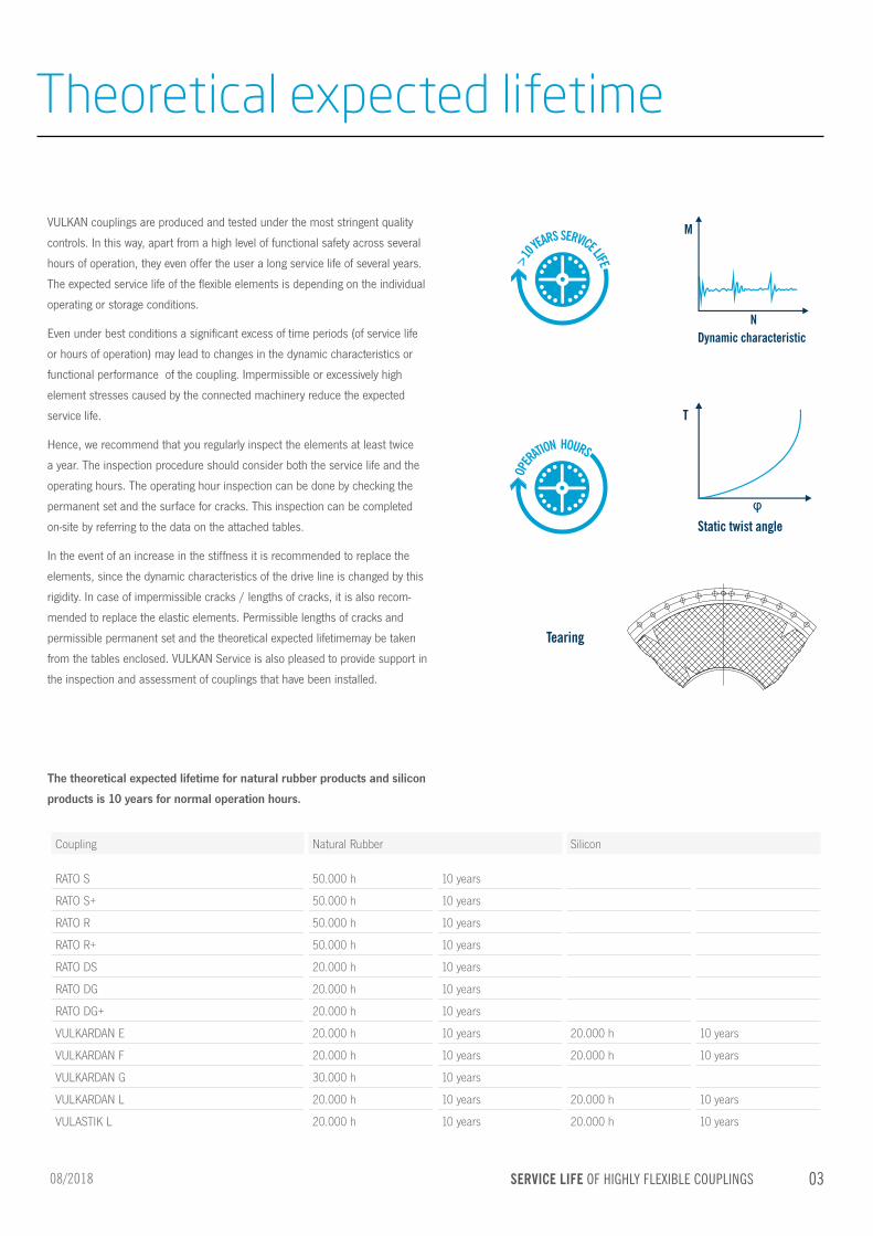
In the event of an increase in the stiffness it is recommended to replace the
elements, since the dynamic characteristics of the drive line is changed by this
rigidity. In case of impermissible cracks / lengths of cracks, it is also recom-
mended to replace the elastic elements. Permissible lengths of cracks and
permissible permanent set and the theoretical expected lifetimemay be taken
from the tables enclosed. VULKAN Service is also pleased to provide support in
the inspection and assessment of couplings that have been installed.
The theoretical expected lifetime for natural rubber products and silicon
products is 10 years for normal operation hours.
Theoretical expected lifetime
Coupling Natural Rubber Silicon
RATO S 50.000 h 10 years
RATO S+ 50.000 h 10 years
RATO R 50.000 h 10 years
RATO R+ 50.000 h 10 years
RATO DS 20.000 h 10 years
RATO DG 20.000 h 10 years
RATO DG+ 20.000 h 10 years
VULKARDAN E 20.000 h 10 years 20.000 h 10 years
VULKARDAN F 20.000 h 10 years 20.000 h 10 years
VULKARDAN G 30.000 h 10 years
VULKARDAN L 20.000 h 10 years 20.000 h 10 years
VULASTIK L 20.000 h 10 years 20.000 h 10 years
08/2018

04 SERVICE LIFE OF HIGHLY FLEXIBLE COUPLINGS
FIGURE 1
FIGURE 2
FIGURE 3
Checking the permissible permanent set of a RATO S / RATO S+ segment takes place by obtaining „S“ at the outer diameter of the rubber element (Figure 1). In case of a RATO R / RATO R+ / VULKARDAN E / VULKARDAN F / VULKARDAN G / VULKARDAN L element, the dimension „S“ may be obtained from the deformation of the rubber beading (Figure 3).
RATO SPermissible permanent setRATO S / RATO S+ / RATO R / RATO R+ / VULKARDAN E / F / G / L
Size S [mm]
G 0310 55.0
G 0510 65.0
G 0810 78.0
G 1210 20.0
G 1310 20.0
G 1410 22.0
G 1510 23.0
G 1610 25.0
G 1710 27.0
G 1910 29.0
G 2110 31.0
G 2310 33.0
G 2510 36.0
G 2710 36.0
G 2910 40.0
G 3010 45.0
G 3110 45.0
G 3210 48.0
G 3310 48.0
G 3410 51.0
G 3510 51.0
G 3610 58.0
G 3710 58.0
G 3810 92.0
G 3910 60.0
G 4010 60.0
G 4310 64.0
G 4410 64.0
G 4510 110.0
G 4610 38.0
G 4710 80.0
G 4810 80.0
G 4910 38.0
G 5010 85.0
G 5110 85.0
G 5310 130.0
G 5410 40.0
G 5510 90.0
G 5610 90.0
G 5720 97.0
G 5810 98.0
G 6010 44.0
G 6210 100.0
G 6310 100.0
G 6510 44.0
G 6810 118.0
G 7010 44.0
G 7310 125.0
RATO S+
Size S [mm]
G 4J10 80.0
G 5B10 85.0
G 5G10 90.0
G 5H20 98.0
S
S
08/2018
PERMISSIBLE PERMANENT SET OF RATO S / RATO S+ / RATO R / RATO R+ / VULKARDAN E / F / G / L

05SERVICE LIFE OF HIGHLY FLEXIBLE COUPLINGS
VULKARDAN E
VULKARDAN F
Size S [mm]
E 1710 14.0
E 2310 22.0
E 2410 17.0
E 2810 20.0
E 3210 25.0
E 3410 33.0
E 4010 34.0
E 4910 39.0
E 5410 51.0
E 5710 48.0
E 6010 60.0
Size S [mm]
F 3510 25.0
F 4210 34.0
F 5010 39.0
F 5410 51.0
F 5710 48.0
F 6010 60.0
F 6210 60.0
VULKARDAN G
Size S [mm]
G 5410 16.0
G 5710 16.0
G 6010 20.0
G 6210 24.0
G 8410 17.0
VULKARDAN L
Size S [mm]
L 1710 14.0
L 1910 15.0
L 2110 16.0
L 2510 18.0
L 2910 21.0
L 3410 32.0
L 4110 34.0
L 4510 35.0
L 4810 37.0
L 5010 39.0
L 5810 49.0
* Values for 3-row elements
RATO R
Size S [mm]
G 1610R 26.0
G 1710R 28.0
G 1910R 29.0
G 2110R 33.0
G 2310R 35.0
G 2410R 19.0
G 2510R 39.0
G 2610R 42.0
G 2710R 42.0
G 2730R* 27.0
G 2910R 44.0
G 2930R* 29.0
G 3110R 50.0
G 3210R 58.0
G 3310R 58.0
G 3330R* 35.0
G 3430R* 37.0
G 3510R 37.0
G 3810R 44.0
G 3910R 75.0
G 4010R 75.0
G 4710R 75.0
* Values for 3-row elements
RATO R +
Size S [mm]
G 2D10 35.0
G 2F10 39.0
G 2G10 42.0
G 3B10 50.0
G 3C10 58.0
G 3E30* 37.0
G 4A10 75.0
08/2018
PERMISSIBLE PERMANENT SET OF RATO S / RATO S+ / RATO R / RATO R+ / VULKARDAN E / F / G / L

06 SERVICE LIFE OF HIGHLY FLEXIBLE COUPLINGS
FIGURE 1 – RATO DS
FIGURE 2 – RATO DG / RATO DG+
Checking the permissible permanent set of a RATO DS / RATO DG element takes place by obtaining „S“ at the outer diameter of the rubber element (Figures 1 & 2).
Permissible permanent setRATO DS / RATO DS+ / RATO DG / RATO DG+ RATO DS
Size S [mm]
2110 48
2310 52
2510 56
2710 61
2910 66
3110 70
3310 76
3410 82
3910 88
RATO DS+
Size S [mm]
2K10 66
3D10 70
RATO DG
Size S [mm]
2110 20
2310 24
2510 24
2710 27
2910 30
3110 31
3310 34
3410 36
3610 403910 42
RATO DG+
Size S [mm]
2K10 30
3D10 34
S
0
0O
S
0
0
O
08/2018
PERMISSIBLE PERMANENT SET OF RATO DS / RATO DS+ /RATO DG / RATO DG+

07SERVICE LIFE OF HIGHLY FLEXIBLE COUPLINGS
FIGURE 3
Due to different inner design and multiple rubber stiffness of the Vulastik L the permanent set is depending on stiffness. The parameter for the per-missible permanent set is the dimension „b“. The permissible permanent set „b“ is determined by the distance between the positions A and B.Position A lies on the extension of both the threaded boreholes of the angular ring. Position B is identified by the marking on the element. During operation, the element deforms itself and the marking shifts in the direction of rotation from the position A to the position B.
Permissible permanent setVULASTIK L VULASTIK L
Rubber quality
Size 4 1 2 3 6 8 A S Reference diameter
141X 24 18 16 16 16 16 16 22 Ø 203
161X 35 28 18 18 18 18 18 24 Ø 252
191X 36 29 19 19 19 19 19 24 Ø 288
221X 44 35 22 22 22 22 22 30 Ø 342
261X 48 38 25 25 25 25 25 32 Ø 390
301X 47 37 26 26 26 20 20 32 Ø 390
321X 47 37 26 26 26 26 26 32 Ø 390
331X 46 36 24 24 24 24 24 31 Ø 390
341X 39 30 21 21 21 21 21 30 Ø 450
371X 40 31 22 22 22 22 22 31 Ø 450
401X 46 35 24 24 24 24 24 44 Ø 531
431X 46 35 24 24 24 24 24 44 Ø 531
b in mm
threadholes
Marker for permanent deformationafter a period of use
Outer surface at beginning
Marker for permanent deformationat beginning
Outer surfaceafter use
R5
b
Ød ref
08/2018
PERMISSIBLE PERMANENT SET OF VULASTIK L

08 SERVICE LIFE OF HIGHLY FLEXIBLE COUPLINGS
As a result of the deformation of the elastic part during operation, cracks may get formed that are permissible up to a limited depth (Figures 1 & 2). Based on our experience, you may consider surface cracks in the elastic part of a RATO S / S+ / R coupling permissible, if these cracks occur on all sides of the entire surface up to a depth as mentioned (Figure 1, depth X). With cracks predominantly in the outer rubber corner surface, including the radius area, an equivalent depth of crack as mentioned (Figure 2, depth Y,Z). The following values are related to rubber as the material. If the permissible depth of a crack is exceeded, it is recommended to replace the element / segment concerned as soon as possible.
Permissible depths of cracks RATO S RATO S
Depth
Size X [mm] Y [mm] Z [mm]
G 0310 8.0 13.0 42.0G 0510 10.0 14.0 49.0G 0810 10.0 19.0 57.0G 1210 4.3 7.0 19.0G 1310 4.7 7.0 21.0G 1410 5.0 8.0 22.0G 1510 5.5 8.0 24.0G 1610 6.0 9.0 26.0G 1710 6.5 9.0 28.0G 1910 7.0 10.0 30.0G 2110 7.0 10.0 33.0G 2310 8.0 13.5 36.0G 2510 9.0 15.5 38.0G 2710 9.5 16.0 42.0G 2910 10.0 17.0 45.0G 3010 11.0 19.0 49.0G 3110 11.0 19.0 49.0G 3210 12.0 20.5 52.0G 3310 12.0 20.5 52.0G 3410 13.0 22.0 57.0G 3510 13.0 22.0 57.0G 3610 13.0 24.0 61.0G 3710 13.0 24.0 61.0G 3810 15.0 25.5 66.0G 3910 15.0 25.5 66.0G 4010 15.0 25.5 66.0G 4310 15.0 27.0 71.0G 4410 15.0 27.0 71.0G 4510 15.0 30.5 77.0G 4610 15.0 30.5 77.0G 4710 15.0 30.5 77.0G 4810 15.0 30.5 77.0G 4910 18.0 32.5 83.0G 5010 18.0 32.5 83.0G 5110 18.0 32.5 83.0G 5310 20.0 34.0 90.0G 5410 20.0 34.0 90.0G 5510 20.0 34.0 90.0G 5610 20.0 34.0 90.0G 5720 21.0 36.0 94.0G 5810 20.0 37.5 97.0G 6010 20.0 37.5 97.0G 6210 20.0 39.0 103.0G 6310 20.0 39.0 103.0G 6510 20.0 41.0 105.0G 6810 20.0 42.5 111.0G 7010 20.0 42.5 113.0G 7310 20.0 47.5 125.0
FIGURE 1
FIGURE 2
X
X
Y
Z
Y
08/2018
PERMISSIBLE DEPTHS OF CRACKSOF RATO S

09SERVICE LIFE OF HIGHLY FLEXIBLE COUPLINGS
FIGURE 1
FIGURE 2
As a result of the deformation of the elastic part during operation, cracks may get formed that are permissible up to a limited depth (Figures 1 & 2). Based on our experience, you may consider surface cracks in the elastic part of a RATO S / S+ / R coupling permissible, if these cracks occur on all sides of the entire surface up to a depth as mentioned (Figure 1, depth X). With cracks predominantly in the outer rubber corner surface, including the radius area, an equivalent depth of crack as mentioned (Figure 2, depth Y,Z). The following values are related to rubber as the material. If the permissible depth of a crack is exceeded, it is recommended to replace the element / segment concerned as soon as possible.
Permissible depths of cracks RATO S+ RATO S+
Depth
Size X [mm] Y [mm] Z [mm]
G 4J10 15.0 30.5 77.0G 5B10 18.0 32.5 83.0G 5G10 18.0 34.0 90.0G 5H20 18.0 36.0 94.0
X
X
Y
Z
Y
08/2018
PERMISSIBLE DEPTHS OF CRACKSOF RATO S+

10 SERVICE LIFE OF THE COUPLINGS
Permissible depths of cracks RATO R
FIGURE 1
As a result of the deformation of the elastic part during operation, cracks may get formed that are permissible up to a limited depth (Figures 1 & 2). Based on our experience, you may consider surface cracks in the elastic part of a RATO S / S+ / R coupling permissible, if these cracks occur on all sides of the entire surface up to a depth as mentioned (Figure 1, depth X). With cracks predominantly in the outer rubber corner surface, including the radius area, an equivalent depth of crack as mentioned (Figure 2, depth Y,Z). The following values are related to rubber as the material. If the permissible depth of a crack is exceeded, it is recommended to replace the element / segment concerned as soon as possible.
RATO R
Depth
Size X [mm] Y* [mm]
G 1610R 6.0 10.0G 1710R 6.5 10.0G 1910R 7.0 10.0G 2110R 7.0 10.0G 2310R 8.0 10.0G 2410R 8.0 10.0G 2510R 8.0 10.0G 2610R 8.0 12.0G 2710R 8.0 12.0G 2730R 8.0 12.0G 2910R 10.0 12.0G 2930R 10.0 12.0G 3110R 10.0 15.0G 3210R 10.0 15.0G 3310R 10.0 15.0G 3330R 10.0 15.0G 3430R 12.0 15.0G 3510R 12.0 15.0G 3810R 15.0 18.0G 3910R 15.0 18.0G 4010R 15.0 18.0G 4710R 15.0 18.0
* Cracks in the outer diameter area / inner diameter is free of cracks
Y X
X
02/2016
PERMISSIBLE DEPTHS OF CRACKSOF RATO R

11SERVICE LIFE OF THE COUPLINGS
RATO R+
Depth
Size X [mm] Y* [mm]
G 2D10R 8.0 13.6G 2F10R 8.0 14.6G 2G10R 8.0 15.8G 3B10R 10.0 18.5G 3C10R 10.0 20.1G 3E30R 10.0 22.7G 4A10R 15.0 25.6
* Cracks in the outer diameter area / inner diameter is free of cracks
Permissible depths of cracks RATO R+
FIGURE 1
As a result of the deformation of the elastic part during operation, cracks may get formed that are permissible up to a limited depth (Figures 1 & 2). Based on our experience, you may consider surface cracks in the elastic part of a RATO S / S+ / R coupling permissible, if these cracks occur on all sides of the entire surface up to a depth as mentioned (Figure 1, depth X). With cracks predominantly in the outer rubber corner surface, including the radius area, an equivalent depth of crack as mentioned (Figure 2, depth Y,Z). The following values are related to rubber as the material. If the permissible depth of a crack is exceeded, it is recommended to replace the element / segment concerned as soon as possible.
Y X
X
02/2016
PERMISSIBLE DEPTHS OF CRACKSOF RATO R+

12 SERVICE LIFE OF THE COUPLINGS 02/2016
VULKARDAN E
Depth
Size X [mm] Y [mm]
E 1710 0.8 1.3E 2310 2.6 4.4E 2410 2.8 4.8E 2810 3.3 5.5E 3210 3.2 5.5E 3410 3.0 5.2E 4010 3.1 5.2E 4910 3.1 5.3E 5410 2.6 4.5E 5710 3.8 6.4E 6010 4.7 8.0
Depth
Size X [mm] Y [mm]
F 3510 3.2 5.5F 4210 3.1 5.2F 5010 3.1 5.3F 5410 2.6 4.5F 5710 3.8 6.4F 6010 4.7 8.0F 6210 4.7 8.0
VULKARDAN F
VULKARDAN G
Depth
Size X [mm] Y [mm]
G 5410 3.4 5.8G 5710 4.8 8.2G 6010 4.7 8.0G 6210 7.9 13.5G 8410 4.5 7.7
VULKARDAN L
Depth
Size X [mm] Y [mm]
L 1710 0.8 1.3L 1910 0.9 1.5L 2110 1.1 1.9L 2510 1.4 2.3L 2910 1.5 2.5L 3410 1.7 2.9L 4110 1.8 3.1L 4510 1.9 3.2L 4810 2.6 4.3L 5010 2.3 3.8L 5810 5.0 8.5
PERMISSIBLE DEPTHS OF CRACKSOF VULKARDAN E / VULKARDAN F / VULKARDAN G / VULKARDAN L

13SERVICE LIFE OF THE COUPLINGS02/2016
Based on our experience, you may consider surface cracks in an elastic part of a RATO DS / RATO DS+ coupling permissible if these cracks occur on all sides of the entire surface, up to a depth as given in the following table.
Permissible depths of cracks RATO DS / RATO DS+
FIGURE 1
FIGURE 2
RATO DS
* Table values: applicable, for cracks predominantly on one surface, with cracks uniformly on both surfaces, the value needs to be halved.
Depth*Cracks on
one surface
Depth*Cracks on
two surfaces
Size [mm] [mm]
21 12.0 6.023 13.5 6.725 15.5 7.727 16.0 8.029 15.0 8.031 15.0 9.033 20.0 10.034 20.0 10.039 20.0 12.0
RATO DS+
* Table values: applicable, for cracks predominantly on one surface, with cracks uniformly on both surfaces, the value needs to be halved.
Depth*Cracks on
one surface
Depth*Cracks on
two surfaces
Size [mm] [mm]
2K10 15.0 8.03D10 20.0 10.0
X
PERMISSIBLE DEPTHS OF CRACKSOF RATO DS / RATO DS+
Y
Y

14 SERVICE LIFE OF THE COUPLINGS 02/2016
Based on our experience, you may consider surface cracks in an elastic part of a RATO DG / DG+ coupling permissible if these cracks occur on all sides of the entire surface, up to a depth as given in the following table.
Permissible depths of cracks RATO DG / RATO DG+
FIGURE 1
FIGURE 2
Depth*Cracks on
one surface
Depth*Cracks on
two surfaces
Size [mm] [mm]
21 12.0 6.023 13.5 6.725 15.5 7.727 16.0 8.029 15.0 8.031 15.0 9.033 20.0 10.034 20.0 10.039 20.0 12.0
RATO DG
Depth*Cracks on
one surface
Depth*Cracks on
two surfaces
Size [mm] [mm]
2K10 15.0 8.03D10 20.0 10.0
* Table values: applicable, for cracks predominantly on one surface, with cracks uniformly on both surfaces, the value needs to be halved.
RATO DG+
PERMISSIBLE DEPTHS OF CRACKSOF RATO DG / RATO DG+
X
YY

15SERVICE LIFE OF THE COUPLINGS
VULKAN torsional vibration analysis usually only consider the pure mechanical
mass-elastic system. Being a component manufacturer exclusively, VULKAN
assumes no system responsibility with the analysis of the torsional vibration system
(stationary, transiently)! The accuracy of the analysis depends on the exactness of
the used data and the data VULKAN is provided with, respectively.
Any changes due to the technological progress are reserved. For questions or
queries please contact VULKAN.
Status: 08/2018
All duplication, reprinting and translation rights are reserved.
We reserve the right to modify dimensions and constructions without prior notice.
VALIDITY CLAUSE
The present brochure shall replace all previous editions, any previous printings
shall no longer be valid. Based on new developments, VULKAN reserves the right to
amend and change any details contained in this brochure respectively. The new data
shall only apply with respect to couplings that were ordered after said amendment
or change. It shall be the responsibility of the user to ensure that only the latest
brochure issue will be used. The respective latest issue can be seen on the website
of VULKAN on www.vulkan.com.
The data contained in this brochure refer to the technical standard as presently
used by VULKAN with defined conditions according to the explanations. It shall be
the sole responsibility and decision of the system administrator for the drive line to
draw conclusions about the system behaviour.
02/2016

Head Office: VULKAN Kupplungs- und Getriebebau Bernhard Hackforth GmbH & Co. KG | Heerstraße 66 | 44653 Herne | GermanyPhone + 49 (0) 2325 922-0 | Fax + 49 (0) 2325 71110 | Mail [email protected]
www.vulkan.com