Embed Size (px)
Citation preview
1998 Lennox Industries Inc.Litho U.S.A.
Page 1
Corp. 9822-L12
LGA/LCA
Service Literature3.0 to 6.0 TON10.5 to 21 kWRevised 09/2001
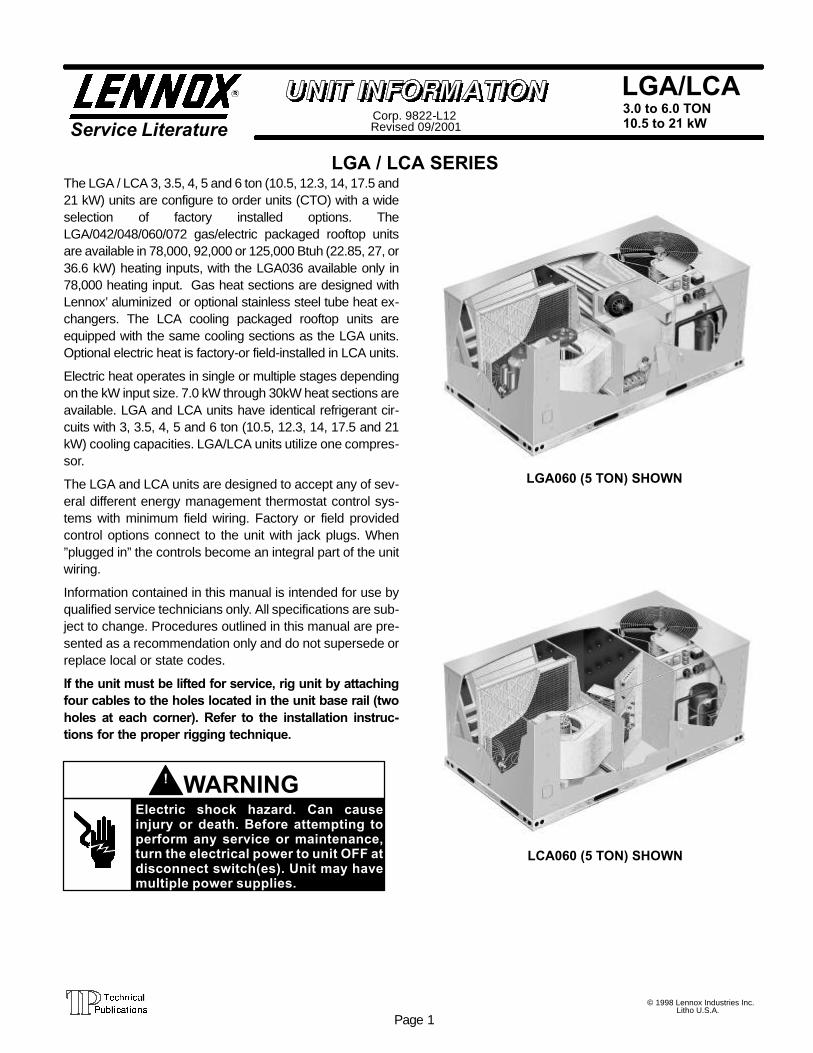
LGA / LCA SERIESThe LGA / LCA 3, 3.5, 4, 5 and 6 ton (10.5, 12.3, 14, 17.5 and21 kW) units are configure to order units (CTO) with a wideselection of factory installed options. TheLGA/042/048/060/072 gas/electric packaged rooftop unitsare available in 78,000, 92,000 or 125,000 Btuh (22.85, 27, or36.6 kW) heating inputs, with the LGA036 available only in78,000 heating input. Gas heat sections are designed withLennox’ aluminized or optional stainless steel tube heat ex-changers. The LCA cooling packaged rooftop units areequipped with the same cooling sections as the LGA units.Optional electric heat is factory-or field-installed in LCA units.
Electric heat operates in single or multiple stages dependingon the kW input size. 7.0 kW through 30kW heat sections areavailable. LGA and LCA units have identical refrigerant cir-cuits with 3, 3.5, 4, 5 and 6 ton (10.5, 12.3, 14, 17.5 and 21kW) cooling capacities. LGA/LCA units utilize one compres-sor.
The LGA and LCA units are designed to accept any of sev-eral different energy management thermostat control sys-tems with minimum field wiring. Factory or field providedcontrol options connect to the unit with jack plugs. When”plugged in” the controls become an integral part of the unitwiring.
Information contained in this manual is intended for use byqualified service technicians only. All specifications are sub-ject to change. Procedures outlined in this manual are pre-sented as a recommendation only and do not supersede orreplace local or state codes.
If the unit must be lifted for service, rig unit by attachingfour cables to the holes located in the unit base rail (twoholes at each corner). Refer to the installation instruc-tions for the proper rigging technique.
Electric shock hazard. Can causeinjury or death. Before attempting toperform any service or maintenance,turn the electrical power to unit OFF atdisconnect switch(es). Unit may havemultiple power supplies.
WARNING!
LGA060 (5 TON) SHOWN
LCA060 (5 TON) SHOWN
Page 2
TABLE OF CONTENTS
Introduction Page 1. . . . . . . . . . . . . . . . . . . . . . . . . . .Specifications Pages 3-4. . . . . . . . . . . . . . . . . . . . . .Electrical Data Pages 5-7. . . . . . . . . . . . . . . . . . . . . .Electrical Heat Accessories Data Page 8. . . . . . . . .Blower Data Pages 9-11. . . . . . . . . . . . . . . . . . . . . . .Parts Arrangement Page 12. . . . . . . . . . . . . . . . . . . .
I- UNIT COMPONENTS Pages 14-32. . . . . . . . . . . . .Control Box Components Pages 14-16. . . . . . . . . .Cooling Components Pages 17-19. . . . . . . . . . . . . .Blower Compartment Pages 19-22. . . . . . . . . . . . . .Gas Heat Components Pages 23-27. . . . . . . . . . . .Electric Heat Data Pages 28-30. . . . . . . . . . . . . . . . .Electric Heat Components Pages 31-32. . . . . . . . . .
II- PLACEMENT AND INSTALLATION Page 33. . . . .
III- CHARGING Pages 33-34. . . . . . . . . . . . . . . . . . . . .Normal Operating Pressures Pages 33-34. . . . . . .
IV-STARTUP - OPERATION Page 35-36. . . . . . . . . . . .Preliminary and Seasonal Checks Page 35. . . . . . .Cooling Startup Page 35. . . . . . . . . . . . . . . . . . . . . . .Heating Startup Page 36-37. . . . . . . . . . . . . . . . . . . .Safety or Emergency Shutdown Page 37. . . . . . .
V- SYSTEMS SERVICE CHECKS Pages 37-40. . . . .LGA Heating Service Checks Pages 37-40. . . . . . .High Altitude Page 38. . . . . . . . . . . . . . . . . . . . . . . . .Cooling Service Checks Page 40. . . . . . . . . . . . . . .
VI-MAINTENANCE Pages 40. . . . . . . . . . . . . . . . . . . . . .Filters Page 40. . . . . . . . . . . . . . . . . . . . . . . . . . . . . . .Lubrication Page 40. . . . . . . . . . . . . . . . . . . . . . . . . .Supply Air Blower Wheel Page 40. . . . . . . . . . . . . . .Evaporator and Condenser Coil Page 40. . . . . . . . .Electrical Page 40. . . . . . . . . . . . . . . . . . . . . . . . . . . .
VII-ACCESSORIES Pages 41-44. . . . . . . . . . . . . . . . . . .LARMF Roof Mounting Frames Page 41. . . . . . . . .Transitions Page 41. . . . . . . . . . . . . . . . . . . . . . . . . . .Supply and Return Diffusers Page 42. . . . . . . . . . . .LAOAD(M) Outdoor Air Dampers Page 42. . . . . . . .LAREMD Economizers Pages 42-43. . . . . . . . . . . .LAGED(H) Gravity Exhaust Dampers Page 43. . . .LAPEF Power Exhaust Fans Page 43. . . . . . . . . . .Optional Cold Weather Kit Pages 43-44. . . . . . . . . .Control Systems Page 44. . . . . . . . . . . . . . . . . . . . . .Smoke Detectors Page 44. . . . . . . . . . . . . . . . . . . . .Blower Proving Switch Page 44. . . . . . . . . . . . . . . . .Dirty Filter Switch Page 44. . . . . . . . . . . . . . . . . . . . .Indoor Air Quality Sensor Page 44. . . . . . . . . . . . . .LP / Propane Kit Page 44. . . . . . . . . . . . . . . . . . . . . .
VIII-WIRING DIAGRAMS / OPERATION SEQUENCELGA / LCA 036/072 Pages 45-48. . . . . . . . . . . . . .LGA036/072 Pages 49-50. . . . . . . . . . . . . . . . . . . . .Thermostat Pages 51. . . . . . . . . . . . . . . . . . . . . . . . .Economizer Page 52. . . . . . . . . . . . . . . . . . . . . . . . . .Electric Heat Pages 53-54. . . . . . . . . . . . . . . . . . . . .

Page 3
SPECIFICATIONS 3-4 TON
Model No. LCA/LGA036 LCA/LGA042 LCA/LGA048
Cooling Efficiency type Standard High Standard High Standard HighGross Cooling Capacity — Btuh (kW) 38,000 (11.1) 38,000 (11.1) 44,200 (12.9) 44,500 (13.0) 50,500 (14.8) 50,200 (14.7)
CoolingRatings
¡Net Cooling Capacity — Btuh (kW) 36,000 (10.6) 35,800 (10.5) 42,000 (12.3) 42,500 (12.5) 48,000 (14.1) 48,000 (14.1)CoolingRatings Total Unit Power (kW) 3.9 3.4 4.6 4.0 5.0 4.6Ratings
¡SEER (Btuh/Watt) 10.0 12.0 10.0 12.0 10.0 12.0EER (Btuh/Watt) 9.2 10.5 9.1 10.6 9.6 10.4
©Sound Rating Number (db) 82
Refrigerant Charge Furnished (HCFC-22) 6 lbs. 10 oz.(3.01 kg)
8 lbs. 6 oz.(3.80 kg)
6 lbs. 10 oz.(3.01 kg)
8 lbs. 13 oz.(4.00 kg)
7 lbs. 9 oz.(3.43 kg)
9 lbs. 8 oz.(4.31 kg)
LGA ModelsOnly
Model No. LGA036 LGA042 LGA048LGA ModelsOnly
Two Stage Heat Input Type Standard Standard Dual or High Standard Dual or HighTwo StageHeatingCapacity
Input (low) — Btuh (kW) - - - - - - - - 92,000 (27.0) - - - - 92,000 (27.0)HeatingCapacity
(Natural orOutput (low) — Btuh (kW) - - - - - - - - 72,700 (21.3) - - - - 72,700 (21.3)
(Natural orLPG/Propane Input (High) — Btuh (kW) 78,000 (22.9) 78,000 (22.9) 125,000 (36.6) 78,000 (22.9) 125,000 (36.6)LPG/PropaneGas (at Sea
Level)Output (High) — Btuh (kW) 61,600 (18.1) 61,600 (18.1) 98,750 (29.0) 61,600 (18.1) 98,750 (29.0)Gas (at Sea
Level) A.G.A./C.G.A. Thermal Efficiency / AFUE 80.0% / 78.0%Gas Supply Connections npt — in. - Natural or LPG/Propane 1/2
Recommended Gas SupplyPressure — wc. in. (kPa)
Natural 7 (1.7)Recommended Gas SupplyPressure — wc. in. (kPa) LPG/Propane 11 (2.7)
Blower wheel nomi-nal dia. x width — in. (mm) 11-1/2 X 9 (292 X 229)
Direct DriveMotor
Nominal Motor output hp (W) .75 (560)Direct DriveMotor Voltage & phase 208/230v - 1ph or 3 ph or 460v, 575v-3ph
1.5 hp Motor outputhp(kW)
Nominal 1.5 (1.1)1.5 hp
(1.1 kW)Motor &
Motor outputhp(kW) Max. usable 1.72 (1.3)
Evaporator
(1.1 kW)¢Motor &
DrivesVoltage & phase 208/230v - 1ph, 208/230v, 460v or 575v-3ph
EvaporatorBlower
¢Motor &Drives (Drive kit #) RPM range (1) 615 - 920 or (2) 800-1105Blower
and DriveSelection 2 hp Motor output
hp (kW)Nominal 2 (1.5)and Drive
Selection 2 hp(1.5 kW)
Motor &
Motor outputhp (kW) Max. usable 2.3 (1.7)(1.5 kW)
¢Motor &Drives
Voltage & phase 208/230v, 460v or 575v-3ph¢Motor &Drives (Drive kit #) RPM range (3) 920 - 1230
3 hp Motor outputhp (kW)
Nominal 3 (2.2)3 hp(2.2 kW)
Motor &
Motor outputhp (kW) Max. usable 3.45 (2.6)(2.2 kW)
¢Motor &Drives
Voltage & phase 208/230v, 460v or 575v-3ph¢Motor &Drives (Drive kit #) RPM range (4) 1070 - 1325
Net face area — sq. ft. (m2) 6.25 (0.58)Tube diameter — in. (mm) & No. of rows 3/8 (9.5) - 2 3/8 (9.5) - 3 3/8 (9.5) - 2 3/8 (9.5) - 3
EvaporatorCoil
Fins per inch (m) 15 (591)EvaporatorCoil Drain connection no. & size - in. (mm)
fpt (1) 3/4 (19)
Expansion device type Balanced Port Thermostatic Expansion Valve, removeable power head
CondenserNet face area — sq. ft. (m2) 14.6 (1.35)
CondenserCoil Tube diameter — in. (mm) & No. of rows 3/8 (9.5) - 1.3 3/8 (9.5) - 2 3/8 (9.5) - 1.3 3/8 (9.5) - 2Coil
Fins per inch (m) 20 (787)Diameter — in. (mm) & No. of blades 24 (610) - 3
CondenserTotal Air volume — cfm (L/s) 4000 (1890) 4200 (1980)
CondenserFans Motor horsepower (W) 1/3 (224)Fans
Motor rpm 1075Total Motor watts 320 360
Filters(furnished)
Type of filter Disposable Commercial Grade PleatedFilters(furnished) No. and size — in. (mm) (2) 16 x 25 x 2 (406 x 635 x 51)
Electrical characteristics 208/203v -— 60 hertz — 1 phase208/230v, 460v or 575v — 60 hertz — 3 phase
¡Rated in accordance with ARI Standard 210/240 and certified to ARI; 95_F (35_C) outdoor air temperature and 80_F (27_C) db/67_F (19_C) wb entering evaporator air; mini-mum external duct static pressure.©Sound Rating Number rated in accordance with test conditions included in ARI Standard 270.¢Using total air volume and system static pressure requirements determine from blower performance tables rpm and motor output required. Maximum usable output of motorsfurnished by Lennox are shown. In Canada, nominal motor output is also maximum usable motor output. If motors of comparable output are used, be sure to keep within theservice factor limitations outlined on the motor nameplate.NOTE — Net capacity includes evaporator blower motor heat deduction. Gross capacity does not include evaporator blower motor heat deduction.
Page 4
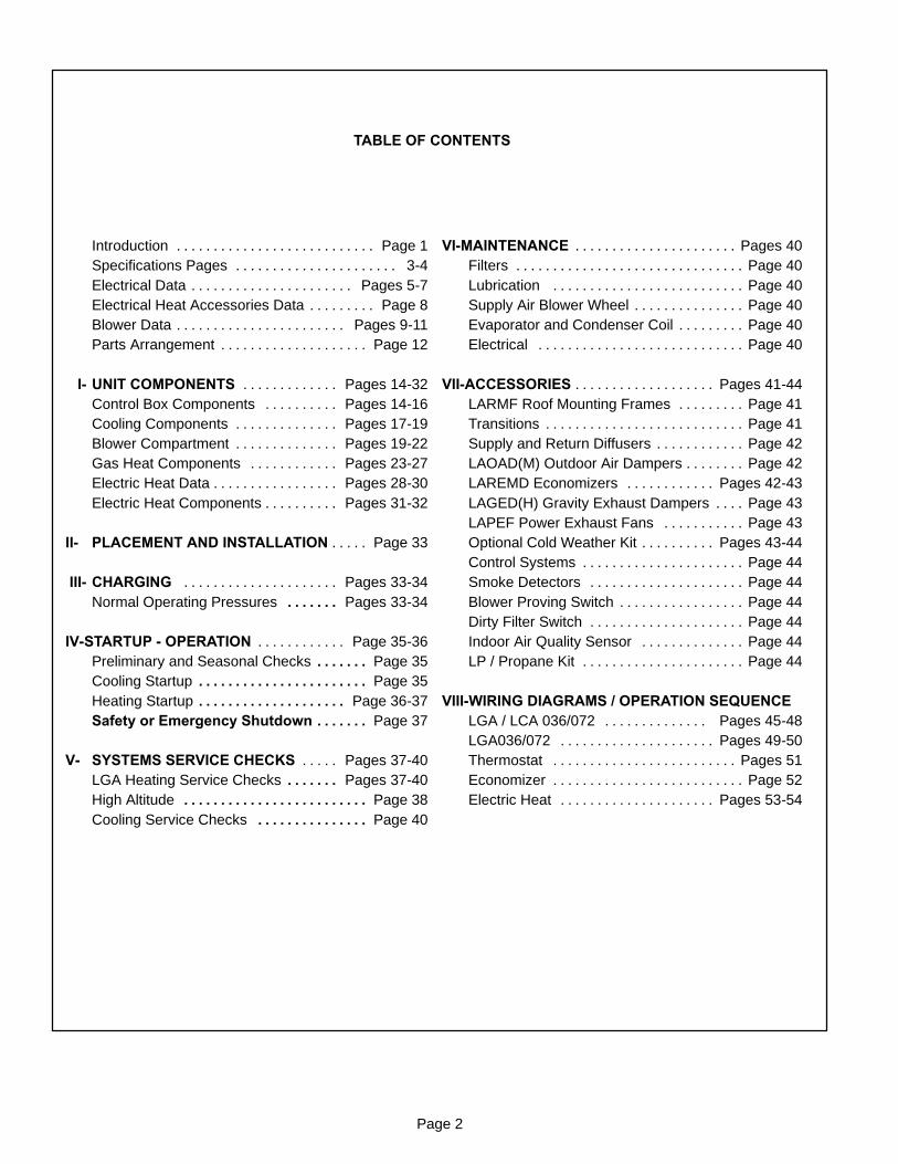
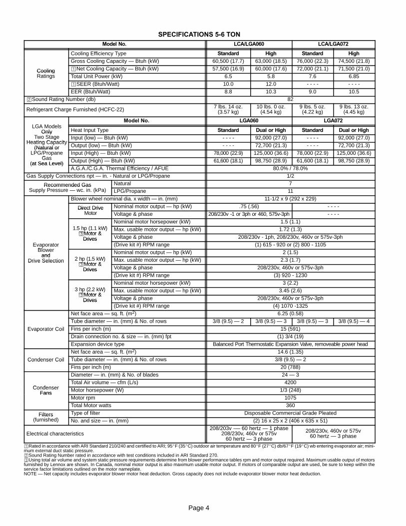
SPECIFICATIONS 5-6 TONModel No. LCA/LGA060 LCA/LGA072
Cooling Efficiency Type Standard High Standard HighGross Cooling Capacity — Btuh (kW) 60,500 (17.7) 63,000 (18.5) 76,000 (22.3) 74,500 (21.8)
Cooling ¡Net Cooling Capacity — Btuh (kW) 57,500 (16.9) 60,000 (17.6) 72,000 (21.1) 71,500 (21.0)CoolingRatings Total Unit Power (kW) 6.5 5.8 7.6 6.85Ratings
¡SEER (Btuh/Watt) 10.0 12.0 - - - - - - - -
EER (Btuh/Watt) 8.8 10.3 9.0 10.5©Sound Rating Number (db) 82
Refrigerant Charge Furnished (HCFC-22) 7 lbs. 14 oz.(3.57 kg)
10 lbs. 0 oz.(4.54 kg)
9 lbs. 5 oz.(4.22 kg)
9 lbs. 13 oz.(4.45 kg)
LGA ModelsModel No. LGA060 LGA072
LGA ModelsOnly
Two StageHeat Input Type Standard Dual or High Standard Dual or HighOnly
Two StageHeating Capacity
Input (low) — Btuh (kW) - - - - 92,000 (27.0) - - - - 92,000 (27.0)Two StageHeating Capacity
(Natural or Output (low) — Btuh (kW) - - - - 72,700 (21.3) - - - - 72,700 (21.3)(Natural orLPG/Propane
GasInput (High) — Btuh (kW) 78,000 (22.9) 125,000 (36.6) 78,000 (22.9) 125,000 (36.6)LPG/Propane
Gas(at Sea Level) Output (High) — Btuh (kW) 61,600 (18.1) 98,750 (28.9) 61,600 (18.1) 98,750 (28.9)(at Sea Level)
A.G.A./C.G.A. Thermal Efficiency / AFUE 80.0% / 78.0%Gas Supply Connections npt — in. - Natural or LPG/Propane 1/2
Recommended GasSupply Pressure — wc. in. (kPa)
Natural 7Recommended GasSupply Pressure — wc. in. (kPa) LPG/Propane 11
Blower wheel nominal dia. x width — in. (mm) 11-1/2 x 9 (292 x 229)
Direct DriveMotor
Nominal motor output — hp (kW) .75 (.56) - - - -Direct DriveMotor Voltage & phase 208/230v -1 or 3ph or 460, 575v-3ph - - - -
1.5 hp (1.1 kW)Nominal motor horsepower (kW) 1.5 (1.1)
1.5 hp (1.1 kW)¢Motor &
Max. usable motor output — hp (kW) 1.72 (1.3)¢Motor &
Drives Voltage & phase 208/230v - 1ph, 208/230v, 460v or 575v-3ph
EvaporatorBlower
Drives(Drive kit #) RPM range (1) 615 - 920 or (2) 800 - 1105Evaporator
Blowerand
2 hp (1.5 kW)Nominal motor output — hp (kW) 2 (1.5)
andDrive Selection 2 hp (1.5 kW)
¢Motor &Max. usable motor output — hp (kW) 2.3 (1.7)Drive Selection
¢Motor &Drives Voltage & phase 208/230v, 460v or 575v-3phDrives
(Drive kit #) RPM range (3) 920 - 1230
3 hp (2.2 kW)Nominal motor horsepower (kW) 3 (2.2)
3 hp (2.2 kW)¢Motor &
Max. usable motor output — hp (kW) 3.45 (2.6)¢Motor &
Drives Voltage & phase 208/230v, 460v or 575v-3phDrives(Drive kit #) RPM range (4) 1070 -1325
Net face area — sq. ft. (m2) 6.25 (0.58)
Tube diameter — in. (mm) & No. of rows 3/8 (9.5) — 2 3/8 (9.5) — 3 3/8 (9.5) — 3 3/8 (9.5) — 4
Evaporator Coil Fins per inch (m) 15 (591)Evaporator CoilDrain connection no. & size — in. (mm) fpt (1) 3/4 (19)
Expansion device type Balanced Port Thermostatic Expansion Valve, removeable power head
Net face area — sq. ft. (m2) 14.6 (1.35)
Condenser Coil Tube diameter — in. (mm) & No. of rows 3/8 (9.5) — 2Condenser CoilFins per inch (m) 20 (788)
Diameter — in. (mm) & No. of blades 24 — 3
CondenserTotal Air volume — cfm (L/s) 4200
CondenserFans Motor horsepower (W) 1/3 (248)Fans
Motor rpm 1075
Total Motor watts 360
Filters(furnished)
Type of filter Disposable Commercial Grade PleatedFilters(furnished) No. and size — in. (mm) (2) 16 x 25 x 2 (406 x 635 x 51)
Electrical characteristics208/203v -— 60 hertz — 1 phase
208/230v, 460v or 575v60 hertz — 3 phase
208/230v, 460v or 575v60 hertz — 3 phase
¡Rated in accordance with ARI Standard 210/240 and certified to ARI; 95_F (35_C) outdoor air temperature and 80_F (27_C) db/67_F (19_C) wb entering evaporator air; mini-mum external duct static pressure.©Sound Rating Number rated in accordance with test conditions included in ARI Standard 270.¢Using total air volume and system static pressure requirements determine from blower performance tables rpm and motor output required. Maximum usable output of motorsfurnished by Lennox are shown. In Canada, nominal motor output is also maximum usable motor output. If motors of comparable output are used, be sure to keep within theservice factor limitations outlined on the motor nameplate.NOTE — Net capacity includes evaporator blower motor heat deduction. Gross capacity does not include evaporator blower motor heat deduction.
Page 5
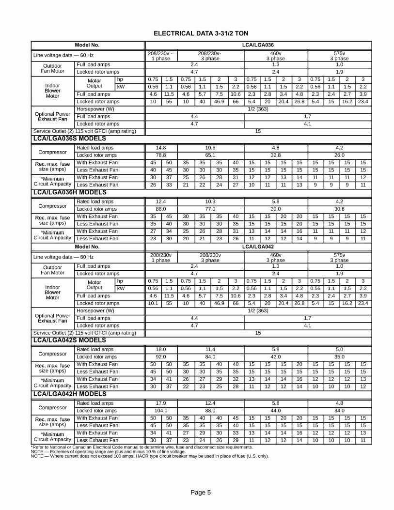
ELECTRICAL DATA 3-31/2 TON
Model No. LCA/LGA036
Line voltage data — 60 Hz 208/230v -1 phase
208/230v-3 phase
460v3 phase
575v3 phase
OutdoorFan Motor
Full load amps 2.4 1.3 1.0OutdoorFan Motor Locked rotor amps 4.7 2.4 1.9
IndoorMotorOutput
hp 0.75 1.5 0.75 1.5 2 3 0.75 1.5 2 3 0.75 1.5 2 3IndoorBlower
MotorOutput kW 0.56 1.1 0.56 1.1 1.5 2.2 0.56 1.1 1.5 2.2 0.56 1.1 1.5 2.2
BlowerMotor Full load amps 4.6 11.5 4.6 5.7 7.5 10.6 2.3 2.8 3.4 4.8 2.3 2.4 2.7 3.9Motor
Locked rotor amps 10 55 10 40 46.9 66 5.4 20 20.4 26.8 5.4 15 16.2 23.4
Optional PowerHorsepower (W) 1/2 (363)
Optional PowerExhaust Fan Full load amps 4.4 1.7Exhaust Fan
Locked rotor amps 4.7 4.1Service Outlet (2) 115 volt GFCI (amp rating) 15
LCA/LGA036S MODELS
CompressorRated load amps 14.8 10.6 4.8 4.2
Compressor Locked rotor amps 78.8 65.1 32.8 26.0
Rec. max. fusesize (amps)
With Exhaust Fan 45 50 35 35 35 40 15 15 15 15 15 15 15 15Rec. max. fusesize (amps) Less Exhaust Fan 40 45 30 30 30 35 15 15 15 15 15 15 15 15
*MinimumCircuit Ampacity
With Exhaust Fan 30 37 25 26 28 31 12 12 13 14 11 11 11 12*MinimumCircuit Ampacity Less Exhaust Fan 26 33 21 22 24 27 10 11 11 13 9 9 9 11
LCA/LGA036H MODELS
CompressorRated load amps 12.4 10.3 5.8 4.2
Compressor Locked rotor amps 88.0 77.0 39.0 30.6
Rec. max. fusesize (amps)
With Exhaust Fan 35 45 30 35 35 40 15 15 20 20 15 15 15 15Rec. max. fusesize (amps) Less Exhaust Fan 35 40 30 30 30 35 15 15 15 20 15 15 15 15
*MinimumCircuit Ampacity
With Exhaust Fan 27 34 25 26 28 31 13 14 14 16 11 11 11 12*MinimumCircuit Ampacity Less Exhaust Fan 23 30 20 21 23 26 11 12 12 14 9 9 9 11
Model No. LCA/LGA042
Line voltage data — 60 Hz 208/230v1 phase
208/230v3 phase
460v3 phase
575v3 phase
OutdoorFan Motor
Full load amps 2.4 1.3 1.0OutdoorFan Motor Locked rotor amps 4.7 2.4 1.9
IndoorMotorOutput
hp 0.75 1.5 0.75 1.5 2 3 0.75 1.5 2 3 0.75 1.5 2 3IndoorBlower
MotorOutput kW 0.56 1.1 0.56 1.1 1.5 2.2 0.56 1.1 1.5 2.2 0.56 1.1 1.5 2.2
BlowerMotor Full load amps 4.6 11.5 4.6 5.7 7.5 10.6 2.3 2.8 3.4 4.8 2.3 2.4 2.7 3.9Motor
Locked rotor amps 10.1 55 10 40 46.9 66 5.4 20 20.4 26.8 5.4 15 16.2 23.4
Optional PowerHorsepower (W) 1/2 (363)
Optional PowerExhaust Fan Full load amps 4.4 1.7Exhaust Fan
Locked rotor amps 4.7 4.1Service Outlet (2) 115 volt GFCI (amp rating) 15
LCA/LGA042S MODELS
CompressorRated load amps 18.0 11.4 5.8 5.0
Compressor Locked rotor amps 92.0 84.0 42.0 35.0
Rec. max. fusesize (amps)
With Exhaust Fan 50 50 35 35 40 40 15 15 15 20 15 15 15 15Rec. max. fusesize (amps) Less Exhaust Fan 45 50 30 30 35 35 15 15 15 15 15 15 15 15
*MinimumCircuit Ampacity
With Exhaust Fan 34 41 26 27 29 32 13 14 14 16 12 12 12 13*MinimumCircuit Ampacity Less Exhaust Fan 30 37 22 23 25 28 11 12 12 14 10 10 10 12
LCA/LGA042H MODELS
CompressorRated load amps 17.9 12.4 5.8 4.8
Compressor Locked rotor amps 104.0 88.0 44.0 34.0
Rec. max. fusesize (amps)
With Exhaust Fan 50 50 35 40 40 45 15 15 20 20 15 15 15 15Rec. max. fusesize (amps) Less Exhaust Fan 45 50 35 35 35 40 15 15 15 15 15 15 15 15
*MinimumCircuit Ampacity
With Exhaust Fan 34 41 27 29 30 33 13 14 14 16 12 12 12 13*MinimumCircuit Ampacity Less Exhaust Fan 30 37 23 24 26 29 11 12 12 14 10 10 10 11
*Refer to National or Canadian Electrical Code manual to determine wire, fuse and disconnect size requirements.NOTE — Extremes of operating range are plus and minus 10 % of line voltage.NOTE — Where current does not exceed 100 amps, HACR type circuit breaker may be used in place of fuse (U.S. only).

Page 6
ELECTRICAL DATA 4-5 TON
Model No. LCA/LGA048
Line voltage data — 60 Hz 208/230v1 phase
208/230v3 phase
460v3 phase
575v3 phase
OutdoorFan Motor
Full load amps 2.4 1.3 1.0OutdoorFan Motor Locked rotor amps 4.7 2.4 1.9
IndoorMotorOutput
hp 0.75 1.5 0.75 1.5 2 3 0.75 1.5 2 3 0.75 1.5 2 3IndoorBlower
MotorOutput kW 0.56 1.1 0.56 1.1 1.5 2.2 0.56 1.1 1.5 2.2 0.56 1.1 1.5 2.2
BlowerMotor Full load amps 4.6 11.5 4.6 5.7 7.5 10.6 2.3 2.8 3.4 4.8 2.3 2.4 2.7 3.9Motor
Locked rotor amps 10 55 10 40 46.9 66 5.4 20 20.4 26.8 5.4 15 16.2 23.4
Optional PowerHorsepower (W) 1/2 (363)
Optional PowerExhaust Fan Full load amps 4.4 1.7Exhaust Fan
Locked rotor amps 4.7 4.1Service Outlet (2) 115 volt GFCI (amp rating) 15
LCA/LGA048S MODELS
CompressorRated load amps each 23.4 12.2 7.1 5.8
Compressor Locked rotor amps each 110.0 90.0 46.0 37.0
Rec. max. fusesize (amps)
With Exhaust Fan 60 70 35 35 40 40 20 20 20 20 15 15 15 15Rec. max. fusesize (amps) Less Exhaust Fan 60 60 30 35 35 40 20 20 20 20 15 15 15 15
*MinimumCircuit Ampacity
With Exhaust Fan 41 48 27 28 30 33 15 15 16 17 13 13 13 14*MinimumCircuit Ampacity Less Exhaust Fan 37 44 23 24 26 29 13 13 14 15 11 11 11 13
LCA/LGA048H MODELS
CompressorRated load amps each 23.7 13.5 7.4 5.8
Compressor Locked rotor amps each 129.0 99.0 49.5 40.0
Rec. max. fusesize (amps)
With Exhaust Fan 60 70 40 40 40 45 20 20 20 20 15 15 15 15Rec. max. fusesize (amps) Less Exhaust Fan 60 60 35 35 40 40 20 20 20 20 15 15 15 15
*MinimumCircuit Ampacity
With Exhaust Fan 42 48 29 30 32 35 15 16 16 18 13 13 13 14*MinimumCircuit Ampacity Less Exhaust Fan 37 44 24 25 27 30 13 14 14 16 11 11 11 13
Model No. LCA/LGA060
Line voltage data — 60 Hz 208/230v -1 phase
208/230v3 phase
460v3 phase
575v3 phase
OutdoorFan Motor
Full load amps 2.4 1.3 1.0OutdoorFan Motor Locked rotor amps 4.7 2.4 1.9
IndoorMotorOutput
hp 0.75 1.5 0.75 1.5 2 3 0.75 1.5 2 3 0.75 1.5 2 3IndoorBlower
MotorOutput kW 0.56 1.1 0.56 1.1 1.5 2.2 0.56 1.1 1.5 2.2 0.56 1.1 1.5 2.2
BlowerMotor Full load amps 4.6 11.5 4.6 5.7 7.5 10.6 2.3 2.8 3.4 4.8 2.3 2.4 2.7 3.9Motor
Locked rotor amps 10 55 10 40 46.9 66 5.4 20 20.4 26.8 5.4 15 16.2 23.4
Optional PowerHorsepower (W) 1/2 (363)
Optional PowerExhaust Fan Full load amps 4.4 1.7Exhaust Fan
Locked rotor amps 4.7 4.1Service Outlet (2) 115 volt GFCI (amp rating) 15
LCA/LGA060S MODELS
CompressorRated load amps each 26.9 16.7 8.6 6.0
Compressor Locked rotor amps each 141.0 110.0 55.0 44.0
Rec. max. fusesize (amps)
With Exhaust Fan 70 70 45 50 50 50 20 25 25 25 15 15 15 20Rec. max. fusesize (amps) Less Exhaust Fan 60 70 40 45 45 50 20 20 20 25 15 15 15 15
*MinimumCircuit Ampacity
With Exhaust Fan 46 52 33 34 36 39 17 17 18 19 13 13 13 15*MinimumCircuit Ampacity Less Exhaust Fan 41 48 28 29 31 34 15 15 16 17 11 11 12 13
LCA/LGA060H MODELS
CompressorRated load amps each 28.8 17.3 9.0 7.1
Compressor Locked rotor amps each 169.0 123.0 62.0 50.0
Rec. max. fusesize (amps)
With Exhaust Fan 70 70 50 50 50 50 25 25 25 25 20 20 20 20Rec. max. fusesize (amps) Less Exhaust Fan 70 70 45 45 45 50 20 20 20 25 15 15 15 20
*MinimumCircuit Ampacity
With Exhaust Fan 48 55 34 35 36 40 17 18 18 20 14 14 15 16*MinimumCircuit Ampacity Less Exhaust Fan 44 50 29 30 32 35 15 16 16 18 13 13 13 14
*Refer to National or Canadian Electrical Code manual to determine wire, fuse and disconnect size requirements.NOTE — Extremes of operating range are plus and minus 10 % of line voltage.NOTE — Where current does not exceed 100 amps, HACR type circuit breaker may be used in place of fuse (U.S. only).
Page 7
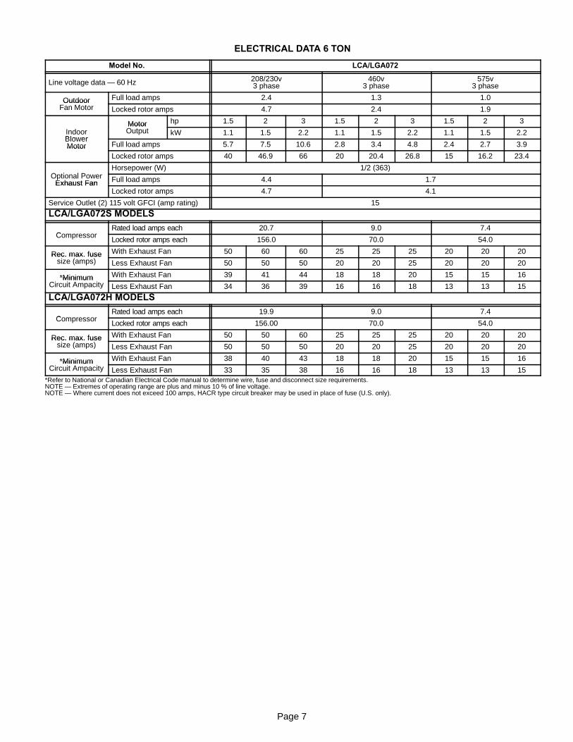
ELECTRICAL DATA 6 TON
Model No. LCA/LGA072
Line voltage data — 60 Hz 208/230v3 phase
460v3 phase
575v3 phase
OutdoorFan Motor
Full load amps 2.4 1.3 1.0OutdoorFan Motor Locked rotor amps 4.7 2.4 1.9
MotorOutput
hp 1.5 2 3 1.5 2 3 1.5 2 3
IndoorBlower
MotorOutput kW 1.1 1.5 2.2 1.1 1.5 2.2 1.1 1.5 2.2Indoor
BlowerMotor Full load amps 5.7 7.5 10.6 2.8 3.4 4.8 2.4 2.7 3.9Motor
Locked rotor amps 40 46.9 66 20 20.4 26.8 15 16.2 23.4
Optional PowerHorsepower (W) 1/2 (363)
Optional PowerExhaust Fan Full load amps 4.4 1.7Exhaust Fan
Locked rotor amps 4.7 4.1
Service Outlet (2) 115 volt GFCI (amp rating) 15
LCA/LGA072S MODELS
CompressorRated load amps each 20.7 9.0 7.4
CompressorLocked rotor amps each 156.0 70.0 54.0
Rec. max. fusesize (amps)
With Exhaust Fan 50 60 60 25 25 25 20 20 20Rec. max. fusesize (amps) Less Exhaust Fan 50 50 50 20 20 25 20 20 20
*MinimumCircuit Ampacity
With Exhaust Fan 39 41 44 18 18 20 15 15 16*MinimumCircuit Ampacity Less Exhaust Fan 34 36 39 16 16 18 13 13 15
LCA/LGA072H MODELS
CompressorRated load amps each 19.9 9.0 7.4
CompressorLocked rotor amps each 156.00 70.0 54.0
Rec. max. fusesize (amps)
With Exhaust Fan 50 50 60 25 25 25 20 20 20Rec. max. fusesize (amps) Less Exhaust Fan 50 50 50 20 20 25 20 20 20
*MinimumCircuit Ampacity
With Exhaust Fan 38 40 43 18 18 20 15 15 16*MinimumCircuit Ampacity Less Exhaust Fan 33 35 38 16 16 18 13 13 15
*Refer to National or Canadian Electrical Code manual to determine wire, fuse and disconnect size requirements.NOTE — Extremes of operating range are plus and minus 10 % of line voltage.NOTE — Where current does not exceed 100 amps, HACR type circuit breaker may be used in place of fuse (U.S. only).
Page 8
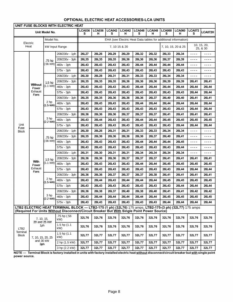
OPTIONAL ELECTRIC HEAT ACCESSORIES-LCA UNITS
UNIT FUSE BLOCKS WITH ELECTRIC HEAT
Unit Model No. LCA036S
LCA036H
LCA042S
LCA042H
LCA048S
LCA048H
LCA060S
LCA060H
LCA072S LCA072H
ElectricModel No. EHA (see Electric Heat Data tables for additional information)
ElectricHeat kW Input Range 7, 10 15 & 20 7, 10, 15, 20 & 25 10, 15, 20,
25, & 30
208/230v - 1ph 26L27 26L26 26L29 26L29 26L32 26L32 26L33 26L34 - - - - - - - -
.75 hp 208/230v - 3ph 26L35 26L35 26L35 26L36 26L36 26L36 26L37 26L39 - - - - - - - -.75 hp(.56 kW) 460v - 3ph 26L43 26L43 26L43 26L43 26L44 26L44 26L44 26L44 - - - - - - - -
575v - 3ph 26L43 26L43 26L43 26L43 26L43 26L43 26L43 26L43 - - - - - - - -
208/230v - 1ph 26L30 26L28 26L31 26L31 26L33 26L33 26L34 26L34 - - - - - - - -
Without1.5 hp 208/230v - 3ph 26L35 26L35 26L35 26L36 26L36 26L36 26L39 26L39 26L41 26L41
WithoutPower
1.5 hp(1.1 kW) 460v - 3ph 26L43 26L43 26L43 26L43 26L44 26L44 26L44 26L44 26L44 26L44Power
ExhaustFans
575v - 3ph 26L43 26L43 26L43 26L43 26L43 26L43 26L43 26L43 26L44 26L44Fans
2 hp208/230v - 3ph 26L35 26L35 26L36 26L36 26L36 26L37 26L40 26L40 26L41 26L41
2 hp(1.5 kW)
460v - 3ph 26L43 26L43 26L43 26L43 26L44 26L44 26L44 26L44 26L44 26L44(1.5 kW)
575v - 3ph 26L43 26L43 26L43 26L43 26L43 26L43 26L43 26L43 26L44 26L44
3 hp208/230v - 3ph 26L36 26L36 26L36 26L37 26L37 26L37 26L41 26L41 26L41 26L41
3 hp(2.2 kW)
460v - 3ph 26L43 26L44 26L43 26L43 26L44 26L44 26L45 26L45 26L45 26L45
UnitFuse
(2.2 kW)575v - 3ph 26L43 26L43 26L43 26L43 26L43 26L43 26L43 26L44 26L44 26L44
FuseBlock 208/230v - 1ph 26L30 26L26 26L31 26L31 26L33 26L33 26L34 26L34 - - - - - - - -Block
.75 hp 208/230v - 3ph 26L35 26L36 26L36 26L36 26L36 26L37 26L40 26L41 - - - - - - - -.75 hp(.56 kW) 460v - 3ph 26L43 26L43 26L43 26L43 26L44 26L44 26L44 26L45 - - - - - - - -
575v - 3ph 26L43 26L43 26L43 26L43 26L43 26L43 26L43 26L44 - - - - - - - -
208/230v - 1ph 26L31 26L30 26L31 26L31 26L34 26L34 26L34 26L34 - - - - - - - -
With1.5 hp 208/230v - 3ph 26L36 26L36 26L36 26L37 26L37 26L37 26L41 26L41 26L41 26L41
WithPower
1.5 hp(1.1 kW) 460v - 3ph 26L43 26L43 26L43 26L43 26L44 26L44 26L45 26L45 26L45 26L45Power
ExhaustFans
575v - 3ph 26L43 26L43 26L43 26L43 26L43 26L43 26L43 26L44 26L44 26L44Fans
2 hp208/230v - 3ph 26L36 26L36 26L37 26L37 26L37 26L38 26L41 26L41 26L41 26L41
2 hp(1.5 kW)
460v - 3ph 26L43 26L44 26L43 26L44 26L44 26L44 26L45 26L45 26L45 26L45(1.5 kW)
575v - 3ph 26L43 26L43 26L43 26L43 26L43 26L43 26L43 26L44 26L44 26L44
3 hp208/230v - 3ph 26L36 26L38 26L37 26L40 26L38 26L40 26L41 26L41 26L42 26L42
3 hp(2.2 kW)
460v - 3ph 26L43 26L44 26L44 26L44 26L44 26L44 26L45 26L45 26L45 26L45(2.2 kW)
575v - 3ph 26L43 26L43 26L43 26L43 26L43 26L43 26L44 26L44 26L44 26L44
LTB2 ELECTRIC HEAT TERMINAL BLOCK — LTB2-175 (1 ph) (32L76) 175 amps, LTB2-175-(3 ph) (32L77) 175 amps(Required For Units Without Disconnect/Circuit Breaker But With Single Point Power Source)
7, 10, 15,20 and 25 kW
.75 hp (.56kW) 32L76 32L76 32L76 32L76 32L76 32L76 32L76 32L76 32L76 32L76
LTB2Terminal
20 and 25 kW1ph 1.5 hp (1.1
kW) 32L76 32L76 32L76 32L76 32L76 32L76 32L76 32L76 32L76 32L76LTB2
TerminalBlock
7, 10, 15, 20, 25and 30 kW
1.5 hp (1.1kW) 32L77 32L77 32L77 32L77 32L77 32L77 32L77 32L77 32L77 32L77
7, 10, 15, 20, 25and 30 kW
3ph 2 hp (1.5 kW) 32L77 32L77 32L77 32L77 32L77 32L77 32L77 32L77 32L77 32L773ph3 hp (2.2 kW) 32L77 32L77 32L77 32L77 32L77 32L77 32L77 32L77 32L77 32L77
NOTE — Terminal Block is factory installed in units with factory installed electric heat without disconnect/circuit breaker but with single pointpower source.
Page 9
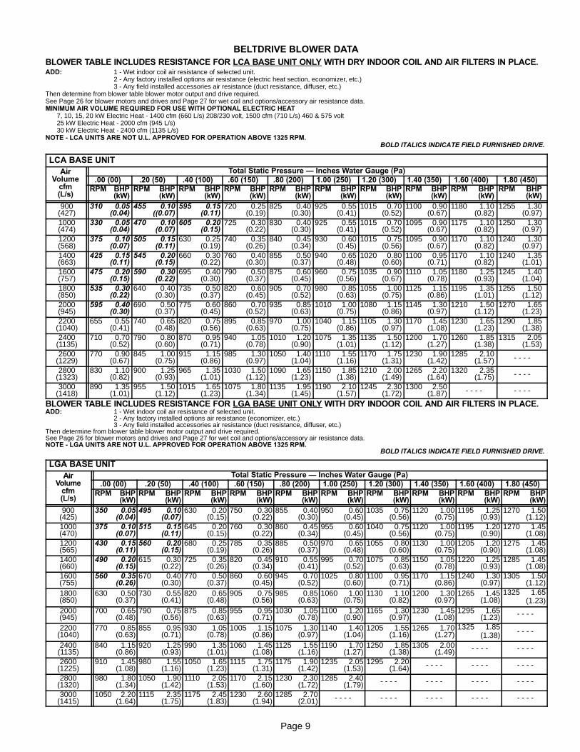
BELTDRIVE BLOWER DATABLOWER TABLE INCLUDES RESISTANCE FOR LCA BASE UNIT ONLY WITH DRY INDOOR COIL AND AIR FILTERS IN PLACE.ADD: 1 - Wet indoor coil air resistance of selected unit.
2 - Any factory installed options air resistance (electric heat section, economizer, etc.)3 - Any field installed accessories air resistance (duct resistance, diffuser, etc.)
Then determine from blower table blower motor output and drive required.See Page 26 for blower motors and drives and Page 27 for wet coil and options/accessory air resistance data.MINIMUM AIR VOLUME REQUIRED FOR USE WITH OPTIONAL ELECTRIC HEAT
7, 10, 15, 20 kW Electric Heat - 1400 cfm (660 L/s) 208/230 volt, 1500 cfm (710 L/s) 460 & 575 volt25 kW Electric Heat - 2000 cfm (945 L/s)30 kW Electric Heat - 2400 cfm (1135 L/s)
NOTE - LCA UNITS ARE NOT U.L. APPROVED FOR OPERATION ABOVE 1325 RPM.BOLD ITALICS INDICATE FIELD FURNISHED DRIVE.
LCA BASE UNITAir
VolumeTotal Static Pressure — Inches Water Gauge (Pa)Air
Volumecfm
.00 (00) .20 (50) .40 (100) .60 (150) .80 (200) 1.00 (250) 1.20 (300) 1.40 (350) 1.60 (400) 1.80 (450)Volumecfm(L/s)
RPM BHP(kW)
RPM BHP(kW)
RPM BHP(kW)
RPM BHP(kW)
RPM BHP(kW)
RPM BHP(kW)
RPM BHP(kW)
RPM BHP(kW)
RPM BHP(kW)
RPM BHP(kW)
900(427)
310 0.05(0.04)
455 0.10((0.07)
595 0.15(0.11)
720 0.25(0.19)
825 0.40(0.30)
925 0.55(0.41)
1015 0.70(0.52)
1100 0.90(0.67)
1180 1.10(0.82)
1255 1.30(0.97)
1000(474)
330 0.05(0.04)
470 0.10(0.07)
605 0.20(0.15)
725 0.30(0.22)
830 0.40(0.30)
925 0.55(0.41)
1015 0.70(0.52)
1095 0.90(0.67)
1175 1.10(0.82)
1250 1.30(0.97)
1200(568)
375 0.10(0.07)
505 0.15(0.11)
630 0.25(0.19)
740 0.35(0.26)
840 0.45(0.34)
930 0.60(0.45)
1015 0.75(0.56)
1095 0.90(0.67)
1170 1.10(0.82)
1240 1.30(0.97)
1400(663)
425 0.15(0.11)
545 0.20(0.15)
660 0.30(0.22)
760 0.40(0.30)
855 0.50(0.37)
940 0.65(0.48)
1020 0.80(0.60)
1100 0.95(0.71)
1170 1.10(0.82)
1240 1.35(1.01)
1600(757)
475 0.20(0.15)
590 0.30(0.22)
695 0.40(0.30)
790 0.50(0.37)
875 0.60(0.45)
960 0.75(0.56)
1035 0.90(0.67)
1110 1.05(0.78)
1180 1.25(0.93)
1245 1.40(1.04)
1800(850)
535 0.30(0.22)
640 0.40(0.30)
735 0.50(0.37)
820 0.60(0.45)
905 0.70(0.52)
980 0.85(0.63)
1055 1.00(0.75)
1125 1.15(0.86)
1195 1.35(1.01)
1255 1.50(1.12)
2000(945)
595 0.40(0.30)
690 0.50(0.37)
775 0.60(0.45)
860 0.70(0.52)
935 0.85(0.63)
1010 1.00(0.75)
1080 1.15(0.86)
1145 1.30(0.97)
1210 1.50(1.12)
1270 1.65(1.23)
2200(1040)
655 0.55(0.41)
740 0.65(0.48)
820 0.75(0.56)
895 0.85(0.63)
970 1.00(0.75)
1040 1.15(0.86)
1105 1.30(0.97)
1170 1.45(1.08)
1230 1.65(1.23)
1290 1.85(1.38)
2400(1135)
710 0.70(0.52)
790 0.80(0.60)
870 0.95(0.71)
940 1.05(0.78)
1010 1.20(0.90)
1075 1.35(1.01)
1135 1.50(1.12)
1200 1.70(1.27)
1260 1.85(1.38)
1315 2.05(1.53)
2600(1229)
770 0.90(0.67)
845 1.00(0.75)
915 1.15(0.86)
985 1.30(0.97)
1050 1.40(1.04)
1110 1.55(1.16)
1170 1.75(1.31)
1230 1.90(1.42)
1285 2.10(1.57) - - - -
2800(1323)
830 1.10(0.82)
900 1.25(0.93)
965 1.35(1.01)
1030 1.50(1.12)
1090 1.65(1.23)
1150 1.85(1.38)
1210 2.00(1.49)
1265 2.20(1.64)
1320 2.35(1.75) - - - -
3000(1418)
890 1.35(1.01)
955 1.50(1.12)
1015 1.65(1.23)
1075 1.80(1.34)
1135 1.95(1.45)
1190 2.10(1.57)
1245 2.30(1.72)
1300 2.50(1.87) - - - - - - - -
BLOWER TABLE INCLUDES RESISTANCE FOR LGA BASE UNIT ONLY WITH DRY INDOOR COIL AND AIR FILTERS IN PLACE.ADD: 1 - Wet indoor coil air resistance of selected unit.
2 - Any factory installed options air resistance (economizer, etc.)3 - Any field installed accessories air resistance (duct resistance, diffuser, etc.)
Then determine from blower table blower motor output and drive required.See Page 26 for blower motors and drives and Page 27 for wet coil and options/accessory air resistance data.NOTE - LGA UNITS ARE NOT U.L. APPROVED FOR OPERATION ABOVE 1325 RPM.
BOLD ITALICS INDICATE FIELD FURNISHED DRIVE.
LGA BASE UNITAir
VolumeTotal Static Pressure — Inches Water Gauge (Pa)Air
Volumecfm
.00 (00) .20 (50) .40 (100) .60 (150) .80 (200) 1.00 (250) 1.20 (300) 1.40 (350) 1.60 (400) 1.80 (450)Volumecfm(L/s)
RPM BHP(kW)
RPM BHP(kW)
RPM BHP(kW)
RPM BHP(kW)
RPM BHP(kW)
RPM BHP(kW)
RPM BHP(kW)
RPM BHP(kW)
RPM BHP(kW)
RPM BHP(kW)
900(425)
350 0.05(0.04)
495 0.10(0.07)
630 0.20(0.15)
750 0.30(0.22)
855 0.40(0.30)
950 0.60(0.45)
1035 0.75(0.56)
1120 1.00(0.75)
1195 1.25(0.93)
1270 1.50(1.12)
1000(470)
375 0.10(0.07)
515 0.15(0.11)
645 0.20(0.15)
760 0.30(0.22)
860 0.45(0.34)
955 0.60(0.45)
1040 0.75(0.56)
1120 1.00(0.75)
1195 1.20(0.90)
1270 1.45(1.08)
1200(565)
430 0.15(0.11)
560 0.20(0.15)
680 0.25(0.19)
785 0.35(0.26)
885 0.50(0.37)
970 0.65(0.48)
1055 0.80(0.60)
1130 1.00(0.75)
1205 1.20(0.90)
1275 1.45(1.08)
1400(660)
490 0.20(0.15)
615 0.30(0.22)
725 0.35(0.26)
820 0.45(0.34)
910 0.55(0.41)
995 0.70(0.52)
1075 0.85(0.63)
1150 1.05(0.78)
1220 1.25(0.93)
1285 1.45(1.08)
1600(755)
560 0.35(0.26)
670 0.40(0.30)
770 0.50(0.37)
860 0.60(0.45)
945 0.70(0.52)
1025 0.80(0.60)
1100 0.95(0.71)
1170 1.15(0.86)
1240 1.30(0.97)
1305 1.50(1.12)
1800(850)
630 0.50(0.37)
730 0.55(0.41)
820 0.65(0.48)
905 0.75(0.56)
985 0.85(0.63)
1060 1.00(0.75)
1130 1.10(0.82)
1200 1.30(0.97)
1265 1.45(1.08)
1325 1.65(1.23)
2000(945)
700 0.65(0.48)
790 0.75(0.56)
875 0.85(0.63)
955 0.95(0.71)
1030 1.05(0.78)
1100 1.20(0.90)
1165 1.30(0.97)
1230 1.45(1.08)
1295 1.65(1.23) - - - -
2200(1040)
770 0.85(0.63)
855 0.95(0.71)
930 1.05(0.78)
1005 1.15(0.86)
1075 1.30(0.97)
1140 1.40(1.04)
1205 1.55(1.16)
1265 1.70(1.27)
1325 1.85(1.38) - - - -
2400(1135)
840 1.15(0.86)
920 1.25(0.93)
990 1.35(1.01)
1060 1.45(1.08)
1125 1.55(1.16)
1190 1.70(1.27)
1250 1.85(1.38)
1305 2.00(1.49) - - - - - - - -
2600(1225)
910 1.45(1.08)
980 1.55(1.16)
1050 1.65(1.23)
1115 1.75(1.31)
1175 1.90(1.42)
1235 2.05(1.53)
1295 2.20(1.64) - - - - - - - - - - - -
2800(1320)
980 1.80(1.34)
1050 1.90(1.42)
1110 2.05(1.53)
1170 2.15(1.60)
1230 2.30(1.72)
1285 2.40(1.79) - - - - - - - - - - - - - - - -
3000(1415)
1050 2.20(1.64)
1115 2.35(1.75)
1175 2.45(1.83)
1230 2.60(1.94)
1285 2.70(2.01) - - - - - - - - - - - - - - - - - - - -
Page 10
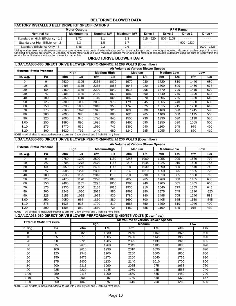
BELTDRIVE BLOWER DATAFACTORY INSTALLED BELT DRIVE KIT SPECIFICATIONS
Motor Outputs RPM RangeNominal hp Maximum hp Nominal kW Maximum kW Drive 1 Drive 2 Drive 3 Drive 4
Standard or High Efficiency - 1.5 1.72 1.1 1.3 615 - 920 800 - 1105 - - - - - - - -Standard or High Efficiency - 2 2.3 1.5 1.7 - - - - - - - - 920 - 1230 - - - -
Standard Efficiency Only - 3 3.45 2.2 2.6 - - - - - - - - - - - - 1070 - 1325*Using total air volume and system static pressure requirements determine from blower performance tables rpm and motor output required. Maximum usable output of motorsfurnished by Lennox are shown. In Canada, nominal motor output is also maximum usable motor output. If motors of comparable output are used, be sure to keep within theservice factor limitations outlined on the motor nameplate.
DIRECTDRIVE BLOWER DATA
LGA/LCA036-060 DIRECT DRIVE BLOWER PERFORMANCE @ 208 VOLTS (Downflow)
External Static PressureAir Volume at Various Blower Speeds
External Static PressureHigh Medium-High Medium Medium-Low Low
in. w.g. Pa cfm L/s cfm L/s cfm L/s cfm L/s cfm L/s
0 0 2530 1195 2265 1070 1970 930 1720 810 1440 680.10 25 2495 1175 2235 1055 1945 920 1700 800 1430 675.20 50 2450 1155 2200 1040 1915 905 1670 790 1415 670.30 75 2405 1135 2160 1020 1880 890 1640 775 1390 655.40 100 2355 1110 2115 1000 1840 870 1605 755 1360 640.50 125 2300 1085 2065 975 1795 845 1565 740 1330 630.60 150 2235 1055 2010 950 1745 825 1515 715 1290 610.70 175 2165 1020 1945 920 1690 800 1460 690 1245 590.80 200 2090 985 1875 885 1620 765 1400 660 1195 565.90 225 2000 945 1790 845 1550 730 1330 630 1130 535
1.00 250 1895 895 1695 800 1460 690 1250 590 1055 5001.10 275 1770 835 1580 745 1360 640 1160 545 975 4601.20 300 1620 765 1440 680 1240 585 1055 500 870 410
NOTE — All air data is measured external to unit with 2 row dry coil and 2 inch (51 mm) filters.
LGA/LCA036-060 DIRECT DRIVE BLOWER PERFORMANCE @ 230 VOLTS (Downflow)
External Static PressureAir Volume at Various Blower Speeds
External Static PressureHigh Medium-High Medium Medium-Low Low
in. w.g. Pa cfm L/s cfm L/s cfm L/s cfm L/s cfm L/s
0 0 2750 1300 2500 1180 2245 1060 1955 925 1630 770.10 25 2705 1275 2470 1165 2215 1045 1925 910 1600 755.20 50 2650 1250 2430 1145 2180 1030 1890 890 1570 740.30 75 2585 1220 2390 1130 2140 1010 1850 875 1535 725.40 100 2535 1195 2340 1105 2100 990 1810 855 1500 710.50 125 2475 1170 2290 1080 2050 965 1760 830 1455 685.60 150 2405 1135 2225 1050 1995 940 1705 805 1405 665.70 175 2330 1100 2155 1015 1930 910 1640 775 1365 645.80 200 2245 1060 2075 980 1865 880 1575 745 1310 620.90 225 2155 1015 1975 930 1780 840 1495 705 1240 585
1.00 250 2050 965 1860 880 1690 800 1405 665 1150 5451.10 275 1935 915 1720 810 1585 750 1290 610 1040 4901.20 300 1805 850 1560 735 1450 685 1160 545 915 430
NOTE — All air data is measured external to unit with 2 row dry coil and 2 inch (51 mm) filters.
LGA/LCA036-060 DIRECT DRIVE BLOWER PERFORMANCE @ 460/575 VOLTS (Downflow)
External Static PressureAir Volume at Various Blower Speeds
External Static PressureHigh Medium Low
in. w.g. Pa cfm L/s cfm L/s cfm L/s
0 0 2820 1330 2460 1160 1975 930.10 25 2770 1305 2430 1145 1950 920.20 50 2720 1285 2395 1130 1920 905.30 75 2670 1260 2345 1105 1885 890.40 100 2610 1230 2310 1090 1845 870.50 125 2545 1200 2260 1065 1800 850.60 150 2475 1170 2200 1040 1755 830.70 175 2400 1130 2140 1010 1700 800.80 200 2315 1090 2065 975 1635 770.90 225 2220 1045 1980 935 1565 740
1.00 250 2115 1000 1880 885 1480 7001.10 275 2000 945 1760 830 1370 6471.20 300 1860 875 1615 760 1260 595
NOTE — All air data is measured external to unit with 2 row dry coil and 2 inch (51 mm) filters.
Page 11
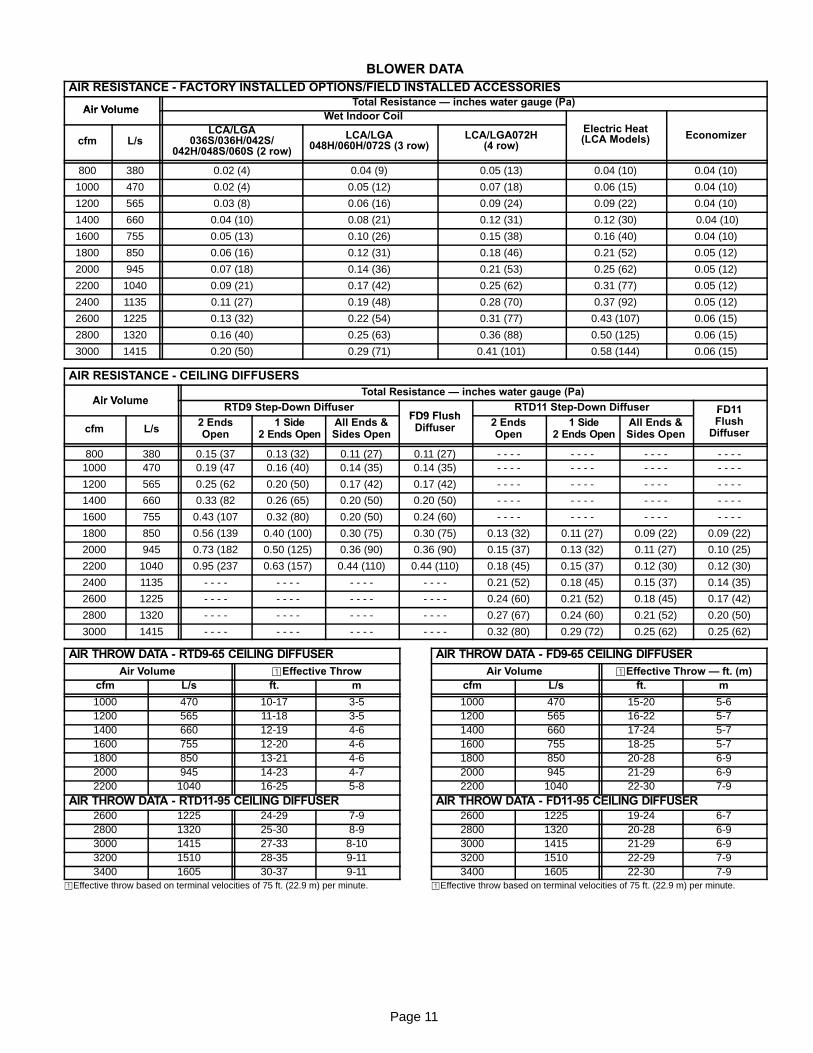
BLOWER DATAAIR RESISTANCE - FACTORY INSTALLED OPTIONS/FIELD INSTALLED ACCESSORIES
Air VolumeTotal Resistance — inches water gauge (Pa)
Air VolumeWet Indoor Coil
Electric Heatcfm L/s
LCA/LGA036S/036H/042S/
042H/048S/060S (2 row)
LCA/LGA048H/060H/072S (3 row)
LCA/LGA072H(4 row)
Electric Heat(LCA Models) Economizer
800 380 0.02 (4) 0.04 (9) 0.05 (13) 0.04 (10) 0.04 (10)
1000 470 0.02 (4) 0.05 (12) 0.07 (18) 0.06 (15) 0.04 (10)
1200 565 0.03 (8) 0.06 (16) 0.09 (24) 0.09 (22) 0.04 (10)
1400 660 0.04 (10) 0.08 (21) 0.12 (31) 0.12 (30) 0.04 (10)
1600 755 0.05 (13) 0.10 (26) 0.15 (38) 0.16 (40) 0.04 (10)
1800 850 0.06 (16) 0.12 (31) 0.18 (46) 0.21 (52) 0.05 (12)
2000 945 0.07 (18) 0.14 (36) 0.21 (53) 0.25 (62) 0.05 (12)
2200 1040 0.09 (21) 0.17 (42) 0.25 (62) 0.31 (77) 0.05 (12)
2400 1135 0.11 (27) 0.19 (48) 0.28 (70) 0.37 (92) 0.05 (12)
2600 1225 0.13 (32) 0.22 (54) 0.31 (77) 0.43 (107) 0.06 (15)
2800 1320 0.16 (40) 0.25 (63) 0.36 (88) 0.50 (125) 0.06 (15)
3000 1415 0.20 (50) 0.29 (71) 0.41 (101) 0.58 (144) 0.06 (15)
AIR RESISTANCE - CEILING DIFFUSERS
Air VolumeTotal Resistance — inches water gauge (Pa)
Air VolumeRTD9 Step-Down Diffuser
FD9 FlushRTD11 Step-Down Diffuser FD11
cfm L/s2 EndsOpen
1 Side2 Ends Open
All Ends &Sides Open
FD9 FlushDiffuser 2 Ends
Open1 Side
2 Ends OpenAll Ends &Sides Open
FD11Flush
Diffuser
800 380 0.15 (37 0.13 (32) 0.11 (27) 0.11 (27) - - - - - - - - - - - - - - - -1000 470 0.19 (47 0.16 (40) 0.14 (35) 0.14 (35) - - - - - - - - - - - - - - - -
1200 565 0.25 (62 0.20 (50) 0.17 (42) 0.17 (42) - - - - - - - - - - - - - - - -
1400 660 0.33 (82 0.26 (65) 0.20 (50) 0.20 (50) - - - - - - - - - - - - - - - -
1600 755 0.43 (107 0.32 (80) 0.20 (50) 0.24 (60) - - - - - - - - - - - - - - - -
1800 850 0.56 (139 0.40 (100) 0.30 (75) 0.30 (75) 0.13 (32) 0.11 (27) 0.09 (22) 0.09 (22)
2000 945 0.73 (182 0.50 (125) 0.36 (90) 0.36 (90) 0.15 (37) 0.13 (32) 0.11 (27) 0.10 (25)
2200 1040 0.95 (237 0.63 (157) 0.44 (110) 0.44 (110) 0.18 (45) 0.15 (37) 0.12 (30) 0.12 (30)
2400 1135 - - - - - - - - - - - - - - - - 0.21 (52) 0.18 (45) 0.15 (37) 0.14 (35)
2600 1225 - - - - - - - - - - - - - - - - 0.24 (60) 0.21 (52) 0.18 (45) 0.17 (42)
2800 1320 - - - - - - - - - - - - - - - - 0.27 (67) 0.24 (60) 0.21 (52) 0.20 (50)
3000 1415 - - - - - - - - - - - - - - - - 0.32 (80) 0.29 (72) 0.25 (62) 0.25 (62)
AIR THROW DATA - RTD9-65 CEILING DIFFUSERAir Volume ¡Effective Throw
cfm L/s ft. m
1000 470 10-17 3-51200 565 11-18 3-51400 660 12-19 4-61600 755 12-20 4-61800 850 13-21 4-62000 945 14-23 4-72200 1040 16-25 5-8
AIR THROW DATA - RTD11-95 CEILING DIFFUSER2600 1225 24-29 7-92800 1320 25-30 8-93000 1415 27-33 8-103200 1510 28-35 9-113400 1605 30-37 9-11
¡Effective throw based on terminal velocities of 75 ft. (22.9 m) per minute.
AIR THROW DATA - FD9-65 CEILING DIFFUSERAir Volume ¡Effective Throw — ft. (m)
cfm L/s ft. m
1000 470 15-20 5-61200 565 16-22 5-71400 660 17-24 5-71600 755 18-25 5-71800 850 20-28 6-92000 945 21-29 6-92200 1040 22-30 7-9
AIR THROW DATA - FD11-95 CEILING DIFFUSER2600 1225 19-24 6-72800 1320 20-28 6-93000 1415 21-29 6-93200 1510 22-29 7-93400 1605 22-30 7-9
¡Effective throw based on terminal velocities of 75 ft. (22.9 m) per minute.
Page 12
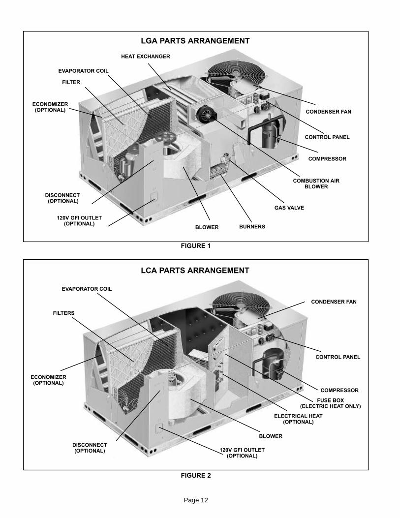
LGA PARTS ARRANGEMENT
FIGURE 1
HEAT EXCHANGER
EVAPORATOR COIL
FILTER
ECONOMIZER(OPTIONAL)
DISCONNECT(OPTIONAL)
120V GFI OUTLET(OPTIONAL)
BLOWER BURNERS
GAS VALVE
COMBUSTION AIRBLOWER
COMPRESSOR
CONDENSER FAN
CONTROL PANEL
LCA PARTS ARRANGEMENT
FIGURE 2
EVAPORATOR COIL
FILTERS
ECONOMIZER(OPTIONAL)
DISCONNECT(OPTIONAL) 120V GFI OUTLET
(OPTIONAL)
BLOWER
ELECTRICAL HEAT(OPTIONAL)
COMPRESSOR
CONTROL PANEL
CONDENSER FAN
FUSE BOX(ELECTRIC HEAT ONLY)
Page 13
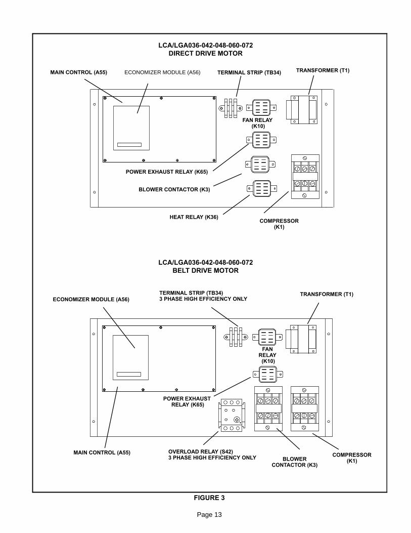
FIGURE 3
LCA/LGA036-042-048-060-072DIRECT DRIVE MOTOR
LCA/LGA036-042-048-060-072BELT DRIVE MOTOR
MAIN CONTROL (A55) ECONOMIZER MODULE (A56)
FAN RELAY(K10)
BLOWER CONTACTOR (K3)
HEAT RELAY (K36)COMPRESSOR
(K1)
TRANSFORMER (T1)
MAIN CONTROL (A55)
ECONOMIZER MODULE (A56)TERMINAL STRIP (TB34)3 PHASE HIGH EFFICIENCY ONLY
TERMINAL STRIP (TB34)
TRANSFORMER (T1)
FANRELAY(K10)
BLOWERCONTACTOR (K3)
COMPRESSOR(K1)
OVERLOAD RELAY (S42)3 PHASE HIGH EFFICIENCY ONLY
POWER EXHAUST RELAY (K65)
POWER EXHAUSTRELAY (K65)
Page 14
I-UNIT COMPONENTSLGA / LCA units are configure to order units (CTO). TheLGA and LCA unit components are shown in figures 1 and 2.L1, L2, and L3 wiring is color coded; L1 is red, L2 is yellow,and L3 is blue.
A-Control Box ComponentsLGA/LCA control box components are shown in figure 3.The control box is located in the upper portion of the com-pressor compartment.
1-Disconnect Switch S48 (Optional all units)LGA/LCA units may be equipped with an optional disconnectswitch S48. Other factory or field installed optional circuitbreakers may be used, such as CB10. S48 and CB10 aretoggle switches, which can be used by the service techni-cian to disconnect power to the unit.
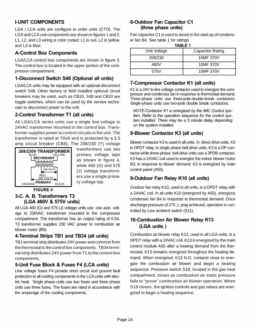
2-Control Transformer T1 (all units)All LGA/LCA series units use a single line voltage to24VAC transformer mounted in the control box. Trans-former supplies power to control circuits in the unit. Thetransformer is rated at 70VA and is protected by a 3.5amp circuit breaker (CB8). The 208/230 (Y) voltage
transformers use twoprimary voltage tapsas shown in figure 4,while 460 (G) and 575(J) voltage transform-ers use a single prima-ry voltage tap.
3-C. A. B. Transformers T3(LGA 460V & 575V units)
All LGA 460 (G) and 575 (J) voltage units use one auto volt-age to 230VAC transformer mounted in the compressorcompartment. The transformer has an output rating of 0.5A.T3 transformer supplies 230 VAC power to combustion airblower motor (B6).
4-Terminal Strips TB1 and TB34 (all units)TB1 terminal strip distributes 24V power and common fromthe thermostat to the control box components. TB34 termi-nal strip distributes 24V power from T1 to the control boxcomponents.
5-Unit Fuse Block & Fuses F4 (LCA units)Line voltage fuses F4 provide short circuit and ground faultprotection to all cooling components in the LCA units with elec-tric heat. Single phase units use two fuses and three phaseunits use three fuses. The fuses are rated in accordance withthe amperage of the cooling components.
6-Outdoor Fan Capacitor C1(three phase units)
Fan capacitor C1 is used to assist in the start up of condens-er fan B4. See table 1 for ratings
TABLE 1Unit Voltage Capacitor Rating
208/230 10MF 370V
460V 10MF 370V
575V 10MF 370V
7-Compressor Contactor K1 (all units)K1 is a 24V to line voltage contactor used to energize the com-pressor and condenser fan in response to thermostat demand.Three-phase units use three-pole-double-break contactors.Single-phase units use two-pole double break contactors.
NOTE-Contactor K1 is energized by the IMC Control sys-tem. Refer to the operation sequence for the control sys-tem installed. There may be a 5 minute delay dependingon the system installed.
8-Blower Contactor K3 (all units)
Blower contactor K3 is used in all units. In direct drive units, K3is DPDT relay. In single phase belt drive units, K3 is a DP con-tactor while three-phase belt drive units use a 3PDB contactor.K3 has a 24VAC coil used to energize the indoor blower motorB3, in response to blower demand. K3 is energized by maincontrol panel (A55).
9-Outdoor Fan Relay K10 (all units)
Outdoor fan relay K10, used in all units, is a DPDT relay witha 24VAC coil. In all units K10 (energized by A55), energizescondenser fan B4 in response to thermostat demand. Oncedischarge pressure of 275 ¦ psig achieved, operation is con-trolled by Low ambient switch (S11).
10-Combustion Air Blower Relay K13(LGA units )
Combustion air blower relay K13, used in all LGA units, is aDPDT relay with a 24VAC coil. K13 is energized by the maincontrol module A55 after a heating demand from the ther-mostat. K13 remains energized throughout the heating de-mand. When energized, K13 N.O. contacts close to ener-gize the combustion air blower and begin a heatingsequence. Pressure switch S18, located in the gas heatcompartment, closes as combustion air static pressurefalls to “prove” combustion air blower operation. WhenS18 closes, the ignition controls and gas valves are ener-gized to begin a heating sequence.
FIGURE 4
BLUE YELLOW
ORANGE
RED
BLACK
230 VOLTS
208 VOLTS
PRIMARY
SECONDARY
208/230V TRANSFORMER
Page 15
11-Power Exhaust Relay K65 (PEF units)Power exhaust relay K65 is a DPDT relay with a 24VACcoil. K65 is used in all LGA/LCA units equipped with theoptional power exhaust fans. K65 is energized by theeconomizer control panel (A56), after the economizerdampers reach 50% open (adjustable in ECTO). WhenK65 closes, the exhaust fan B10 is energized.
12-Blower Motor Overload Relay S42 (unitswith high efficiency motors)
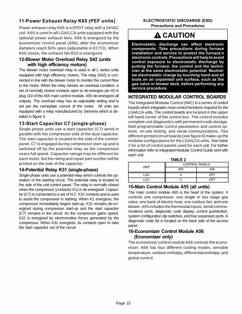
The blower motor overload relay is used in all L series unitsequipped with high efficiency motors. The relay (S42) is con-nected in line with the blower motor to monitor the current flowto the motor. When the relay senses an overload condition, aset of normally closed contacts open to de-energize pin #9 inplug 110 of the A55 main control module. A55 de-energizes alloutputs. The overload relay has an adjustable setting and isset per the nameplate current of the motor. All units areequipped with a relay manufactured by Siemens which is de-tailed in figure 5.
13-Start Capacitor C7 (single-phase)Single-phase units use a start capacitor (C7) wired inparallel with the compressor side of the dual capacitor.The start capacitor is located to the side of the control-panel. C7 is engaged during compressor start-up and isswitched off by the potential relay as the compressornears full speed. Capacitor ratings may be different foreach motor, but the rating and repair part number will beprinted on the side of the capacitor.
14-Potential Relay K31 (single-phase)Single-phase units use a potential relay which controls the op-eration of the starting circuit. The potential relay is located tothe side of the unit control panel. The relay is normally closedwhen the compressor (contactor K1) is de-energized. Capaci-tor (C7) is connected to a set of N.C. K31 contacts and is usedto assist the compressor in starting. When K1 energizes, thecompressor immediately begins start-up. K31 remains de-en-ergized during compressor start-up and the start capacitor(C7) remains in the circuit. As the compressor gains speed,K31 is energized by electromotive forces generated by thecompressor. When K31 energizes, its contacts open to takethe start capacitor out of the circuit.
CAUTIONElectrostatic discharge can affect electroniccomponents. Take precautions during furnaceinstallation and service to protect the furnace’selectronic controls. Precautions will help to avoidcontrol exposure to electrostatic discharge byputting the furnace, the control and the techni-cian at the same electrostatic potential. Neutral-ize electrostatic charge by touching hand and alltools on an unpainted unit surface, such as thegas valve or blower deck, before performing anyservice procedure.
ELECTROSTATIC DISCHARGE (ESD)Precautions and Procedures
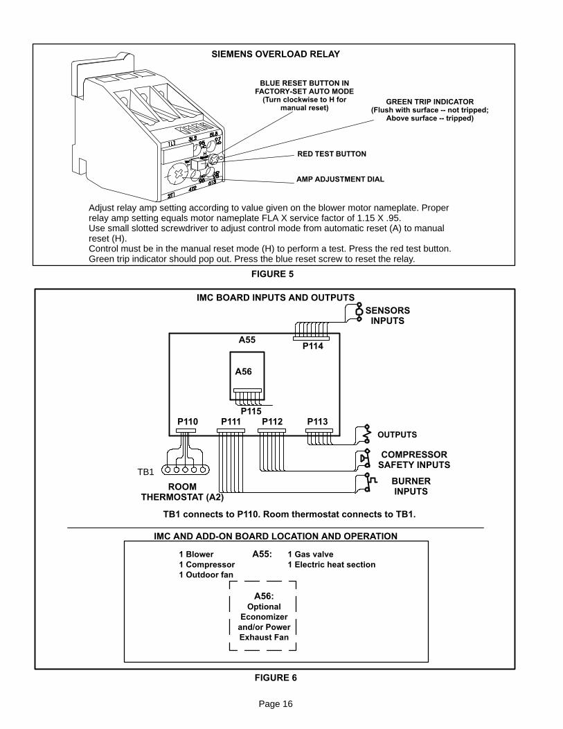
INTEGRATED MODULAR CONTROL BOARDSThe Integrated Modular Control (IMC) is a series of controlboards which integrates most control functions required for theLGA/LCA units. The control boards are located in the upperleft hand corner of the control box. The control includescomplete unit diagnostics with permanent code storage,field programmable control parameters and control op-tions, on-site testing, and serial communications. Twodifferent printed circuit boards (see figure 6) make-up themodular configurations for the LGA/LCA units. See table2 for a list of control panels used for each unit. For furtherinformation refer to Integrated Modular Control Guide sent witheach unit.
TABLE 2
UNITCONTROL PANELS
UNITA55 A56
LGA X OPT
LCA X OPT
15-Main Control Module A55 (all units)The main control module A55 is the heart of the system. Itcontrols one compressor, one single or two stage gasvalve, one bank of electric heat, one outdoor fan, and oneblower. A55 includes the thermostat inputs, serial commu-nications ports, diagnostic code display, control pushbutton,system configuration dip switches, and four expansion ports. Adiagnostic code list is located on the back side of the accesspanel.
16-Economizer Control Module A56(Economizer only)
The economizer control module A56 controls the econo-mizer. A56 has four different cooling modes, sensibletemperature, outdoor enthalpy, differential enthalpy, andglobal control.
Page 16
SIEMENS OVERLOAD RELAY
Adjust relay amp setting according to value given on the blower motor nameplate. Properrelay amp setting equals motor nameplate FLA X service factor of 1.15 X .95.Use small slotted screwdriver to adjust control mode from automatic reset (A) to manualreset (H).Control must be in the manual reset mode (H) to perform a test. Press the red test button.Green trip indicator should pop out. Press the blue reset screw to reset the relay.
BLUE RESET BUTTON INFACTORY-SET AUTO MODE
(Turn clockwise to H formanual reset)
GREEN TRIP INDICATOR(Flush with surface -- not tripped;
Above surface -- tripped)
AMP ADJUSTMENT DIAL
RED TEST BUTTON
FIGURE 5
P110 P111 P112 P113P115
SENSORSINPUTS
OUTPUTS
COMPRESSORSAFETY INPUTS
BURNERINPUTSROOM
THERMOSTAT (A2)
A55
A56
TB1 connects to P110. Room thermostat connects to TB1.
P114
IMC BOARD INPUTS AND OUTPUTS
A55:
A56:Optional
Economizerand/or PowerExhaust Fan
1 Blower1 Compressor1 Outdoor fan
1 Gas valve1 Electric heat section
IMC AND ADD-ON BOARD LOCATION AND OPERATION
FIGURE 6
TB1
Page 17
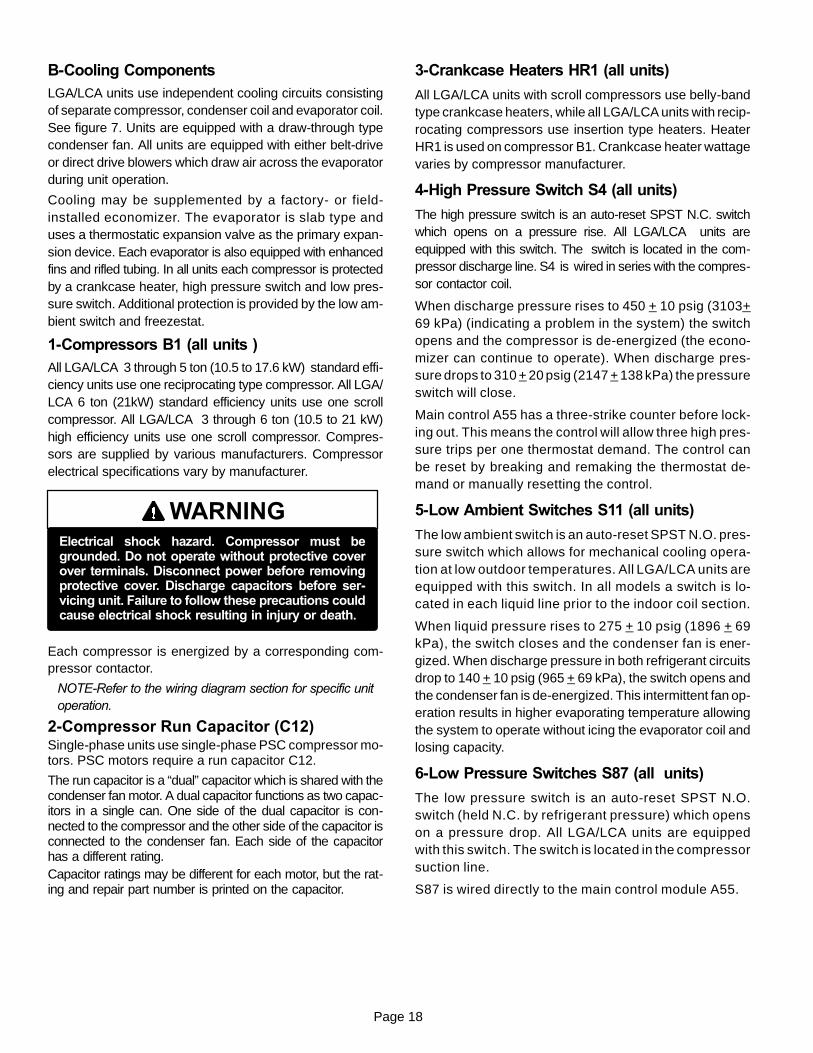
LGA/LCA PLUMBING COMPONENTS
FIGURE 7
LOW PRESSURESWITCH (S87)
SCROLL COMPRESSOR (B1)
LOW AMBIENTSWITCH (S11)
LIQUID LINESERVICE VALVE
CRANKCASE HEATER(HR1)
HIGH PRESSURESWITCH (S4)
DISCHARGE LINESERVICE VALVE
PRESSURE TAP
RECIPROCATING COMPRESSOR(B1)
LOW PRESSURESWITCH (S87)LOW AMBIENT
SWITCH (S11)
LIQUID LINESERVICE VALVE
HIGH PRESSURESWITCH (S4)
DISCHARGE LINESERVICE VALVE
PRESSURE TAP
Page 18
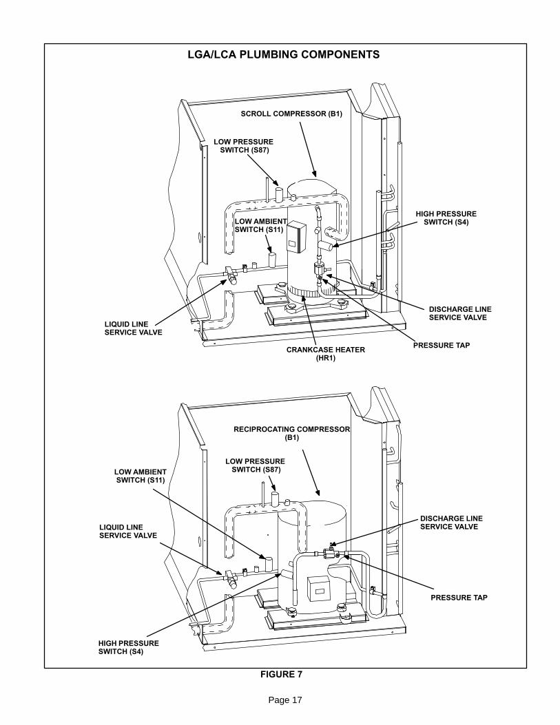
B-Cooling ComponentsLGA/LCA units use independent cooling circuits consistingof separate compressor, condenser coil and evaporator coil.See figure 7. Units are equipped with a draw-through typecondenser fan. All units are equipped with either belt-driveor direct drive blowers which draw air across the evaporatorduring unit operation.
Cooling may be supplemented by a factory- or field-installed economizer. The evaporator is slab type anduses a thermostatic expansion valve as the primary expan-sion device. Each evaporator is also equipped with enhancedfins and rifled tubing. In all units each compressor is protectedby a crankcase heater, high pressure switch and low pres-sure switch. Additional protection is provided by the low am-bient switch and freezestat.
1-Compressors B1 (all units )All LGA/LCA 3 through 5 ton (10.5 to 17.6 kW) standard effi-ciency units use one reciprocating type compressor. All LGA/LCA 6 ton (21kW) standard efficiency units use one scrollcompressor. All LGA/LCA 3 through 6 ton (10.5 to 21 kW)high efficiency units use one scroll compressor. Compres-sors are supplied by various manufacturers. Compressorelectrical specifications vary by manufacturer.
WARNINGElectrical shock hazard. Compressor must begrounded. Do not operate without protective coverover terminals. Disconnect power before removingprotective cover. Discharge capacitors before ser-vicing unit. Failure to follow these precautions couldcause electrical shock resulting in injury or death.
Each compressor is energized by a corresponding com-pressor contactor.
NOTE-Refer to the wiring diagram section for specific unitoperation.
2-Compressor Run Capacitor (C12)Single-phase units use single-phase PSC compressor mo-tors. PSC motors require a run capacitor C12.
The run capacitor is a “dual” capacitor which is shared with thecondenser fan motor. A dual capacitor functions as two capac-itors in a single can. One side of the dual capacitor is con-nected to the compressor and the other side of the capacitor isconnected to the condenser fan. Each side of the capacitorhas a different rating.Capacitor ratings may be different for each motor, but the rat-ing and repair part number is printed on the capacitor.
3-Crankcase Heaters HR1 (all units)
All LGA/LCA units with scroll compressors use belly-bandtype crankcase heaters, while all LGA/LCA units with recip-rocating compressors use insertion type heaters. HeaterHR1 is used on compressor B1. Crankcase heater wattagevaries by compressor manufacturer.
4-High Pressure Switch S4 (all units)
The high pressure switch is an auto-reset SPST N.C. switchwhich opens on a pressure rise. All LGA/LCA units areequipped with this switch. The switch is located in the com-pressor discharge line. S4 is wired in series with the compres-sor contactor coil.
When discharge pressure rises to 450 + 10 psig (3103+69 kPa) (indicating a problem in the system) the switchopens and the compressor is de-energized (the econo-mizer can continue to operate). When discharge pres-sure drops to 310 + 20 psig (2147 + 138 kPa) the pressureswitch will close.
Main control A55 has a three-strike counter before lock-ing out. This means the control will allow three high pres-sure trips per one thermostat demand. The control canbe reset by breaking and remaking the thermostat de-mand or manually resetting the control.
5-Low Ambient Switches S11 (all units)
The low ambient switch is an auto-reset SPST N.O. pres-sure switch which allows for mechanical cooling opera-tion at low outdoor temperatures. All LGA/LCA units areequipped with this switch. In all models a switch is lo-cated in each liquid line prior to the indoor coil section.
When liquid pressure rises to 275 + 10 psig (1896 + 69kPa), the switch closes and the condenser fan is ener-gized. When discharge pressure in both refrigerant circuitsdrop to 140 + 10 psig (965 + 69 kPa), the switch opens andthe condenser fan is de-energized. This intermittent fan op-eration results in higher evaporating temperature allowingthe system to operate without icing the evaporator coil andlosing capacity.
6-Low Pressure Switches S87 (all units)
The low pressure switch is an auto-reset SPST N.O.switch (held N.C. by refrigerant pressure) which openson a pressure drop. All LGA/LCA units are equippedwith this switch. The switch is located in the compressorsuction line.
S87 is wired directly to the main control module A55.
Page 19
The main control module A55 governs the low pressureswitches by shunting the switches during start up until pres-sure is stabilized. After the shunt period, the control has athree-strike counter, during first thermostat demand, before thecompressor is locked out. The control is reset by breaking andremaking the thermostat demand or manually resetting thecontrol.
When suction pressure drops to 25 + 5 psig (172 ± 34kPa) (indicating low pressure), the switch opens and thecompressor is de-energized. The switch automaticallyresets when pressure in the suction line rises to 55 + 5psig (379 ± 34 kPa).
7-Service Valves (optional on LGA/LCA units)LGA/LCA units may be equipped with service valves lo-cated in the discharge and liquid lines. The servicevalves are manually operated valves used for serviceoperation.
8-Filter Drier (all units)LGA/LCA units have a filter drier located in the liquid line ofeach refrigerant circuit upstream of the TXV in the blowercompartment. The drier removes contaminants and mois-ture from the system.
9-Freezestats S49 (all units)Each unit is equipped with a low temperature switch (freezes-tat) S49 located on a return bend of each evaporator coil.
Each freezestat is wired to the main control module A55.Each freezestat is a SPST N.C. auto-reset switch whichopens at 29°F + 3°F (-1.7°C + 1.7°C) on a temperature dropand closes at 58°F + 4°F (14.4°C + 2.2°C) on a tempera-ture rise. To prevent coil icing, freezestats open duringcompressor operation to temporarily disable the com-pressor until the coil warms sufficiently to melt any accu-mulated frost.
If the freezestat is tripping frequently due to coil icing, check theunit charge, airflow and filters before allowing unit back in op-eration. Make sure to eliminate conditions which might pro-mote evaporator ice buildup.
10-Condenser Fan B4 (all units)Refer to Specifications section of this manual for speci-fications of condenser fan B4 used in LGA/LCA units.The condenser fan used is a single-phase motor. The fanmay be removed for servicing and cleaning by removingthe fan grill.
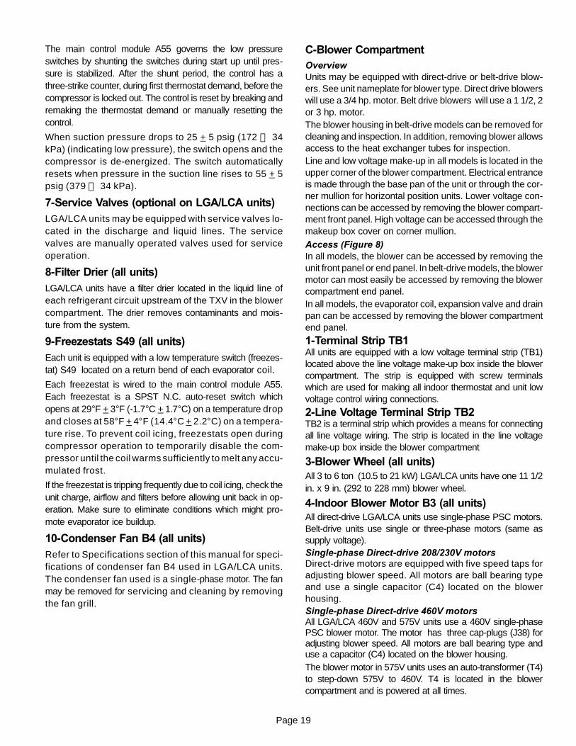
C-Blower CompartmentOverviewUnits may be equipped with direct-drive or belt-drive blow-ers. See unit nameplate for blower type. Direct drive blowerswill use a 3/4 hp. motor. Belt drive blowers will use a 1 1/2, 2or 3 hp. motor.The blower housing in belt-drive models can be removed forcleaning and inspection. In addition, removing blower allowsaccess to the heat exchanger tubes for inspection.Line and low voltage make-up in all models is located in theupper corner of the blower compartment. Electrical entranceis made through the base pan of the unit or through the cor-ner mullion for horizontal position units. Lower voltage con-nections can be accessed by removing the blower compart-ment front panel. High voltage can be accessed through themakeup box cover on corner mullion.
Access (Figure 8)In all models, the blower can be accessed by removing theunit front panel or end panel. In belt-drive models, the blowermotor can most easily be accessed by removing the blowercompartment end panel.In all models, the evaporator coil, expansion valve and drainpan can be accessed by removing the blower compartmentend panel.
1-Terminal Strip TB1All units are equipped with a low voltage terminal strip (TB1)located above the line voltage make-up box inside the blowercompartment. The strip is equipped with screw terminalswhich are used for making all indoor thermostat and unit lowvoltage control wiring connections.
2-Line Voltage Terminal Strip TB2TB2 is a terminal strip which provides a means for connectingall line voltage wiring. The strip is located in the line voltagemake-up box inside the blower compartment
3-Blower Wheel (all units)All 3 to 6 ton (10.5 to 21 kW) LGA/LCA units have one 11 1/2in. x 9 in. (292 to 228 mm) blower wheel.
4-Indoor Blower Motor B3 (all units)All direct-drive LGA/LCA units use single-phase PSC motors.Belt-drive units use single or three-phase motors (same assupply voltage).Single-phase Direct-drive 208/230V motorsDirect-drive motors are equipped with five speed taps foradjusting blower speed. All motors are ball bearing typeand use a single capacitor (C4) located on the blowerhousing.Single-phase Direct-drive 460V motorsAll LGA/LCA 460V and 575V units use a 460V single-phasePSC blower motor. The motor has three cap-plugs (J38) foradjusting blower speed. All motors are ball bearing type anduse a capacitor (C4) located on the blower housing.The blower motor in 575V units uses an auto-transformer (T4)to step-down 575V to 460V. T4 is located in the blowercompartment and is powered at all times.
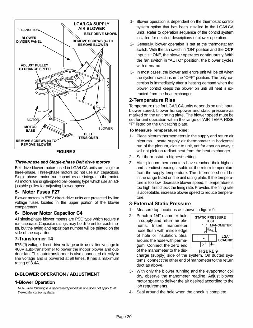
FIGURE 9
STATIC PRESSURETEST
MANOMETER
LGA/LCAUNIT
Page 20
FIGURE 8
LGA/LCA SUPPLYAIR BLOWER
BELT DRIVE SHOWNBLOWER
DIVIDER PANEL
TRANSITION
BLOWER
MOTOR
MOTORBASE
BELTTENSIONER
REMOVE SCREWS (4) TOREMOVE BLOWER
ADJUST PULLEYTO CHANGE SPEED
REMOVE SCREWS (4) TOREMOVE BLOWER
Three-phase and Single-phase Belt drive motorsBelt-drive blower motors used in LGA/LCA units are single orthree-phase. Three-phase motors do not use run capacitors.Single phase motor run capacitors are integral to the motor.All motors are single-speed ball-bearing type which use an ad-justable pulley for adjusting blower speed.
5- Motor Fuses F27Blower motors in 575V direct-drive units are protected by linevoltage fuses located in the upper portion of the blowercompartment.
6- Blower Motor Capacitor C4All single-phase blower motors are PSC type which require arun capacitor. Capacitor ratings may be different for each mo-tor, but the rating and repair part number will be printed on theside of the capacitor.
7-Transformer T4575 (J) voltage direct-drive voltage units use a line voltage to460V auto-transformer to power the indoor blower and out-door fan. This autotransformer is also connected directly toline voltage and is powered at all times. It has a maximumrating of 3.4A.
D-BLOWER OPERATION / ADJUSTMENT
1-Blower OperationNOTE-The following is a generalized procedure and does not apply to allthermostat control systems.
1- Blower operation is dependent on the thermostat controlsystem option that has been installed in the LGA/LCAunits. Refer to operation sequence of the control systeminstalled for detailed descriptions of blower operation.
2- Generally, blower operation is set at the thermostat fanswitch. With the fan switch in “ON” position and the OCPinput is “ON”, the blower operates continuously. Withthe fan switch in “AUTO” position, the blower cycleswith demand.
3- In most cases, the blower and entire unit will be off whenthe system switch is in the “OFF” position. The only ex-ception is immediately after a heating demand when theblower control keeps the blower on until all heat is ex-tracted from the heat exchanger.
2-Temperature RiseTemperature rise for LGA/LCA units depends on unit input,blower speed, blower horsepower and static pressure asmarked on the unit rating plate. The blower speed must beset for unit operation within the range of “AIR TEMP. RISE°F” listed on the unit rating plate.
To Measure Temperature Rise:1- Place plenum thermometers in the supply and return air
plenums. Locate supply air thermometer in horizontalrun of the plenum, close to unit, yet far enough away itwill not pick up radiant heat from the heat exchanger.
2- Set thermostat to highest setting.
3- After plenum thermometers have reached their highestand steadiest readings, subtract the return temperaturefrom the supply temperature. The difference should bein the range listed on the unit rating plate. If the tempera-ture is too low, decrease blower speed. If temperature istoo high, first check the firing rate. Provided the firing rateis acceptable, increase blower speed to reduce tempera-ture.
3-External Static Pressure1- Measure tap locations as shown in figure 9.
2- Punch a 1/4” diameter holein supply and return air ple-nums. Insert manometerhose flush with inside edgeof hole or insulation. Sealaround the hose with perma-gum. Connect the zero endof the manometer to the dis-charge (supply) side of the system. On ducted sys-tems, connect the other end of manometer to the returnduct as above.
3- With only the blower running and the evaporator coildry, observe the manometer reading. Adjust blowermotor speed to deliver the air desired according to thejob requirements.
4- Seal around the hole when the check is complete.
Page 21
4-Blower Speed AdjustmentTo Change Blower Speed:(208/230V Direct-Drive Units)1- Referring to blower performance tables in front of this
manual, use the static pressure and blower speed tap todetermine unit CFM.
2- Turn off electric power to unit.3- Remove blower access door.4- Disconnect blower motor harness from motor.5- Select desired speeds for heating and cooling. (Pin 6 =
Low, Pin 5 = Med-Low, Pin 4 = Medium, Pin 3 = Med-High,Pin 2 = High).
6- Depress harness connector tab to release wire terminal(J43). Select connector location for new speed (refer tounit wiring diagram). Insert wire terminal until it is securelyin place. See figure 10.
7- Replace harness connector to motor .
FIGURE 10
HARNESSCONNECTOR
MOTOR
J43
P43
BLOWER SPEED TAP SELECTION
DEPRESS TAB TO RELEASEWIRE TERMINAL. SELECTCONNECTOR LOCATIONFOR NEW SPEED (REFERTO UNIT WIRING DIAGRAM).INSERT WIRE UNTIL IT ISSECURELY IN PLACE.
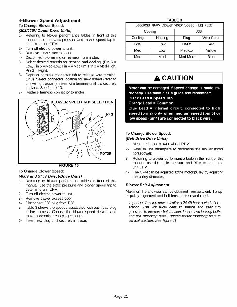
To Change Blower Speed:(460V and 575V Direct-Drive Units)1- Referring to blower performance tables in front of this
manual, use the static pressure and blower speed tap todetermine unit CFM.
2- Turn off electric power to unit.3- Remove blower access door.4- Disconnect J38 plug from P38.5- Table 3 shows the speeds associated with each cap plug
in the harness. Choose the blower speed desired andmake appropriate cap plug changes.
6- Insert new plug until securely in place.
TABLE 3Leadless 460V Blower Motor Speed Plug (J38)
Cooling J38
Cooling Heating Plug Wire Color
Low Low Lo-Lo Red
Med Low Med-Lo Yellow
Med Med Med-Med Blue
CAUTIONMotor can be damaged if speed change is made im-properly. Use table 3 as a guide and remember:Black Lead = Speed TapOrange Lead = CommonBlue Lead = Internal circuit, connected to highspeed (pin 2) only when medium speed (pin 3) orlow speed (pin4) are connected to black wire.
To Change Blower Speed:(Belt Drive Drive Units)1- Measure indoor blower wheel RPM.2- Refer to unit nameplate to determine the blower motor
horsepower.3- Referring to blower performance table in the front of this
manual, use the static pressure and RPM to determineunit CFM.
4- The CFM can be adjusted at the motor pulley by adjustingthe pulley diameter.
Blower Belt Adjustment
Maximum life and wear can be obtained from belts only if prop-er pulley alignment and belt tension are maintained.
Important-Tension new belt after a 24-48 hour period of op-eration. This will allow belts to stretch and seat intogrooves. To increase belt tension, loosen two locking boltsand pull mounting plate. Tighten motor mounting plate invertical position. See figure 11.

Page 22
FIGURE 11
BLOWER SPEED ADJUSTMENT
BLOWER PULLEY
MOTORPULLEY
SET SCREW
KEYBLOWER
TO INCREASE CFMTURN PULLEY CLOCKWISE
TO DECREASE CFMTURN PULLEYCOUNTERCLOCKWISE
MOTORMOUNTING PLATE LOCKING BOLTS
(2-TOP & BOTTOM)
TO INCREASE BELT TENSION1 - Loosen 2 locking bolts.2 - Pull motor mounting plate.3 - Tighten motor mounting
plate so plate is vertical.
Check Belt Tension
Overtensioning belts shortens belt and bearing life. Checkbelt tension as follows:
1- Measure span length X. See figure 12.
2- Apply perpendicular force to center of span (X) withenough pressure to deflect belt 1/64” for every inch ofspan length or 1.5mm per 100mm of span length.
Example: Deflection distance of a 40” span would be40/64” or 5/8”.
Example: Deflection distance of a 400mm span wouldbe 6mm.
3- Measure belt deflection force. For a used belt, thedeflection force should be 5 lbs. (35kPa). A new beltdeflection force should be 7 lbs. (48kPa).
A force below these values indicates and underten-sioned belt. A force above these values indicates anovertensioned belt.
MEASURE BELT TENSION
DEFLECTION 1/64” PER INCH OF SPANOR 1.5mm PER 100mm OF SPAN
FORCE
FIGURE 12
Page 23
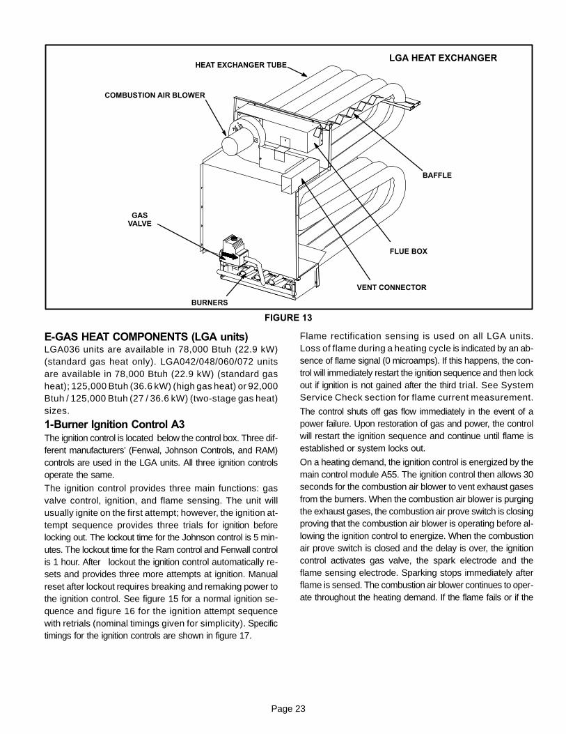
FIGURE 13
FLUE BOX
VENT CONNECTOR
BAFFLE
HEAT EXCHANGER TUBE
COMBUSTION AIR BLOWER
GASVALVE
BURNERS
LGA HEAT EXCHANGER
E-GAS HEAT COMPONENTS (LGA units)LGA036 units are available in 78,000 Btuh (22.9 kW)(standard gas heat only). LGA042/048/060/072 unitsare available in 78,000 Btuh (22.9 kW) (standard gasheat); 125,000 Btuh (36.6 kW) (high gas heat) or 92,000Btuh / 125,000 Btuh (27 / 36.6 kW) (two-stage gas heat)sizes.
1-Burner Ignition Control A3The ignition control is located below the control box. Three dif-ferent manufacturers’ (Fenwal, Johnson Controls, and RAM)controls are used in the LGA units. All three ignition controlsoperate the same.
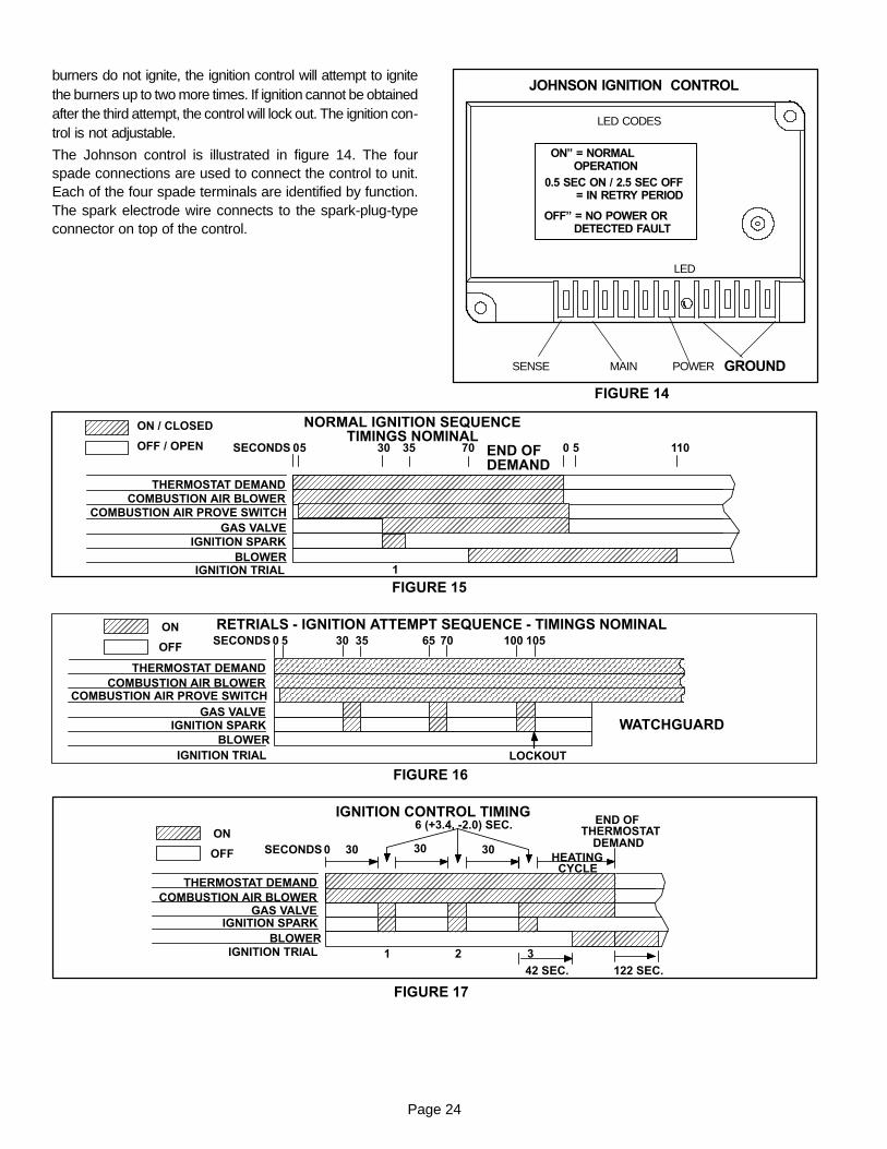
The ignition control provides three main functions: gasvalve control, ignition, and flame sensing. The unit willusually ignite on the first attempt; however, the ignition at-tempt sequence provides three trials for ignition beforelocking out. The lockout time for the Johnson control is 5 min-utes. The lockout time for the Ram control and Fenwall controlis 1 hour. After lockout the ignition control automatically re-sets and provides three more attempts at ignition. Manualreset after lockout requires breaking and remaking power tothe ignition control. See figure 15 for a normal ignition se-quence and figure 16 for the ignition attempt sequencewith retrials (nominal timings given for simplicity). Specifictimings for the ignition controls are shown in figure 17.
Flame rectification sensing is used on all LGA units.Loss of flame during a heating cycle is indicated by an ab-sence of flame signal (0 microamps). If this happens, the con-trol will immediately restart the ignition sequence and then lockout if ignition is not gained after the third trial. See SystemService Check section for flame current measurement.
The control shuts off gas flow immediately in the event of apower failure. Upon restoration of gas and power, the controlwill restart the ignition sequence and continue until flame isestablished or system locks out.
On a heating demand, the ignition control is energized by themain control module A55. The ignition control then allows 30seconds for the combustion air blower to vent exhaust gasesfrom the burners. When the combustion air blower is purgingthe exhaust gases, the combustion air prove switch is closingproving that the combustion air blower is operating before al-lowing the ignition control to energize. When the combustionair prove switch is closed and the delay is over, the ignitioncontrol activates gas valve, the spark electrode and theflame sensing electrode. Sparking stops immediately afterflame is sensed. The combustion air blower continues to oper-ate throughout the heating demand. If the flame fails or if the
Page 24
burners do not ignite, the ignition control will attempt to ignitethe burners up to two more times. If ignition cannot be obtainedafter the third attempt, the control will lock out. The ignition con-trol is not adjustable.
The Johnson control is illustrated in figure 14. The fourspade connections are used to connect the control to unit.Each of the four spade terminals are identified by function.The spark electrode wire connects to the spark-plug-typeconnector on top of the control.
FIGURE 14
JOHNSON IGNITION CONTROL
LED CODES
ON” = NORMALOPERATION
0.5 SEC ON / 2.5 SEC OFF= IN RETRY PERIOD
OFF” = NO POWER ORDETECTED FAULT
GROUND
LED
POWERMAINSENSE
NORMAL IGNITION SEQUENCETIMINGS NOMINAL
THERMOSTAT DEMANDCOMBUSTION AIR BLOWER
GAS VALVEIGNITION SPARK
BLOWERIGNITION TRIAL
SECONDS 0 30 35 0 110
ON / CLOSED
OFF / OPEN END OFDEMAND
1
COMBUSTION AIR PROVE SWITCH
5 570
FIGURE 15
FIGURE 16
RETRIALS - IGNITION ATTEMPT SEQUENCE - TIMINGS NOMINAL
THERMOSTAT DEMANDCOMBUSTION AIR BLOWER
GAS VALVEIGNITION SPARK
BLOWERIGNITION TRIAL
SECONDS 0 30 35 70ON
OFF 65 100 105
WATCHGUARD
LOCKOUT
COMBUSTION AIR PROVE SWITCH
5
FIGURE 17
THERMOSTAT DEMANDCOMBUSTION AIR BLOWER
GAS VALVEIGNITION SPARK
BLOWERIGNITION TRIAL
SECONDS 0 30ON
OFF
IGNITION CONTROL TIMING
30 30HEATING
CYCLE
6 (+3.4, -2.0) SEC. END OFTHERMOSTAT
DEMAND
1 2 3
42 SEC. 122 SEC.
Page 25
WARNINGSHOCK HAZARD. SPARK RELATED COMPONENTSCONTAIN HIGH VOLTAGE WHICH CAN CAUSEPERSONAL INJURY OR DEATH. DISCONNECTPOWER BEFORE SERVICING. CONTROL IS NOTFIELD REPAIRABLE. UNSAFE OPERATION WILLRESULT. IF THE CONTROL IS INOPERABLE, SIM-PLY REPLACE THE ENTIRE CONTROL.
2-Heat Exchanger (Figure 13)The LGA units use aluminized steel inshot burners with match-ing tubular aluminized or optional stainless steel heat ex-changers and either a one or two-stage redundant gas valve.LGA uses one five tube/burners for high heat and one threetube/burners for low heat. Each burner uses a burner venturi tomix gas and air for proper combustion. Combustion takesplace at each tube entrance. As hot combustion gases aredrawn upward through each tube by the combustion air blow-er, exhaust gases are drawn out the top and fresh air/gas mix-ture is drawn in at the bottom. Heat is transferred to the airstream from all surfaces of the heat exchanger tubes. Thesupply air blowers, controlled by the main control panel A55,force air across all surfaces of the tubes to extract the heat ofcombustion. The shape of the tubes ensures maximum heatexchange.
The gas valve accomplishes staging by allowing more or lessgas to the burners as called for by heating demand.
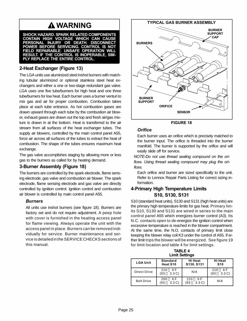
3-Burner Assembly (Figure 18)The burners are controlled by the spark electrode, flame sens-ing electrode, gas valve and combustion air blower. The sparkelectrode, flame sensing electrode and gas valve are directlycontrolled by ignition control. Ignition control and combustionair blower is controlled by main control panel A55.
BurnersAll units use inshot burners (see figure 18). Burners arefactory set and do not require adjustment. A peep holewith cover is furnished in the heating access panelfor flame viewing. Always operate the unit with theaccess panel in place. Burners can be removed indi-vidually for service. Burner maintenance and ser-vice is detailed in the SERVICE CHECKS sections ofthis manual.
FIGURE 18
TYPICAL GAS BURNER ASSEMBLY
BURNERS
ORIFICE
SENSOR
BURNERSUPPORT
BURNERSUPPORT
CAP
OrificeEach burner uses an orifice which is precisely matched tothe burner input. The orifice is threaded into the burnermanifold. The burner is supported by the orifice and willeasily slide off for service.
NOTE-Do not use thread sealing compound on the ori-fices. Using thread sealing compound may plug the ori-fices.
Each orifice and burner are sized specifically to the unit.Refer to Lennox Repair Parts Listing for correct sizing in-formation.
4-Primary High Temperature LimitsS10, S130, S131
S10 (standard heat units), S130 and S131 (high heat units) arethe primary high temperature limits for gas heat. Primary lim-its S10, S130 and S131 are wired in series to the maincontrol panel A55 which energizes burner control (A3). ItsN.C. contacts open to de-energize the ignition control whenexcessive temperature is reached in the blower compartment.At the same time, the N.O. contacts of primary limit closekeeping the blower relay coil K3 under the control of A55. If ei-ther limit trips the blower will be energized. See figure 19for limit location and table 4 for limit settings.
TABLE 4Limit Settings
LGA UnitStandardHeat S10
Hi HeatS130, S131
Hi HeatS10
Direct Drive210 ± 6 F
(93 ± 3.3 C) N/A210 ± 6 F
(93 ± 3.3 C)
Belt Drive200 ± 6 F
(93 ± 3.3 C)210 ± 6 F
(93 ± 3.3 C) N/A
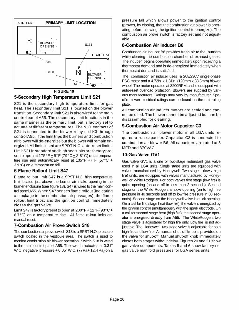
Page 26
FIGURE 19
BLOWEROPENING
BLOWEROPENING
S10
S131
S130
PRIMARY LIMIT LOCATION
5-Secondary High Temperature Limit S21S21 is the secondary high temperature limit for gasheat. The secondary limit S21 is located on the blowertransition. Secondary limit S21 is also wired to the maincontrol panel A55. The secondary limit functions in thesame manner as the primary limit, but is factory set toactuate at different temperatures. The N.O. contacts ofS21 is connected to the blower relay coil K3 throughcontrol A55. If the limit trips the burners and combustionair blower will de-energize but the blower will remain en-ergized. All limits used are SPDT N.C. auto-reset limits.Limit S21 in standard and high heat units are factory pre-set to open at 175_F + 5_F (79_C + 2.8_C) on a tempera-ture rise and automatically reset at 135_F +7_F (57_C +3.9_C) on a temperature fall.
6-Flame Rollout Limit S47Flame rollout limit S47 is a SPST N.C. high temperaturelimit located just above the burner air intake opening in theburner enclosure (see figure 13). S47 is wired to the main con-trol panel A55. When S47 senses flame rollout (indicatinga blockage in the combustion air passages), the flamerollout limit trips, and the ignition control immediatelycloses the gas valve.Limit S47 is factory preset to open at 200_F + 12_F (93_C +6.7_C) on a temperature rise. All flame rollout limits aremanual reset.
7-Combustion Air Prove Switch S18The combustion air prove switch S18 is a SPST N.O. pressureswitch located in the vestibule area. The switch is used tomonitor combustion air blower operation. Switch S18 is wiredto the main control panel A55. The switch actuates at 0.31”W.C. negative pressure + 0.05” W.C. (77Pa+ 12.4 Pa) on a
pressure fall which allows power to the ignition control(proves, by closing, that the combustion air blower is oper-ating before allowing the ignition control to energize). Thecombustion air prove switch is factory set and not adjust-able.
8-Combustion Air Inducer B6Combustion air inducer B6 provides fresh air to the burnerswhile clearing the combustion chamber of exhaust gases.The inducer begins operating immediately upon receiving athermostat demand and is de-energized immediately whenthermostat demand is satisfied.
The combustion air inducer uses a 208/230V single-phasePSC motor and a 4.72in. x 1.31in. (120mm x 33.3mm) blowerwheel. The motor operates at 3200RPM and is equipped withauto-reset overload protection. Blowers are supplied by vari-ous manufacturers. Ratings may vary by manufacturer. Spe-cific blower electrical ratings can be found on the unit ratingplate.
All combustion air inducer motors are sealed and can-not be oiled. The blower cannot be adjusted but can bedisassembled for cleaning.
9-Combustion Air Motor Capacitor C3The combustion air blower motor in all LGA units re-quires a run capacitor. Capacitor C3 is connected tocombustion air blower B6. All capacitors are rated at 3MFD and 370VAC.
10-Gas Valve GV1Gas valve GV1 is a one or two-stage redundant gas valveused in all LGA units. Single stage units are equipped withvalves manufactured by Honeywell. Two-stage (low / highfire) units, are equipped with valves manufactured by Honey-well or White Rodgers. For both valves first stage (low fire) isquick opening (on and off in less than 3 seconds). Secondstage on the White Rodgers is slow opening (on to high firepressure in 40 seconds and off to low fire pressure in 30 sec-onds). Second stage on the Honeywell valve is quick opening.On a call for first stage heat (low fire), the valve is energized bythe ignition control simultaneously with the spark electrode. Ona call for second stage heat (high fire), the second stage oper-ator is energized directly from A55. The WhiteRodgers twostage valve is adjustabel for high fire only. Low fire is not ad-justable. The Honeywell two stage valve is adjustable for bothhigh fire and low fire. A manual shut-off knob is provided onthe valve for shut-off. Manual shut-off knob immediatelycloses both stages without delay. Figures 20 and 21 showgas valve components. Tables 5 and 6 show factory setgas valve manifold pressures for LGA series units.
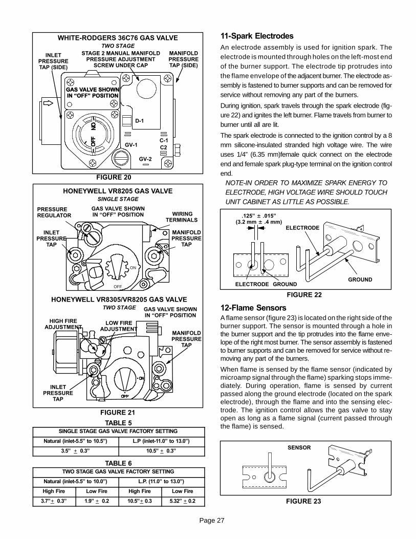
Page 27
FIGURE 20
WHITE-RODGERS 36C76 GAS VALVETWO STAGE
D-1
GV-1C-1C2
GV-2
MANIFOLDPRESSURETAP (SIDE)
STAGE 2 MANUAL MANIFOLDPRESSURE ADJUSTMENT
SCREW UNDER CAP
INLETPRESSURETAP (SIDE)
GAS VALVE SHOWNIN “OFF” POSITIONGAS VALVE SHOWNIN “OFF” POSITION
FIGURE 21
HONEYWELL VR8205 GAS VALVESINGLE STAGE
ON
OFF
PRESSUREREGULATOR
INLETPRESSURE
TAP
WIRINGTERMINALS
LOW FIREADJUSTMENT
HIGH FIREADJUSTMENT
INLETPRESSURE
TAP
MANIFOLDPRESSURE
TAP
HONEYWELL VR8305/VR8205 GAS VALVETWO STAGE
MANIFOLDPRESSURE
TAP
GAS VALVE SHOWNIN “OFF” POSITION
GAS VALVE SHOWNIN “OFF” POSITION
TABLE 5SINGLE STAGE GAS VALVE FACTORY SETTING
Natural (inlet-5.5” to 10.5”) L.P (inlet-11.0” to 13.0”)
3.5” + 0.3” 10.5” + 0.3”
TABLE 6TWO STAGE GAS VALVE FACTORY SETTING
Natural (inlet-5.5” to 10.0”) L.P. (11.0” to 13.0”)
High Fire Low Fire High Fire Low Fire
3.7”+ 0.3” 1.9” + 0.2 10.5”+ 0.3 5.32” + 0.2
11-Spark ElectrodesAn electrode assembly is used for ignition spark. Theelectrode is mounted through holes on the left-most endof the burner support. The electrode tip protrudes intothe flame envelope of the adjacent burner. The electrode as-sembly is fastened to burner supports and can be removed forservice without removing any part of the burners.
During ignition, spark travels through the spark electrode (fig-ure 22) and ignites the left burner. Flame travels from burner toburner until all are lit.
The spark electrode is connected to the ignition control by a 8mm silicone-insulated stranded high voltage wire. The wireuses 1/4” (6.35 mm)female quick connect on the electrodeend and female spark plug-type terminal on the ignition controlend.
NOTE-IN ORDER TO MAXIMIZE SPARK ENERGY TOELECTRODE, HIGH VOLTAGE WIRE SHOULD TOUCHUNIT CABINET AS LITTLE AS POSSIBLE.
GROUND
ELECTRODE
GROUNDELECTRODE
.125” ± .015”(3.2 mm ± .4 mm)
FIGURE 22
12-Flame SensorsA flame sensor (figure 23) is located on the right side of theburner support. The sensor is mounted through a hole inthe burner support and the tip protrudes into the flame enve-lope of the right most burner. The sensor assembly is fastenedto burner supports and can be removed for service without re-moving any part of the burners.
When flame is sensed by the flame sensor (indicated bymicroamp signal through the flame) sparking stops imme-diately. During operation, flame is sensed by currentpassed along the ground electrode (located on the sparkelectrode), through the flame and into the sensing elec-trode. The ignition control allows the gas valve to stayopen as long as a flame signal (current passed throughthe flame) is sensed.
SENSOR
FIGURE 23
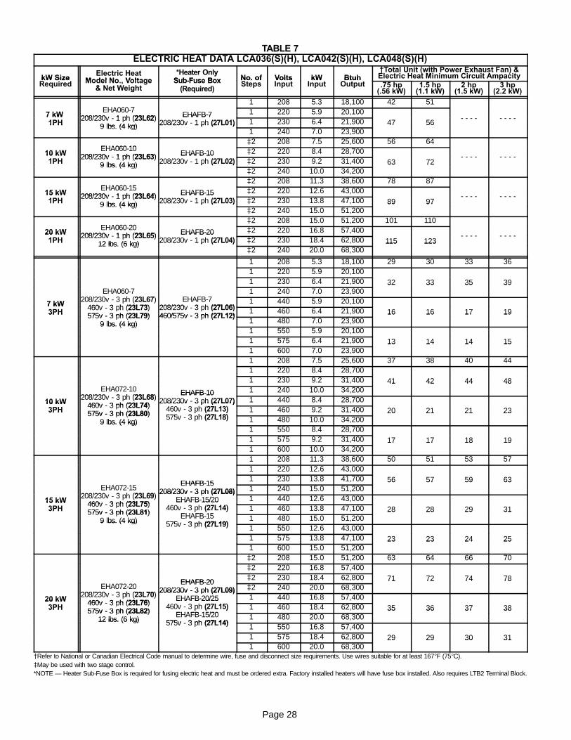
Page 28
TABLE 7ELECTRIC HEAT DATA LCA036(S)(H), LCA042(S)(H), LCA048(S)(H)
kW SizeRequired
Electric HeatModel No., Voltage
*Heater OnlySub-Fuse Box No. of
StepsVoltsInput
kWInput
BtuhOutput
{{Total Unit (with Power Exhaust Fan) &Electric Heat Minimum Circuit AmpacitykW Size
Required Model No., Voltage& Net Weight
Sub-Fuse Box(Required)
No. ofSteps
VoltsInput
kWInput
BtuhOutput .75 hp
(.56 kW)1.5 hp
(1.1 kW)2 hp
(1.5 kW)3 hp
(2.2 kW)
EHA060-71 208 5.3 18,100 42 51
7 kWEHA060-7
208/230v - 1 ph (23L62) EHAFB-7 1 220 5.9 20,100- - - - - - - -7 kW
1PH208/230v - 1 ph (23L62)
9 lbs. (4 kg)
EHAFB-7208/230v - 1 ph (27L01) 1 230 6.4 21,900 47 56
- - - - - - - -1PH 9 lbs. (4 kg) 208/230v - 1 ph (27L01)
1 240 7.0 23,90047 56
EHA060-10}2 208 7.5 25,600 56 64
10 kW1PH
EHA060-10208/230v - 1 ph (23L63) EHAFB-10
(27L02)}2 220 8.4 28,700
- - - - - - - -10 kW1PH
208/230v - 1 ph (23L63)9 lbs. (4 kg)
EHAFB-10208/230v - 1 ph (27L02) }2 230 9.2 31,400 63 72
- - - - - - - -1PH 9 lbs. (4 kg) 208/230v - 1 ph (27L02)
}2 240 10.0 34,20063 72
EHA060-15}2 208 11.3 38,600 78 87
15 kW1PH
EHA060-15208/230v - 1 ph (23L64) EHAFB-15
(27L03)}2 220 12.6 43,000
- - - - - - - -15 kW1PH
208/230v - 1 ph (23L64)9 lbs. (4 kg)
EHAFB-15208/230v - 1 ph (27L03) }2 230 13.8 47,100 89 97
- - - - - - - -1PH 9 lbs. (4 kg) 208/230v - 1 ph (27L03)
}2 240 15.0 51,20089 97
EHA060-20}2 208 15.0 51,200 101 110
20 kW1PH
EHA060-20208/230v - 1 ph (23L65) EHAFB-20
(27L04)}2 220 16.8 57,400
- - - - - - - -20 kW1PH
208/230v - 1 ph (23L65)12 lbs. (6 kg)
EHAFB-20208/230v - 1 ph (27L04) }2 230 18.4 62,800 115 123
- - - - - - - -1PH 12 lbs. (6 kg) 208/230v - 1 ph (27L04)
}2 240 20.0 68,300115 123
1 208 5.3 18,100 29 30 33 361 220 5.9 20,1001 230 6.4 21,900 32 33 35 39
EHA060-7208/230v - 3 ph (23L67) EHAFB-7
1 240 7.0 23,90032 33 35 39
7 kW
EHA060-7208/230v - 3 ph (23L67)
460v - 3 ph (23L73)EHAFB-7
208/230v - 3 ph (27L06)1 440 5.9 20,1007 kW
3PH460v - 3 ph (23L73)575v - 3 ph (23L79)
208/230v - 3 ph (27L06)460/575v - 3 ph (27L12)
1 460 6.4 21,900 16 16 17 193PH 575v - 3 ph (23L79)9 lbs. (4 kg)
460/575v - 3 ph (27L12)1 480 7.0 23,900
16 16 17 19
9 lbs. (4 kg)1 550 5.9 20,1001 575 6.4 21,900 13 14 14 151 600 7.0 23,900
13 14 14 15
1 208 7.5 25,600 37 38 40 441 220 8.4 28,700
EHA072-101 230 9.2 31,400 41 42 44 48
EHA072-10208/230v - 3 ph (23L68)
EHAFB-10 1 240 10.0 34,20041 42 44 48
10 kW3PH
EHA072-10208/230v - 3 ph (23L68)
460v - 3 ph (23L74)
EHAFB-10208/230v - 3 ph (27L07)
460v - 3 ph (27L13)1 440 8.4 28,70010 kW
3PH460v - 3 ph (23L74)575v - 3 ph (23L80)
208/230v - 3 ph (27L07)460v - 3 ph (27L13)575v - 3 ph (27L18)
1 460 9.2 31,400 20 21 21 233PH 575v - 3 ph (23L80)9 lbs. (4 kg)
460v - 3 ph (27L13)575v - 3 ph (27L18) 1 480 10.0 34,200
20 21 21 23
9 lbs. (4 kg)1 550 8.4 28,7001 575 9.2 31,400 17 17 18 191 600 10.0 34,200
17 17 18 19
1 208 11.3 38,600 50 51 53 571 220 12.6 43,000
EHA072-15EHAFB-15
1 230 13.8 41,700 56 57 59 63EHA072-15
208/230v - 3 ph (23L69)
EHAFB-15208/230v - 3 ph (27L08) 1 240 15.0 51,200
56 57 59 63
15 kW3PH
EHA072-15208/230v - 3 ph (23L69)
460v - 3 ph (23L75)
208/230v - 3 ph (27L08)EHAFB-15/20
460v - 3 ph (27L14)1 440 12.6 43,00015 kW
3PH460v - 3 ph (23L75)575v - 3 ph (23L81)
EHAFB-15/20460v - 3 ph (27L14)
EHAFB-151 460 13.8 47,100 28 28 29 313PH 575v - 3 ph (23L81)
9 lbs. (4 kg)
460v - 3 ph (27L14)EHAFB-15
575v - 3 ph (27L19)1 480 15.0 51,200
28 28 29 31
9 lbs. (4 kg) 575v - 3 ph (27L19) 1 550 12.6 43,0001 575 13.8 47,100 23 23 24 251 600 15.0 51,200
23 23 24 25
}2 208 15.0 51,200 63 64 66 70}2 220 16.8 57,400
EHA072-20EHAFB-20
}2 230 18.4 62,800 71 72 74 78EHA072-20
208/230v - 3 ph (23L70)
EHAFB-20208/230v - 3 ph (27L09) }2 240 20.0 68,300
71 72 74 78
20 kW3PH
EHA072-20208/230v - 3 ph (23L70)
460v - 3 ph (23L76)
208/230v - 3 ph (27L09)EHAFB-20/25
460v - 3 ph (27L15)1 440 16.8 57,40020 kW
3PH460v - 3 ph (23L76)575v - 3 ph (23L82)
EHAFB-20/25460v - 3 ph (27L15)
EHAFB-15/201 460 18.4 62,800 35 36 37 383PH 575v - 3 ph (23L82)
12 lbs. (6 kg)
460v - 3 ph (27L15)EHAFB-15/20
575v - 3 ph (27L14)1 480 20.0 68,300
35 36 37 38
12 lbs. (6 kg) 575v - 3 ph (27L14) 1 550 16.8 57,4001 575 18.4 62,800 29 29 30 311 600 20.0 68,300
29 29 30 31
{Refer to National or Canadian Electrical Code manual to determine wire, fuse and disconnect size requirements. Use wires suitable for at least 167°F (75°C).}May be used with two stage control.*NOTE — Heater Sub-Fuse Box is required for fusing electric heat and must be ordered extra. Factory installed heaters will have fuse box installed. Also requires LTB2 Terminal Block.

Page 29
TABLE 8ELECTRIC HEAT DATA LCA060(S)(H)
kW SizeRequired
Electric HeatModel No., Voltage
*Heater OnlySub-Fuse Box No. of
StepsVoltsInput
kWInput
BtuhOutput
{{Total Unit (with Power Exhaust Fan) &Electric Heat Minimum Circuit AmpacitykW Size
Required Model No., Voltage& Net Weight
Sub-Fuse Box(Required)
No. ofSteps
VoltsInput
kWInput
BtuhOutput .75 hp
(.56 kW)1.5 hp
(1.1 kW)2 hp
(1.5 kW)3 hp
(2.2 kW)
EHA060-71 208 5.3 18,100
7 kW EHA060-7208/230v - 1 ph (23L62) EHAFB-7 1 220 5.9 20,100
48 56 - - - - - - - -7 kW1PH
EHA060-7208/230v - 1 ph (23L62)
9 lbs. (4 kg)
EHAFB-7208/230v - 1 ph (27L01) 1 230 6.4 21,900 48 56 - - - - - - - -1PH 208/230v - 1 ph (23L62)
9 lbs. (4 kg) 208/230v - 1 ph (27L01)1 240 7.0 23,900
48 56 - - - - - - - -
10 kW EHA060-10 EHAFB-10}2 208 7.5 25,600 56 64
10 kW1PH
EHA060-10208/230v - 1 ph (23L63) EHAFB-10
208/230v - 1 ph (27L02)}2 220 8.4 28,700 - - - - - - - -
10 kW1PH 208/230v - 1 ph (23L63)
9 lbs. (4 kg)
EHAFB-10208/230v - 1 ph (27L02) }2 230 9.2 31,400 63 72
- - - - - - - -1PH 9 lbs. (4 kg) 208/230v - 1 ph (27L02)}2 240 10.0 34,200
63 72
15 kW EHA060-15 EHAFB-15}2 208 11.3 38,600 78 87
15 kW1PH
EHA060-15208/230v - 1 ph (23L64) EHAFB-15
208/230v - 1 ph (27L03)}2 220 12.6 43,000 - - - - - - - -
15 kW1PH 208/230v - 1 ph (23L64)
9 lbs. (4 kg)
EHAFB-15208/230v - 1 ph (27L03) }2 230 13.8 47,100 89 97
- - - - - - - -1PH 9 lbs. (4 kg) 208/230v - 1 ph (27L03)}2 240 15.0 51,200
89 97
20 kW EHA060-20 EHAFB-20}2 208 15.0 51,200 101 110
20 kW1PH
EHA060-20208/230v - 1 ph (23L65) EHAFB-20
208/230v - 1 ph (27L04)}2 220 16.8 57,400 - - - - - - - -
20 kW1PH 208/230v - 1 ph (23L65)
12 lbs. (6 kg)
EHAFB-20208/230v - 1 ph (27L04) }2 230 18.4 62,800 115 123
- - - - - - - -1PH 12 lbs. (6 kg) 208/230v - 1 ph (27L04)}2 240 20.0 68,300
115 123
25 kW EHA060-25 EHAFB-25}2 208 18.8 64,200 123 132
25 kW1PH
EHA060-25208/230v - 1 ph (23L66) EHAFB-25
208/230v - 1 ph (27L05)}2 220 21.0 71,700 - - - - - - - -
25 kW1PH 208/230v - 1 ph (23L66)
12 lbs. (6 kg)
EHAFB-25208/230v - 1 ph (27L05) }2 230 23.0 78,500 141 149
- - - - - - - -1PH 12 lbs. (6 kg) 208/230v - 1 ph (27L05)}2 240 25.0 85,400
141 149
1 208 5.3 18,1001 220 5.9 20,100 34(H) 35(H) 36(H) 40(H)
EHA060-71 230 6.4 21,900
34(H)33(S)
35(H)34(S)
36(H)35(S)
40(H)39(S)
EHA060-7208/230v - 3 ph (23L67) EHAFB-7
1 240 7.0 23,90033(S) 34(S) 35(S) 39(S)
7 kW
EHA060-7208/230v - 3 ph (23L67)
460v - 3 ph (23L73)EHAFB-7
208/230v - 3 ph (27L06)1 440 5.9 20,100 18(H) 20(H)7 kW
3PH
208/230v - 3 ph (23L67)460v - 3 ph (23L73)575v - 3 ph (23L79)
EHAFB-7208/230v - 3 ph (27L06)460/575v - 3 ph (27L12)
1 460 6.4 21,900 1718(H)17(S) 18
20(H)19(S)
7 kW3PH
460v - 3 ph (23L73)575v - 3 ph (23L79)
9 lbs. (4 kg)
208/230v - 3 ph (27L06)460/575v - 3 ph (27L12) 1 480 7.0 23,900
17 17(S) 18 19(S)3PH9 lbs. (4 kg)
460/575v - 3 ph (27L12)
1 550 5.9 20,100 14(H) 15(H) 16(H)1 575 6.4 21,900
14(H)13(S) 14
15(H)14(S)
16(H)15(S)
1 600 7.0 23,90013(S) 14 14(S) 15(S)
1 208 7.5 25,600 37 38 40 441 220 8.4 28,700
EHA072-101 230 9.2 31,400 41 42 44 48
10 kW
EHA072-10208/230v - 3 ph (23L68) EHAFB-10
208/230v - 3 ph (27L07)1 240 10.0 34,200
41 42 44 48
10 kW3PH
208/230v - 3 ph (23L68)460v - 3 ph (23L74)
EHAFB-10208/230v - 3 ph (27L07)
460v - 3 ph (27L13)1 440 8.4 28,70010 kW
3PH 460v - 3 ph (23L74)575v - 3 ph (23L80)
208/230v - 3 ph (27L07)460v - 3 ph (27L13)575v - 3 ph (27L18)
1 460 9.2 31,400 20 21 21 233PH 575v - 3 ph (23L80)9 lbs. (4 kg)
460v - 3 ph (27L13)575v - 3 ph (27L18) 1 480 10.0 34,200
20 21 21 239 lbs. (4 kg) 575v - 3 ph (27L18)
1 550 8.4 28,7001 575 9.2 31,400 17 17 18 191 600 10.0 34,200
17 17 18 19
1 208 11.3 38,600 50 51 53 571 220 12.6 43,000
EHA072-15 EHAFB-15 1 230 13.8 47,100 56 57 59 63
15 kW
EHA072-15208/230v - 3 ph (23L69)
EHAFB-15208/230v - 3 ph (27L08)
EHAFB-15/201 240 15.0 51,200
56 57 59 63
15 kW3PH
208/230v - 3 ph (23L69)460v - 3 ph (23L75)
208/230v - 3 ph (27L08)EHAFB-15/20
460v - 3 ph (27L14)1 440 12.6 43,00015 kW
3PH 460v - 3 ph (23L75)575v - 3 ph (23L81)
EHAFB-15/20460v - 3 ph (27L14)
EHAFB-151 460 13.8 47,100 28 28 29 313PH 575v - 3 ph (23L81)
9 lbs. (4 kg)
460v - 3 ph (27L14)EHAFB-15
575v - 3 ph (27L19)1 480 15.0 51,200
28 28 29 319 lbs. (4 kg) EHAFB-15
575v - 3 ph (27L19) 1 550 12.6 43,000575v - 3 ph (27L19)1 575 13.8 47,100 23 23 24 251 600 15.0 51,200
23 23 24 25
}2 208 15.0 51,200 63 64 66 70}2 220 16.8 57,400
EHA072-20 EHAFB-20 }2 230 18.4 62,800 71 72 74 78
20 kW
EHA072-20208/230v - 3 ph (23L70)
EHAFB-20208/230v - 3 ph (27L09)
EHAFB-20/25}2 240 20.0 68,300
71 72 74 78
20 kW3PH
208/230v - 3 ph (23L70)460v - 3 ph (23L76)
208/230v - 3 ph (27L09)EHAFB-20/25
460v - 3 ph (27L15)1 440 16.8 57,40020 kW
3PH 460v - 3 ph (23L76)575v - 3 ph (23L82)
EHAFB-20/25460v - 3 ph (27L15)
EHAFB-15/201 460 18.4 62,800 35 36 37 383PH 575v - 3 ph (23L82)
12 lbs. (6 kg)
460v - 3 ph (27L15)EHAFB-15/20
575v - 3 ph (27L14)1 480 20.0 68,300
35 36 37 3812 lbs. (6 kg) EHAFB-15/20
575v - 3 ph (27L14) 1 550 16.8 57,400575v - 3 ph (27L14)1 575 18.4 62,800 29 29 30 311 600 20.0 68,300
29 29 30 31
}2 208 18.8 64,200 76 77 79 83}2 220 21.0 71,700
EHA072-25 EHAFB-25 }2 230 23.0 78,500 86 87 89 93
25 kW
EHA072-25208/230v - 3 ph (23L71)
EHAFB-25208/230v - 3 ph (27L10)
EHAFB-25/30}2 240 25.0 85,400
86 87 89 93
25 kW3PH
208/230v - 3 ph (23L71)460v - 3 ph (23L77)
208/230v - 3 ph (27L10)EHAFB-25/30
460v - 3 ph (27L16)1 440 21.0 71,70025 kW
3PH 460v - 3 ph (23L77)575v - 3 ph (23L83)
EHAFB-25/30460v - 3 ph (27L16)
EHAFB-20/251 460 23.0 78,500 43 43 44 463PH 575v - 3 ph (23L83)
12 lbs. (6 kg)
460v - 3 ph (27L16)EHAFB-20/25
575v - 3 ph (27L15)1 480 25.0 85,400
43 43 44 4612 lbs. (6 kg) EHAFB-20/25
575v - 3 ph (27L15) 1 550 21.0 71,700575v - 3 ph (27L15)1 575 23.0 78,500 35 35 36 371 600 25.0 85,400
35 35 36 37
NOTE — (H) indicates high efficiency units, (S) indicates standard efficiency units}May be used with two stage control.{Refer to National or Canadian Electrical Code manual to determine wire, fuse and disconnect size requirements. Use wires suitable for at least 167°F (75°C).*NOTE — Heater Sub-Fuse Box is required for fusing electric heat and must be ordered extra. Factory installed heaters will have fuse box installed. Also requires LTB2 Terminal Block.

Page 30
TABLE 9ELECTRIC HEAT DATA LCA072(S)(H)
kW SizeRequired
Electric HeatModel No., Voltage
*Heater OnlySub-Fuse Box No. of
StepsVoltsInput
kWInput
BtuhOutput
{{Total Unit (with Power Exhaust Fan) &Electric Heat Minimum Circuit AmpacitykW Size
Required Model No., Voltage& Net Weight
Sub-Fuse Box(Required)
No. ofSteps
VoltsInput
kWInput
BtuhOutput 1.5 hp
(1.1 kW)2 hp
(1.5 kW)3 hp
(2.2 kW)1 208 7.5 25,600 39 41 44
1 220 8.4 28,700
1 230 9.2 31,400 42 44 48EHA072-10
208/230v - 3 ph (23L68) EHAFB-10 1 240 10.0 34,20042 44 48
10 kW
EHA072-10208/230v - 3 ph (23L68)
460v - 3 ph (23L74)
EHAFB-10208/230v - 3 ph (27L07) 1 440 8.4 28,700
10 kW 460v - 3 ph (23L74)575v - 3 ph (23L80)
208/230v - 3 ph (27L07)460v - 3 ph (27L13)575v - 3 ph (27L18)
1 460 9.2 31,400 21 21 23575v - 3 ph (23L80)9 lbs. (4 kg)
460v - 3 ph (27L13)575v - 3 ph (27L18) 1 480 10.0 34,200
21 21 239 lbs. (4 kg)
1 550 8.4 28,700
1 575 9.2 31,400 17 18 191 600 10.0 34,200
17 18 19
1 208 11.3 38,600 51 53 57
1 220 12.6 43,000
EHAFB-151 230 13.8 47,100 57 59 63
EHA072-15208/230v - 3 ph (23L69)
EHAFB-15208/230v - 3 ph (27L08)
1 240 15.0 51,20057 59 63
15 kW
EHA072-15208/230v - 3 ph (23L69)
460v - 3 ph (23L75)
208/230v - 3 ph (27L08)EHAFB-15/20 1 440 12.6 43,000
15 kW 460v - 3 ph (23L75)575v - 3 ph (23L81)
EHAFB-15/20460v - 3 ph (27L14)
EHAFB-151 460 13.8 47,100 28 29 31575v - 3 ph (23L81)
9 lbs. (4 kg)
460v - 3 ph (27L14)EHAFB-15
575v - 3 ph (27L19)1 480 15.0 51,200
28 29 319 lbs. (4 kg)
575v - 3 ph (27L19)1 550 12.6 43,000
1 575 13.8 47,100 23 24 251 600 15.0 51,200
23 24 25
}2 208 15.0 51,200 64 66 70
}2 220 16.8 57,400
EHAFB-20}2 230 18.4 62,800 72 74 78
EHA072-20208/230v - 3 ph (23L70)
EHAFB-20208/230v - 3 ph (27L09)
}2 240 20.0 68,30072 74 78
20 kW
EHA072-20208/230v - 3 ph (23L70)
460v - 3 ph (23L76)
208/230v - 3 ph (27L09)EHAFB-20/25 1 440 16.8 57,400
20 kW 460v - 3 ph (23L76)575v - 3 ph (23L82)
EHAFB-20/25460v - 3 ph (27L15)
EHAFB-15/201 460 18.4 62,800 36 37 38575v - 3 ph (23L82)
12 lbs. (6 kg)
460v - 3 ph (27L15)EHAFB-15/20
575v - 3 ph (27L14)1 480 20.0 68,300
36 37 3812 lbs. (6 kg)
575v - 3 ph (27L14)1 550 16.8 57,400
1 575 18.4 62,800 29 30 311 600 20.0 68,300
29 30 31
}2 208 18.8 64,200 77 79 83
}2 220 21.0 71,700
EHAFB-25}2 230 23.0 78,500 87 89 93
EHA072-25208/230v - 3 ph (23L71)
EHAFB-25208/230v - 3 ph (27L10)
}2 240 25.0 85,40087 89 93
25 kW
EHA072-25208/230v - 3 ph (23L71)
460v - 3 ph (23L77)
208/230v - 3 ph (27L10)EHAFB-25/30 1 440 21.0 71,700
25 kW 460v - 3 ph (23L77)575v - 3 ph (23L83)
EHAFB-25/30460v - 3 ph (27L16)
EHAFB-20/251 460 23.0 78,500 43 44 46575v - 3 ph (23L83)
12 lbs. (6 kg)
460v - 3 ph (27L16)EHAFB-20/25
575v - 3 ph (27L15)1 480 25.0 85,400
43 44 4612 lbs. (6 kg)
575v - 3 ph (27L15)1 550 21.0 71,700
1 575 23.0 78,500 35 36 371 600 25.0 85,400
35 36 37
}2 208 22.5 76,800 90 92 96
}2 220 25.2 86,100
}2 230 27.6 94,300 102 104 108EHA072-30
208/230v - 3 ph (23L72)EHAFB-30
208/230v - 3 ph (27L11)}2 240 30.0 102,500
102 104 108
30 kW
EHA072-30208/230v - 3 ph (23L72)
460v - 3 ph (23L78)
EHAFB-30208/230v - 3 ph (27L11)
460v - 3 ph (27L17)1 440 25.2 86,100
30 kW 460v - 3 ph (23L78)575v - 3 ph (23L84)
460v - 3 ph (27L17)EHAFB-25/30 1 460 27.6 94,300 51 52 53575v - 3 ph (23L84)
12 lbs. (6 kg)EHAFB-25/30
575v - 3 ph (27L16) 1 480 30.0 102,50051 52 53
12 lbs. (6 kg) 575v - 3 ph (27L16)1 550 25.2 86,100
1 575 27.6 94,300 41 42 431 600 30.0 102,500
41 42 43
NOTE — (H) indicates high efficiency units, (S) indicates standard efficiency units{Refer to National or Canadian Electrical Code manual to determine wire, fuse and disconnect size requirements. Use wires suitable for at least 167°F (75°C).}May be used with two stage control.*NOTE — Heater Sub-Fuse Box is required for fusing electric heat and must be ordered extra. Factory installed heaters will have fuse box installed. Also requires LTB2 Terminal Block.
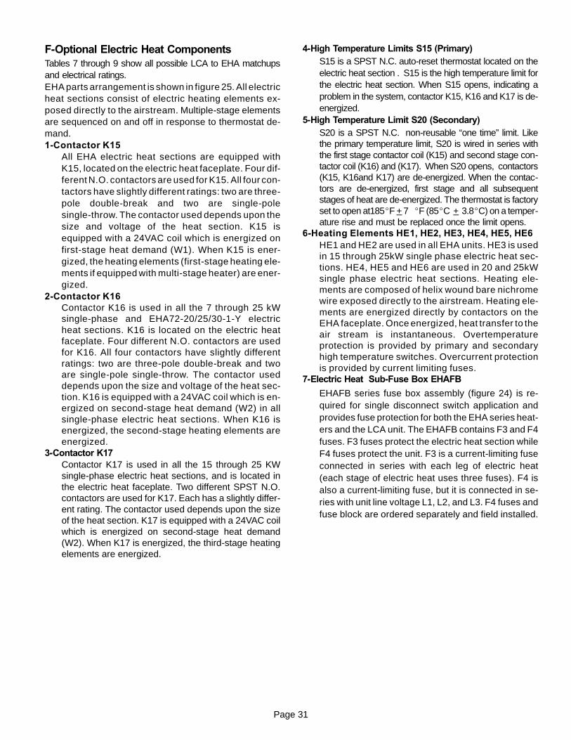
Page 31
F-Optional Electric Heat ComponentsTables 7 through 9 show all possible LCA to EHA matchupsand electrical ratings.EHA parts arrangement is shown in figure 25. All electricheat sections consist of electric heating elements ex-posed directly to the airstream. Multiple-stage elementsare sequenced on and off in response to thermostat de-mand.1-Contactor K15
All EHA electric heat sections are equipped withK15, located on the electric heat faceplate. Four dif-ferent N.O. contactors are used for K15. All four con-tactors have slightly different ratings: two are three-pole double-break and two are single-polesingle-throw. The contactor used depends upon thesize and voltage of the heat section. K15 isequipped with a 24VAC coil which is energized onfirst-stage heat demand (W1). When K15 is ener-gized, the heating elements (first-stage heating ele-ments if equipped with multi-stage heater) are ener-gized.
2-Contactor K16Contactor K16 is used in all the 7 through 25 kWsingle-phase and EHA72-20/25/30-1-Y electricheat sections. K16 is located on the electric heatfaceplate. Four different N.O. contactors are usedfor K16. All four contactors have slightly differentratings: two are three-pole double-break and twoare single-pole single-throw. The contactor useddepends upon the size and voltage of the heat sec-tion. K16 is equipped with a 24VAC coil which is en-ergized on second-stage heat demand (W2) in allsingle-phase electric heat sections. When K16 isenergized, the second-stage heating elements areenergized.
3-Contactor K17Contactor K17 is used in all the 15 through 25 KWsingle-phase electric heat sections, and is located inthe electric heat faceplate. Two different SPST N.O.contactors are used for K17. Each has a slightly differ-ent rating. The contactor used depends upon the sizeof the heat section. K17 is equipped with a 24VAC coilwhich is energized on second-stage heat demand(W2). When K17 is energized, the third-stage heatingelements are energized.
4-High Temperature Limits S15 (Primary)S15 is a SPST N.C. auto-reset thermostat located on theelectric heat section . S15 is the high temperature limit forthe electric heat section. When S15 opens, indicating aproblem in the system, contactor K15, K16 and K17 is de-energized.
5-High Temperature Limit S20 (Secondary)S20 is a SPST N.C. non-reusable “one time” limit. Likethe primary temperature limit, S20 is wired in series withthe first stage contactor coil (K15) and second stage con-tactor coil (K16) and (K17). When S20 opens, contactors(K15, K16and K17) are de-energized. When the contac-tors are de-energized, first stage and all subsequentstages of heat are de-energized. The thermostat is factoryset to open at185_F + 7 _F (85_C + 3.8_C) on a temper-ature rise and must be replaced once the limit opens.
6-Heating Elements HE1, HE2, HE3, HE4, HE5, HE6HE1 and HE2 are used in all EHA units. HE3 is usedin 15 through 25kW single phase electric heat sec-tions. HE4, HE5 and HE6 are used in 20 and 25kWsingle phase electric heat sections. Heating ele-ments are composed of helix wound bare nichromewire exposed directly to the airstream. Heating ele-ments are energized directly by contactors on theEHA faceplate. Once energized, heat transfer to theair stream is instantaneous. Overtemperatureprotection is provided by primary and secondaryhigh temperature switches. Overcurrent protectionis provided by current limiting fuses.
7-Electric Heat Sub-Fuse Box EHAFB
EHAFB series fuse box assembly (figure 24) is re-quired for single disconnect switch application andprovides fuse protection for both the EHA series heat-ers and the LCA unit. The EHAFB contains F3 and F4fuses. F3 fuses protect the electric heat section whileF4 fuses protect the unit. F3 is a current-limiting fuseconnected in series with each leg of electric heat(each stage of electric heat uses three fuses). F4 isalso a current-limiting fuse, but it is connected in se-ries with unit line voltage L1, L2, and L3. F4 fuses andfuse block are ordered separately and field installed.
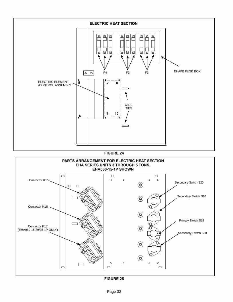
Page 32
5 7 8
69 10
J2 P2
FIGURE 24
ELECTRIC HEAT SECTION
WIRETIES
ELECTRIC ELEMENT/CONTROL ASSEMBLY
EHAFB FUSE BOXF4 F3 F3
FIGURE 25
PARTS ARRANGEMENT FOR ELECTRIC HEAT SECTIONEHA SERIES UNITS 3 THROUGH 5 TONS,
EHA060-15-1P SHOWN
Contactor K15
Contactor K16
Contactor K17(EHA060-15/20/25-1P ONLY)
Primary Switch S15
Secondary Switch S20
Secondary Switch S20
Secondary Switch S20
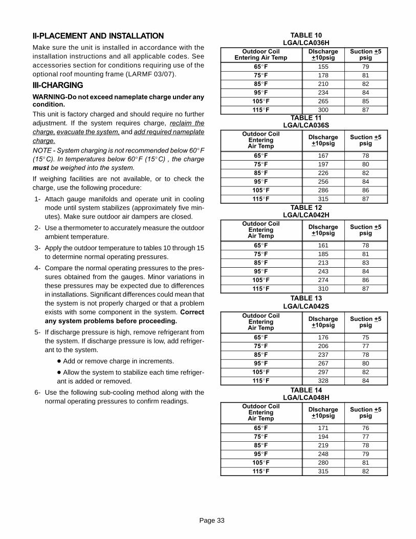
Page 33
II-PLACEMENT AND INSTALLATIONMake sure the unit is installed in accordance with theinstallation instructions and all applicable codes. Seeaccessories section for conditions requiring use of theoptional roof mounting frame (LARMF 03/07).
III-CHARGINGWARNING-Do not exceed nameplate charge under anycondition.
This unit is factory charged and should require no furtheradjustment. If the system requires charge, reclaim thecharge, evacuate the system, and add required nameplatecharge.
NOTE - System charging is not recommended below 60_F(15_C). In temperatures below 60_F (15_C) , the chargemust be weighed into the system.
If weighing facilities are not available, or to check thecharge, use the following procedure:
1- Attach gauge manifolds and operate unit in coolingmode until system stabilizes (approximately five min-utes). Make sure outdoor air dampers are closed.
2- Use a thermometer to accurately measure the outdoorambient temperature.
3- Apply the outdoor temperature to tables 10 through 15to determine normal operating pressures.
4- Compare the normal operating pressures to the pres-sures obtained from the gauges. Minor variations inthese pressures may be expected due to differencesin installations. Significant differences could mean thatthe system is not properly charged or that a problemexists with some component in the system. Correctany system problems before proceeding.
5- If discharge pressure is high, remove refrigerant fromthe system. If discharge pressure is low, add refriger-ant to the system.
D Add or remove charge in increments.
D Allow the system to stabilize each time refriger-ant is added or removed.
6- Use the following sub-cooling method along with thenormal operating pressures to confirm readings.
TABLE 10LGA/LCA036H
Outdoor CoilEntering Air Temp
DIscharge+10psig
Suction +5psig
65_F 155 7975_F 178 8185_F 210 8295_F 234 84
105_F 265 85115_F 300 87
TABLE 11LGA/LCA036S
Outdoor CoilEnteringAir Temp
DIscharge+10psig
Suction +5psig
65_F 167 7875_F 197 8085_F 226 8295_F 256 84
105_F 286 86115_F 315 87
TABLE 12LGA/LCA042H
Outdoor CoilEnteringAir Temp
DIscharge+10psig
Suction +5psig
65_F 161 7875_F 185 8185_F 213 8395_F 243 84
105_F 274 86115_F 310 87
TABLE 13LGA/LCA042S
Outdoor CoilEnteringAir Temp
DIscharge+10psig
Suction +5psig
65_F 176 7575_F 206 7785_F 237 7895_F 267 80
105_F 297 82115_F 328 84
TABLE 14LGA/LCA048H
Outdoor CoilEnteringAir Temp
DIscharge+10psig
Suction +5psig
65_F 171 7675_F 194 7785_F 219 7895_F 248 79
105_F 280 81115_F 315 82

Page 34
TABLE 15LGA/LCA048S
Outdoor CoilEnteringAir Temp
DIscharge+10psig
Suction +5psig
65_F 161 7375_F 191 7485_F 221 7695_F 251 78
105_F 281 80115_F 311 82
TABLE 16LGA/LCA060H
Outdoor CoilEnteringAir Temp
DIscharge+10psig
Suction +5psig
65_F 165 7575_F 192 7685_F 221 7895_F 253 80
105_F 287 82115_F 323 83
TABLE 17LGA/LCA060S
Outdoor CoilEnteringAir Temp
DIscharge+10psig
Suction +5psig
65_F 175 6975_F 206 7185_F 237 7395_F 267 75
105_F 298 76115_F 328 78
TABLE 18LGA/LCA072H
Outdoor CoilEnteringAir Temp
DIscharge+10psig
Suction +5psig
65_F 185 7675_F 210 7785_F 238 7895_F 269 80
105_F 304 81115_F 338 83
TABLE 19LGA/LCA072S
Outdoor CoilEnteringAir Temp
DIscharge+10psig
Suction +5psig
65_F 191 7175_F 224 7285_F 258 7495_F 292 75
105_F 326 77115_F 360 78
Charge Verification - Sub-Cooling MethodIf ambient temperature is above 60_F (15_C), read liquid linetemperature. Read liquid line pressure from gauge and con-vert to condensing temperature using standard R-22 temper-ature/pressure conversion chart (or conversion scale ongauge). The difference between the condensing temperatureand the liquid line temperature is subcooling (subcooling =condensing temperature minus liquid line temperature). Thesubcooling should approximate the value given in table 20.Add refrigerant to increase subcooling and remove refriger-ant to reduce subcooling.
NOTE - Outdoor air dampers should be closed whencharging.
TABLE 20SUBCOOLING
Unit Circuit 2
LGA/LCA036S, 036H, 042H, 10_F + 1(5.6_C + 1)LGA/LCA036S, 036H, 042H,048S, 048H, 072H
10_F + 1(5.6_C + 1)048S, 048H, 072H
LGA/LCA042S, 060H 11_F + 1(6.1_C + 1)LGA/LCA042S, 060H 11_F + 1(6.1_C + 1)
LGA/LCA060S 16_F + 1(9_C + 1)
LGA/LCA072S 19_F + 1(11_C + 1)
Page 35
IV-STARTUP - OPERATIONRefer to startup directions and refer closely to the unit wir-ing diagram when servicing. See unit nameplate for mini-mum circuit ampacity and maximum fuse size.
A-Preliminary and Seasonal Checks1- Make sure the unit is installed in accordance with the
installation instructions and applicable codes.
2- Inspect all electrical wiring, both field and factory installedfor loose connections. Tighten as required. Refer to unitdiagram located on inside of unit control box cover.
3- Check to ensure that refrigerant lines are in goodcondition and do not rub against the cabinet or otherrefrigerant lines.
4- Check voltage at the disconnect switch. Voltage mustbe within the range listed on the nameplate. If not,consult the power company and have the voltage cor-rected before starting the unit.
5- Recheck voltage and amp draw with unit running. Ifvoltage is not within range listed on unit nameplate,stop unit and consult power company. Refer to unitnameplate for maximum rated load amps.
6- Inspect and adjust blower belt (see section on BlowerCompartment - Blower Belt Adjustment).
B-Cooling Startup LGA/LCA
NOTE-Crankcase heaters must be energized 24 hours be-fore attempting to start compressor. Set thermostat so thatthere is no demand to prevent compressor from cycling.Apply power to unit.
1- Initiate cooling demand according to instructions pro-vided with thermostat.
2- Thermostat demand will energize compressor. Onunits with an economizer, when outdoor air is accept-able, a first-stage demand will energize the economiz-er; a second-stage demand will energize compressor1.
3- The unit is charged with HCFC-22 refrigerant. See unitrating plate for correct amount of charge.
4- Refer to Cooling Operation and Adjustment section forproper method to check refrigerant charge.
Three Phase Scroll Compressor Voltage Phasing
Three phase scroll compressors must be phased se-quentially to ensure correct compressor and blower rota-tion and operation. Compressor and blower are wired inphase at the factory. Power wires are color-coded as fol-lows: line 1-red, line 2-yellow, line 3-blue.
1- Observe suction and discharge pressures and blowerrotation on unit start-up.
2- Suction pressure must drop, discharge pressure mustrise, and blower rotation must match rotation marking.
If pressure differential is not observed or blower rotation isnot correct:
3- Disconnect all remote electrical power supplies.
4- Reverse any two field-installed wires connected to theline side of S48 disconnect or TB2 terminal strip. Donot reverse wires at blower contactor.
5- Make sure the connections are tight.Discharge and suction pressures should operate at theirnormal start-up ranges.
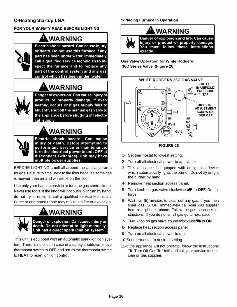
Page 36
C-Heating Startup LGA
FOR YOUR SAFETY READ BEFORE LIGHTING
Electric shock hazard. Can cause injuryor death. Do not use this furnace if anypart has been under water. Immediatelycall a qualified service technician to in-spect the furnace and to replace anypart of the control system and any gascontrol which has been under water.
WARNING!
Danger of explosion. Can cause injury orproduct or property damage. If over-heating occurs or if gas supply fails toshut off, shut off the manual gas valve tothe appliance before shutting off electri-cal supply.
WARNING!
Electric shock hazard. Can causeinjury or death. Before attempting toperform any service or maintenance,turn the electrical power to unit OFF atdisconnect switch(es). Unit may havemultiple power supplies.
WARNING!
BEFORE LIGHTING smell all around the appliance areafor gas. Be sure to smell next to the floor because some gasis heavier than air and will settle on the floor.
Use only your hand to push in or turn the gas control knob.Never use tools. If the knob will not push in or turn by hand,do not try to repair it, call a qualified service technician.Force or attempted repair may result in a fire or explosion.
Danger of explosion. Can cause injury ordeath. Do not attempt to light manually.Unit has a direct spark ignition system.
WARNING!
This unit is equipped with an automatic spark ignition sys-tem. There is no pilot. In case of a safety shutdown, movethermostat switch to OFF and return the thermostat switchto HEAT to reset ignition control.
1-Placing Furnace In Operation
Danger of explosion and fire. Can causeinjury or product or property damage.You must follow these instructionsexactly.
WARNING!
Gas Valve Operation for White Rodgers36C Series Valve (Figure 26)
WHITE RODGERS 36C GAS VALVE
FIGURE 26
D-1
GV-1C-1C2
GV-2
OUTLET(MANIFIOLD)PRESSURE
TAP
HIGH FIREADJUSTMENTSCREW UN-
DER CAP
1- Set thermostat to lowest setting.
2- Turn off all electrical power to appliance.
3- This appliance is equipped with an ignition devicewhich automatically lights the burner. Do not try to lightthe burner by hand.
4- Remove heat section access panel.
5- Turn knob on gas valve clockwise to OFF. Do notforce.
6- Wait five (5) minutes to clear out any gas. If you thensmell gas, STOP! Immediately call your gas supplierfrom a neighbor’s phone. Follow the gas supplier’s in-structions. If you do not smell gas go to next step.
7- Turn knob on gas valve counterclockwise to ON.
8- Replace heat section access panel.
9- Turn on all electrical power to unit.
10-Set thermostat to desired setting.
11-If the appliance will not operate, follow the instructions“To Turn Off Gas To Unit” and call your service techni-cian or gas supplier.

Page 37
Gas Valve Operation for Honeywell VR8205 andVR8305 Series Valve (Figure 27)
ON
OFF
HONEYWELL VR8205 / VR8305 SERIES GAS VALVE
GAS VALVE SHOWN IN OFF POSITION
FIGURE 27
VR8205 SHOWN
1- Set thermostat to lowest setting.
2- Turn off all electrical power to appliance.
3- This appliance is equipped with an ignition devicewhich automatically lights burner. Do not try to light theburner by hand.
4- Remove heat section access panel.
5- Turn knob on gas valve clockwise to OFF and re-lease.
6- Wait five minutes to clear out any gas. If you then smellgas, STOP! Immediately call your gas supplier from aneighbor’s phone. Follow the gas supplier’s instruc-tions. If you do not smell gas go to next step.
7- Turn knob on gas valve 90_ counterclockwise toon.
8- Replace heat section access panel.
9- Turn on electrical power to unit.
10-Set thermostat to desired setting.
11-The combustion air blower will start. The burners willlight within 40 seconds.
12-If unit does not light first time (gas line not fully purged)it will attempt up to two more ignitions before lockingout.
13-If lockout occurs, repeat steps 1 through 10.
14-If appliance still will not operate, follow the instructions“To Turn Off Gas to Unit” and call your service techni-cian or gas supplier.
2-To Turn Off Gas To Unit
1- Set thermostat to lowest setting.
2- Turn off all electrical power to unit if service is to be per-formed.
3- Remove heat section access panel.
4- Turn knob on gas valve clockwise to OFF. Depressknob and turn clockwise to OFF.
D-Safety or Emergency ShutdownTurn off power to the unit.
V- SYSTEMS SERVICE CHECKS
A-LGA Heating System Service ChecksAll LGA units are U.L. and U.L.C. design certified with-out modification.
Before checking piping, check with gas company or au-thorities having jurisdiction for local code requirements.Refer to the LGA Installation, Operation and Adjust-ments instruction for more information.
GAS PIPINGSUPPORT
GROUNDJOINTUNION
FIGURE 28
GAS PIPING COMPONENTS
FIELD PROVIDED1/8” (3.2 mm) PRESSURE
TAPVALVE
MANUAL MAINSHUT-OFF VALVE
(REFER TO LOCALCODES)
DRIP LEG
ROOFMOUNTING
FRAME
CAP HERE TOISOLATE VALVE
PRESSURETESTING
REFER TO INSTALLATION INSTRUCTIONS
1-Gas PipingGas supply piping must not allow more than 0.5”W.C.(124.3 Pa) drop in pressure between the gas meter andthe unit. Supply gas pipe must not be smaller than the unitgas connection. Refer to installation instructions for de-tails.
2-Testing Gas PipingNOTE-In case emergency shutdown is required, turn offthe main manual shut-off valve and disconnect the mainpower to the unit. These controls should be properly la-beled by the installer.
When pressure testing gas lines, the gas valve must be dis-connected and isolated. Gas valves can be damaged ifsubjected to more than 0.5 psig [14”W.C. (3481 Pa)]. Seefigure 28.
When checking piping connection for gas leaks, use thepreferred means. Common kitchen detergents cancause harmful corrosion on various metals used in gaspiping. The use of specialty Gas Leak Detector isstrongly recommended. It is available through Lennoxunder part number 31B2001.
Do not use matches, candles, flame or any other sourceof ignition to check for gas leaks.
Page 38
3-Testing Gas Supply PressureWhen testing gas supply pressure, connect test gauge to theinlet pressure tap (field provided - figure 28). Test supply gaspressure with unit firing at maximum rate (both stages en-ergized). Make sure the reading falls within the range ofthe following values. Low pressure may result in erratic op-eration or “underfire.” High pressure can result in perma-nent damage to the gas valve or “overfire.” For naturalgas units, operating pressure at the unit gas connectionmust be between 5.5”W.C. and 10.5”W.C. (1367 Pa and2610 Pa) For L.P. gas units, operating pressure at theunit gas connection must be between 10.8”W.C. and13.5”W.C. (2685.3 Pa and 3356.7 Pa).On multiple unit installations, each unit should be checkedseparately while operating at maximum rate, beginning withthe one closest to the supply gas main and progressing tothe one furthest from the main. Multiple units shouldalso be tested with and without the other units operat-ing. Supply pressure must fall within the range listed inthe previous paragraph.
4-Check and Adjust Manifold PressureAfter line pressure has been checked and adjusted,check manifold pressure. Move test gauge to the man-ifold outlet pressure tap located on unit gas valve GV1.See figure 20 or 21 for location of pressure tap on the gasvalve.The manifold pressure is factory set and should not re-quire adjustment. If manifold pressure is incorrect and no othersource of improper manifold pressure can be found, the valvemust be replaced. Refer to figure 20 or 21 for location of gasvalve (manifold pressure) adjustment screw. See tables belowfor normal operating manifold pressure. White Rodgers twostage valves are adjustable for high fire only. Honeywell twostage vavles are adjustable for both high fire and low fire.All gas valves are factory regulated. The gas valve shouldcompletely and immediately cycle off in the event of gas orpower failure. The manual shut-off knob can be used to imme-diately shut off gas supply.
TABLE 21SINGLE STAGE GAS VALVE FACTORY SETTING
Natural (inlet-5.5” to 10.5”) L.P (inlet-11.0” to 13.0”)
3.5” + 0.3” 10.5” + 0.3”
TABLE 22TWO STAGE GAS VALVE FACTORY SETTING
Natural (inlet-5.5” to 10.0”) L.P. (11.0” to 13.0”)
High Fire Low Fire High Fire Low Fire
3.7” + 0.3” 1.9” + 0.2” 10.5” + 0.3” 5.32” + 0.2”
CAUTIONFor safety, connect a shut-off valve between themanometer and the gas tap to permit shut off ofgas pressure to the manometer.
Manifold Adjustment Procedure
1- Connect test gauge to the outlet pressure tap on thegas valve. Start the unit (call for second stage heat)and allow five minutes for the unit to reach steadystate.
2- While waiting for the unit to stabilize, notice theflame. The flame should be stable without flashbackand should not lift from the burner heads. Naturalgas should burn basically blue with some clearstreaks. L.P. gas should burn mostly blue with someclear yellow streaks.
3- After allowing the unit to stabilize for five minutes, re-cord the manifold pressure and compare to the valuesgiven for gas supply pressure (above).
CAUTIONDisconnect heating demand as soon as an accuratereading has been obtained.
5-Proper Gas Flow
To check for proper gas flow to burners, determine Btuh in-put from unit rating plate or the gas heating capacity table onpage 3. Divide this input rating by the Btuh per cubic foot ofavailable gas. Result is the number of cubic feet per hour re-quired. Determine the flow of gas through gas meter for twominutes and multiply by 30 to get hourly flow of gas to theburners.
NOTE - To obtain accurate reading, shut off all other gasappliances connected to meter.
6-High Altitude DerateNatural gas units may be installed at altitudes up to 2000feet (610m) above sea level without any modification. At al-titudes above 2000 feet (610 m), units must be derated tomatch gas manifold pressures shown in the following table.NOTE-This is the only permissible derate for these units.
TABLE 23Altitude - ft. (m) Gas Manifold Pressure - in. w.g. (kPa)
2001 - 3000 (610 - 915) 3.4 (0.85)
3001 - 4000 (915 - 1220) 3.2 (0.807)
4001 - 5000 (1220 - 1525) 2.9 (0.72)
5001 - 6000 (1525 - 1830) 2.7 (0.67)
6001 - 7000 (1830 - 2135) 2.5 (0.62)
7001 - 8000 (2135 - 2440) 2.3 (0.57)
Derate Procedure:
1- Check manifold pressure at the gas valve pressure tapwith unit operating at high fire (second stage).
2- To reduce maximum input, turn regulator adjusting screw(figure 20) counterclockwise.
3- Re-check manifold pressure.
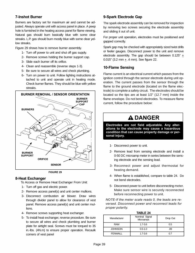
Page 39
7-Inshot BurnerBurners are factory set for maximum air and cannot be ad-justed. Always operate unit with access panel in place. A peephole is furnished in the heating access panel for flame viewing.Natural gas should burn basically blue with some clearstreaks. L.P. gas should burn mostly blue with some clear yel-low streaks.
Figure 29 shows how to remove burner assembly.
1- Turn off power to unit and shut off gas supply.
2- Remove screws holding the burner support cap.
3- Slide each burner off its orifice.4- Clean and reassemble (reverse steps 1-3).
5- Be sure to secure all wires and check plumbing.
6- Turn on power to unit. Follow lighting instructions at-tached to unit and operate unit in heating mode.Check burner flames. They should be blue with yellowstreaks.
FIGURE 29
BURNER REMOVAL / SENSOR ORIENTATION
BURNERS
ORIFICE
BURNERSUPPORT
BURNERSUPPORT
CAP
SENSOR
8-Heat ExchangerTo Access or Remove Heat Exchanger From Unit:
1- Turn off gas and electric power.
2- Remove access panel(s) and unit center mullions.
3- Disconnect combustion air blower. Draw wiresthrough divider panel to allow for clearance of vestpanel. Remove access panel(s) and unit center mul-lions.
4- Remove screws supporting heat exchanger.
5- To install heat exchanger, reverse procedure. Be sureto secure all wires and check plumbing and burnerplate for airtight seal. Screws must be torqued to 35in.-lbs. (4N.m) to ensure proper operation. Recaulkcorners of vest panel
9-Spark Electrode Gap
The spark electrode assembly can be removed for inspectionby removing two screws securing the electrode assemblyand sliding it out of unit.
For proper unit operation, electrodes must be positioned andgapped correctly.
Spark gap may be checked with appropriately sized twist drillsor feeler gauges. Disconnect power to the unit and removeelectrode assembly. The gap should be between 0.125” +0.015” (3.2 mm + .4 mm). See figure 22.
10-Flame Sensing
Flame current is an electrical current which passes from theignition control through the sensor electrode during unit op-eration. The current passes from the sensor through theflame to the ground electrode (located on the flame elec-trode) to complete a safety circuit. The electrodes should belocated so the tips are at least 1/2” (12.7 mm) inside theflame envelope. Do not bend electrodes. To measure flamecurrent, follow the procedure below:
DANGERElectrodes are not field adjustable. Any alter-ations to the electrode may cause a hazardouscondition that can cause property damage or per-sonal injury.
1- Disconnect power to unit.
2- Remove lead from sensing electrode and install a0-50 DC microamp meter in series between the sens-ing electrode and the sensing lead.
3- Reconnect power and adjust thermostat forheating demand.
4- When flame is established, compare to table 24. Donot bend electrodes.
5- Disconnect power to unit before disconnecting meter.Make sure sensor wire is securely reconnectedbefore reconnecting power to unit.
NOTE-If the meter scale reads 0, the leads are re-versed. Disconnect power and reconnect leads forproper polarity.
TABLE 24
ManufacturerNominal Signal
Microamps Drop Out
RAM 1.7-3.6 0.5
JOHNSON 0.5-1.0 .09
FENWALL 1.7-3.6 0.7
Page 40
11-Combustion Air BlowerThe combustion air blower is factory set and is not field adjust-able. However, operation should be monitored to ensure prop-er operation. The combustion air blower is used to draw freshair into the combustion chamber while simultaneously ex-pelling exhaust gases. The blower operates throughoutthe heating cycle.On a heating demand, the ignition control is energized by themain control module A55. The ignition control then allows apre-purge of 30 to 40 seconds for the combustion air blower tovent exhaust gases from the burners. When the com-bustion air blower is purging the exhaust gases, thecombustion air prove switch is closing proving that the com-bustion air blower is operating before allowing the ignition con-trol to energize. When the combustion air prove switch isclosed and the delay is over, the ignition control activates thegas valve, the spark and flame sense electrode. The spark willend when flame is sensed. Units with the White Rodgers gasvalve will activate on first stage (low fire) with the spark andthe flame sensing electrode. Sparking stops immedi-ately after flame is sensed.
B-Cooling System Service ChecksLGA / LCA units are factory charged and require no further ad-justment; however, charge should be checked periodically us-ing the subcooling method. The subcooling method comparesactual liquid temperature with the condensing temperature ofthe refrigerant.
1-Gauge Manifold AttachmentService gauge ports are identified in figure 7. Attach highpressure line to discharge line schrader port and the low pres-sure line to the suction line schrader port.
NOTE-When unit is properly charged discharge and suc-tion line pressures should approximate those in tables 10through 14.
VI-MAINTENANCE
CAUTIONElectrical shock hazard. Turn off power to unitbefore performing any maintenance, cleaning orservice operation on the unit.
A-FiltersLGA / LCA units are equipped with two 16” x 25” x 2”(406mm x 635mm x 51mm) pleated throw-away type fil-ters. Filters may be accessed through the economizer /filter access door at the end of the unit. Filters should bechecked monthly (or more frequently in severe use) andreplaced regularly. Take note of the “AIR FLOW DI-RECTION” marking on the filter frame when re-instal-ling.
NOTE-Filters must be U.L.C. certified or equivalent foruse in Canada.
B-LubricationAll motors and blower wheels used in LGA / LCA unitsare prelubricated; no further lubrication is required.
C-Supply Air Blower WheelAnnually inspect supply air blower wheel for accumulateddirt or dust. Turn off power before attempting to removeaccess panel or to clean blower wheel.
CAUTIONBe careful when servicing unit to avoid accidentalcontact with sharp metallic edges which maycause personal injury.
D-Evaporator CoilInspect and clean coil at beginning of each season. Cleanusing mild detergent or commercial coil cleanser. Checkcondensate drain pan and line, if necessary. Flush coil andcondensate drain with water taking care not to get insula-tion, filters and return air ducts wet. Check connectinglines and coil for evidence of oil and refrigerant leaks.
E-Condenser CoilClean condenser coil annually with detergent or com-mercial coil cleaner and inspect monthly during the cool-ing season. Check connecting lines and coil for evidenceof oil and refrigerant leaks.
NOTE-If owner complains of insufficient cooling, theunit should be gauged and refrigerant charge checked.Refer to Gauge Manifold Attachment and Chargingsections in this manual.
F-Electrical1- Check all wiring for loose connections.
2- Check for correct voltage at unit (unit operating).
3- Check amp-draw on both condenser fan motor andblower motor.Fan Motor Rating Plate ____ Actual ________Indoor Blower Motor Rating Plate____ Actual____

Page 41
VII-ACCESSORIESThe accessories section describes the application of most ofthe optional accessories which can be factory or field installedto either the LGA / LCA units.
A-LARMF03/07-14,24 Mounting FramesWhen installing either the LGA / LCA units on a combustiblesurface for downflow discharge applications, the LennoxLARMF03/07 14-inch or 24-inch height roof mounting frame isused. The roof mounting frames are recommended in all otherapplications but not required. If the LGA / LCA units are notmounted on a flat (roof) surface, they MUST be supported un-der all edges and under the middle of the unit to prevent sag-ging. The units MUST be mounted level within 1/16” per linearfoot or 5mm per meter in any direction.
FIGURE 30
ASSEMBLED ROOF MOUNTING FRAME
LARMF 03/07
SUPPLY AIR CROSS SUPPORT
CENTER SUPPORT
RETURN AIR CROSSSUPPORT
The assembled LARMF03/07 mounting frame is shown in fig-ure 30. Refer to the roof mounting frame installation instruc-tions for details of proper assembly and mounting. The roofmounting frame MUST be squared to the roof and level beforemounting. Plenum system MUST be installed before the unit isset on the mounting frame. Typical roof curbing and flashing isshown in figure 31. Refer to the roof mounting frame installa-tion instructions for proper plenum construction and attach-ment.
FIGURE 31
ROOFMOUNTING FRAME
(Extends around entireperimeter of unit)
FIBERGLASSINSULATION(Furnished)
COUNTER FLASHING(Field Supplied)
UNIT BASEBOTTOM
RIGID INSULATION(Field Supplied)
ROOFINGMATERIAL
CANT STRIP(Field Supplied)
NAILER STRIP(Furnished)
UNIT BASE RAIL
TYPICAL FLASHINGDETAIL
B-TransitionsOptional supply/return transitions LASRT 03/06 orLASRT 07 are available for use with LGA / LCA seriesunits utilizing optional LARMF 03/07 roof mountingframe. Transition must be installed in the LARMFmounting frame before mounting the unit to the frame.Refer to the manufacturer’s instructions included with thetransition for detailed installation procedures.
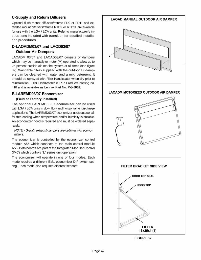
Page 42
C-Supply and Return DiffusersOptional flush mount diffusers/returns FD9 or FD11 and ex-tended mount diffusers/returns RTD9 or RTD11 are availablefor use with the LGA / LCA units. Refer to manufacturer’s in-structions included with transition for detailed installa-tion procedures.
D-LAOADM03/07 and LAOD03/07Outdoor Air Dampers
LAOADM 03/07 and LAOAD03/07 consists of damperswhich may be manually or motor (M) operated to allow up to25 percent outside air into the system at all times (see figure32). Washable filters supplied with the outdoor air damp-ers can be cleaned with water and a mild detergent. Itshould be sprayed with Filter Handicoater when dry prior toreinstallation. Filter Handicoater is R.P. Products coating no.418 and is available as Lennox Part No. P-8-5069.
E-LAREMD03/07 Economizer(Field or Factory Installed)
The optional LAREMD03/07 economizer can be usedwith LGA / LCA units in downflow and horizontal air dischargeapplications. The LAREMD03/07 economizer uses outdoor airfor free cooling when temperature and/or humidity is suitable.An economizer hood is required and must be ordered sepa-rately.
NOTE - Gravity exhaust dampers are optional with econo-mizers.
The economizer is controlled by the economizer controlmodule A56 which connects to the main control moduleA55. Both boards are part of the Integrated Modular Control(IMC) which controls “L” series unit operation.
The economizer will operate in one of four modes. Eachmode requires a different EM1 economizer DIP switch set-ting. Each mode also requires different sensors.
LAOADM MOTORIZED OUTDOOR AIR DAMPER
LAOAD MANUAL OUTDOOR AIR DAMPER
FIGURE 32
FILTER BRACKET SIDE VIEW
HOOD TOP
FILTER16x25x1 (1)
HOOD TOP SEAL
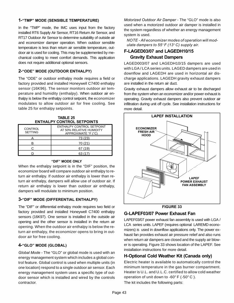
Page 43
1-“TMP” MODE (SENSIBLE TEMPERATURE)
In the “TMP” mode, the IMC uses input from the factoryinstalled RT6 Supply Air Sensor, RT16 Return Air Sensor, andRT17 Outdoor Air Sensor to determine suitability of outside airand economizer damper operation. When outdoor sensibletemperature is less than return air sensible temperature, out-door air is used for cooling. This may be supplemented by me-chanical cooling to meet comfort demands. This applicationdoes not require additional optional sensors.
2-“ODE” MODE (OUTDOOR ENTHALPY)
The “ODE” or outdoor enthalpy mode requires a field orfactory provided and installed Honeywell C7400 enthalpysensor (16K96). The sensor monitors outdoor air tem-perature and humidity (enthalpy). When outdoor air en-thalpy is below the enthalpy control setpoint, the economizermodulates to allow outdoor air for free cooling. Seetable 25 for enthalpy setpoints.
ENTHALPY CONTROL SETPOINTS
CONTROLSETTING
ENTHALPY CONTROL SETPOINTAT 50% RELATIVE HUMIDITY
APPROXIMATE °F (°C)
A
B
C
D
73 (23)
70 (21)
67 (19)
63 (17)
TABLE 25
“DIF” MODE ONLY
When the enthalpy setpoint is in the “DIF” position, theeconomizer board will compare outdoor air enthalpy to re-turn air enthalpy. If outdoor air enthalpy is lower than re-turn air enthalpy, dampers will allow use of outdoor air. Ifreturn air enthalpy is lower than outdoor air enthalpy,dampers will modulate to minimum position.
3-“DIF” MODE (DIFFERENTIAL ENTHALPY)
The “DIF” or differential enthalpy mode requires two field orfactory provided and installed Honeywell C7400 enthalpysensors (16K97). One sensor is installed in the outside airopening and the other sensor is installed in the return airopening. When the outdoor air enthalpy is below the re-turn air enthalpy, the economizer opens to bring in out-door air for free cooling.
4-“GLO” MODE (GLOBAL)
Global Mode - The “GLO” or global mode is used with anenergy management system which includes a global con-trol feature. Global control is used when multiple units (inone location) respond to a single outdoor air sensor. Eachenergy management system uses a specific type of out-door sensor which is installed and wired by the controlscontractor.
Motorized Outdoor Air Damper - The “GLO” mode is alsoused when a motorized outdoor air damper is installed inthe system regardless of whether an energy managementsystem is used.
NOTE - All economizer modes of operation will mod-ulate dampers to 55_F (13_C) supply air.
F-LAGED03/07 and LAGEDH10/15Gravity Exhaust Dampers
LAGED003/07 and LAGEDH10/15 dampers are usedwith LGA / LCA series units. LAGED dampers are used indownflow and LAGEDH are used in horizontal air dis-charge applications. LAGEDH gravity exhaust dampersare installed in the return air duct.
Gravity exhaust dampers allow exhaust air to be dischargedfrom the system when an economizer and/or power exhaust isoperating. Gravity exhaust dampers also prevent outdoor airinfiltration during unit off cycle. See installation instructions formore detail.
FIGURE 33
LAPEF INSTALLATION
LAPEFPOWER EXHAUSTFAN ASSEMBLY
ECONOMIZERFRESH AIR
HOOD
G-LAPEF03/07 Power Exhaust FanLAPEF03/07 power exhaust fan assembly is used with LGA /LCA series units. LAPEF (requires optional LAREMD econo-mizers) is used in downflow applications only. The power ex-haust fan provides exhaust air pressure relief and also runswhen return air dampers are closed and the supply air blow-er is operating. Figure 33 shows location of the LAPEF. Seeinstallation instructions for more detail.
H-Optional Cold Weather Kit (Canada only)Electric heater is available to automatically control theminimum temperature in the gas burner compartment.Heater is U.L. and U.L.C. certified to allow cold weatheroperation of unit down to -60° F (-50° C ).
The kit includes the following parts:
Page 44
1- Transformer (T20) is a 600V to 120/240V stepdown trans-former mounted in the blower compartment.
2- T20 has two in line fuses (F20), one on each leg of the trans-former. Both are rated at 15 amps.
3- The strip heater (HR6) is located as close as possible to thegas valve. It is wired in series with T20. The strip heater israted at 500 Watts
4- A thermostat mounting box is installed on the vesti-bule of the heating compartment. Included in the boxare the following thermostat switches:
a - Thermostat switch (S59) is an auto-reset SPST .switch which acts as a low limit and opens on a tem-perature drop. The switch is wired to open 24v pow-er to the burner control. When the temperature dropsbelow -35° C (-30° F) the switch opens and the gas heatsection is de-energized. The switch automatically re-sets when the heating compartment temperaturereaches -12° C (10° F).
b - Thermostat switch (S60) is an auto-reset SPSTswitch and is the controller of HR6. When the tem-perature rises above -7° C (20° F) the switch opensand the electric heater is de-energized. The switchautomatically resets when the heating compartmenttemperature reaches -23.3° C (-10° F).
c -Thermostat switch (S61) is an auto-reset SPSTswitch which acts as a high limit and closes on atemperature drop. S61 remains closed during lowambient conditions and opens when tempera-tures rise. When temperature drops below -6.7° C(20° F) the switch closes. The switch automatical-ly opens when heating compartment temperaturereaches 24° C (76° F).
I-Control SystemsThree different types of control systems may be used withthe LGA / LCA series units. All thermostat wiring is con-nected to terminal block TB1 located in the blowercompartment of the unit. Each thermostat has additionalcontrol options available. See thermostat installation in-structions for more detail.
1- Electro-mechanical thermostat (13F06)
The electro-mechanical thermostat is a two stage heat /two stage cool thermostat with dual temperature levers.A non-switching or manual system switch subbasemay be used.
2- Electronic thermostat (see price book)
Any two stage heat / two stage cool electronic ther-mostat may be used.
3- Honeywell T7300 thermostat (81G59)
The Honeywell T7300 thermostat is a programmable, in-ternal or optional remote temperature sensing thermo-stat. The T7300 provides occupied and unoccupiedchangeover control.
J-Smoke Detectors A17 and A64Photoelectric smoke detectors are a factory installed op-tion. The smoke detectors can be installed in the supply airsection (A64), return air section (A17), or in both the supplyand return air section. Wiring for the smoke detectors areshown on the temperature control section (C2) wiring dia-gram in back of this manual.
K-Blower Proving Switch S52The blower proving switch monitors blower operation andlocks out the unit in case of blower failure. The switch isN.O. and closes at .14” W.C. (34.9 Pa) The switch ismounted on the upper left hand corner of the blower deck inthe blower compartment. Wiring for the blower proving switchis shown on the temperature control section (C2) wiring dia-gram in back of this manual.
L-Dirty Filter Switch S27The dirty filter switch senses static pressure increase indi-cating a dirty filter condition. The switch is N.O. and closesat 1” W.C. (248.6 Pa) The switch is mounted on the top filterchannel corner. Wiring for the dirty filter switch is shown onthe temperature control section (C2) wiring diagram in back ofthis manual.
M-Indoor Air Quality (CO2) Sensor A63The indoor air quality sensor monitors CO2 levels and re-ports the levels to the main control module A55. The boardadjusts the economizer dampers according to the CO2levels. The sensor is mounted next to the indoor thermo-stat or in the return air duct. Refer to the indoor air qualitysensor installation instructions for proper adjustment.Wiring for the indoor air quality switch is shown on the tem-perature control section (C2) wiring diagram in back of thismanual.
N-LP / Propane KitA natural to LP / propane gas changeover kit is required forgas conversion on LGA036/072 series units. The kit includesa gas valve and burner orifices.
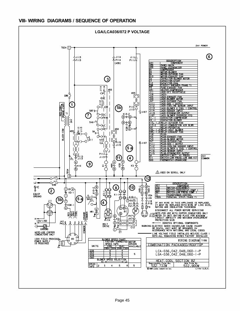
Page 45
VIII- WIRING DIAGRAMS / SEQUENCE OF OPERATION
LGA/LCA036/072 P VOLTAGE
1
2
3
4
6
8
9
10
11
12
7
4
5 a
5 a
5b
5b

Page 46
LGA/LCA036/072 Y VOLTAGE
1
2
3
4
6
8
9
10
11
12
7
4
5 a
5 a
5b
5b
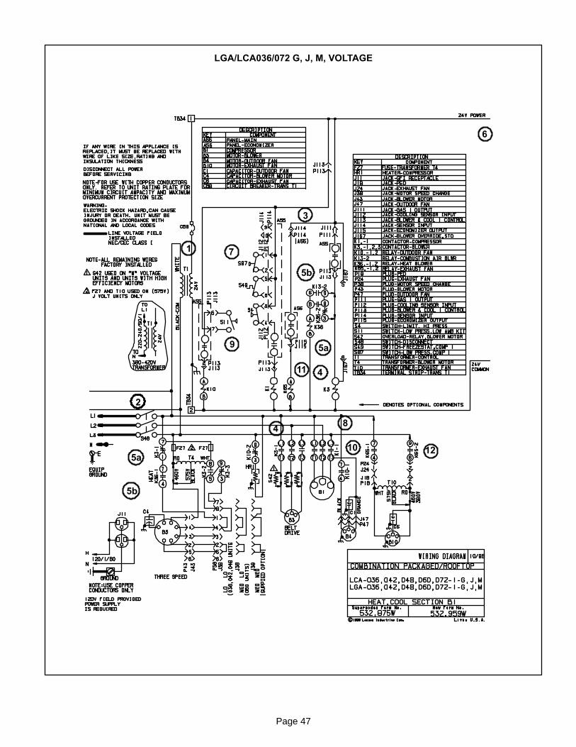
Page 47
LGA/LCA036/072 G, J, M, VOLTAGE
1
2
3
4
5a
6
7
8
9
10
5a
5b
5b
4
11
12
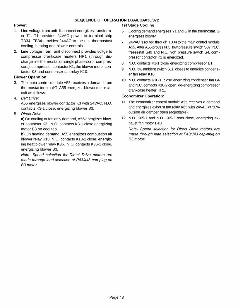
Page 48
SEQUENCE OF OPERATION LGA/LCA036/072Power:1. Line voltage from unit disconnect energizes transform-
er T1. T1 provides 24VAC power to terminal stripTB34. TB34 provides 24VAC to the unit thermostastcooling, heating and blower controls.
2. Line voltage from unit disconnect provides voltge tocompressor crankcase heaters HR1 (through dis-charge line thermostat on single phase scroll compres-sors), compressor contactor K1, the blower motor con-tactor K3 and condenser fan relay K10.
Blower Operation:3. The main control module A55 receives a demand from
thermostat terminal G. A55 energizes blower motor cir-cuit as follows:
4. Belt Drive:A55 energizes blower contactor K3 with 24VAC. N.O.contacts K3-1 close, energizing blower B3.
5. Direct Drive:a) On cooling or fan only demand, A55 energizes blow-er contactor K3. N.O. contacts K3-1 close energizingmotor B3 on cool tap.b) On heating demand, A55 energizes combustion airblower relay K13. N.O. contacts K13-2 close, energiz-ing heat blower relay K36. N.O. contacts K36-1 close,energizing blower B3.Note- Speed selection for Direct Drive motors aremade through lead selection at P43/J43 cap-plug onB3 motor.
1st Stage Cooling
6. Cooling demand energizes Y1 and G in the thermostat. Genergizes blower.
7. 24VAC is routed through TB34 to the main control moduleA55. After A55 proves N.C. low pressure switch S87, N.C.freezestat S49 and N.C. high pressure switch S4, com-pressor contactor K1 is energized.
8. N.O. contacts K1-1 close energizing compressor B1.
9. N.O. low ambient switch S11 closes to energize condens-er fan relay K10.
10. N.O. contacts K10-1 close energizing condenser fan B4and N.C. contacts K10-2 open, de-energizing compressorcrankcase heater HR1.
Economizer Operation:
11. The economizer control module A56 receives a demandand energizes exhaust fan relay K65 with 24VAC at 50%outside air damper open (adjustable).
12. N.O. K65-1 and N.O. K65-2 both close, energizing ex-haust fan motor B10.
Note- Speed selection for Direct Drive motors aremade through lead selection at P43/J43 cap-plug onB3 motor.
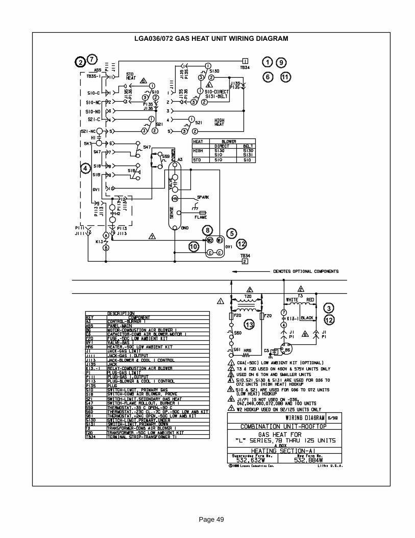
Page 49
LGA036/072 GAS HEAT UNIT WIRING DIAGRAM
12
3
4
5
6
7
8
9
10
11
12
12
13
Page 50
SEQUENCE OF OPERATION LGA036/072 GAS HEAT
First or Single Stage Heat:
1. Heating demand initiates at W1 in the thermostat.
2. 24VAC is routed through TB34 to the main controlmodule A55. After A55 proves N.C. primary limit S21,the combustion air blower relay K13 is energized.
3. N.O. K13-1 contacts close allowing line voltage to en-ergize combustion air blower B6.
4. After the combustion air blower B6 has reached fullspeed, the combustion air proving switch S18 contactsclose. The A55 routes 24VAC through N.C. burnerflame rollout switch S47 and the closed contacts ofcombustion air proving switch S18 to energize the igni-tion module A3.
5. After a 30 second delay A3 energizes the ignitor andW1 terminal (low fire) of two stage gas valve GV1.
Second Stage Heat:
6. With first stage heat operating, an additional heatingdemand initiates W2 in the thermostat.
7. A second stage heating demand is received by A55control module.
8. A55 energizes W2 terminal (high fire) of gas valveGV1.
End of Second Stage Heat:
9. Heating demand is satisfied. Terminal W2 (high fire) isde-energized.
10. Terminal W2 of GV1 is de-energized by A55 controlmodule.
End of First Stage Heat:
11. Heating demand is satisfied. Terminal W1 (low fire) isde-energized.
12. Ignition A3 is de-energized by control module A55 inturn de-energizing terminal W1 of GV1. Combustionair blower relay K13 is also de-energized.
Optional Low Ambient Kit:(C.G.A. -50° C Low Ambient Kit)
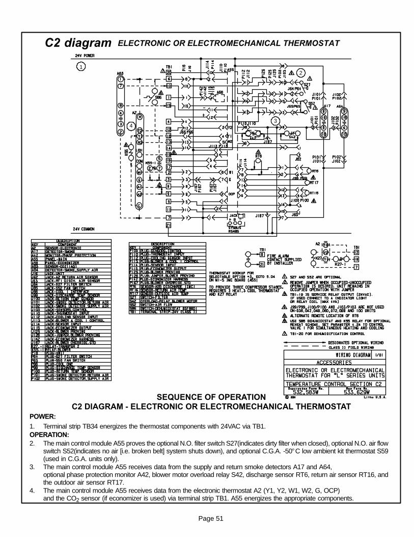
Page 51
C2 diagram ELECTRONIC OR ELECTROMECHANICAL THERMOSTAT
12
4
SEQUENCE OF OPERATIONC2 DIAGRAM - ELECTRONIC OR ELECTROMECHANICAL THERMOSTAT
POWER:
1. Terminal strip TB34 energizes the thermostat components with 24VAC via TB1.OPERATION:2. The main control module A55 proves the optional N.O. filter switch S27(indicates dirty filter when closed), optional N.O. air flow
switch S52(indicates no air [i.e. broken belt] system shuts down), and optional C.G.A. -50° C low ambient kit thermostat S59(used in C.G.A. units only).
3. The main control module A55 receives data from the supply and return smoke detectors A17 and A64,optional phase protection monitor A42, blower motor overload relay S42, discharge sensor RT6, return air sensor RT16, andthe outdoor air sensor RT17.
4. The main control module A55 receives data from the electronic thermostat A2 (Y1, Y2, W1, W2, G, OCP)and the CO2 sensor (if economizer is used) via terminal strip TB1. A55 energizes the appropriate components.
3

Page 52
“L” SERIES ECONOMIZER
SEQUENCE OF OPERATIONL” SERIES ECONOMIZER
POWER:
1. Terminal strip TB34 energizes the economizer components with 24VAC.
OPERATION:
2. The main control module A55 along with outdoor enthalpy sensor A7 and indoor enthalpy sensor A62(if differential enthalpy is used) communicates to the economizer control module A56 when to power thedamper motor B7.
3. The economizer control module A56 supplies B7 with 0 - 10 VDC to control the positioning of economizer.
4. The damper actuator provides 2 to 10 VDC position feedback.
1
2
3 4

Page 53
EHA-7 / 30kW Y VOLTAGE
1
2
3
3
3
4
5
6 9
10
7
8 11
12
13
Page 54
Sequence of Operation -EHA 7 / 30kW - Y and G, J, M
NOTE: This sequence of operation is for all ElectricHeat kW ratings and Y through J voltages. Each stepof operation is numbered and can be followed in se-quence on the diagrams. Operation for G, J, and Mvoltages will be the same.
HEATING ELEMENTS:
1 - Terminal Strip TB3 is energized when the unit discon-nect closes. TB3 supplies line voltage to Heat Contac-tors K15 and K16, which supplies voltage to HE1through HE6. Each element is protected by fuse F3.
FIRST STAGE HEAT:
2 - Heating demand initiates at W1 in thermostat.
3 - 24VAC is routed through TB34 to the main controlmodule A55. After A55 proves N.C. primary limit S15and secondary limit S20, the electric heat contactorK15 is energized.
4 - N.O. contacts K15-1 closes allowing the first bank ofelements to be energized.
SECOND STAGE HEAT:
5 - With the first stage heat operating, an additional heat-ing demand initiates at W2 in the thermostat.
6 - 24VAC is routed through the main control module A55,which in turn energizes the electric heat contactor K16.
7 - N.O. contacts K16-1 close allowing the second set ofelements to be energized.
END OF SECOND STAGE HEAT:
8 - Heating demand is satisfied. Terminal W2 in the ther-mostat is de-energized.
9 - Electric heat contactor K16 is de-energized.
10- The second set of electric heat elements are de-ener-gized.
END OF FIRST STAGE HEAT:
11- Heating demand is satisfied. Terminal W1 in the ther-mostat is de-energized.
12- Electric heat contactor K15 is de-energized.
13- The first set of electric heat elements are de-energized.

Page 55
SERVICE NOTES