Embed Size (px)
Citation preview
1
Service Manual – AP Series REV NO : 1
AP Series
Service Manual
LAST Rev. NO : 1 LAST Rev. Date : 2010. 05. 03
2
Service Manual – AP Series REV NO : 1
Table of Contents 1. Proper Operation / Introduction...................................................................................................................... 4
1.1. Preface .................................................................................................................................................. 4
1.2. Precaution.............................................................................................................................................. 4
1.3. Specification .......................................................................................................................................... 4
2. Classification ................................................................................................................................................... 5
2.1. Overall View.......................................................................................................................................... 5
2.2. Display Pad (Key Pad) .......................................................................................................................... 5
2.2.2. AP-EURO(AP-EX Type)............................................................................................................. 6
2.3. Serial Communiction ............................................................................................................................. 8
3. Getting Started ................................................................................................................................................ 8
3.1. Installation ............................................................................................................................................. 8
3.2. User setup .................................................................................오류! 책갈피가 정의되어 있지 않습니다.
4. Calibration Mode ............................................................................................................................................. 9
4.1. To enter Calibration mode .................................................................................................................... 9
4.2. C4 Setting ............................................................................................................................................ 10
4.2.1. C4-1 Setting (AD) ..................................................................................................................... 10
4.2.2. C4-2 Setting (Sale functions) ................................................................................................... 10
4.2.3. C4-3 Setting (Sale functions) ................................................................................................... 10
4.2.4. C4-4 Setting (Sale functions) ................................................................................................... 11
4.2.5. C4-5 Setting (Sale functions) ................................................................................................... 11
4.3. SPAN Calibration Setting (C-3).......................................................................................................... 12
4.4. Gravity Constant Value Setting (C-9) ................................................................................................ 12
4.5. Calibration factor Setting (C-10)........................................................................................................ 12
* CAL-10 TABLE....................................................................................................................................... 13
4.6. Displaying Raw A/D Value (C-5) ........................................................................................................ 14
4.7. Allocate Function Key Codes to Changeable keys (C-6) .................................................................. 15
* CHANGEABLE KEYS & SOFT KEY CODES........................................................................................... 15
* FIXED KEYS & THEIR SOFT KEY CODES............................................................................................. 16
4.8. Percent Calibration (C-7) ................................................................................................................... 17
4.9. Battery Calibration (C-8).................................................................................................................... 17
5. Servicing & Parts Replacement.................................................................................................................... 17
5.1. Trouble shooting ................................................................................................................................. 17
5.2. Error Message..................................................................................................................................... 18
5.3. The way to exchange parts ................................................................................................................ 19
5.3.1. To change Load cell .................................................................................................................. 19
6. Update ........................................................................................................................................................... 19
6.1. ROM Download Method....................................................................................................................... 19

3
Service Manual – AP Series REV NO : 1 7. Exploded Views & Parts List........................................................................................................................ 25
8. Revision......................................................................................................................................................... 27
4
Service Manual – AP Series REV NO : 1
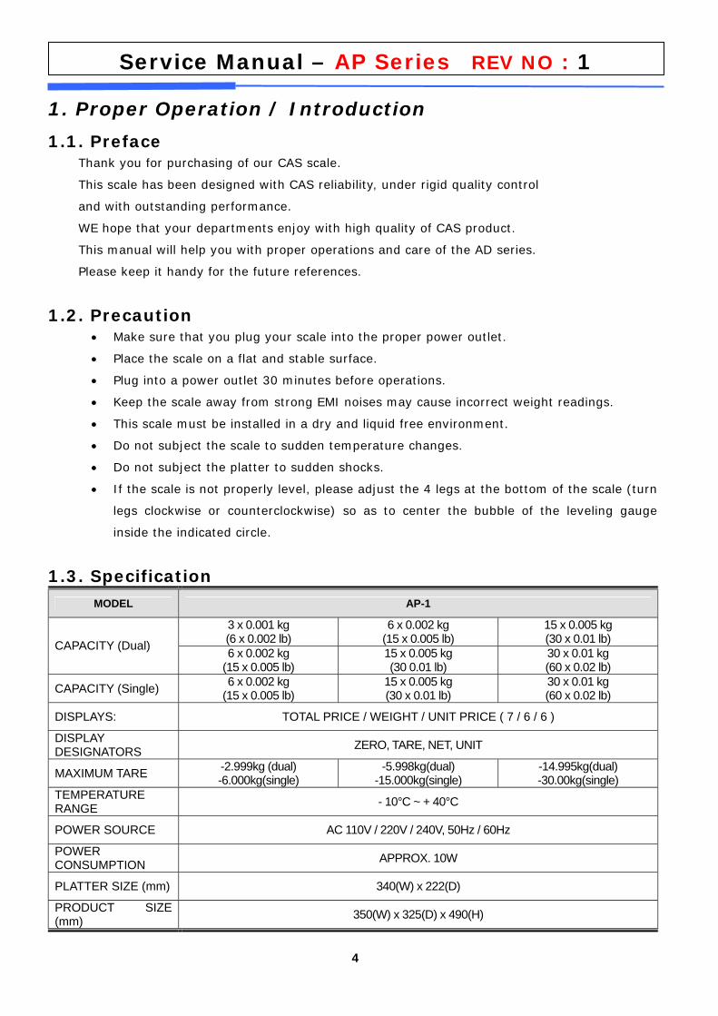
1. Proper Operation / Introduction
1.1. Preface Thank you for purchasing of our CAS scale.
This scale has been designed with CAS reliability, under rigid quality control
and with outstanding performance.
WE hope that your departments enjoy with high quality of CAS product.
This manual will help you with proper operations and care of the AD series.
Please keep it handy for the future references.
1.2. Precaution • Make sure that you plug your scale into the proper power outlet.
• Place the scale on a flat and stable surface.
• Plug into a power outlet 30 minutes before operations.
• Keep the scale away from strong EMI noises may cause incorrect weight readings.
• This scale must be installed in a dry and liquid free environment.
• Do not subject the scale to sudden temperature changes.
• Do not subject the platter to sudden shocks.
• If the scale is not properly level, please adjust the 4 legs at the bottom of the scale (turn
legs clockwise or counterclockwise) so as to center the bubble of the leveling gauge
inside the indicated circle.
1.3. Specification MODEL AP-1
3 x 0.001 kg (6 x 0.002 lb)
6 x 0.002 kg (15 x 0.005 lb)
15 x 0.005 kg (30 x 0.01 lb) CAPACITY (Dual) 6 x 0.002 kg
(15 x 0.005 lb) 15 x 0.005 kg (30 0.01 lb)
30 x 0.01 kg (60 x 0.02 lb)
CAPACITY (Single) 6 x 0.002 kg (15 x 0.005 lb)
15 x 0.005 kg (30 x 0.01 lb)
30 x 0.01 kg (60 x 0.02 lb)
DISPLAYS: TOTAL PRICE / WEIGHT / UNIT PRICE ( 7 / 6 / 6 )
DISPLAY DESIGNATORS ZERO, TARE, NET, UNIT
MAXIMUM TARE -2.999kg (dual) -6.000kg(single)
-5.998kg(dual) -15.000kg(single)
-14.995kg(dual) -30.00kg(single)
TEMPERATURE RANGE - 10°C ~ + 40°C
POWER SOURCE AC 110V / 220V / 240V, 50Hz / 60Hz
POWER CONSUMPTION APPROX. 10W
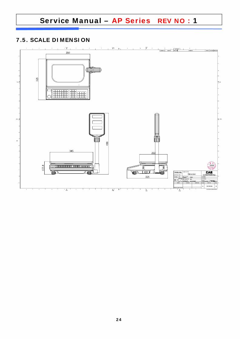
PLATTER SIZE (mm) 340(W) x 222(D)
PRODUCT SIZE (mm) 350(W) x 325(D) x 490(H)
5
Service Manual – AP Series REV NO : 1
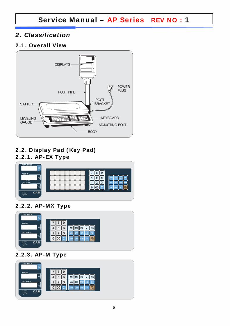
2. Classification
2.1. Overall View
2.2. Display Pad (Key Pad) 2.2.1. AP-EX Type
2.2.2. AP-MX Type
2.2.3. AP-M Type
6
Service Manual – AP Series REV NO : 1
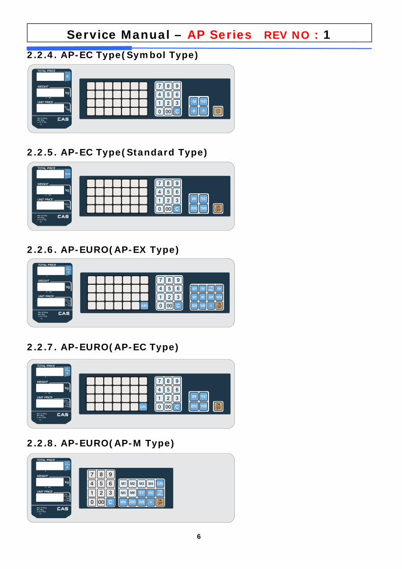
2.2.4. AP-EC Type(Symbol Type)
2.2.5. AP-EC Type(Standard Type)
2.2.6. AP-EURO(AP-EX Type)
2.2.7. AP-EURO(AP-EC Type)
2.2.8. AP-EURO(AP-M Type)
7
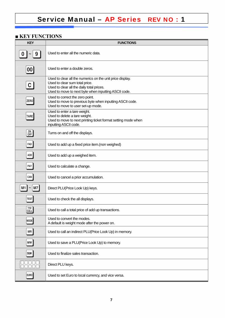
Service Manual – AP Series REV NO : 1 ■ KEY FUNCTIONS
KEY FUNCTIONS
Used to enter all the numeric data.
Used to enter a double zeros.
Used to clear all the numerics on the unit price display. Used to clear sum total price. Used to clear all the daily total prices. Used to move to next byte when inputting ASCII code.
Used to correct the zero point. Used to move to previous byte when inputting ASCII code. Used to move to user set-up mode.
Used to enter a tare weight. Used to delete a tare weight. Used to move to next printing ticket format setting mode when inputting ASCII code.
Turns on and off the displays.
Used to add up a fixed price item.(non weighed)
Used to add up a weighed item.
Used to calculate a change.
Used to cancel a prior accumulation.
Direct PLU(Price Look Up) keys.
Used to check the all displays.
Used to call a total price of add up transactions.
Used to convert the modes. A default is weight mode after the power on.
Used to call an indirect PLU(Price Look Up) in memory.
Used to save a PLU(Price Look Up) to memory.
Used to finalize sales transaction.
Direct PLU keys.
Used to set Euro to local currency, and vice versa.
8
Service Manual – AP Series REV NO : 1
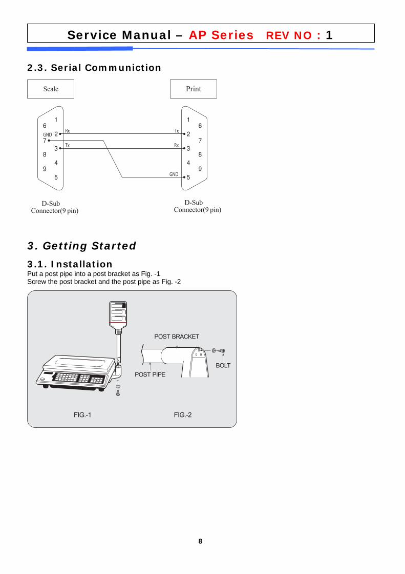
2.3. Serial Communiction
3. Getting Started
3.1. Installation Put a post pipe into a post bracket as Fig. -1 Screw the post bracket and the post pipe as Fig. -2
9
Service Manual – AP Series REV NO : 1
4. Calibration Mode
4.1. To enter Calibration mode Hold down “ Calibration Switch” and “ [POWER] key” to enter Calibration mode and then the scale
displays “ CAL 1” after “ onE” .
User can move to other menu by using [ZERO] key (Next) or [CAN] key (Previous).
User can also enter the sub-menus in each mode by using [TARE] key.
If you want to escape from the selected mode, Press the [C] key.
To confirm the modified setting, press the [TARE] key.
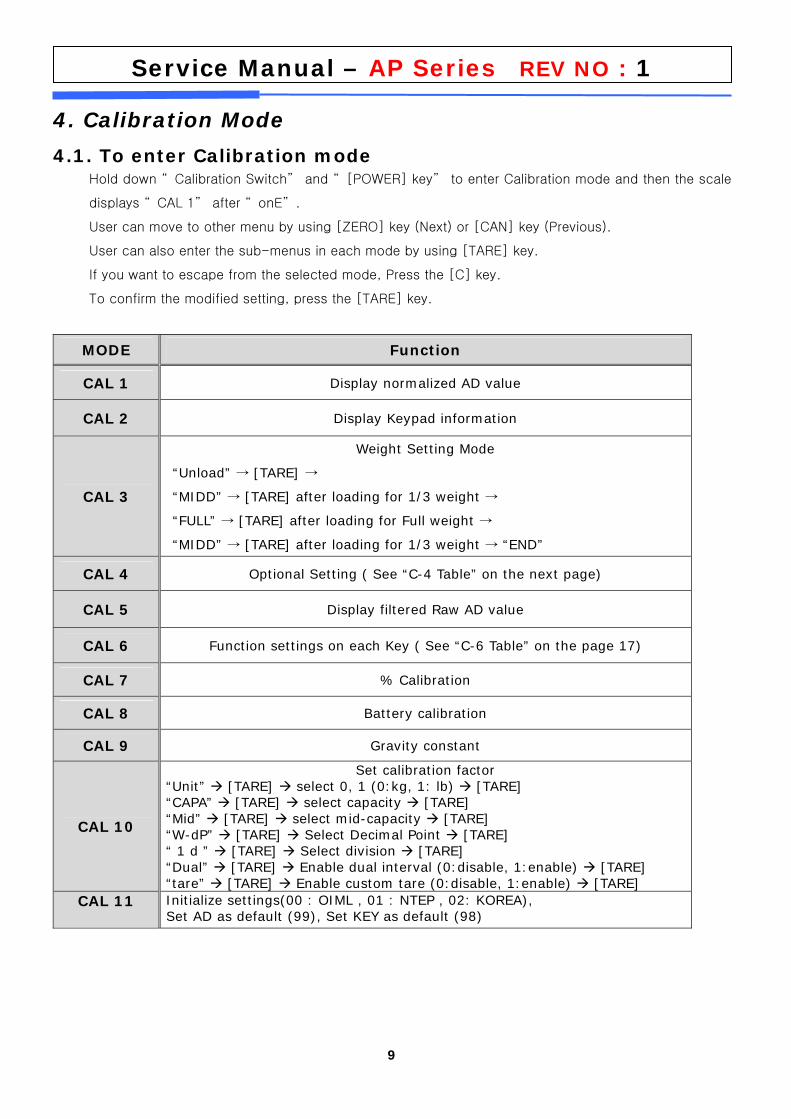
MODE Function
CAL 1 Display normalized AD value
CAL 2 Display Keypad information
CAL 3
Weight Setting Mode
“Unload” [TARE] → →
“MIDD” [TARE] after loading for 1/3 weight → →
“FULL” [TARE] after loading for Full weight → →
“MIDD” [TARE] after loading for 1/3 weight → “END”→
CAL 4 Optional Setting ( See “C-4 Table” on the next page)
CAL 5 Display filtered Raw AD value
CAL 6 Function settings on each Key ( See “C-6 Table” on the page 17)
CAL 7 % Calibration
CAL 8 Battery calibration
CAL 9 Gravity constant
CAL 10
Set calibration factor “Unit” [TARE] select 0, 1 (0:kg, 1: lb) [TARE] “CAPA” [TARE] select capacity [TARE] “Mid” [TARE] select mid-capacity [TARE] “W-dP” [TARE] Select Decimal Point [TARE] “ 1 d ” [TARE] Select division [TARE] “Dual” [TARE] Enable dual interval (0:disable, 1:enable) [TARE] “tare” [TARE] Enable custom tare (0:disable, 1:enable) [TARE]
CAL 11 Initialize settings(00 : OIML , 01 : NTEP , 02: KOREA), Set AD as default (99), Set KEY as default (98)
10
Service Manual – AP Series REV NO : 1
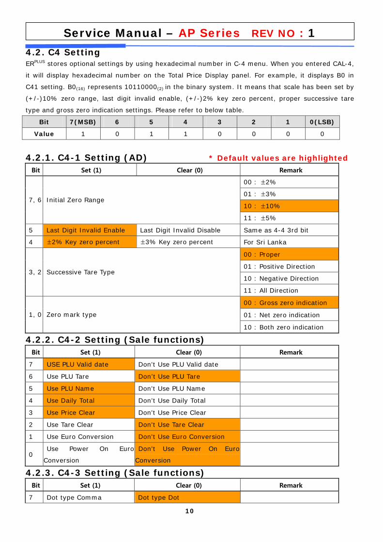
4.2. C4 Setting ERPLUS stores optional settings by using hexadecimal number in C-4 menu. When you entered CAL-4,
it will display hexadecimal number on the Total Price Display panel. For example, it displays B0 in
C41 setting. B0(16) represents 10110000(2) in the binary system. It means that scale has been set by
(+/-)10% zero range, last digit invalid enable, (+/-)2% key zero percent, proper successive tare
type and gross zero indication settings. Please refer to below table.
Bit 7(MSB) 6 5 4 3 2 1 0(LSB)
Value 1 0 1 1 0 0 0 0
4.2.1. C4-1 Setting (AD) * Default values are highlighted
Bit Set (1) Clear (0) Remark
00 : ±2%
01 : ±3%
10 : ±10% 7, 6 Initial Zero Range
11 : ±5%
5 Last Digit Invalid Enable Last Digit Invalid Disable Same as 4-4 3rd bit
4 ±2% Key zero percent ±3% Key zero percent For Sri Lanka
00 : Proper
01 : Positive Direction
10 : Negative Direction 3, 2 Successive Tare Type
11 : All Direction
00 : Gross zero indication
01 : Net zero indication 1, 0 Zero mark type
10 : Both zero indication
4.2.2. C4-2 Setting (Sale functions) Bit Set (1) Clear (0) Remark
7 USE PLU Valid date Don't Use PLU Valid date
6 Use PLU Tare Don’t Use PLU Tare
5 Use PLU Name Don't Use PLU Name
4 Use Daily Total Don't Use Daily Total
3 Use Price Clear Don't Use Price Clear
2 Use Tare Clear Don't Use Tare Clear
1 Use Euro Conversion Don't Use Euro Conversion
0 Use Power On Euro
Conversion
Don't Use Power On Euro
Conversion
4.2.3. C4-3 Setting (Sale functions) Bit Set (1) Clear (0) Remark
7 Dot type Comma Dot type Dot
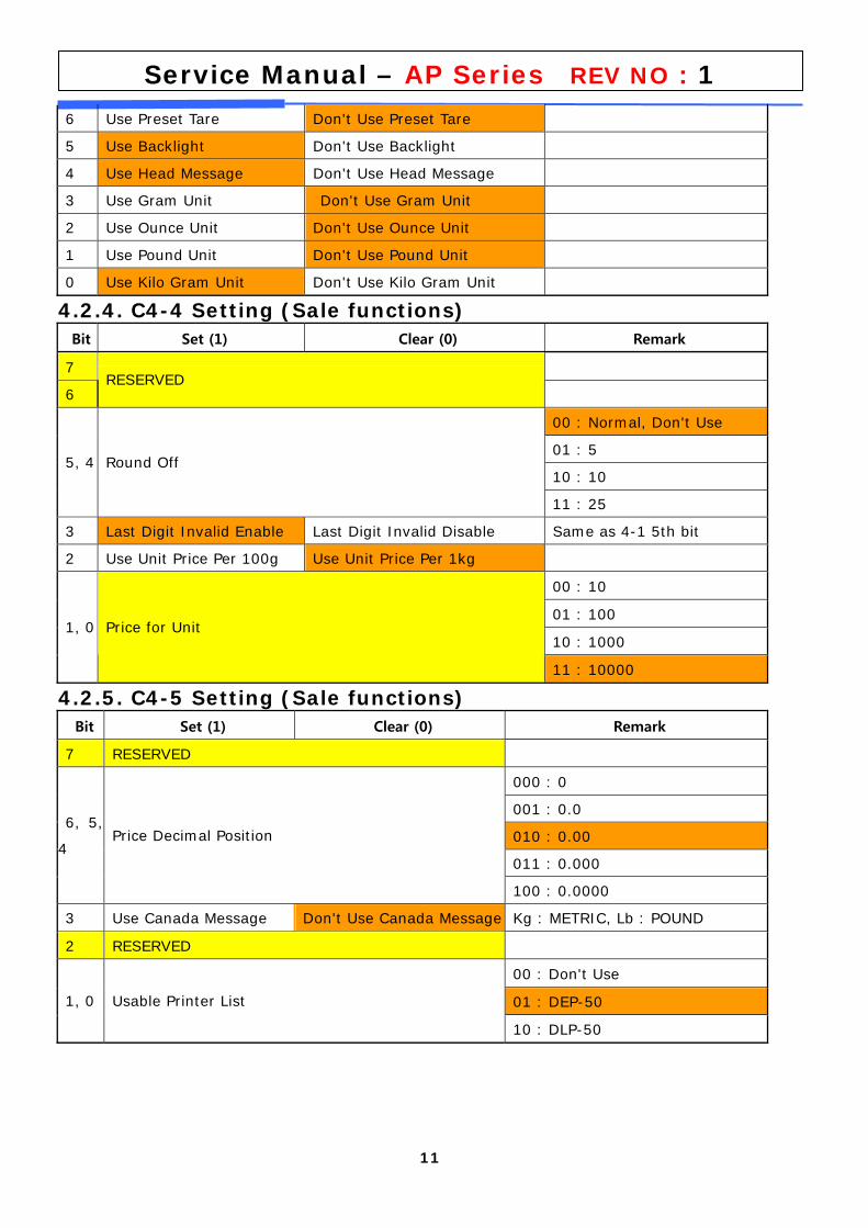
11
Service Manual – AP Series REV NO : 1
6 Use Preset Tare Don't Use Preset Tare
5 Use Backlight Don't Use Backlight
4 Use Head Message Don't Use Head Message
3 Use Gram Unit Don't Use Gram Unit
2 Use Ounce Unit Don't Use Ounce Unit
1 Use Pound Unit Don't Use Pound Unit
0 Use Kilo Gram Unit Don't Use Kilo Gram Unit
4.2.4. C4-4 Setting (Sale functions) Bit Set (1) Clear (0) Remark
7
6 RESERVED
00 : Normal, Don't Use
01 : 5
10 : 10 5, 4 Round Off
11 : 25
3 Last Digit Invalid Enable Last Digit Invalid Disable Same as 4-1 5th bit
2 Use Unit Price Per 100g Use Unit Price Per 1kg
00 : 10
01 : 100
10 : 1000 1, 0 Price for Unit
11 : 10000
4.2.5. C4-5 Setting (Sale functions) Bit Set (1) Clear (0) Remark
7 RESERVED
000 : 0
001 : 0.0
010 : 0.00
011 : 0.000
6, 5,
4 Price Decimal Position
100 : 0.0000
3 Use Canada Message Don't Use Canada Message Kg : METRIC, Lb : POUND
2 RESERVED
00 : Don't Use
01 : DEP-50 1, 0 Usable Printer List
10 : DLP-50
12
Service Manual – AP Series REV NO : 1
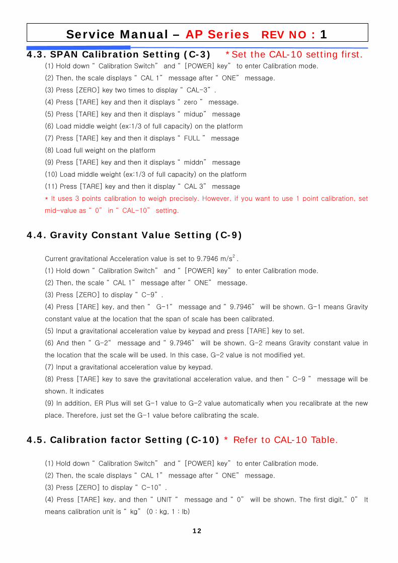
4.3. SPAN Calibration Setting (C-3) *Set the CAL-10 setting first. (1) Hold down “ Calibration Switch” and “ [POWER] key” to enter Calibration mode.
(2) Then, the scale displays “ CAL 1” message after “ ONE” message.
(3) Press [ZERO] key two times to display “ CAL-3” .
(4) Press [TARE] key and then it displays “ zero ” message.
(5) Press [TARE] key and then it displays “ midup” message
(6) Load middle weight (ex:1/3 of full capacity) on the platform
(7) Press [TARE] key and then it displays “ FULL ” message
(8) Load full weight on the platform
(9) Press [TARE] key and then it displays “ middn” message
(10) Load middle weight (ex:1/3 of full capacity) on the platform
(11) Press [TARE] key and then it display “ CAL 3” message
* It uses 3 points calibration to weigh precisely. However, if you want to use 1 point calibration, set
mid-value as “ 0” in “ CAL-10” setting.
4.4. Gravity Constant Value Setting (C-9)
Current gravitational Acceleration value is set to 9.7946 m/s2 .
(1) Hold down “ Calibration Switch” and “ [POWER] key” to enter Calibration mode.
(2) Then, the scale “ CAL 1” message after “ ONE” message.
(3) Press [ZERO] to display “ C-9” .
(4) Press [TARE] key, and then “ G-1“ message and “ 9.7946” will be shown. G-1 means Gravity
constant value at the location that the span of scale has been calibrated.
(5) Input a gravitational acceleration value by keypad and press [TARE] key to set.
(6) And then “ G-2“ message and “ 9.7946” will be shown. G-2 means Gravity constant value in
the location that the scale will be used. In this case, G-2 value is not modified yet.
(7) Input a gravitational acceleration value by keypad.
(8) Press [TARE] key to save the gravitational acceleration value, and then “ C-9 ” message will be
shown. It indicates
(9) In addition, ER Plus will set G-1 value to G-2 value automatically when you recalibrate at the new
place. Therefore, just set the G-1 value before calibrating the scale.
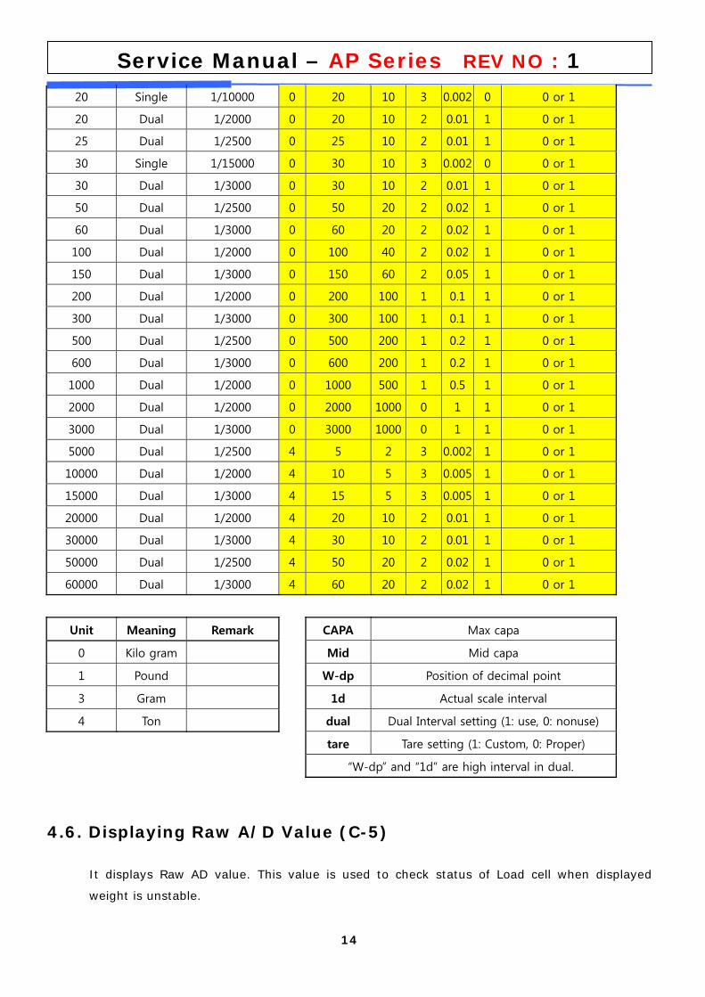
4.5. Calibration factor Setting (C-10) * Refer to CAL-10 Table.
(1) Hold down “ Calibration Switch” and “ [POWER] key” to enter Calibration mode.
(2) Then, the scale displays “ CAL 1” message after “ ONE” message.
(3) Press [ZERO] to display “ C-10” .
(4) Press [TARE] key, and then “ UNIT “ message and “ 0” will be shown. The first digit,” 0” It
means calibration unit is “ kg” (0 : kg, 1 : lb)
13
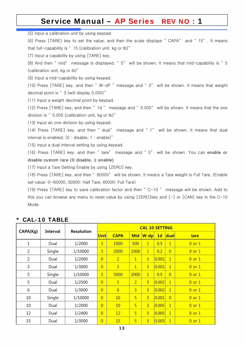
Service Manual – AP Series REV NO : 1 (5) Input a calibration unit by using keypad.
(6) Press [TARE] key to set the value, and then the scale displays “ CAPA“ and “ 15” . It means
that full-capability is “ 15 (calibration unit, kg or lb)”
(7) Input a capability by using [TARE] key.
(8) And then “ mid“ message is displayed. “ 5” will be shown. It means that mid-capability is “ 5
(calibration unit, kg or lb)”
(9) Input a mid-capability by using keypad.
(10) Press [TARE] key, and then “ W-dP “ message and “ 3” will be shown. It means that weight
decimal point is “ 3 (will display 0.000)”
(11) Input a weight decimal point by keypad.
(12) Press [TARE] key, and then “ 1d “ message and “ 0.005” will be shown. It means that the one
division is “ 0.005 (calibration unit, kg or lb)”
(13) Input an one division by using keypad.
(14) Press [TARE] key, and then “ dual” message and “ 1” will be shown. It means that dual
interval is enabled. (0 : disable, 1 : enable)”
(15) Input a dual interval setting by using keypad.
(16) Press [TARE] key, and then “ tare” message and “ 0” will be shown. You can enable or
disable custom tare (0:disable, 1:enable)
(17) Input a Tare Setting Enable by using [ZERO] key.
(18) Press [TARE] key, and then “ 60000” will be shown. It means a Tare weight is Full Tare. (Enable
set value: 0~60000, 30000: Half Tare, 60000: Full Tare)
(19) Press [TARE] key to save calibration factor and then “ C-10 ” message will be shown. Add to
this you can browse any menu to reset value by using [ZERO]key and [-] or [CAN] key in the C-10
Mode.
* CAL-10 TABLE
CAL 10 SETTING CAPA(Kg) Interval Resolution
Unit CAPA Mid W-dp 1d dual tare
1 Dual 1/2000 3 1000 500 1 0.5 1 0 or 1
2 Single 1/10000 3 2000 1000 1 0.2 0 0 or 1
2 Dual 1/2000 0 2 1 3 0.001 1 0 or 1
3 Dual 1/3000 0 3 1 3 0.001 1 0 or 1
5 Single 1/10000 3 5000 2000 1 0.5 0 0 or 1
5 Dual 1/2500 0 5 2 3 0.002 1 0 or 1
6 Dual 1/3000 0 6 3 3 0.002 1 0 or 1
10 Single 1/10000 0 10 5 3 0.001 0 0 or 1
10 Dual 1/2000 0 10 5 3 0.005 1 0 or 1
12 Dual 1/2400 0 12 5 3 0.005 1 0 or 1
15 Dual 1/3000 0 15 5 3 0.005 1 0 or 1
14
Service Manual – AP Series REV NO : 1
20 Single 1/10000 0 20 10 3 0.002 0 0 or 1
20 Dual 1/2000 0 20 10 2 0.01 1 0 or 1
25 Dual 1/2500 0 25 10 2 0.01 1 0 or 1
30 Single 1/15000 0 30 10 3 0.002 0 0 or 1
30 Dual 1/3000 0 30 10 2 0.01 1 0 or 1
50 Dual 1/2500 0 50 20 2 0.02 1 0 or 1
60 Dual 1/3000 0 60 20 2 0.02 1 0 or 1
100 Dual 1/2000 0 100 40 2 0.02 1 0 or 1
150 Dual 1/3000 0 150 60 2 0.05 1 0 or 1
200 Dual 1/2000 0 200 100 1 0.1 1 0 or 1
300 Dual 1/3000 0 300 100 1 0.1 1 0 or 1
500 Dual 1/2500 0 500 200 1 0.2 1 0 or 1
600 Dual 1/3000 0 600 200 1 0.2 1 0 or 1
1000 Dual 1/2000 0 1000 500 1 0.5 1 0 or 1
2000 Dual 1/2000 0 2000 1000 0 1 1 0 or 1
3000 Dual 1/3000 0 3000 1000 0 1 1 0 or 1
5000 Dual 1/2500 4 5 2 3 0.002 1 0 or 1
10000 Dual 1/2000 4 10 5 3 0.005 1 0 or 1
15000 Dual 1/3000 4 15 5 3 0.005 1 0 or 1
20000 Dual 1/2000 4 20 10 2 0.01 1 0 or 1
30000 Dual 1/3000 4 30 10 2 0.01 1 0 or 1
50000 Dual 1/2500 4 50 20 2 0.02 1 0 or 1
60000 Dual 1/3000 4 60 20 2 0.02 1 0 or 1
Unit Meaning Remark CAPA Max capa
0 Kilo gram Mid Mid capa
1 Pound W-dp Position of decimal point
3 Gram 1d Actual scale interval
4 Ton dual Dual Interval setting (1: use, 0: nonuse)
tare Tare setting (1: Custom, 0: Proper)
“W-dp” and “1d” are high interval in dual.
4.6. Displaying Raw A/D Value (C-5)
It displays Raw AD value. This value is used to check status of Load cell when displayed
weight is unstable.
15
Service Manual – AP Series REV NO : 1
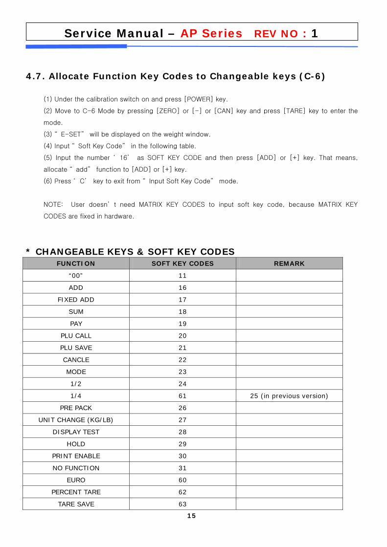
4.7. Allocate Function Key Codes to Changeable keys (C-6)
(1) Under the calibration switch on and press [POWER] key.
(2) Move to C-6 Mode by pressing [ZERO] or [-] or [CAN] key and press [TARE] key to enter the
mode.
(3) “ E-SET” will be displayed on the weight window.
(4) Input “ Soft Key Code” in the following table.
(5) Input the number ‘ 16’ as SOFT KEY CODE and then press [ADD] or [+] key. That means,
allocate “ add” function to [ADD] or [+] key.
(6) Press ‘ C’ key to exit from “ Input Soft Key Code” mode.
NOTE: User doesn’ t need MATRIX KEY CODES to input soft key code, because MATRIX KEY
CODES are fixed in hardware.
* CHANGEABLE KEYS & SOFT KEY CODES FUNCTION SOFT KEY CODES REMARK
“00” 11
ADD 16
FIXED ADD 17
SUM 18
PAY 19
PLU CALL 20
PLU SAVE 21
CANCLE 22
MODE 23
1/2 24
1/4 61 25 (in previous version)
PRE PACK 26
UNIT CHANGE (KG/LB) 27
DISPLAY TEST 28
HOLD 29
PRINT ENABLE 30
NO FUNCTION 31
EURO 60
PERCENT TARE 62
TARE SAVE 63
16
Service Manual – AP Series REV NO : 1
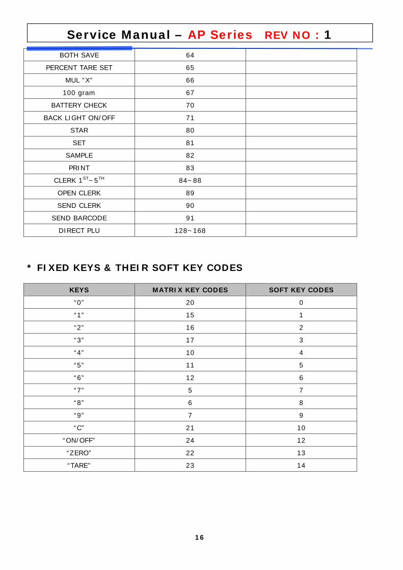
BOTH SAVE 64
PERCENT TARE SET 65
MUL ”X” 66
100 gram 67
BATTERY CHECK 70
BACK LIGHT ON/OFF 71
STAR 80
SET 81
SAMPLE 82
PRINT 83
CLERK 1ST~5TH 84~88
OPEN CLERK 89
SEND CLERK 90
SEND BARCODE 91
DIRECT PLU 128~168
* FIXED KEYS & THEIR SOFT KEY CODES
KEYS MATRIX KEY CODES SOFT KEY CODES
“0” 20 0
“1” 15 1
“2” 16 2
“3” 17 3
“4” 10 4
“5” 11 5
“6” 12 6
“7” 5 7
“8” 6 8
“9” 7 9
“C” 21 10
“ON/OFF” 24 12
“ZERO” 22 13
“TARE” 23 14
17
Service Manual – AP Series REV NO : 1
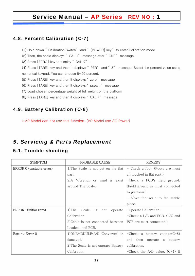
4.8. Percent Calibration (C-7)
(1) Hold down “ Calibration Switch” and “ [POWER] key” to enter Calibration mode.
(2) Then, the scale displays “ CAL 1” message after “ ONE” message.
(3) Press [ZERO] key to display “ CAL-7” .
(4) Press [TARE] key and then it displays “ PER” and “ 5” message. Select the percent value using
numerical keypad. You can choose 5~90 percent.
(5) Press [TARE] key and then it displays “ zero” message
(6) Press [TARE] key and then it displays “ pspan ” message
(7) Load chosen percentage weight of full weight on the platform
(8) Press [TARE] key and then it displays “ CAL 7” message
4.9. Battery Calibration (C-8)
* AP Model can not use this function. (AP Model use AC Power)
5. Servicing & Parts Replacement
5.1. Trouble shooting
SYMPTOM PROBABLE CAUSE REMEDY
ERROR 0 (unstable error)
1)The Scale is not put on the flat
part.
2)A Vibration or wind is exist
around The Scale.
- Check a foot. (Foots are must
all touched in flat part.)
-Check a PCB’s field ground.
(Field ground is must connected
to platform.)
- Move the scale to the stable
place.
ERROR 1(initial zero) 1)The Scale is not operate
Calibration
2)Cable is not connected between
Loadcell and PCB.
-Operate Calibration.
-Check a L/C and PCB. (L/C and
PCB are must connected.)
Batt -> Error 0 1)ONEMODULE(A/D Converter) is
damaged.
2)The Scale is not operate Battery
Calibration
-Check a battery voltage(C-8)
and then operate a battery
calibration.
-Check the A/D value. (C-1) If
18
Service Manual – AP Series REV NO : 1 place a weight, A/D value have to
changed.
NOT OPERATION(POWER OFF) 1)Power ON/OFF Key is damaged.
2) Battery discharge or not
connected.
3)Fuse is down.(Open)
4)Power cable is down.
-Check a output voltage, holding
a Tact S/W.
-Check a battery connection and
Battery voltage.
-Check a fuse connection
5.2. Error Message
오류 종류(ERROR) 원인(REASONS) (SOLUTION)
"Err 0" The "Err 0" occurs when scale is not stable. Remove unstable facts.
"Err 1" The "Err 1" occurs when a current zero point has shifted from the last span calibration. Please call your CAS dealer.
"Err 2" The "Err 2" is not a real error. Only it prompts return CAL switch to the normal position. Please call your CAS dealer.
"Err 3" The "Err 3" is an overload error. Please remove the weight.
"Err 9"
The "Err 9" is no weight error. When scale is in counting mode, you must load the weight.
If you have no weight on your scale, you can see this error message.
Please load the weight on your tray.
“Err 11” The "Err 11" means a writing error of the internal nonvolatile memory. To recognize this error, be sure to check the voltage on the circuit and do calibration procedures.
If it still has "Err 11", replace the digital module.
“Err 12” The "Err 12" warns that the scale has lost the parameters for weighing regulations or has lost the factors for a digital span calculation.
Enter each condition codes again.
Please try a span calibration again if still not fixed.
“Err 14” The "Err 14" means calibration range is not correct. Please call your CAS dealer.
19
Service Manual – AP Series REV NO : 1
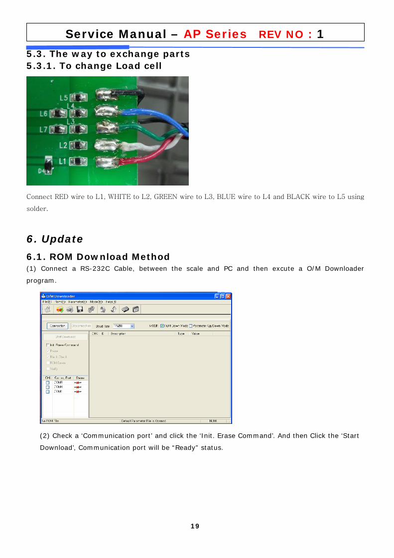
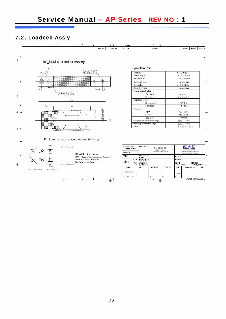
5.3. The way to exchange parts 5.3.1. To change Load cell
Connect RED wire to L1, WHITE to L2, GREEN wire to L3, BLUE wire to L4 and BLACK wire to L5 using
solder.
6. Update
6.1. ROM Download Method (1) Connect a RS-232C Cable, between the scale and PC and then excute a O/M Downloader
program.
(2) Check a ‘Communication port’ and click the ‘Init. Erase Command’. And then Click the ‘Start
Download’, Communication port will be “Ready” status.
20
Service Manual – AP Series REV NO : 1
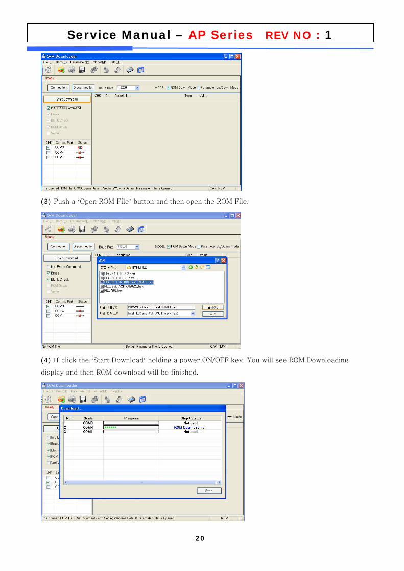
(3) Push a ‘Open ROM File’ button and then open the ROM File.
(4) If click the ‘Start Download’ holding a power ON/OFF key, You will see ROM Downloading
display and then ROM download will be finished.
21
Service Manual – AP Series REV NO : 1
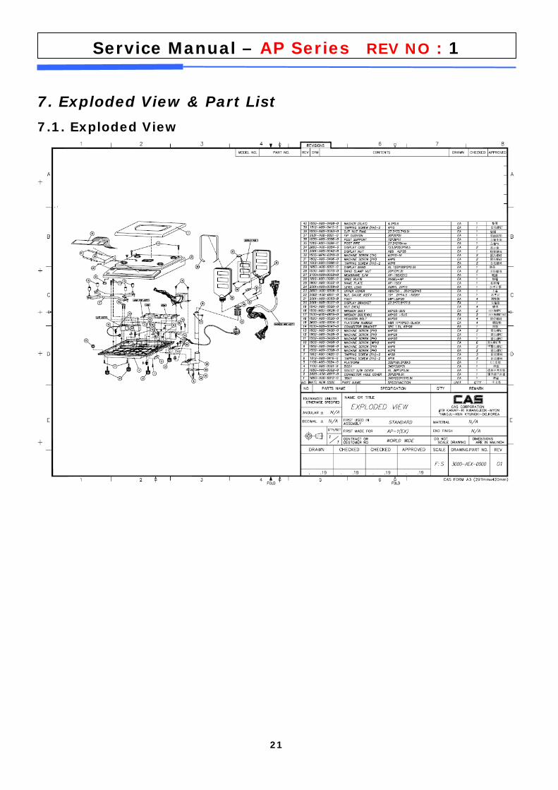
7. Exploded View & Part List
7.1. Exploded View
22
Service Manual – AP Series REV NO : 1
7.2. Loadcell Ass’y
23
Service Manual – AP Series REV NO : 1
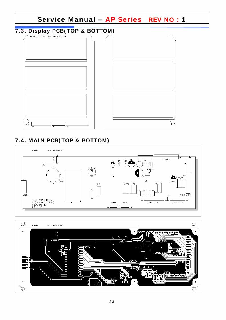
7.3. Display PCB(TOP & BOTTOM)
7.4. MAIN PCB(TOP & BOTTOM)
24
Service Manual – AP Series REV NO : 1
7.5. SCALE DIMENSION
25
Service Manual – AP Series REV NO : 1
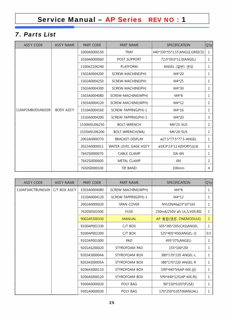
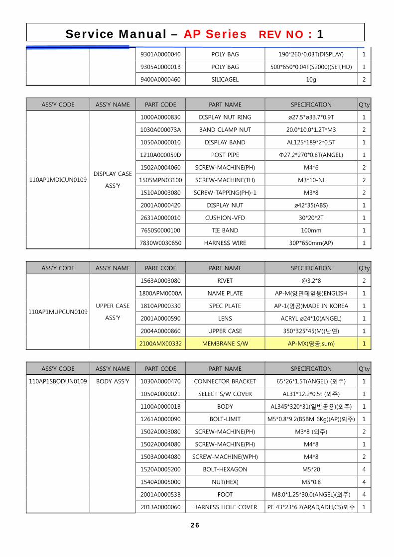
7. Parts List
ASS'Y CODE ASS'Y NAME PART CODE PART NAME SPECIFICATION Q'ty
1000A0000150 TRAY 440*330*55*1.5T(ANGLE,GREECE) 1
1030A0000060 POST SUPPORT 72.0*39.0*11.0(ANGEL) 1
1100AZ100240 PLATFORM ANGEL (일반) 샌딩 1
1502A0004200 SCREW-MACHINE(PH) M4*20 1
1502A0004250 SCREW-MACHINE(PH) M4*25 1
1502A0004300 SCREW-MACHINE(PH) M4*30 2
1503A0004080 SCREW-MACHINE(WPH) M4*8 1
1503A0004120 SCREW-MACHINE(WPH) M4*12 2
1510A0004160 SCREW-TAPPING(PH)-1 M4*16 2
1510A0004200 SCREW-TAPPING(PH)-1 M4*20 3
1530MSU06250 BOLT-WRENCH M6*25-SUS 2
1535MSU06200 BOLT-WRENCH(WA) M6*20-SUS 2
2001A0000370 BRACKET-DISPLAY ø27.5*77.5*77.5-ANGEL 1
2022A0000011 WATER LEVEL GAGE ASS'Y ø18.9*23*12.6(IVORY)상보 1
7642S0000070 CABLE CLAMP DA-6N 1
7642S0000600 METAL CLAMP 6N 2
110AP1MBODUN0109 BODY ASS'Y
7650S0000100 TIE BAND 100mm 4
ASS'Y CODE ASS'Y NAME PART CODE PART NAME SPECIFICATION Q'ty
1503A0004080 SCREW-MACHINE(WPH) M4*8 1
1510A0004120 SCREW-TAPPING(PH)-1 M4*12 1
2002A0000020 SPAN COVER NYLON#6ø23*10*165 1
7620S0502500 FUSE 250mA/250V ø5 UL,S,VDE,BSI 1
9002AP200330 MANUAL AP 통합(영문, ONEMODULE) 1
9100AP001330 C/T BOX 505*385*205(CAS)ANGEL 1
9100AP002300 C/T BOX 525*405*450(ANGEL-2) 0.5
9102AP001000 PAD 495*375(ANGEL) 1
9201AS200020 STYROFOAM PAD 155*100*20t 1
9203AS00004A STYROFOAM BOX 380*170*220 ANGEL-L 1
9203AS00005A STYROFOAM BOX 380*170*220 ANGEL-R 1
9206AS000110 STYROFOAM BOX 599*440*54(AP-MX,상) 1
9206AS000120 STYROFOAM BOX 599*440*125(AP-MX,하) 1
9300A0000020 POLY BAG 90*150*0.05T(FUSE) 1
110AP1MCTBUN0109 C/T BOX ASS'Y
9301A0000030 POLY BAG 170*250*0.05T(MANUAL) 1
26
Service Manual – AP Series REV NO : 1
9301A0000040 POLY BAG 190*260*0.03T(DISPLAY) 1
9305A000001B POLY BAG 500*650*0.04T(S2000)(SET,HD) 1
9400A0000460 SILICAGEL 10g 2
ASS'Y CODE ASS'Y NAME PART CODE PART NAME SPECIFICATION Q'ty
1000A0000830 DISPLAY NUT RING ø27.5*ø33.7*0.9T 1
1030A000073A BAND CLAMP NUT 20.0*10.0*1.2T*M3 2
1050A0000010 DISPLAY BAND AL125*189*2*0.5T 1
1210A000059D POST PIPE Φ27.2*270*0.8T(ANGEL) 1
1502A0004060 SCREW-MACHINE(PH) M4*6 2
1505MPN03100 SCREW-MACHINE(TH) M3*10-NI 2
1510A0003080 SCREW-TAPPING(PH)-1 M3*8 2
2001A0000420 DISPLAY NUT ø42*35(ABS) 1
2631A0000010 CUSHION-VFD 30*20*2T 1
7650S0000100 TIE BAND 100mm 1
110AP1MDICUN0109 DISPLAY CASE
ASS'Y
7830W0030650 HARNESS WIRE 30P*650mm(AP) 1
ASS'Y CODE ASS'Y NAME PART CODE PART NAME SPECIFICATION Q'ty
1563A0003080 RIVET @3.2*8 2
1800APM0000A NAME PLATE AP-M(양면테잎용)ENGLISH 1
1810AP000330 SPEC PLATE AP-1(영공)MADE IN KOREA 1
2001A0000590 LENS ACRYL ø24*10(ANGEL) 1
2004A0000860 UPPER CASE 350*325*45(M)(난연) 1
110AP1MUPCUN0109 UPPER CASE
ASS'Y
2100AMX00332 MEMBRANE S/W AP-MX(영공,sum) 1
ASS'Y CODE ASS'Y NAME PART CODE PART NAME SPECIFICATION Q'ty
1030A0000470 CONNECTOR BRACKET 65*26*1.5T(ANGEL) (외주) 1
1050A0000021 SELECT S/W COVER AL31*12.2*0.5t (외주) 1
1100A000001B BODY AL345*320*31(일반공용)(외주) 1
1261A0000090 BOLT-LIMIT M5*0.8*9.2(BSBM 6Kg)(AP)(외주) 1
1502A0003080 SCREW-MACHINE(PH) M3*8 (외주) 2
1502A0004080 SCREW-MACHINE(PH) M4*8 1
1503A0004080 SCREW-MACHINE(WPH) M4*8 2
1520A0005200 BOLT-HEXAGON M5*20 4
1540A0005000 NUT(HEX) M5*0.8 4
2001A000053B FOOT M8.0*1.25*30.0(ANGEL)(외주) 4
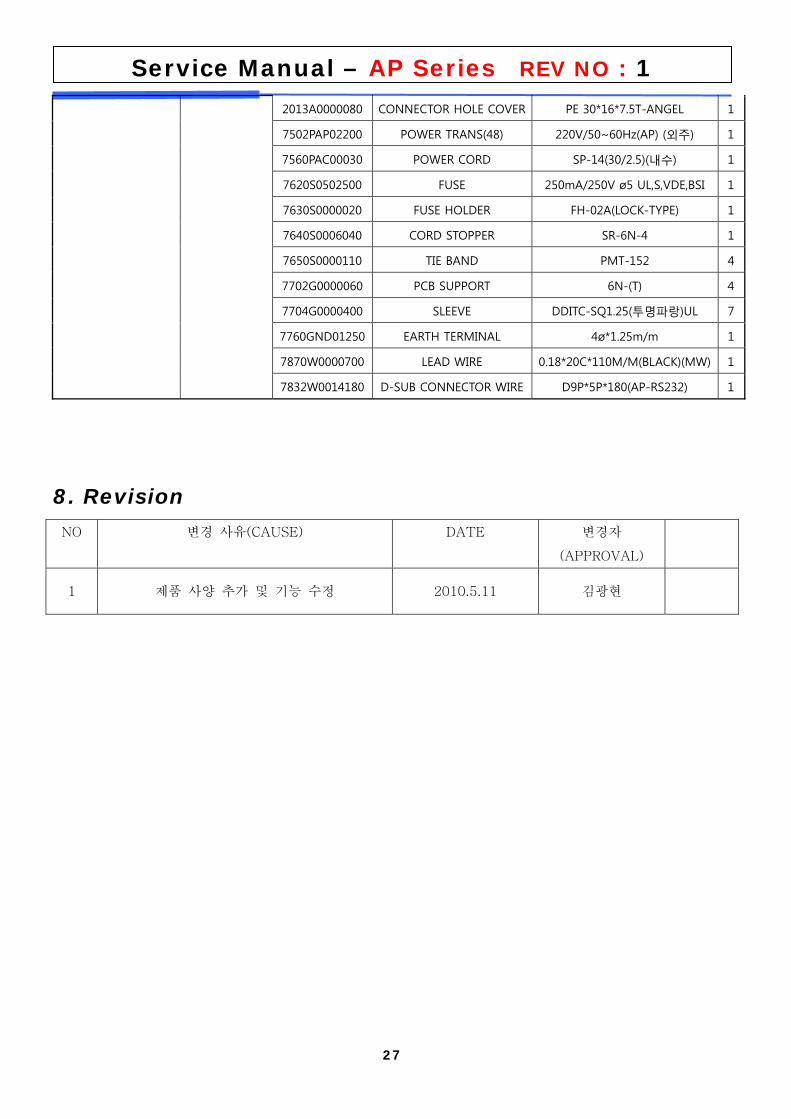
110AP1SBODUN0109 BODY ASS'Y
2013A0000060 HARNESS HOLE COVER PE 43*23*6.7(AP,AD,ADH,CS)외주 1
27
Service Manual – AP Series REV NO : 1
2013A0000080 CONNECTOR HOLE COVER PE 30*16*7.5T-ANGEL 1
7502PAP02200 POWER TRANS(48) 220V/50~60Hz(AP) (외주) 1
7560PAC00030 POWER CORD SP-14(30/2.5)(내수) 1
7620S0502500 FUSE 250mA/250V ø5 UL,S,VDE,BSI 1
7630S0000020 FUSE HOLDER FH-02A(LOCK-TYPE) 1
7640S0006040 CORD STOPPER SR-6N-4 1
7650S0000110 TIE BAND PMT-152 4
7702G0000060 PCB SUPPORT 6N-(T) 4
7704G0000400 SLEEVE DDITC-SQ1.25(투명파랑)UL 7
7760GND01250 EARTH TERMINAL 4ø*1.25m/m 1
7870W0000700 LEAD WIRE 0.18*20C*110M/M(BLACK)(MW) 1
7832W0014180 D-SUB CONNECTOR WIRE D9P*5P*180(AP-RS232) 1
8. Revision
NO 변경 사유(CAUSE) DATE 변경자
(APPROVAL)
1 제품 사양 추가 및 기능 수정 2010.5.11 김광현