Embed Size (px)
Citation preview
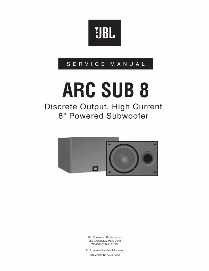
S E R V I C E M A N U A L
JBL Consumer Products Inc.250 Crossways Park Drive
Woodbury, N.Y. 11797
A Harman International Company
1112-ARCSUB8 Rev A 10/98
S E R V I C E M A N U A L
ARC SUB 8Discrete Output, High Current
8" Powered Subwoofer
1
Powered Subwoofer ARC SUB 8
TABLE OF CONTENTS
SPECIFICATIONS..........................................................1
WARRANTY ...................................................................2
SAFETY SYMBOLS.......................................................2
CONTROLS AND THEIR FUNCTION...........................3
TEST PROCEDURES....................................................4
TROUBLESHOOTING ...................................................5
ARC SUB 8 AMPLIFIER BLOCK DIAGRAM ................7
CABINET EXPLODED VIEW.........................................8
ARC SUB 8 ELECTRICAL PARTS LISTS....................9
ARC SUB 8 MECHANICAL PARTS LISTS ................10
PACKAGING EXPLODED VIEW.................................11
INTEGRATED CIRCUIT DIAGRAM ............................12
PRINTED CIRCUIT BOARD (TOP VIEW) ..................13
SCHEMATIC DIAGRAM 1 ...........................................14
SCHEMATIC DIAGRAM 2 ...........................................15
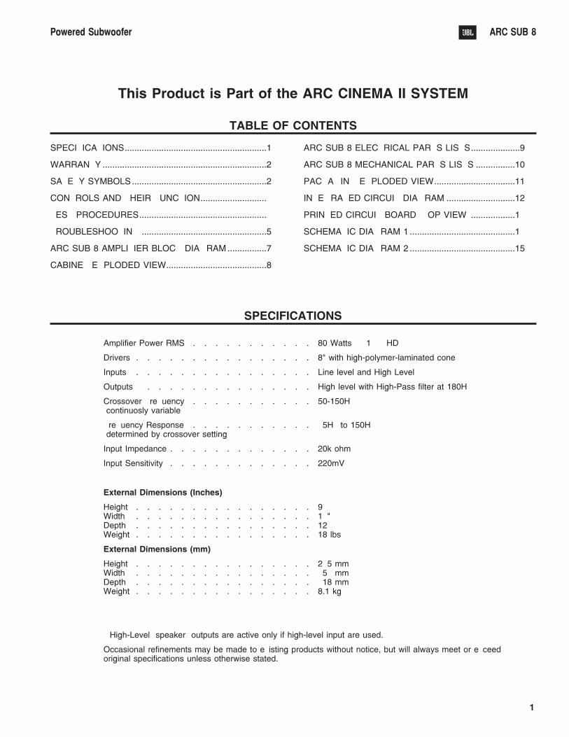
SPECIFICATIONS
Amplifier Power RMS . . . . . . . . . . . 80 Watts @ 1% THD
Drivers . . . . . . . . . . . . . . . . 8" with high-polymer-laminated cone
Inputs . . . . . . . . . . . . . . . . Line level and High Level
Outputs* . . . . . . . . . . . . . . . High level with High-Pass filter at 180Hz
Crossover Frequency . . . . . . . . . . . 50-150Hz(continuosly variable)
Frequency Response . . . . . . . . . . . 45Hz to 150Hz(determined by crossover setting)
Input Impedance . . . . . . . . . . . . . 20k ohm
Input Sensitivity . . . . . . . . . . . . . 220mV
External Dimensions (Inches)
Height . . . . . . . . . . . . . . . . 9 …Width . . . . . . . . . . . . . . . . 14"Depth . . . . . . . . . . . . . . . . 12 ‰Weight . . . . . . . . . . . . . . . . 18 lbs
External Dimensions (mm)
Height . . . . . . . . . . . . . . . . 235 mmWidth . . . . . . . . . . . . . . . . 356 mmDepth . . . . . . . . . . . . . . . . 318 mmWeight . . . . . . . . . . . . . . . . 8.1 kg
* High-Level (speaker) outputs are active only if high-level input are used.
Occasional refinements may be made to existing products without notice, but will always meet or exceedoriginal specifications unless otherwise stated.
This Product is Part of the ARC CINEMA II SYSTEM
2
Powered Subwoofer ARC SUB 8
WARRANTY
This amplifier is warranted against defects in material and
workmanship for a period of 90 days from date of shipment,
when installed in accordance with the owners manual in a
clean, dry, interior home environment. THIS AMPLIFIER IS
NOT SUITABLE FOR OPERATION OUTSIDE OR IN HARSH
ENVIRONMENTS. During the warranty period, the
manufacturer will, at its option, either repair of replace products
which prove to be defective.
For warranty service or repair, this product must be properly
packed and returned to a service facility designated by the
manufacturer. Buyer shall prepay shipping charges to the
designated facility and the manufacturer shall pay shipping
charges to return the product to buyer. However, Buyer shall
pay all shipping charges, duties and taxes for products
returned to the manufacturer from another country.
The manufacturer does not warrant that the operation of the
product will be uninterrupted or error-free. The Buyer must
determine the suitability of the product for his or her purposes.
LIMITATION OF WARRANTY
The foregoing warranty shall not apply to defects resulting from
improper or inadequate maintenance by Buyer, Buyer-supplied
interfacing, unauthorized modification or misuse, operation
outside of the environment specifications for the product
including inadequate ventilation, or improper site preparation,
installation, or maintenance.
NO OTHER WARRANTY IS EXPRESSED OR IMPLIED. THE
MANUFACTURER SPECIFICALLY DISCLAIMS THE
IMPLIED WARRANTIES OF MERCHANTABILITY AND
FITNESS FOR A PARTICULAR PURPOSE.
EXCLUSIVE REMEDIES
THE REMEDIES PROVIDED HEREIN ARE BUYERS SOLE
AND EXCLUSIVE REMEDIES. THE MANUFACTURER
SHALL NOT BE LIABLE FOR ANY DIRECT, INDIRECT,
SPECIAL, INCIDENTAL, OR CONSEQUENTIAL DAMAGES,
WHETHER BASED ON CONTRACT, TORT, OR ANY OTHER
LEGAL THEORY.
SAFETY SYMBOLS
The following symbols are used throughout this manual and in
the product. Familiarize yourself with each of the symbols and
its meaning before servicing this amplifier.
Instruction manual symbol. The product will be
marked with this symbol when it is necessary for the
user to refer to the instruction manual in order to
protect the unit against damage.
Indicates dangerous voltages are present. Be
extremely careful.
The CAUTION sign denoted a hazard. It calls
attention to a procedure which, if not
correctly performed or adhered to,
cou ld resu l t in damage to or
destruction of the amplifier. Do not
proceed beyond a CAUTION sign until the indicated conditions
are fully understood and met.
The WARNING sign denotes a hazard. It calls attention to a
procedure which, if not correctly
performed or adhered to could result
in injury or loss of life. Do not
proceed beyond a WARNING sign
until the indicated conditions are fully understood and met.
GENERAL SAFETY CONSIDERATIONS
THIS UNIT DOES NOT HAVE A POWER SWITCH;
HAZARDOUS VOLTAGES ARE PRESENT WITHIN THE
UNIT WHENEVER IT IS PLUGGED IN.
There are voltages and hot components at many points in the
amplifier which can, if contacted, cause serious injury. Be
extremely careful. Any adjustments or service procedures that
require operation of the amplifier out of its enclosure should be
performed only by trained service personnel.
3
Powered Subwoofer ARC SUB 8
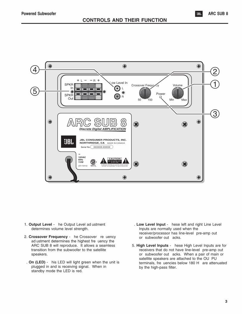
CONTROLS AND THEIR FUNCTION
1. Output Level - The Output Level adjustmentdetermines volume level strength.
2. Crossover Frequency - The Crossover Frequencyadjustment determines the highest frequency theARC SUB 8 will reproduce. It allows a seamlesstransition from the subwoofer to the satellitespeakers.
3. On (LED) - This LED will light green when the unit isplugged in and is receiving signal. When instandby mode the LED is red.
4. Low Level Input - These left and right Line LevelInputs are normally used when thereceiver/processor has line-level pre-amp out or subwoofer out jacks.
5. High Level Inputs - These High Level Inputs are forreceivers that do not have line-level pre-amp outor subwoofer out jacks. When a pair of main orsatellite speakers are attached to the OUTPUTterminals, frequencies below 180 Hz are attenuatedby the high-pass filter.
4
Powered Subwoofer ARC SUB 8
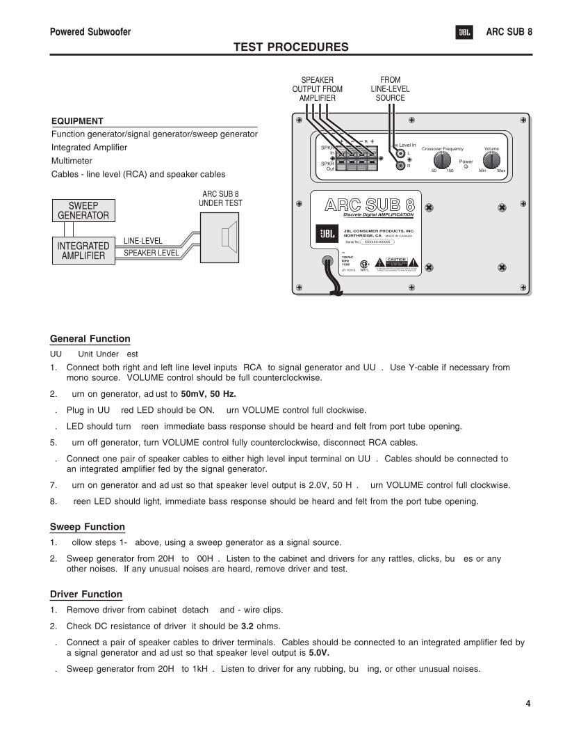
TEST PROCEDURES
General Function
UUT = Unit Under Test
1. Connect both right and left line level inputs (RCA) to signal generator and UUT. Use Y-cable if necessary frommono source. VOLUME control should be full counterclockwise.
2. Turn on generator, adjust to 50mV, 50 Hz.
3. Plug in UUT; red LED should be ON. Turn VOLUME control full clockwise.
4. LED should turn Green; immediate bass response should be heard and felt from port tube opening.
5. Turn off generator, turn VOLUME control fully counterclockwise, disconnect RCA cables.
6. Connect one pair of speaker cables to either high level input terminal on UUT. Cables should be connected toan integrated amplifier fed by the signal generator.
7. Turn on generator and adjust so that speaker level output is 2.0V, 50 Hz. Turn VOLUME control full clockwise.
8. Green LED should light, immediate bass response should be heard and felt from the port tube opening.
Sweep Function
1. Follow steps 1-4 above, using a sweep generator as a signal source.
2. Sweep generator from 20Hz to 300Hz. Listen to the cabinet and drivers for any rattles, clicks, buzzes or anyother noises. If any unusual noises are heard, remove driver and test.
Driver Function
1. Remove driver from cabinet; detach + and - wire clips.
2. Check DC resistance of driver; it should be 3.2 ohms.
3. Connect a pair of speaker cables to driver terminals. Cables should be connected to an integrated amplifier fed bya signal generator and adjust so that speaker level output is 5.0V.
4. Sweep generator from 20Hz to 1kHz. Listen to driver for any rubbing, buzzing, or other unusual noises.
5
Powered Subwoofer ARC SUB 8
1. TROUBLE SHOOTING BEFORE OPENING
Check connections, control settings, driver and other possible
external problems. If there is Output, determine if all controls
and Inputs function properly. Rotate Pots over full range while
applying lateral and vertical oscillating forces to locate possible
intermittent function. High Level Inputs should be tested
individually both differentially (signal from "-" to "+" with normal
output) and in common mode (signal from low level ground to
both "+" and "-" shorted together, giving virtually no output).
While passing a signal, corner drop the enclosure a few inches
to expose possible intermittent problems. Check woofer for
rubbing of voice coil or tears in cone or surround. Check
cabinet for loose extraneous articles which may have been
pushed into front port.
2. REMOVING THE AMPLIFIER.
There are voltages and hot components at many points in the
amplifier which can, if contacted, cause personal injury. Be
extremely careful. Any adjustments or service procedures that
require operation of the amplifier out of its enclosure should be
performed only by trained service personnel. Refer to PCB
drawings for locations of hazards and familiarize yourself with
their locations before starting.
A. Remove the subwoofer grille.
B. Remove the (4) 1 Black PPH screws attaching the
woofer to the cabinet.
C. Remove the woofer, unplug the two connecting
wires.
D. Remove the (8) ¾ screws black pph screws
attaching the ampifier assembly to the cabinet.
E. Remove the ampifier assembly.
F. For access to the input panel, first remove the three
outer screws. Remove knob and nuts from
potentiometers. Cut away the sealant securing the
cover to the faceplate. The input PCB should now
pull out completely.
3. TROUBLE SHOOTING AFTER REMOVAL
Verify AC plug is disconnected. See WARNINGS in section 2.
To prevent loose hardware from reducing safety spacings, it is
essential that all hardware be replaced in the same manner as
it was removed, with lock washers under all nuts, proper torque
on screws and thread locking sealer on the transformer nuts.
If line core or strain relief are replaced, it is necessary to seal
them completely to panel with an approved conformal coating
to prevent air "whistling" through any openings from woofer
pressure.
To reduce the risk or electric shock and/or fire,
replace items as marked on schematic with the
safety marking only with the exact replacements
listed in the safety component list, section 4. If
exact replacements are not available, order them from the
factory or an authorized service center.
A. Check fuse F1. If blown visually check transformer
for discoloration, and large capacitors (C1, C2) for
bulges or venting. Check for shorts with an
Ohmmeter, (see schematic).
B. With ohmmeter, verify voice coil of woofer is
3.2 ohms, and windings of transformer are
continuous.
C. Examine board and wiring for obvious damage,
broken or poorly soldered connections, or
discoloration.
D. Repair or replace items identified above.
E. For live power testing, attach a 4 ohm 100 watt
resistor to the output wires.
F. If the LED is not on, check for fuse continuity and
then for cold solder joints on CMC1 and bridge
diode.
G. With a signal present at the input, the output to the
power amp is at pin #8 of U1. If the signal is not
present at pin 8, there is a problem with preamp
section. Most likely, a cold solder joint will be the
problem. Track back the signal path to locate
problem.
CAUTIONS AND WARNINGS
BEFORE THIS AMPLIFIER IS PLUGGED IN, make sure its rated voltage corresponds to the voltage of the AC power source
to be employed. Failure to use the correct voltage could cause damage to the amplifier when the AC power cable is
plugged in. Do not exceed the rated voltage by more than 10%; operation below 90% will degrade performance or cause the
unit to shut off.
6
Powered Subwoofer ARC SUB 8
H. If signal present at pin 8, but still no sound, check
for cold solder joints on all power resistors, R4a and
R4b and the the power amp module. If C24 is
blown, C6 is not soldered or is defective. Check the
signal at R2. On the down signal side, the voltage
signal should be very small. If signal is similar on
both sides of R2, the amp module is likely defective.
I. If you hear a mechanical clicking noise from the amp
module, this indicates that the short circuit protection
has been engaged. Check that Q3, Q4 and Q5 are
soldered correctly. Also check that Q3 is not shorted
to power amp case.
J. If you have to replace the power module, be very,
very patient with the solder removal from this single
sided PCB. COMPLETELY REMOVE SOLDER
BEFORE TRYING TO REMOVE THE MODULE!
K. Assembly notes. Top side soldering as below:
J5: solder both ends
J3: solder both ends
J1: solder both ends
R48: solder GND end
At junction of C7a/C7b: Pin to GND
Crossover pot Gnd wire from PDB pad to POT
barrel. (Only physical contact required between
pot body and faceplate).
After repair, inspect for possible safety hazards, including
loose hardware, missing lock washers, correct fuse and lead
dress of primary wires (these must be held in position with
cable ties so that they cannot touch secondary components).
With ohmmeter, check that panel is connected to signal
ground.
It is essential that the following safety insulation test be
performed prior to returning the Power Sub-Woofer to the
customer, using one of the following methods.
A) Insulation Resistance Test
With a 500VDC Insulation Tester, Checkinsulation from the outer metal contact of theRCA jack (chassis) to the line neutral of AC
cord. Resistance should be >100MΩ.
B) Hi-Pot Test
If a UL approved Hi-Pot tester is available, testline & neutral of AC cord to outer shell of RCAjack (chassis) at 1100VAC for 2 seconds.
Observe all of instrument manufacturer’sinstructions and safety warnings in performingthis test.
Connect sub-woofer system to a music source. Play at high
level while checking for air leaks around panel edge, driver,
panel jacks and controls, and voice coil problems such as
rubbing or loose turns. With the crossover "frequency" set to
50Hz, very little of the voice content should be heard.
4. REASSEMBLY
Follow all disassembly instructions in reverse order. If the
input plate has been removed, it must be re-sealed with a small
bead of silicon seal or air leaks may result.
5. LIST OF SAFETY COMPONENTSREQUIRING EXACT REPLACEMENTS
F1 Fuse SLOW BLO 0.5A 250v T typeUL approved
CMC1 mc4438 Neosid 28-52, 2x 2.2mH#23 awg @ 2x 24
L1 mc4436 Neosid 32-19 200uH#18SNSR @36
T1 Transformer #4300, Use only factoryreplacement
PWR CORD SPT-2 better with polarized plug,UL appoved wired with the hot sideto fused side. Use with UL approvedpanel strain relief only.
BDR Bridge Rect. 200V 4A Use only factoryreplacement.
C1, 2 3300uF, 50V Electrolitic Radial.Be sure replacement part is at least thesame working voltage and capacitancerating. Also the lead spacing isimportant. Incorrect spacing maycause premature failure due to internalcabinet pressures and vibration.
C6 10u 50V Electrolytic Radial.
R29 470Ω 0.25 +-1% Metal
S53AMI Power Amp Module
7
Powered Subwoofer ARC SUB 8
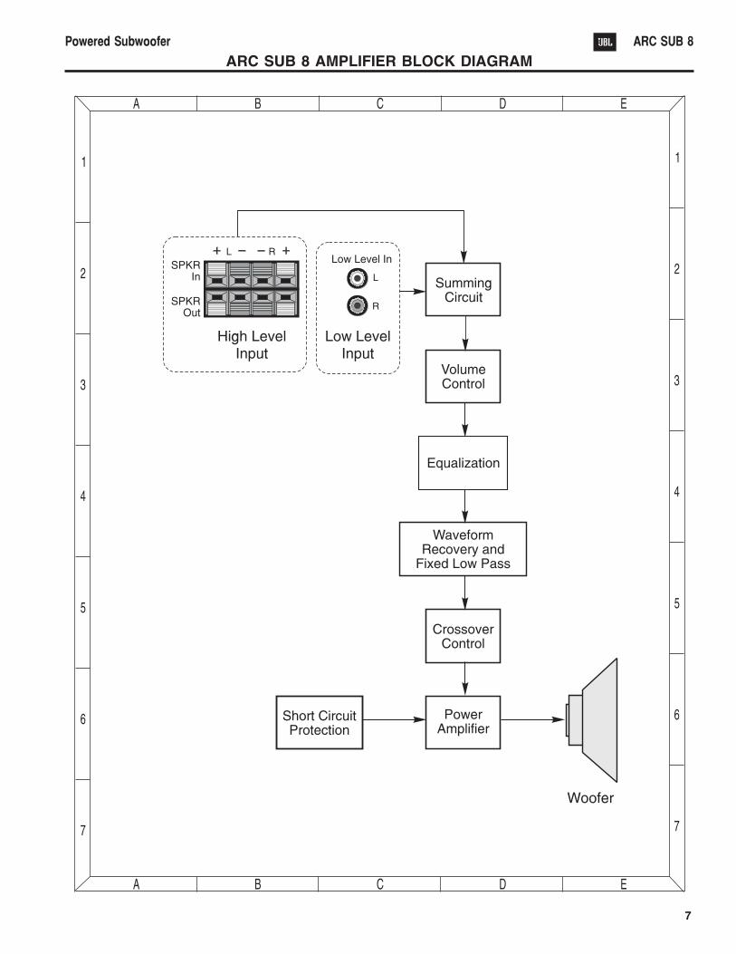
ARC SUB 8 AMPLIFIER BLOCK DIAGRAM
8
Powered Subwoofer ARC SUB 8
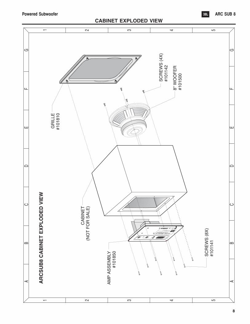
CABINET EXPLODED VIEW
Ref # Part # Description Qty.
Capacitors
C1, 2 30701 3300µF 50V +/-20% 2ELECTROLYTIC RADIAL
C3 30501 .1µF 50V +/-20% 1MONO-CERAMIC AXIAL
C4, 5, 9, 17, 24 30502 .1µF 50V +/-20% BIPOLAR 5MONO-CERAMIC
C6 30705 10µF 50V +/-20% BIPOLAR 1ELECTROLYTIC RADIAL
C7, 25 30503 .0022µF 50V +/-10% 2MONO-CERAMIC
C7A, 7B 30505 .1µF 100V +/-20% 2METAL POLYESTER RADIAL
C8, 10, 14, 18, 30504 .1µF 50V +/-10% 619, 20 MONO-CERAMIC
C11 30702 100µF 35V +/-20% 1ELECTROLYTIC RADIAL
C12 30703 4.7µF 35V +/-20% 1ELECTROLYTIC RADIAL
C13 30506 .001µF 50V +/-10% 1MONO-CERAMIC
C15, 16 30704 200.µF 50V +/-20% 2ELECTROLYTIC RADIALBIPOLAR
C21 30508 .01µF 50V +/-10% 1MONO-CERAMIC
C28 30507 .01µF 50V +/-20% 1MONO-CERAMIC
Diodes
DBR 50100 BRIDGE RECT 200W 4A 1
D1 50101 1N5256B 30V +/-5% 1/2W 1
D3 50102 1N4749A 24V +/-5% 1W 1
D6 50103 1N5234B 6.2V +/-5% 1/2W 1
D7, 8 50104 1N4148 100V +/-5% 0.1A 2
D9, 10 50105 1N4744A 15V +/-5% 1W 2
Resistors
R1 40403 2.2 Meg ohm 1/4W +/-5% 1CARBON FILM
R2 40408 8.45KΩ 1/4W +/-1% 1METAL FILM
R3 40412 33.2KΩ 1/4W +/-1% 1METAL FILM
R4A, 4B 40105 0.1Ω 1/2W +/-5% 2
R5, 6, 19 40420 1KΩ 1/4W +/-5% 3CARBON FILM
R7, 21, 44, 45 40409 10KΩ 1/4w +/-5% 4CARBON FILM
R8, 15, 34, 36, 40406 100KΩ 1/4W +/-5% 838, 42, 43, 57 CARBON FILM
R9 40421 3.9KΩ 5W +/-5% 13W CAN BE USED
R11, 12 40100 330Ω 1/2W +/-5% 2CARBON FILM
R10, 13 40404 1KΩ 2W +/-5% 2CARBON FILM
Ref # Part # Description Qty.
R14, 20 40405 4.7KΩ 1/4W +/-5% 2CARBON FILM
R16, 17 40101 820Ω 2W +/-5% 2CARBON FILM
R18 40407 220KΩ 1/4W +/-5% 1CARBON FILM
R22 40410 3.3K 1/4W +/-5% 1CARBON FILM
R26, 49 40701 1 Meg ohm 1/4W +/-5% 2CARBON FILM
R27 40411 24.9KΩ 1/4W +/-1% 1METAL FILM
R29 40103 470KΩ 1/4W +/-1% 1METAL
R30 40413 274KΩ 1/4W +/-1% 1METAL FILM
R31 40414 49.9KΩ 1/4W +/-1% 1METAL FILM
R32 40415 470KΩ 1/4W +/-5% 1CARBON FILM
R35 40416 221KΩ 1/4W +/-1% 1METAL FILM
R37 40417 47KΩ 1/4W +/-5% 1
CARBON FILM
R39 40418 22KΩ 1/4W +/-5% 1CARBON FILM
R40 1-114-154-24 150KΩ 1/4W +/-5% 1
R46 40104 4.7Ω 1/4W +/-5% 1CARBON FILM
R48 40419 6.04KΩ 1/4W +/-1% 1METAL FILM
R53, 54, 55, 56 40106 100Ω 2W +/-5% 4CARBON FILM
VR1 40401 100KΩ 1/4W +/-10% 1SINGLE LOG POT, FRQ POT
VR2 40402 5KΩ 1/4W +/-10% 1SINGLE LINEAR POT,VOL LEVEL POT
Integrated Circuit
U1 60100 LM324 QUAD OP-AMP +/-15 1
Transistors
Q1 60151 MPS A13 30 NPN(Darl) 1
Q2 60152 2N3906 40 PNP 1
Q3 60153 2N3904 40 NPN 1
Q4, 5 60154 MPS A56 80 PNP 2
Miscellaneous
CMC1 80100 mc4438 Neosid 28-52, 12x2.2mH #23awg @ 2X 24
L1 80101 mc4436 Neosid 32-19 1200uH #18SNSR @ 36
L2 80102 BL02RN2-R62 FERRITE BEAD 2
LED1 50106 DUAL CIR LED (2 LEGGED) 1
T1 80104 TRANSFORMER #4300 1
U2 60301 S53AMI POWER AMP 1MODULE
9
Powered Subwoofer ARC SUB 8
ARC SUB 8 ELECTRICAL PARTS LISTS
1 0
Powered Subwoofer ARC SUB 8
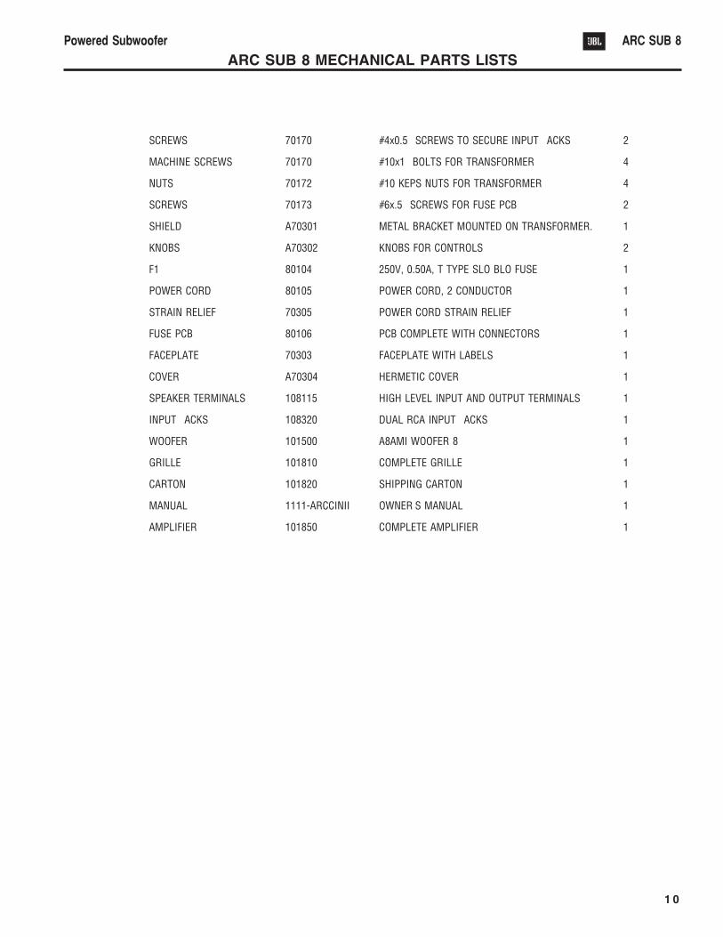
ARC SUB 8 MECHANICAL PARTS LISTS
Item Part # Discription Qty.
SCREWS 70170 #4x0.5 SCREWS TO SECURE INPUT JACKS 2
MACHINE SCREWS 70170 #10x1 BOLTS FOR TRANSFORMER 4
NUTS 70172 #10 KEPS NUTS FOR TRANSFORMER 4
SCREWS 70173 #6x.5 SCREWS FOR FUSE PCB 2
SHIELD A70301 METAL BRACKET MOUNTED ON TRANSFORMER. 1
KNOBS A70302 KNOBS FOR CONTROLS 2
F1 80104 250V, 0.50A, T TYPE SLO BLO FUSE 1
POWER CORD 80105 POWER CORD, 2 CONDUCTOR 1
STRAIN RELIEF 70305 POWER CORD STRAIN RELIEF 1
FUSE PCB 80106 PCB COMPLETE WITH CONNECTORS 1
FACEPLATE 70303 FACEPLATE WITH LABELS 1
COVER A70304 HERMETIC COVER 1
SPEAKER TERMINALS 108115 HIGH LEVEL INPUT AND OUTPUT TERMINALS 1
INPUT JACKS 108320 DUAL RCA INPUT JACKS 1
WOOFER 101500 A8AMI WOOFER 8 1
GRILLE 101810 COMPLETE GRILLE 1
CARTON 101820 SHIPPING CARTON 1
MANUAL 1111-ARCCINII OWNERS MANUAL 1
AMPLIFIER 101850 COMPLETE AMPLIFIER 1
1 1
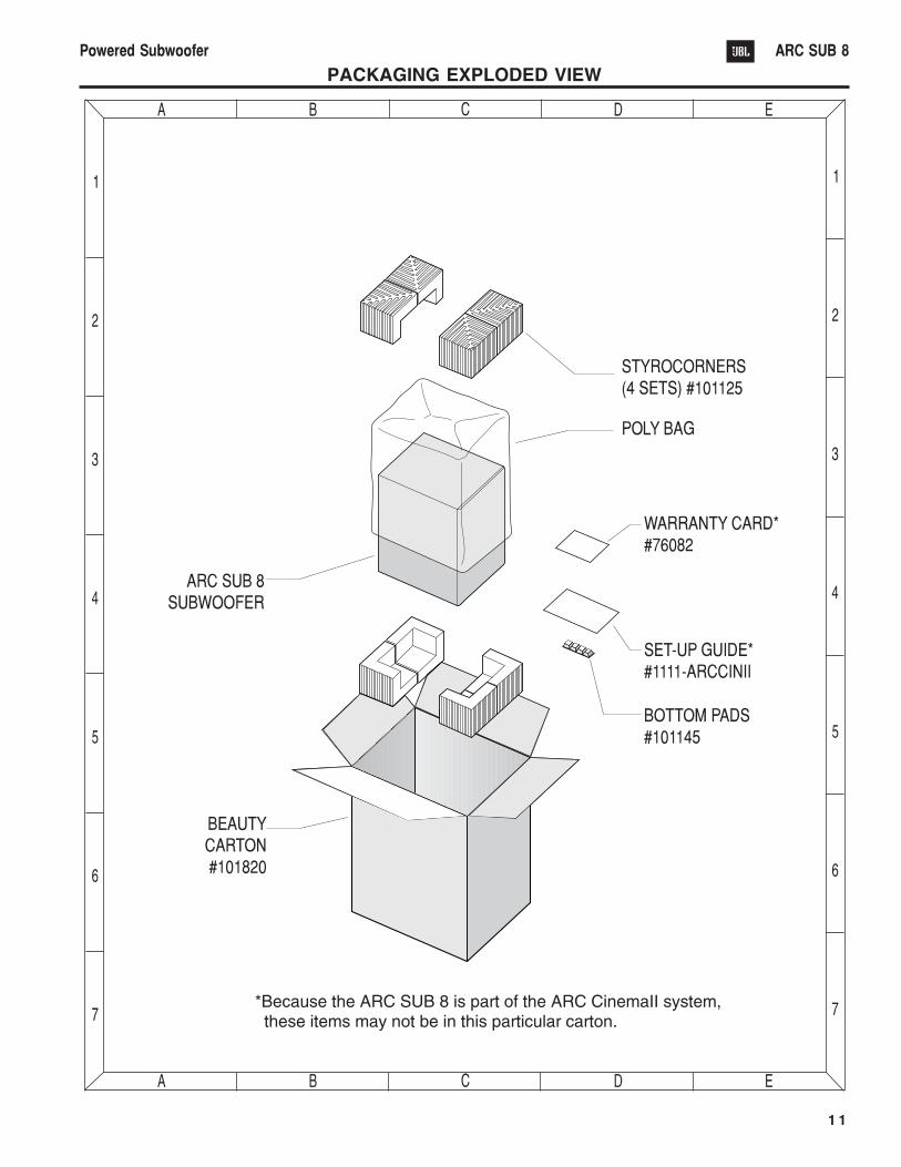
Powered Subwoofer ARC SUB 8
PACKAGING EXPLODED VIEW

1 2
Powered Subwoofer ARC SUB 8
INTEGRATED CIRCUIT DIAGRAM
1 3
Powered Subwoofer ARC SUB 8
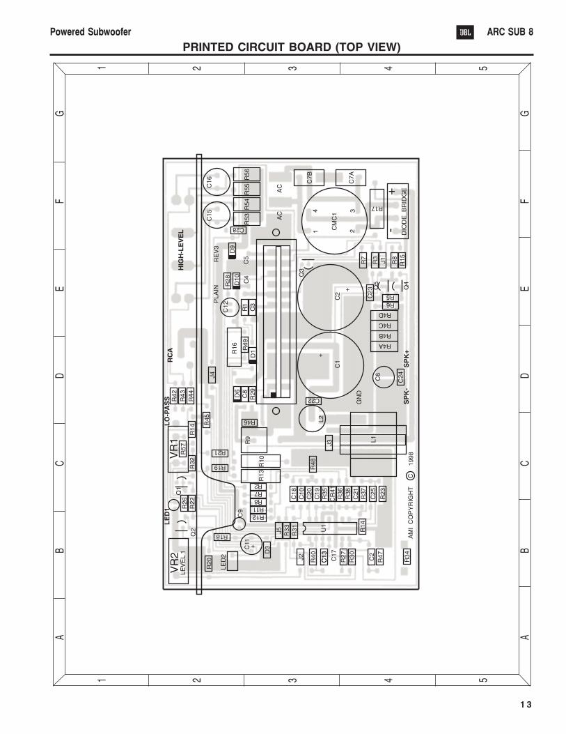
PRINTED CIRCUIT BOARD (TOP VIEW)
1 4
Powered Subwoofer ARC SUB 8
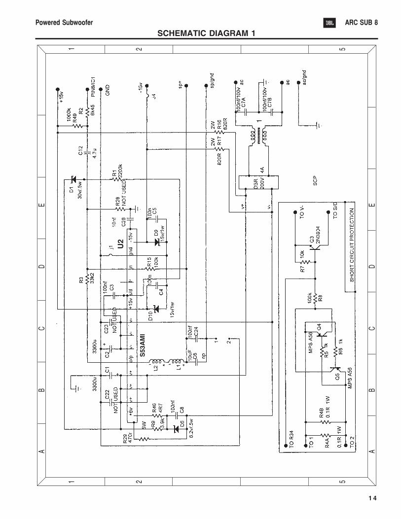
SCHEMATIC DIAGRAM 1
55
44
33
22
11
A A
B B
C C
D D
E E
F F
G G
S5
3A
MI
U2
T1
1 5
Powered Subwoofer ARC SUB 8
55
44
33
22
11
A A
B B
C C
D D
E E
F F
G G
U1
a
U1
d
U1
b
U1
c
2N
390
610
0K
6.0
4K
15
0K
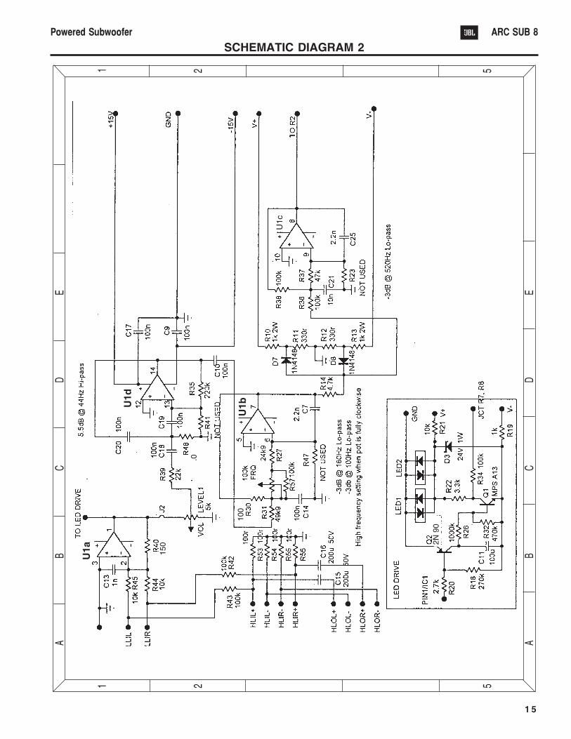
SCHEMATIC DIAGRAM 2