Embed Size (px)
Citation preview
Service Manual
[Applied Models] Inverter Pair : Heat Pump
Inverter PairWall Mounted Type FTXM-K Series
SiBE041434E
SiBE041434E
Inverter PairWall Mounted Type
FTXM-K SeriesHeat Pump
Indoor UnitFTXM20K3V1BFTXM25K3V1BFTXM35K3V1BFTXM42K3V1BFTXM50K3V1B
Outdoor UnitRXM20LV1BRXM25LV1BRXM35LV1BRXM42LV1BRXM50LV1B
i Table of Contents
SiBE041434E
1. Safety Cautions.......................................................................................v1.1 Warnings and Cautions Regarding Safety of Workers.............................v1.2 Warnings and Cautions Regarding Safety of Users................................ xi
2. Used Icons ........................................................................................... xiv
Part 1 List of Functions ................................................................11. Functions.................................................................................................2
Part 2 Specifications ....................................................................31. Specifications ..........................................................................................4
Part 3 Printed Circuit Board Connector Wiring Diagram .............71. Indoor Unit...............................................................................................8
1.1 20/25 Class ..............................................................................................81.2 35/42/50 Class .......................................................................................10
2. Outdoor Unit..........................................................................................122.1 20/25/35 Class .......................................................................................122.2 42/50 Class ............................................................................................14
Part 4 Function and Control........................................................151. Main Functions......................................................................................16
1.1 Temperature Control ..............................................................................161.2 Frequency Principle................................................................................161.3 Airflow Direction Control.........................................................................181.4 Fan Speed Control for Indoor Unit .........................................................201.5 Program Dry Operation ..........................................................................211.6 Automatic Operation...............................................................................221.7 Thermostat Control.................................................................................231.8 NIGHT SET Mode ..................................................................................241.9 ECONO Operation .................................................................................241.10 INTELLIGENT EYE Operation (20/25 Class).........................................251.11 2-Area INTELLIGENT EYE Operation (35/42/50 Class) ........................261.12 Inverter POWERFUL Operation .............................................................281.13 Clock Setting ..........................................................................................291.14 WEEKLY TIMER Operation ...................................................................301.15 Other Functions......................................................................................36
2. Function of Thermistor ..........................................................................373. Control Specification .............................................................................38
3.1 Mode Hierarchy ......................................................................................383.2 Frequency Control..................................................................................383.3 Controls at Mode Changing / Start-up....................................................403.4 Discharge Pipe Temperature Control.....................................................423.5 Input Current Control..............................................................................433.6 Freeze-up Protection Control .................................................................443.7 Heating Peak-cut Control .......................................................................443.8 Outdoor Fan Control...............................................................................453.9 Liquid Compression Protection Function................................................453.10 Defrost Control .......................................................................................463.11 Electronic Expansion Valve Control .......................................................47
Table of Contents ii
SiBE041434E
3.12 Malfunctions ...........................................................................................50
Part 5 Remote Controller ............................................................511. 20/25 Class ...........................................................................................522. 35/42/50 Class ......................................................................................54
Part 6 Service Diagnosis.............................................................561. General Problem Symptoms and Check Items .....................................572. Troubleshooting with LED .....................................................................58
2.1 Indoor Unit..............................................................................................582.2 Outdoor Unit ...........................................................................................58
3. Service Diagnosis .................................................................................594. Troubleshooting ....................................................................................62
4.1 Error Codes and Description ..................................................................624.2 Indoor Unit PCB Abnormality .................................................................634.3 Freeze-up Protection Control / Heating Peak-cut Control ......................644.4 Fan Motor (DC Motor) or Related Abnormality.......................................654.5 Thermistor or Related Abnormality (Indoor Unit)....................................684.6 Refrigerant Shortage ..............................................................................694.7 Low-voltage Detection or Over-voltage Detection..................................714.8 Signal Transmission Error (Between Indoor Unit and Outdoor Unit)......734.9 Unspecified Voltage (Between Indoor Unit and Outdoor Unit) ...............754.10 Outdoor Unit PCB Abnormality...............................................................764.11 OL Activation (Compressor Overload) ...................................................784.12 Compressor Lock ...................................................................................804.13 DC Fan Lock ..........................................................................................814.14 Input Overcurrent Detection ...................................................................824.15 Four Way Valve Abnormality..................................................................834.16 Discharge Pipe Temperature Control.....................................................854.17 High Pressure Control in Cooling ...........................................................864.18 Compressor System Sensor Abnormality ..............................................874.19 Position Sensor Abnormality ..................................................................884.20 DC Voltage / Current Sensor Abnormality (20/25/35 Class Only)..........904.21 Thermistor or Related Abnormality (Outdoor Unit) .................................914.22 Electrical Box Temperature Rise............................................................934.23 Radiation Fin Temperature Rise ............................................................944.24 Output Overcurrent Detection ................................................................95
5. Check ....................................................................................................975.1 Thermistor Resistance Check ................................................................975.2 Fan Motor Connector Output Check ......................................................985.3 Power Supply Waveforms Check...........................................................995.4 Electronic Expansion Valve Check.........................................................995.5 Four Way Valve Performance Check ...................................................1005.6 Inverter Unit Refrigerant System Check...............................................1005.7 Inverter Analyzer Check .......................................................................1015.8 Rotation Pulse Check on the Outdoor Unit PCB ..................................1025.9 Installation Condition Check.................................................................1035.10 Discharge Pressure Check...................................................................1045.11 Outdoor Fan System Check .................................................................1045.12 Main Circuit Short Check......................................................................105
iii Table of Contents
SiBE041434E
5.13 Power Module Check ...........................................................................106
Part 7 Trial Operation and Field Settings.................................1081. Pump Down Operation........................................................................1092. Forced Cooling Operation ...................................................................1103. Trial Operation ....................................................................................1114. Field Settings ......................................................................................112
4.1 When 2 Units are installed in 1 Room ..................................................1124.2 Model Type Setting ..............................................................................1124.3 Facility Setting (cooling at low outdoor temperature) ...........................1134.4 Jumper Settings ...................................................................................114
5. Silicon Grease on Power Transistor / Diode Bridge............................115
Part 8 Appendix.........................................................................1161. Piping Diagrams..................................................................................117
1.1 Indoor Unit............................................................................................1171.2 Outdoor Unit .........................................................................................119
2. Wiring Diagrams..................................................................................1202.1 Indoor Unit............................................................................................1202.2 Outdoor Unit .........................................................................................121
Table of Contents iv
Safety Cautions SiBE041434E
1. Safety CautionsBe sure to read the following safety cautions before conducting repair work.After the repair work is complete, be sure to conduct a test operation to ensure that the equipment operates normally, and explain the cautions for operating the product to the customer.
Caution Items The caution items are classified into Warning and Caution. The Warning items are especially important since they can lead to death or serious injury if they are not followed closely. The Caution items can also lead to serious accidents under some conditions if they are not followed. Therefore, be sure to observe all the safety caution items described below.
Pictograms This symbol indicates the item for which caution must be exercised. The pictogram shows the item to which attention must be paid.
This symbol indicates the prohibited action. The prohibited item or action is shown in the illustration or near the symbol.
This symbol indicates the action that must be taken, or the instruction. The instruction is shown in the illustration or near the symbol.
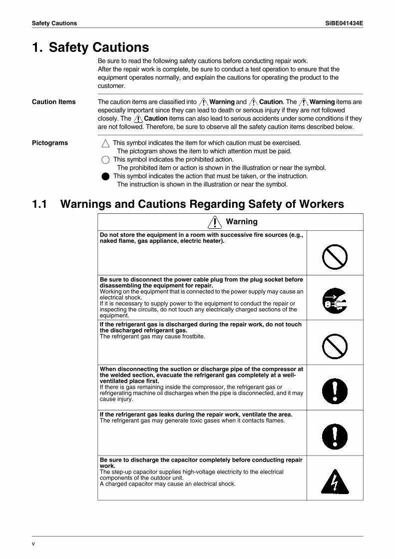
1.1 Warnings and Cautions Regarding Safety of WorkersWarning
Do not store the equipment in a room with successive fire sources (e.g., naked flame, gas appliance, electric heater).
Be sure to disconnect the power cable plug from the plug socket before disassembling the equipment for repair.Working on the equipment that is connected to the power supply may cause an electrical shock.If it is necessary to supply power to the equipment to conduct the repair or inspecting the circuits, do not touch any electrically charged sections of the equipment.
If the refrigerant gas is discharged during the repair work, do not touch the discharged refrigerant gas.The refrigerant gas may cause frostbite.
When disconnecting the suction or discharge pipe of the compressor at the welded section, evacuate the refrigerant gas completely at a well-ventilated place first.If there is gas remaining inside the compressor, the refrigerant gas or refrigerating machine oil discharges when the pipe is disconnected, and it may cause injury.
If the refrigerant gas leaks during the repair work, ventilate the area. The refrigerant gas may generate toxic gases when it contacts flames.
Be sure to discharge the capacitor completely before conducting repair work.The step-up capacitor supplies high-voltage electricity to the electrical components of the outdoor unit.A charged capacitor may cause an electrical shock.
v
SiBE041434E Safety Cautions
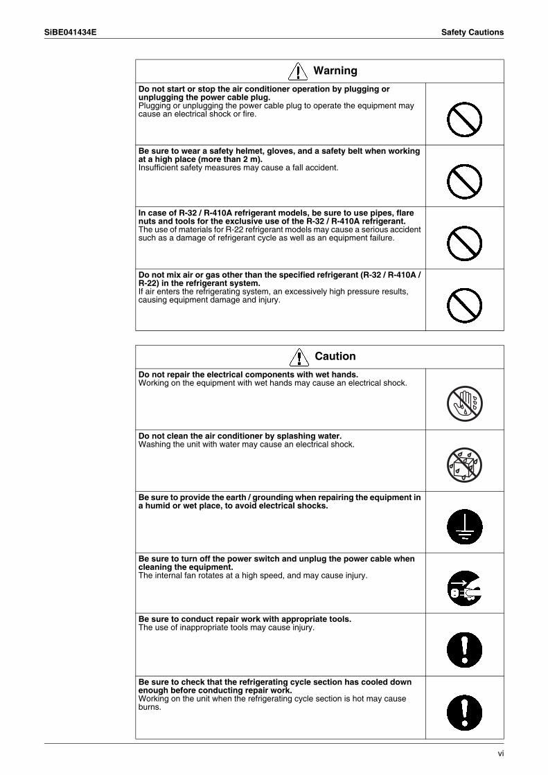
Do not start or stop the air conditioner operation by plugging or unplugging the power cable plug.Plugging or unplugging the power cable plug to operate the equipment may cause an electrical shock or fire.
Be sure to wear a safety helmet, gloves, and a safety belt when working at a high place (more than 2 m).Insufficient safety measures may cause a fall accident.
In case of R-32 / R-410A refrigerant models, be sure to use pipes, flare nuts and tools for the exclusive use of the R-32 / R-410A refrigerant.The use of materials for R-22 refrigerant models may cause a serious accident such as a damage of refrigerant cycle as well as an equipment failure.
Do not mix air or gas other than the specified refrigerant (R-32 / R-410A / R-22) in the refrigerant system.If air enters the refrigerating system, an excessively high pressure results, causing equipment damage and injury.
Warning
Caution
Do not repair the electrical components with wet hands.Working on the equipment with wet hands may cause an electrical shock.
Do not clean the air conditioner by splashing water.Washing the unit with water may cause an electrical shock.
Be sure to provide the earth / grounding when repairing the equipment in a humid or wet place, to avoid electrical shocks.
Be sure to turn off the power switch and unplug the power cable when cleaning the equipment.The internal fan rotates at a high speed, and may cause injury.
Be sure to conduct repair work with appropriate tools.The use of inappropriate tools may cause injury.
Be sure to check that the refrigerating cycle section has cooled down enough before conducting repair work.Working on the unit when the refrigerating cycle section is hot may cause burns.
vi
Safety Cautions SiBE041434E
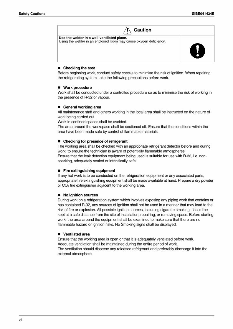
Checking the areaBefore beginning work, conduct safety checks to minimise the risk of ignition. When repairing the refrigerating system, take the following precautions before work.
Work procedureWork shall be conducted under a controlled procedure so as to minimise the risk of working in the presence of R-32 or vapour.
General working areaAll maintenance staff and others working in the local area shall be instructed on the nature of work being carried out.Work in confined spaces shall be avoided.The area around the workspace shall be sectioned off. Ensure that the conditions within the area have been made safe by control of flammable materials.
Checking for presence of refrigerantThe working area shall be checked with an appropriate refrigerant detector before and during work, to ensure the technician is aware of potentially flammable atmospheres.Ensure that the leak detection equipment being used is suitable for use with R-32, i.e. non-sparking, adequately sealed or intrinsically safe.
Fire extinguishing equipmentIf any hot work is to be conducted on the refrigeration equipment or any associated parts, appropriate fire extinguishing equipment shall be made available at hand. Prepare a dry powder or CO2 fire extinguisher adjacent to the working area.
No ignition sourcesDuring work on a refrigeration system which involves exposing any piping work that contains or has contained R-32, any sources of ignition shall not be used in a manner that may lead to the risk of fire or explosion. All possible ignition sources, including cigarette smoking, should be kept at a safe distance from the site of installation, repairing, or removing space. Before starting work, the area around the equipment shall be examined to make sure that there are no flammable hazard or ignition risks. No Smoking signs shall be displayed.
Ventilated areaEnsure that the working area is open or that it is adequately ventilated before work.Adequate ventilation shall be maintained during the entire period of work.The ventilation should disperse any released refrigerant and preferably discharge it into the external atmosphere.
Use the welder in a well-ventilated place.Using the welder in an enclosed room may cause oxygen deficiency.
Caution
vii
SiBE041434E Safety Cautions
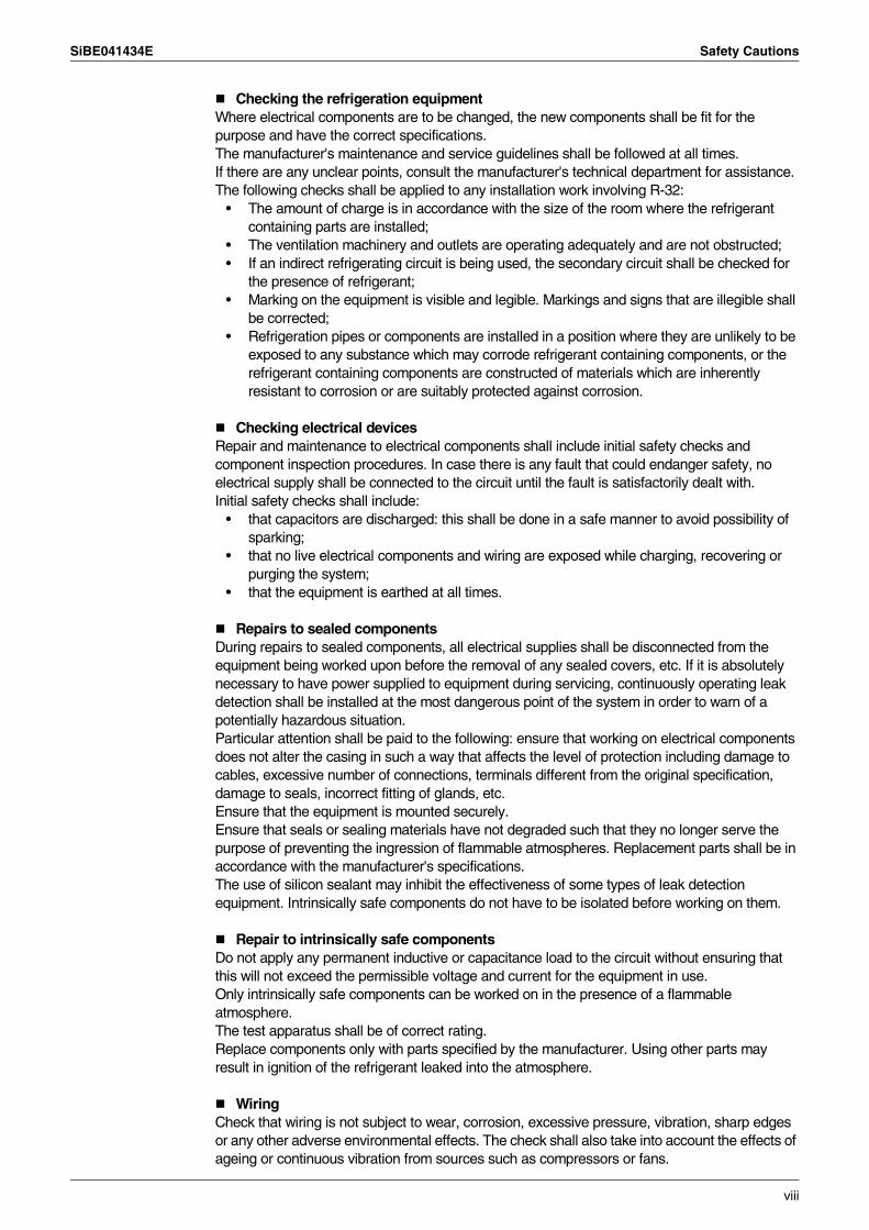
Checking the refrigeration equipmentWhere electrical components are to be changed, the new components shall be fit for the purpose and have the correct specifications.The manufacturer's maintenance and service guidelines shall be followed at all times.If there are any unclear points, consult the manufacturer's technical department for assistance.The following checks shall be applied to any installation work involving R-32:
• The amount of charge is in accordance with the size of the room where the refrigerant containing parts are installed;
• The ventilation machinery and outlets are operating adequately and are not obstructed;• If an indirect refrigerating circuit is being used, the secondary circuit shall be checked for
the presence of refrigerant;• Marking on the equipment is visible and legible. Markings and signs that are illegible shall
be corrected;• Refrigeration pipes or components are installed in a position where they are unlikely to be
exposed to any substance which may corrode refrigerant containing components, or the refrigerant containing components are constructed of materials which are inherently resistant to corrosion or are suitably protected against corrosion.
Checking electrical devicesRepair and maintenance to electrical components shall include initial safety checks and component inspection procedures. In case there is any fault that could endanger safety, no electrical supply shall be connected to the circuit until the fault is satisfactorily dealt with.Initial safety checks shall include:
• that capacitors are discharged: this shall be done in a safe manner to avoid possibility of sparking;
• that no live electrical components and wiring are exposed while charging, recovering or purging the system;
• that the equipment is earthed at all times.
Repairs to sealed componentsDuring repairs to sealed components, all electrical supplies shall be disconnected from the equipment being worked upon before the removal of any sealed covers, etc. If it is absolutely necessary to have power supplied to equipment during servicing, continuously operating leak detection shall be installed at the most dangerous point of the system in order to warn of a potentially hazardous situation.Particular attention shall be paid to the following: ensure that working on electrical components does not alter the casing in such a way that affects the level of protection including damage to cables, excessive number of connections, terminals different from the original specification, damage to seals, incorrect fitting of glands, etc.Ensure that the equipment is mounted securely.Ensure that seals or sealing materials have not degraded such that they no longer serve the purpose of preventing the ingression of flammable atmospheres. Replacement parts shall be in accordance with the manufacturer's specifications.The use of silicon sealant may inhibit the effectiveness of some types of leak detection equipment. Intrinsically safe components do not have to be isolated before working on them.
Repair to intrinsically safe componentsDo not apply any permanent inductive or capacitance load to the circuit without ensuring that this will not exceed the permissible voltage and current for the equipment in use.Only intrinsically safe components can be worked on in the presence of a flammable atmosphere.The test apparatus shall be of correct rating.Replace components only with parts specified by the manufacturer. Using other parts may result in ignition of the refrigerant leaked into the atmosphere.
WiringCheck that wiring is not subject to wear, corrosion, excessive pressure, vibration, sharp edges or any other adverse environmental effects. The check shall also take into account the effects of ageing or continuous vibration from sources such as compressors or fans.
viii
Safety Cautions SiBE041434E
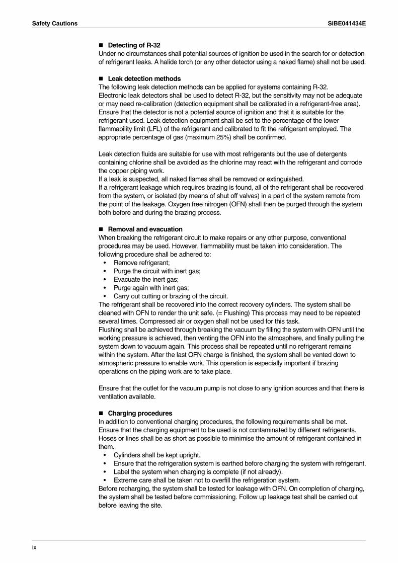
Detecting of R-32Under no circumstances shall potential sources of ignition be used in the search for or detection of refrigerant leaks. A halide torch (or any other detector using a naked flame) shall not be used.
Leak detection methodsThe following leak detection methods can be applied for systems containing R-32.Electronic leak detectors shall be used to detect R-32, but the sensitivity may not be adequate or may need re-calibration (detection equipment shall be calibrated in a refrigerant-free area). Ensure that the detector is not a potential source of ignition and that it is suitable for the refrigerant used. Leak detection equipment shall be set to the percentage of the lower flammability limit (LFL) of the refrigerant and calibrated to fit the refrigerant employed. The appropriate percentage of gas (maximum 25%) shall be confirmed.
Leak detection fluids are suitable for use with most refrigerants but the use of detergents containing chlorine shall be avoided as the chlorine may react with the refrigerant and corrode the copper piping work.If a leak is suspected, all naked flames shall be removed or extinguished.If a refrigerant leakage which requires brazing is found, all of the refrigerant shall be recovered from the system, or isolated (by means of shut off valves) in a part of the system remote from the point of the leakage. Oxygen free nitrogen (OFN) shall then be purged through the system both before and during the brazing process.
Removal and evacuationWhen breaking the refrigerant circuit to make repairs or any other purpose, conventional procedures may be used. However, flammability must be taken into consideration. The following procedure shall be adhered to:
• Remove refrigerant;• Purge the circuit with inert gas;• Evacuate the inert gas;• Purge again with inert gas;• Carry out cutting or brazing of the circuit.
The refrigerant shall be recovered into the correct recovery cylinders. The system shall be cleaned with OFN to render the unit safe. (= Flushing) This process may need to be repeated several times. Compressed air or oxygen shall not be used for this task.Flushing shall be achieved through breaking the vacuum by filling the system with OFN until the working pressure is achieved, then venting the OFN into the atmosphere, and finally pulling the system down to vacuum again. This process shall be repeated until no refrigerant remains within the system. After the last OFN charge is finished, the system shall be vented down to atmospheric pressure to enable work. This operation is especially important if brazing operations on the piping work are to take place.
Ensure that the outlet for the vacuum pump is not close to any ignition sources and that there is ventilation available.
Charging proceduresIn addition to conventional charging procedures, the following requirements shall be met.Ensure that the charging equipment to be used is not contaminated by different refrigerants. Hoses or lines shall be as short as possible to minimise the amount of refrigerant contained in them.
• Cylinders shall be kept upright.• Ensure that the refrigeration system is earthed before charging the system with refrigerant.• Label the system when charging is complete (if not already).• Extreme care shall be taken not to overfill the refrigeration system.
Before recharging, the system shall be tested for leakage with OFN. On completion of charging, the system shall be tested before commissioning. Follow up leakage test shall be carried out before leaving the site.
ix
SiBE041434E Safety Cautions
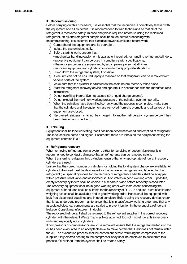
DecommissioningBefore carrying out this procedure, it is essential that the technician is completely familiar with the equipment and all its details. It is recommended to train technicians so that all of the refrigerant is recovered safely. In case analysis is required before re-using the reclaimed refrigerant, an oil and refrigerant sample shall be taken before proceeding with decommissioning. It is essential that electrical power is available before work.
a) Comprehend the equipment and its operation.b) Isolate the system electrically.c) Before starting work, ensure that:
• mechanical handling equipment is available if required, for handling refrigerant cylinders;• protective equipment can be used in compliance with specifications;• the recovery process is supervised by a competent person at all times;• recovery equipment and cylinders conform to the appropriate standards.
d) Pump down the refrigerant system, if possible.e) If vacuum can not be ensured, apply a manifold so that refrigerant can be removed from
various parts of the system.f) Make sure that the cylinder is situated on the scale before recovery takes place.g) Start the refrigerant recovery device and operate it in accordance with the manufacturer's
instructions.h) Do not overfill cylinders. (Do not exceed 80% liquid charge volume).i) Do not exceed the maximum working pressure of the cylinder, even temporarily.j) When the cylinders have been filled correctly and the process is completed, make sure
that the cylinders and the equipment are removed from site promptly and all valves on the equipment are closed.
k) Recovered refrigerant shall not be charged into another refrigeration system before it has been cleaned and checked.
LabellingEquipment shall be labelled stating that it has been decommissioned and emptied of refrigerant. The label shall be dated and signed. Ensure that there are labels on the equipment stating the equipment contains R-32.
Refrigerant recoveryWhen removing refrigerant from a system, either for servicing or decommissioning, it is recommended to conduct training so that all refrigerants can be removed safely.When transferring refrigerant into cylinders, ensure that only appropriate refrigerant recovery cylinders are used.Ensure that the correct number of cylinders for holding the total system charge are available. All cylinders to be used must be designated for the recovered refrigerant and labelled for that refrigerant (i.e. special cylinders for the recovery of refrigerant). Cylinders shall be equipped with a pressure relief valve and associated shut-off valves in good working order. If possible, empty recovery cylinders shall be cooled in a separate place before recovery is conducted.The recovery equipment shall be in good working order with instructions concerning the equipment at hand, and shall be suitable for the recovery of R-32. In addition, a set of calibrated weighing scales shall be available and in good working order. Hoses shall be equipped with leak-free disconnect couplings and in good condition. Before using the recovery device, check that it has undergone proper maintenance, that it is in satisfactory working order, and that any associated electrical components are sealed to prevent ignition in the event of a refrigerant leakage. Consult manufacturer if in doubt.The recovered refrigerant shall be returned to the refrigerant supplier in the correct recovery cylinder, with the relevant Waste Transfer Note attached. Do not mix refrigerants in recovery units and especially not in cylinders.If compressors or compressor oil are to be removed, ensure that the refrigerant melted into the oil has been evacuated to an acceptable level to make certain that R-32 does not remain within the oil. The evacuation process shall be carried out before returning the compressor to the supplier. Only electric heating to the compressor body shall be employed to accelerate this process. Oil drained from the system shall be treated safely.
x
Safety Cautions SiBE041434E
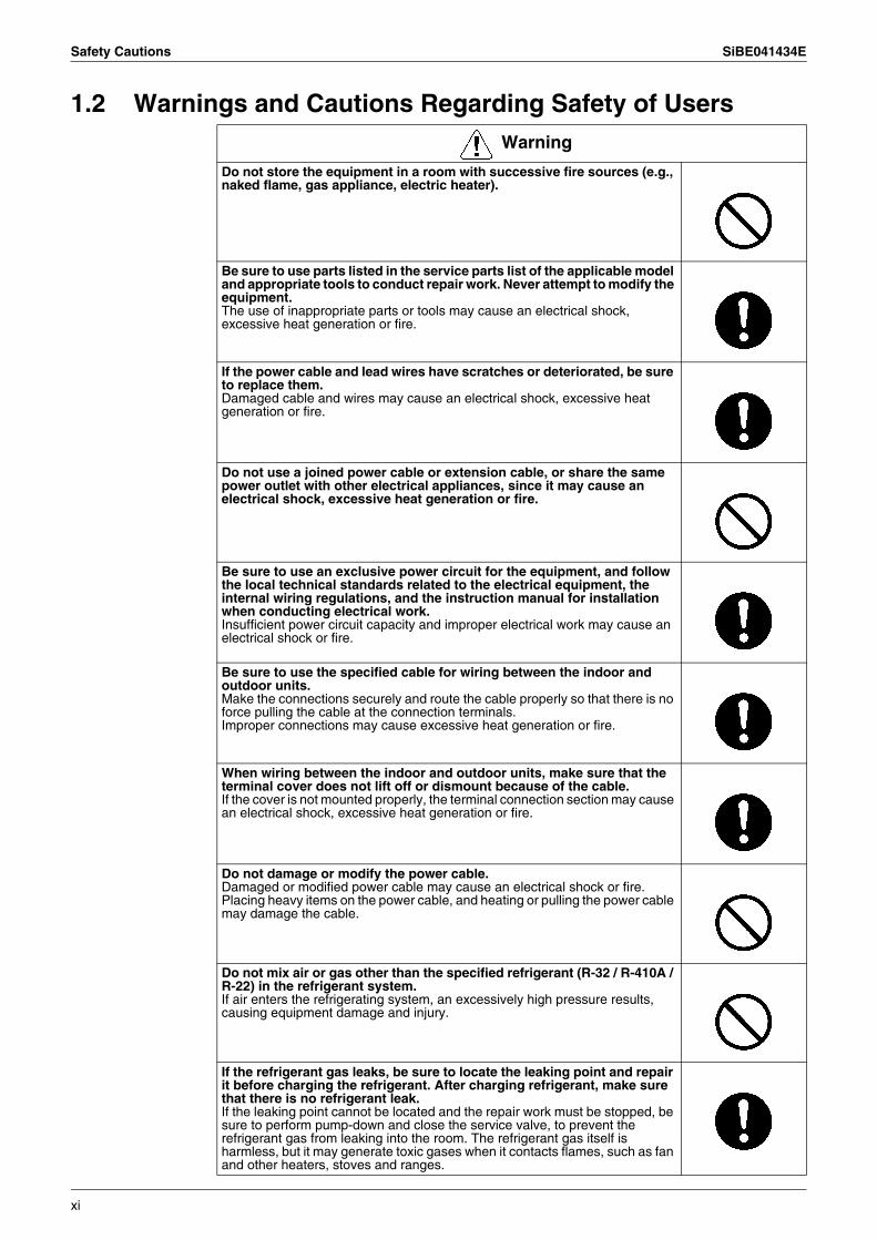
1.2 Warnings and Cautions Regarding Safety of UsersWarning
Do not store the equipment in a room with successive fire sources (e.g., naked flame, gas appliance, electric heater).
Be sure to use parts listed in the service parts list of the applicable model and appropriate tools to conduct repair work. Never attempt to modify the equipment.The use of inappropriate parts or tools may cause an electrical shock, excessive heat generation or fire.
If the power cable and lead wires have scratches or deteriorated, be sure to replace them.Damaged cable and wires may cause an electrical shock, excessive heat generation or fire.
Do not use a joined power cable or extension cable, or share the same power outlet with other electrical appliances, since it may cause an electrical shock, excessive heat generation or fire.
Be sure to use an exclusive power circuit for the equipment, and follow the local technical standards related to the electrical equipment, the internal wiring regulations, and the instruction manual for installation when conducting electrical work.Insufficient power circuit capacity and improper electrical work may cause an electrical shock or fire.
Be sure to use the specified cable for wiring between the indoor and outdoor units.Make the connections securely and route the cable properly so that there is no force pulling the cable at the connection terminals.Improper connections may cause excessive heat generation or fire.
When wiring between the indoor and outdoor units, make sure that the terminal cover does not lift off or dismount because of the cable.If the cover is not mounted properly, the terminal connection section may cause an electrical shock, excessive heat generation or fire.
Do not damage or modify the power cable.Damaged or modified power cable may cause an electrical shock or fire.Placing heavy items on the power cable, and heating or pulling the power cable may damage the cable.
Do not mix air or gas other than the specified refrigerant (R-32 / R-410A / R-22) in the refrigerant system.If air enters the refrigerating system, an excessively high pressure results, causing equipment damage and injury.
If the refrigerant gas leaks, be sure to locate the leaking point and repair it before charging the refrigerant. After charging refrigerant, make sure that there is no refrigerant leak.If the leaking point cannot be located and the repair work must be stopped, be sure to perform pump-down and close the service valve, to prevent the refrigerant gas from leaking into the room. The refrigerant gas itself is harmless, but it may generate toxic gases when it contacts flames, such as fan and other heaters, stoves and ranges.
xi
SiBE041434E Safety Cautions
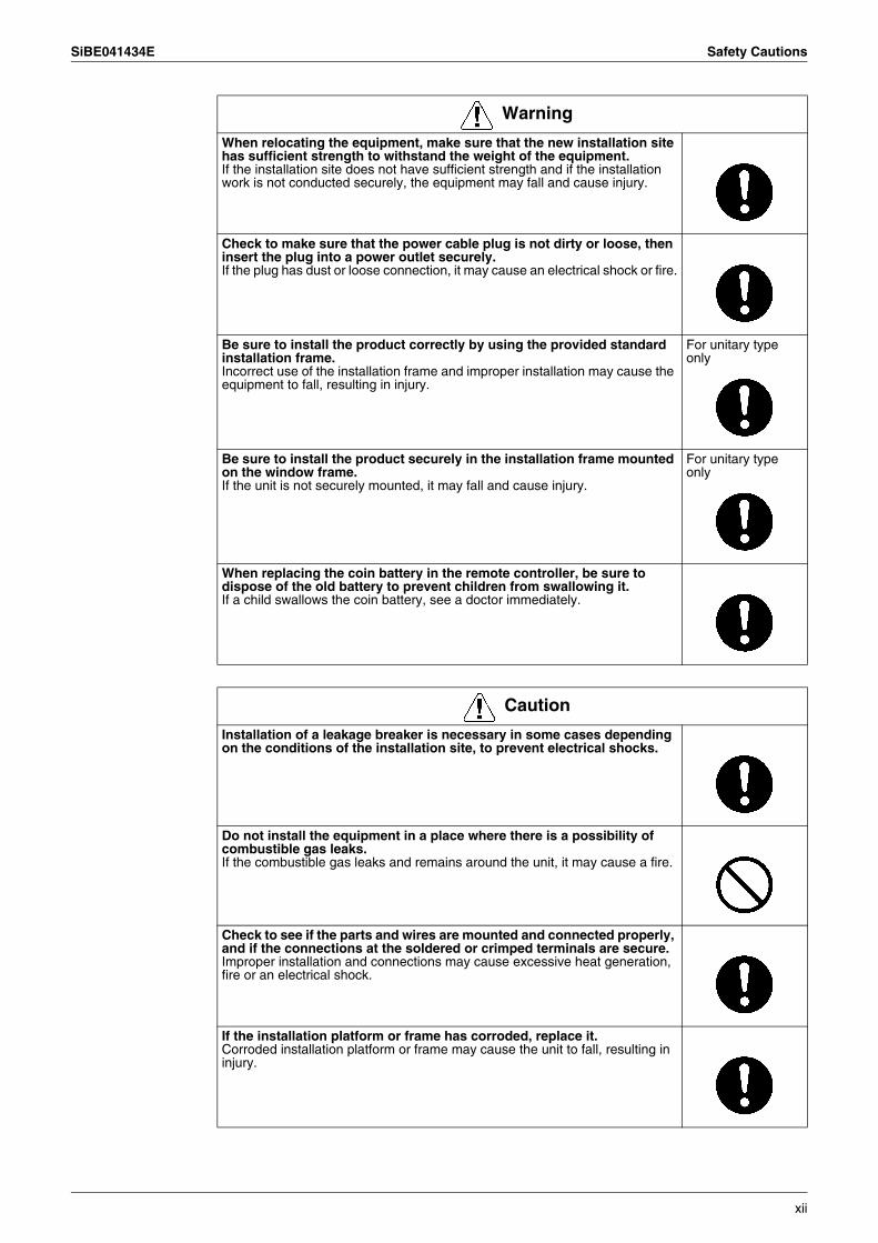
When relocating the equipment, make sure that the new installation site has sufficient strength to withstand the weight of the equipment.If the installation site does not have sufficient strength and if the installation work is not conducted securely, the equipment may fall and cause injury.
Check to make sure that the power cable plug is not dirty or loose, then insert the plug into a power outlet securely.If the plug has dust or loose connection, it may cause an electrical shock or fire.
Be sure to install the product correctly by using the provided standard installation frame.Incorrect use of the installation frame and improper installation may cause the equipment to fall, resulting in injury.
For unitary type only
Be sure to install the product securely in the installation frame mounted on the window frame.If the unit is not securely mounted, it may fall and cause injury.
For unitary type only
When replacing the coin battery in the remote controller, be sure to dispose of the old battery to prevent children from swallowing it.If a child swallows the coin battery, see a doctor immediately.
Warning
Caution
Installation of a leakage breaker is necessary in some cases depending on the conditions of the installation site, to prevent electrical shocks.
Do not install the equipment in a place where there is a possibility of combustible gas leaks.If the combustible gas leaks and remains around the unit, it may cause a fire.
Check to see if the parts and wires are mounted and connected properly, and if the connections at the soldered or crimped terminals are secure.Improper installation and connections may cause excessive heat generation, fire or an electrical shock.
If the installation platform or frame has corroded, replace it.Corroded installation platform or frame may cause the unit to fall, resulting in injury.
xii
Safety Cautions SiBE041434E
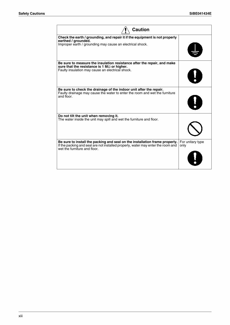
Check the earth / grounding, and repair it if the equipment is not properly earthed / grounded.Improper earth / grounding may cause an electrical shock.
Be sure to measure the insulation resistance after the repair, and make sure that the resistance is 1 MΩ or higher.Faulty insulation may cause an electrical shock.
Be sure to check the drainage of the indoor unit after the repair.Faulty drainage may cause the water to enter the room and wet the furniture and floor.
Do not tilt the unit when removing it.The water inside the unit may spill and wet the furniture and floor.
Be sure to install the packing and seal on the installation frame properly.If the packing and seal are not installed properly, water may enter the room and wet the furniture and floor.
For unitary type only
Caution
xiii
SiBE041434E Used Icons
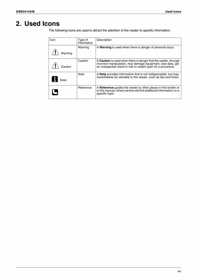
2. Used IconsThe following icons are used to attract the attention of the reader to specific information.
Icon Type of Information
Description
Warning
Warning A Warning is used when there is danger of personal injury.
Caution
Caution A Caution is used when there is danger that the reader, through incorrect manipulation, may damage equipment, lose data, get an unexpected result or has to restart (part of) a procedure.
Note:
Note A Note provides information that is not indispensable, but may nevertheless be valuable to the reader, such as tips and tricks.
Reference A Reference guides the reader to other places in this binder or in this manual, where he/she will find additional information on a specific topic.
xiv
SiBE041434E
1 List of Functions
Part 1List of Functions
1. Functions.................................................................................................2
SiBE041434E Functions
List of Functions 2
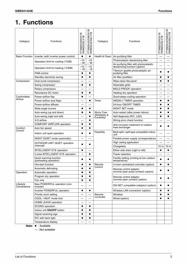
1. Functions
Category Functions
FT
XM
20/2
5K3V
1BR
XM
20/2
5LV
1B
FT
XM
35/4
2/50
K3V
1BR
XM
35/4
2/50
LV1B
Category Functions
FT
XM
20/2
5K3V
1BR
XM
20/2
5LV
1B
FT
XM
35/4
2/50
K3V
1BR
XM
35/4
2/50
LV1B
Basic Function Inverter (with inverter power control) Health & Clean Air-purifying filter — —
Operation limit for cooling (°CDB) –10~ 46
–10~ 46
Photocatalytic deodorizing filter — —
Air-purifying filter with photocatalytic deodorizing function (option) — —
Operation limit for heating (°CWB) –15~ 18
–15~ 18 Titanium apatite photocatalytic air-
purifying filterPAM control
Standby electricity saving Air filter (prefilter)
Compressor Oval scroll compressor — — Wipe-clean flat panel
Swing compressor Washable grille — —
Rotary compressor — — MOLD PROOF operation — —
Reluctance DC motor Heating dry operation — —
Comfortable Airflow
Power-airflow flap — Good-sleep cooling operation — —
Power-airflow dual flaps — Timer WEEKLY TIMER operation
Power-airflow diffuser — — 24-hour ON/OFF TIMER
Wide-angle louvers NIGHT SET mode
Auto-swing (up and down) Worry Free (Reliability & Durability)
Auto-restart (after power failure)
Auto-swing (right and left) — Self-diagnosis (R/C, LED)
3-D airflow — Wiring error check function — —
COMFORT AIRFLOW operation Anti-corrosion treatment of outdoor heat exchangerComfort
ControlAuto fan speed
Indoor unit quiet operation Flexibility Multi-split / split type compatible indoor unit — —
NIGHT QUIET mode (automatic) — — Flexible power supply correspondence — —
OUTDOOR UNIT QUIET operation (manual)
High ceiling application — —
Chargeless 10 m 10 m
INTELLIGENT EYE operation — Either side drain (right or left)
2-area INTELLIGENT EYE operation — Power selection — —
Quick warming function (preheating operation)
Facility setting (cooling at low outdoor temperature)
Hot-start function Remote Control
5-room centralized controller (option)
Automatic defrosting Remote control adaptor(normal open pulse contact) (option)Operation Automatic operation
Program dry operation Remote control adaptor (normal open contact) (option)Fan only
Lifestyle Convenience
New POWERFUL operation (non-inverter) — — DIII-NET compatible (adaptor) (option)
Inverter POWERFUL operation Wireless LAN connection (option)
Priority-room setting — — Remote Controller
Wireless
COOL / HEAT mode lock — — Wired (option)
HOME LEAVE operation — —
ECONO operation
Indoor unit ON/OFF button
Signal receiving sign
R/C with back light
Temperature display — —
Note: : Available— : Not available
SiBE041434E
3 Specifications
Part 2Specifications
1. Specifications ..........................................................................................4
SiBE041434E Specifications
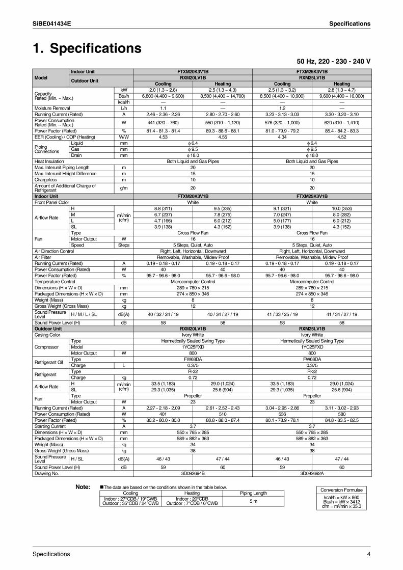
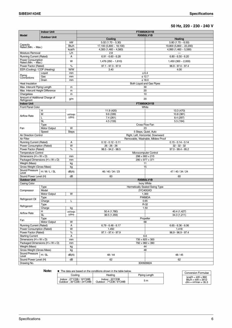
1. Specifications50 Hz, 220 - 230 - 240 V
Note: The data are based on the conditions shown in the table below.
ModelIndoor Unit FTXM20K3V1B FTXM25K3V1B
Outdoor UnitRXM20LV1B RXM25LV1B
Cooling Heating Cooling Heating
CapacityRated (Min. ~ Max.)
kW 2.0 (1.3 ~ 2.8) 2.5 (1.3 ~ 4.3) 2.5 (1.3 ~ 3.2) 2.8 (1.3 ~ 4.7)Btu/h 6,800 (4,400 ~ 9,600) 8,500 (4,400 ~ 14,700) 8,500 (4,400 ~ 10,900) 9,600 (4,400 ~ 16,000)kcal/h — — — —
Moisture Removal L/h 1.1 — 1.2 —Running Current (Rated) A 2.46 - 2.36 - 2.26 2.80 - 2.70 - 2.60 3.23 - 3.13 - 3.03 3.30 - 3.20 - 3.10Power ConsumptionRated (Min. ~ Max.) W 441 (320 ~ 760) 550 (310 ~ 1,120) 576 (320 ~ 1,000) 620 (310 ~ 1,410)
Power Factor (Rated) % 81.4 - 81.3 - 81.4 89.3 - 88.6 - 88.1 81.0 - 79.9 - 79.2 85.4 - 84.2 - 83.3EER (Cooling) / COP (Heating) W/W 4.53 4.55 4.34 4.52
Piping Connections
Liquid mm φ 6.4 φ 6.4Gas mm φ 9.5 φ 9.5Drain mm φ 18.0 φ 18.0
Heat Insulation Both Liquid and Gas Pipes Both Liquid and Gas PipesMax. Interunit Piping Length m 20 20Max. Interunit Height Difference m 15 15Chargeless m 10 10Amount of Additional Charge of Refrigerant g/m 20 20
Indoor Unit FTXM20K3V1B FTXM25K3V1BFront Panel Color White White
Airflow Rate
H
m³/min(cfm)
8.8 (311) 9.5 (335) 9.1 (321) 10.0 (353)M 6.7 (237) 7.8 (275) 7.0 (247) 8.0 (282)L 4.7 (166) 6.0 (212) 5.0 (177) 6.0 (212)SL 3.9 (138) 4.3 (152) 3.9 (138) 4.3 (152)
FanType Cross Flow Fan Cross Flow FanMotor Output W 16 16Speed Steps 5 Steps, Quiet, Auto 5 Steps, Quiet, Auto
Air Direction Control Right, Left, Horizontal, Downward Right, Left, Horizontal, DownwardAir Filter Removable, Washable, Mildew Proof Removable, Washable, Mildew ProofRunning Current (Rated) A 0.19 - 0.18 - 0.17 0.19 - 0.18 - 0.17 0.19 - 0.18 - 0.17 0.19 - 0.18 - 0.17Power Consumption (Rated) W 40 40 40 40Power Factor (Rated) % 95.7 - 96.6 - 98.0 95.7 - 96.6 - 98.0 95.7 - 96.6 - 98.0 95.7 - 96.6 - 98.0Temperature Control Microcomputer Control Microcomputer ControlDimensions (H × W × D) mm 289 × 780 × 215 289 × 780 × 215Packaged Dimensions (H × W × D) mm 274 × 850 × 346 274 × 850 × 346Weight (Mass) kg 8 8Gross Weight (Gross Mass) kg 12 12Sound Pressure Level H / M / L / SL dB(A) 40 / 32 / 24 / 19 40 / 34 / 27 / 19 41 / 33 / 25 / 19 41 / 34 / 27 / 19
Sound Power Level (H) dB 58 58 58 58Outdoor Unit RXM20LV1B RXM25LV1BCasing Color Ivory White Ivory White
CompressorType Hermetically Sealed Swing Type Hermetically Sealed Swing TypeModel 1YC25FXD 1YC25FXDMotor Output W 800 800
Refrigerant OilType FW68DA FW68DACharge L 0.375 0.375
RefrigerantType R-32 R-32Charge kg 0.72 0.72
Airflow RateH m³/min
(cfm)33.5 (1,183) 29.0 (1,024) 33.5 (1,183) 29.0 (1,024)
SL 29.3 (1,035) 25.6 (904) 29.3 (1,035) 25.6 (904)
FanType Propeller PropellerMotor Output W 23 23
Running Current (Rated) A 2.27 - 2.18 - 2.09 2.61 - 2.52 - 2.43 3.04 - 2.95 - 2.86 3.11 - 3.02 - 2.93Power Consumption (Rated) W 401 510 536 580Power Factor (Rated) % 80.2 - 80.0 - 80.0 88.8 - 88.0 - 87.4 80.1 - 78.9 - 78.1 84.8 - 83.5 - 82.5Starting Current A 3.7 3.7Dimensions (H × W × D) mm 550 × 765 × 285 550 × 765 × 285Packaged Dimensions (H × W × D) mm 589 × 882 × 363 589 × 882 × 363Weight (Mass) kg 34 34Gross Weight (Gross Mass) kg 38 38Sound Pressure Level H / SL dB(A) 46 / 43 47 / 44 46 / 43 47 / 44
Sound Power Level (H) dB 59 60 59 60Drawing No. 3D092694B 3D092692A
Conversion Formulae
kcal/h = kW × 860Btu/h = kW × 3412
cfm = m³/min × 35.3
Cooling Heating Piping LengthIndoor ; 27°CDB / 19°CWB
Outdoor ; 35°CDB / 24°CWBIndoor ; 20°CDB
Outdoor ; 7°CDB / 6°CWB 5 m
Specifications 4
Specifications SiBE041434E
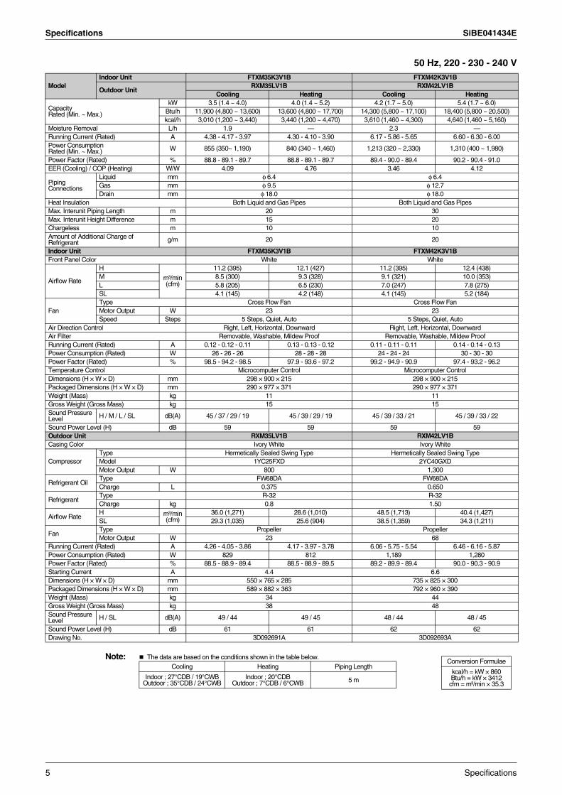
50 Hz, 220 - 230 - 240 V
Note: The data are based on the conditions shown in the table below.
ModelIndoor Unit FTXM35K3V1B FTXM42K3V1B
Outdoor UnitRXM35LV1B RXM42LV1B
Cooling Heating Cooling Heating
CapacityRated (Min. ~ Max.)
kW 3.5 (1.4 ~ 4.0) 4.0 (1.4 ~ 5.2) 4.2 (1.7 ~ 5.0) 5.4 (1.7 ~ 6.0)Btu/h 11,900 (4,800 ~ 13,600) 13,600 (4,800 ~ 17,700) 14,300 (5,800 ~ 17,100) 18,400 (5,800 ~ 20,500)kcal/h 3,010 (1,200 ~ 3,440) 3,440 (1,200 ~ 4,470) 3,610 (1,460 ~ 4,300) 4,640 (1,460 ~ 5,160)
Moisture Removal L/h 1.9 — 2.3 —Running Current (Rated) A 4.38 - 4.17 - 3.97 4.30 - 4.10 - 3.90 6.17 - 5.86 - 5.65 6.60 - 6.30 - 6.00Power ConsumptionRated (Min. ~ Max.) W 855 (350~ 1,190) 840 (340 ~ 1,460) 1,213 (320 ~ 2,330) 1,310 (400 ~ 1,980)
Power Factor (Rated) % 88.8 - 89.1 - 89.7 88.8 - 89.1 - 89.7 89.4 - 90.0 - 89.4 90.2 - 90.4 - 91.0EER (Cooling) / COP (Heating) W/W 4.09 4.76 3.46 4.12
Piping Connections
Liquid mm φ 6.4 φ 6.4Gas mm φ 9.5 φ 12.7Drain mm φ 18.0 φ 18.0
Heat Insulation Both Liquid and Gas Pipes Both Liquid and Gas PipesMax. Interunit Piping Length m 20 30Max. Interunit Height Difference m 15 20Chargeless m 10 10Amount of Additional Charge of Refrigerant g/m 20 20
Indoor Unit FTXM35K3V1B FTXM42K3V1BFront Panel Color White White
Airflow Rate
H
m³/min(cfm)
11.2 (395) 12.1 (427) 11.2 (395) 12.4 (438)M 8.5 (300) 9.3 (328) 9.1 (321) 10.0 (353)L 5.8 (205) 6.5 (230) 7.0 (247) 7.8 (275)SL 4.1 (145) 4.2 (148) 4.1 (145) 5.2 (184)
FanType Cross Flow Fan Cross Flow FanMotor Output W 23 23Speed Steps 5 Steps, Quiet, Auto 5 Steps, Quiet, Auto
Air Direction Control Right, Left, Horizontal, Downward Right, Left, Horizontal, DownwardAir Filter Removable, Washable, Mildew Proof Removable, Washable, Mildew ProofRunning Current (Rated) A 0.12 - 0.12 - 0.11 0.13 - 0.13 - 0.12 0.11 - 0.11 - 0.11 0.14 - 0.14 - 0.13Power Consumption (Rated) W 26 - 26 - 26 28 - 28 - 28 24 - 24 - 24 30 - 30 - 30Power Factor (Rated) % 98.5 - 94.2 - 98.5 97.9 - 93.6 - 97.2 99.2 - 94.9 - 90.9 97.4 - 93.2 - 96.2Temperature Control Microcomputer Control Microcomputer ControlDimensions (H × W × D) mm 298 × 900 × 215 298 × 900 × 215Packaged Dimensions (H × W × D) mm 290 × 977 × 371 290 × 977 × 371Weight (Mass) kg 11 11Gross Weight (Gross Mass) kg 15 15Sound Pressure Level H / M / L / SL dB(A) 45 / 37 / 29 / 19 45 / 39 / 29 / 19 45 / 39 / 33 / 21 45 / 39 / 33 / 22
Sound Power Level (H) dB 59 59 59 59Outdoor Unit RXM35LV1B RXM42LV1BCasing Color Ivory White Ivory White
CompressorType Hermetically Sealed Swing Type Hermetically Sealed Swing TypeModel 1YC25FXD 2YC40GXDMotor Output W 800 1,300
Refrigerant OilType FW68DA FW68DACharge L 0.375 0.650
RefrigerantType R-32 R-32Charge kg 0.8 1.50
Airflow RateH m³/min
(cfm)36.0 (1,271) 28.6 (1,010) 48.5 (1,713) 40.4 (1,427)
SL 29.3 (1,035) 25.6 (904) 38.5 (1,359) 34.3 (1,211)
FanType Propeller PropellerMotor Output W 23 68
Running Current (Rated) A 4.26 - 4.05 - 3.86 4.17 - 3.97 - 3.78 6.06 - 5.75 - 5.54 6.46 - 6.16 - 5.87Power Consumption (Rated) W 829 812 1,189 1,280Power Factor (Rated) % 88.5 - 88.9 - 89.4 88.5 - 88.9 - 89.5 89.2 - 89.9 - 89.4 90.0 - 90.3 - 90.9Starting Current A 4.4 6.6Dimensions (H × W × D) mm 550 × 765 × 285 735 × 825 × 300Packaged Dimensions (H × W × D) mm 589 × 882 × 363 792 × 960 × 390Weight (Mass) kg 34 44Gross Weight (Gross Mass) kg 38 48Sound Pressure Level H / SL dB(A) 49 / 44 49 / 45 48 / 44 48 / 45
Sound Power Level (H) dB 61 61 62 62Drawing No. 3D092691A 3D092693A
Conversion Formulae
kcal/h = kW × 860Btu/h = kW × 3412
cfm = m³/min × 35.3
Cooling Heating Piping Length
Indoor ; 27°CDB / 19°CWB Outdoor ; 35°CDB / 24°CWB
Indoor ; 20°CDBOutdoor ; 7°CDB / 6°CWB 5 m
5 Specifications
SiBE041434E Specifications
50 Hz, 220 - 230 - 240 V
Note: The data are based on the conditions shown in the table below.
ModelIndoor Unit FTXM50K3V1B
Outdoor UnitRXM50LV1B
Cooling Heating
CapacityRated (Min. ~ Max.)
kW 5.02 (1.70 ~ 5.30) 5.80 (1.70 ~ 6.50)Btu/h 17,100 (5,800 ~ 18,100) 19,800 (5,800 ~ 22,200)kcal/h 4,300 (1,460 ~ 4,560) 4,990 (1,460 ~ 5,590)
Moisture Removal L/h 2.8 —Running Current (Rated) A 6.91 - 6.60 - 6.28 6.80 - 6.50 - 6.20Power ConsumptionRated (Min. ~ Max.) W 1,476 (350 ~ 1,810) 1,450 (300 ~ 2,000)
Power Factor (Rated) % 97.1 - 97.3 - 97.9 96.9 - 97.0 - 97.4EER (Cooling) / COP (Heating) W/W 3.40 4.00
Piping Connections
Liquid mm φ 6.4Gas mm φ 12.7Drain mm φ 18.0
Heat Insulation Both Liquid and Gas PipesMax. Interunit Piping Length m 30Max. Interunit Height Difference m 20Chargeless m 10Amount of Additional Charge of Refrigerant g/m 20
Indoor Unit FTXM50K3V1BFront Panel Color White
Airflow Rate
H
m³/min(cfm)
11.9 (420) 13.3 (470)M 9.6 (339) 10.8 (381)L 7.4 (261) 8.4 (297)SL 4.5 (159) 5.5 (194)
FanType Cross Flow FanMotor Output W 23Speed Steps 5 Steps, Quiet, Auto
Air Direction Control Right, Left, Horizontal, DownwardAir Filter Removable, Washable, Mildew ProofRunning Current (Rated) A 0.12 - 0.12 - 0.11 0.15 - 0.14 - 0.14Power Consumption (Rated) W 26 - 26 - 26 32 - 32 - 32Power Factor (Rated) % 98.5 - 94.2 - 98.5 97.0 - 99.4 - 95.2Temperature Control Microcomputer ControlDimensions (H × W × D) mm 298 × 900 × 215Packaged Dimensions (H × W × D) mm 290 × 977 × 371Weight (Mass) kg 11Gross Weight (Gross Mass) kg 15Sound Pressure Level H / M / L / SL dB(A) 46 / 40 / 34 / 23 47 / 40 / 34 / 24
Sound Power Level (H) dB 60 60Outdoor Unit RXM50LV1BCasing Color Ivory White
CompressorType Hermetically Sealed Swing TypeModel 2YC40GXDMotor Output W 1,300
Refrigerant OilType FW68DACharge L 0.65
RefrigerantType R-32Charge kg 1.50
Airflow RateH m³/min
(cfm)50.4 (1,780) 40.4 (1,427)
SL 38.5 (1,359) 34.3 (1,211)
FanType PropellerMotor Output W 68
Running Current (Rated) A 6.79 - 6.48 - 6.17 6.65 - 6.36 - 6.06Power Consumption (Rated) W 1,450 1,418Power Factor (Rated) % 97.1 - 97.4 - 97.9 96.9 - 96.9 - 97.4Starting Current A 6.6Dimensions (H × W × D) mm 735 × 825 × 300Packaged Dimensions (H × W × D) mm 792 × 960 × 390Weight (Mass) kg 44Gross Weight (Gross Mass) kg 48Sound Pressure Level H / SL dB(A) 48 / 44 48 / 45
Sound Power Level (H) dB 62 62Drawing No. 3D092682A
Conversion Formulae
kcal/h = kW × 860Btu/h = kW × 3412
cfm = m³/min × 35.3
Cooling Heating Piping Length
Indoor ; 27°CDB / 19°CWB Outdoor ; 35°CDB / 24°CWB
Indoor ; 20°CDBOutdoor ; 7°CDB / 6°CWB 5 m
Specifications 6
SiBE041434E
7 Printed Circuit Board Connector Wiring Diagram
Part 3Printed Circuit Board
Connector Wiring Diagram
1. Indoor Unit...............................................................................................81.1 20/25 Class ..............................................................................................81.2 35/42/50 Class .......................................................................................10
2. Outdoor Unit..........................................................................................122.1 20/25/35 Class .......................................................................................122.2 42/50 Class ............................................................................................14
SiBE041434E Indoor Unit
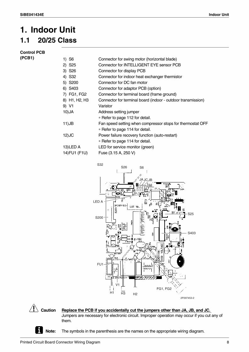
1. Indoor Unit1.1 20/25 Class
Control PCB (PCB1)
Caution Replace the PCB if you accidentally cut the jumpers other than JA, JB, and JC. Jumpers are necessary for electronic circuit. Improper operation may occur if you cut any of them.
Note: The symbols in the parenthesis are the names on the appropriate wiring diagram.
1) S6 Connector for swing motor (horizontal blade)2) S25 Connector for INTELLIGENT EYE sensor PCB3) S26 Connector for display PCB4) S32 Connector for indoor heat exchanger thermistor5) S200 Connector for DC fan motor6) S403 Connector for adaptor PCB (option)7) FG1, FG2 Connector for terminal board (frame ground)8) H1, H2, H3 Connector for terminal board (indoor - outdoor transmission)9) V1 Varistor10)JA Address setting jumper
∗ Refer to page 112 for detail.11)JB Fan speed setting when compressor stops for thermostat OFF
∗ Refer to page 114 for detail.12)JC Power failure recovery function (auto-restart)
∗ Refer to page 114 for detail.13)LED A LED for service monitor (green)14)FU1 (F1U) Fuse (3.15 A, 250 V)
FU1
FG1, FG2
LED A
S200
2P297453-2
S32S26 S6
JA JCJB
S25
S403
H2H3H1
V1
Printed Circuit Board Connector Wiring Diagram 8
Indoor Unit SiBE041434E
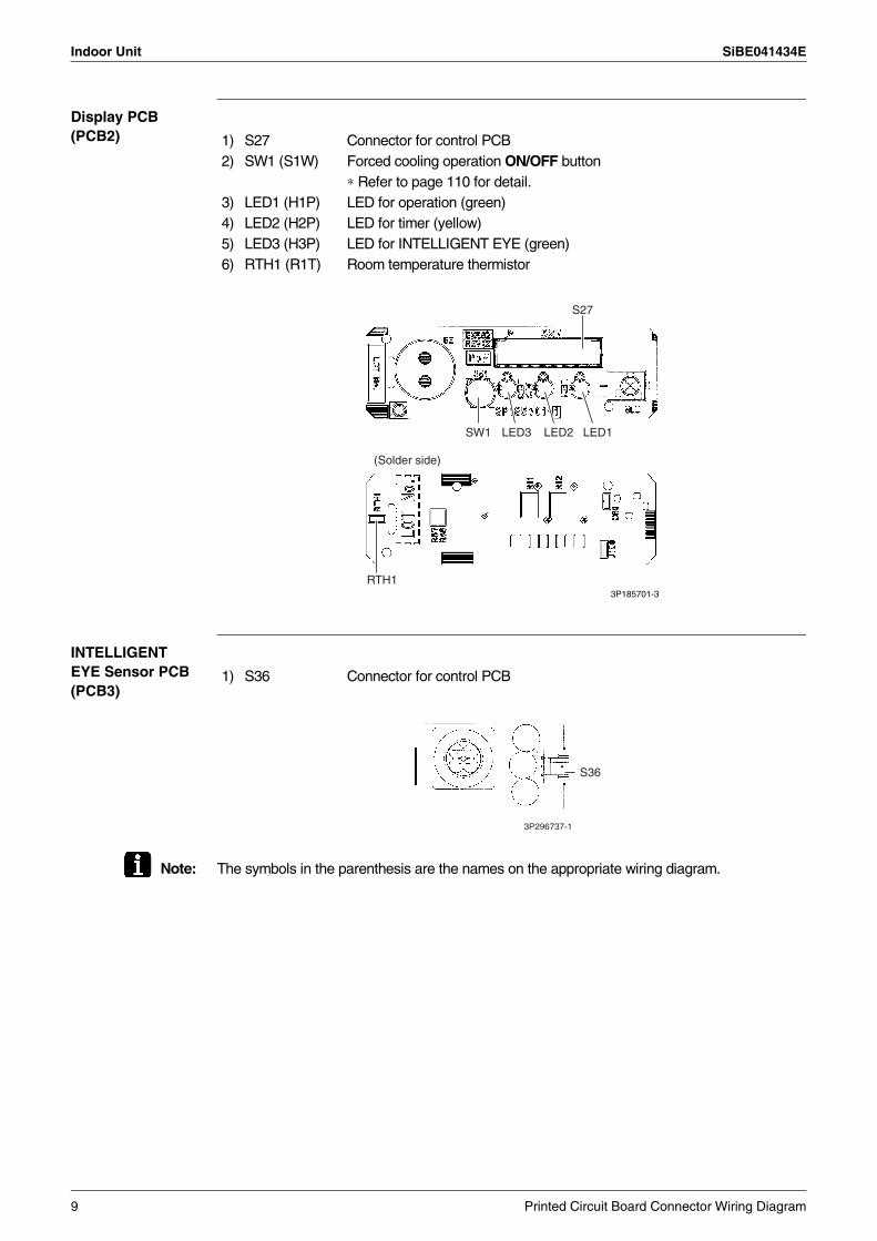
Display PCB (PCB2)
INTELLIGENT EYE Sensor PCB (PCB3)
Note: The symbols in the parenthesis are the names on the appropriate wiring diagram.
1) S27 Connector for control PCB2) SW1 (S1W) Forced cooling operation ON/OFF button
∗ Refer to page 110 for detail.3) LED1 (H1P) LED for operation (green)4) LED2 (H2P) LED for timer (yellow)5) LED3 (H3P) LED for INTELLIGENT EYE (green)6) RTH1 (R1T) Room temperature thermistor
S27
SW1
(Solder side)
LED2LED3 LED1
RTH13P185701-3
1) S36 Connector for control PCB
S36
3P296737-1
9 Printed Circuit Board Connector Wiring Diagram
SiBE041434E Indoor Unit
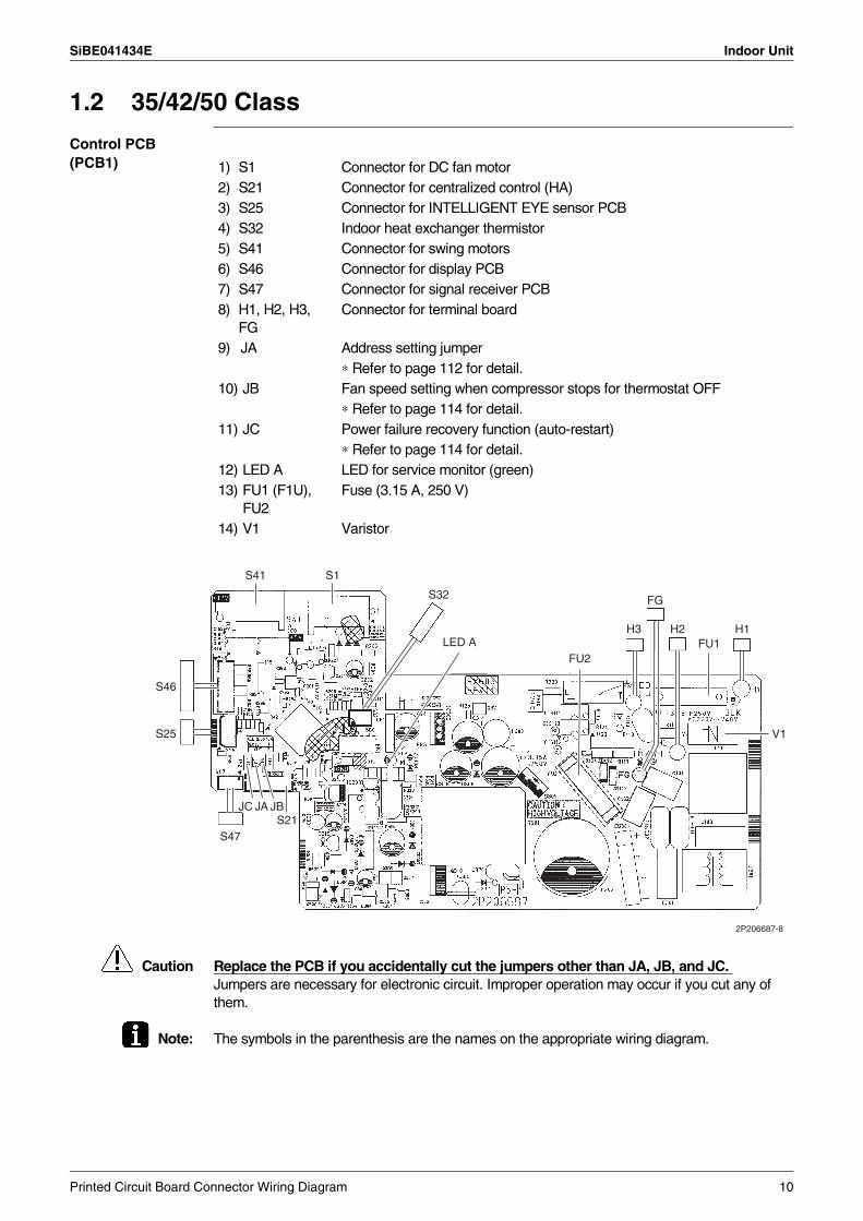
1.2 35/42/50 Class
Control PCB (PCB1)
Caution Replace the PCB if you accidentally cut the jumpers other than JA, JB, and JC. Jumpers are necessary for electronic circuit. Improper operation may occur if you cut any of them.
Note: The symbols in the parenthesis are the names on the appropriate wiring diagram.
1) S1 Connector for DC fan motor2) S21 Connector for centralized control (HA)3) S25 Connector for INTELLIGENT EYE sensor PCB4) S32 Indoor heat exchanger thermistor5) S41 Connector for swing motors6) S46 Connector for display PCB7) S47 Connector for signal receiver PCB8) H1, H2, H3,
FGConnector for terminal board
9) JA Address setting jumper∗ Refer to page 112 for detail.
10) JB Fan speed setting when compressor stops for thermostat OFF ∗ Refer to page 114 for detail.11) JC Power failure recovery function (auto-restart) ∗ Refer to page 114 for detail.12) LED A LED for service monitor (green)13) FU1 (F1U),
FU2Fuse (3.15 A, 250 V)
14) V1 Varistor
V1
FU1
S1S41
S21S47
JBJAJC
S46
S25
LED AFU2
S32 FG
H1H2H3
2P206687-8
Printed Circuit Board Connector Wiring Diagram 10
Indoor Unit SiBE041434E
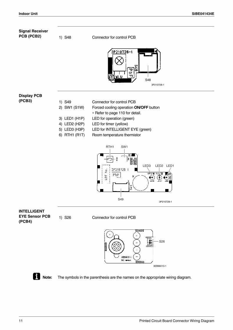
Signal Receiver PCB (PCB2)
Display PCB (PCB3)
INTELLIGENT EYE Sensor PCB (PCB4)
Note: The symbols in the parenthesis are the names on the appropriate wiring diagram.
1) S48 Connector for control PCB
3P210728-1
S48
1) S49 Connector for control PCB2) SW1 (S1W) Forced cooling operation ON/OFF button
∗ Refer to page 110 for detail.3) LED1 (H1P) LED for operation (green)4) LED2 (H2P) LED for timer (yellow)5) LED3 (H3P) LED for INTELLIGENT EYE (green)6) RTH1 (R1T) Room temperature thermistor
3P210728-1
RTH1 SW1
LED3 LED2 LED1
S49
1) S26 Connector for control PCB
3EB86013-1
S26
11 Printed Circuit Board Connector Wiring Diagram
SiBE041434E Outdoor Unit
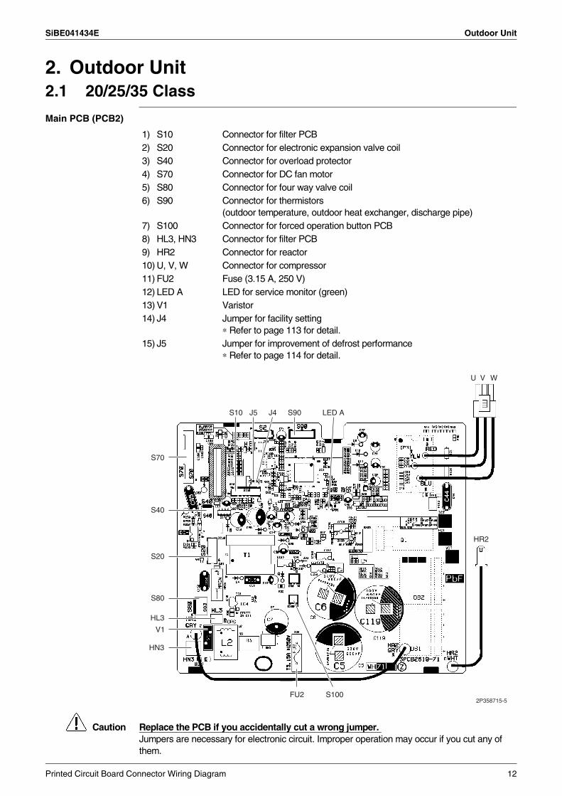
2. Outdoor Unit2.1 20/25/35 Class
Main PCB (PCB2)
Caution Replace the PCB if you accidentally cut a wrong jumper. Jumpers are necessary for electronic circuit. Improper operation may occur if you cut any of them.
1) S10 Connector for filter PCB2) S20 Connector for electronic expansion valve coil3) S40 Connector for overload protector4) S70 Connector for DC fan motor5) S80 Connector for four way valve coil6) S90 Connector for thermistors
(outdoor temperature, outdoor heat exchanger, discharge pipe)7) S100 Connector for forced operation button PCB8) HL3, HN3 Connector for filter PCB9) HR2 Connector for reactor10) U, V, W Connector for compressor11) FU2 Fuse (3.15 A, 250 V)12) LED A LED for service monitor (green)13) V1 Varistor14) J4 Jumper for facility setting
∗ Refer to page 113 for detail.15) J5 Jumper for improvement of defrost performance
∗ Refer to page 114 for detail.
S10 J5 J4 S90
FU2 S100
S70
S40
S20
S80
HL3
HN3
V1
LED A
U V W
HR2
2P358715-5
Printed Circuit Board Connector Wiring Diagram 12
Outdoor Unit SiBE041434E
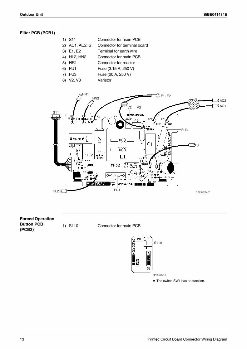
Filter PCB (PCB1)
Forced Operation Button PCB (PCB3)
The switch SW1 has no function.
1) S11 Connector for main PCB2) AC1, AC2, S Connector for terminal board3) E1, E2 Terminal for earth wire4) HL2, HN2 Connector for main PCB5) HR1 Connector for reactor6) FU1 Fuse (3.15 A, 250 V)7) FU3 Fuse (20 A, 250 V)8) V2, V3 Varistor
HR1
HL2 3P254234-7FU1
HN2
S
FU3
AC2E1, E2
AC1
S11
V3V2
1) S110 Connector for main PCB
S110
3P255755-2
13 Printed Circuit Board Connector Wiring Diagram
SiBE041434E Outdoor Unit
2.2 42/50 Class
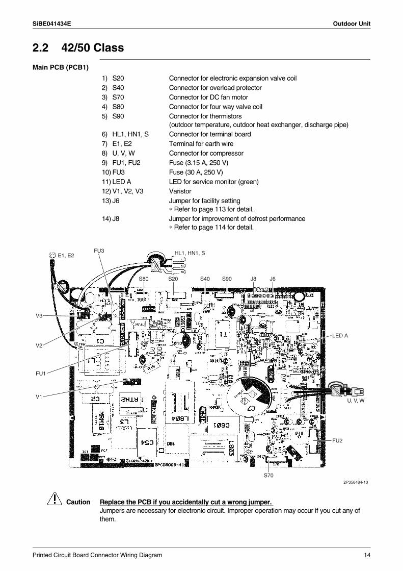
Main PCB (PCB1)
Caution Replace the PCB if you accidentally cut a wrong jumper. Jumpers are necessary for electronic circuit. Improper operation may occur if you cut any of them.
1) S20 Connector for electronic expansion valve coil2) S40 Connector for overload protector3) S70 Connector for DC fan motor4) S80 Connector for four way valve coil5) S90 Connector for thermistors
(outdoor temperature, outdoor heat exchanger, discharge pipe)6) HL1, HN1, S Connector for terminal board7) E1, E2 Terminal for earth wire8) U, V, W Connector for compressor9) FU1, FU2 Fuse (3.15 A, 250 V)10) FU3 Fuse (30 A, 250 V)11) LED A LED for service monitor (green)12) V1, V2, V3 Varistor13) J6 Jumper for facility setting
∗ Refer to page 113 for detail.14) J8 Jumper for improvement of defrost performance
∗ Refer to page 114 for detail.
U, V, W
FU3
FU1
FU2
V3
V2
V1
S20S80 S40 S90 J8
S702P356484-10
E1, E2 HL1, HN1, S
LED A
J6
Printed Circuit Board Connector Wiring Diagram 14
SiBE041434E
15 Function and Control
Part 4Function and Control
1. Main Functions......................................................................................161.1 Temperature Control ..............................................................................161.2 Frequency Principle................................................................................161.3 Airflow Direction Control.........................................................................181.4 Fan Speed Control for Indoor Unit .........................................................201.5 Program Dry Operation ..........................................................................211.6 Automatic Operation...............................................................................221.7 Thermostat Control.................................................................................231.8 NIGHT SET Mode ..................................................................................241.9 ECONO Operation .................................................................................241.10 INTELLIGENT EYE Operation (20/25 Class).........................................251.11 2-Area INTELLIGENT EYE Operation (35/42/50 Class) ........................261.12 Inverter POWERFUL Operation .............................................................281.13 Clock Setting ..........................................................................................291.14 WEEKLY TIMER Operation ...................................................................301.15 Other Functions......................................................................................36
2. Function of Thermistor ..........................................................................373. Control Specification .............................................................................38
3.1 Mode Hierarchy ......................................................................................383.2 Frequency Control..................................................................................383.3 Controls at Mode Changing / Start-up....................................................403.4 Discharge Pipe Temperature Control.....................................................423.5 Input Current Control..............................................................................433.6 Freeze-up Protection Control .................................................................443.7 Heating Peak-cut Control .......................................................................443.8 Outdoor Fan Control...............................................................................453.9 Liquid Compression Protection Function................................................453.10 Defrost Control .......................................................................................463.11 Electronic Expansion Valve Control .......................................................473.12 Malfunctions ...........................................................................................50
SiBE041434E Main Functions
1. Main Functions1.1 Temperature Control
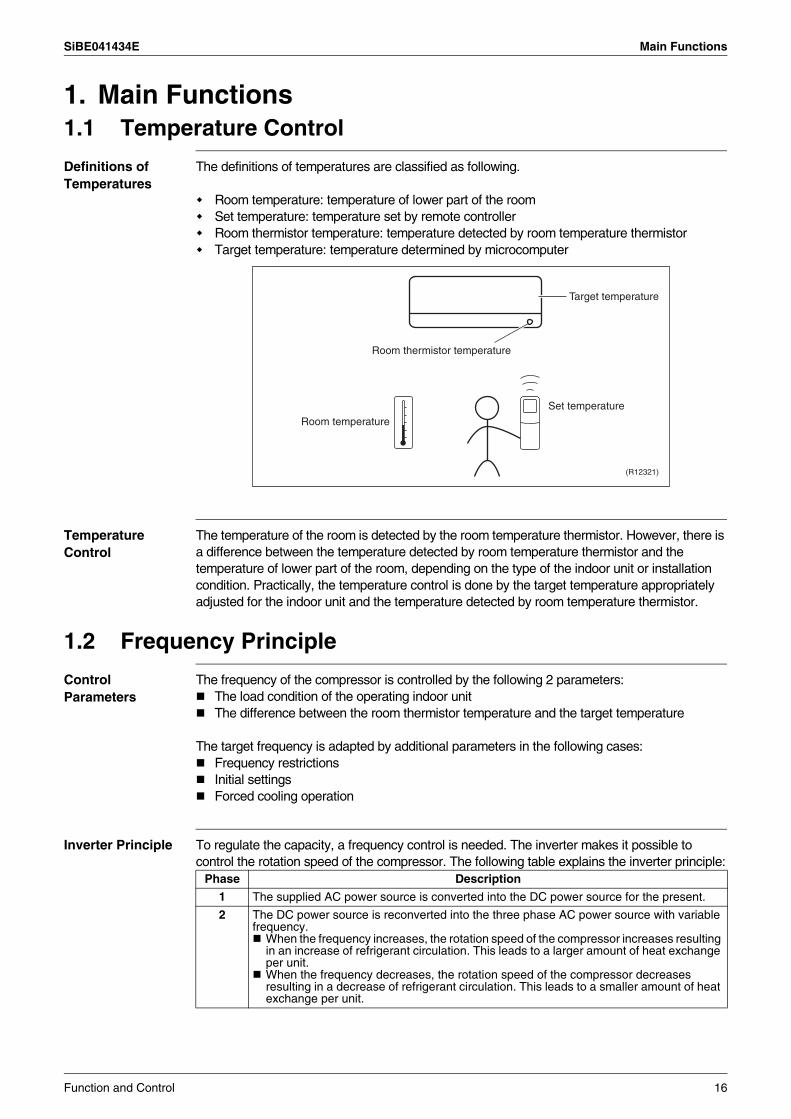
Definitions of Temperatures
The definitions of temperatures are classified as following.
Room temperature: temperature of lower part of the roomSet temperature: temperature set by remote controllerRoom thermistor temperature: temperature detected by room temperature thermistorTarget temperature: temperature determined by microcomputer
Temperature Control
The temperature of the room is detected by the room temperature thermistor. However, there is a difference between the temperature detected by room temperature thermistor and the temperature of lower part of the room, depending on the type of the indoor unit or installation condition. Practically, the temperature control is done by the target temperature appropriately adjusted for the indoor unit and the temperature detected by room temperature thermistor.
1.2 Frequency Principle
Control Parameters
The frequency of the compressor is controlled by the following 2 parameters:The load condition of the operating indoor unitThe difference between the room thermistor temperature and the target temperature
The target frequency is adapted by additional parameters in the following cases:Frequency restrictionsInitial settingsForced cooling operation
Inverter Principle To regulate the capacity, a frequency control is needed. The inverter makes it possible to control the rotation speed of the compressor. The following table explains the inverter principle:
Target temperature
Set temperature
Room temperature
Room thermistor temperature
(R12321)
Phase Description
1 The supplied AC power source is converted into the DC power source for the present.
2 The DC power source is reconverted into the three phase AC power source with variable frequency.
When the frequency increases, the rotation speed of the compressor increases resulting in an increase of refrigerant circulation. This leads to a larger amount of heat exchange per unit.When the frequency decreases, the rotation speed of the compressor decreases resulting in a decrease of refrigerant circulation. This leads to a smaller amount of heat exchange per unit.
Function and Control 16
Main Functions SiBE041434E
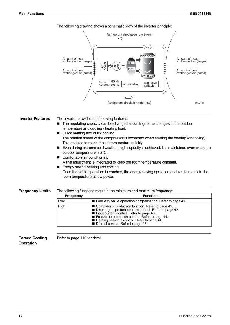
The following drawing shows a schematic view of the inverter principle:
Inverter Features The inverter provides the following features:The regulating capacity can be changed according to the changes in the outdoor temperature and cooling / heating load.Quick heating and quick coolingThe rotation speed of the compressor is increased when starting the heating (or cooling). This enables to reach the set temperature quickly.Even during extreme cold weather, high capacity is achieved. It is maintained even when the outdoor temperature is 2°C.Comfortable air conditioning A fine adjustment is integrated to keep the room temperature constant.Energy saving heating and coolingOnce the set temperature is reached, the energy saving operation enables to maintain the room temperature at low power.
Frequency Limits The following functions regulate the minimum and maximum frequency:
Forced Cooling Operation
Refer to page 110 for detail.
Refrigerant circulation rate (high)
high f
low f
freq=variable
Refrigerant circulation rate (low)
high speed
low speed
(R2812)
Amount of heat exchanged air (large)
freq= constant
50 Hz 60 Hz
capacity= variable
Amount of heat exchanged air (small)
AC
po
wer
DC
po
wer
Amount of heat exchanged air (large)
Amount of heat exchanged air (small)
Frequency Functions
Low Four way valve operation compensation. Refer to page 41.
High Compressor protection function. Refer to page 41.Discharge pipe temperature control. Refer to page 42.Input current control. Refer to page 43.Freeze-up protection control. Refer to page 44.Heating peak-cut control. Refer to page 44.Defrost control. Refer to page 46.
17 Function and Control
SiBE041434E Main Functions
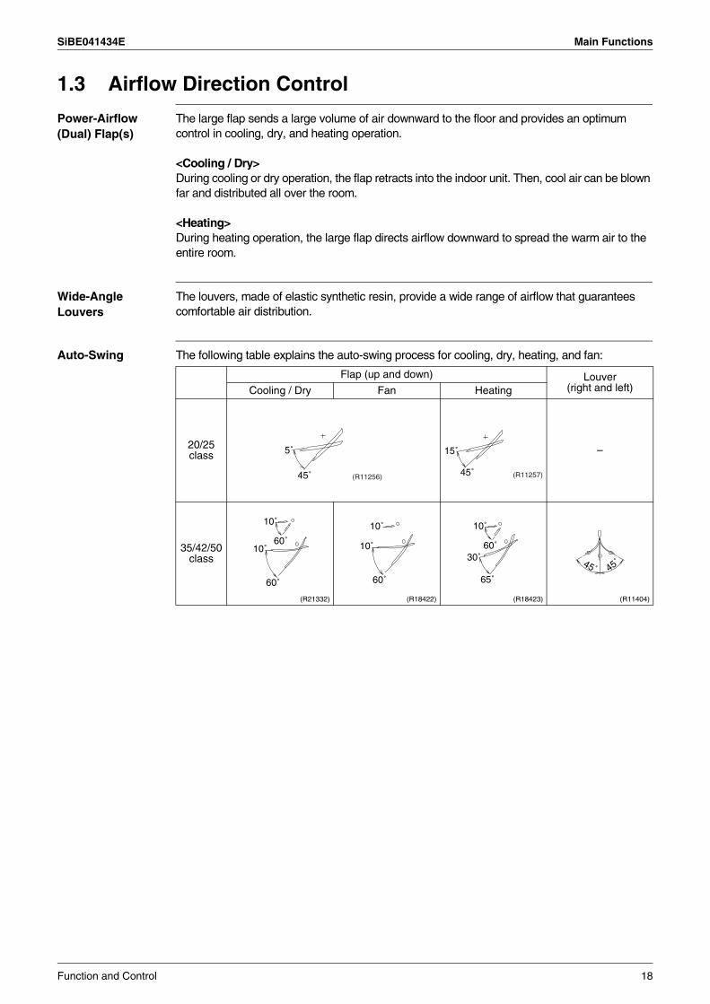
1.3 Airflow Direction Control
Power-Airflow (Dual) Flap(s)
The large flap sends a large volume of air downward to the floor and provides an optimum control in cooling, dry, and heating operation.
<Cooling / Dry>During cooling or dry operation, the flap retracts into the indoor unit. Then, cool air can be blown far and distributed all over the room.
<Heating>During heating operation, the large flap directs airflow downward to spread the warm air to the entire room.
Wide-Angle Louvers
The louvers, made of elastic synthetic resin, provide a wide range of airflow that guarantees comfortable air distribution.
Auto-Swing The following table explains the auto-swing process for cooling, dry, heating, and fan:
Flap (up and down) Louver (right and left)Cooling / Dry Fan Heating
20/25 class –
35/42/50 class
(R21332) (R18422) (R18423) (R11404)
(R11256)
5˚
45˚ (R11257)
15˚
45˚
10˚
60˚
10˚
60˚
10˚
10˚
60˚
10˚
60˚30˚
65˚45˚45˚
Function and Control 18
Main Functions SiBE041434E
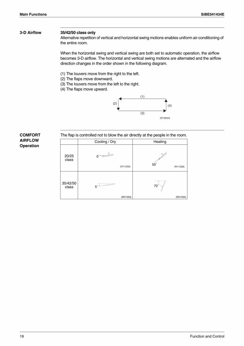
3-D Airflow 35/42/50 class onlyAlternative repetition of vertical and horizontal swing motions enables uniform air-conditioning of the entire room.
When the horizontal swing and vertical swing are both set to automatic operation, the airflow becomes 3-D airflow. The horizontal and vertical swing motions are alternated and the airflow direction changes in the order shown in the following diagram.
(1) The louvers move from the right to the left. (2) The flaps move downward.(3) The louvers move from the left to the right. (4) The flaps move upward.
COMFORT AIRFLOW Operation
The flap is controlled not to blow the air directly at the people in the room.
(R19554)
(2)(4)
(3)
(1)
Cooling / Dry Heating
20/25 class
35/42/50 class
(R21333) (R21334)
(R11259)
0˚
(R11258)50˚
5˚ 70˚
19 Function and Control
SiBE041434E Main Functions
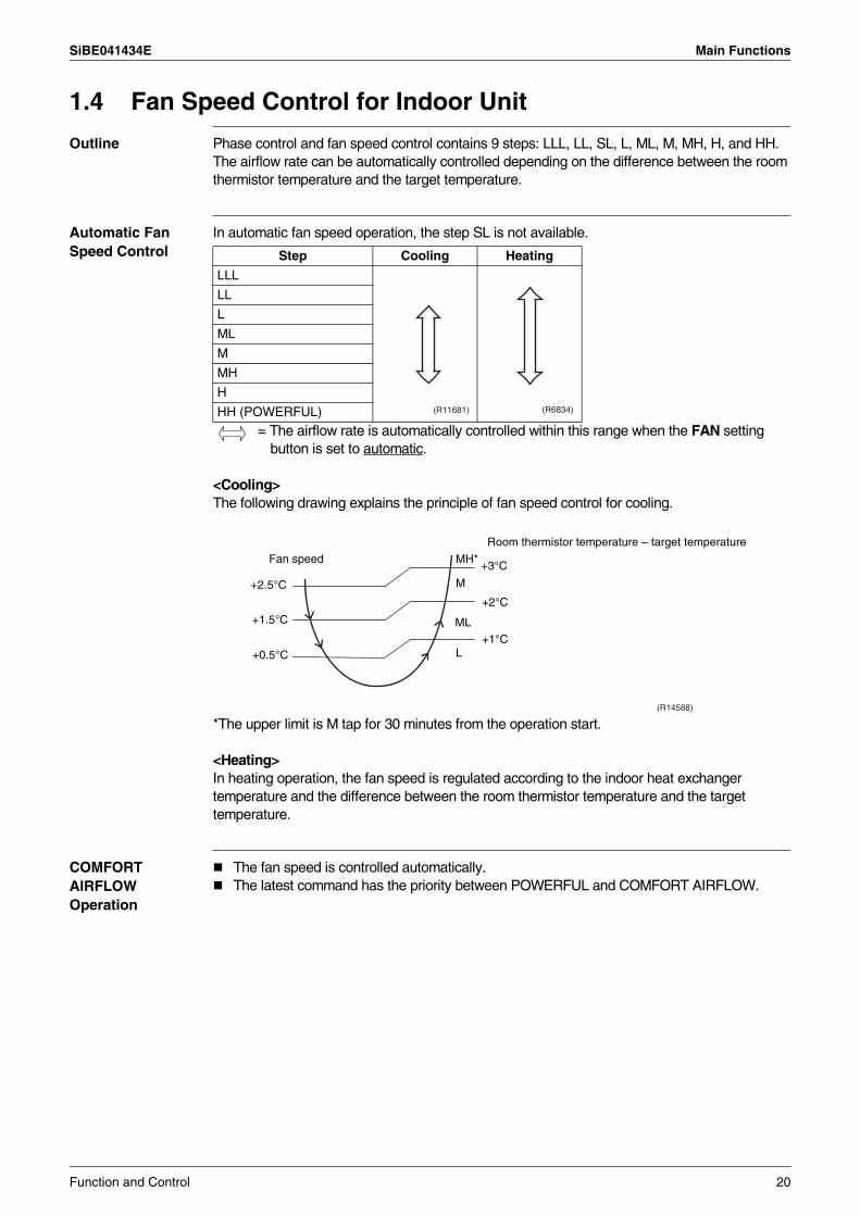
1.4 Fan Speed Control for Indoor Unit
Outline Phase control and fan speed control contains 9 steps: LLL, LL, SL, L, ML, M, MH, H, and HH.The airflow rate can be automatically controlled depending on the difference between the room thermistor temperature and the target temperature.
Automatic Fan Speed Control
In automatic fan speed operation, the step SL is not available.
= The airflow rate is automatically controlled within this range when the FAN setting button is set to automatic.
<Cooling>The following drawing explains the principle of fan speed control for cooling.
*The upper limit is M tap for 30 minutes from the operation start.
<Heating>In heating operation, the fan speed is regulated according to the indoor heat exchanger temperature and the difference between the room thermistor temperature and the target temperature.
COMFORT AIRFLOW Operation
The fan speed is controlled automatically.The latest command has the priority between POWERFUL and COMFORT AIRFLOW.
Step Cooling Heating
LLL
LL
L
ML
M
MH
H
HH (POWERFUL) (R11681) (R6834)
(R14588)
Fan speed
+2.5°C
+1.5°C
+0.5°C
MH*
M
ML
L
+3°C
+2°C
+1°C
Room thermistor temperature – target temperature
Function and Control 20
Main Functions SiBE041434E
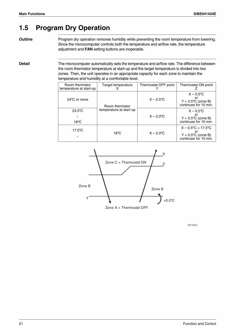
1.5 Program Dry Operation
Outline Program dry operation removes humidity while preventing the room temperature from lowering.Since the microcomputer controls both the temperature and airflow rate, the temperature adjustment and FAN setting buttons are inoperable.
Detail The microcomputer automatically sets the temperature and airflow rate. The difference between the room thermistor temperature at start-up and the target temperature is divided into two zones. Then, the unit operates in an appropriate capacity for each zone to maintain the temperature and humidity at a comfortable level.
Room thermistor temperature at start-up
Target temperatureX
Thermostat OFF pointY
Thermostat ON pointZ
24ºC or more
Room thermistor temperature at start-up
X – 2.5ºC
X – 0.5ºCor
Y + 0.5ºC (zone B) continues for 10 min.
23.5ºC
X – 2.0ºC
X – 0.5ºCor
Y + 0.5ºC (zone B) continues for 10 min.
~
18ºC
18ºC X – 2.0ºC
X – 0.5ºC = 17.5ºCor
Y + 0.5ºC (zone B) continues for 10 min.
17.5ºC
~
Zone A = Thermostat OFF
Y+0.5ºC
Z
X
Zone BZone B
Zone C = Thermostat ON
(R11581)
21 Function and Control
SiBE041434E Main Functions
1.6 Automatic Operation
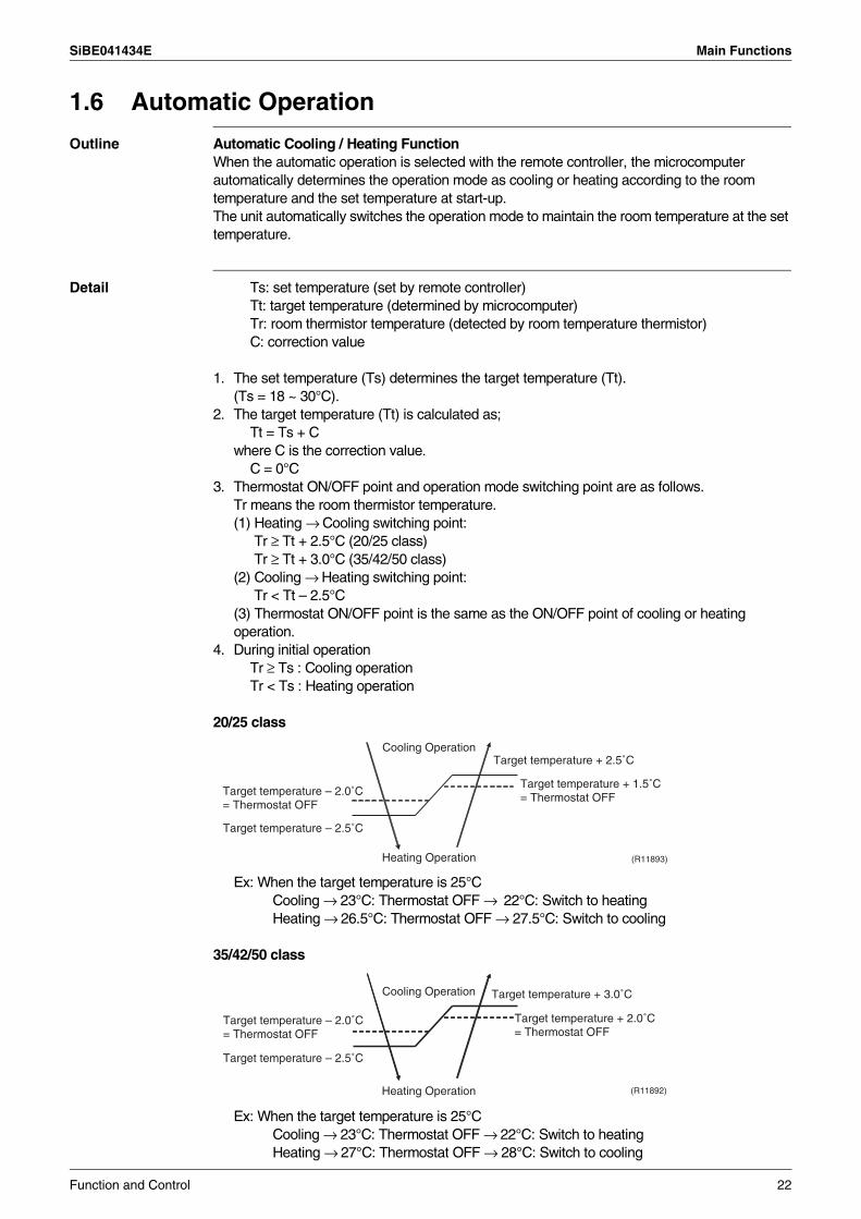
Outline Automatic Cooling / Heating FunctionWhen the automatic operation is selected with the remote controller, the microcomputer automatically determines the operation mode as cooling or heating according to the room temperature and the set temperature at start-up.The unit automatically switches the operation mode to maintain the room temperature at the set temperature.
Detail Ts: set temperature (set by remote controller)Tt: target temperature (determined by microcomputer)Tr: room thermistor temperature (detected by room temperature thermistor)C: correction value
1. The set temperature (Ts) determines the target temperature (Tt). (Ts = 18 ~ 30°C).
2. The target temperature (Tt) is calculated as; Tt = Ts + C
where C is the correction value.C = 0°C
3. Thermostat ON/OFF point and operation mode switching point are as follows.Tr means the room thermistor temperature.(1) Heating → Cooling switching point:
Tr ≥ Tt + 2.5°C (20/25 class)Tr ≥ Tt + 3.0°C (35/42/50 class)
(2) Cooling → Heating switching point: Tr < Tt – 2.5°C
(3) Thermostat ON/OFF point is the same as the ON/OFF point of cooling or heating operation.
4. During initial operationTr ≥ Ts : Cooling operationTr < Ts : Heating operation
20/25 class
Ex: When the target temperature is 25°CCooling → 23°C: Thermostat OFF → 22°C: Switch to heatingHeating → 26.5°C: Thermostat OFF → 27.5°C: Switch to cooling
35/42/50 class
Ex: When the target temperature is 25°CCooling → 23°C: Thermostat OFF → 22°C: Switch to heatingHeating → 27°C: Thermostat OFF → 28°C: Switch to cooling
(R11893)
Target temperature + 2.5˚C
Heating Operation
Target temperature – 2.5˚C
Cooling Operation
Target temperature – 2.0˚C = Thermostat OFF
Target temperature + 1.5˚C = Thermostat OFF
Target temperature + 3.0˚C
Heating Operation
Target temperature – 2.5˚C
Cooling Operation
(R11892)
Target temperature – 2.0˚C = Thermostat OFF
Target temperature + 2.0˚C = Thermostat OFF
Function and Control 22
Main Functions SiBE041434E
1.7 Thermostat Control
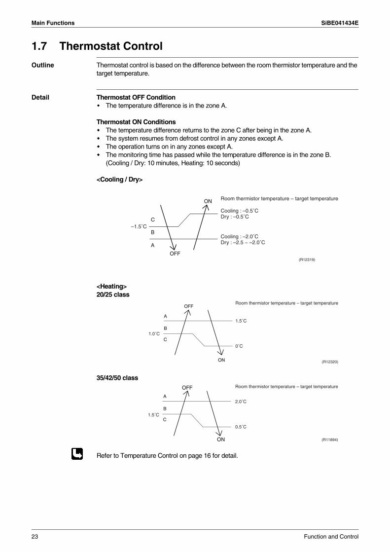
Outline Thermostat control is based on the difference between the room thermistor temperature and the target temperature.
Detail Thermostat OFF ConditionThe temperature difference is in the zone A.
Thermostat ON ConditionsThe temperature difference returns to the zone C after being in the zone A.The system resumes from defrost control in any zones except A.The operation turns on in any zones except A.The monitoring time has passed while the temperature difference is in the zone B.(Cooling / Dry: 10 minutes, Heating: 10 seconds)
<Cooling / Dry>
<Heating>20/25 class
35/42/50 class
Refer to Temperature Control on page 16 for detail.
B
A
OFF
ON
C
Room thermistor temperature – target temperature
–1.5˚C
(R12319)
Cooling : –0.5˚CDry : –0.5˚C
Cooling : –2.0˚CDry : –2.5 ~ –2.0˚C
B
A
OFF
ON
C
1.5˚C
1.0˚C
Room thermistor temperature – target temperature
0˚C
(R12320)
OFF
ON
B
A
C1.5˚C
2.0˚C
0.5˚C
Room thermistor temperature – target temperature
(R11894)
23 Function and Control
SiBE041434E Main Functions
1.8 NIGHT SET Mode
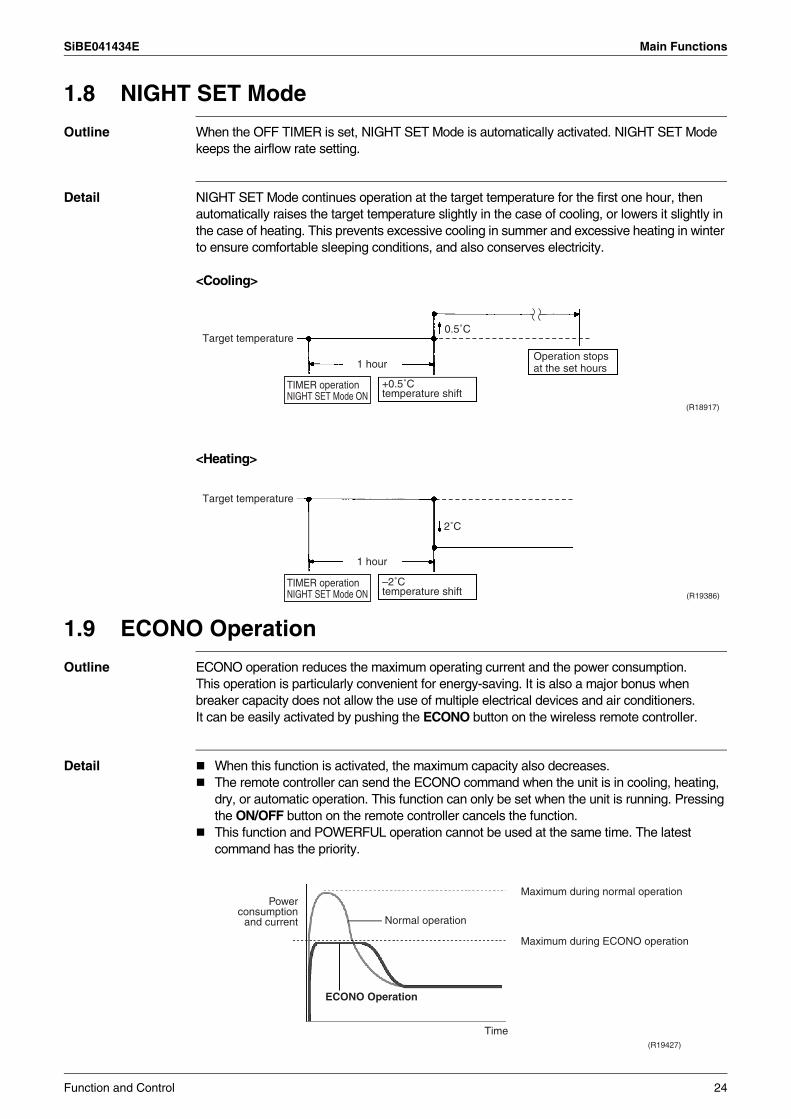
Outline When the OFF TIMER is set, NIGHT SET Mode is automatically activated. NIGHT SET Mode keeps the airflow rate setting.
Detail NIGHT SET Mode continues operation at the target temperature for the first one hour, then automatically raises the target temperature slightly in the case of cooling, or lowers it slightly in the case of heating. This prevents excessive cooling in summer and excessive heating in winter to ensure comfortable sleeping conditions, and also conserves electricity.
<Cooling>
<Heating>
1.9 ECONO Operation
Outline ECONO operation reduces the maximum operating current and the power consumption.This operation is particularly convenient for energy-saving. It is also a major bonus when breaker capacity does not allow the use of multiple electrical devices and air conditioners.It can be easily activated by pushing the ECONO button on the wireless remote controller.
Detail When this function is activated, the maximum capacity also decreases.The remote controller can send the ECONO command when the unit is in cooling, heating, dry, or automatic operation. This function can only be set when the unit is running. Pressing the ON/OFF button on the remote controller cancels the function.This function and POWERFUL operation cannot be used at the same time. The latest command has the priority.
(R18917)
TIMER operation NIGHT SET Mode ON
Target temperature
+0.5˚C temperature shift
Operation stops at the set hours
0.5˚C
1 hour
TIMER operation NIGHT SET Mode ON
Target temperature
–2˚C temperature shift
1 hour
2˚C
(R19386)
ECONO Operation
(R19427)
Normal operation
Maximum during normal operation
Maximum during ECONO operation
Time
Power consumption
and current
Function and Control 24
Main Functions SiBE041434E
1.10 INTELLIGENT EYE Operation (20/25 Class)
Outline This function detects the presence of humans in the room with a motion sensor (INTELLIGENT EYE) and reduces the capacity when there is nobody in the room in order to save electricity.
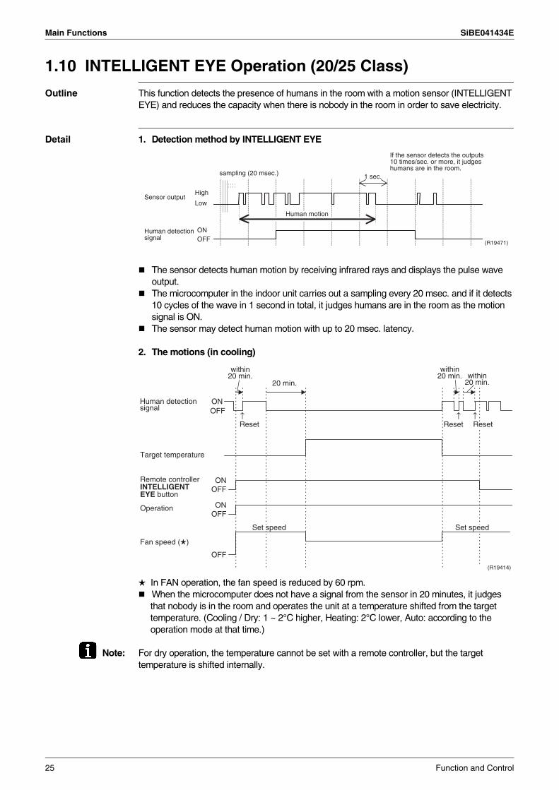
Detail 1. Detection method by INTELLIGENT EYE
The sensor detects human motion by receiving infrared rays and displays the pulse wave output.The microcomputer in the indoor unit carries out a sampling every 20 msec. and if it detects 10 cycles of the wave in 1 second in total, it judges humans are in the room as the motion signal is ON.The sensor may detect human motion with up to 20 msec. latency.
2. The motions (in cooling)
In FAN operation, the fan speed is reduced by 60 rpm.When the microcomputer does not have a signal from the sensor in 20 minutes, it judges that nobody is in the room and operates the unit at a temperature shifted from the target temperature. (Cooling / Dry: 1 ~ 2°C higher, Heating: 2°C lower, Auto: according to the operation mode at that time.)
Note: For dry operation, the temperature cannot be set with a remote controller, but the target temperature is shifted internally.
1 sec.sampling (20 msec.)
High
Low
ONOFF
Sensor output
(R19471)
Human detection signal
If the sensor detects the outputs 10 times/sec. or more, it judges humans are in the room.
Human motion
ONOFF
Reset Reset Reset
20 min.
ONOFF
ONOFF
Operation
OFF
Fan speed ( )
Set speed Set speed
Target temperature
(R19414)
Remote controller INTELLIGENT EYE button
Human detection signal
↑ ↑ ↑
within 20 min.
within 20 min. within
20 min.
25 Function and Control
SiBE041434E Main Functions
1.11 2-Area INTELLIGENT EYE Operation (35/42/50 Class)
Outline The following functions can be performed by a motion sensor (INTELLIGENT EYE).1. Reduction of the capacity when there is nobody in the room in order to save electricity
(energy saving operation)2. Dividing the room into plural areas and detecting existence of humans in each area.
Moving the airflow direction to the area with no human automatically to avoid direct airflow on humans.
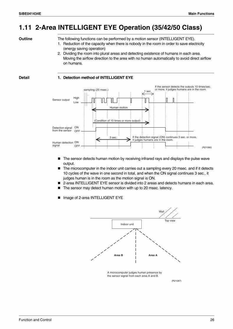
Detail 1. Detection method of INTELLIGENT EYE
The sensor detects human motion by receiving infrared rays and displays the pulse wave output.The microcomputer in the indoor unit carries out a sampling every 20 msec. and if it detects 10 cycles of the wave in one second in total, and when the ON signal continues 3 sec., it judges human is in the room as the motion signal is ON.2-area INTELLIGENT EYE sensor is divided into 2 areas and detects humans in each area.The sensor may detect human motion with up to 20 msec. latency.
Image of 2-area INTELLIGENT EYE
1 sec.sampling (20 msec.)
High
Low
ONOFF
Sensor output
ONOFF
(R21086)
(Condition of 10 times or more output)
Human motion
3 sec.
If the sensor detects the outputs 10 times/sec. or more, it judges humans are in the room.
If the detection signal (ON) continues 3 sec. or more, it judges humans are in the room.
Detection signal from the sensor
Human detection signal
Top view
(R21087)
Indoor unit
Wall
Area AArea B
A microcomputer judges human presence by the sensor signal from each area A and B.
Function and Control 26
Main Functions SiBE041434E
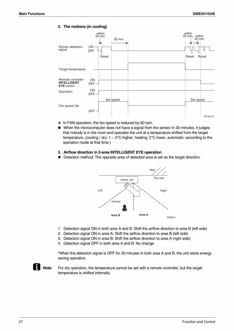
2. The motions (in cooling)
In FAN operation, the fan speed is reduced by 60 rpm.When the microcomputer does not have a signal from the sensor in 20 minutes, it judges that nobody is in the room and operates the unit at a temperature shifted from the target temperature. (cooling / dry: 1 ~ 2°C higher, heating: 2°C lower, automatic: according to the operation mode at that time.)
3. Airflow direction in 2-area INTELLIGENT EYE operationDetection method: The opposite area of detected area is set as the target direction.
1. Detection signal ON in both area A and B: Shift the airflow direction to area B (left side)2. Detection signal ON in area A: Shift the airflow direction to area B (left side)3. Detection signal ON in area B: Shift the airflow direction to area A (right side)4. Detection signal OFF in both area A and B: No change
*When the detection signal is OFF for 20 minutes in both area A and B, the unit starts energy saving operation.
Note: For dry operation, the temperature cannot be set with a remote controller, but the target temperature is shifted internally.
ONOFF
Reset Reset Reset
20 min.
ONOFF
ONOFF
Operation
OFF
Fan speed ( )
Set speed Set speed
Target temperature
(R19414)
Remote controller INTELLIGENT EYE button
Human detection signal
↑ ↑ ↑
within 20 min.
within 20 min. within
20 min.
Top view
Wall
Indoor unit
Area AArea B
Left Right
Human
(R3853)
27 Function and Control
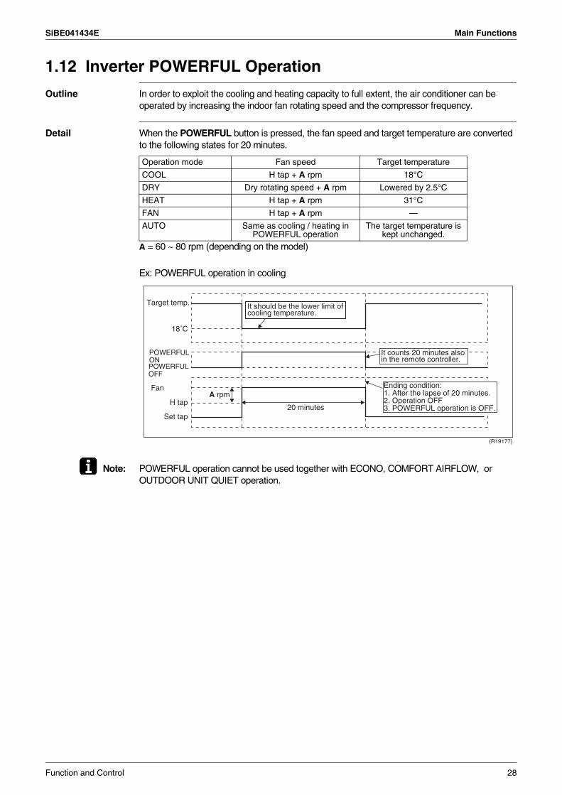
SiBE041434E Main Functions
1.12 Inverter POWERFUL Operation
Outline In order to exploit the cooling and heating capacity to full extent, the air conditioner can be operated by increasing the indoor fan rotating speed and the compressor frequency.
Detail When the POWERFUL button is pressed, the fan speed and target temperature are converted to the following states for 20 minutes.
A = 60 ~ 80 rpm (depending on the model)
Ex: POWERFUL operation in cooling
Note: POWERFUL operation cannot be used together with ECONO, COMFORT AIRFLOW, or OUTDOOR UNIT QUIET operation.
Operation mode Fan speed Target temperature
COOL H tap + A rpm 18°C
DRY Dry rotating speed + A rpm Lowered by 2.5°C
HEAT H tap + A rpm 31°C
FAN H tap + A rpm —
AUTO Same as cooling / heating in POWERFUL operation
The target temperature is kept unchanged.
(R19177)
Target temp.
FanA rpm
18˚C
H tap
Set tap20 minutes
It should be the lower limit of cooling temperature.
It counts 20 minutes also in the remote controller.
POWERFUL ONPOWERFUL OFF
Ending condition:1. After the lapse of 20 minutes.2. Operation OFF3. POWERFUL operation is OFF.
Function and Control 28
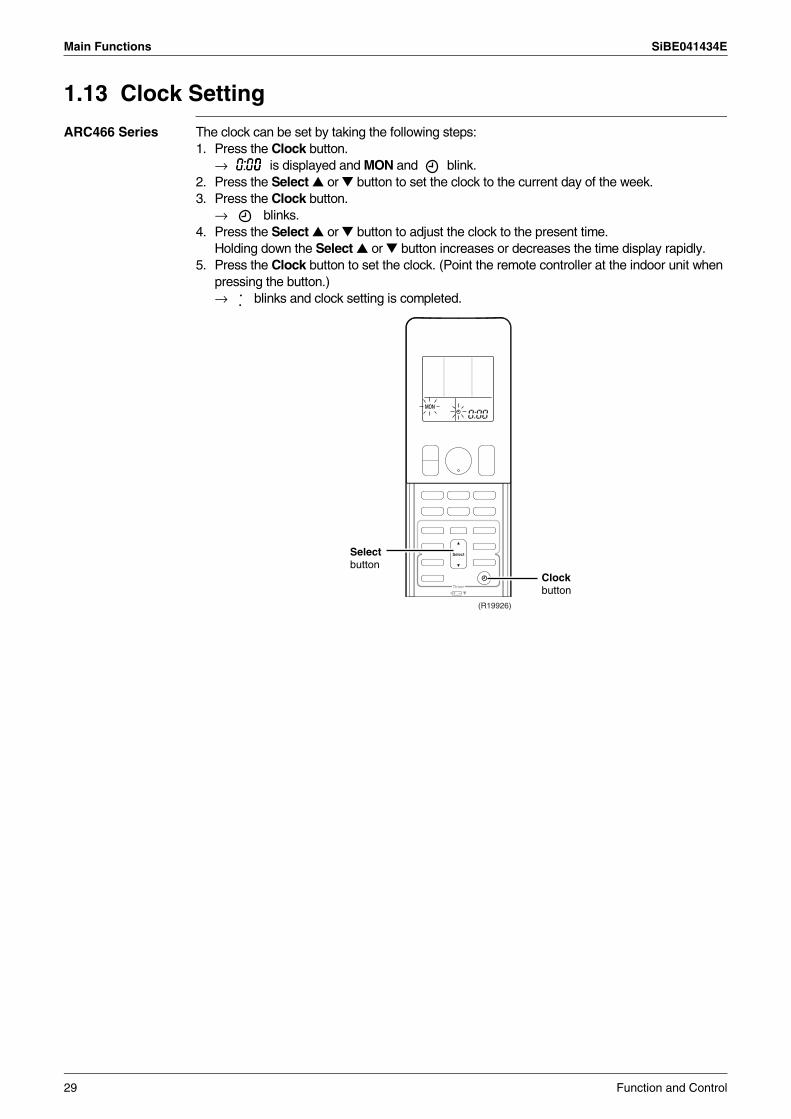
Main Functions SiBE041434E
1.13 Clock Setting
ARC466 Series The clock can be set by taking the following steps:1. Press the Clock button.
→ is displayed and MON and blink.2. Press the Select or button to set the clock to the current day of the week.3. Press the Clock button.
→ blinks.4. Press the Select or button to adjust the clock to the present time.
Holding down the Select or button increases or decreases the time display rapidly.5. Press the Clock button to set the clock. (Point the remote controller at the indoor unit when
pressing the button.)→ blinks and clock setting is completed.
(R19926)
0:00
Select button
Clock button
29 Function and Control
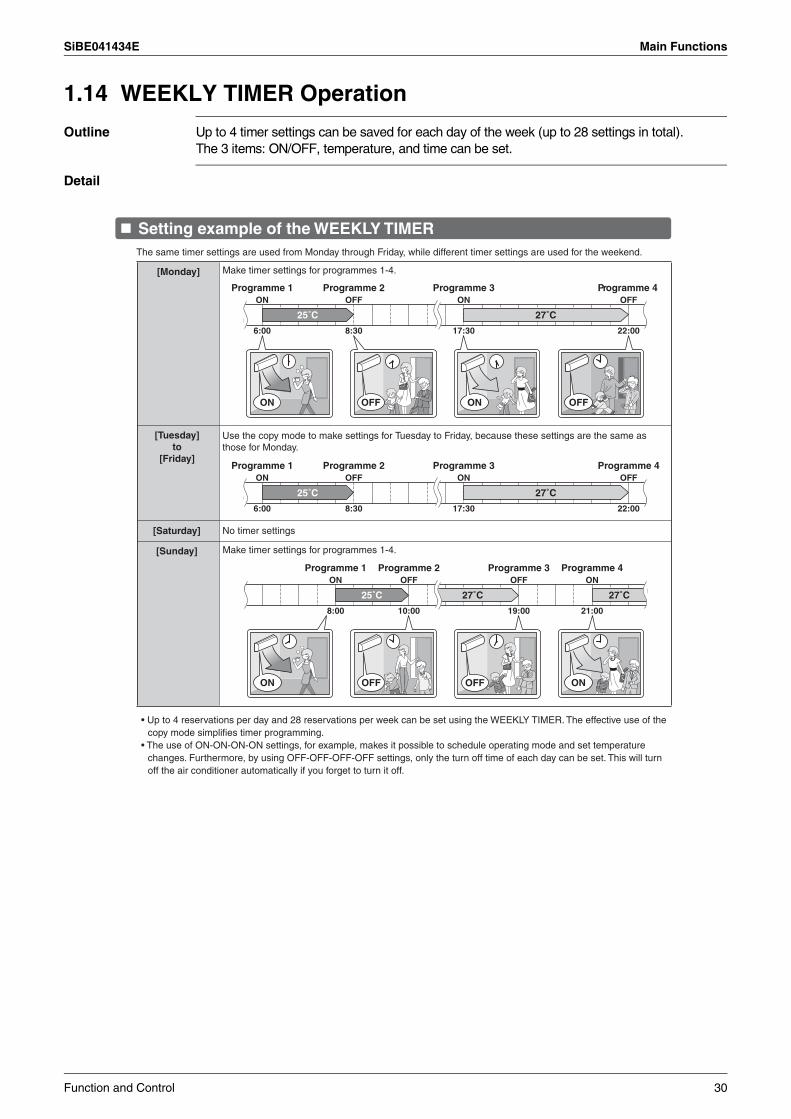
SiBE041434E Main Functions
1.14 WEEKLY TIMER Operation
Outline Up to 4 timer settings can be saved for each day of the week (up to 28 settings in total). The 3 items: ON/OFF, temperature, and time can be set.
Detail
Setting example of the WEEKLY TIMER
6:00 8:30 17:30 22:00
25˚C 27˚C
ON ON OFFOFF
Programme 1 Programme 2 Programme 3 Programme 4ON OFF ON OFF
6:00 8:30 17:30 22:00
25˚C 27˚C
Programme 1 Programme 2 Programme 3 Programme 4ON OFF ON OFF
Make timer settings for programmes 1-4.
8:00 10:00 19:00 21:00
27˚C 27˚C25˚C
ON ONOFFOFF
ON OFF OFF ONProgramme 1 Programme 2 Programme 3 Programme 4
• Up to 4 reservations per day and 28 reservations per week can be set using the WEEKLY TIMER. The effective use of the copy mode simplifies timer programming.
• The use of ON-ON-ON-ON settings, for example, makes it possible to schedule operating mode and set temperature changes. Furthermore, by using OFF-OFF-OFF-OFF settings, only the turn off time of each day can be set. This will turn off the air conditioner automatically if you forget to turn it off.
The same timer settings are used from Monday through Friday, while different timer settings are used for the weekend.
[Monday] Make timer settings for programmes 1-4.
[Tuesday] to
[Friday]
[Saturday]
[Sunday]
Use the copy mode to make settings for Tuesday to Friday, because these settings are the same as those for Monday.
No timer settings
Function and Control 30
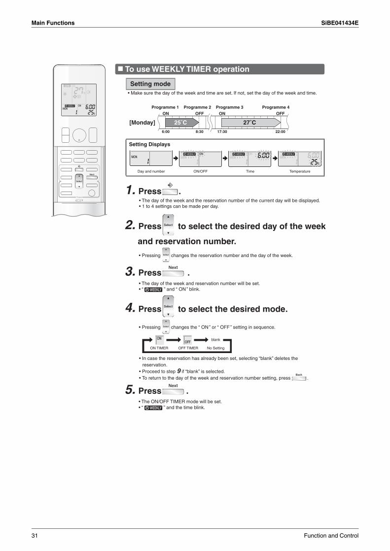
Main Functions SiBE041434E
Setting mode
6:00 8:30 17:30 22:00
25˚C 27˚C
Programme 1 Programme 2 Programme 3 Programme 4ON OFF ON OFF
[Monday]
Setting Displays
Day and number ON/OFF Time Temperature
1. Press .
• Pressing changes the reservation number and the day of the week.
4. Press to select the desired mode.
• Pressing changes the “ ON ” or “ OFF ” setting in sequence.
ON TIMER OFF TIMER No Setting
blank
5. Press .
To use WEEKLY TIMER operation
• Make sure the day of the week and time are set. If not, set the day of the week and time.
• The day of the week and the reservation number of the current day will be displayed.• 1 to 4 settings can be made per day.
2. Press to select the desired day of the week
and reservation number.
• The day of the week and reservation number will be set.• “ ” and “ ON ” blink.
3. Press .
• In case the reservation has already been set, selecting “blank” deletes the reservation.
• Proceed to step 9 if “blank” is selected.• To return to the day of the week and reservation number setting, press .
• The ON/OFF TIMER mode will be set. • “ ” and the time blink.
31 Function and Control
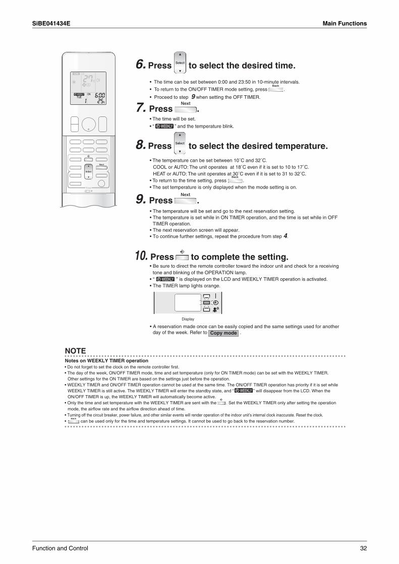
SiBE041434E Main Functions
6. Press to select the desired time.
7. Press .
8. Press to select the desired temperature.
9. Press .
• The time can be set between 0:00 and 23:50 in 10-minute intervals.
• To return to the ON/OFF TIMER mode setting, press .
• Proceed to step 9 when setting the OFF TIMER.
• The time will be set.
• “ ” and the temperature blink.
• The temperature can be set between 10˚C and 32˚C.COOL or AUTO: The unit operates at 18˚C even if it is set to 10 to 17˚C.HEAT or AUTO: The unit operates at 30˚C even if it is set to 31 to 32˚C.
• To return to the time setting, press .• The set temperature is only displayed when the mode setting is on.
• The temperature will be set and go to the next reservation setting.• The temperature is set while in ON TIMER operation, and the time is set while in OFF
TIMER operation.• The next reservation screen will appear.• To continue further settings, repeat the procedure from step 4.
10. Press to complete the setting.
Display
Copy mode
• Be sure to direct the remote controller toward the indoor unit and check for a receiving tone and blinking of the OPERATION lamp.
• “ ” is displayed on the LCD and WEEKLY TIMER operation is activated.• The TIMER lamp lights orange.
• A reservation made once can be easily copied and the same settings used for another day of the week. Refer to .
NOTENotes on WEEKLY TIMER operation• Do not forget to set the clock on the remote controller first. • The day of the week, ON/OFF TIMER mode, time and set temperature (only for ON TIMER mode) can be set with the WEEKLY TIMER.
Other settings for the ON TIMER are based on the settings just before the operation.• WEEKLY TIMER and ON/OFF TIMER operation cannot be used at the same time. The ON/OFF TIMER operation has priority if it is set while
WEEKLY TIMER is still active. The WEEKLY TIMER will enter the standby state, and “ ” will disappear from the LCD. When the ON/OFF TIMER is up, the WEEKLY TIMER will automatically become active.
• Only the time and set temperature with the WEEKLY TIMER are sent with the . Set the WEEKLY TIMER only after setting the operation mode, the airflow rate and the airflow direction ahead of time.
• Turning off the circuit breaker, power failure, and other similar events will render operation of the indoor unit’s internal clock inaccurate. Reset the clock.• can be used only for the time and temperature settings. It cannot be used to go back to the reservation number.
Function and Control 32
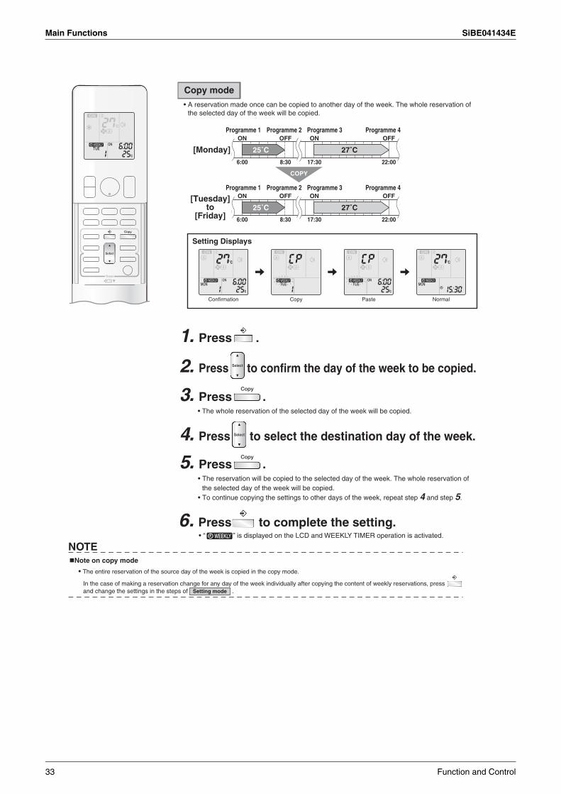
Main Functions SiBE041434E
6. Press to complete the setting.
NOTENote on copy mode
Setting mode
• “ ” is displayed on the LCD and WEEKLY TIMER operation is activated.
• The entire reservation of the source day of the week is copied in the copy mode.
In the case of making a reservation change for any day of the week individually after copying the content of weekly reservations, press and change the settings in the steps of .
Copy mode• A reservation made once can be copied to another day of the week. The whole reservation of
the selected day of the week will be copied.
6:00 8:30 17:30 22:00
25˚C 27˚C
6:00 8:30 17:30 22:00
25˚C 27˚C
COPY
Programme 1 Programme 2 Programme 3 Programme 4ON OFF ON OFF
[Monday]
Programme 1 Programme 2 Programme 3 Programme 4ON OFF ON OFF[Tuesday]
to [Friday]
Setting Displays
Confirmation Copy Paste Normal
1. Press .
2. Press to confirm the day of the week to be copied.
3. Press .• The whole reservation of the selected day of the week will be copied.
4. Press to select the destination day of the week.
5. Press .• The reservation will be copied to the selected day of the week. The whole reservation of
the selected day of the week will be copied. • To continue copying the settings to other days of the week, repeat step 4 and step 5.
33 Function and Control
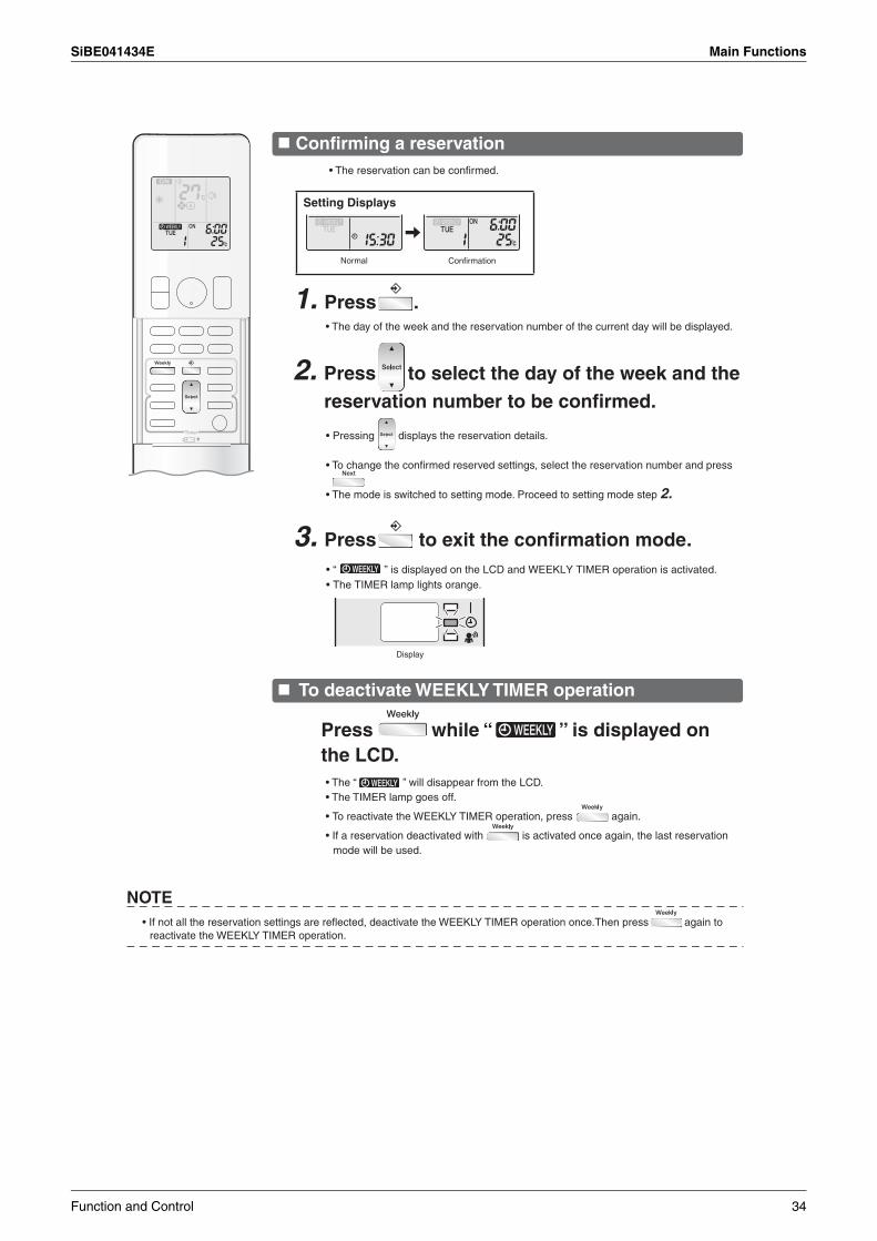
SiBE041434E Main Functions
Confirming a reservation
Setting Displays
Normal
1. Press .
3. Press to exit the confirmation mode.
To deactivate WEEKLY TIMER operation
NOTE
• The day of the week and the reservation number of the current day will be displayed.
Confirmation
• The reservation can be confirmed.
2. Press to select the day of the week and the reservation number to be confirmed.
• Pressing displays the reservation details.
• To change the confirmed reserved settings, select the reservation number and press
• The mode is switched to setting mode. Proceed to setting mode step 2.
Press while “ ” is displayed on the LCD.• The “ ” will disappear from the LCD.• The TIMER lamp goes off.
• To reactivate the WEEKLY TIMER operation, press again.
• If a reservation deactivated with is activated once again, the last reservation mode will be used.
• If not all the reservation settings are reflected, deactivate the WEEKLY TIMER operation once.Then press again to reactivate the WEEKLY TIMER operation.
Display
• “ ” is displayed on the LCD and WEEKLY TIMER operation is activated. • The TIMER lamp lights orange.
Function and Control 34
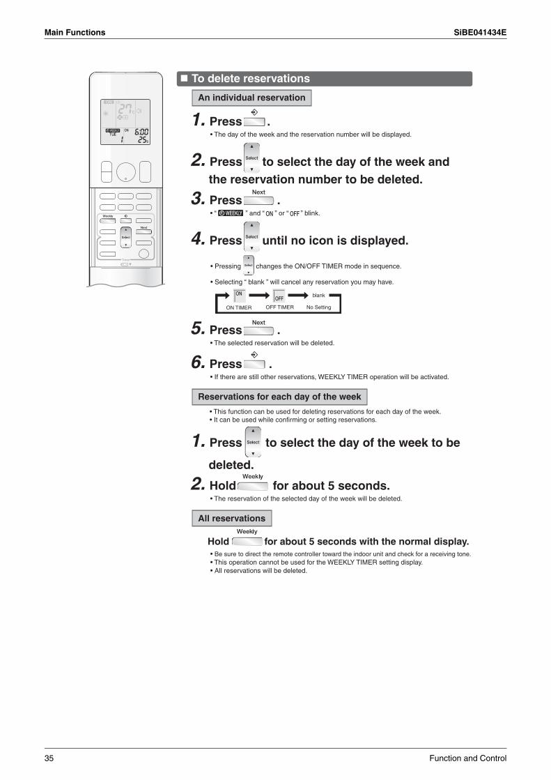
Main Functions SiBE041434E
To delete reservations
An individual reservation
1. Press .• The day of the week and the reservation number will be displayed.
3. Press .• “ ” and “ ” or “ ” blink.
4. Press until no icon is displayed.
No Setting
blank
5. Press .• The selected reservation will be deleted.
6. Press .• If there are still other reservations, WEEKLY TIMER operation will be activated.
Reservations for each day of the week
2. Hold for about 5 seconds.• The reservation of the selected day of the week will be deleted.
All reservations
Hold for about 5 seconds with the normal display.
2. Press to select the day of the week and the reservation number to be deleted.
• Pressing changes the ON/OFF TIMER mode in sequence.
• Selecting “ blank ” will cancel any reservation you may have.
ON TIMER OFF TIMER
• This function can be used for deleting reservations for each day of the week.• It can be used while confirming or setting reservations.
1. Press to select the day of the week to be
deleted.
• Be sure to direct the remote controller toward the indoor unit and check for a receiving tone.• This operation cannot be used for the WEEKLY TIMER setting display.• All reservations will be deleted.
35 Function and Control
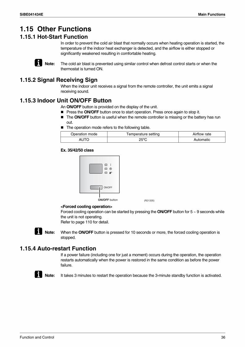
SiBE041434E Main Functions
1.15 Other Functions1.15.1 Hot-Start Function
In order to prevent the cold air blast that normally occurs when heating operation is started, the temperature of the indoor heat exchanger is detected, and the airflow is either stopped or significantly weakened resulting in comfortable heating.
Note: The cold air blast is prevented using similar control when defrost control starts or when the thermostat is turned ON.
1.15.2 Signal Receiving SignWhen the indoor unit receives a signal from the remote controller, the unit emits a signal receiving sound.
1.15.3 Indoor Unit ON/OFF ButtonAn ON/OFF button is provided on the display of the unit.
Press the ON/OFF button once to start operation. Press once again to stop it.The ON/OFF button is useful when the remote controller is missing or the battery has run out.The operation mode refers to the following table.
Ex. 35/42/50 class
<Forced cooling operation>Forced cooling operation can be started by pressing the ON/OFF button for 5 ~ 9 seconds while the unit is not operating.Refer to page 110 for detail.
Note: When the ON/OFF button is pressed for 10 seconds or more, the forced cooling operation is stopped.
1.15.4 Auto-restart FunctionIf a power failure (including one for just a moment) occurs during the operation, the operation restarts automatically when the power is restored in the same condition as before the power failure.
Note: It takes 3 minutes to restart the operation because the 3-minute standby function is activated.
Operation mode Temperature setting Airflow rate
AUTO 25ºC Automatic
ON/OFF button (R21335)
Function and Control 36
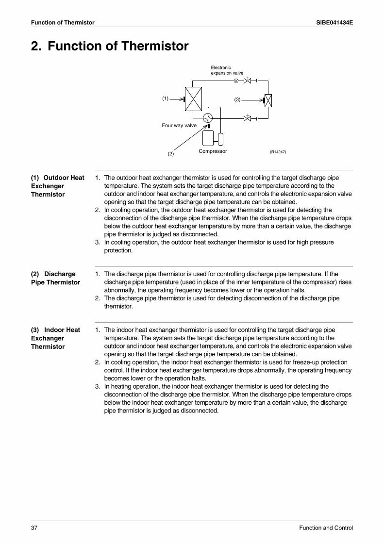
Function of Thermistor SiBE041434E
2. Function of Thermistor
(1) Outdoor Heat Exchanger Thermistor
1. The outdoor heat exchanger thermistor is used for controlling the target discharge pipe temperature. The system sets the target discharge pipe temperature according to the outdoor and indoor heat exchanger temperature, and controls the electronic expansion valve opening so that the target discharge pipe temperature can be obtained.
2. In cooling operation, the outdoor heat exchanger thermistor is used for detecting the disconnection of the discharge pipe thermistor. When the discharge pipe temperature drops below the outdoor heat exchanger temperature by more than a certain value, the discharge pipe thermistor is judged as disconnected.
3. In cooling operation, the outdoor heat exchanger thermistor is used for high pressure protection.
(2) Discharge Pipe Thermistor
1. The discharge pipe thermistor is used for controlling discharge pipe temperature. If the discharge pipe temperature (used in place of the inner temperature of the compressor) rises abnormally, the operating frequency becomes lower or the operation halts.
2. The discharge pipe thermistor is used for detecting disconnection of the discharge pipe thermistor.
(3) Indoor Heat Exchanger Thermistor
1. The indoor heat exchanger thermistor is used for controlling the target discharge pipe temperature. The system sets the target discharge pipe temperature according to the outdoor and indoor heat exchanger temperature, and controls the electronic expansion valve opening so that the target discharge pipe temperature can be obtained.
2. In cooling operation, the indoor heat exchanger thermistor is used for freeze-up protection control. If the indoor heat exchanger temperature drops abnormally, the operating frequency becomes lower or the operation halts.
3. In heating operation, the indoor heat exchanger thermistor is used for detecting the disconnection of the discharge pipe thermistor. When the discharge pipe temperature drops below the indoor heat exchanger temperature by more than a certain value, the discharge pipe thermistor is judged as disconnected.
Four way valve
Compressor (R14247)
(3)
(2)
Electronic expansion valve
(1)
37 Function and Control
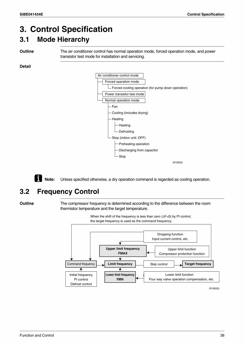
SiBE041434E Control Specification
3. Control Specification3.1 Mode Hierarchy
Outline The air conditioner control has normal operation mode, forced operation mode, and power transistor test mode for installation and servicing.
Detail
Note: Unless specified otherwise, a dry operation command is regarded as cooling operation.
3.2 Frequency Control
Outline The compressor frequency is determined according to the difference between the room thermistor temperature and the target temperature.
Air conditioner control mode
Forced operation mode
Forced cooling operation (for pump down operation)
Power transistor test mode
Normal operation mode
Fan
Cooling (includes drying)
Heating
Heating
Defrosting
Stop (indoor unit: OFF)
Preheating operation
Discharging from capacitor
Stop
(R19522)
Command frequency Limit frequency Skip control
Lower limit function Four way valve operation compensation, etc.
Initial frequency PI control
Defrost control
Dropping function Input current control, etc.
Upper limit function Compressor protection function
Upper limit frequency FMAX
Lower limit frequency FMIN
Target frequency
(R18023)
When the shift of the frequency is less than zero (∆F<0) by PI control, the target frequency is used as the command frequency.
Function and Control 38
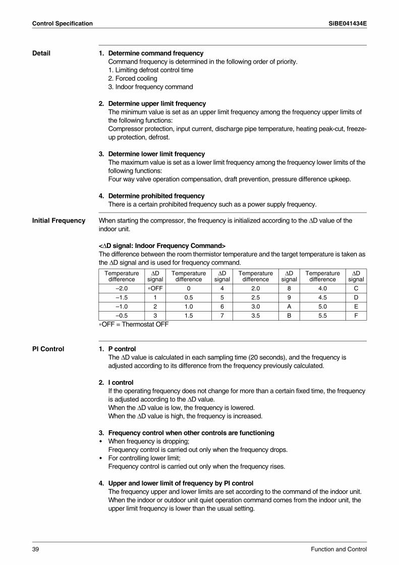
Control Specification SiBE041434E
Detail 1. Determine command frequencyCommand frequency is determined in the following order of priority.1. Limiting defrost control time2. Forced cooling3. Indoor frequency command
2. Determine upper limit frequencyThe minimum value is set as an upper limit frequency among the frequency upper limits of the following functions: Compressor protection, input current, discharge pipe temperature, heating peak-cut, freeze-up protection, defrost.
3. Determine lower limit frequencyThe maximum value is set as a lower limit frequency among the frequency lower limits of the following functions: Four way valve operation compensation, draft prevention, pressure difference upkeep.
4. Determine prohibited frequencyThere is a certain prohibited frequency such as a power supply frequency.
Initial Frequency When starting the compressor, the frequency is initialized according to the ∆D value of the indoor unit.
<∆D signal: Indoor Frequency Command>The difference between the room thermistor temperature and the target temperature is taken as the ∆D signal and is used for frequency command.
∗OFF = Thermostat OFF
PI Control 1. P controlThe ∆D value is calculated in each sampling time (20 seconds), and the frequency is adjusted according to its difference from the frequency previously calculated.
2. I controlIf the operating frequency does not change for more than a certain fixed time, the frequency is adjusted according to the ∆D value.When the ∆D value is low, the frequency is lowered.When the ∆D value is high, the frequency is increased.
3. Frequency control when other controls are functioningWhen frequency is dropping; Frequency control is carried out only when the frequency drops.For controlling lower limit; Frequency control is carried out only when the frequency rises.
4. Upper and lower limit of frequency by PI control The frequency upper and lower limits are set according to the command of the indoor unit.When the indoor or outdoor unit quiet operation command comes from the indoor unit, the upper limit frequency is lower than the usual setting.
Temperature difference
∆D signal
Temperature difference
∆D signal
Temperature difference
∆D signal
Temperature difference
∆D signal
–2.0 ∗OFF 0 4 2.0 8 4.0 C
–1.5 1 0.5 5 2.5 9 4.5 D
–1.0 2 1.0 6 3.0 A 5.0 E
–0.5 3 1.5 7 3.5 B 5.5 F
39 Function and Control
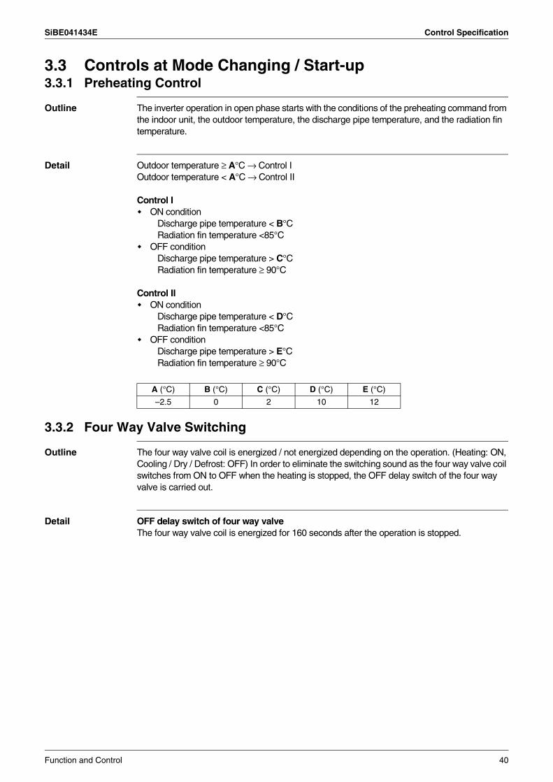
SiBE041434E Control Specification
3.3 Controls at Mode Changing / Start-up3.3.1 Preheating Control
Outline The inverter operation in open phase starts with the conditions of the preheating command from the indoor unit, the outdoor temperature, the discharge pipe temperature, and the radiation fin temperature.
Detail Outdoor temperature ≥ A°C → Control IOutdoor temperature < A°C → Control II
Control ION condition
Discharge pipe temperature < B°CRadiation fin temperature <85°C
OFF conditionDischarge pipe temperature > C°CRadiation fin temperature ≥ 90°C
Control IION condition
Discharge pipe temperature < D°CRadiation fin temperature <85°C
OFF conditionDischarge pipe temperature > E°CRadiation fin temperature ≥ 90°C
3.3.2 Four Way Valve Switching
Outline The four way valve coil is energized / not energized depending on the operation. (Heating: ON, Cooling / Dry / Defrost: OFF) In order to eliminate the switching sound as the four way valve coil switches from ON to OFF when the heating is stopped, the OFF delay switch of the four way valve is carried out.
Detail OFF delay switch of four way valveThe four way valve coil is energized for 160 seconds after the operation is stopped.
A (°C) B (°C) C (°C) D (°C) E (°C)
–2.5 0 2 10 12
Function and Control 40
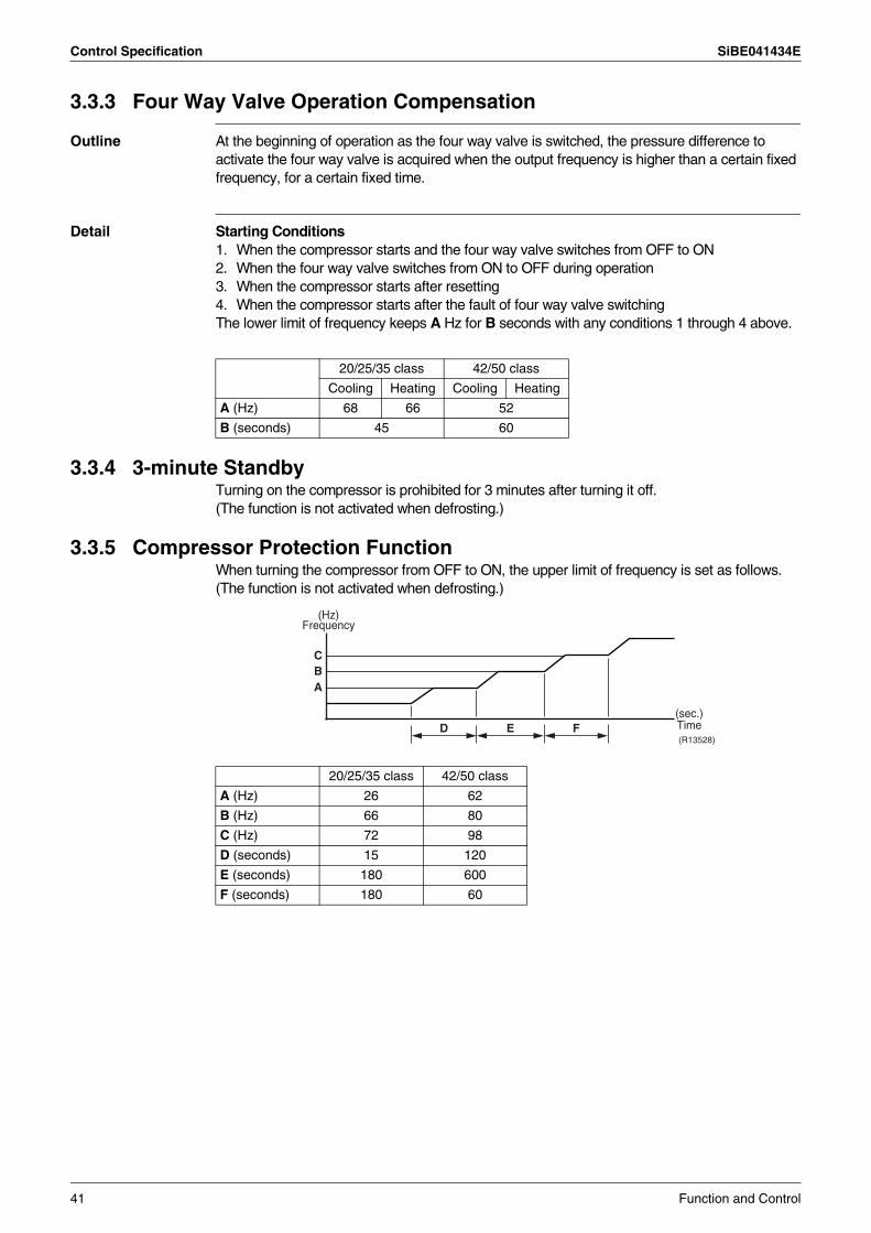
Control Specification SiBE041434E
3.3.3 Four Way Valve Operation Compensation
Outline At the beginning of operation as the four way valve is switched, the pressure difference to activate the four way valve is acquired when the output frequency is higher than a certain fixed frequency, for a certain fixed time.
Detail Starting Conditions1. When the compressor starts and the four way valve switches from OFF to ON2. When the four way valve switches from ON to OFF during operation3. When the compressor starts after resetting4. When the compressor starts after the fault of four way valve switchingThe lower limit of frequency keeps A Hz for B seconds with any conditions 1 through 4 above.
3.3.4 3-minute StandbyTurning on the compressor is prohibited for 3 minutes after turning it off.(The function is not activated when defrosting.)
3.3.5 Compressor Protection FunctionWhen turning the compressor from OFF to ON, the upper limit of frequency is set as follows. (The function is not activated when defrosting.)
20/25/35 class 42/50 class
Cooling Heating Cooling Heating
A (Hz) 68 66 52
B (seconds) 45 60
20/25/35 class 42/50 class
A (Hz) 26 62
B (Hz) 66 80
C (Hz) 72 98
D (seconds) 15 120
E (seconds) 180 600
F (seconds) 180 60
(sec.) Time(R13528)
(Hz) Frequency
CB
D E F
A
41 Function and Control
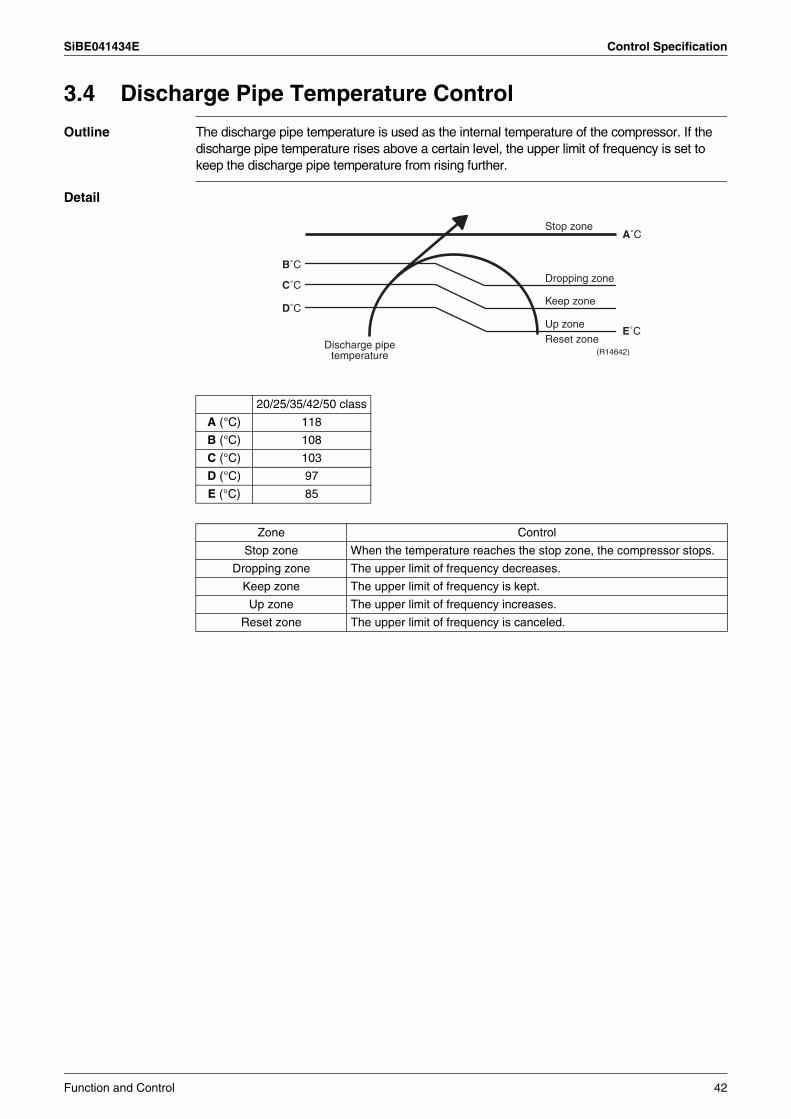
SiBE041434E Control Specification
3.4 Discharge Pipe Temperature Control
Outline The discharge pipe temperature is used as the internal temperature of the compressor. If the discharge pipe temperature rises above a certain level, the upper limit of frequency is set to keep the discharge pipe temperature from rising further.
Detail
20/25/35/42/50 class
A (°C) 118
B (°C) 108
C (°C) 103
D (°C) 97
E (°C) 85
Zone Control
Stop zone When the temperature reaches the stop zone, the compressor stops.
Dropping zone The upper limit of frequency decreases.
Keep zone The upper limit of frequency is kept.
Up zone The upper limit of frequency increases.
Reset zone The upper limit of frequency is canceled.
(R14642)Discharge pipe
temperature
Stop zone
Dropping zone
Keep zone
Up zoneReset zone
E˚C
A˚C
B˚C
C˚C
D˚C
Function and Control 42
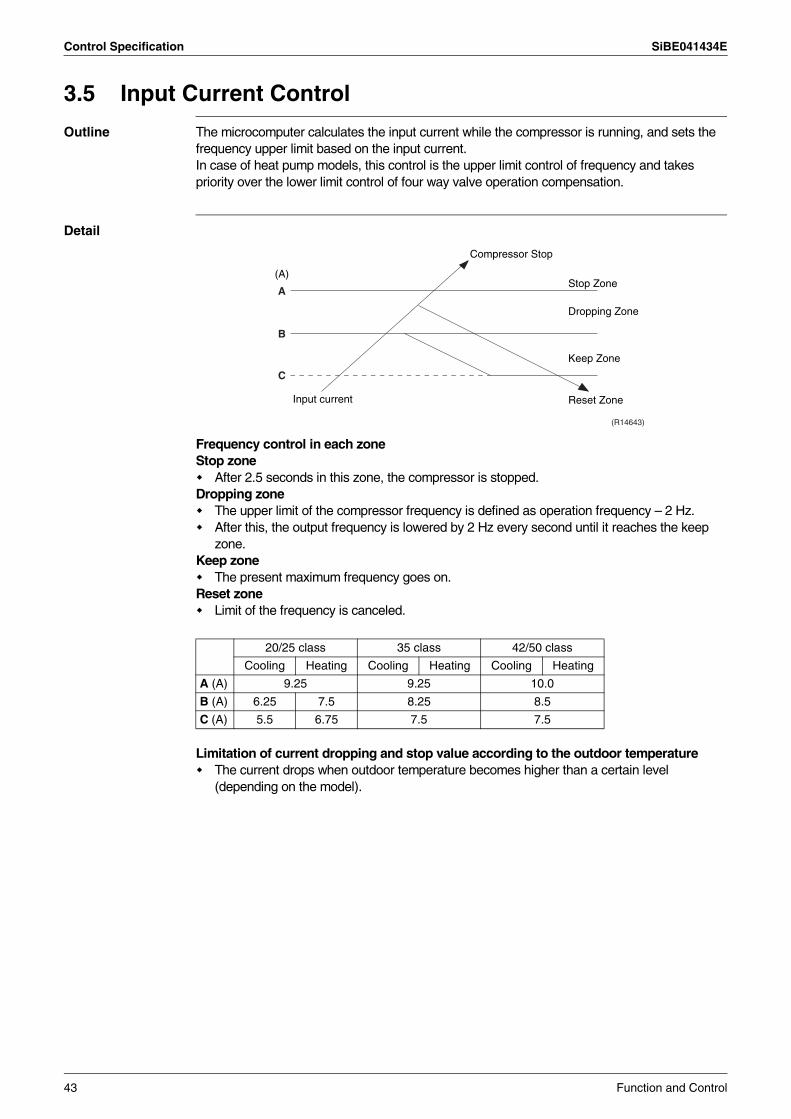
Control Specification SiBE041434E
3.5 Input Current Control
Outline The microcomputer calculates the input current while the compressor is running, and sets the frequency upper limit based on the input current.In case of heat pump models, this control is the upper limit control of frequency and takes priority over the lower limit control of four way valve operation compensation.
Detail
Frequency control in each zoneStop zone
After 2.5 seconds in this zone, the compressor is stopped.Dropping zone
The upper limit of the compressor frequency is defined as operation frequency – 2 Hz.After this, the output frequency is lowered by 2 Hz every second until it reaches the keep zone.
Keep zoneThe present maximum frequency goes on.
Reset zoneLimit of the frequency is canceled.
Limitation of current dropping and stop value according to the outdoor temperatureThe current drops when outdoor temperature becomes higher than a certain level (depending on the model).
20/25 class 35 class 42/50 class
Cooling Heating Cooling Heating Cooling Heating
A (A) 9.25 9.25 10.0
B (A) 6.25 7.5 8.25 8.5
C (A) 5.5 6.75 7.5 7.5
Compressor Stop
Input current
Dropping Zone
Stop Zone
Keep Zone
Reset Zone
(R14643)
A
(A)
B
C
43 Function and Control
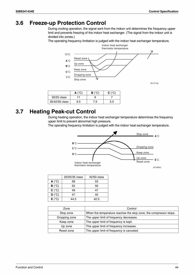
SiBE041434E Control Specification
3.6 Freeze-up Protection ControlDuring cooling operation, the signal sent from the indoor unit determines the frequency upper limit and prevents freezing of the indoor heat exchanger. (The signal from the indoor unit is divided into zones.)The operating frequency limitation is judged with the indoor heat exchanger temperature.
3.7 Heating Peak-cut ControlDuring heating operation, the indoor heat exchanger temperature determines the frequency upper limit to prevent abnormal high pressure.The operating frequency limitation is judged with the indoor heat exchanger temperature.
A (°C) B (°C) C (°C)
20/25 class 11 9 7
35/42/50 class 9.5 7.5 5.5
(R14718)
Reset zone
Indoor heat exchanger thermistor temperature
Up zone
Keep zone
Dropping zone
Stop zone0˚C
C˚C
B˚C
A˚C
13˚C
20/25/35 class 42/50 class
A (°C) 58 53
B (°C) 52 50
C (°C) 49 47
D (°C) 47 45
E (°C) 44.5 42.5
Zone Control
Stop zone When the temperature reaches the stop zone, the compressor stops.
Dropping zone The upper limit of frequency decreases.
Keep zone The upper limit of frequency is kept.
Up zone The upper limit of frequency increases.
Reset zone The upper limit of frequency is canceled.
Indoor heat exchanger thermistor temperature
Stop zone
Dropping zone
Keep zone
Up zoneReset zone
(R14645)
D˚C
C˚C
B˚C
A˚C
E˚C
Function and Control 44
Control Specification SiBE041434E
3.8 Outdoor Fan Control1. Fan ON control to cool down the electrical boxThe outdoor fan is turned ON when the electrical box temperature is high while the compressor is OFF.
2. Fan OFF control during defrostingThe outdoor fan is turned OFF during defrosting.
3. Fan OFF delay when stoppedThe outdoor fan is turned OFF 60 ~ 70 seconds after the compressor stops.
4. Fan speed control for pressure difference upkeepThe rotation speed of the outdoor fan is controlled for keeping the pressure difference during cooling operation with low outdoor temperature.
When the pressure difference is low, the rotation speed of the outdoor fan is reduced.When the pressure difference is high, the rotation speed of the outdoor fan is controlled as well as normal operation.
5. Fan speed control during forced cooling operationThe outdoor fan is controlled as well as normal operation during forced cooling operation.
6. Fan speed control during POWERFUL operationThe rotation speed of the outdoor fan is increased during POWERFUL operation.
7. Fan speed control during indoor / outdoor unit quiet operationThe rotation speed of the outdoor fan is reduced by the command of the indoor / outdoor unit quiet operation.
8. Fan ON/OFF control when operation (cooling, heating, dry) starts / stopsThe outdoor fan is turned ON when the operation starts. The outdoor fan is turned OFF when the operation stops.
3.9 Liquid Compression Protection Function
Outline In order to increase the dependability of the compressor, the compressor is stopped according to the outdoor temperature and temperature of the outdoor heat exchanger.
Detail Operation stops depending on the outdoor temperature.Compressor turns off under the conditions that the system is in cooling operation and outdoor temperature is below –12°C.
45 Function and Control
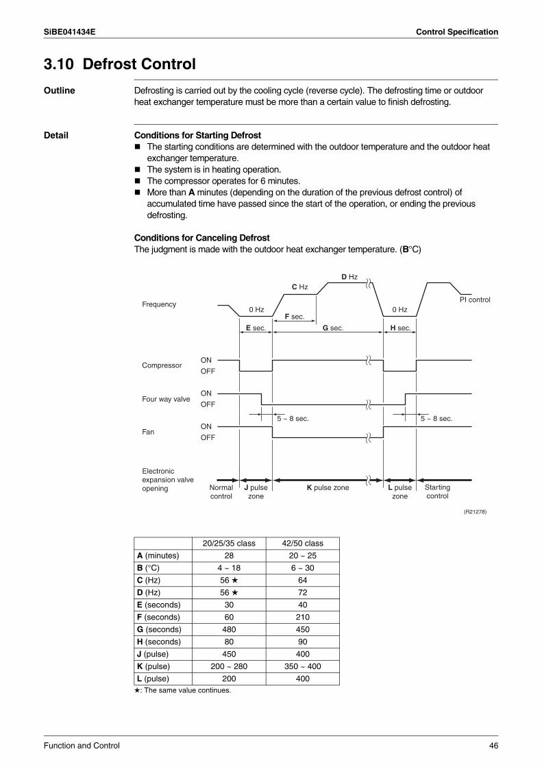
SiBE041434E Control Specification
3.10 Defrost Control
Outline Defrosting is carried out by the cooling cycle (reverse cycle). The defrosting time or outdoor heat exchanger temperature must be more than a certain value to finish defrosting.
Detail Conditions for Starting DefrostThe starting conditions are determined with the outdoor temperature and the outdoor heat exchanger temperature.The system is in heating operation.The compressor operates for 6 minutes.More than A minutes (depending on the duration of the previous defrost control) of accumulated time have passed since the start of the operation, or ending the previous defrosting.
Conditions for Canceling DefrostThe judgment is made with the outdoor heat exchanger temperature. (B°C)
: The same value continues.
20/25/35 class 42/50 class
A (minutes) 28 20 ~ 25
B (°C) 4 ~ 18 6 ~ 30
C (Hz) 56 64
D (Hz) 56 72
E (seconds) 30 40
F (seconds) 60 210
G (seconds) 480 450
H (seconds) 80 90
J (pulse) 450 400
K (pulse) 200 ~ 280 350 ~ 400
L (pulse) 200 400
Frequency
Compressor
Four way valve
Fan
ON
OFF
ON
OFF
ON
OFF
0 Hz 0 Hz
C HzD Hz
5 ~ 8 sec.
PI control
5 ~ 8 sec.
H sec.
(R21278)
E sec.
F sec.
G sec.
K pulse zone
Electronic expansion valve opening Normal
controlJ pulse zone
L pulse zone
Starting control
Function and Control 46
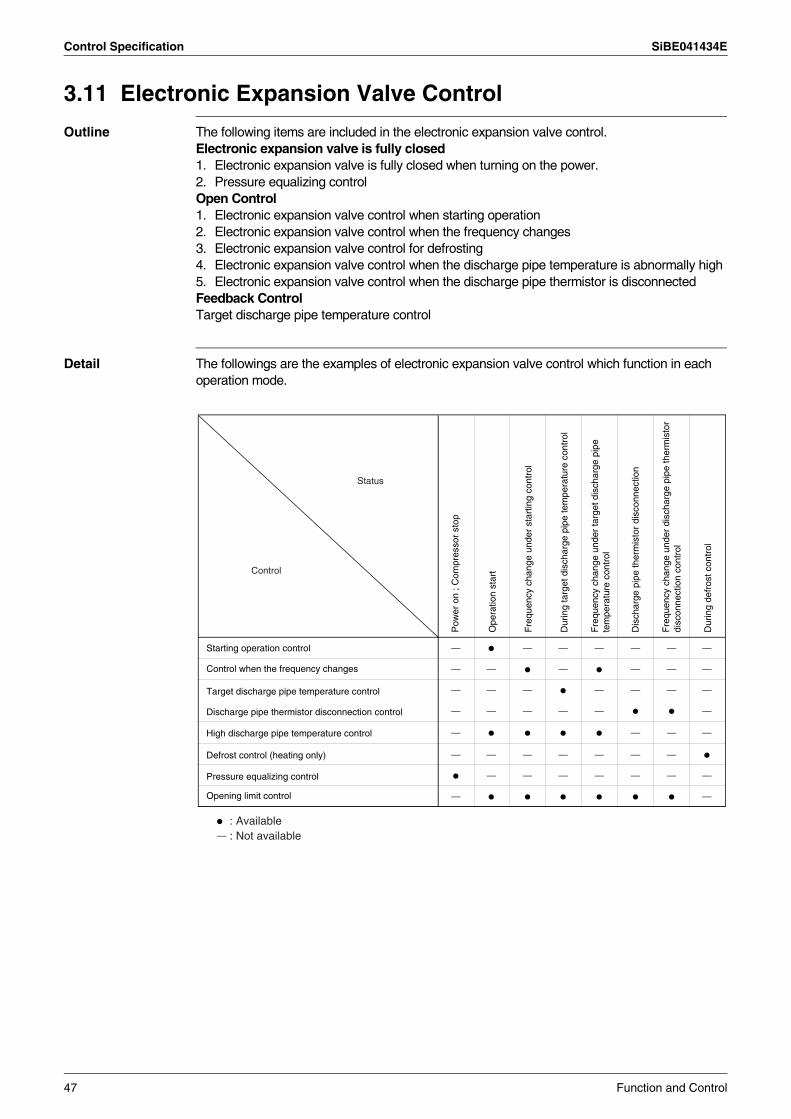
Control Specification SiBE041434E
3.11 Electronic Expansion Valve Control
Outline The following items are included in the electronic expansion valve control.Electronic expansion valve is fully closed1. Electronic expansion valve is fully closed when turning on the power.2. Pressure equalizing controlOpen Control1. Electronic expansion valve control when starting operation2. Electronic expansion valve control when the frequency changes3. Electronic expansion valve control for defrosting4. Electronic expansion valve control when the discharge pipe temperature is abnormally high5. Electronic expansion valve control when the discharge pipe thermistor is disconnectedFeedback ControlTarget discharge pipe temperature control
Detail The followings are the examples of electronic expansion valve control which function in each operation mode.
: Available: Not available
Control
Status
Starting operation control
Control when the frequency changes
Target discharge pipe temperature control
Discharge pipe thermistor disconnection control
High discharge pipe temperature control
Defrost control (heating only)
Pressure equalizing control
Opening limit control
Pow
er o
n ; C
ompr
esso
r st
op
Ope
ratio
n st
art
Fre
quen
cy c
hang
e un
der
star
ting
cont
rol
Dur
ing
targ
et d
isch
arge
pip
e te
mpe
ratu
re c
ontr
ol
Fre
quen
cy c
hang
e un
der
targ
et d
isch
arge
pip
e te
mpe
ratu
re c
ontr
ol
Dis
char
ge p
ipe
ther
mis
tor
disc
onne
ctio
n
Fre
quen
cy c
hang
e un
der
disc
harg
e pi
pe th
erm
isto
r di
scon
nect
ion
cont
rol
Dur
ing
defr
ost c
ontr
ol
47 Function and Control
SiBE041434E Control Specification
3.11.1 Fully Closing with Power ONThe electronic expansion valve is initialized when turning on the power. The opening position is set and the pressure is equalized.
3.11.2 Pressure Equalizing ControlWhen the compressor is stopped, the pressure equalizing control is activated. The electronic expansion valve opens and the pressure is equalized.
3.11.3 Opening Limit ControlThe maximum and minimum opening of the electronic expansion valve are limited.
The electronic expansion valve is fully closed when cooling operation stops, and is opened at a fixed degree during defrosting.
3.11.4 Starting Operation ControlThe electronic expansion valve opening is controlled when the operation starts, thus preventing superheating or liquid compression.
3.11.5 Control when the Frequency ChangesWhen the target discharge pipe temperature control is active, if the target frequency changes to a specified value in a certain time period, the target discharge pipe temperature control is canceled and the target opening of the electronic expansion valve is changed according to the frequency shift.
3.11.6 High Discharge Pipe Temperature ControlWhen the compressor is operating, if the discharge pipe temperature exceeds a certain value, the electronic expansion valve opens and the refrigerant runs to the low pressure side. This procedure lowers the discharge pipe temperature.
20/25/35 class 42/50 class
Maximum opening (pulse) 480 500
Minimum opening (pulse) 32 52
Function and Control 48
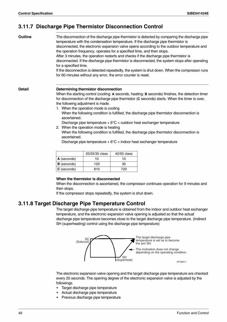
Control Specification SiBE041434E
3.11.7 Discharge Pipe Thermistor Disconnection Control
Outline The disconnection of the discharge pipe thermistor is detected by comparing the discharge pipe temperature with the condensation temperature. If the discharge pipe thermistor is disconnected, the electronic expansion valve opens according to the outdoor temperature and the operation frequency, operates for a specified time, and then stops.After 3 minutes, the operation restarts and checks if the discharge pipe thermistor is disconnected. If the discharge pipe thermistor is disconnected, the system stops after operating for a specified time.If the disconnection is detected repeatedly, the system is shut down. When the compressor runs for 60 minutes without any error, the error counter is reset.
Detail Determining thermistor disconnection When the starting control (cooling: A seconds, heating: B seconds) finishes, the detection timer for disconnection of the discharge pipe thermistor (C seconds) starts. When the timer is over, the following adjustment is made.1. When the operation mode is cooling
When the following condition is fulfilled, the discharge pipe thermistor disconnection is ascertained.Discharge pipe temperature + 6°C < outdoor heat exchanger temperature
2. When the operation mode is heatingWhen the following condition is fulfilled, the discharge pipe thermistor disconnection is ascertained.Discharge pipe temperature + 6°C < indoor heat exchanger temperature
When the thermistor is disconnectedWhen the disconnection is ascertained, the compressor continues operation for 9 minutes and then stops.If the compressor stops repeatedly, the system is shut down.
3.11.8 Target Discharge Pipe Temperature ControlThe target discharge pipe temperature is obtained from the indoor and outdoor heat exchanger temperature, and the electronic expansion valve opening is adjusted so that the actual discharge pipe temperature becomes close to the target discharge pipe temperature. (Indirect SH (superheating) control using the discharge pipe temperature)
The electronic expansion valve opening and the target discharge pipe temperature are checked every 20 seconds. The opening degree of the electronic expansion valve is adjusted by the followings.
Target discharge pipe temperatureActual discharge pipe temperaturePrevious discharge pipe temperature
20/25/35 class 42/50 class
A (seconds) 10 10
B (seconds) 120 30
C (seconds) 810 720
SC (Subcool)
SH (Superheat)
The target discharge pipe temperature is set as to become the aim SH.
The inclination does not change depending on the operating condition.
(R18921)
49 Function and Control
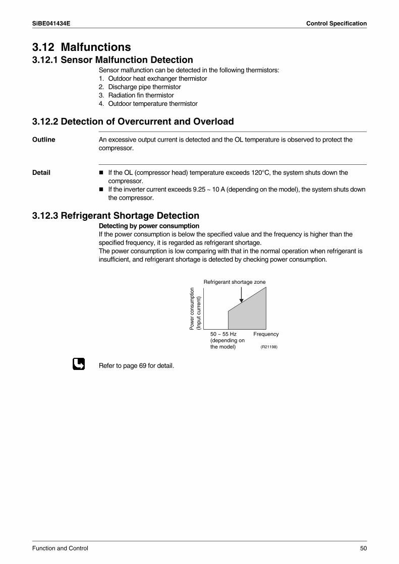
SiBE041434E Control Specification
3.12 Malfunctions3.12.1 Sensor Malfunction Detection
Sensor malfunction can be detected in the following thermistors:1. Outdoor heat exchanger thermistor2. Discharge pipe thermistor3. Radiation fin thermistor4. Outdoor temperature thermistor
3.12.2 Detection of Overcurrent and Overload
Outline An excessive output current is detected and the OL temperature is observed to protect the compressor.
Detail If the OL (compressor head) temperature exceeds 120°C, the system shuts down the compressor.If the inverter current exceeds 9.25 ~ 10 A (depending on the model), the system shuts down the compressor.
3.12.3 Refrigerant Shortage DetectionDetecting by power consumptionIf the power consumption is below the specified value and the frequency is higher than the specified frequency, it is regarded as refrigerant shortage.The power consumption is low comparing with that in the normal operation when refrigerant is insufficient, and refrigerant shortage is detected by checking power consumption.
Refer to page 69 for detail.
Frequency
Refrigerant shortage zone
(R21198)
50 ~ 55 Hz (depending on the model)
Pow
er c
onsu
mpt
ion
(Inp
ut c
urre
nt)
Function and Control 50
SiBE041434E
51 Remote Controller
Part 5Remote Controller
1. 20/25 Class ...........................................................................................522. 35/42/50 Class ......................................................................................54
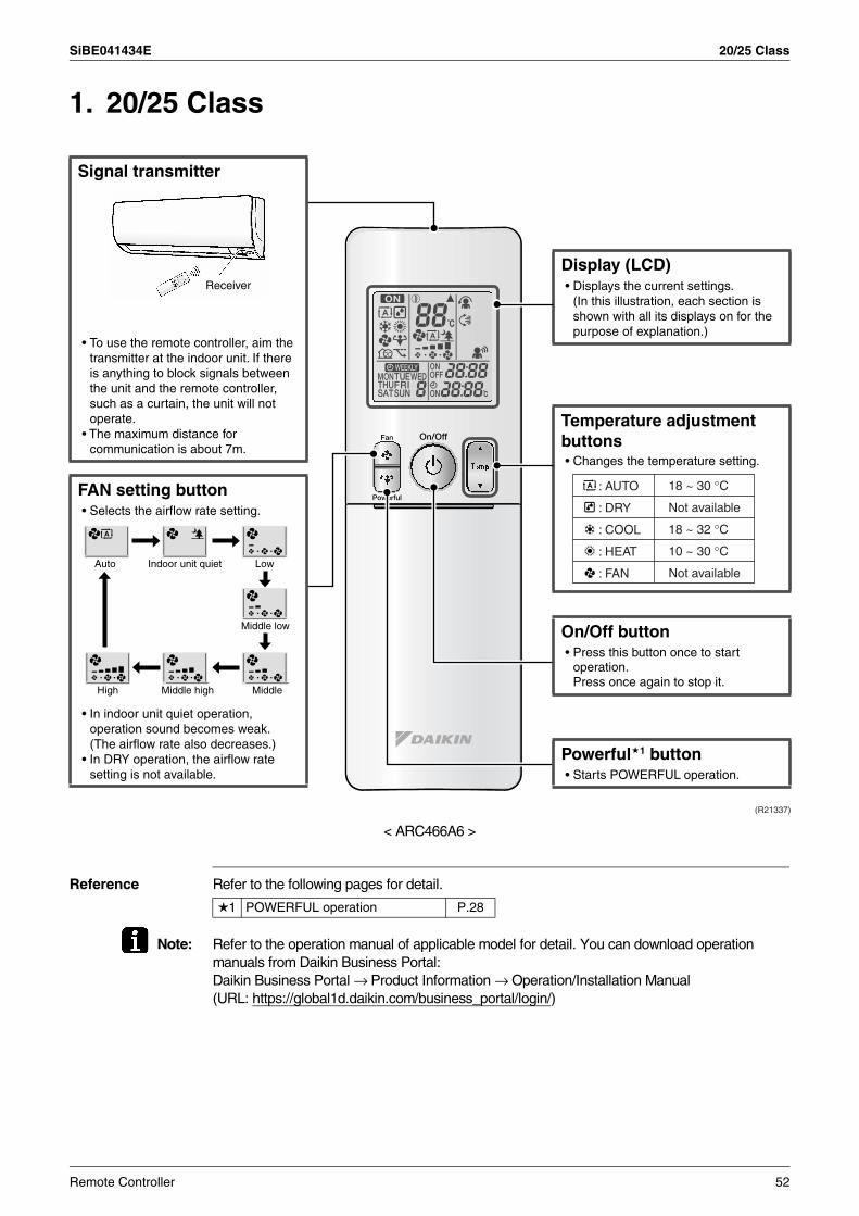
SiBE041434E 20/25 Class
1. 20/25 Class
< ARC466A6 >
Reference Refer to the following pages for detail.
Note: Refer to the operation manual of applicable model for detail. You can download operation manuals from Daikin Business Portal:Daikin Business Portal → Product Information → Operation/Installation Manual(URL: https://global1d.daikin.com/business_portal/login/)
Signal transmitter
Powerful 1 button• Starts POWERFUL operation.
Display (LCD)
• Changes the temperature setting.
On/Off button
Auto Indoor unit quiet Low
Middle low
MiddleMiddle highHigh
• Press this button once to start operation.Press once again to stop it.
Temperature adjustment buttons
: AUTO
: DRY
: COOL
: HEAT
: FAN
18 ~ 30 °C
Not available
18 ~ 32 °C
10 ~ 30 °C
Not available
• Displays the current settings.(In this illustration, each section is shown with all its displays on for the purpose of explanation.)
• To use the remote controller, aim the transmitter at the indoor unit. If there is anything to block signals between the unit and the remote controller, such as a curtain, the unit will not operate.
• The maximum distance for communication is about 7m.
FAN setting button
• In indoor unit quiet operation, operation sound becomes weak. (The airflow rate also decreases.)
• In DRY operation, the airflow rate setting is not available.
• Selects the airflow rate setting.
(R21337)
Receiver
1 POWERFUL operation P.28
Remote Controller 52
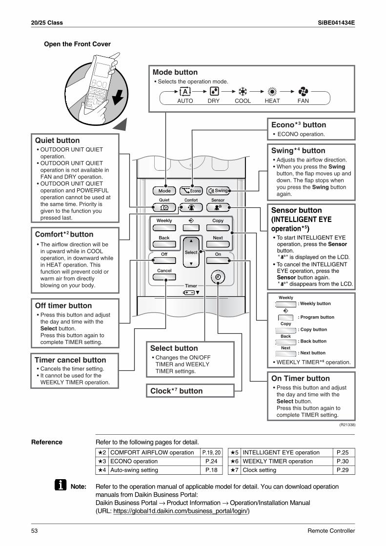
20/25 Class SiBE041434E
Open the Front Cover
Reference Refer to the following pages for detail.
Note: Refer to the operation manual of applicable model for detail. You can download operation manuals from Daikin Business Portal:Daikin Business Portal → Product Information → Operation/Installation Manual(URL: https://global1d.daikin.com/business_portal/login/)
Off timer button
Comfort 2 button
Quiet button
Econo 3 buttonECONO operation. •
Swing 4 button
On Timer button
• WEEKLY TIMER 6 operation.
Clock 7 button
Select button
Mode button• Selects the operation mode.
• OUTDOOR UNIT QUIET operation.
• OUTDOOR UNIT QUIET operation is not available in FAN and DRY operation.
• OUTDOOR UNIT QUIET operation and POWERFUL operation cannot be used at the same time. Priority is given to the function you pressed last.
• The airflow direction will be in upward while in COOL operation, in downward while in HEAT operation. This function will prevent cold or warm air from directly blowing on your body.
• Press this button and adjust the day and time with the Select button.Press this button again to complete TIMER setting.
Timer cancel button• Cancels the timer setting.• It cannot be used for the
WEEKLY TIMER operation.
• Changes the ON/OFF TIMER and WEEKLY TIMER settings.
• Adjusts the airflow direction.• When you press the Swing
button, the flap moves up and down. The flap stops when you press the Swing button again.
• Press this button and adjust the day and time with the Select button.Press this button again to complete TIMER setting.
(R21338)
Sensor button(INTELLIGENT EYE operation 5)• To start INTELLIGENT EYE
operation, press the Sensor button.
" " is displayed on the LCD.• To cancel the INTELLIGENT
EYE operation, press the Sensor button again.
" " disappears from the LCD.
: Weekly button
: Program button
: Copy button
: Back button
: Next button
Weekly
Copy
Back
Next
AUTO DRY COOL HEAT FAN
2 COMFORT AIRFLOW operation P.19, 20 5 INTELLIGENT EYE operation P.25
3 ECONO operation P.24 6 WEEKLY TIMER operation P.30
4 Auto-swing setting P.18 7 Clock setting P.29
53 Remote Controller
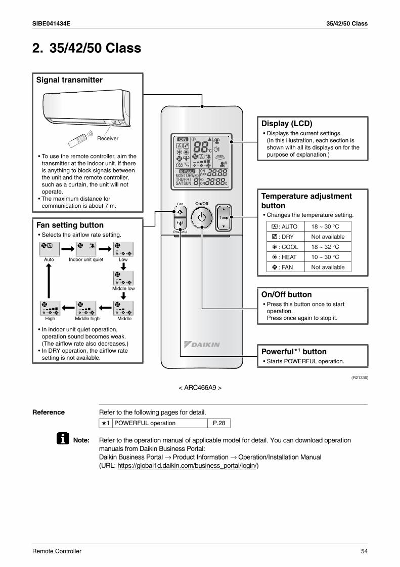
SiBE041434E 35/42/50 Class
2. 35/42/50 Class
< ARC466A9 >
Reference Refer to the following pages for detail.
Note: Refer to the operation manual of applicable model for detail. You can download operation manuals from Daikin Business Portal:Daikin Business Portal → Product Information → Operation/Installation Manual(URL: https://global1d.daikin.com/business_portal/login/)
Signal transmitter
Powerful 1 button• Starts POWERFUL operation.
Display (LCD)
• Changes the temperature setting.
On/Off button
Auto Indoor unit quiet Low
Middle low
MiddleMiddle highHigh
• Press this button once to start operation.Press once again to stop it.
Temperature adjustment button
: AUTO
: DRY
: COOL
: HEAT
: FAN
18 ~ 30 °C
Not available
18 ~ 32 °C
10 ~ 30 °C
Not available
• Displays the current settings.(In this illustration, each section is shown with all its displays on for the purpose of explanation.)• To use the remote controller, aim the
transmitter at the indoor unit. If there is anything to block signals between the unit and the remote controller, such as a curtain, the unit will not operate.
• The maximum distance for communication is about 7 m.
Fan setting button
• In indoor unit quiet operation, operation sound becomes weak. (The airflow rate also decreases.)
• In DRY operation, the airflow rate setting is not available.
• Selects the airflow rate setting.
(R21336)
Receiver
1 POWERFUL operation P.28
Remote Controller 54
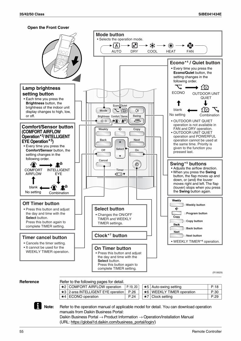
35/42/50 Class SiBE041434E
Open the Front Cover
Reference Refer to the following pages for detail.
Note: Refer to the operation manual of applicable model for detail. You can download operation manuals from Daikin Business Portal:Daikin Business Portal → Product Information → Operation/Installation Manual(URL: https://global1d.daikin.com/business_portal/login/)
Off Timer button
Swing 5 buttons
On Timer button
• WEEKLY TIMER 6 operation.
Clock 7 button
Select button
Mode button• Selects the operation mode.
• Press this button and adjust the day and time with the Select button.Press this button again to complete TIMER setting.
Timer cancel button• Cancels the timer setting.• It cannot be used for the
WEEKLY TIMER operation.
• Changes the ON/OFF TIMER and WEEKLY TIMER settings.
• Adjusts the airflow direction.• When you press the Swing
button, the flap moves up and down, or (and) the louver moves right and left. The flap (louver) stops when you press the Swing button again.
• Press this button and adjust the day and time with the Select button.Press this button again to complete TIMER setting.
(R19929)
: Weekly button
: Program button
: Copy button
: Back button
: Next button
Lamp brightness setting button
• OUTDOOR UNIT QUIET operation is not available in FAN and DRY operation.
• OUTDOOR UNIT QUIET operation and POWERFUL operation cannot be used at the same time. Priority is given to the function you pressed last.
Econo 4 / Quiet button
blankNo setting Combination
Comfort/Sensor button(COMFORT AIRFLOW Operation 2/ INTELLIGENT EYE Operation 3)
INTELLIGENT EYE
COMFORT AIRFLOW
• Every time you press the Comfort/Sensor button, the setting changes in the following order.
ECONO
blankNo setting Combination
• Every time you press the Econo/Quiet button, the setting changes in the following order.
OUTDOOR UNIT QUIET
AUTO DRY COOL HEAT FAN
• Each time you press the Brightness button, the brightness of the indoor unit display changes to high, low, or off.
2 COMFORT AIRFLOW operation P.19, 20 5 Auto-swing setting P.183 2-area INTELLIGENT EYE operation P.26 6 WEEKLY TIMER operation P.304 ECONO operation P.24 7 Clock setting P.29
55 Remote Controller
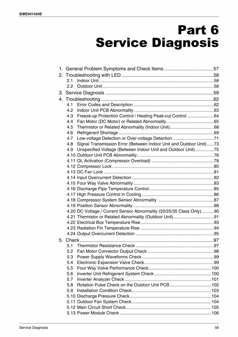
SiBE041434E
Service Diagnosis 56
Part 6Service Diagnosis
1. General Problem Symptoms and Check Items .....................................572. Troubleshooting with LED .....................................................................58
2.1 Indoor Unit..............................................................................................582.2 Outdoor Unit ...........................................................................................58
3. Service Diagnosis .................................................................................594. Troubleshooting ....................................................................................62
4.1 Error Codes and Description ..................................................................624.2 Indoor Unit PCB Abnormality .................................................................634.3 Freeze-up Protection Control / Heating Peak-cut Control ......................644.4 Fan Motor (DC Motor) or Related Abnormality.......................................654.5 Thermistor or Related Abnormality (Indoor Unit)....................................684.6 Refrigerant Shortage ..............................................................................694.7 Low-voltage Detection or Over-voltage Detection..................................714.8 Signal Transmission Error (Between Indoor Unit and Outdoor Unit)......734.9 Unspecified Voltage (Between Indoor Unit and Outdoor Unit) ...............754.10 Outdoor Unit PCB Abnormality...............................................................764.11 OL Activation (Compressor Overload) ...................................................784.12 Compressor Lock ...................................................................................804.13 DC Fan Lock ..........................................................................................814.14 Input Overcurrent Detection ...................................................................824.15 Four Way Valve Abnormality..................................................................834.16 Discharge Pipe Temperature Control.....................................................854.17 High Pressure Control in Cooling ...........................................................864.18 Compressor System Sensor Abnormality ..............................................874.19 Position Sensor Abnormality ..................................................................884.20 DC Voltage / Current Sensor Abnormality (20/25/35 Class Only)..........904.21 Thermistor or Related Abnormality (Outdoor Unit) .................................914.22 Electrical Box Temperature Rise............................................................934.23 Radiation Fin Temperature Rise ............................................................944.24 Output Overcurrent Detection ................................................................95
5. Check ....................................................................................................975.1 Thermistor Resistance Check ................................................................975.2 Fan Motor Connector Output Check ......................................................985.3 Power Supply Waveforms Check...........................................................995.4 Electronic Expansion Valve Check.........................................................995.5 Four Way Valve Performance Check ...................................................1005.6 Inverter Unit Refrigerant System Check...............................................1005.7 Inverter Analyzer Check .......................................................................1015.8 Rotation Pulse Check on the Outdoor Unit PCB ..................................1025.9 Installation Condition Check.................................................................1035.10 Discharge Pressure Check...................................................................1045.11 Outdoor Fan System Check .................................................................1045.12 Main Circuit Short Check......................................................................1055.13 Power Module Check ...........................................................................106
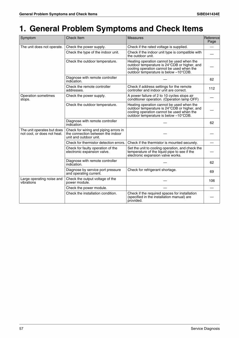
General Problem Symptoms and Check Items SiBE041434E
1. General Problem Symptoms and Check ItemsSymptom Check Item Measures Reference
Page
The unit does not operate. Check the power supply. Check if the rated voltage is supplied. —
Check the type of the indoor unit. Check if the indoor unit type is compatible with the outdoor unit. —
Check the outdoor temperature. Heating operation cannot be used when the outdoor temperature is 24°CDB or higher, and cooling operation cannot be used when the outdoor temperature is below –10°CDB.
—
Diagnose with remote controller indication. — 62
Check the remote controller addresses.
Check if address settings for the remote controller and indoor unit are correct. 112
Operation sometimes stops.
Check the power supply. A power failure of 2 to 10 cycles stops air conditioner operation. (Operation lamp OFF) —
Check the outdoor temperature. Heating operation cannot be used when the outdoor temperature is 24°CDB or higher, and cooling operation cannot be used when the outdoor temperature is below –10°CDB.
—
Diagnose with remote controller indication. — 62
The unit operates but does not cool, or does not heat.
Check for wiring and piping errors in the connection between the indoor unit and outdoor unit.
— —
Check for thermistor detection errors. Check if the thermistor is mounted securely. —
Check for faulty operation of the electronic expansion valve.
Set the unit to cooling operation, and check the temperature of the liquid pipe to see if the electronic expansion valve works.
—
Diagnose with remote controller indication. — 62
Diagnose by service port pressure and operating current.
Check for refrigerant shortage. 69
Large operating noise and vibrations
Check the output voltage of the power module. — 106
Check the power module. — —
Check the installation condition. Check if the required spaces for installation (specified in the installation manual) are provided.
—
57 Service Diagnosis
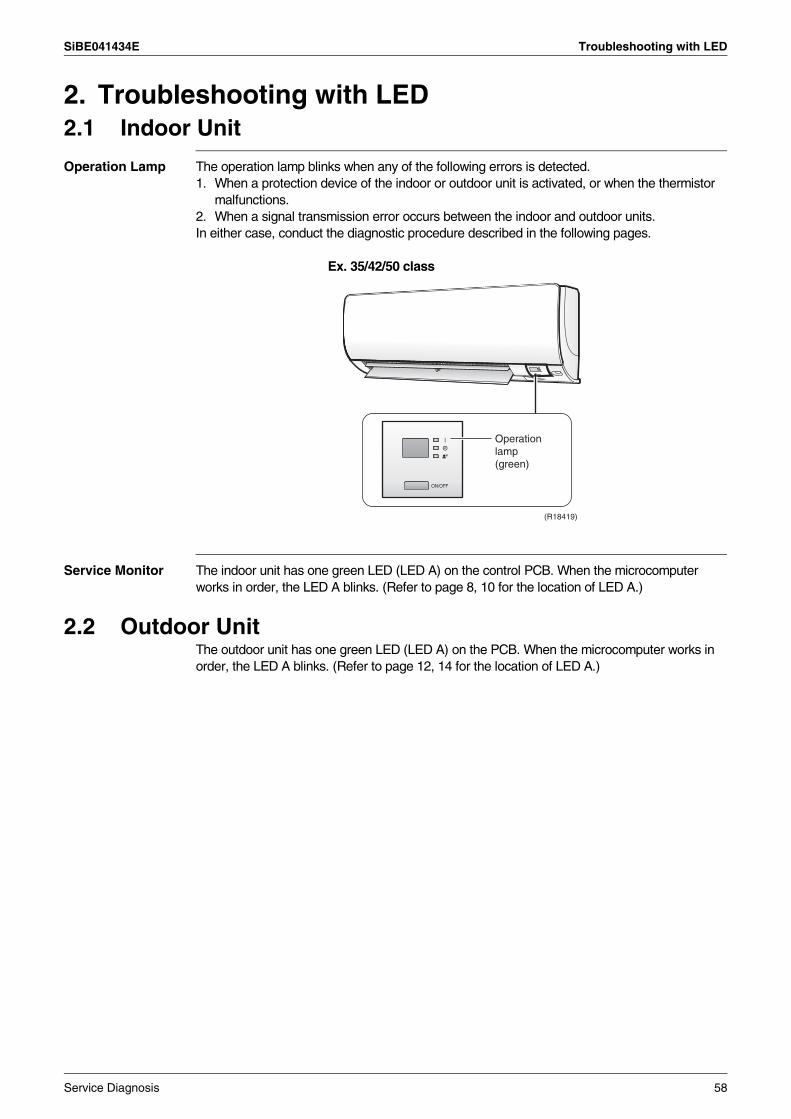
SiBE041434E Troubleshooting with LED
2. Troubleshooting with LED2.1 Indoor Unit
Operation Lamp The operation lamp blinks when any of the following errors is detected.1. When a protection device of the indoor or outdoor unit is activated, or when the thermistor
malfunctions.2. When a signal transmission error occurs between the indoor and outdoor units.In either case, conduct the diagnostic procedure described in the following pages.
Ex. 35/42/50 class
Service Monitor The indoor unit has one green LED (LED A) on the control PCB. When the microcomputer works in order, the LED A blinks. (Refer to page 8, 10 for the location of LED A.)
2.2 Outdoor UnitThe outdoor unit has one green LED (LED A) on the PCB. When the microcomputer works in order, the LED A blinks. (Refer to page 12, 14 for the location of LED A.)
(R18419)
Operation lamp (green)
Service Diagnosis 58
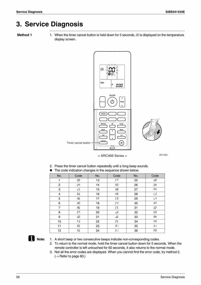
Service Diagnosis SiBE041434E
3. Service Diagnosis Method 1 1. When the timer cancel button is held down for 5 seconds, 00 is displayed on the temperature
display screen.
2. Press the timer cancel button repeatedly until a long beep sounds.The code indication changes in the sequence shown below.
Note: 1. A short beep or two consecutive beeps indicate non-corresponding codes.2. To return to the normal mode, hold the timer cancel button down for 5 seconds. When the
remote controller is left untouched for 60 seconds, it also returns to the normal mode.3. Not all the error codes are displayed. When you cannot find the error code, try method 2.
(→ Refer to page 60.)
No. Code No. Code No. Code
1 00 13 C7 25 UA
2 U4 14 A3 26 UH
3 L5 15 H8 27 P4
4 E6 16 H9 28 L3
5 H6 17 C9 29 L4
6 H0 18 C4 30 H7
7 A6 19 C5 31 U2
8 E7 20 J3 32 EA
9 U0 21 J6 33 AH
10 F3 22 E5 34 FA
11 A5 23 A1 35 H1
12 F6 24 E1 36 P9
(R21282)< ARC466 Series >
Timer cancel button
59 Service Diagnosis
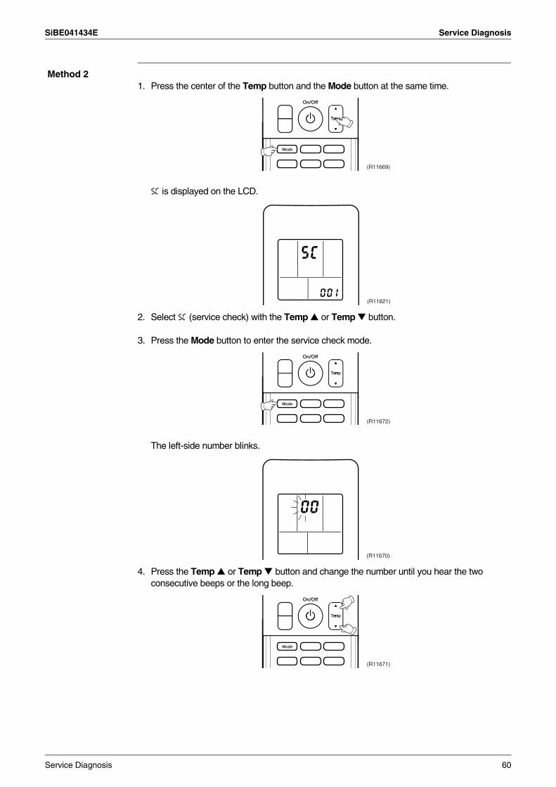
SiBE041434E Service Diagnosis
Method 21. Press the center of the Temp button and the Mode button at the same time.
5C is displayed on the LCD.
2. Select 5C (service check) with the Temp or Temp button.
3. Press the Mode button to enter the service check mode.
The left-side number blinks.
4. Press the Temp or Temp button and change the number until you hear the two consecutive beeps or the long beep.
(R11669)
(R11821)
(R11672)
(R11670)
(R11671)
Service Diagnosis 60
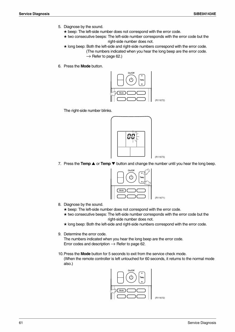
Service Diagnosis SiBE041434E
5. Diagnose by the sound. beep: The left-side number does not correspond with the error code. two consecutive beeps: The left-side number corresponds with the error code but the
right-side number does not. long beep: Both the left-side and right-side numbers correspond with the error code.
(The numbers indicated when you hear the long beep are the error code.→ Refer to page 62.)
6. Press the Mode button.
The right-side number blinks.
7. Press the Temp or Temp button and change the number until you hear the long beep.
8. Diagnose by the sound. beep: The left-side number does not correspond with the error code. two consecutive beeps: The left-side number corresponds with the error code but the
right-side number does not. long beep: Both the left-side and right-side numbers correspond with the error code.
9. Determine the error code.The numbers indicated when you hear the long beep are the error code.Error codes and description → Refer to page 62.
10.Press the Mode button for 5 seconds to exit from the service check mode.(When the remote controller is left untouched for 60 seconds, it returns to the normal mode also.)
(R11672)
(R11673)
(R11671)
(R11672)
61 Service Diagnosis
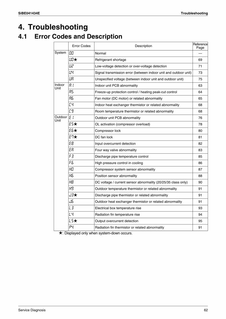
SiBE041434E Troubleshooting
4. Troubleshooting4.1 Error Codes and Description
: Displayed only when system-down occurs.
Error Codes Description ReferencePage
System 00 Normal —
U0 Refrigerant shortage 69
U2 Low-voltage detection or over-voltage detection 71
U4 Signal transmission error (between indoor unit and outdoor unit) 73
UA Unspecified voltage (between indoor unit and outdoor unit) 75
IndoorUnit
A1 Indoor unit PCB abnormality 63
A5 Freeze-up protection control / heating peak-cut control 64
A6 Fan motor (DC motor) or related abnormality 65
C4 Indoor heat exchanger thermistor or related abnormality 68
C9 Room temperature thermistor or related abnormality 68
OutdoorUnit
E1 Outdoor unit PCB abnormality 76
E5 OL activation (compressor overload) 78
E6 Compressor lock 80
E7 DC fan lock 81
E8 Input overcurrent detection 82
EA Four way valve abnormality 83
F3 Discharge pipe temperature control 85
F6 High pressure control in cooling 86
H0 Compressor system sensor abnormality 87
H6 Position sensor abnormality 88
H8 DC voltage / current sensor abnormality (20/25/35 class only) 90
H9 Outdoor temperature thermistor or related abnormality 91
J3 Discharge pipe thermistor or related abnormality 91
J6 Outdoor heat exchanger thermistor or related abnormality 91
L3 Electrical box temperature rise 93
L4 Radiation fin temperature rise 94
L5 Output overcurrent detection 95
P4 Radiation fin thermistor or related abnormality 91
Service Diagnosis 62
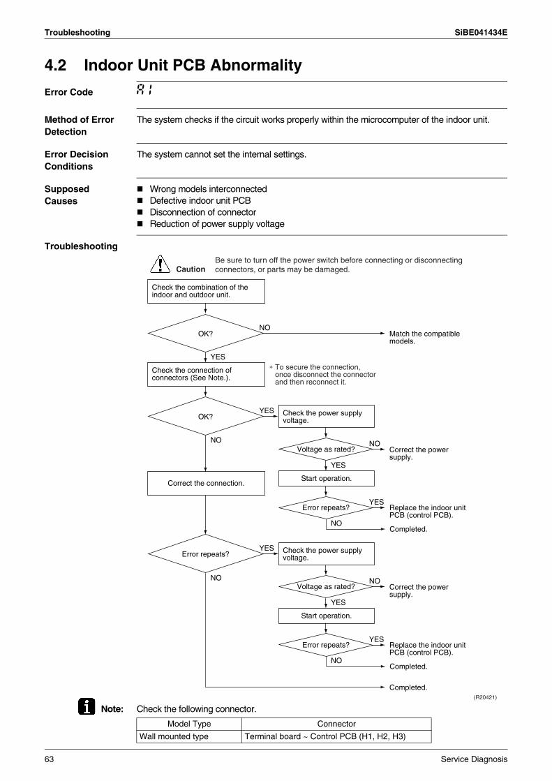
Troubleshooting SiBE041434E
4.2 Indoor Unit PCB Abnormality
Error Code A1
Method of Error Detection
The system checks if the circuit works properly within the microcomputer of the indoor unit.
Error Decision Conditions
The system cannot set the internal settings.
Supposed Causes
Wrong models interconnectedDefective indoor unit PCBDisconnection of connectorReduction of power supply voltage
Troubleshooting
Note: Check the following connector.
Check the combination of the indoor and outdoor unit.
OK?
Check the connection of connectors (See Note.).
Correct the connection.
OK? Check the power supply voltage.
Start operation.
Voltage as rated?
Error repeats?
Check the power supply voltage.
Start operation.
Voltage as rated?
Error repeats?
Error repeats?
YES
NO
NO
YES
NO
NO
YES
(R20421)
Caution
∗ To secure the connection, once disconnect the connector and then reconnect it.
YES
NO
YES
NO
YES
NO
YES
Match the compatible models.
Correct the power supply.
Replace the indoor unit PCB (control PCB).
Completed.
Completed.
Correct the power supply.
Replace the indoor unit PCB (control PCB).
Completed.
Be sure to turn off the power switch before connecting or disconnecting connectors, or parts may be damaged.
Model Type Connector
Wall mounted type Terminal board ~ Control PCB (H1, H2, H3)
63 Service Diagnosis
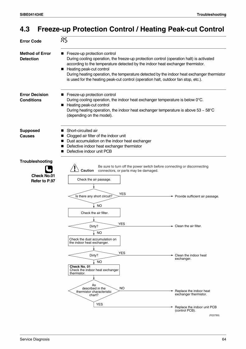
SiBE041434E Troubleshooting
4.3 Freeze-up Protection Control / Heating Peak-cut Control
Error Code A5
Method of Error Detection
Freeze-up protection controlDuring cooling operation, the freeze-up protection control (operation halt) is activated according to the temperature detected by the indoor heat exchanger thermistor.Heating peak-cut controlDuring heating operation, the temperature detected by the indoor heat exchanger thermistor is used for the heating peak-cut control (operation halt, outdoor fan stop, etc.).
Error Decision Conditions
Freeze-up protection controlDuring cooling operation, the indoor heat exchanger temperature is below 0°C.Heating peak-cut controlDuring heating operation, the indoor heat exchanger temperature is above 53 ~ 58°C (depending on the model).
Supposed Causes
Short-circuited airClogged air filter of the indoor unitDust accumulation on the indoor heat exchangerDefective indoor heat exchanger thermistorDefective indoor unit PCB
Troubleshooting
Check No.01Refer to P.97
NO
NO
NO
Check No. 01Check the indoor heat exchanger thermistor.
YES
YES
(R20789)
YES
YES
NO
Caution
Provide sufficient air passage.
Clean the air filter.
Clean the indoor heat exchanger.
Replace the indoor unit PCB (control PCB).
Replace the indoor heat exchanger thermistor.
As described in the
thermistor characteristic chart?
Check the air filter.
Check the dust accumulation on the indoor heat exchanger.
Is there any short circuit?
Dirty?
Dirty?
Check the air passage.
Be sure to turn off the power switch before connecting or disconnecting connectors, or parts may be damaged.
Service Diagnosis 64
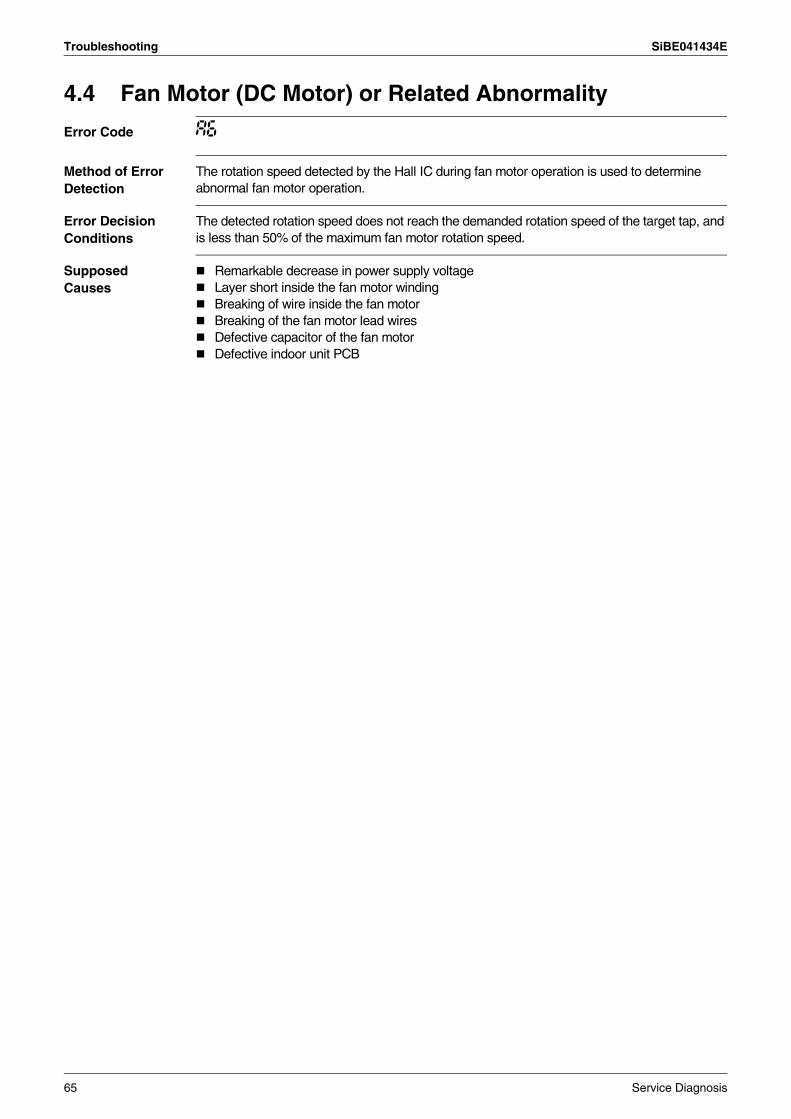
Troubleshooting SiBE041434E
4.4 Fan Motor (DC Motor) or Related Abnormality
Error Code A6
Method of Error Detection
The rotation speed detected by the Hall IC during fan motor operation is used to determine abnormal fan motor operation.
Error Decision Conditions
The detected rotation speed does not reach the demanded rotation speed of the target tap, and is less than 50% of the maximum fan motor rotation speed.
Supposed Causes
Remarkable decrease in power supply voltageLayer short inside the fan motor windingBreaking of wire inside the fan motorBreaking of the fan motor lead wiresDefective capacitor of the fan motorDefective indoor unit PCB
65 Service Diagnosis
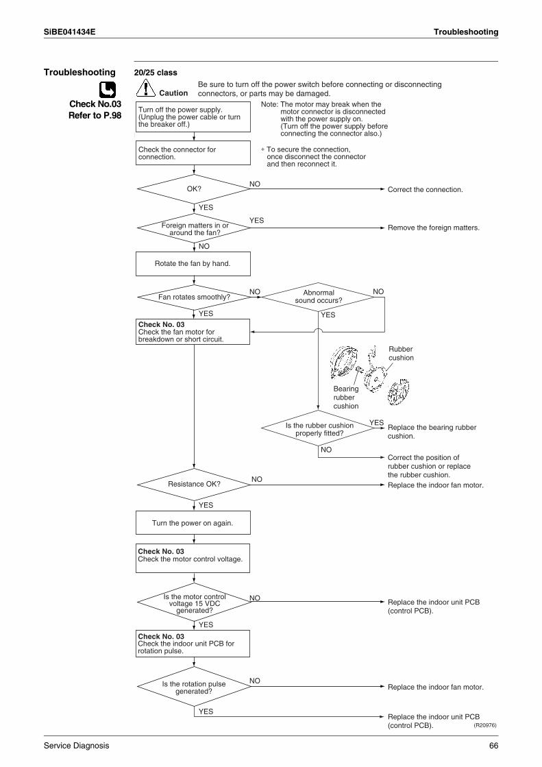
SiBE041434E Troubleshooting
Troubleshooting 20/25 class
Check No.03Refer to P.98
Caution
OK?NO
YES
YES
NO
Check No. 03
Check No. 03
Check No. 03
NO
YES
YES
YES
NO
NO
YES
NO
Be sure to turn off the power switch before connecting or disconnecting connectors, or parts may be damaged.
Check the connector for connection.
Note: The motor may break when the motor connector is disconnected with the power supply on.(Turn off the power supply before connecting the connector also.)
∗ To secure the connection, once disconnect the connector and then reconnect it.
Foreign matters in or around the fan?
Is the rotation pulse generated?
Rotate the fan by hand.
Turn the power on again.
Check the fan motor for breakdown or short circuit.
Check the motor control voltage.
Check the indoor unit PCB for rotation pulse.
Fan rotates smoothly?
Resistance OK?
Is the motor control voltage 15 VDC
generated?
Correct the connection.
Remove the foreign matters.
Replace the indoor fan motor.
Replace the indoor unit PCB (control PCB).
Replace the indoor fan motor.
Replace the indoor unit PCB (control PCB).
Turn off the power supply. (Unplug the power cable or turn the breaker off.)
(R20976)
YES
NO
NO
Abnormal sound occurs?
Is the rubber cushion properly fitted?
YES
Correct the position of rubber cushion or replace the rubber cushion.
Replace the bearing rubber cushion.
Rubber cushion
Bearing rubber cushion
Service Diagnosis 66
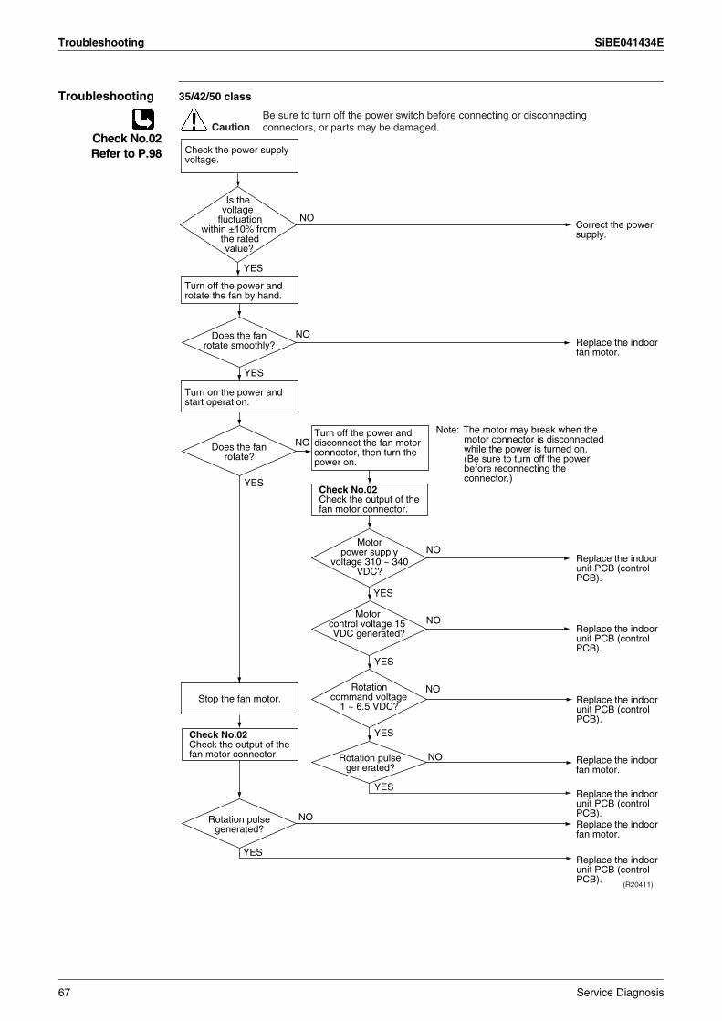
Troubleshooting SiBE041434E
Troubleshooting 35/42/50 class
Check No.02Refer to P.98
CautionBe sure to turn off the power switch before connecting or disconnecting connectors, or parts may be damaged.
Correct the power supply.
NO
Check the power supply voltage.
Turn off the power and disconnect the fan motor connector, then turn the power on.
Check No.02Check the output of the fan motor connector.
YES
YES
NO
YES
YES
NO
NO
NO
Note: The motor may break when the motor connector is disconnected while the power is turned on.(Be sure to turn off the power before reconnecting the connector.)
Replace the indoor fan motor.
Replace the indoor unit PCB (control PCB).
Replace the indoor unit PCB (control PCB).
Does the fan rotate smoothly?
Does the fan rotate?
Motor power supply
voltage 310 ~ 340 VDC?
Turn off the power and rotate the fan by hand.
Turn on the power and start operation.
Check No.02Check the output of the fan motor connector.
(R20411)
YES
NO
YES
NO
YES
NOReplace the indoor fan motor.
Replace the indoor unit PCB (control PCB).
Replace the indoor unit PCB (control PCB).
Replace the indoor unit PCB (control PCB).
Replace the indoor fan motor.
Rotation pulse generated?
Stop the fan motor.
YES
Is the voltage
fluctuation within ±10% from
the rated value?
Motor control voltage 15 VDC generated?
Rotation command voltage
1 ~ 6.5 VDC?
Rotation pulse generated?
67 Service Diagnosis
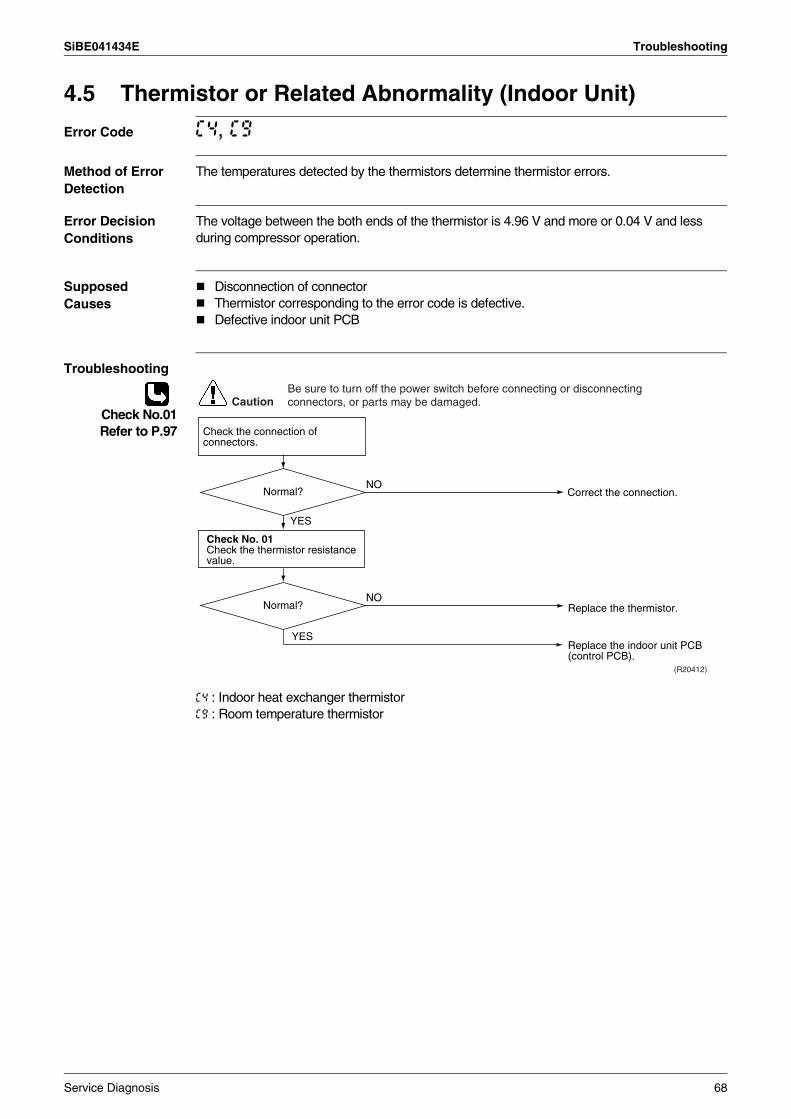
SiBE041434E Troubleshooting
4.5 Thermistor or Related Abnormality (Indoor Unit)
Error Code C4, C9
Method of Error Detection
The temperatures detected by the thermistors determine thermistor errors.
Error Decision Conditions
The voltage between the both ends of the thermistor is 4.96 V and more or 0.04 V and less during compressor operation.
Supposed Causes
Disconnection of connectorThermistor corresponding to the error code is defective.Defective indoor unit PCB
Troubleshooting
Check No.01Refer to P.97
C4 : Indoor heat exchanger thermistorC9 : Room temperature thermistor
YES
(R20412)
NO
Check No. 01Check the thermistor resistance value.
YES
NO
Caution
Correct the connection.
Replace the thermistor.
Replace the indoor unit PCB (control PCB).
Normal?
Normal?
Check the connection of connectors.
Be sure to turn off the power switch before connecting or disconnecting connectors, or parts may be damaged.
Service Diagnosis 68
Troubleshooting SiBE041434E
4.6 Refrigerant Shortage
Error Code U0
Method of Error Detection
Refrigerant shortage is detected by checking the input current value and the compressor running frequency. If the refrigerant is short, the input current is lower than the normal value.
Error Decision Conditions
The following conditions continue for 7 minutes.
Input current × input voltage ≤ A × output frequency + BOutput frequency > C
If the error repeats, the system is shut down.Reset condition: Continuous run for about 60 minutes without any other error
Supposed Causes
Disconnection of the discharge pipe thermistor, indoor or outdoor heat exchanger thermistor, room or outdoor temperature thermistorClosed stop valveRefrigerant shortage (refrigerant leakage)Poor compression performance of compressorDefective electronic expansion valve
A (constant) B (W) C (Hz)20/25/35 class 640/256 0 55
42/50 class 2813/256 50 50
69 Service Diagnosis
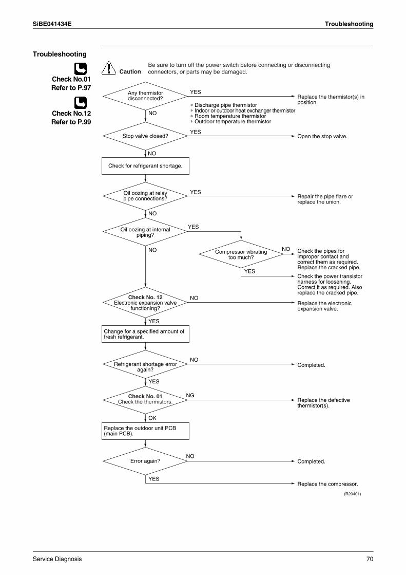
SiBE041434E Troubleshooting
Troubleshooting
Check No.01Refer to P.97
Check No.12Refer to P.99
(R20401)
Caution
YES
NG
NO
NO
YES
YES
YES
NO
NO
YES
YES
NO
YES
NO
NO
∗ Discharge pipe thermistor∗ Indoor or outdoor heat exchanger thermistor∗ Room temperature thermistor∗ Outdoor temperature thermistor
Check for refrigerant shortage.
Change for a specified amount of fresh refrigerant.
Check No. 12Electronic expansion valve
functioning?
Replace the thermistor(s) in position.
Open the stop valve.
Repair the pipe flare or replace the union.
Check the pipes for improper contact and correct them as required. Replace the cracked pipe.
Check the power transistor harness for loosening.Correct it as required. Also replace the cracked pipe.
Replace the electronic expansion valve.
Replace the defective thermistor(s).
Completed.Refrigerant shortage error again?
Oil oozing at internal piping?
Stop valve closed?
Compressor vibrating too much?
Oil oozing at relay pipe connections?
Any thermistor disconnected?
Check No. 01Check the thermistors.
Be sure to turn off the power switch before connecting or disconnecting connectors, or parts may be damaged.
OK
YES
NO
Replace the outdoor unit PCB (main PCB).
Replace the compressor.
Completed.Error again?
Service Diagnosis 70
Troubleshooting SiBE041434E
4.7 Low-voltage Detection or Over-voltage Detection
Error Code U2
Method of Error Detection
Indoor Unit
The zero-cross detection of the power supply is evaluated by the indoor unit PCB.
Outdoor Unit
Low-voltage detection:An abnormal voltage drop is detected by the DC voltage detection circuit.
Over-voltage detection:An abnormal voltage rise is detected by the over-voltage detection circuit.
Error Decision Conditions
Indoor Unit
There is no zero-cross detection in approximately 10 seconds.
Outdoor Unit
Low-voltage detection: The voltage detected by the DC voltage detection circuit is below 150 ~ 180 V (depending on the model).The compressor stops if the error occurs, and restarts automatically after 3-minute standby.
Over-voltage detection:An over-voltage signal is fed from the over-voltage detection circuit to the microcomputer.The compressor stops if the error occurs, and restarts automatically after 3-minute standby.
Supposed Causes
Power supply voltage is not as specified.Defective DC voltage detection circuitDefective over-voltage detection circuitDefective PAM control partDisconnection of compressor harnessShort circuit inside the fan motor windingNoiseMomentary drop of voltageMomentary power failureDefective outdoor unit PCBDefective indoor unit PCB
71 Service Diagnosis
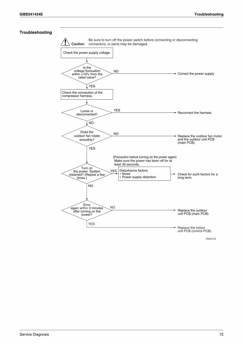
SiBE041434E Troubleshooting
Troubleshooting
Correct the power supply.
Replace the outdoor unit PCB (main PCB).
Check for such factors for a long term.
(R20413)
CautionBe sure to turn off the power switch before connecting or disconnecting connectors, or parts may be damaged.
NO
NO
YES
YES
NO
YES
YESReconnect the harness.
Check the power supply voltage.
Check the connection of the compressor harness.
Disturbance factors∗ Noise∗ Power supply distortion
(Precaution before turning on the power again) Make sure the power has been off for at least 30 seconds.
Replace the indoor unit PCB (control PCB).
Turn on the power. System
restarted? (Repeat a few times.)
Error again within 3 minutes
after turning on the power?
Loose or disconnected?
NO
YES
NOReplace the outdoor fan motor and the outdoor unit PCB (main PCB).
Does the outdoor fan rotate
smoothly?
Is the voltage fluctuation
within ±10% from the rated value?
Service Diagnosis 72
Troubleshooting SiBE041434E
4.8 Signal Transmission Error (Between Indoor Unit and Outdoor Unit)
Error Code U4
Method of Error Detection
The data received from the outdoor unit in signal transmission is checked whether it is normal.
Error Decision Conditions
The data sent from the outdoor unit cannot be received normally, or the content of the data is abnormal.
Supposed Causes
Reduction of power supply voltageWiring errorBreaking of the connecting wires between the indoor and outdoor units (wire No. 3)Defective outdoor unit PCBShort circuit inside the fan motor windingDefective indoor unit PCBDisturbed power supply waveform
73 Service Diagnosis
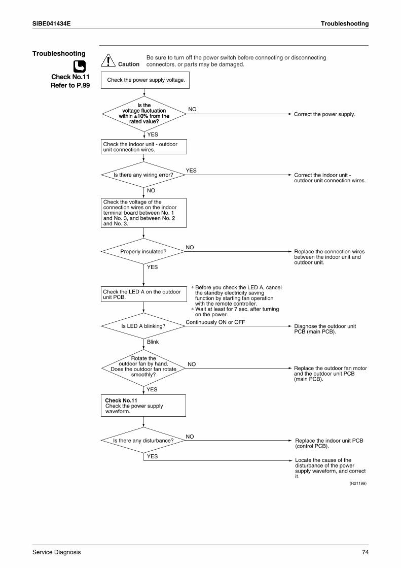
SiBE041434E Troubleshooting
Troubleshooting
Check No.11Refer to P.99
Check No.11Check the power supply waveform.
Check the voltage of the connection wires on the indoor terminal board between No. 1 and No. 3, and between No. 2 and No. 3.
YES
Blink
Replace the indoor unit PCB (control PCB).
Locate the cause of the disturbance of the power supply waveform, and correct it.
NO
(R21199)
Continuously ON or OFF
NO
YES
YES
NO
Caution
Correct the indoor unit - outdoor unit connection wires.
Diagnose the outdoor unit PCB (main PCB).
Replace the connection wires between the indoor unit and outdoor unit.
Is LED A blinking?
Properly insulated?
Is there any disturbance?
Is there any wiring error?
Check the indoor unit - outdoor unit connection wires.
Check the LED A on the outdoor unit PCB.
Be sure to turn off the power switch before connecting or disconnecting connectors, or parts may be damaged.
∗ Before you check the LED A, cancel the standby electricity saving function by starting fan operation with the remote controller.
∗ Wait at least for 7 sec. after turning on the power.
NO
YES
Check the power supply voltage.
Correct the power supply.
YES
NOReplace the outdoor fan motor and the outdoor unit PCB (main PCB).
Rotate the outdoor fan by hand.
Does the outdoor fan rotate smoothly?
Is the voltage fluctuation
within ±10% from the rated value?
Is the voltage fluctuation
within ±10% from the rated value?
Service Diagnosis 74
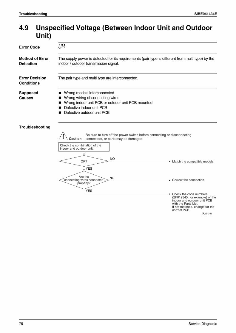
Troubleshooting SiBE041434E
4.9 Unspecified Voltage (Between Indoor Unit and Outdoor Unit)
Error Code UA
Method of Error Detection
The supply power is detected for its requirements (pair type is different from multi type) by the indoor / outdoor transmission signal.
Error Decision Conditions
The pair type and multi type are interconnected.
Supposed Causes
Wrong models interconnectedWrong wiring of connecting wiresWrong indoor unit PCB or outdoor unit PCB mountedDefective indoor unit PCBDefective outdoor unit PCB
Troubleshooting
(R20435)
Caution
NO
YES
YES
NO
Match the compatible models.OK?
Correct the connection.
Check the code numbers (2P012345, for example) of the indoor and outdoor unit PCB with the Parts List.If not matched, change for the correct PCB.
Are the connecting wires connected
properly?
Check the combination of the indoor and outdoor unit.
Be sure to turn off the power switch before connecting or disconnecting connectors, or parts may be damaged.
75 Service Diagnosis
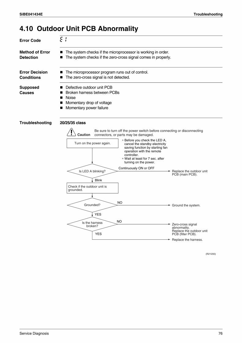
SiBE041434E Troubleshooting
4.10 Outdoor Unit PCB Abnormality
Error Code E1
Method of Error Detection
The system checks if the microprocessor is working in order.The system checks if the zero-cross signal comes in properly.
Error Decision Conditions
The microprocessor program runs out of control.The zero-cross signal is not detected.
Supposed Causes
Defective outdoor unit PCBBroken harness between PCBsNoiseMomentary drop of voltageMomentary power failure
Troubleshooting 20/25/35 class
CautionBe sure to turn off the power switch before connecting or disconnecting connectors, or parts may be damaged.
Continuously ON or OFF
Blink
YES
(R21200)
NO
YES
NO
Replace the outdoor unit PCB (main PCB).
Ground the system.
Zero-cross signal abnormality.Replace the outdoor unit PCB (filter PCB).
Replace the harness.
Check if the outdoor unit is grounded.
Is LED A blinking?
Grounded?
Is the harness broken?
Turn on the power again.∗ Before you check the LED A,
cancel the standby electricity saving function by starting fan operation with the remote controller.
∗ Wait at least for 7 sec. after turning on the power.
Service Diagnosis 76
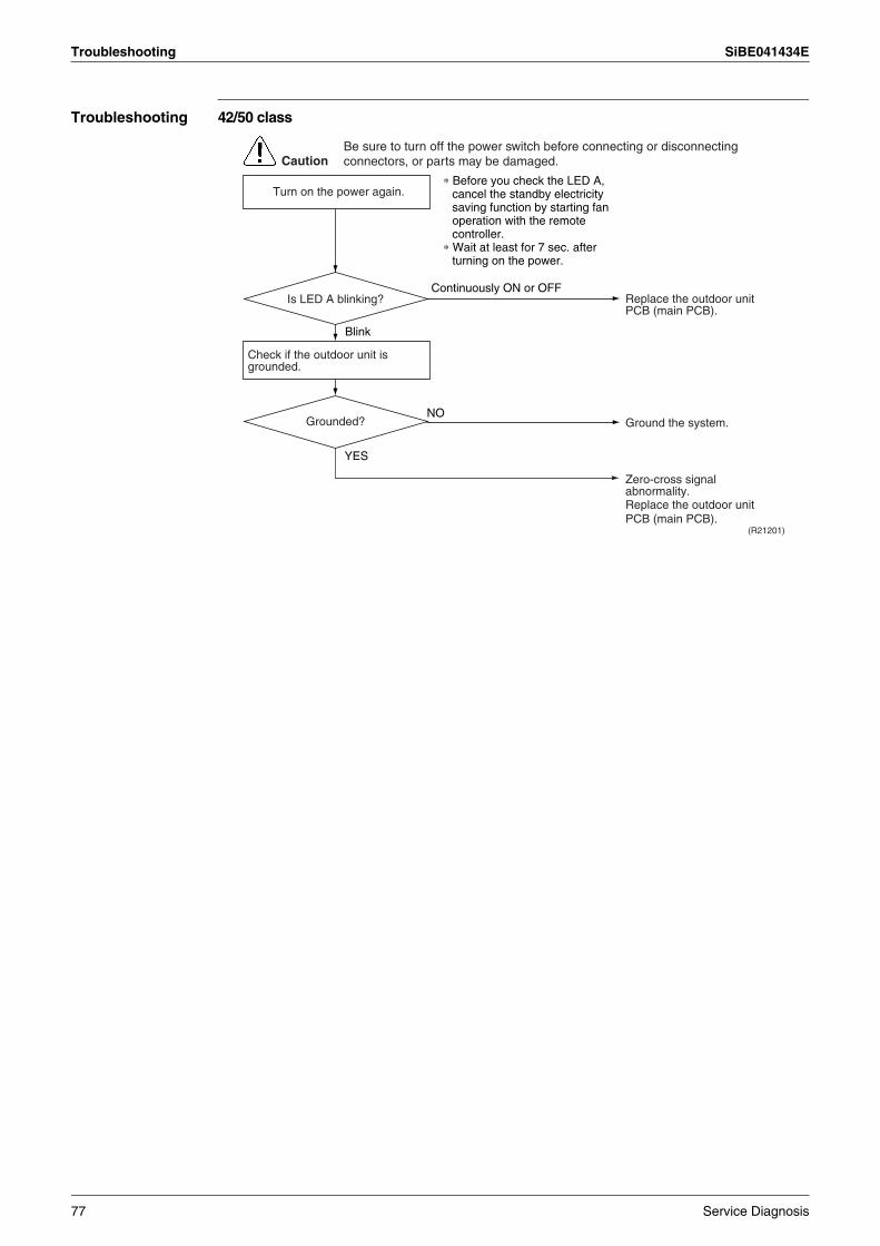
Troubleshooting SiBE041434E
Troubleshooting 42/50 class
CautionBe sure to turn off the power switch before connecting or disconnecting connectors, or parts may be damaged.
Continuously ON or OFF
Blink
YES
(R21201)
NO
Replace the outdoor unit PCB (main PCB).
Ground the system.
Zero-cross signal abnormality.Replace the outdoor unit PCB (main PCB).
Check if the outdoor unit is grounded.
Is LED A blinking?
Grounded?
Turn on the power again.∗ Before you check the LED A,
cancel the standby electricity saving function by starting fan operation with the remote controller.
∗ Wait at least for 7 sec. after turning on the power.
77 Service Diagnosis
SiBE041434E Troubleshooting
4.11 OL Activation (Compressor Overload)
Error Code E5
Method of Error Detection
A compressor overload is detected through compressor OL.
Error Decision Conditions
If the error repeats, the system is shut down.Reset condition: Continuous run for about 60 minutes without any other error
Supposed Causes
Disconnection of discharge pipe thermistorDefective discharge pipe thermistorDisconnection of connector S40Disconnection of 2 terminals of OL (Q1L)Defective OL (Q1L)Broken OL harnessDefective electronic expansion valve or coilDefective four way valve or coilDefective outdoor unit PCBRefrigerant shortageWater mixed in refrigerantDefective stop valve
Service Diagnosis 78
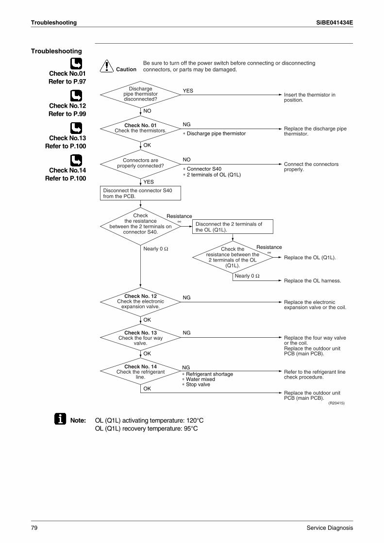
Troubleshooting SiBE041434E
Troubleshooting
Check No.01Refer to P.97
Check No.12Refer to P.99
Check No.13Refer to P.100
Check No.14Refer to P.100
Note: OL (Q1L) activating temperature: 120°COL (Q1L) recovery temperature: 95°C
(R20415)
Caution
YES
NG
∗ Discharge pipe thermistor
NO
OK
OK
NG
NG
OK
YES
NO
NG
OK
∗ Refrigerant shortage∗ Water mixed∗ Stop valve
Disconnect the connector S40 from the PCB.
Disconnect the 2 terminals of the OL (Q1L).
Resistance ∞
Resistance ∞
Nearly 0 Ω
Nearly 0 Ω
∗ Connector S40∗ 2 terminals of OL (Q1L)
Insert the thermistor in position.
Replace the discharge pipe thermistor.
Replace the electronic expansion valve or the coil.
Refer to the refrigerant line check procedure.
Replace the outdoor unit PCB (main PCB).
Replace the four way valve or the coil.Replace the outdoor unit PCB (main PCB).
Discharge pipe thermistor disconnected?
Check No. 01Check the thermistors.
Check No. 13Check the four way
valve.
Check No. 14Check the refrigerant
line.
Check No. 12Check the electronic
expansion valve.
Replace the OL (Q1L).
Replace the OL harness.
Connect the connectors properly.
Connectors are properly connected?
Check the resistance
between the 2 terminals on connector S40.
Check the resistance between the 2 terminals of the OL
(Q1L).
Be sure to turn off the power switch before connecting or disconnecting connectors, or parts may be damaged.
79 Service Diagnosis
SiBE041434E Troubleshooting
4.12 Compressor Lock
Error Code E6
Method of Error Detection
A compressor lock is detected by checking the compressor running condition through the position detection circuit.
Error Decision Conditions
Operation stops due to overcurrent.If the error repeats, the system is shut down.Reset condition: Continuous run for about 11 minutes without any other error
Supposed Causes
Compressor lockedCompressor harness disconnected
Troubleshooting
Check No.12Refer to P.99
Check No.15Refer to P.101
Turn off the power. Disconnect the harnesses U, V, and W.
(R21163)
Caution
NO
YES
YES
NO
NO
YES
Check No.15Check with the inverter analyzer.
Turn off the power and reconnect the harnesses. Turn on the power again and restart the system.
(Precaution before turning on the power again)Make sure the power has been off for at least 30 seconds.
Correct the power supply or replace the outdoor unit PCB (main PCB).
∗ Inverter analyzer: RSUK0917C
Replace the compressor.
Replace the compressor.
Check the electronic expansion valve coil.Replace it as required.Go to Check No. 12.
Any LED off?
Emergency stop without compressor
running?
System shut down after errors repeated
several times?
Be sure to turn off the power switch before connecting or disconnecting connectors, or parts may be damaged.
Service Diagnosis 80
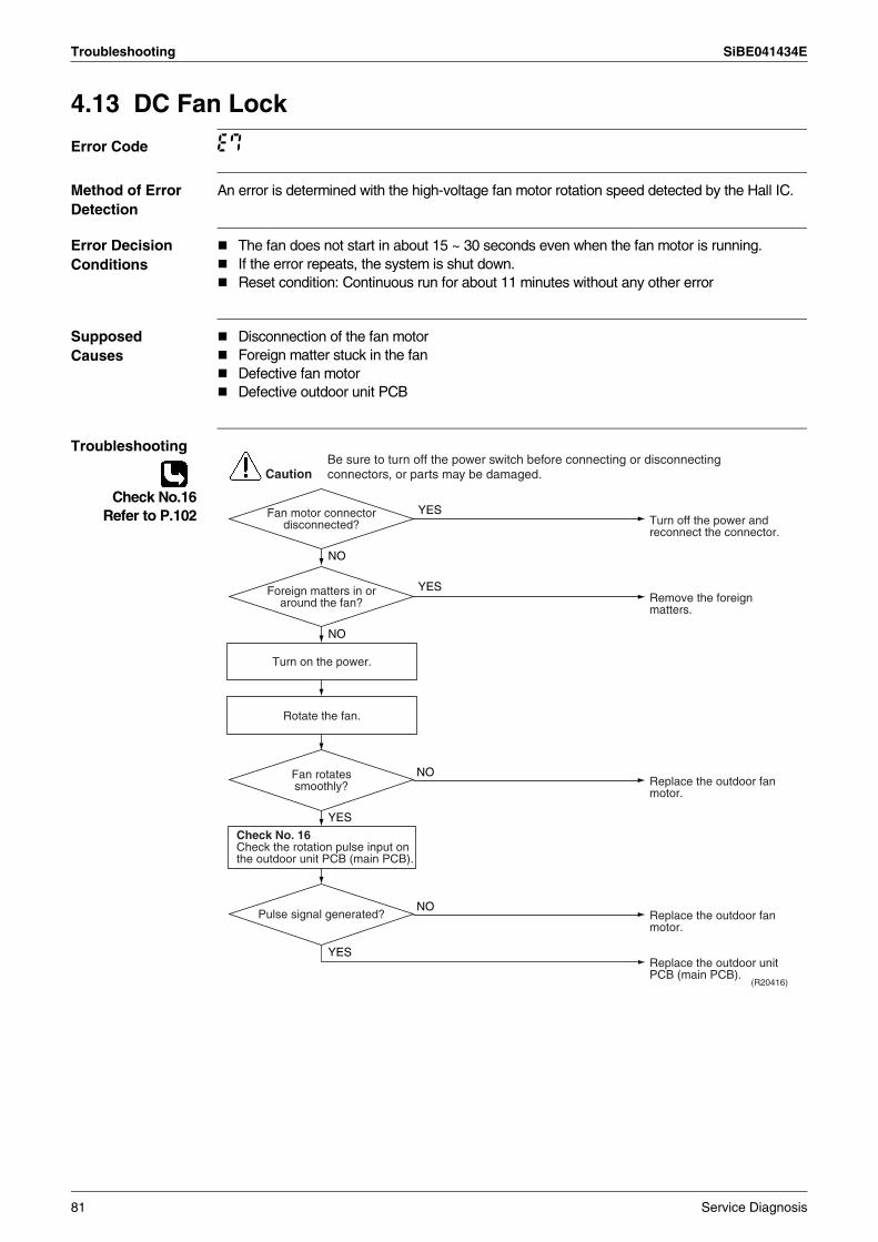
Troubleshooting SiBE041434E
4.13 DC Fan Lock
Error Code E7
Method of Error Detection
An error is determined with the high-voltage fan motor rotation speed detected by the Hall IC.
Error Decision Conditions
The fan does not start in about 15 ~ 30 seconds even when the fan motor is running.If the error repeats, the system is shut down.Reset condition: Continuous run for about 11 minutes without any other error
Supposed Causes
Disconnection of the fan motorForeign matter stuck in the fanDefective fan motorDefective outdoor unit PCB
Troubleshooting
Check No.16Refer to P.102
(R20416)
Caution
YES
YES
NO
YES
NO
NO
YES
NO
Turn on the power.
Rotate the fan.
Check No. 16Check the rotation pulse input on the outdoor unit PCB (main PCB).
Turn off the power and reconnect the connector.
Remove the foreign matters.
Replace the outdoor fan motor.
Replace the outdoor unit PCB (main PCB).
Fan motor connector disconnected?
Foreign matters in or around the fan?
Replace the outdoor fan motor.
Fan rotates smoothly?
Pulse signal generated?
Be sure to turn off the power switch before connecting or disconnecting connectors, or parts may be damaged.
81 Service Diagnosis
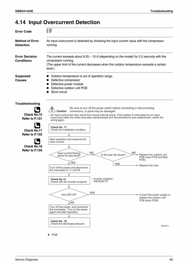
SiBE041434E Troubleshooting
4.14 Input Overcurrent Detection
Error Code E8
Method of Error Detection
An input overcurrent is detected by checking the input current value with the compressor running.
Error Decision Conditions
The current exceeds about 9.25 ~ 10 A (depending on the model) for 2.5 seconds with the compressor running.(The upper limit of the current decreases when the outdoor temperature exceeds a certain level.)
Supposed Causes
Outdoor temperature is out of operation range.Defective compressorDefective power moduleDefective outdoor unit PCBShort circuit
Troubleshooting
Check No.15Refer to P.101
Check No.17Refer to P.103
Check No.18Refer to P.104
CautionBe sure to turn off the power switch before connecting or disconnecting connectors, or parts may be damaged.
∗ An input overcurrent may result from wrong internal wiring. If the system is interrupted by an input overcurrent after the wires have been disconnected and reconnected for part replacement, check the wiring again.
(R20437)
NO NO
YES YES
YES
NO
Start operation and measure the input current.
Check No. 18Check the discharge pressure.
Check No. 17Check the installation condition.
Check No.15Check with the inverter analyzer.
Turn off the power and disconnect the harnesses U, V, and W.
Turn off the power, and reconnect the harnesses. Turn on the power again and start operation.
Replace the outdoor unit PCB (main PCB and filter PCB).
Replace the fuse.
Correct the power supply or replace the outdoor unit PCB (main PCB).
Any LED off?
Input current flowing above its stop level?
∗ Inverter analyzer: RSUK0917C
Is the fuse ( ) blown?
FU3
Service Diagnosis 82
Troubleshooting SiBE041434E
4.15 Four Way Valve Abnormality
Error Code EA
Method of Error Detection
The room temperature thermistor and the indoor heat exchanger thermistor are checked if they function within their normal ranges in each operation mode.
Error Decision Conditions
A following condition continues over 10 minutes after operating for 5 minutes.
< Cooling / Dry >A – B < –5°C
< Heating >B – A < –5°C
A: Room thermistor temperatureB: Indoor heat exchanger temperature
If the error repeats, the system is shut down.Reset condition: Continuous run for about 60 minutes without any other error
Supposed Causes
Disconnection of four way valve coilDefective four way valve, coil, or harnessDefective outdoor unit PCBDefective thermistorRefrigerant shortageWater mixed in refrigerantDefective stop valve
83 Service Diagnosis
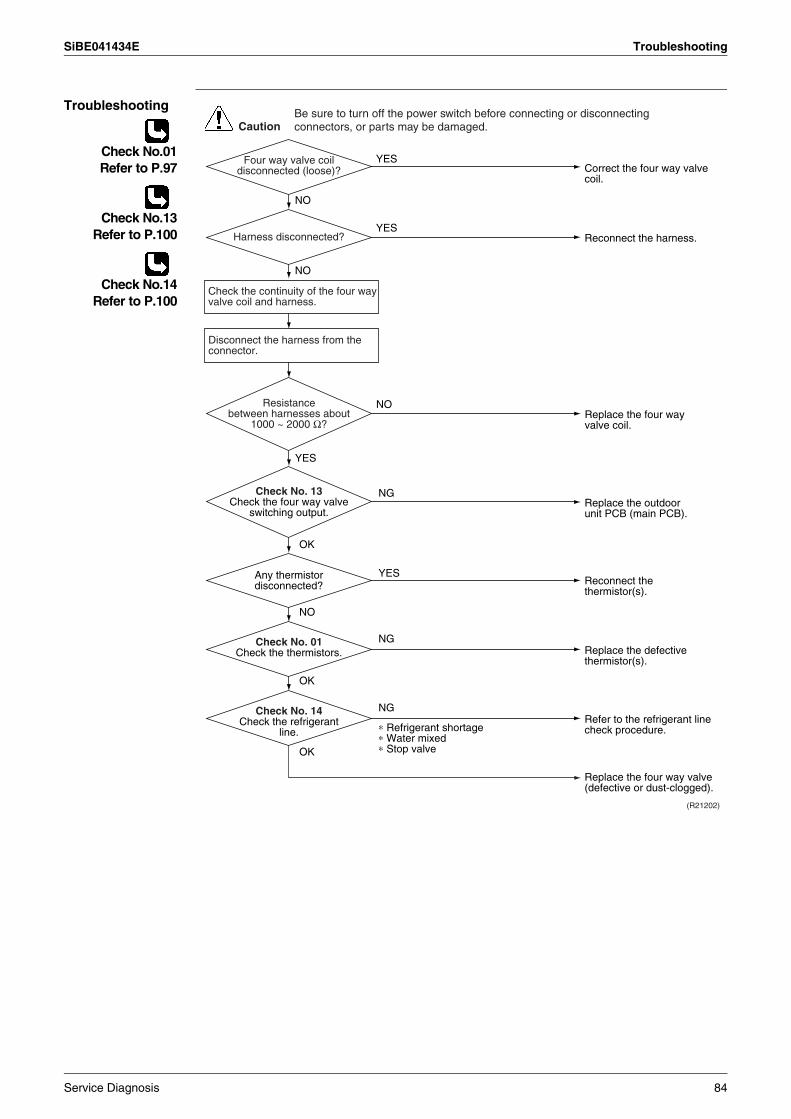
SiBE041434E Troubleshooting
Troubleshooting
Check No.01Refer to P.97
Check No.13Refer to P.100
Check No.14Refer to P.100
NG
OK
NO
OK
NG
OK
YES
NG
Correct the four way valve coil.
Reconnect the harness.
YES
YES
YES
NO
NO
Replace the outdoor unit PCB (main PCB).
Replace the defective thermistor(s).
Refer to the refrigerant line check procedure.
Replace the four way valve (defective or dust-clogged).
Reconnect the thermistor(s).
CautionBe sure to turn off the power switch before connecting or disconnecting connectors, or parts may be damaged.
(R21202)
∗ Refrigerant shortage∗ Water mixed∗ Stop valve
Four way valve coil disconnected (loose)?
Harness disconnected?
Any thermistor disconnected?
Check No. 01Check the thermistors.
Check No. 14Check the refrigerant
line.
Check No. 13Check the four way valve
switching output.
Check the continuity of the four way valve coil and harness.
Replace the four way valve coil.
NOResistance between harnesses about
1000 ~ 2000 Ω?
Disconnect the harness from the connector.
Service Diagnosis 84
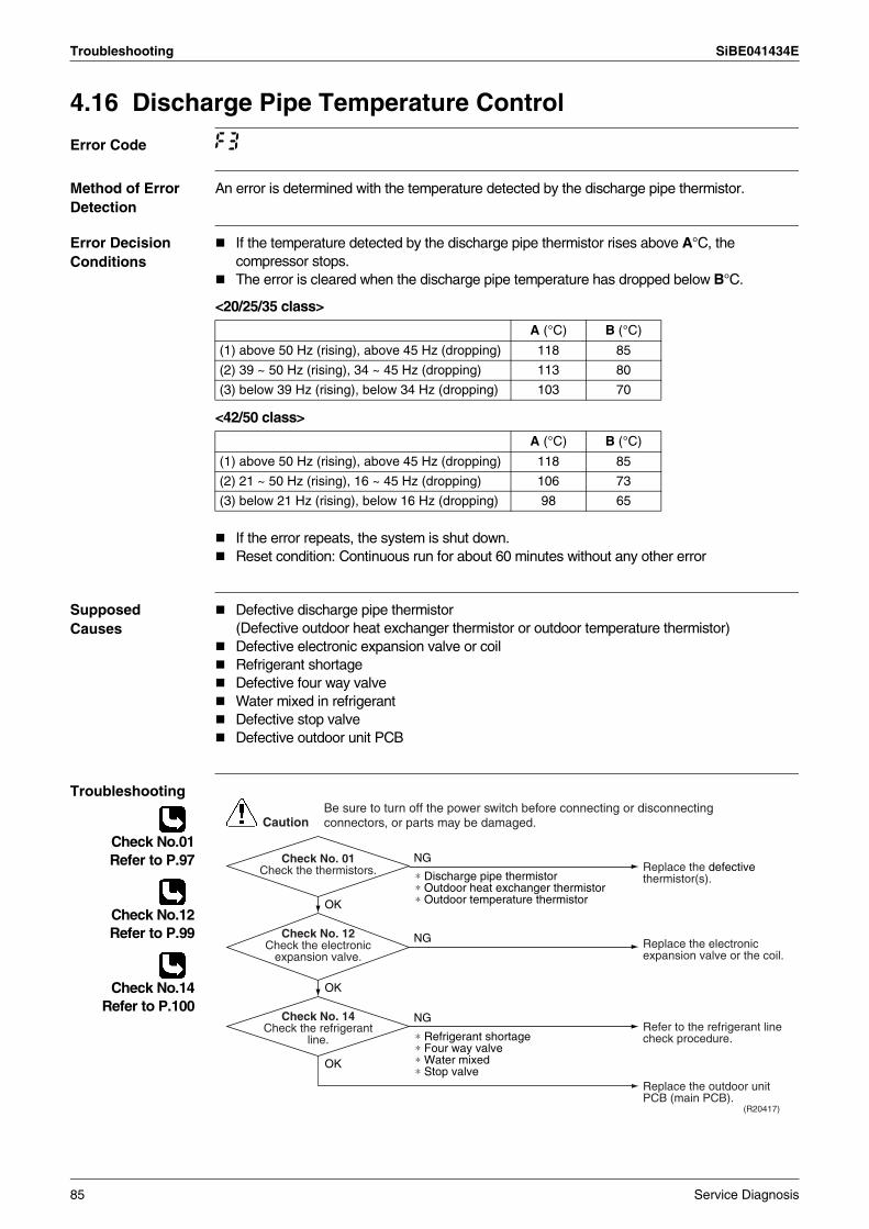
Troubleshooting SiBE041434E
4.16 Discharge Pipe Temperature Control
Error Code F3
Method of Error Detection
An error is determined with the temperature detected by the discharge pipe thermistor.
Error Decision Conditions
If the temperature detected by the discharge pipe thermistor rises above A°C, the compressor stops. The error is cleared when the discharge pipe temperature has dropped below B°C.
<20/25/35 class>
<42/50 class>
If the error repeats, the system is shut down.Reset condition: Continuous run for about 60 minutes without any other error
Supposed Causes
Defective discharge pipe thermistor(Defective outdoor heat exchanger thermistor or outdoor temperature thermistor)Defective electronic expansion valve or coilRefrigerant shortageDefective four way valveWater mixed in refrigerantDefective stop valveDefective outdoor unit PCB
Troubleshooting
Check No.01Refer to P.97
Check No.12Refer to P.99
Check No.14Refer to P.100
A (°C) B (°C)
(1) above 50 Hz (rising), above 45 Hz (dropping) 118 85
(2) 39 ~ 50 Hz (rising), 34 ~ 45 Hz (dropping) 113 80
(3) below 39 Hz (rising), below 34 Hz (dropping) 103 70
A (°C) B (°C)
(1) above 50 Hz (rising), above 45 Hz (dropping) 118 85
(2) 21 ~ 50 Hz (rising), 16 ~ 45 Hz (dropping) 106 73
(3) below 21 Hz (rising), below 16 Hz (dropping) 98 65
(R20417)
Caution
NG
OK
OK
OK
NG
NG
∗ Discharge pipe thermistor∗ Outdoor heat exchanger thermistor∗ Outdoor temperature thermistor
∗ Refrigerant shortage∗ Four way valve∗ Water mixed∗ Stop valve
Check No. 01Check the thermistors.
Check No. 14Check the refrigerant
line.
Check No. 12Check the electronic
expansion valve.
Replace the defective thermistor(s).
Replace the electronic expansion valve or the coil.
Refer to the refrigerant line check procedure.
Replace the outdoor unit PCB (main PCB).
Be sure to turn off the power switch before connecting or disconnecting connectors, or parts may be damaged.
85 Service Diagnosis
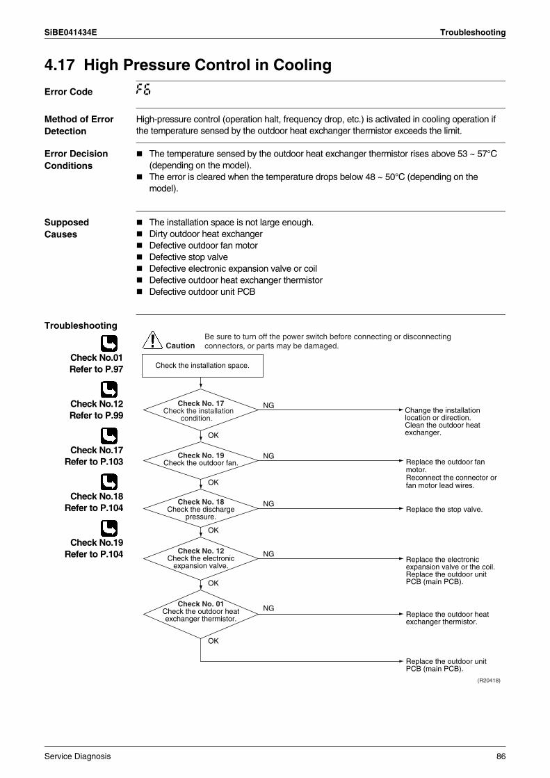
SiBE041434E Troubleshooting
4.17 High Pressure Control in Cooling
Error Code F6
Method of Error Detection
High-pressure control (operation halt, frequency drop, etc.) is activated in cooling operation if the temperature sensed by the outdoor heat exchanger thermistor exceeds the limit.
Error Decision Conditions
The temperature sensed by the outdoor heat exchanger thermistor rises above 53 ~ 57°C (depending on the model).The error is cleared when the temperature drops below 48 ~ 50°C (depending on the model).
Supposed Causes
The installation space is not large enough.Dirty outdoor heat exchangerDefective outdoor fan motorDefective stop valveDefective electronic expansion valve or coilDefective outdoor heat exchanger thermistorDefective outdoor unit PCB
Troubleshooting
Check No.01Refer to P.97
Check No.12Refer to P.99
Check No.17Refer to P.103
Check No.18Refer to P.104
Check No.19Refer to P.104
(R20418)
Caution
Replace the outdoor fan motor.Reconnect the connector or fan motor lead wires.
Replace the stop valve.
Replace the outdoor heat exchanger thermistor.
Replace the outdoor unit PCB (main PCB).
Replace the electronic expansion valve or the coil.Replace the outdoor unit PCB (main PCB).
Change the installation location or direction.Clean the outdoor heat exchanger.
Check the installation space.
NG
OK
OK
NG
NG
OK
OK
OK
NG
NG
Check No. 19Check the outdoor fan.
Check No. 18Check the discharge
pressure.
Check No. 12Check the electronic
expansion valve.
Check No. 01Check the outdoor heat exchanger thermistor.
Check No. 17Check the installation
condition.
Be sure to turn off the power switch before connecting or disconnecting connectors, or parts may be damaged.
Service Diagnosis 86
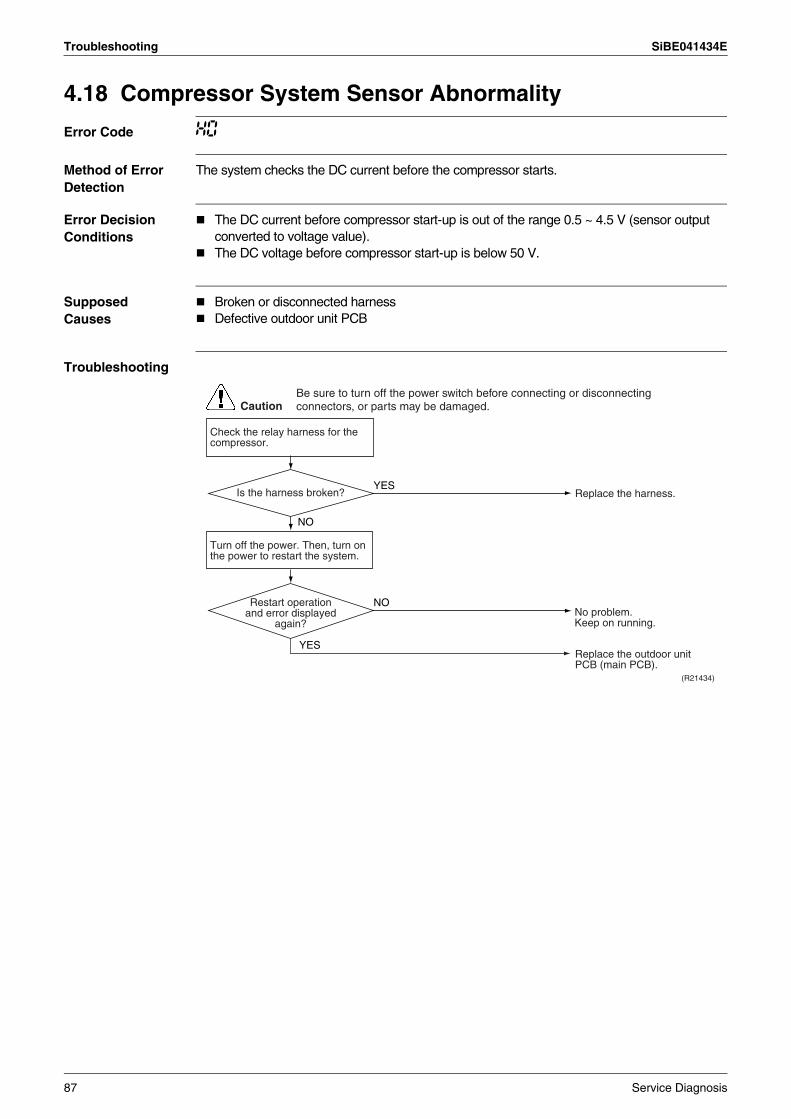
Troubleshooting SiBE041434E
4.18 Compressor System Sensor Abnormality
Error Code H0
Method of Error Detection
The system checks the DC current before the compressor starts.
Error Decision Conditions
The DC current before compressor start-up is out of the range 0.5 ~ 4.5 V (sensor output converted to voltage value).The DC voltage before compressor start-up is below 50 V.
Supposed Causes
Broken or disconnected harness Defective outdoor unit PCB
Troubleshooting
CautionBe sure to turn off the power switch before connecting or disconnecting connectors, or parts may be damaged.
NO
(R21434)
YES
Turn off the power. Then, turn on the power to restart the system.
YES
NO
Replace the harness.
Replace the outdoor unit PCB (main PCB).
Is the harness broken?
Restart operation and error displayed
again?
Check the relay harness for the compressor.
No problem.Keep on running.
87 Service Diagnosis
SiBE041434E Troubleshooting
4.19 Position Sensor Abnormality
Error Code H6
Method of Error Detection
A compressor start-up failure is detected by checking the compressor running condition through the position detection circuit.
Error Decision Conditions
If the error repeats, the system is shut down.Reset condition: Continuous run for about 11 minutes without any other error
Supposed Causes
Disconnection of the compressor relay cableDefective compressorDefective outdoor unit PCBStart-up failure caused by the closed stop valveInput voltage is outside the specified range.
Service Diagnosis 88
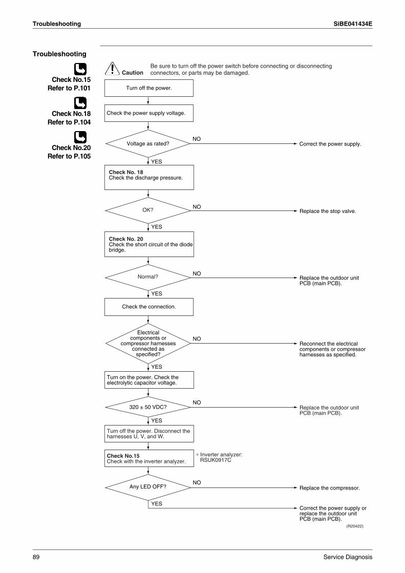
Troubleshooting SiBE041434E
Troubleshooting
Check No.15Refer to P.101
Check No.18Refer to P.104
Check No.20Refer to P.105
CautionBe sure to turn off the power switch before connecting or disconnecting connectors, or parts may be damaged.
NO
YES
Turn off the power.
Check the connection.
Check the power supply voltage.
Correct the power supply.Voltage as rated?
(R20422)
NO
NO
NO
NO
YES
YES
YES
YES
Check No. 20Check the short circuit of the diode bridge.
Check No.15Check with the inverter analyzer.
Turn off the power. Disconnect the harnesses U, V, and W.
Turn on the power. Check the electrolytic capacitor voltage.
Electrical components or
compressor harnesses connected as
specified?
Replace the outdoor unit PCB (main PCB).
Correct the power supply or replace the outdoor unit PCB (main PCB).
Replace the compressor.
Reconnect the electrical components or compressor harnesses as specified.
Replace the outdoor unit PCB (main PCB).
∗ Inverter analyzer: RSUK0917C
Normal?
NO
YES
Check No. 18Check the discharge pressure.
Replace the stop valve.OK?
320 ± 50 VDC?
Any LED OFF?
89 Service Diagnosis
SiBE041434E Troubleshooting
4.20 DC Voltage / Current Sensor Abnormality (20/25/35 Class Only)
Error Code H8
Method of Error Detection
DC voltage or DC current sensor abnormality is identified based on the compressor running frequency and the input current.
Error Decision Conditions
If the error repeats, the system is shut down.Reset condition: Continuous run for about 60 minutes without any other error
Supposed Causes
Defective outdoor unit PCB
Troubleshooting
Replace the outdoor unit PCB (main PCB).
CautionBe sure to turn off the power switch before connecting or disconnecting connectors, or parts may be damaged.
Service Diagnosis 90
Troubleshooting SiBE041434E
4.21 Thermistor or Related Abnormality (Outdoor Unit)
Error Code H9, J3, J6, P4
Method of Error Detection
This fault is identified based on the thermistor input voltage to the microcomputer.A thermistor fault is identified based on the temperature sensed by each thermistor.
Error Decision Conditions
The voltage between the both ends of the thermistor is 4.96 V and more or 0.04 V and less during compressor operation.J3 error is judged if the discharge pipe temperature is lower than the heat exchanger temperature.
Supposed Causes
Disconnection of the connector for the thermistorThermistor corresponding to the error code is defective.Defective heat exchanger thermistor in the case of J3 error (outdoor heat exchanger thermistor in cooling operation, or indoor heat exchanger thermistor in heating operation)Defective outdoor unit PCB
Troubleshooting In case of P4
Replace the outdoor unit PCB (main PCB).
P4 : Radiation fin thermistor
CautionBe sure to turn off the power switch before connecting or disconnecting connectors, or parts may be damaged.
91 Service Diagnosis
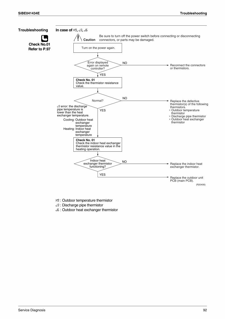
SiBE041434E Troubleshooting
Troubleshooting In case of H9, J3, J6
Check No.01Refer to P.97
H9 : Outdoor temperature thermistorJ3 : Discharge pipe thermistorJ6 : Outdoor heat exchanger thermistor
(R20406)
Caution
NO
YES
YES
NO
NO
YES
Turn on the power again.
Normal?
Reconnect the connectors or thermistors.
J3 error: the discharge pipe temperature is lower than the heat exchanger temperature.
Replace the defective thermistor(s) of the following thermistors.
∗ Outdoor temperature thermistor
∗ Discharge pipe thermistor∗ Outdoor heat exchanger
thermistorCooling: Outdoor heat
exchanger temperature
Heating: Indoor heat exchanger temperature
Replace the indoor heat exchanger thermistor.
Replace the outdoor unit PCB (main PCB).
Error displayed again on remote
controller?
Indoor heat exchanger thermistor
functioning?
Check No. 01Check the thermistor resistance value.
Check No. 01Check the indoor heat exchanger thermistor resistance value in the heating operation.
Be sure to turn off the power switch before connecting or disconnecting connectors, or parts may be damaged.
Service Diagnosis 92
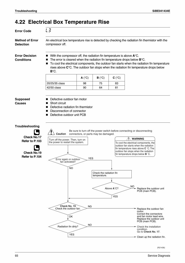
Troubleshooting SiBE041434E
4.22 Electrical Box Temperature Rise
Error Code L3
Method of Error Detection
An electrical box temperature rise is detected by checking the radiation fin thermistor with the compressor off.
Error Decision Conditions
With the compressor off, the radiation fin temperature is above A°C.The error is cleared when the radiation fin temperature drops below B°C.To cool the electrical components, the outdoor fan starts when the radiation fin temperature rises above C°C. The outdoor fan stops when the radiation fin temperature drops below B°C.
Supposed Causes
Defective outdoor fan motorShort circuitDefective radiation fin thermistorDisconnection of connectorDefective outdoor unit PCB
Troubleshooting
Check No.17Refer to P.103
Check No.19Refer to P.104
A (°C) B (°C) C (°C)
20/25/35 class 98 75 83
42/50 class 90 64 81
Caution
WARNING
To cool the electrical components, the outdoor fan starts when the radiation fin temperature rises above C ˚C. The outdoor fan stops when the radiation fin temperature drops below B ˚C.
(R21436)
YES
NO
YES
NG
NO
OK
NO
YES
Turn off the power. Then, turn on the power to restart the system.
Check the radiation fin temperature.
Radiation fin dirty?
Check No. 19Check the outdoor fan.
Error again or outdoor fan activated?
Replace the outdoor unit PCB (main PCB).
Clean up the radiation fin.
Be sure to turn off the power switch before connecting or disconnecting connectors, or parts may be damaged.
Replace the outdoor fan motor.Correct the connectors and fan motor lead wire.Replace the outdoor unit PCB (main PCB).
Above A˚C?
Check the installation condition.Go to Check No. 17.
93 Service Diagnosis
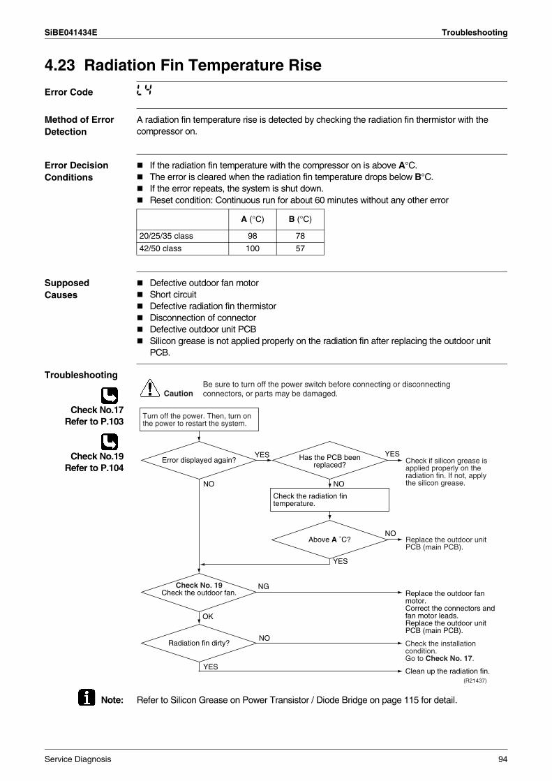
SiBE041434E Troubleshooting
4.23 Radiation Fin Temperature Rise
Error Code L4
Method of Error Detection
A radiation fin temperature rise is detected by checking the radiation fin thermistor with the compressor on.
Error Decision Conditions
If the radiation fin temperature with the compressor on is above A°C.The error is cleared when the radiation fin temperature drops below B°C.If the error repeats, the system is shut down.Reset condition: Continuous run for about 60 minutes without any other error
Supposed Causes
Defective outdoor fan motorShort circuitDefective radiation fin thermistorDisconnection of connectorDefective outdoor unit PCBSilicon grease is not applied properly on the radiation fin after replacing the outdoor unit PCB.
Troubleshooting
Check No.17Refer to P.103
Check No.19Refer to P.104
Note: Refer to Silicon Grease on Power Transistor / Diode Bridge on page 115 for detail.
A (°C) B (°C)
20/25/35 class 98 78
42/50 class 100 57
Caution
Turn off the power. Then, turn on the power to restart the system.
Be sure to turn off the power switch before connecting or disconnecting connectors, or parts may be damaged.
(R21437)
NO
NG
OK
NO
YES
Check the radiation fin temperature.
NO
YESYES
Above A ˚C?
Check No. 19Check the outdoor fan.
Error displayed again? Has the PCB been replaced? Check if silicon grease is
applied properly on the radiation fin. If not, apply the silicon grease.
Replace the outdoor unit PCB (main PCB).
Replace the outdoor fan motor.Correct the connectors and fan motor leads.Replace the outdoor unit PCB (main PCB).
YES
NORadiation fin dirty?
Clean up the radiation fin.
Check the installation condition.Go to Check No. 17.
Service Diagnosis 94
Troubleshooting SiBE041434E
4.24 Output Overcurrent Detection
Error Code L5
Method of Error Detection
An output overcurrent is detected by checking the current that flows in the inverter DC section.
Error Decision Conditions
A position signal error occurs while the compressor is running.A rotation speed error occurs while the compressor is running.An output overcurrent signal is fed from the output overcurrent detection circuit to the microcomputer.If the error repeats, the system is shut down.Reset condition: Continuous run for about 11 minutes without any other error
Supposed Causes
Poor installation conditionClosed stop valveDefective power moduleWrong internal wiringAbnormal power supply voltageDefective outdoor unit PCBDefective compressor
95 Service Diagnosis
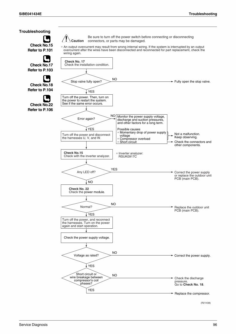
SiBE041434E Troubleshooting
Troubleshooting
Check No.15Refer to P.101
Check No.17Refer to P.103
Check No.18Refer to P.104
Check No.22Refer to P.106
(R21438)
Caution
NO
YES
NO
YES
NO
YES
NO
YES
NO
YES
YES
NO
∗ An output overcurrent may result from wrong internal wiring. If the system is interrupted by an output overcurrent after the wires have been disconnected and reconnected for part replacement, check the wiring again.
Check No. 22
Check No. 17
Check No.15
Turn off the power and disconnect the harnesses U, V, and W.
Turn off the power, and reconnect the harnesses. Turn on the power again and start operation.
Turn off the power. Then, turn on the power to restart the system. See if the same error occurs.
Check the power supply voltage.
Monitor the power supply voltage, discharge and suction pressures, and other factors for a long term.
Possible causes∗ Momentary drop of power supply
voltage∗ Compressor overload∗ Short circuit
Check the installation condition.
Check with the inverter analyzer.
Check the power module.
Not a malfunction.Keep observing.
Check the connectors and other components.
Fully open the stop valve.
Correct the power supply.
Replace the compressor.
Correct the power supply or replace the outdoor unit PCB (main PCB).
Replace the outdoor unit PCB (main PCB).
Error again?
Stop valve fully open?
Voltage as rated?
Any LED off?
Normal?
∗ Inverter analyzer: RSUK0917C
Short circuit or wire breakage between
compressor's coil phases?
Be sure to turn off the power switch before connecting or disconnecting connectors, or parts may be damaged.
Check the discharge pressure.Go to Check No. 18.
Service Diagnosis 96
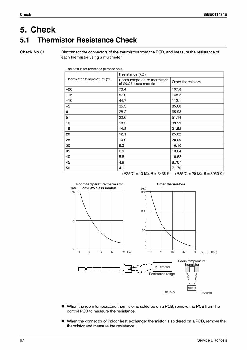
Check SiBE041434E
5. Check5.1 Thermistor Resistance Check
Check No.01 Disconnect the connectors of the thermistors from the PCB, and measure the resistance of each thermistor using a multimeter.
When the room temperature thermistor is soldered on a PCB, remove the PCB from the control PCB to measure the resistance.
When the connector of indoor heat exchanger thermistor is soldered on a PCB, remove the thermistor and measure the resistance.
The data is for reference purpose only.
Thermistor temperature (°C)Resistance (kΩ)
Room temperature thermistor of 20/25 class models Other thermistors
–20 73.4 197.8
–15 57.0 148.2
–10 44.7 112.1
–5 35.3 85.60
0 28.2 65.93
5 22.6 51.14
10 18.3 39.99
15 14.8 31.52
20 12.1 25.02
25 10.0 20.00
30 8.2 16.10
35 6.9 13.04
40 5.8 10.62
45 4.9 8.707
50 4.1 7.176
(R25°C = 10 kΩ, B = 3435 K) (R25°C = 20 kΩ, B = 3950 K)
Room temperature thermistor of 20/25 class models
(˚C)
50
25
0–15 0 15 30 45
(kΩ)
(R11952)
Other thermistors
(˚C)
(kΩ)
–15 0 15 30 45
150
100
50
Multimeter
Resistance range
(R21542)
Multimeter(R20505)
Room temperature thermistor
97 Service Diagnosis
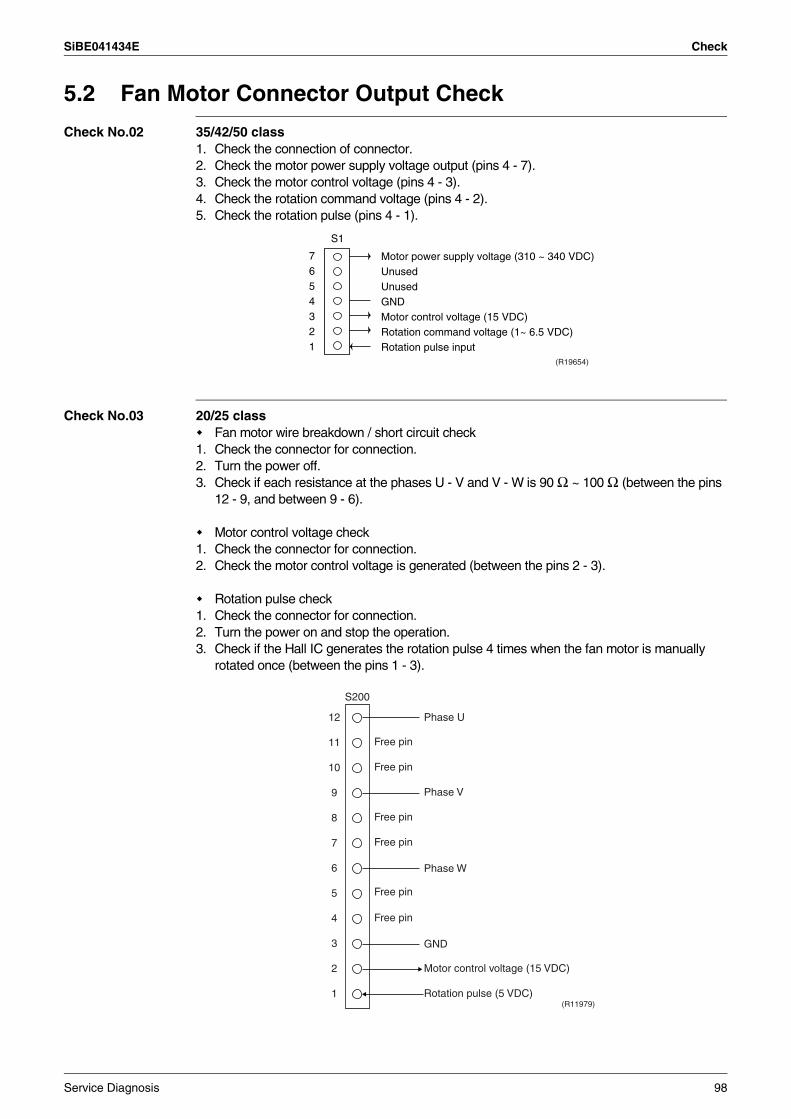
SiBE041434E Check
5.2 Fan Motor Connector Output Check
Check No.02 35/42/50 class1. Check the connection of connector.2. Check the motor power supply voltage output (pins 4 - 7).3. Check the motor control voltage (pins 4 - 3).4. Check the rotation command voltage (pins 4 - 2).5. Check the rotation pulse (pins 4 - 1).
Check No.03 20/25 classFan motor wire breakdown / short circuit check
1. Check the connector for connection.2. Turn the power off. 3. Check if each resistance at the phases U - V and V - W is 90 Ω ~ 100 Ω (between the pins
12 - 9, and between 9 - 6).
Motor control voltage check1. Check the connector for connection.2. Check the motor control voltage is generated (between the pins 2 - 3).
Rotation pulse check1. Check the connector for connection.2. Turn the power on and stop the operation. 3. Check if the Hall IC generates the rotation pulse 4 times when the fan motor is manually
rotated once (between the pins 1 - 3).
7654321
S1
(R19654)
Motor power supply voltage (310 ~ 340 VDC)UnusedUnusedGNDMotor control voltage (15 VDC)Rotation command voltage (1~ 6.5 VDC)Rotation pulse input
(R11979)
12
11
10
9
8
7
6
5
4
3
2
1
Phase U
Free pin
Free pin
Free pin
Free pin
Free pin
Free pin
Phase V
Phase W
GND
Motor control voltage (15 VDC)
Rotation pulse (5 VDC)
S200
Service Diagnosis 98
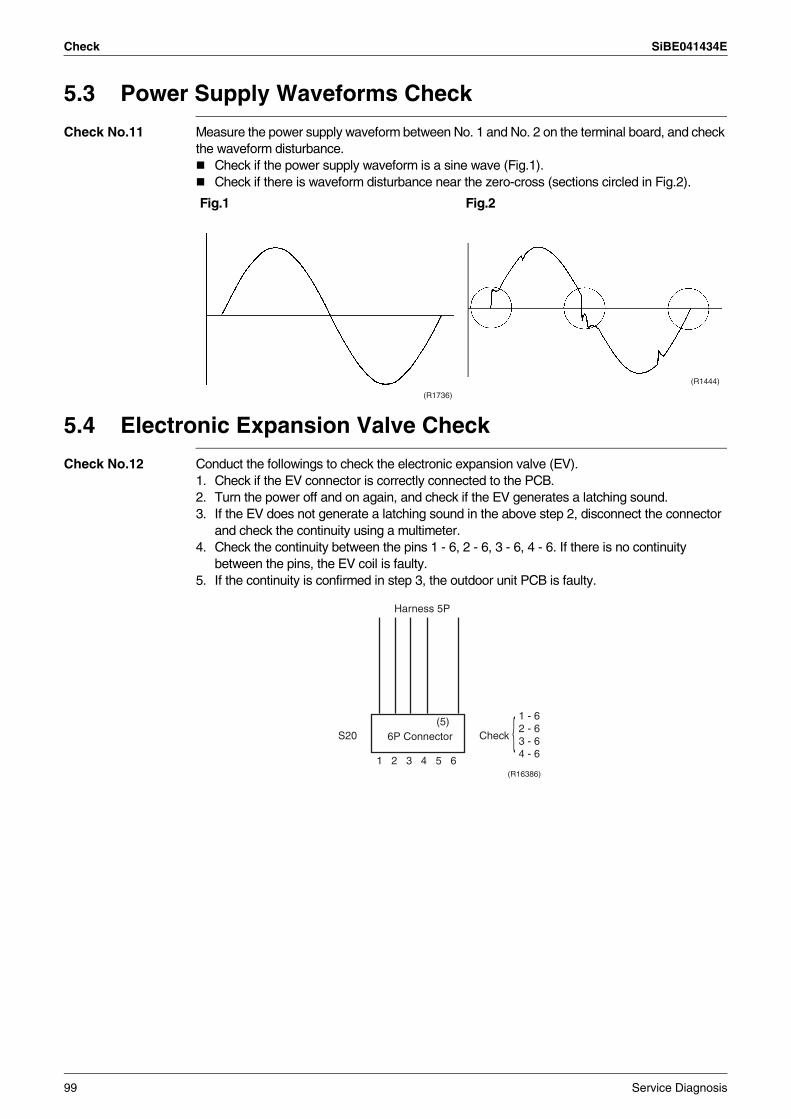
Check SiBE041434E
5.3 Power Supply Waveforms Check
Check No.11 Measure the power supply waveform between No. 1 and No. 2 on the terminal board, and check the waveform disturbance.
Check if the power supply waveform is a sine wave (Fig.1).Check if there is waveform disturbance near the zero-cross (sections circled in Fig.2).
5.4 Electronic Expansion Valve Check
Check No.12 Conduct the followings to check the electronic expansion valve (EV).1. Check if the EV connector is correctly connected to the PCB.2. Turn the power off and on again, and check if the EV generates a latching sound.3. If the EV does not generate a latching sound in the above step 2, disconnect the connector
and check the continuity using a multimeter.4. Check the continuity between the pins 1 - 6, 2 - 6, 3 - 6, 4 - 6. If there is no continuity
between the pins, the EV coil is faulty.5. If the continuity is confirmed in step 3, the outdoor unit PCB is faulty.
Fig.1 Fig.2
(R1736)
(R1444)
Harness 5P
6P Connector(5)
CheckS20
1 - 62 - 63 - 64 - 6
1 2 3 4 5 6(R16386)
99 Service Diagnosis
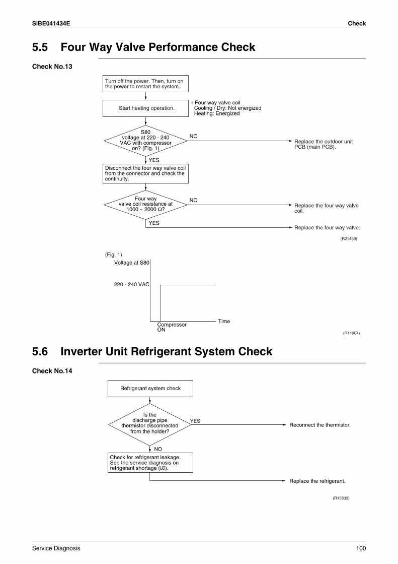
SiBE041434E Check
5.5 Four Way Valve Performance Check
Check No.13
5.6 Inverter Unit Refrigerant System Check
Check No.14
(R21439)
NO
YES
YES
NO
Turn off the power. Then, turn on the power to restart the system.
Disconnect the four way valve coil from the connector and check the continuity.
Start heating operation.∗ Four way valve coil
Cooling / Dry: Not energized Heating: Energized
Replace the outdoor unit PCB (main PCB).
Replace the four way valve coil.
Replace the four way valve.
Four way valve coil resistance at
1000 ~ 2000 Ω?
S80 voltage at 220 - 240
VAC with compressor on? (Fig. 1)
(R11904)
(Fig. 1)
Voltage at S80
220 - 240 VAC
TimeCompressor ON
Refrigerant system check
Check for refrigerant leakage.See the service diagnosis on refrigerant shortage (U0).
(R15833)
YES
NO
Reconnect the thermistor.
Replace the refrigerant.
Is the discharge pipe
thermistor disconnected from the holder?
Service Diagnosis 100
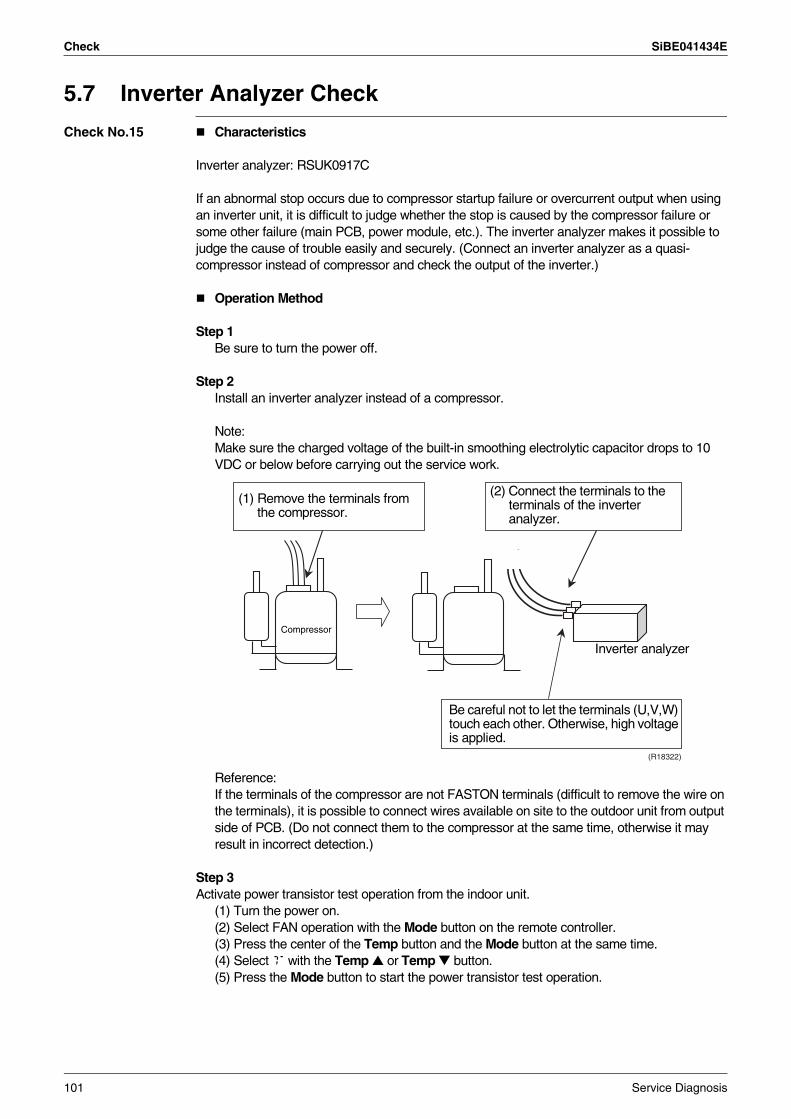
Check SiBE041434E
5.7 Inverter Analyzer Check
Check No.15 Characteristics
Inverter analyzer: RSUK0917C
If an abnormal stop occurs due to compressor startup failure or overcurrent output when using an inverter unit, it is difficult to judge whether the stop is caused by the compressor failure or some other failure (main PCB, power module, etc.). The inverter analyzer makes it possible to judge the cause of trouble easily and securely. (Connect an inverter analyzer as a quasi-compressor instead of compressor and check the output of the inverter.)
Operation Method
Step 1Be sure to turn the power off.
Step 2Install an inverter analyzer instead of a compressor.
Note:Make sure the charged voltage of the built-in smoothing electrolytic capacitor drops to 10 VDC or below before carrying out the service work.
Reference:If the terminals of the compressor are not FASTON terminals (difficult to remove the wire on the terminals), it is possible to connect wires available on site to the outdoor unit from output side of PCB. (Do not connect them to the compressor at the same time, otherwise it may result in incorrect detection.)
Step 3Activate power transistor test operation from the indoor unit.
(1) Turn the power on.(2) Select FAN operation with the Mode button on the remote controller.(3) Press the center of the Temp button and the Mode button at the same time.(4) Select T with the Temp or Temp button.(5) Press the Mode button to start the power transistor test operation.
(R18322)
(1) Remove the terminals from the compressor.
(2) Connect the terminals to the terminals of the inverter analyzer.
Compressor
Inverter analyzer
Be careful not to let the terminals (U,V,W) touch each other. Otherwise, high voltage is applied.
101 Service Diagnosis
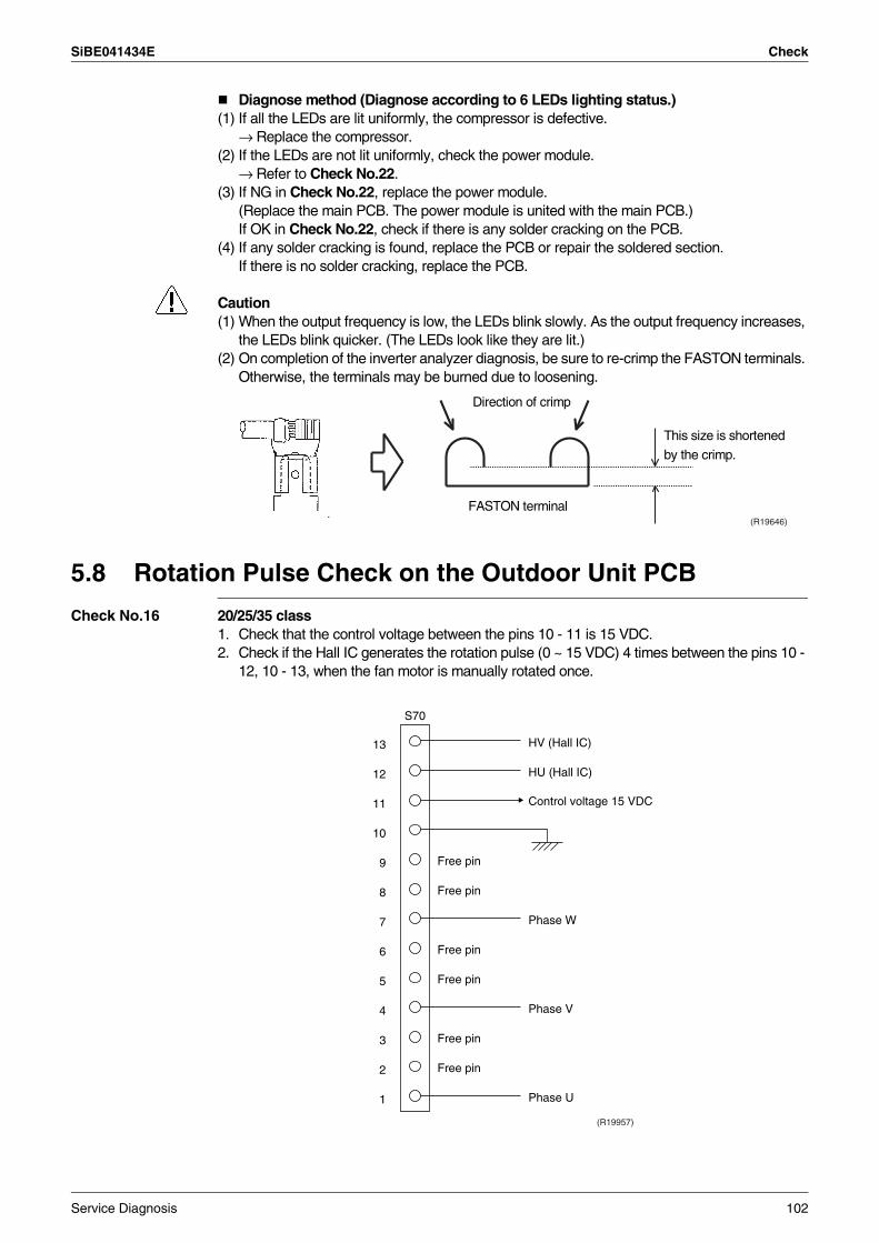
SiBE041434E Check
Diagnose method (Diagnose according to 6 LEDs lighting status.)(1) If all the LEDs are lit uniformly, the compressor is defective.
→ Replace the compressor.(2) If the LEDs are not lit uniformly, check the power module.
→ Refer to Check No.22.(3) If NG in Check No.22, replace the power module.
(Replace the main PCB. The power module is united with the main PCB.)If OK in Check No.22, check if there is any solder cracking on the PCB.
(4) If any solder cracking is found, replace the PCB or repair the soldered section.If there is no solder cracking, replace the PCB.
Caution(1) When the output frequency is low, the LEDs blink slowly. As the output frequency increases,
the LEDs blink quicker. (The LEDs look like they are lit.)(2) On completion of the inverter analyzer diagnosis, be sure to re-crimp the FASTON terminals.
Otherwise, the terminals may be burned due to loosening.
5.8 Rotation Pulse Check on the Outdoor Unit PCB
Check No.16 20/25/35 class1. Check that the control voltage between the pins 10 - 11 is 15 VDC.2. Check if the Hall IC generates the rotation pulse (0 ~ 15 VDC) 4 times between the pins 10 -
12, 10 - 13, when the fan motor is manually rotated once.
(R19646)
Direction of crimp
FASTON terminal
This size is shortened
by the crimp.
13
12
11
10
9
8
7
6
5
4
3
2
1
S70
Phase U
Control voltage 15 VDC
Phase V
Phase W
HU (Hall IC)
HV (Hall IC)
Free pin
Free pin
Free pin
Free pin
Free pin
Free pin
(R19957)
Service Diagnosis 102
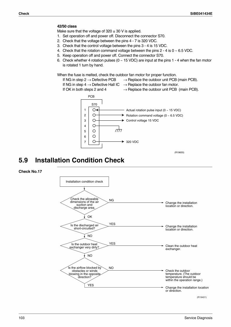
Check SiBE041434E
42/50 classMake sure that the voltage of 320 ± 30 V is applied.1. Set operation off and power off. Disconnect the connector S70.2. Check that the voltage between the pins 4 - 7 is 320 VDC.3. Check that the control voltage between the pins 3 - 4 is 15 VDC.4. Check that the rotation command voltage between the pins 2 - 4 is 0 ~ 6.5 VDC.5. Keep operation off and power off. Connect the connector S70.6. Check whether 4 rotation pulses (0 ~ 15 VDC) are input at the pins 1 - 4 when the fan motor
is rotated 1 turn by hand.
When the fuse is melted, check the outdoor fan motor for proper function.If NG in step 2 → Defective PCB → Replace the outdoor unit PCB (main PCB).If NG in step 4 → Defective Hall IC → Replace the outdoor fan motor.If OK in both steps 2 and 4 → Replace the outdoor unit PCB (main PCB).
5.9 Installation Condition Check
Check No.17
1
2
3
4
5
6
7 320 VDC
(R19655)
S70
PCB
Actual rotation pulse input (0 ~ 15 VDC)
Rotation command voltage (0 ~ 6.5 VDC)
Control voltage 15 VDC
Installation condition check
OK
Check the allowable dimensions of the air
suction and discharge area.
Is the airflow blocked by obstacles or winds
blowing in the opposite direction?
(R19401)
NG
YES
YES
NO
Is the discharged air short-circuited?
NO
NO
YES
Is the outdoor heat exchanger very dirty?
Change the installation location or direction.
Change the installation location or direction.
Clean the outdoor heat exchanger.
Check the outdoor temperature. (The outdoor temperature should be within the operation range.)
Change the installation location or direction.
103 Service Diagnosis
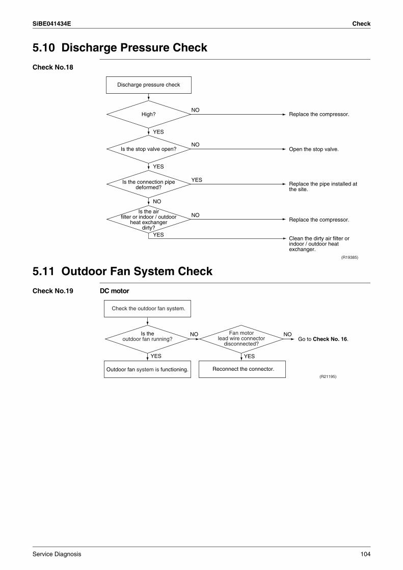
SiBE041434E Check
5.10 Discharge Pressure Check
Check No.18
5.11 Outdoor Fan System Check
Check No.19 DC motor
(R19385)
YES
YES
YES
NO
NO
NO
NO
YES
Is the air filter or indoor / outdoor
heat exchanger dirty?
Is the connection pipe deformed?
Is the stop valve open?
High? Replace the compressor.
Open the stop valve.
Replace the pipe installed at the site.
Clean the dirty air filter or indoor / outdoor heat exchanger.
Replace the compressor.
Discharge pressure check
(R21195)
YES
NONO
YES
Outdoor fan system is functioning.
Check the outdoor fan system.
Reconnect the connector.
Is theoutdoor fan running?
Fan motor lead wire connector
disconnected?Go to Check No. 16.
Service Diagnosis 104
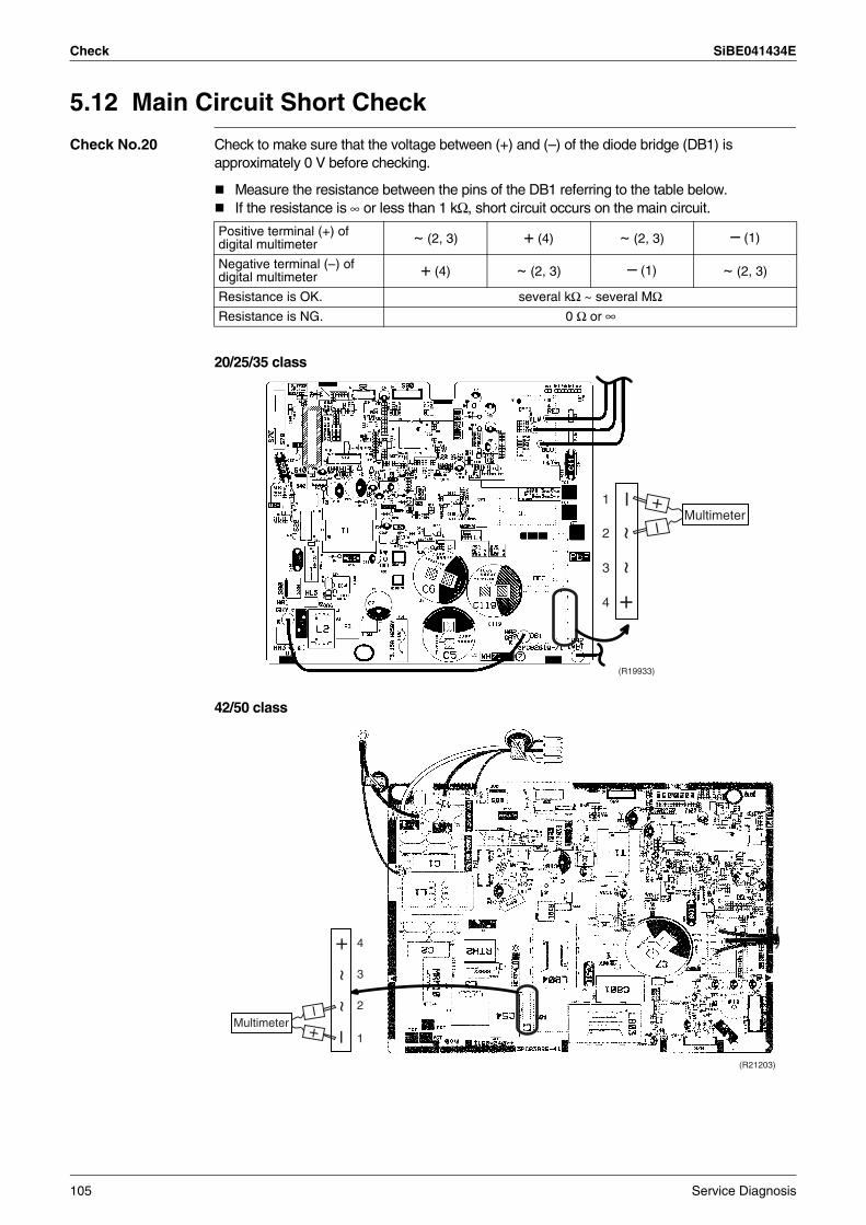
Check SiBE041434E
5.12 Main Circuit Short Check
Check No.20 Check to make sure that the voltage between (+) and (–) of the diode bridge (DB1) is approximately 0 V before checking.
Measure the resistance between the pins of the DB1 referring to the table below.If the resistance is ∞ or less than 1 kΩ, short circuit occurs on the main circuit.
20/25/35 class
42/50 class
Positive terminal (+) of digital multimeter ~ (2, 3) + (4) ~ (2, 3) – (1)
Negative terminal (–) of digital multimeter + (4) ~ (2, 3) – (1) ~ (2, 3)
Resistance is OK. several kΩ ~ several MΩResistance is NG. 0 Ω or ∞
(R19933)
1
2
3
4
Multimeter
–~
~+
–+
(R21203)
1
2
3
4
Multimeter
–~
~+
–+
105 Service Diagnosis
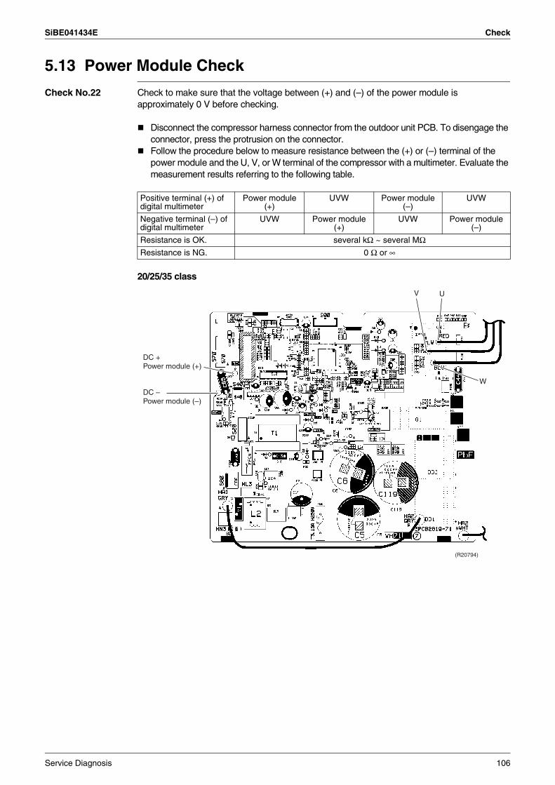
SiBE041434E Check
5.13 Power Module Check
Check No.22 Check to make sure that the voltage between (+) and (–) of the power module is approximately 0 V before checking.
Disconnect the compressor harness connector from the outdoor unit PCB. To disengage the connector, press the protrusion on the connector.Follow the procedure below to measure resistance between the (+) or (–) terminal of the power module and the U, V, or W terminal of the compressor with a multimeter. Evaluate the measurement results referring to the following table.
20/25/35 class
Positive terminal (+) of digital multimeter
Power module (+)
UVW Power module (–)
UVW
Negative terminal (–) of digital multimeter
UVW Power module (+)
UVW Power module (–)
Resistance is OK. several kΩ ~ several MΩResistance is NG. 0 Ω or ∞
(R20794)
V U
W
DC + Power module (+)
DC – Power module (–)
Service Diagnosis 106
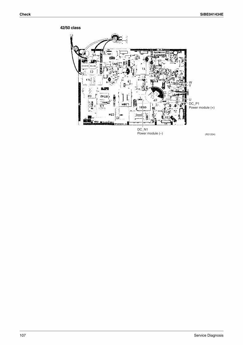
Check SiBE041434E
42/50 class
(R21204)
WV
UDC_P1Power module (+)
DC_N1Power module (–)
107 Service Diagnosis
SiBE041434E
Trial Operation and Field Settings 108
Part 7Trial Operation and
Field Settings
1. Pump Down Operation........................................................................1092. Forced Cooling Operation ...................................................................1103. Trial Operation ....................................................................................1114. Field Settings ......................................................................................112
4.1 When 2 Units are installed in 1 Room ..................................................1124.2 Model Type Setting ..............................................................................1124.3 Facility Setting (cooling at low outdoor temperature) ...........................1134.4 Jumper Settings ...................................................................................114
5. Silicon Grease on Power Transistor / Diode Bridge............................115
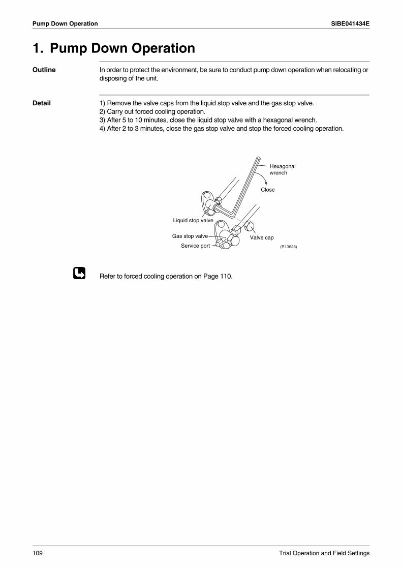
Pump Down Operation SiBE041434E
1. Pump Down OperationOutline In order to protect the environment, be sure to conduct pump down operation when relocating or
disposing of the unit.
Detail 1) Remove the valve caps from the liquid stop valve and the gas stop valve.2) Carry out forced cooling operation.3) After 5 to 10 minutes, close the liquid stop valve with a hexagonal wrench.4) After 2 to 3 minutes, close the gas stop valve and stop the forced cooling operation.
Refer to forced cooling operation on Page 110.
Gas stop valve Valve cap
Close
Liquid stop valve
Service port (R13628)
Hexagonal wrench
109 Trial Operation and Field Settings
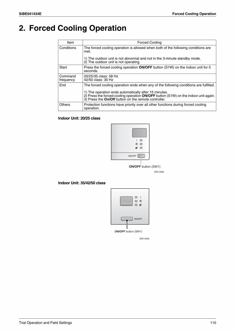
SiBE041434E Forced Cooling Operation
2. Forced Cooling Operation
Indoor Unit: 20/25 class
Indoor Unit: 35/42/50 class
Item Forced Cooling
Conditions The forced cooling operation is allowed when both of the following conditions are met.
1) The outdoor unit is not abnormal and not in the 3-minute standby mode. 2) The outdoor unit is not operating.
Start Press the forced cooling operation ON/OFF button (S1W) on the indoor unit for 5 seconds.
Command frequency
20/25/35 class: 58 Hz42/50 class: 30 Hz
End The forced cooling operation ends when any of the following conditions are fulfilled.
1) The operation ends automatically after 15 minutes.2) Press the forced cooling operation ON/OFF button (S1W) on the indoor unit again.3) Press the On/Off button on the remote controller.
Others Protection functions have priority over all other functions during forced cooling operation.
ON/OFF button (SW1)
(R21339)
ON/OFF button (SW1)
(R21340)
Trial Operation and Field Settings 110
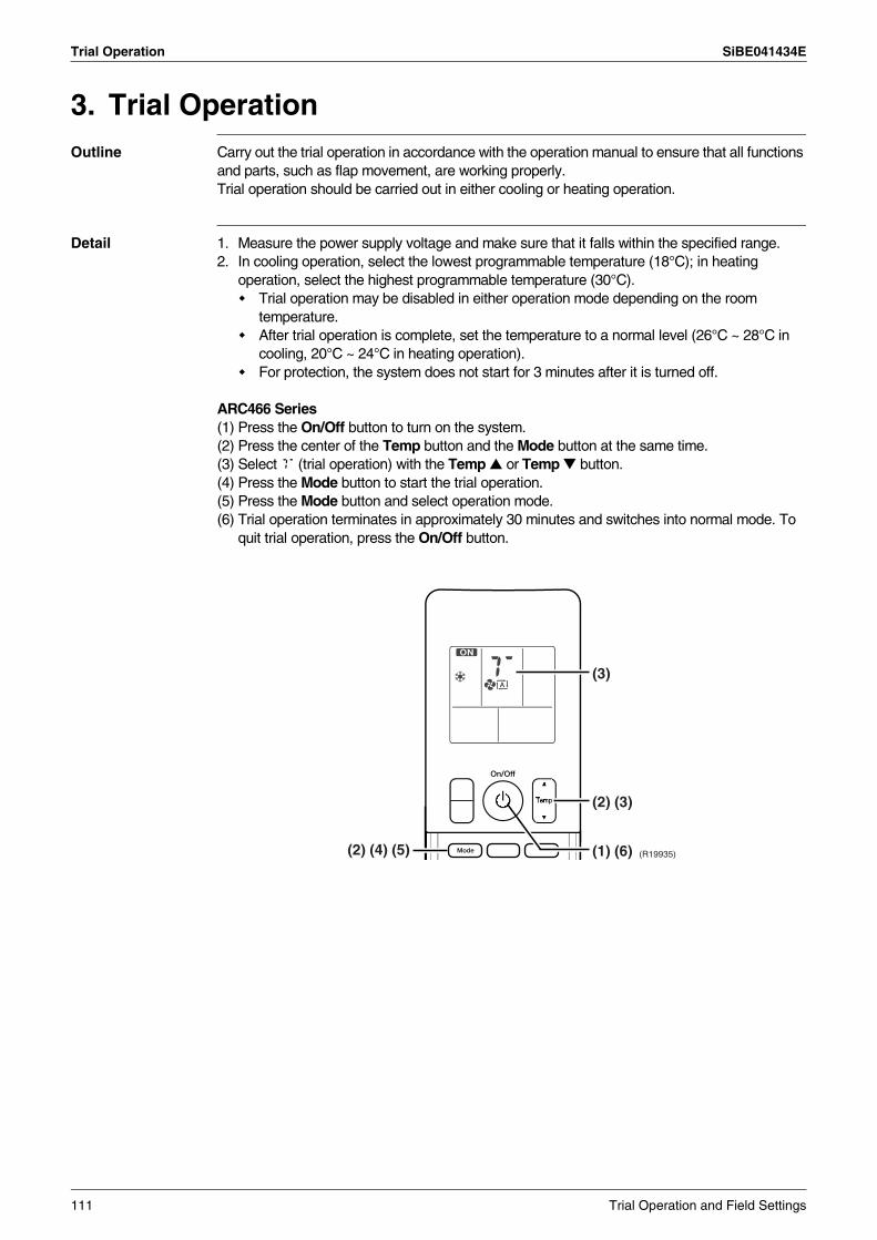
Trial Operation SiBE041434E
3. Trial OperationOutline Carry out the trial operation in accordance with the operation manual to ensure that all functions
and parts, such as flap movement, are working properly.Trial operation should be carried out in either cooling or heating operation.
Detail 1. Measure the power supply voltage and make sure that it falls within the specified range.2. In cooling operation, select the lowest programmable temperature (18°C); in heating
operation, select the highest programmable temperature (30°C).Trial operation may be disabled in either operation mode depending on the room temperature.After trial operation is complete, set the temperature to a normal level (26°C ~ 28°C in cooling, 20°C ~ 24°C in heating operation).For protection, the system does not start for 3 minutes after it is turned off.
ARC466 Series(1) Press the On/Off button to turn on the system.(2) Press the center of the Temp button and the Mode button at the same time.(3) Select T (trial operation) with the Temp or Temp button.(4) Press the Mode button to start the trial operation.(5) Press the Mode button and select operation mode.(6) Trial operation terminates in approximately 30 minutes and switches into normal mode. To
quit trial operation, press the On/Off button.
(R19935)(2) (4) (5) (1) (6)
(2) (3)
(3)
111 Trial Operation and Field Settings
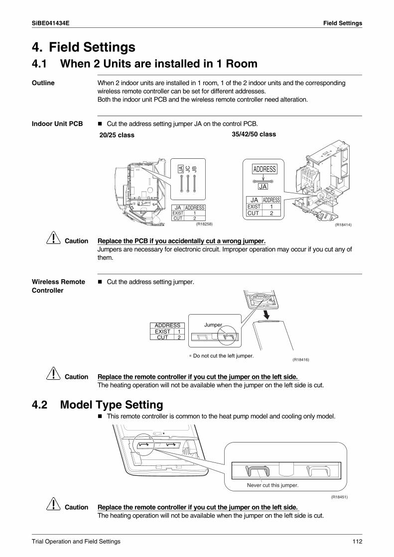
SiBE041434E Field Settings
4. Field Settings4.1 When 2 Units are installed in 1 Room
Outline When 2 indoor units are installed in 1 room, 1 of the 2 indoor units and the corresponding wireless remote controller can be set for different addresses.Both the indoor unit PCB and the wireless remote controller need alteration.
Indoor Unit PCB Cut the address setting jumper JA on the control PCB.
Caution Replace the PCB if you accidentally cut a wrong jumper.Jumpers are necessary for electronic circuit. Improper operation may occur if you cut any of them.
Wireless Remote Controller
Cut the address setting jumper.
Caution Replace the remote controller if you cut the jumper on the left side. The heating operation will not be available when the jumper on the left side is cut.
4.2 Model Type SettingThis remote controller is common to the heat pump model and cooling only model.
Caution Replace the remote controller if you cut the jumper on the left side. The heating operation will not be available when the jumper on the left side is cut.
20/25 class 35/42/50 class
JA JC JB
ADDRESS12
JAEXISTCUT
(R18258)
ADDRESS
JA
ADDRESSJAEXIST 1CUT 2
(R18414)
(R18416)
ADDRESSEXIST 1CUT 2
Jumper
∗ Do not cut the left jumper.
Never cut this jumper.
(R18451)
Trial Operation and Field Settings 112
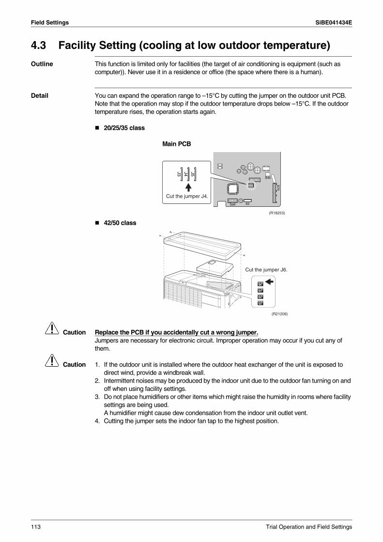
Field Settings SiBE041434E
4.3 Facility Setting (cooling at low outdoor temperature)
Outline This function is limited only for facilities (the target of air conditioning is equipment (such as computer)). Never use it in a residence or office (the space where there is a human).
Detail You can expand the operation range to –15°C by cutting the jumper on the outdoor unit PCB. Note that the operation may stop if the outdoor temperature drops below –15°C. If the outdoor temperature rises, the operation starts again.
20/25/35 class
Main PCB
42/50 class
Caution Replace the PCB if you accidentally cut a wrong jumper.Jumpers are necessary for electronic circuit. Improper operation may occur if you cut any of them.
Caution 1. If the outdoor unit is installed where the outdoor heat exchanger of the unit is exposed to direct wind, provide a windbreak wall.
2. Intermittent noises may be produced by the indoor unit due to the outdoor fan turning on and off when using facility settings.
3. Do not place humidifiers or other items which might raise the humidity in rooms where facility settings are being used.A humidifier might cause dew condensation from the indoor unit outlet vent.
4. Cutting the jumper sets the indoor fan tap to the highest position.
S70
S40
S2S90
J5J4J3
(R18253)
Cut the jumper J4.
Cut the jumper J6.
(R21209)
113 Trial Operation and Field Settings
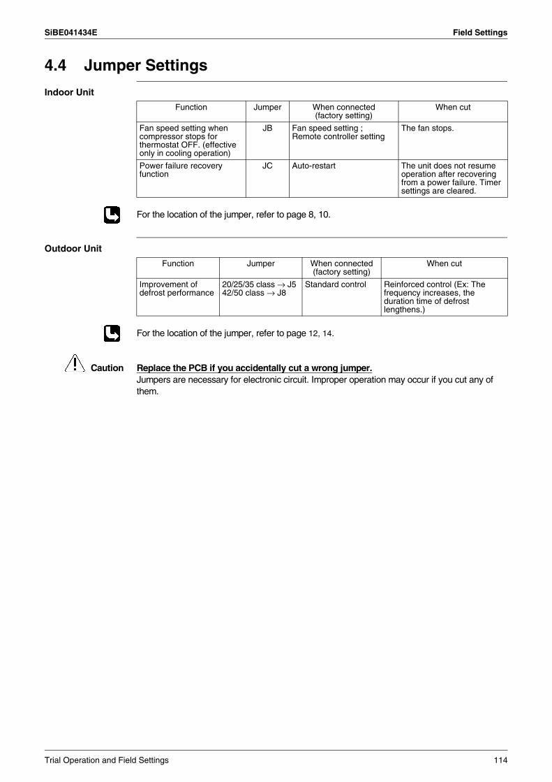
SiBE041434E Field Settings
4.4 Jumper Settings
Indoor Unit
For the location of the jumper, refer to page 8, 10.
Outdoor Unit
For the location of the jumper, refer to page 12, 14.
Caution Replace the PCB if you accidentally cut a wrong jumper.Jumpers are necessary for electronic circuit. Improper operation may occur if you cut any of them.
Function Jumper When connected (factory setting)
When cut
Fan speed setting when compressor stops for thermostat OFF. (effective only in cooling operation)
JB Fan speed setting ;Remote controller setting
The fan stops.
Power failure recovery function
JC Auto-restart The unit does not resume operation after recovering from a power failure. Timer settings are cleared.
Function Jumper When connected (factory setting)
When cut
Improvement of defrost performance
20/25/35 class → J542/50 class → J8
Standard control Reinforced control (Ex: The frequency increases, the duration time of defrost lengthens.)
Trial Operation and Field Settings 114
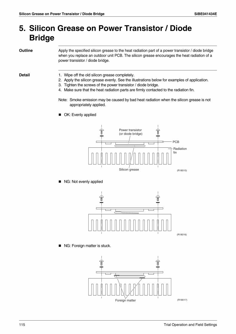
Silicon Grease on Power Transistor / Diode Bridge SiBE041434E
5. Silicon Grease on Power Transistor / Diode Bridge
Outline Apply the specified silicon grease to the heat radiation part of a power transistor / diode bridge when you replace an outdoor unit PCB. The silicon grease encourages the heat radiation of a power transistor / diode bridge.
Detail 1. Wipe off the old silicon grease completely.2. Apply the silicon grease evenly. See the illustrations below for examples of application.3. Tighten the screws of the power transistor / diode bridge.4. Make sure that the heat radiation parts are firmly contacted to the radiation fin.
Note: Smoke emission may be caused by bad heat radiation when the silicon grease is not appropriately applied.
OK: Evenly applied
NG: Not evenly applied
NG: Foreign matter is stuck.
(R18015)
Power transistor (or diode bridge)
Silicon grease
Radiation fin
PCB
(R18016)
Foreign matter (R18017)
115 Trial Operation and Field Settings
SiBE041434E
Appendix 116
Part 8Appendix
1. Piping Diagrams..................................................................................1171.1 Indoor Unit............................................................................................1171.2 Outdoor Unit .........................................................................................119
2. Wiring Diagrams..................................................................................1202.1 Indoor Unit............................................................................................1202.2 Outdoor Unit .........................................................................................121
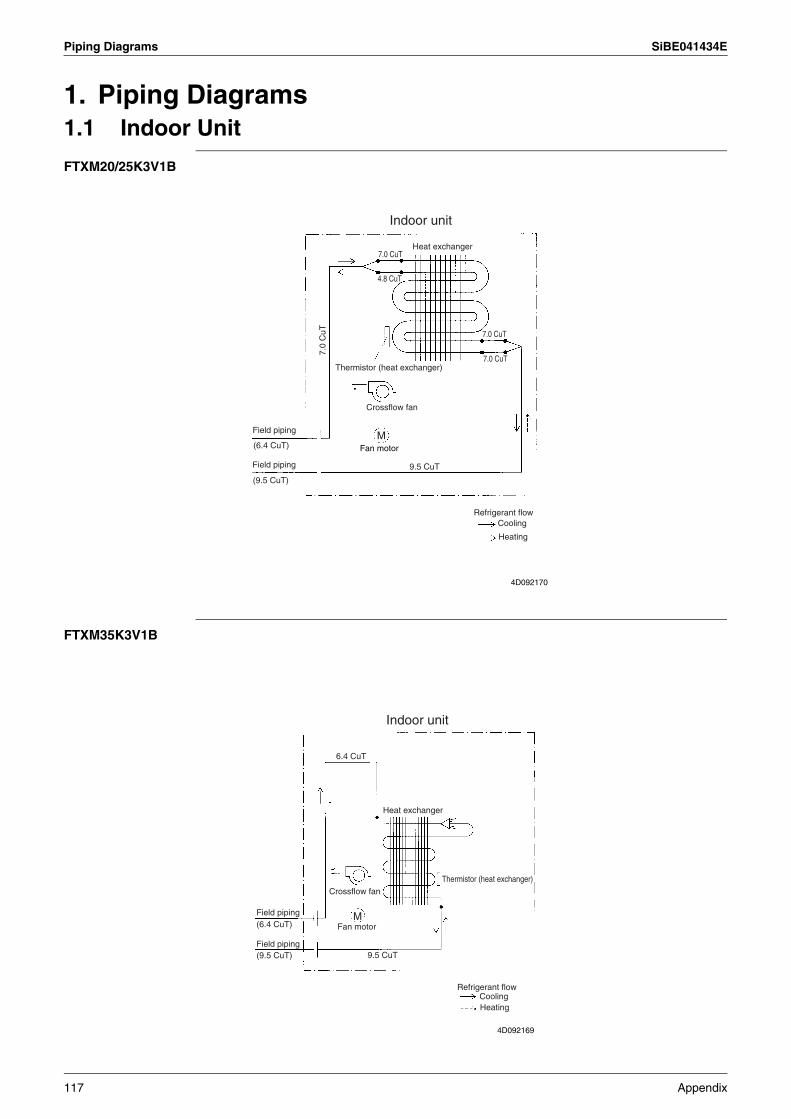
Piping Diagrams SiBE041434E
1. Piping Diagrams1.1 Indoor Unit
FTXM20/25K3V1B
FTXM35K3V1B
4D092170
Field piping
(6.4 CuT)
Field piping
(9.5 CuT)
7.0
CuT
7.0 CuT
4.8 CuT
Indoor unit
Heat exchanger
7.0 CuT
7.0 CuTThermistor (heat exchanger)
Crossflow fan
Fan motorM
9.5 CuT
Refrigerant flowCooling
Heating
Field piping(6.4 CuT)
Field piping(9.5 CuT)
Fan motorM
Crossflow fan
Heat exchanger
6.4 CuT
Thermistor (heat exchanger)
9.5 CuT
Refrigerant flowCoolingHeating
Indoor unit
4D092169
117 Appendix
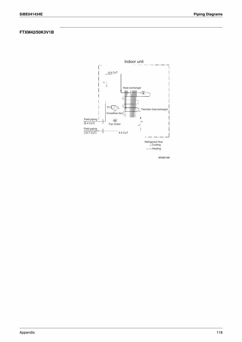
SiBE041434E Piping Diagrams
FTXM42/50K3V1B
Field piping
(6.4 CuT) Fan motor
Crossflow fan
Heat exchanger
Thermistor (heat exchanger)
Refrigerant flowCooling
Heating
Indoor unit
Field piping
(12.7 CuT) 9.5 CuT
6.4 CuT
M
4D092168
Appendix 118
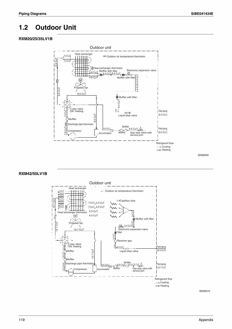
Piping Diagrams SiBE041434E
1.2 Outdoor Unit
RXM20/25/35LV1B
RXM42/50LV1B
9.5
CuT
7.0 CuT
7.0 CuT9.
5 C
uT
9.5 CuT
M
7.9
CuT
Discharge pipe thermistor
7.9
CuT
Compressor
9.5
CuT
9.5 CuT
Accumulator Muffler
Muffler9.5 CuT
(9.5 CuT)
Field piping
(6.4 CuT)
Field piping
Refrigerant flowCoolingHeating
Liquid stop valve6.
4 C
uT
Muffler with filter
φ.4.
0×ID
.2.0
CuT
Muffler with filter
Electronic expansion valve
Heat exchanger
Outdoor unit
Heat exchanger thermistor
4.8 CuT
4.8 CuT Muffler with filter6.4 CuT 6.4 CuT
Outdoor air temperature thermistor
EV
Gas stop valve with service port
3D092005
Propeller fan
4-way valveON: heating
Muffler
12.7
CuT
7.9 CuT
12.7 CuT
M
9.5 C
uT
Discharge pipe thermistor
Compressor
12.7
CuT
9.5 CuT
Accumulator Muffler
Muffler9.5 CuT
(12.7 CuT)Field piping
(6.4 CuT)Field piping
Refrigerant flowCoolingHeating
Liquid stop valve
6.4 C
uT
Electronic expansion valve
Heat exchanger
Outdoor unit
Heat exchanger thermistor4.0 CuT
Muffler with filter
Outdoor air temperature thermistor
EVPropeller fan
4-way valveON: heating
Muffler
7.9 CuT
7.9 CuT7.9 CuT7.9 CuT7.9 CuT7.9 CuT7.9 CuT
12.7
CuT
7.9
CuT
Muffler
7.9 C
uT
9.5 CuT 12.7 CuT
6.4 CuT
Receiver gas
Filter
6.4 CuT 6.4 C
uT6.4
CuT4.0 CuT
4.0 CuT
4.0 CuT7.9 CuT
7.9 CuT
1
2
3
4
1-4Capillary tube
Gas stop valve with service port
3D092010
119 Appendix
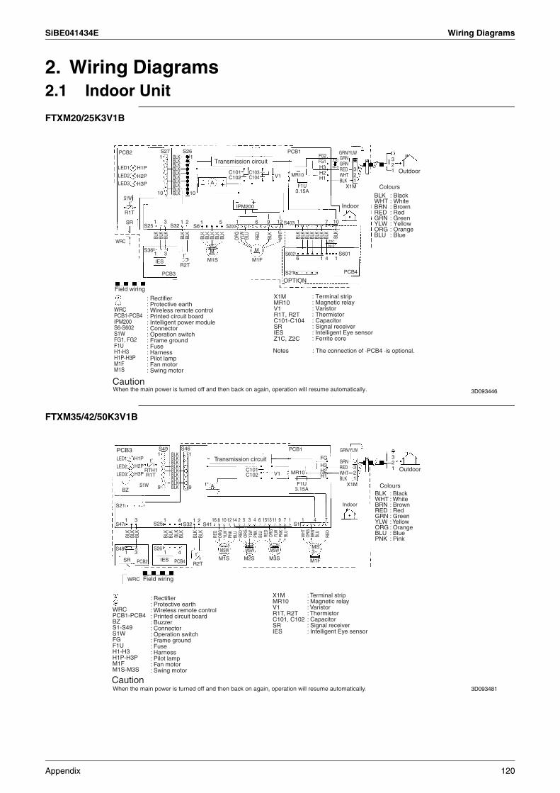
SiBE041434E Wiring Diagrams
2. Wiring Diagrams2.1 Indoor Unit
FTXM20/25K3V1B
FTXM35/42/50K3V1B
BLKPCB2
H1P
S271 1
10 10
S26
H2P
H3P
R1T
SR
S36
S25 S32 S6
IPM200
A
C101 C103C104C102 V1 MR10
F1U3.15A
PCB1
X1M123 1
23
FG2Z1C
N=3
Z2CN=2
FG1H3H2H1
S403
S601S602
S21 PCB4
S200
1 3
1 3 1 12 5 1 1
1 146
7 106
MM
M1S M1F
9 12
IES
PCB3
R2T
WRC
LED1
LED2
LED3
S1Wt˚
t˚
BLKBLKBLKBLK
BLKBLKBLKBLK
BLK
BLK
BLK
BLK
BLK
BLK
BLK
BLK
BLK
BLK
BLK
BLK
BLK
BLK
BLK
BLK
BLK
BLK
BLK
ORG YLW
BLU
RED
BLK
WHT
3D093446
Field wiring
WRCPCB1-PCB4IPM200S6-S602S1WFG1, FG2F1UH1-H3H1P-H3PM1FM1S
: Rectifier: Protective earth: Wireless remote control: Printed circuit board: Intelligent power module: Connector: Operation switch: Frame ground: Fuse: Harness: Pilot lamp: Fan motor: Swing motor
CautionWhen the main power is turned off and then back on again, operation will resume automatically.
X1MMR10V1R1T, R2TC101-C104SRIESZ1C, Z2C
: Terminal strip: Magnetic relay: Varistor: Thermistor: Capacitor: Signal receiver: Intelligent Eye sensor: Ferrite core
Notes : The connection of ·PCB4 ·is optional.
OPTION
Outdoor
ColoursBLKWHTBRNREDGRNYLWORGBLU
: Black: White: Brown: Red: Green: Yellow: Orange: Blue
Indoor
Transmission circuit
GRN/YLWGRNGRNREDWHTBLK
3D093481
BLK
BLK
BLK
BLK
BLK
BLK
BLK
BLK
BLK
Colours
: Rectifier: Protective earth: Wireless remote control: Printed circuit board: Buzzer: Connector: Operation switch: Frame ground: Fuse: Harness: Pilot lamp: Fan motor: Swing motor
WRCPCB1-PCB4BZS1-S49S1WFGF1UH1-H3H1P-H3PM1FM1S-M3S
CautionWhen the main power is turned off and then back on again, operation will resume automatically.
Field wiring
PCB3 S491
9
1
9
LED1
LED2
LED3
H1P
H2PRTH1
BZ
S21
S25 S32 S41S47
S48
1 3 1 4 1 16 10 1214 151311 9 7 1 1 4 7
MS3~MSWMSW
M2S
MSW
M1S M3S M1F
S12 5 3 4 682
1
SR
WRC
IESPCB2 PCB4
3 1S26
4
R1T
S1W
t˚
t˚
R2T
H3P
S46
X1MMR10V1R1T, R2TC101, C102SRIES
: Terminal strip: Magnetic relay: Varistor: Thermistor: Capacitor: Signal receiver: Intelligent Eye sensor
BLKWHTBRNREDGRNYLWORGBLUPNK
: Black: White: Brown: Red: Green: Yellow: Orange: Blue: Pink
Outdoor
Indoor
F1U3.15A
PCB1
MR10
FGH3H2H1
X1M123 1
23
V1C101C102
A
Transmission circuit
RED
ORG
YLW
PNK
BLU
RED
ORG
YLW
PNK
BLU
RED
ORG
YLW
PNK
BLU
WHT
ORG
BRN
BLU
RED
BLKBLKBLKBLKBLKBLKBLKBLKBLK
GRNREDWHTBLK
GRN/YLW
Appendix 120
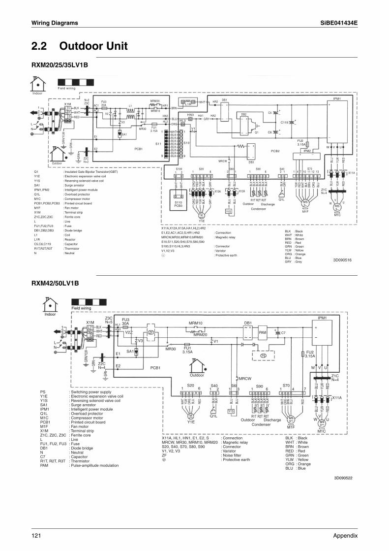
Wiring Diagrams SiBE041434E
2.2 Outdoor Unit
RXM20/25/35LV1B
RXM42/50LV1B
Indoor
Field wiring
123
L
N
X1MLN
123
BLK
WHT
RED
N=2Z3C
AC1
AC2
S
FU320A
V2
L1
V3
MRM20
HR1
MRM10
HN2
HL2
FU13.15A
MR30
SA1
GR
N/Y
LW
GR
N
GR
N
Outdoor
Z2CN=2
E1
E2 PCB1
1
S11
9
BRN
BLU
ORG
WHTBLKBLKBLKBLKBLKBLKBLKBLK
L1R
HN3
HL3
V11
S10
9
WHT
HA1GRY
HA2
HR2 DB1
DB2
Q1
C5
~
~ –
+
~
~ –
+–+
–+
–+
C6
C119
W V UIPM2
FU23.15A
PCB2
–
+
IPM1
~ –
~ +
+ –
BLU
YLW
RE
D
X11A
MRCW DB3
S1001 2 1 6 3 1 1 6 2 1 1 4 7 10 11 12 13
S20 S80 S90 S40 S70
WH
T
WH
T
ORG RE
DYL
WBL
K
GRY
ORG RE
DYL
WBL
K
GRY
BLU
BLU
BLU
BLU
BLK
BLK
BLK
BLK
BLK
BLK
BLK
GRY
YLW
RED
WHT
BLK
BRN
ORG BLU BL
U
YLW
RED
WV
US110PCB3
M
Y1E
Y1S
X13A X12A
R1T R2T R3TOutdoor Discharge
Condenser
Q1LMS3~
M1FM1C
MS3~
Z1CN=4
Q1
Y1E
Y1S
SA1
IPM1,IPM2
Q1L
M1C
PCB1,PCB2,PCB3
M1F
X1M
Z1C,Z2C,Z3C
L
FU1,FU2,FU3
DB1,DB2,DB3
L1
L1R
C5,C6,C119
R1T,R2T,R3T
N
: Insulated Gate Bipolar Transistor(IGBT)
: Electronic expansion valve coil
: Reversing solenoid valve coil
: Surge arrestor
: Intelligent power module
: Overload protector
: Compressor motor
: Printed circuit board
: Fan motor
: Terminal strip
: Ferrite core
: Live
: Fuse
: Diode bridge
: Coil
: Reactor
: Capacitor
: Thermistor
: Neutral
X11A,X12A,X13A,HA1,HL2,HR2
E1,E2,AC1,AC2,S,HR1,HN2
MRCW,MR30,MRM10,MRM20
S10,S11,S20,S40,S70,S80,S90
S100,S110,HL3,HN3
V1,V2,V3
: Connection
: Magnetic relay
: Connector
: Varistor
: Protective earth
BLKWHTBRNREDGRNYLWORGBLUGRY
: Black: White: Brown: Red: Green: Yellow: Orange: Blue: Grey 3D090516
Indoor
Field wiring
~
123
~ ++
+DB1
IPM1
LN
X1MLN
123
Z3CN=5 FU3
30A
FU13.15A FU2
3.15A
Z1CN=4
X11A
BLKWHTRED
GRN/
YLW
GRN
GRN
Z2CN=4
E1
E2
SA1
V2
V3
HN1
HL1
S ZF
PS
PCB1
MR30
MRM10
MRM20
V1
Outdoor
1 6 1 2 1 3S20 S40 S80
6 1 4 7
W V U
WV
U
1S90 S70
MRCW
PAM C7
BLU
YLW
RED
BLU
YLW
RED
M1CM1F
MS 3~
MS 3~
CondenserOutdoor
Q1L
Y1E
MDischarge
R1T R2T R3T
t˚t˚t˚ WHTBL
KBL
KBL
KBL
KBL
KBL
K
BLK
BLK
BLU
BLU
ORG BR
NBL
U
RED
WHT
ORG BL
U
YLW
RED
Y1S
PSY1EY1SSA1IPM1Q1LM1CPCB1M1FX1MZ1C, Z2C, Z3CLFU1, FU2, FU3DB1NC7R1T, R2T, R3TPAM
: Switching power supply: Electronic expansion valve coil: Reversing solenoid valve coil: Surge arrestor: Intelligent power module: Overload protector: Compressor motor: Printed circuit board: Fan motor: Terminal strip: Ferrite core: Live: Fuse: Diode bridge: Neutral: Capacitor: Thermistor: Pulse-amplitude modulation
X11A, HL1, HN1, E1, E2, SMRCW, MR30, MRM10, MRM20S20, S40, S70, S80, S90V1, V2, V3ZF
: Connection: Magnetic relay: Connector: Varistor: Noise filter: Protective earth
BLKWHTBRNREDGRNYLWORGBLU
: Black: White: Brown: Red: Green: Yellow: Orange: Blue
3D090522
121 Appendix
Revision History
Month / Year Version Revised contents
02 / 2015 SiBE041434E First edition
Head Office:Umeda Center Bldg., 2-4-12, Nakazaki-Nishi,Kita-ku, Osaka, 530-8323 Japan
Tokyo Office:JR Shinagawa East Bldg., 2-18-1, Konan,Minato-ku, Tokyo, 108-0075 Japan
http://www.daikin.com/products/ac/
All rights reservedc
Warning Daikin products are manufactured for export to numerous countries throughout the world. Prior to purchase, please confirm with your local authorised importer, distributor and/or retailer whether this product conforms to the applicable standards, and is suitable for use, in the region where the product will be used. This statement does not purport to exclude, restrict or modify the application of any local legislation.
Ask a qualified installer or contractor to install this product. Do not try to install the product yourself. Improper installation can result in water or refrigerant leakage, electrical shock, fire or explosion.
Use only those parts and accessories supplied or specified by Daikin. Ask a qualified installer or contractor to install those parts and accessories. Use of unauthorised parts and accessories or improper installation of parts and accessories can result in water or refrigerant leakage, electrical shock, fire or explosion.
Read the user's manual carefully before using this product. The user's manual provides important safety instructions and warnings. Be sure to follow these instructions and warnings.
If you have any enquiries, please contact your local importer, distributor and/or retailer.
Cautions on product corrosion1. Air conditioners should not be installed in areas where corrosive gases, such as acid gas or alkaline gas, are produced.2. If the outdoor unit is to be installed close to the sea shore, direct exposure to the sea breeze should be avoided. If you need to install
the outdoor unit close to the sea shore, contact your local distributor.
Dealer
Specifications, designs and other content appearing in this brochure are current as of February 2015 but subject to change without notice.SiBE041434E02/2015 AK.B


![PACKAGEHEATPUMPSFEATURING INDUSTRYSTANDARDR-410A REFRIGERANT · []indicatesmetricconversion installationinstructions packageheatpumpsfeaturing industrystandardr-410a refrigerant rqrm15/16seerseries–(2](https://img.pdfslide.net/doc/110x75/5becfdaf09d3f270058ba733/packageheatpumpsfeaturing-industrystandardr-410a-indicatesmetricconversion.jpg)


![PACKAGEHEATPUMPSFEATURING INDUSTRYSTANDARDR-410A … · 2019. 4. 11. · []indicatesmetricconversion installationinstructions packageheatpumpsfeaturing industrystandardr-410a refrigerant](https://img.pdfslide.net/doc/110x75/5ff73f17096e4b21c6037881/packageheatpumpsfeaturing-industrystandardr-410a-2019-4-11-indicatesmetricconversion.jpg)
![PACKAGEHEATPUMPSFEATURING INDUSTRYSTANDARDR-410A … · 2020. 3. 17. · []indicatesmetricconversion installationinstructions packageheatpumpsfeaturing industrystandardr-410a refrigerant](https://img.pdfslide.net/doc/110x75/5ff73ec723717515a65c591b/packageheatpumpsfeaturing-industrystandardr-410a-2020-3-17-indicatesmetricconversion.jpg)
![Freon 410A · 2019. 10. 17. · New tables of the thermodynamic properties of Freon™ 410A refrigerant (ASHRAE designation: R-410A [50/50]), have been developed and are presented](https://img.pdfslide.net/doc/110x75/60b627c139ff3c2213239567/freon-410a-2019-10-17-new-tables-of-the-thermodynamic-properties-of-freona.jpg)