Embed Size (px)
Citation preview
EPSON Stylus PHOTO 875DC
Color ink jet printer
®
SE VICE MANUALSE VICE MANUALSE VICE MANUALSE VICE MANUAL
RRRRSEIJ99015
EPSON Stylus PHOTO 875DC Revision A
2
r transmitted in any form or by any ten permission of SEIKO EPSON
ould any errors be detected, SEIKO
any errors in this manual or the
e trademarks or registered trademarks
Notice:
! All rights reserved. No part of this manual may be reproduced, stored in a retrieval system, omeans, electronic, mechanical, photocopying, recording, or otherwise, without the prior writCORPORATION.
! The contents of this manual are subject to change without notice.
! All effort have been made to ensure the accuracy of the contents of this manual. However, shEPSON would greatly appreciate being informed of them.
! The above not withstanding SEIKO EPSON CORPORATION can assume no responsibility forconsequences thereof.
EPSON is a registered trademark of SEIKO EPSON CORPORATION.
General Notice: Other product names used herein are for identification purpose only and may bof their respective owners. EPSON disclaims any and all rights in those marks.
Copyright © 1999 SEIKO EPSON CORPORATION. Printed in Japan.
EPSON Stylus PHOTO 875DC Revision A
3
Pr age to equipment.
DA y. Great caution should be exercised in
W
Th aintenance procedures.
1. PERFORMING ANY MAINTENANCE
2. ETY MEASURES AS DICTATED FOR
3. NIT TO A POWER SOURCE UNTIL REME CAUTION IN WORKING ON
1. IR TECHNICIAN.2. D ON THE SERIAL NUMBER/RATING
WER SOURCE, DO NOT CONNECT IT
3. SOURCE BEFORE REMOVING OR
4. RGE EQUIPMENT, SUCH AS ANTI-
5. UFACTURE; INTRODUCTION OF T AND VOID ANY APPLICABLE EPSON
PRECAUTIONS
ecautionary notations throughout the text are categorized relative to 1)Personal injury and 2) dam
NGER Signals a precaution which, if ignored, could result in serious or fatal personal injurperforming procedures preceded by DANGER Headings.
ARNING Signals a precaution which, if ignored, could result in damage to equipment.
e precautionary measures itemized below should always be observed when performing repair/m
DANGER
ALWAYS DISCONNECT THE PRODUCT FROM THE POWER SOURCE AND PERIPHERAL DEVICESOR REPAIR PROCEDURES.NOWORK SHOULD BE PERFORMED ON THE UNIT BY PERSONS UNFAMILIAR WITH BASIC SAFALL ELECTRONICS TECHNICIANS IN THEIR LINE OF WORK.WHEN PERFORMING TESTING AS DICTATED WITHIN THIS MANUAL, DO NOT CONNECT THE UINSTRUCTED TO DO SO. WHEN THE POWER SUPPLY CABLE MUST BE CONNECTED, USE EXTPOWER SUPPLY AND OTHER ELECTRONIC COMPONENTS.
WARNING
REPAIRS ON EPSON PRODUCT SHOULD BE PERFORMED ONLY BY AN EPSON CERTIFIED REPAMAKE CERTAIN THAT THE SOURCE VOLTAGES IS THE SAME AS THE RATED VOLTAGE, LISTEPLATE. IF THE EPSON PRODUCT HAS A PRIMARY AC RATING DIFFERENT FROM AVAILABLE POTO THE POWER SOURCE.ALWAYS VERIFY THAT THE EPSON PRODUCT HAS BEEN DISCONNECTED FROM THE POWER REPLACING PRINTED CIRCUIT BOARDS AND/OR INDIVIDUAL CHIPS.IN ORDER TO PROTECT SENSITIVE MICROPROCESSORS AND CIRCUITRY, USE STATIC DISCHASTATIC WRIST STRAPS, WHEN ACCESSING INTERNAL COMPONENTS.REPLACE MALFUNCTIONING COMPONENTS ONLY WITH THOSE COMPONENTS BY THE MANSECOND-SOURCE ICs OR OTHER NONAPPROVED COMPONENTS MAY DAMAGE THE PRODUCWARRANTY.
EPSON Stylus PHOTO 875DC Revision A
4
Th and repair procedures of EPSON Stylus PH pair technicians, and attention should be
oduct.
g the
proved
PREFACE
is manual describes basic functions, theory of electrical and mechanical operations, maintenance OTO 875DC. The instructions and procedures included herein are intended for the experienced re given to the precautions on the preceding page. The chapters are organized as follows:
CHAPTER 1. PRODUCT DESCRIPTIONSProvides a general overview and specifications of the product.
CHAPTER 2. OPERATING PRINCIPLESDescribes the theory of electrical and mechanical operations of the pr
CHAPTER 3. TROUBLESHOOTINGProvides the step-by-step procedures for troubleshooting.
CHAPTER 4. DISASSEMBLY AND ASSEMBLYDescribes the step-by-step procedures for disassembling and assemblinproduct.
CHAPTER 5. ADJUSTMENTSProvides Epson-approved methods for adjustment.
CHAPTER 6. MAINTENANCEProvides preventive maintenance procedures and the lists of Epson-aplubricants and adhesives required for servicing the product.
APPENDIXProvides the following additional information for reference:
• EEPROM Address Map• Connector Pin Assignments• Component Layout• Exploded Diagrams• Electrical Board Circuit Diagrams
EPSON Stylus PHOTO 875DC Revision A
5
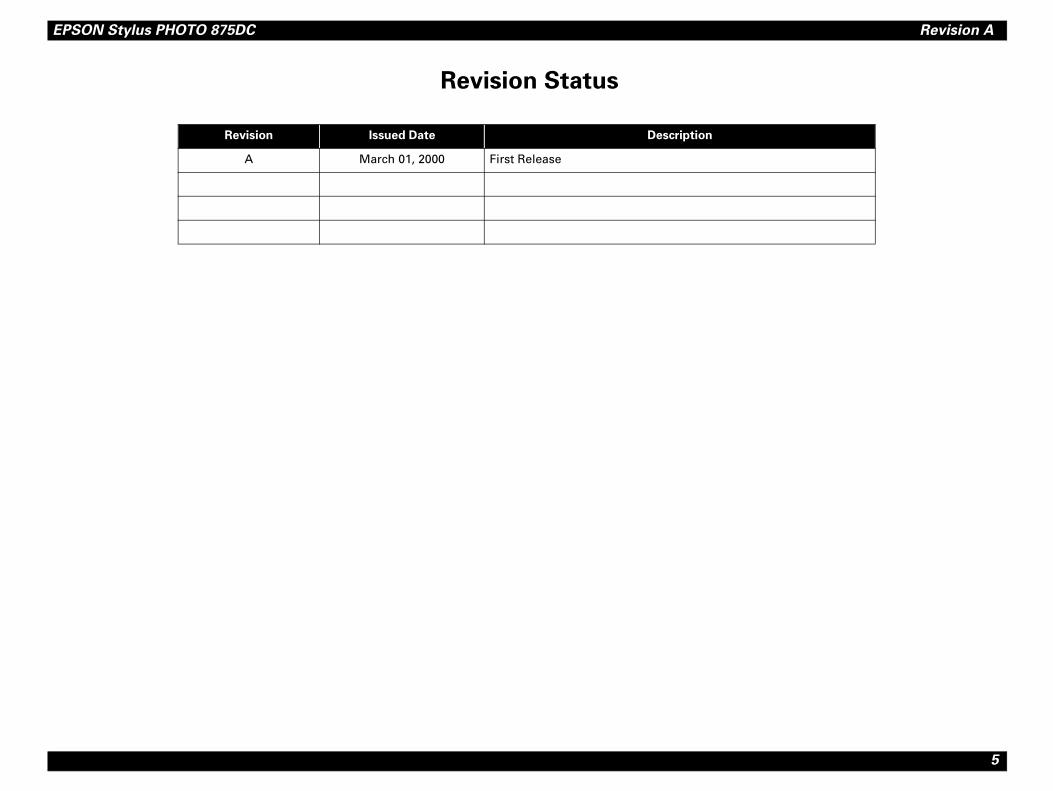
Revision Status
Revision Issued Date Description
A March 01, 2000 First Release
EPSON Stylus PHOTO 875DC Revision A
6
PR
Ov
Ba
Int
Fu
................................................................... 18tem............................................................ 18 manager ................................................. 18
................................................................... 19
................................................................... 21
................................................................... 21.................................................................. 23................................................................... 23................................................................... 23.................................................................. 23................................................................... 24
................................................................... 26
MBLY
................................................................... 28
g the Printer............................................ 28.................................................................. 29
................................................................... 30................................................................. 31
.................................................................. 32
................................................................... 33
................................................................... 34oval........................................................... 36
................................................................... 38
.................................................................. 38
.................................................................. 38
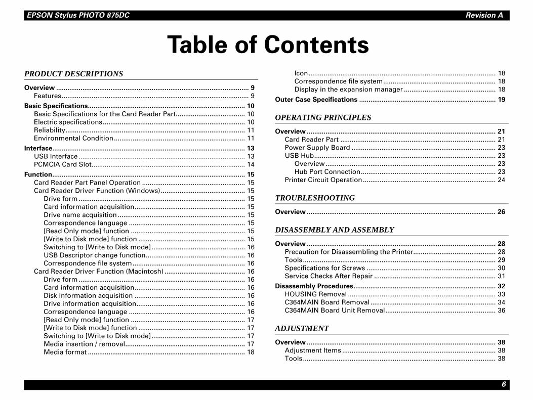
Table of ContentsODUCT DESCRIPTIONS
erview ....................................................................................................... 9
Features.................................................................................................... 9
sic Specifications.................................................................................... 10
Basic Specifications for the Card Reader Part..................................... 10Electric specifications............................................................................ 10Reliability................................................................................................ 11Environmental Condition...................................................................... 11
erface....................................................................................................... 13
USB Interface ......................................................................................... 13PCMCIA Card Slot.................................................................................. 14
nction....................................................................................................... 15
Card Reader Part Panel Operation ....................................................... 15Card Reader Driver Function (Windows)............................................. 15
Drive form ......................................................................................... 15Card information acquisition........................................................... 15Drive name acquisition .................................................................... 15Correspondence language .............................................................. 15[Read Only mode] function ............................................................. 15[Write to Disk mode] function ......................................................... 15Switching to [Write to Disk mode].................................................. 16USB Descriptor change function..................................................... 16Correspondence file system............................................................ 16
Card Reader Driver Function (Macintosh) ........................................... 16Drive form ......................................................................................... 16Card information acquisition........................................................... 16Disk information acquisition ........................................................... 16Drive information acquisition.......................................................... 16Correspondence language .............................................................. 16[Read Only mode] function ............................................................. 17[Write to Disk mode] function ......................................................... 17Switching to [Write to Disk mode].................................................. 17Media insertion / removal................................................................ 17Media format .................................................................................... 18
Icon.................................Correspondence file sysDisplay in the expansion
Outer Case Specifications ......
OPERATING PRINCIPLES
Overview ..................................
Card Reader Part ................Power Supply Board ...........USB Hub..............................
Overview........................Hub Port Connection......
Printer Circuit Operation....
TROUBLESHOOTING
Overview ..................................
DISASSEMBLY AND ASSE
Overview ..................................
Precaution for DisassemblinTools.....................................Specifications for Screws ..Service Checks After Repair
Disassembly Procedures..........
HOUSING Removal ............C364MAIN Board RemovalC364MAIN Board Unit Rem
ADJUSTMENT
Overview ..................................
Adjustment Items ................Tools.....................................
EPSON Stylus PHOTO 875DC Revision A
7
Ad
M
Ov
AP
Co
Cir
Ex
Ele
justment ................................................................................................. 39
Adjustment Using the Adjustment Program....................................... 39About the Adjustment Program...................................................... 39How to Install the Program.............................................................. 39Starting the Service Program.......................................................... 40
USB ID Input .......................................................................................... 41Memory Card Drive Firmware Uploading ........................................... 43
Copying the firmware to the PCMCIA Card ................................... 43Uploading the Memory Card Driver Firmware .............................. 43Checking for the Memory Card Drive Firmware Version.............. 44
AINTENANCE
erview ..................................................................................................... 46
PENDIX
nnector Summary .................................................................................. 48
cuit Board Component Layout ............................................................. 51
ploded Diagrams .................................................................................... 55
ctrical Circuit Board Diagrams ............................................................. 61

C H A P T E R
1PRO CT DESCRIPTIONS
DU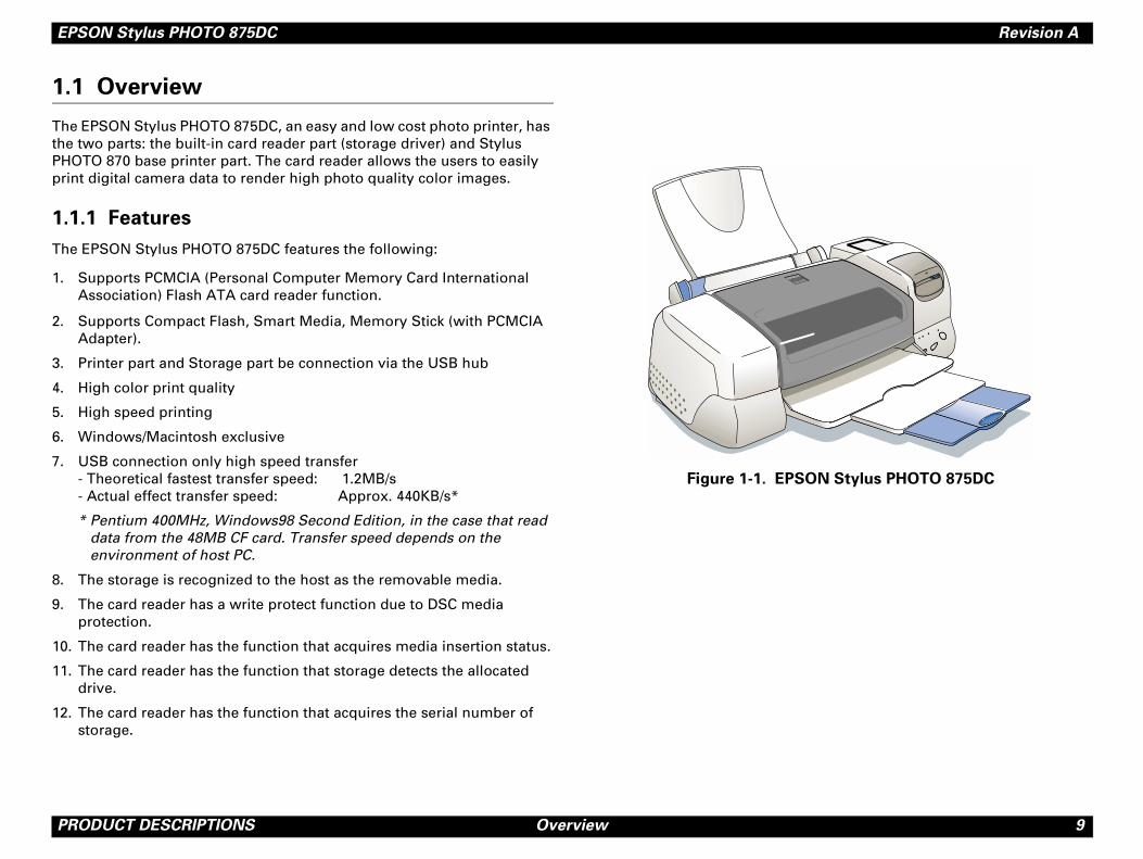
EPSON Stylus PHOTO 875DC Revision A
P 9
1.
ThthePHpri
1.
Th
1.
2.
3.
4.
5.
6.
7.
8.
9.
10
11
12
SON Stylus PHOTO 875DC
RODUCT DESCRIPTIONS Overview
1 Overview
e EPSON Stylus PHOTO 875DC, an easy and low cost photo printer, has two parts: the built-in card reader part (storage driver) and Stylus OTO 870 base printer part. The card reader allows the users to easily nt digital camera data to render high photo quality color images.
1.1 Features
e EPSON Stylus PHOTO 875DC features the following:
Supports PCMCIA (Personal Computer Memory Card International Association) Flash ATA card reader function.
Supports Compact Flash, Smart Media, Memory Stick (with PCMCIA Adapter).
Printer part and Storage part be connection via the USB hub
High color print quality
High speed printing
Windows/Macintosh exclusive
USB connection only high speed transfer- Theoretical fastest transfer speed: 1.2MB/s- Actual effect transfer speed: Approx. 440KB/s*
* Pentium 400MHz, Windows98 Second Edition, in the case that read data from the 48MB CF card. Transfer speed depends on the environment of host PC.
The storage is recognized to the host as the removable media.
The card reader has a write protect function due to DSC media protection.
. The card reader has the function that acquires media insertion status.
. The card reader has the function that storage detects the allocated drive.
. The card reader has the function that acquires the serial number of storage.
Figure 1-1. EP
EPSON Stylus PHOTO 875DC Revision A
P 10
1.
ThpaPH
1.
EN
ThSto
"
"
fication Revision 1.0
BI Transport Specification v1.0 RC5
rd for Information Systems - Reduced Block D
ations
C 100 - 120V
C 99 - 132V
0 - 60Hz
9.5 - 60.5Hz
.4 A
pprox. 14W (ISO 10561 Letter Pattern)pprox. 4.5 W in standby mode
0M ohms min. (between AC line and hassis, DC 500V)
C 1500V rms. 1minute (between AC line nd chassis)
C 220 - 240V
C 198 - 264V
0 - 60Hz
9.5 - 60.5Hz
.3 A
RODUCT DESCRIPTIONS Basic Specifications
2 Basic Specifications
is section only provides the basic specifications for the card reader rt. For the information on the printer part, please see the EPSON Stylus OTO 870/1270 Service Manual.
2.1 Basic Specifications for the Card Reader Part
VIRONMENT
e following are requirements that must be met to use the USB Mass rage Class driver.
Operating System:
! Microsoft Windows 98*
! Microsoft Windows 98 Second Edition*
! MacOS 8.5 or later, and MacOS ROM version J1-1.2 or later.
*Only the pre-installed OS
USB Hosts:The USB Host must meet following requirements.
<Windows98 >
! Microsoft Windows 98 is pre-installed on the Host PC that compiles with the PC98 design guide.
! All of USB ports work correctly. (The functionality of the USB Port(s) must be ensured by PC OEM)
< Macintosh >
The following product that was installed MacOS ROM version J1-1.2 or later (USB Service 1.1 or later) is necessary:
! iMac (/A, /B, Color Model)
! PowerMacintosh G3 (Blue & White)
NOTE: *Vacancy memory 1MB over necessary
REFERENCES
" Universal Serial Bus Speci
" USB Mass Storage Class C
" American National StandaCommands (RBC) T10/1240
1.2.2 Electric specific
120 V VERSION
" Rated voltage: A
" Input voltage range: A
" Rated frequency range: 5
" Input frequency range: 4
" Rated current: 0
" Power consumption: AA
" Energy Star compliant
" Insulation Resistance: 1c
" Dielectric strength: Aa
220-240 V VERSION
" Rated voltage: A
" Input voltage range: A
" Rated frequency range: 5
" Input frequency range: 4
" Rated current: 0
EPSON Stylus PHOTO 875DC Revision A
P 11
"
"
"
"
1.
"
"
ondition
o 35°C *3
to 60°C*1
onth at 40°C and 120 hours at 60°C
o 80% RH *2*3
85% RH *1*2
ondition.
perature/Humidity Range
10 27 30 35 4020
Temperature (°C)
RODUCT DESCRIPTIONS Basic Specifications
Power consumption: Approx. 15W (ISO 10561 Letter Pattern)Approx. 4.5W in standby modeEnergy Star compliant
Insulation Resistance: 10M ohms min. (between AC line and chassis, DC 500V)
Dielectric strength: AC 1000V rms. 1minute orAC 1200V rms. 1 second (between AC line and chassis)
Safety, EMC
! Safety: UL1950 (UL)CSA C22.2 No.950 (CSA)EN60950 (VDE)
! EMC: FCC Part15 Subpart B Class BCSA C108.8 Class BAS/NZS3548 Class B
! CE marking: Low voltage directive 73/23/EECEN60950EMC Directive 89/336/EEC EN55022 Class B
EN61000-3-2EN61000-3-3EN50082-1IEC 801-2/801-3/801-4
2.3 Reliability
Total print volume: 25,000 pages (A4, Letter)
Printhead life: 3000 million dots/nozzle
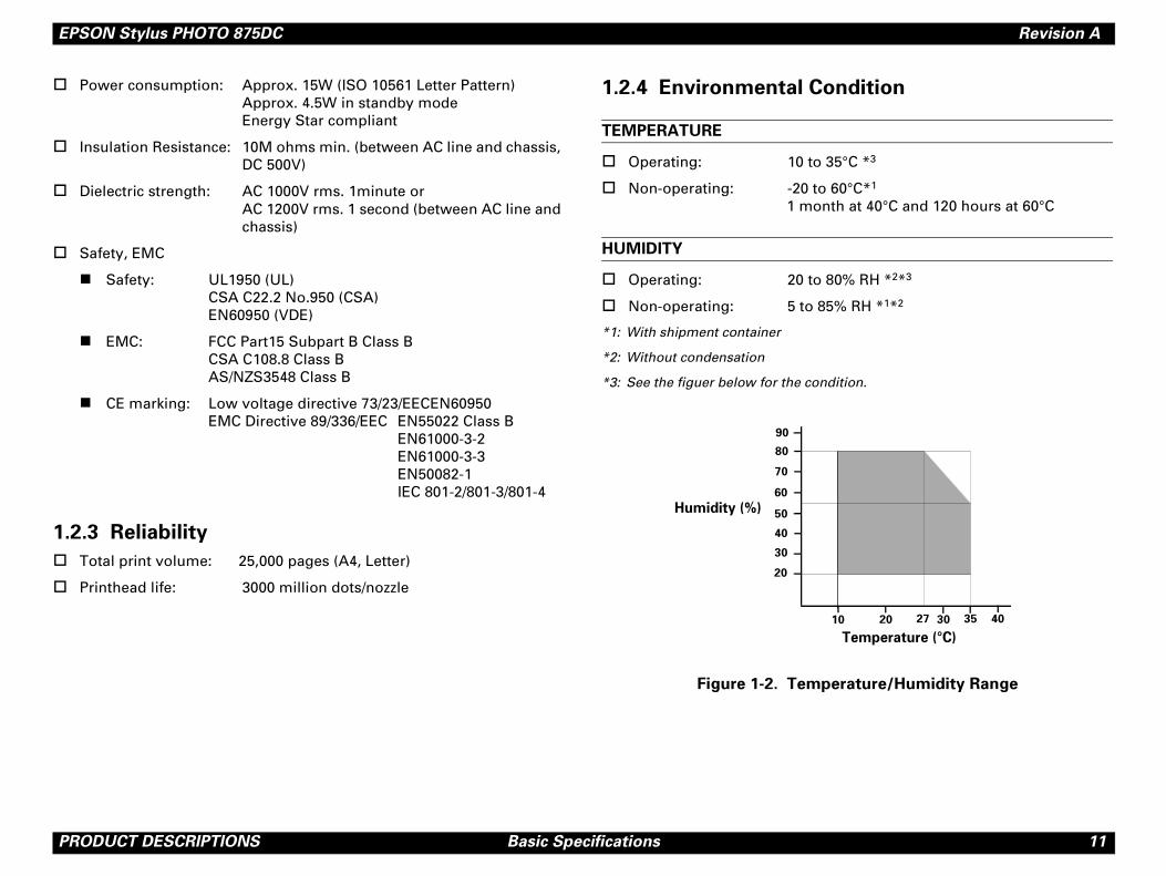
1.2.4 Environmental C
TEMPERATURE
" Operating: 10 t
" Non-operating: -20 1 m
HUMIDITY
" Operating: 20 t
" Non-operating: 5 to
*1: With shipment container
*2: Without condensation
*3: See the figuer below for the c
Figure 1-2. Tem
20
30
40
50
90
80
70
60
Humidity (%)
EPSON Stylus PHOTO 875DC Revision A
P 12
RE
"
"
RE
"
"
�
RODUCT DESCRIPTIONS Basic Specifications
SISTANCE TO SHOCK
Operating: 1G, within 1 ms, X, Y, Z directions
Non-operating: 2G, within 2 ms, X, Y, Z directions with shipment contanier
SISTANCE TO VIBRATION
Operating: 0.15G, 10 - 55Hz, X, Y, Z directions
Non-operating: 0.50G, 10 - 55Hz, X, Y, Z directions with shipment contanier
� � � � � �! When storing the printer, make sure the printhead is
capped.
! When transporting the printer, ensure the ink cartridges
are installed in the printer and the printhead is capped.
! If the printer power is off with the printhead left
uncapped, turn the printer on with the ink cartridges
installed, cap the printhead, and turn the printer off.
! Ink freezes at below -4°C. It will be usable again after
keeping it for about three hours at 25°C.
EPSON Stylus PHOTO 875DC Revision A
P 13
1.
1.
SP
"
"
"
"
"
CO
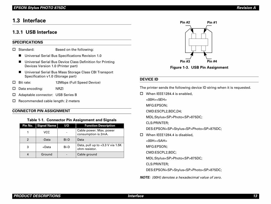
USB Pin Assignment
g device ID string when it is requested.
d,
>875DC;
P>Photo<SP>875DC;
ed,
>875DC;
P>Photo<SP>875DC;
ecimal value of zero.
Pin #1
Pin #4
RODUCT DESCRIPTIONS Interface
3 Interface
3.1 USB Interface
ECIFICATIONS
Standard: Based on the following:
! Universal Serial Bus Specifications Revision 1.0
! Universal Serial Bus Device Class Definition for PrintingDevices Version 1.0 (Printer part)
! Universal Serial Bus Mass Storage Class CBI Transport Specification v1.0 (Storage part)
Bit rate: 12Mbps (Full Speed Device)
Data encoding: NRZI
Adaptable connector: USB Series B
Recommended cable length: 2 meters
NNECTOR PIN ASSIGNMENT
Figure 1-3.
DEVICE ID
The printer sends the followin
" When IEEE1284.4 is enable
<00H><5EH>
MFG:EPSON;
CMD:ESCPL2,BDC,D4;
MDL:Stylus<SP>Photo<SP
CLS:PRINTER;
DES:EPSON<SP>Stylus<S
" When IEEE1284.4 is disabl
<00H><5AH>
MFG:EPSON;
CMD:ESCPL2,BDC;
MDL:Stylus<SP>Photo<SP
CLS:PRINTER;
DES:EPSON<SP>Stylus<S
NOTE: [00H] denotes a hexad
Table 1-1. Connector Pin Assignment and Signals
Pin No. Signal Name I/O Function Description
1 VCC -Cable power. Max. power consumption is 2mA.
2 -Data Bi-D Data
3 +Data Bi-DData, pull up to +3.3 V via 1.5K ohm resistor.
4 Ground - Cable ground
Pin #3
Pin #2
EPSON Stylus PHOTO 875DC Revision A
P 14
1.
CA
"
"
M
Th
"
"
"
"
VO
Th
"
"
"
Y Memory Stick>
(the LOCK notch) of the memory stick main
to the memory stick PCMCIA adapter
ass Storage driver is canceled.
e file”, “format”) from the host
rementioned conditions were occurs.
n it wrote data in the media with both wever, all the processing fail actually. ed, in the case that it is worst.
at the combination of the memory stick onforming to the specifications of PCMCIA. cally even if the memory stick is set up to CIA is the possibility specification that edia of “write protect” electrically.
emory stick, the following faulty occurs.
triction on use exists.
RODUCT DESCRIPTIONS Interface
3.2 PCMCIA Card Slot
RD SLOT STANDARD
PCMCIA Type-II card slot x 1
PC Card Standard (’97) compliance
EMORY CARD
e following memory card is supported.
PCMCIA Flash ATA card
Compact Flash (with PCMCIA adapter)
Smart Media (with PCMCIA adapter)
Memory Stick (with PCMCIA adapter)
LTAGE
e following voltage is supported.
5v
3.3v/5v
3.3v
<Restriction item of SON
FAULTY CONDITION
1. Carry out the light protect body.
2. Memory stick is connected(MSAC-PC1/MSAC-PC2).
3. Write protect of the USB M
4. Write data (includes “delet(Windows98, Macintosh).
NOTE: In the case that four afoincluded, all the faulty
PHENOMENON
Processing ends normally wheWIndows98 and Macintosh. HoAlso, the blue screen is display
CAUSE
The cause of this problem is thand PCMCIA adapter are not cIt is not able to detect it electri“write protect”, although PCMdetect whether or not is the m
� � � � � � � As for the SONY m
Therefore, the res
EPSON Stylus PHOTO 875DC Revision A
P 15
1.
FoMa
1.
LE
"
NO
IN
"
ver Function (Windows)
to OS as the removable disk drive, and its
acquisition
rtion condition of the PCMCIA card from e application software of it. Information ulk transfer when API is called.
sition
cquire drive name assigned for the card Also, if multiple cared readers exist on can acquire each pair of serial number and
anguage
y of OS (Japanese, English, French, Italian, ).
] function
ected (default), the driver operates the der as the “Write Protect”.
de] function
orted in [Write to Disk mode].
me (8+3 characters or more)
nly the logic format by OS)
RODUCT DESCRIPTIONS Function
4 Function
r the printer operation, please see the Stylus PHOTO 870/1270 Service nual.
4.1 Card Reader Part Panel Operation
VER
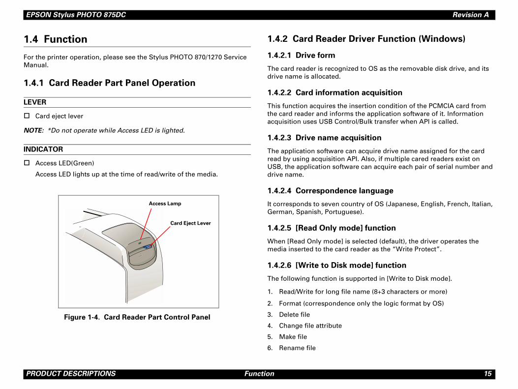
Card eject lever
TE: *Do not operate while Access LED is lighted.
DICATOR
Access LED(Green)
Access LED lights up at the time of read/write of the media.
Figure 1-4. Card Reader Part Control Panel
1.4.2 Card Reader Dri
1.4.2.1 Drive form
The card reader is recognized drive name is allocated.
1.4.2.2 Card information
This function acquires the insethe card reader and informs thacquisition uses USB Control/B
1.4.2.3 Drive name acqui
The application software can aread by using acquisition API. USB, the application software drive name.
1.4.2.4 Correspondence l
It corresponds to seven countrGerman, Spanish, Portuguese
1.4.2.5 [Read Only mode
When [Read Only mode] is selmedia inserted to the card rea
1.4.2.6 [Write to Disk mo
The following function is supp
1. Read/Write for long file na
2. Format (correspondence o
3. Delete file
4. Change file attribute
5. Make file
6. Rename file
Access Lamp
Card Eject Lever
EPSON Stylus PHOTO 875DC Revision A
P 16
7.
8.
9.
1.4
"
"
"
"
"
1.
ThTh
1.
2.
1.
Th
1.
2.
ver Function (Macintosh)
to OS as the removable disk drive.
acquisition
rtion condition of the PCMCIA card from the application software of it. Information ulk transfer when API is called.
acquisition
cquire the following information regarding PI.
r
Reader
ers exist on USB, the application software rial number and disk name.
acquisition
cquire the following information regarding PI.
nufacturer strings (product maker)
duct strings (product name)
rialNumber strings (serial number)
anguage
ge of OS (Japanese, English, French, uguese).
RODUCT DESCRIPTIONS Function
Make folder
Delete folder
Rename folder
.2.7 Switching to [Write to Disk mode]
Switching between [Read Only mode] and [Write to Disk mode] is bidirectionally possible.
Switching between the [Read Only mode] and [Write to Disk mode] is implemented in condition without a media being inserted. Mode change is carried out by executing the application software “EPSON USB RW Switcher”. The result comes into effect at the time of the next media insertion.
Since the [Read Only mode] driver and [Write to Disk mode] driver are the same driver, installation is unnecessary.
The mode information is preserved to Windows Registry. Mode change is done by referring to the registry when the host is powered on.
Registry entry that controls this mode is as follows.
HKEY_LOCAL_MACHINE¥Enum¥ESDI¥EPSON___PM800DCSTORAGE
The key is as follows:
Readonly (Binary, 00 = [Write to Disk mode], 01 = [Read Only mode])
4.2.8 USB Descriptor change function
is function rewrites USB Descriptor of the card reader by using the API. e item that rewrites is as follows.
iProduct strings (UNICODE, maximum 23 characters)
iSerialNumber strings (UNICODE, maximum 12 characters)
4.2.9 Correspondence file system
e file system that corresponds is as follows.
FAT (VFAT)
FAT32
1.4.3 Card Reader Dri
1.4.3.1 Drive form
The card reader is recognized
1.4.3.2 Card information
This function acquires the insethe card reader and can notifyacquisition uses USB Control/B
1.4.3.3 Disk information
The application software can athe card reader by using the A
1. Volume Reference Numbe
2. Driver Reference Number
3. Volume Name
4. Serial Number of the Card
Also, when multiple card readcan acquire each pair of the se
1.4.3.4 Drive information
The application software can athe card reader by using the A
1. Write Protect Status
2. USB String descriptor, iMa
3. USB String descriptor, iPro
4. USB String descriptor, iSe
1.4.3.5 Correspondence l
It corresponds to seven languaItalian, German, Spanish, Port
EPSON Stylus PHOTO 875DC Revision A
P 17
1.4
Whme
1.4
Th
1.
2.
3.
4.
5.
6.
7.
8.
9.
10
NO
1.4
"
"
"
"
removal
(untitled, etc.) are displayed on the media is inserted into the card reader.
s removed, the disk should be un-mounted on the desktop in the garbage can, or Click
arried out normally, the message “The ved from the card drive. Please remove the d and the icon disappears from the desktop.
t media is removed without un-mounting,
essage is displayed immediately. At this
e media in the drive immediately. There is
that the system becomes unstable and the
he media is not replaced in the drive.
t USB cable is pulled out without un-
warning message is displayed
t this time, reconnect the cable to the port
here is the possibility that the system
ble and also the data be lost if the cable is
d to the port.
RODUCT DESCRIPTIONS Function
.3.6 [Read Only mode] function
en [Read Only mode] is selected (default), the driver operates the dia that is inserted to the card reader as the “Write Protect”.
.3.7 [Write to Disk mode] function
e following function is supported in [Write to Disk mode].
Read/Write for long file name (8+3 characters or more)
Format
Delete file
Change file attribute
Make file
Rename file
Make folder
Delete folder
Rename folder
. Memory of the Folder condition (location, size etc)*
TE: Not able to acquire the information that is whether the file is opened by the restriction of File Exchange of the MacOS 8.5.1 belonging.
.3.8 Switching to [Write to Disk mode]
Switching between [Read Only mode] and [Write to Disk mode] is bidirectionally possible.
Mode change is implemented in condition without the media being mounted. The mode change is carried out by the implementation of the application software “EPSON USB RW Switcher”.
The change result comes into effect at the time of the next media mounting.
The mode information is stored to the initial setting file (EPSON PhotoStarter pref).
1.4.3.9 Media insertion /
" The icon and volume namedesktop when the PCMCIA
" In the case that the media iwithout fail. (Drag the icon[Eject] on [Special] menu.)
" When the un-mounting is cmemory card can be remomemory card.” is displaye
� � � � � � �! In the case tha
the warning m
time, replace th
the possibility
data be lost if t
! In the case tha
mounting, the
immediately. A
immediately. T
becomes unsta
not reconnecte
EPSON Stylus PHOTO 875DC Revision A
P 18
1.4
Meforcu
1.4
Anexme
1.
1.
2.
3.
*:
pansion manager
is selected by the expansion manager, the displayed as an item information.
geClass1
necessary to use the to series PCMCIA card
RODUCT DESCRIPTIONS Function
.3.10 Media format
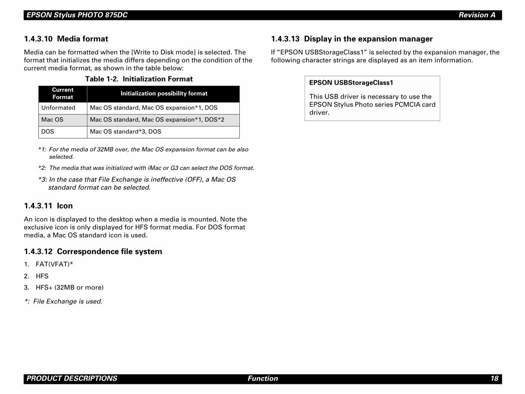
dia can be formatted when the [Write to Disk mode] is selected. The mat that initializes the media differs depending on the condition of the rrent media format, as shown in the table below:
*1: For the media of 32MB over, the Mac OS expansion format can be also selected.
*2: The media that was initialized with iMac or G3 can select the DOS format.
*3: In the case that File Exchange is ineffective (OFF), a Mac OS standard format can be selected.
.3.11 Icon
icon is displayed to the desktop when a media is mounted. Note the clusive icon is only displayed for HFS format media. For DOS format dia, a Mac OS standard icon is used.
4.3.12 Correspondence file system
FAT(VFAT)*
HFS
HFS+ (32MB or more)
File Exchange is used.
1.4.3.13 Display in the ex
If “EPSON USBStorageClass1”following character strings are
Table 1-2. Initialization Format
Current
Format Initialization possibility format
Unformated Mac OS standard, Mac OS expansion*1, DOS
Mac OS Mac OS standard, Mac OS expansion*1, DOS*2
DOS Mac OS standard*3, DOS
EPSON USBStora
This USB driver isEPSON Stylus Phodriver.
EPSON Stylus PHOTO 875DC Revision A
P 19
1.
DI
"
"
NO
W
Ap
RODUCT DESCRIPTIONS Outer Case Specifications
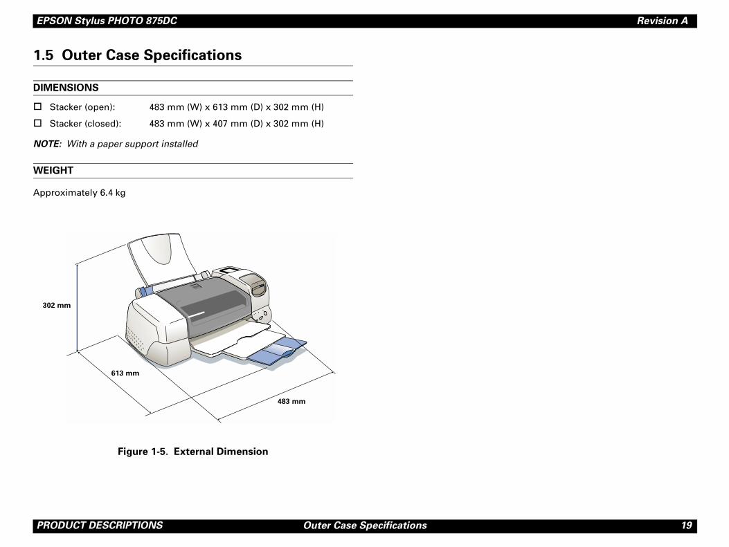
5 Outer Case Specifications
MENSIONS
Stacker (open): 483 mm (W) x 613 mm (D) x 302 mm (H)
Stacker (closed): 483 mm (W) x 407 mm (D) x 302 mm (H)
TE: With a paper support installed
EIGHT
proximately 6.4 kg
Figure 1-5. External Dimension
302 mm
613 mm
483 mm

C H A P T E R
2OP TING PRINCIPLES
ERA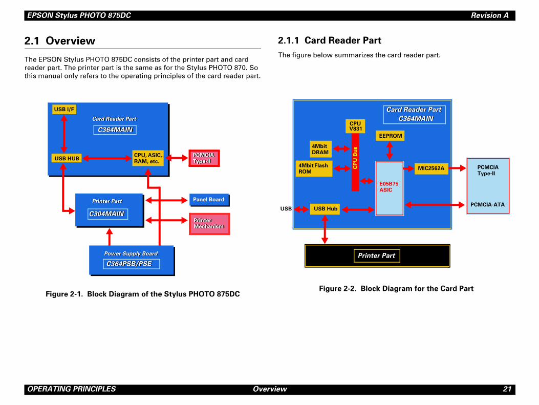
EPSON Stylus PHOTO 875DC Revision A
O 21
2.
Threathi
t
the card reader part.
k Diagram for the Card Part
PCMCIA-ATA
er Part
EEPROM
E05B75ASIC
PCMCIA Type-II
r Part
Card Reader PartCard Reader Part
C364MAINC364MAIN
MIC2562A
PERATING PRINCIPLES Overview
1 Overview
e EPSON Stylus PHOTO 875DC consists of the printer part and card der part. The printer part is the same as for the Stylus PHOTO 870. So
s manual only refers to the operating principles of the card reader part.
Figure 2-1. Block Diagram of the Stylus PHOTO 875DC
2.1.1 Card Reader Par
The figure below summarizes
Figure 2-2. Bloc
Printer PartPrinter Part
Card Reader PartCard Reader Part
Panel Board
C304MAIN
USB I/F
CPU, ASIC, RAM, etc.
USB HUB
Panel Board
Printer Mechanism
C364MAINC364MAIN
PCMCIA Type-IIPCMCIA Type-II
C304MAINPrinter Mechanism
Power Supply Board
C364PSB/PSEC364PSB/PSE
Power Supply Board
USB
CPUV831
4Mbit DRAM
USB Hub
4Mbit Flash ROM
CP
U B
us
Printe
EPSON Stylus PHOTO 875DC Revision A
O 22
Thtab
C
A(E
M
M0
M5
A1
b ICTQFPperative self power modetes a transceiver that complies with the sal serial bus specifications Rev.1.
s in the Card Reader Part (continued)
Functions
PERATING PRINCIPLES Overview
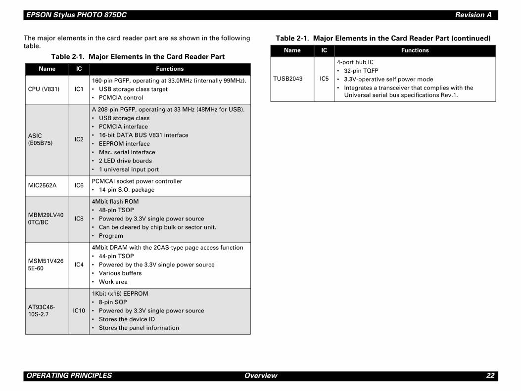
e major elements in the card reader part are as shown in the following le.
Table 2-1. Major Elements in the Card Reader Part
Name IC Functions
PU (V831) IC1160-pin PGFP, operating at 33.0MHz (internally 99MHz).• USB storage class target• PCMCIA control
SIC 05B75)
IC2
A 208-pin PGFP, operating at 33 MHz (48MHz for USB).• USB storage class• PCMCIA interface• 16-bit DATA BUS V831 interface• EEPROM interface• Mac. serial interface• 2 LED drive boards• 1 universal input port
IC2562A IC6PCMCAI socket power controller• 14-pin S.O. package
BM29LV40TC/BC
IC8
4Mbit flash ROM• 48-pin TSOP• Powered by 3.3V single power source• Can be cleared by chip bulk or sector unit.• Program
SM51V426E-60
IC4
4Mbit DRAM with the 2CAS-type page access function• 44-pin TSOP• Powered by the 3.3V single power source• Various buffers• Work area
T93C46-0S-2.7
IC10
1Kbit (x16) EEPROM• 8-pin SOP• Powered by 3.3V single power source• Stores the device ID• Stores the panel information
TUSB2043 IC5
4-port hu• 32-pin • 3.3V-o• Integra
Univer
Table 2-1. Major Element
Name IC
EPSON Stylus PHOTO 875DC Revision A
O 23
2.
C3fol
"
"
"
tures the following:
al serial bus specifications Rev. 1.0.
s.
down stream ports. (Other two are not
out CPU’s control
ilt up to allow future support availability.
ion
the hub IC (TUSB2043A) lets the printer owing order:
PERATING PRINCIPLES Overview
1.2 Power Supply Board
64PSB/PSE, the power supply board of this printer, features the lowing:
Logic line: +5V ± 5%, 0.95A+3.3V ± 5%, 0.85A
Drive line: +42V ± 5%, 0.4A (maximum 1.4A)
Power supply control in the secondary power switch
! The secondary side switching operation allows the printer to keep supplying power to the both logic and drive lines for at least 30 seconds after the printer power is turned off.
! If the AC plug is disconnected from the AC socket while the printer power is on, voltage for the logic line is kept for at least 256ms.
2.1.3 USB Hub
2.1.3.1 Overview
The USB hub of this printer fea
" Complies with the Univers
" Not powered from the Vbu
" Self-powered hub
" Two ports are used as the used.)
" Stand-alone type hub with
" Vendor ID/product ID is bu
2.1.3.2 Hub Port Connect
When connecting to the USB, recognize the device in the foll
1. Hub IC
2. Printer part
3. Card reader part
EPSON Stylus PHOTO 875DC Revision A
O 24
2.
ThPH
circuit
CR motor driver circuit
it A)
circuit
r circuit
alent)
t )
PF motor driver circuit
l circuit
circuit
CR motor driver circuit
it )
circuit
r circuit
USB I/F
lent)
t )
PF motor driver circuit
Mini USB connector
"
"
"
Block Diagram
circuit
PERATING PRINCIPLES Overview
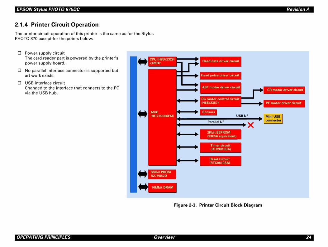
1.4 Printer Circuit Operation
e printer circuit operation of this printer is the same as for the Stylus OTO 870 except for the points below:
Head data driver
Timer circu(RTC9810S
Head pulse driver
Sensors
8Mbit PROM R27V852D
16Mbit DRAM
ASF motor drive
2Kbit EEPROM(93C56 equiv
Reset Circui(RTC9810SA
CPU (H8S/2328) 24MHz
DC motor contro(H8S/2357)
Head data driver
Timer circu(RTC9810SA
Head pulse driver
Sensors
8Mbit PROM R27V852D
16Mbit DRAM
ASF motor drive
Parallel I/F
2Kbit EEPROM(93C56 equiva
Reset Circui(RTC9810SA
ASIC (HG73C066FM)
CPU (H8S/2328) 24MHz
Power supply circuitThe card reader part is powered by the printer’s power supply board.
No parallel interface connector is supported but art work exists.
USB interface circuitChanged to the interface that connects to the PC via the USB hub.
Figure 2-3. Printer Circuit
DC motor control(H8S/2357)
C H A P T E R
3T BLESHOOTING
ROU
EPSON Stylus PHOTO 875DC Revision A
T 26
3.
Ple
ROUBLESHOOTING Overview
1 Overview
ase see the EPSON Stylus PHOTO 870/1270 Service Manual.

C H A P T E R
4DISAS BLY AND ASSEMBLY
SEM
EPSON Stylus PHOTO 875DC Revision A
D 28
4.
ThcosprevareproPOde
SinonFoSe
isassembling the Printer
er the heading “WARNING” and en disassembling or assembling EPSON
power cable before disassembling or
printer.
e goggles to protect your eyes from ink. If
r eye, flush the eye with fresh water and
mediately.
to contact with your skin, wash it off with
r. If irritation occurs, contact a physician.
ry is installed on the main board of this
e to observe the following instructions
he battery:
attery away from any metal or other
that electrodes of the opposite polarity
e in contact with each other.
t the battery or put it near fire.
er on any part of the battery. (Doing so
in leakage of electrolyte from the battery,
explosion. The leakage may affect other
se to the battery.)
rge the battery. (An explosion may be
inside the battery, and cause burning or
antle the battery. (The gas inside the
y hurt your throat. Leakage, burning or
ay also be resulted.)
all the battery in the wrong direction.
ause burning or explosion.)
osion if the battery is incorrectly replaced.
ith the same or equivalent type
by the manufacture. Dispose the used
ding to government’s law and
ISASSEMBLY AND ASSEMBLY Overview
1 Overview
is chapter describes procedures for disassembling the main mponents of the EPSON Stylus PHOTO 875DC. Unless otherwise ecified, disassembly units or components can be reassembled by ersing the disassembly procedure. Therefore, no assembly procedures included in this chapter. Precautions for any disassembly or assembly cedure are described under the heading “CAUTION” and “CHECK INT”. Any adjustments required after disassembling the units are scribed under the heading “REQUIRED ADJUSTMENT”.
ce the printer part is common to the Stylus PHOTO 870, this manual ly describes the procedures that are specific to Stylus PHOTO 875DC. r the rest of the procedures, please see the Stylus PHOTO 870/1270 rvice Manual.
4.1.1 Precaution for D
See the precautions given und“CAUTION” in this section whStylus PHOTO 875DC.
� � � � � ! Disconnect the
assembling the
! Wear protectiv
ink gets in you
see a doctor im
! If ink comes in
soap and wate
! A lithium batte
printer. Be sur
when serving t
1. Keep the b
batteries so
do not com
2. Do not hea
3. Do not sold
may result
burning or
devices clo
4. Do not cha
generated
explosion.)
5. Do not dism
battery ma
explosion m
6. Do not inst
(This may c
! Danger of expl
Replace only w
recommended
batteries accor
regulations.
EPSON Stylus PHOTO 875DC Revision A
D 29
mended for disassembling, assembling, or tools that meet these specifications.
le 4-1. Tool List
Commercially
AvailableCode
O.K. B743800200
O.K. B743800400
O.K. B741000100
O.K. B741700100
SON exclusive 1050767
SON exclusive 1051765
ISASSEMBLY AND ASSEMBLY Overview
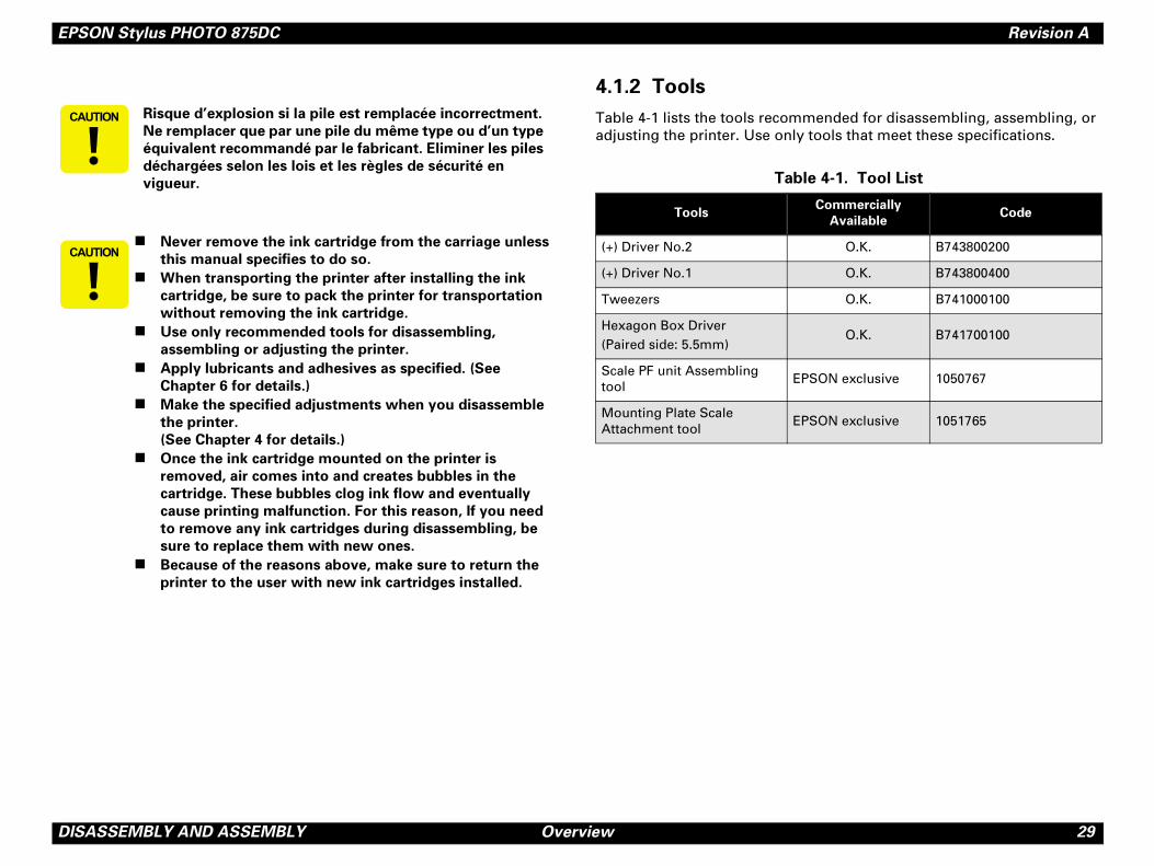
4.1.2 Tools
Table 4-1 lists the tools recomadjusting the printer. Use only
� � � � � � � Risque d’explosion si la pile est remplacée incorrectment.
Ne remplacer que par une pile du même type ou d’un type
équivalent recommandé par le fabricant. Eliminer les piles
déchargées selon les lois et les règles de sécurité en
vigueur.
� � � � � � �! Never remove the ink cartridge from the carriage unless
this manual specifies to do so.
! When transporting the printer after installing the ink
cartridge, be sure to pack the printer for transportation
without removing the ink cartridge.
! Use only recommended tools for disassembling,
assembling or adjusting the printer.
! Apply lubricants and adhesives as specified. (See
Chapter 6 for details.)
! Make the specified adjustments when you disassemble
the printer.
(See Chapter 4 for details.)
! Once the ink cartridge mounted on the printer is
removed, air comes into and creates bubbles in the
cartridge. These bubbles clog ink flow and eventually
cause printing malfunction. For this reason, If you need
to remove any ink cartridges during disassembling, be
sure to replace them with new ones.
! Because of the reasons above, make sure to return the
printer to the user with new ink cartridges installed.
Tab
Tools
(+) Driver No.2
(+) Driver No.1
Tweezers
Hexagon Box Driver(Paired side: 5.5mm)
Scale PF unit Assembling tool
EP
Mounting Plate Scale Attachment tool
EP
EPSON Stylus PHOTO 875DC Revision A
D 30
4.
Tamaref
ISASSEMBLY AND ASSEMBLY Overview
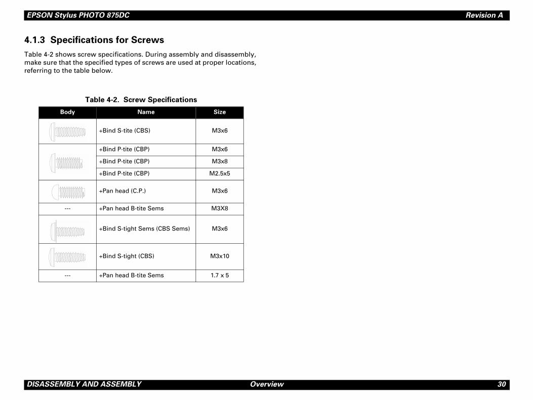
1.3 Specifications for Screws
ble 4-2 shows screw specifications. During assembly and disassembly, ke sure that the specified types of screws are used at proper locations, erring to the table below.
Table 4-2. Screw Specifications
Body Name Size
+Bind S-tite (CBS) M3x6
+Bind P-tite (CBP) M3x6
+Bind P-tite (CBP) M3x8
+Bind P-tite (CBP) M2.5x5
+Pan head (C.P.) M3x6
--- +Pan head B-tite Sems M3X8
+Bind S-tight Sems (CBS Sems) M3x6
+Bind S-tight (CBS) M3x10
--- +Pan head B-tite Sems 1.7 x 5
EPSON Stylus PHOTO 875DC Revision A
D 31
4.
Bewheff
Is Check Required?
ecked / "Not necessary
ecked / "Not necessary
ecked / "Not necessary
ecked / "Not necessary
ecked / "Not necessary
ecked / "Not necessary
ecked / "Not necessary
ecked / "Not necessary
ecked / "Not necessary
ecked / "Not necessary
ecked / "Not necessary
ecked / "Not necessary
ecked / "Not necessary
ecked / "Not necessary
ecked / "Not necessary
ecked / "Not necessary
ecked / "Not necessary
ecked / "Not necessary
ecked / "Not necessary
ecked / "Not necessary
ecked / "Not necessary
ISASSEMBLY AND ASSEMBLY Overview
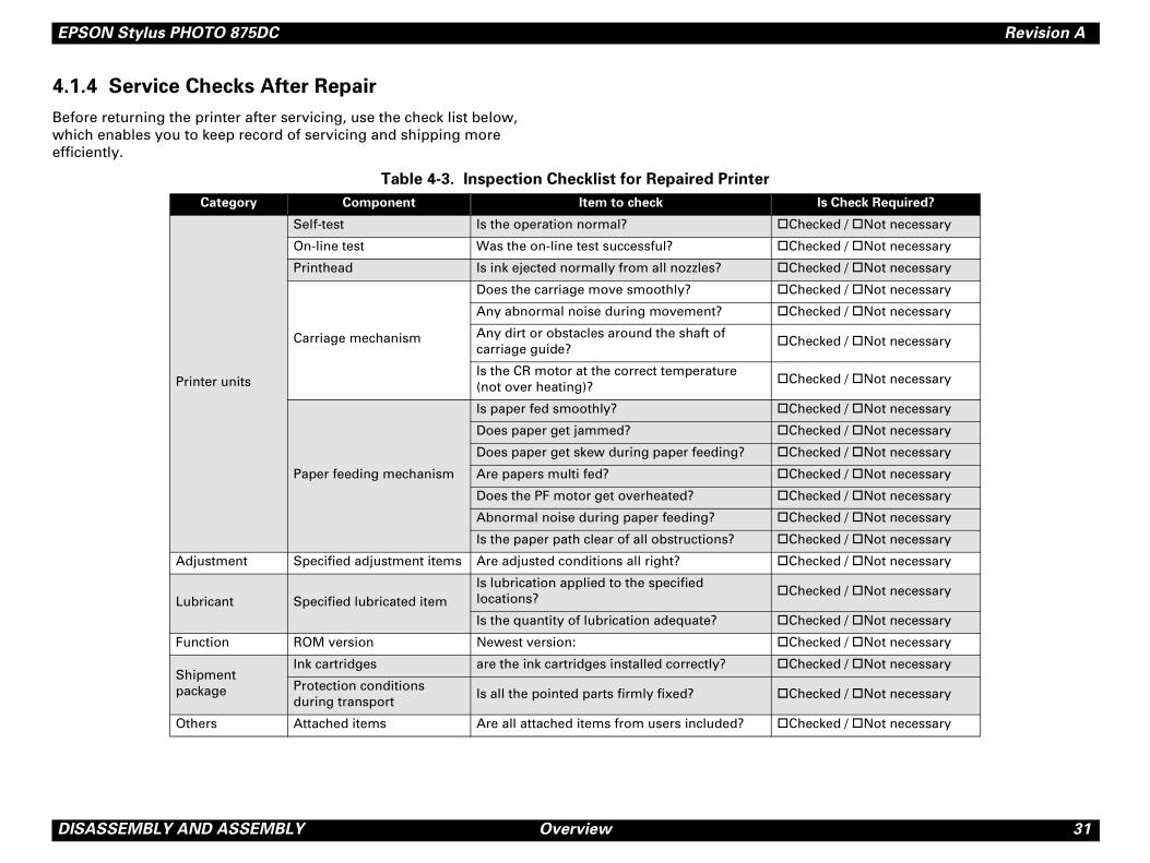
1.4 Service Checks After Repair
fore returning the printer after servicing, use the check list below, ich enables you to keep record of servicing and shipping more iciently.
Table 4-3. Inspection Checklist for Repaired Printer
Category Component Item to check
Printer units
Self-test Is the operation normal? "Ch
On-line test Was the on-line test successful? "Ch
Printhead Is ink ejected normally from all nozzles? "Ch
Carriage mechanism
Does the carriage move smoothly? "Ch
Any abnormal noise during movement? "Ch
Any dirt or obstacles around the shaft of carriage guide?
"Ch
Is the CR motor at the correct temperature (not over heating)?
"Ch
Paper feeding mechanism
Is paper fed smoothly? "Ch
Does paper get jammed? "Ch
Does paper get skew during paper feeding? "Ch
Are papers multi fed? "Ch
Does the PF motor get overheated? "Ch
Abnormal noise during paper feeding? "Ch
Is the paper path clear of all obstructions? "Ch
Adjustment Specified adjustment items Are adjusted conditions all right? "Ch
Lubricant Specified lubricated itemIs lubrication applied to the specified locations?
"Ch
Is the quantity of lubrication adequate? "Ch
Function ROM version Newest version: "Ch
Shipment package
Ink cartridges are the ink cartridges installed correctly? "Ch
Protection conditions during transport
Is all the pointed parts firmly fixed? "Ch
Others Attached items Are all attached items from users included? "Ch
EPSON Stylus PHOTO 875DC Revision A
D 32
4.
Th
ISASSEMBLY AND ASSEMBLY Disassembly Procedures
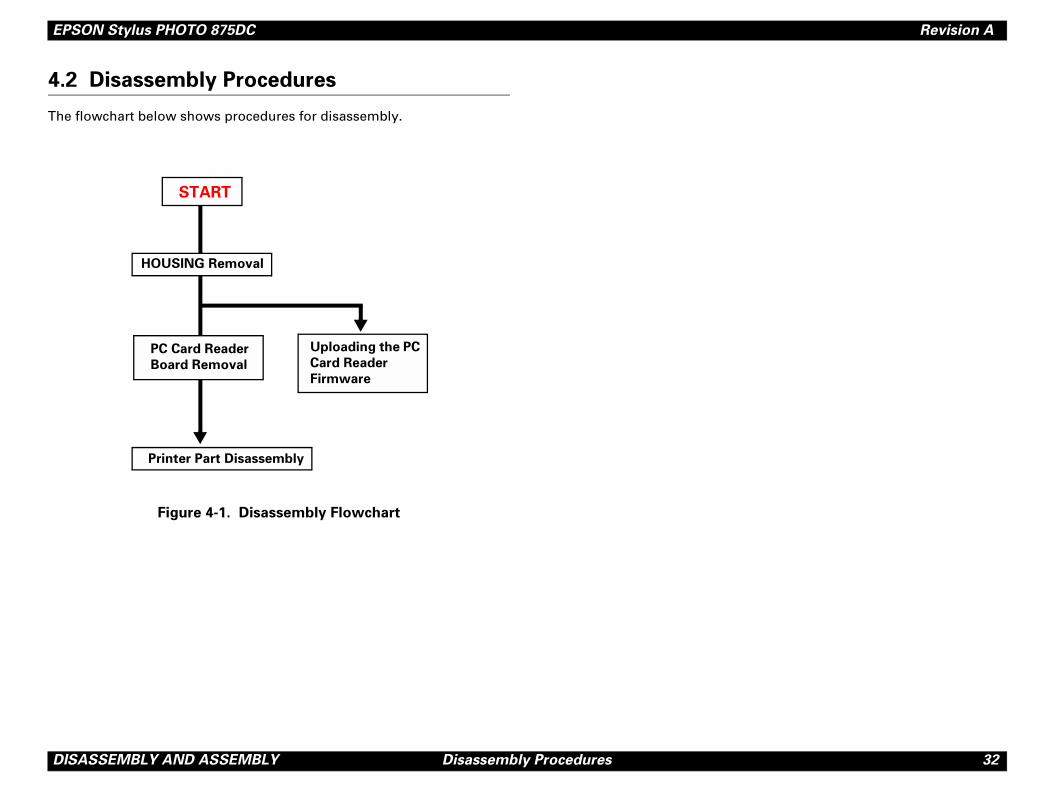
2 Disassembly Procedures
e flowchart below shows procedures for disassembly.
Figure 4-1. Disassembly Flowchart
HOUSING Removal
PC Card Reader
Board Removal
Printer Part Disassembly
Uploading the PC
Card Reader
Firmware
START
EPSON Stylus PHOTO 875DC Revision A
D 33
4.
Sinjus
1.
2.
3.
. HOUSING Removal
dis04
HOUSING
10) Screws
CBS (3x10) Screws
ISASSEMBLY AND ASSEMBLY Disassembly Procedures
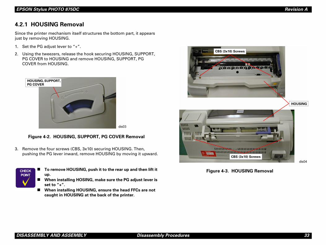
2.1 HOUSING Removal
ce the printer mechanism itself structures the bottom part, it appears t by removing HOUSING.
Set the PG adjust lever to “+”.
Using the tweezers, release the hook securing HOUSING, SUPPORT, PG COVER to HOUSING and remove HOUSING, SUPPORT, PG COVER from HOUSING.
Figure 4-2. HOUSING, SUPPORT, PG COVER Removal
Remove the four screws (CBS, 3x10) securing HOUSING. Then, pushing the PG lever inward, remove HOUSING by moving it upward.
Figure 4-3� � � �
� � � � �
! To remove HOUSING, push it to the rear up and then lift it
up.
! When installing HOSING, make sure the PG adjust lever is
set to “+”.
! When installing HOUSING, ensure the head FFCs are not
caught in HOUSING at the back of the printer.
dis03
HOUSING, SUPPORT, PG COVER
CBS (3x
EPSON Stylus PHOTO 875DC Revision A
D 34
4.
1.
2.
3.
G, SUPPORT, PC CARD Removal
�
dis05
CBS (3x6)
T, PC CARD
ISASSEMBLY AND ASSEMBLY Disassembly Procedures
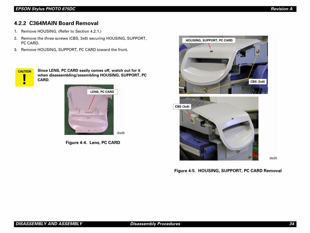
2.2 C364MAIN Board Removal
Remove HOUSING. (Refer to Section 4.2.1.)
Remove the three screws (CBS, 3x6) securing HOUSING, SUPPORT, PC CARD.
Remove HOUSING, SUPPORT, PC CARD toward the front.
Figure 4-5. HOUSIN
� � � � � � Since LENS, PC CARD easily comes off, watch out for it
when disassembling/assembling HOUSING, SUPPORT, PC
CARD.
Figure 4-4. Lens, PC CARD
dis06
LENS, PC CARD
HOUSING, SUPPOR
CBS (3x6)
EPSON Stylus PHOTO 875DC Revision A
D 35
4.
5.
for USB and C364PSB/PSE) from the IN Board.
ard.
364MAIN Board Removal
dis08
C364MAIN Board
(3x6)
ISASSEMBLY AND ASSEMBLY Disassembly Procedures
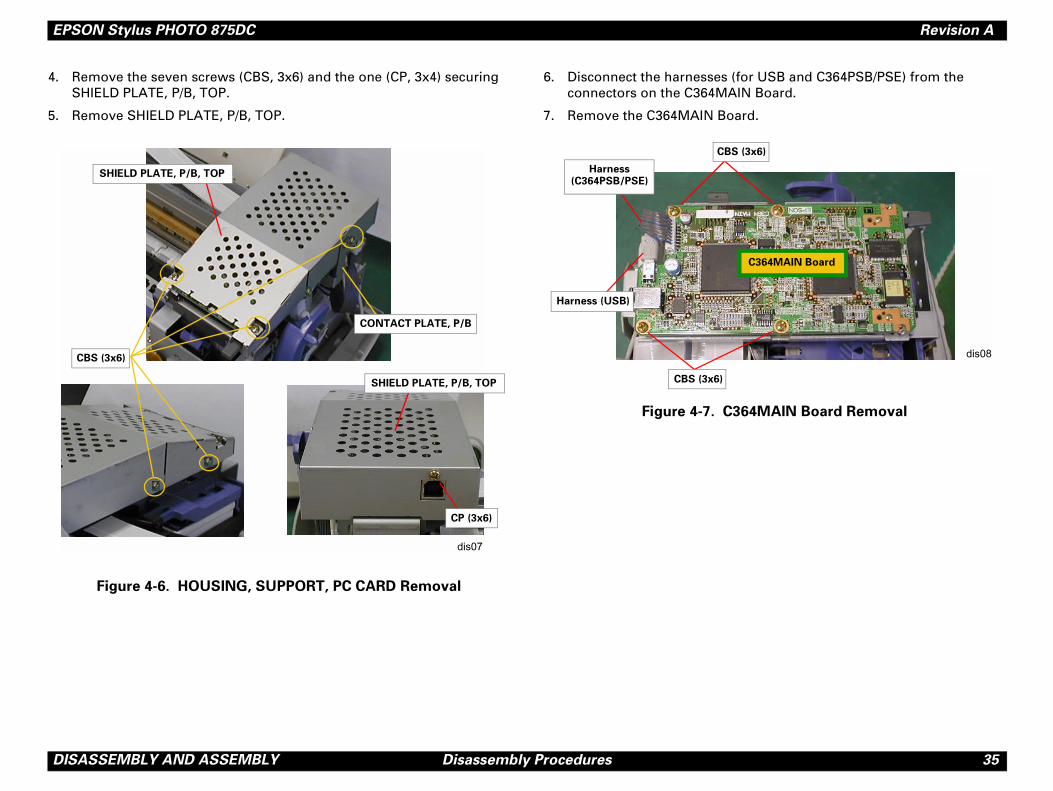
Remove the seven screws (CBS, 3x6) and the one (CP, 3x4) securing SHIELD PLATE, P/B, TOP.
Remove SHIELD PLATE, P/B, TOP.
Figure 4-6. HOUSING, SUPPORT, PC CARD Removal
6. Disconnect the harnesses (connectors on the C364MA
7. Remove the C364MAIN Bo
Figure 4-7. C
dis07
CONTACT PLATE, P/B
CBS (3x6)
SHIELD PLATE, P/B, TOP
SHIELD PLATE, P/B, TOP
CP (3x6)
CBS
CBS (3x6)
Harness (C364PSB/PSE)
Harness (USB)
EPSON Stylus PHOTO 875DC Revision A
D 36
4.
Thpa
1.
2.
3.
BS, 3x6) securing the C364MAIN Board igure 4-9.)
4MAIN Board Removal (2)
BS, 3x6) securing the panel unit to the
ing the C364MAIN Unit to the printer part el unit to the C364MAIN Unit, and remove
dis10
BS (3x6)
ISASSEMBLY AND ASSEMBLY Disassembly Procedures
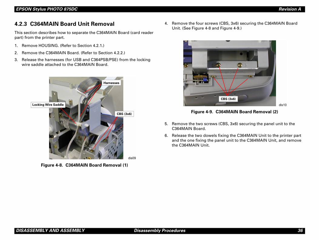
2.3 C364MAIN Board Unit Removal
is section describes how to separate the C364MAIN Board (card reader rt) from the printer part.
Remove HOUSING. (Refer to Section 4.2.1.)
Remove the C364MAIN Board. (Refer to Section 4.2.2.)
Release the harnesses (for USB and C364PSB/PSE) from the locking wire saddle attached to the C364MAIN Board.
Figure 4-8. C364MAIN Board Removal (1)
4. Remove the four screws (CUnit. (See Figure 4-8 and F
Figure 4-9. C36
5. Remove the two screws (CC364MAIN Board.
6. Release the two dowels fixand the one fixing the panthe C364MAIN Unit.
dis09
Harnesses
CBS (3x6)
Locking Wire Saddle
C

C H A P T E R
5DJUSTMENT
A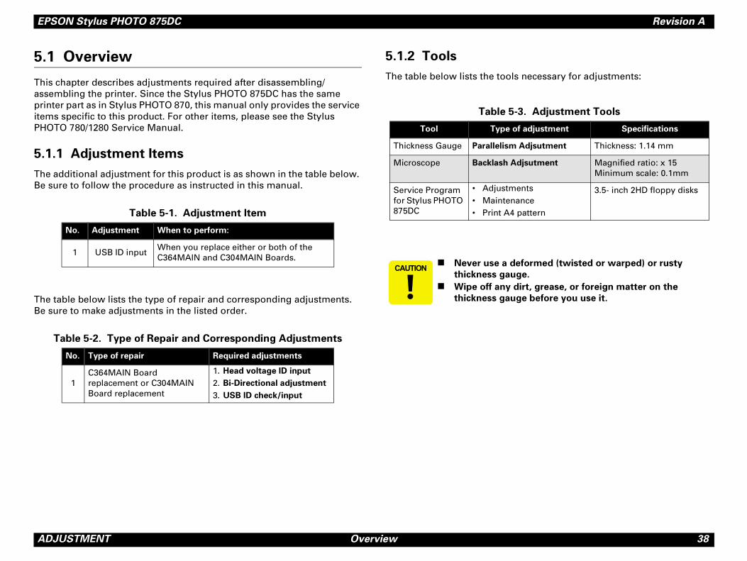
EPSON Stylus PHOTO 875DC Revision A
A 38
5.
ThaspriitePH
5.
ThBe
ThBe
necessary for adjustments:
. Adjustment Tools
adjustment Specifications
djsutment Thickness: 1.14 mm
jsutment Magnified ratio: x 15Minimum scale: 0.1mm
ntsnceattern
3.5- inch 2HD floppy disks
formed (twisted or warped) or rusty
e.
irt, grease, or foreign matter on the
e before you use it.
DJUSTMENT Overview
1 Overview
is chapter describes adjustments required after disassembling/sembling the printer. Since the Stylus PHOTO 875DC has the same nter part as in Stylus PHOTO 870, this manual only provides the service ms specific to this product. For other items, please see the Stylus OTO 780/1280 Service Manual.
1.1 Adjustment Items
e additional adjustment for this product is as shown in the table below. sure to follow the procedure as instructed in this manual.
e table below lists the type of repair and corresponding adjustments. sure to make adjustments in the listed order.
5.1.2 Tools
The table below lists the tools
Table 5-1. Adjustment Item
No. Adjustment When to perform:
1 USB ID inputWhen you replace either or both of the C364MAIN and C304MAIN Boards.
Table 5-2. Type of Repair and Corresponding Adjustments
No. Type of repair Required adjustments
1C364MAIN Board replacement or C304MAIN Board replacement
1. Head voltage ID input
2. Bi-Directional adjustment
3. USB ID check/input
Table 5-3
Tool Type of
Thickness Gauge Parallelism A
Microscope Backlash Ad
Service Program for Stylus PHOTO 875DC
• Adjustme• Maintena• Print A4 p
� � � � � � �! Never use a de
thickness gaug
! Wipe off any d
thickness gaug
EPSON Stylus PHOTO 875DC Revision A
A 39
5.
Th87
5.
Eapriyocoad
5.
Thin theprople
Program
rk properly, you have to set up your
as the printer port.
r listed below:
oppy disk drive of your computer, and then
isk2”, and the installation is done.
eated in the Adjustment Program folder to
N
run the program on Windows 98 only.
printer in a non-printing status for 5
re, the carriage automatically returns to
In this case, you need to re-boot the
art the program.
the setting for Font size in Display settings.
ect the printer to a PC with an interface
u start the program. Otherwise, the
s.
y command to the printer during a check
ce program is running, if the printer is
e interface cable is disconnected, you need
rogram again.
DJUSTMENT Adjustment
2 Adjustment
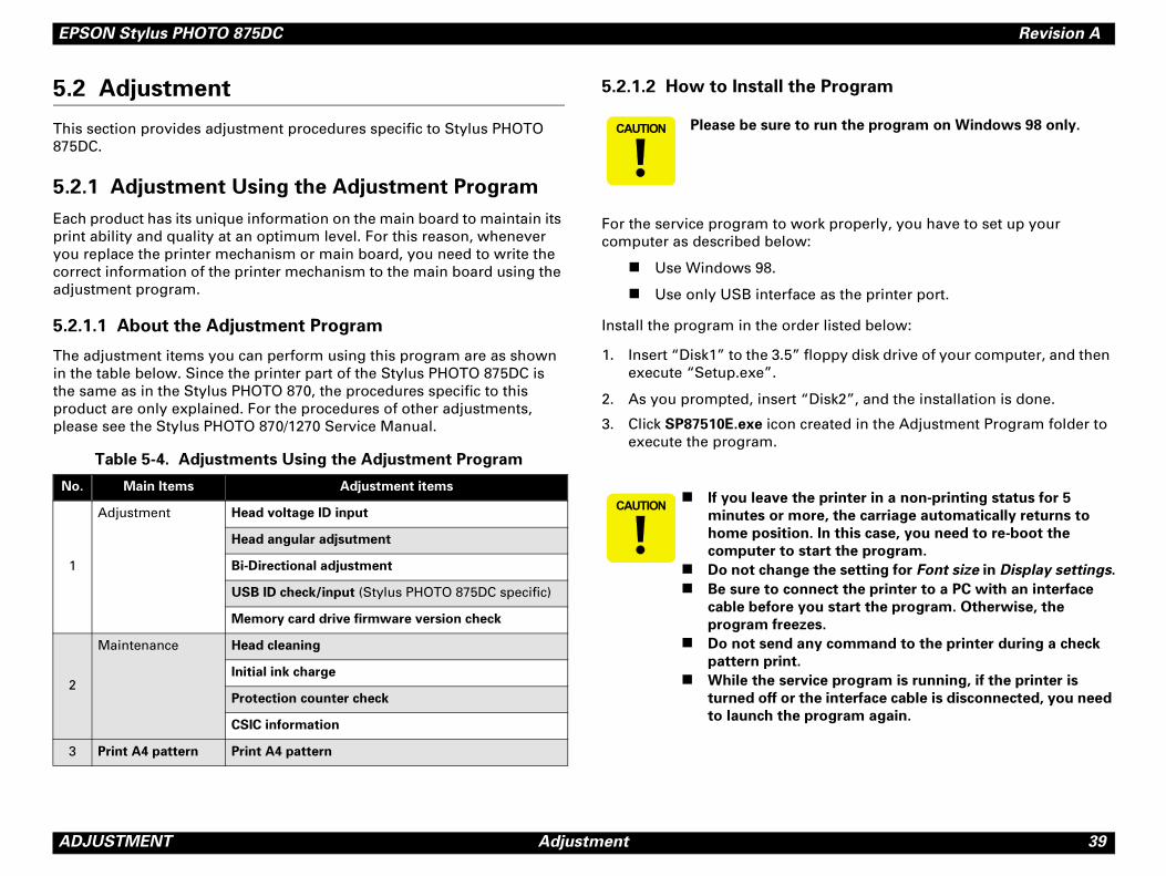
is section provides adjustment procedures specific to Stylus PHOTO 5DC.
2.1 Adjustment Using the Adjustment Program
ch product has its unique information on the main board to maintain its nt ability and quality at an optimum level. For this reason, whenever u replace the printer mechanism or main board, you need to write the rrect information of the printer mechanism to the main board using the justment program.
2.1.1 About the Adjustment Program
e adjustment items you can perform using this program are as shown the table below. Since the printer part of the Stylus PHOTO 875DC is same as in the Stylus PHOTO 870, the procedures specific to this duct are only explained. For the procedures of other adjustments, ase see the Stylus PHOTO 870/1270 Service Manual.
Table 5-4. Adjustments Using the Adjustment Program
5.2.1.2 How to Install the
For the service program to wocomputer as described below:
! Use Windows 98.
! Use only USB interface
Install the program in the orde
1. Insert “Disk1” to the 3.5” flexecute “Setup.exe”.
2. As you prompted, insert “D
3. Click SP87510E.exe icon crexecute the program.
o. Main Items Adjustment items
1
Adjustment Head voltage ID input
Head angular adjsutment
Bi-Directional adjustment
USB ID check/input (Stylus PHOTO 875DC specific)
Memory card drive firmware version check
2
Maintenance Head cleaning
Initial ink charge
Protection counter check
CSIC information
3 Print A4 pattern Print A4 pattern
� � � � � � � Please be sure to
� � � � � � �! If you leave the
minutes or mo
home position.
computer to st
! Do not change
! Be sure to conn
cable before yo
program freeze
! Do not send an
pattern print.
! While the servi
turned off or th
to launch the p
EPSON Stylus PHOTO 875DC Revision A
A 40
5.2
1.
2.
5-2. Main Menu
�
DJUSTMENT Adjustment
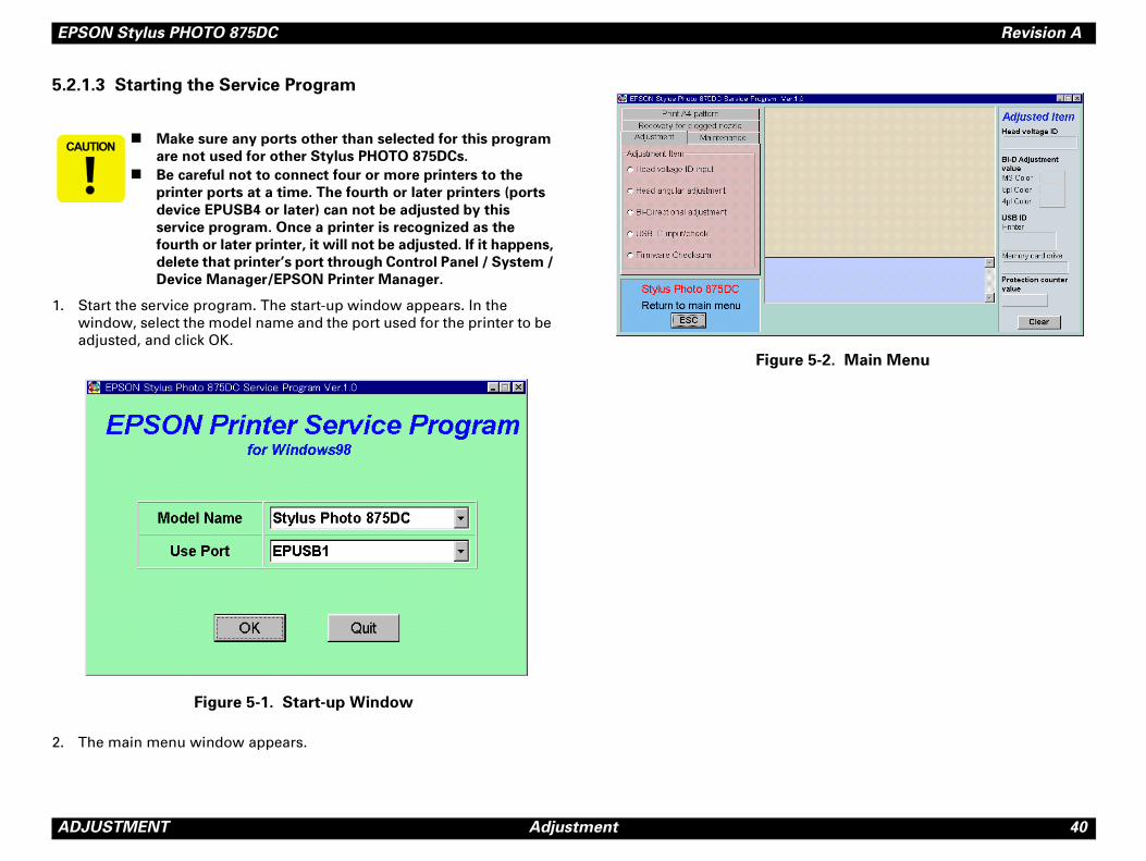
.1.3 Starting the Service Program
Start the service program. The start-up window appears. In the window, select the model name and the port used for the printer to be adjusted, and click OK.
Figure 5-1. Start-up Window
The main menu window appears.
Figure
� � � � � �! Make sure any ports other than selected for this program
are not used for other Stylus PHOTO 875DCs.
! Be careful not to connect four or more printers to the
printer ports at a time. The fourth or later printers (ports
device EPUSB4 or later) can not be adjusted by this
service program. Once a printer is recognized as the
fourth or later printer, it will not be adjusted. If it happens,
delete that printer’s port through Control Panel / System /
Device Manager/EPSON Printer Manager.
EPSON Stylus PHOTO 875DC Revision A
A 41
5.
ThpaonrefFopacoUSSopro
nd access the main menu.
and click OK. The USB ID input/check
B ID Input/Check Window
ick OK. The USB ID input window appears.
SB ID Input Window (1)
�
DJUSTMENT Adjustment
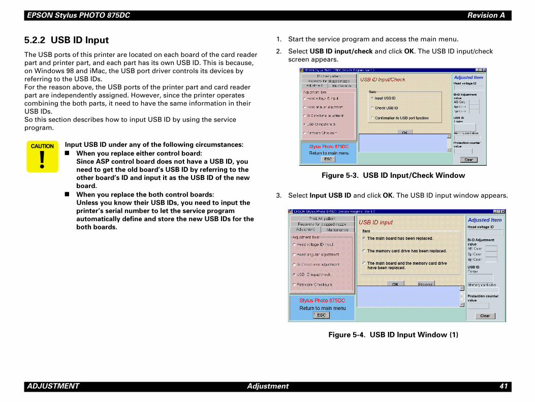
2.2 USB ID Input
e USB ports of this printer are located on each board of the card reader rt and printer part, and each part has its own USB ID. This is because, Windows 98 and iMac, the USB port driver controls its devices by erring to the USB IDs. r the reason above, the USB ports of the printer part and card reader rt are independently assigned. However, since the printer operates mbining the both parts, it need to have the same information in their B IDs. this section describes how to input USB ID by using the service gram.
1. Start the service program a
2. Select USB ID input/check
screen appears.
Figure 5-3. US
3. Select Input USB ID and cl
Figure 5-4. U
� � � � � � Input USB ID under any of the following circumstances:
! When you replace either control board:
Since ASP control board does not have a USB ID, you
need to get the old board’s USB ID by referring to the
other board’s ID and input it as the USB ID of the new
board.
! When you replace the both control boards:
Unless you know their USB IDs, you need to input the
printer’s serial number to let the service program
automatically define and store the new USB IDs for the
both boards.
EPSON Stylus PHOTO 875DC Revision A
A 42
4.
5.
6.
7.
8.
k on.
gain.
USB ID Input/Check window and click OK. d in the bottom window.
SB ID Input Window (3)
B port function and click OK, and the rt function window appears. In the B port connection is established properly,
D, be sure to quit the service program and
ower off. Otherwise, the new USB ID is
control board.
u type a wrong serial number, the service
ts it. Therefore, be sure to type the serial
.
are not effective until the printer power is
since they are stored in EEPROM when the
d off.
DJUSTMENT Adjustment
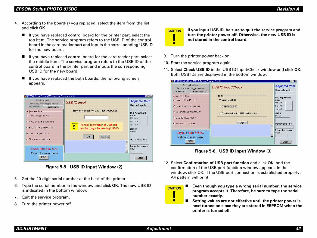
According to the board(s) you replaced, select the item from the list and click OK
! If you have replaced control board for the printer part, select the top item. The service program refers to the USB ID of the control board in the card reader part and inputs the corresponding USB ID for the new board.
! If you have replaced control board for the card reader part, select the middle item. The service program refers to the USB ID of the control board in the printer part and inputs the corresponding USB ID for the new board.
! If you have replaced the both boards, the following screen appears.
Figure 5-5. USB ID Input Window (2)
Get the 10-digit serial number at the back of the printer.
Type the serial number in the window and click OK. The new USB ID is indicated in the bottom window.
Quit the service program.
Turn the printer power off.
9. Turn the printer power bac
10. Start the service program a
11. Select Check USB ID in theBoth USB IDs are displaye
Figure 5-6. U
12. Select Confirmation of US
confirmation of the USB powindow, click OK. If the USA4 pattern will print.
� � � � � � � If you input USB I
turn the printer p
not stored in the
� � � � � � �! Even though yo
program accep
number exactly
! Setting values
next turned on
printer is turne
EPSON Stylus PHOTO 875DC Revision A
A 43
5.
Thca
5.2
Thca
"
1.
2.
3.
4.
5.
mory Card Driver Firmware
indows98 or the one that supports USB
PCMCIA card adopter or PCMCIA memory
Chapter 4/Section 4.2.1.)
P/B, Upper” for the card reader. (See
C364MAIN board as shown below:
5-7. JP2 and LED1
t stores the firmware into the PCMCIA slot ower on.
�
DJUSTMENT Adjustment
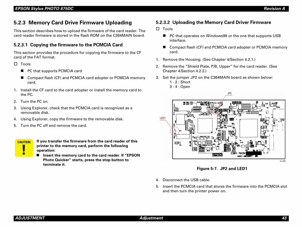
2.3 Memory Card Drive Firmware Uploading
is section describes how to upload the firmware of the card reader. The rd reader firmware is stored in the flash ROM on the C364MAIN board.
.3.1 Copying the firmware to the PCMCIA Card
is section provides the procedure for copying the firmware to the CF rd of the FAT format.
Tools
! PC that supports PCMCIA card
! Compact flash (CF) and PCMCIA card adopter or PCMCIA memory card.
Install the CF card to the card adopter or install the memory card to the PC.
Turn the PC on.
Using Explorer, check that the PCMCIA card is recognized as a removable disk.
Using Explorer, copy the firmware to the removable disk.
Turn the PC off and remove the card.
5.2.3.2 Uploading the Me
" Tools
! PC that operates on Winterface.
! Compact flash (CF) andcard.
1. Remove the Housing. (See
2. Remove the “Shield Plate,Chapter 4/Section 4.2.2.)
3. Set the jumper JP2 on the 1 - 2 : Short3 - 4 : Open
Figure
4. Disconnect the USB cable.
5. Insert the PCMCIA card thaand then turn the printer p
� � � � � � If you transfer the firmware from the card reader of this
printer to the memory card, perform the following
operation:
! Insert the memory card to the card reader. If “EPSON
Photo Quicker” starts, press the stop button to
terminate it.
EPSON Stylus PHOTO 875DC Revision A
A 44
6.
7.
8.
9.
10
emory Card Drive Firmware
he memory card drive firmware version.
nd access the main menu window.
. The Memory Card Drive Firmware s.
Drive Firmware Checksum Window
card drive firmware version is indicated.
DJUSTMENT Adjustment
Turn the printer power off. The power LED (green lamp) on the panel blinks once and the printer begins to load the firmware to the flash ROM on the card reader. When the power LED starts blinking, it means the writing is done. (It takes about ten seconds for the writing operation to be completed.)
When the operation is executed, turn the printer power off.
Set the jumper JP2 as shown below:1 - 2 : Open3 - 4 : Short
Mount the “Shield Plate, P/B, Upper” on the card reader.
. Install the Housing.
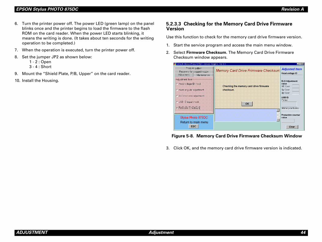
5.2.3.3 Checking for the MVersion
Use this function to check for t
1. Start the service program a
2. Select Firmware Checksum
Checksum window appear
Figure 5-8. Memory Card
3. Click OK, and the memory

C H A P T E R
6INTENANCE
MA
EPSON Stylus PHOTO 875DC Revision A
M 46
6.
SinPHma
AINTENANCE Overview
1 Overview
ce the printer part of the Stylus PHOTO 875DC is common to the Stylus OTO 870, please see the EPSON Stylus PHOTO 870/1270 Service nual.

C H A P T E R
7APPENDIX
EPSON Stylus PHOTO 875DC Revision A
A 48
7.
ThonMa
"
"
"
e connector
7-1. Connectors
Table to refer to
am
tream
t from C364PSB/PSE
nput
ly to the printer
ly to C364MAIN
CN1 Pin Assignment
e Function
Power bus
USB signal line
USB signal line
Ground
CN2 Pin Assignment
e Function
Power bus
USB signal line
USB signal line
Ground
PPENDIX Connector Summary
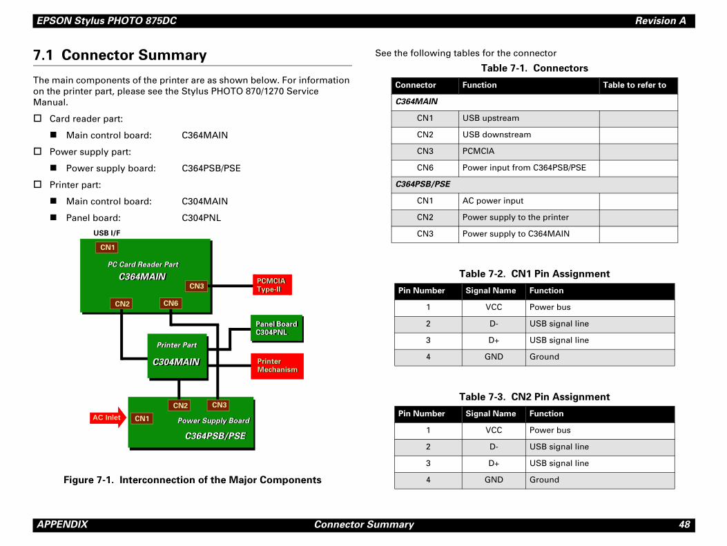
1 Connector Summary
e main components of the printer are as shown below. For information the printer part, please see the Stylus PHOTO 870/1270 Service nual.
Card reader part:
! Main control board: C364MAIN
Power supply part:
! Power supply board: C364PSB/PSE
Printer part:
! Main control board: C304MAIN
! Panel board: C304PNL
Figure 7-1. Interconnection of the Major Components
See the following tables for th
USB I/F
Printer Mechanism
AC Inlet CN1
C364PSB/PSEC364PSB/PSE
PC Card Reader PartPC Card Reader Part
C364MAINC364MAINPCMCIA Type-IIPCMCIA Type-II
CN2
Printer PartPrinter Part
CN2
CN3
CN1
Power Supply BoardPower Supply Board
CN3
CN6
Printer Mechanism
Panel Board C304PNLPanel Board C304PNL
C304MAINC304MAIN
Table
Connector Function
C364MAIN
CN1 USB upstre
CN2 USB downs
CN3 PCMCIA
CN6 Power inpu
C364PSB/PSE
CN1 AC power i
CN2 Power supp
CN3 Power supp
Table 7-2.
Pin Number Signal Nam
1 VCC
2 D-
3 D+
4 GND
Table 7-3.
Pin Number Signal Nam
1 VCC
2 D-
3 D+
4 GND
EPSON Stylus PHOTO 875DC Revision A
A 49
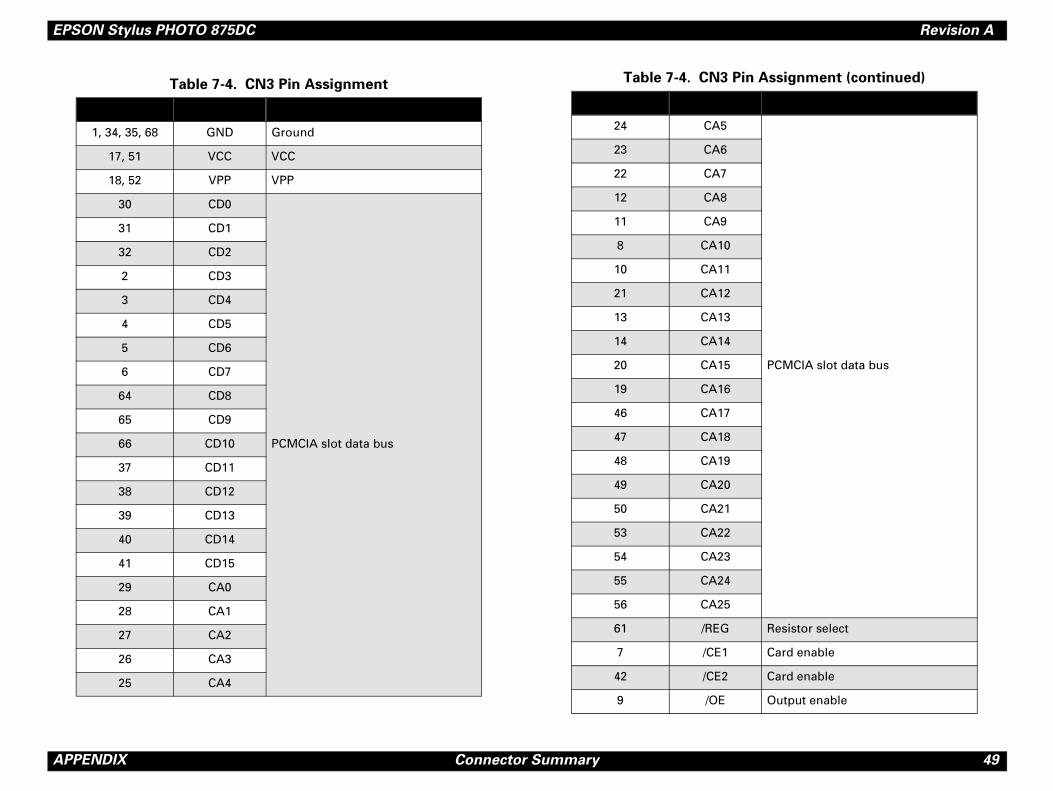
PCMCIA slot data bus
Resistor select
Card enable
Card enable
Output enable
Pin Assignment (continued)
PPENDIX Connector Summary
Table 7-4. CN3 Pin Assignment
1, 34, 35, 68 GND Ground
17, 51 VCC VCC
18, 52 VPP VPP
30 CD0
PCMCIA slot data bus
31 CD1
32 CD2
2 CD3
3 CD4
4 CD5
5 CD6
6 CD7
64 CD8
65 CD9
66 CD10
37 CD11
38 CD12
39 CD13
40 CD14
41 CD15
29 CA0
28 CA1
27 CA2
26 CA3
25 CA4
24 CA5
23 CA6
22 CA7
12 CA8
11 CA9
8 CA10
10 CA11
21 CA12
13 CA13
14 CA14
20 CA15
19 CA16
46 CA17
47 CA18
48 CA19
49 CA20
50 CA21
53 CA22
54 CA23
55 CA24
56 CA25
61 /REG
7 /CE1
42 /CE2
9 /OE
Table 7-4. CN3
EPSON Stylus PHOTO 875DC Revision A
A 50
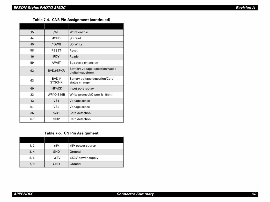
PPENDIX Connector Summary15 /WE Write enable
44 /IORD I/O read
45 /IOWR I/O Write
58 RESET Reset
16 RDY Ready
59 /WAIT Bus cycle extension
62 BVD2/SPKRBatttery voltage detection/Audio digital waveform
63BVD1/
STSCHKBattery voltage detection/Card status change
60 INPACK Input port replay
33 WP/IOIS16B Write protect/I/O port is 16bit
43 VS1 Voltage sense
57 VS2 Voltage sense
36 /CD1 Card detection
67 /CD2 Card detection
Table 7-5. CN Pin Assignment
1, 2 +5V +5V power source
3, 4 GND Ground
5, 6 +3.3V +3.3V power supply
7, 8 GND Ground
Table 7-4. CN3 Pin Assignment (continued)
EPSON Stylus PHOTO 875DC Revision A
A 51
7.
C3
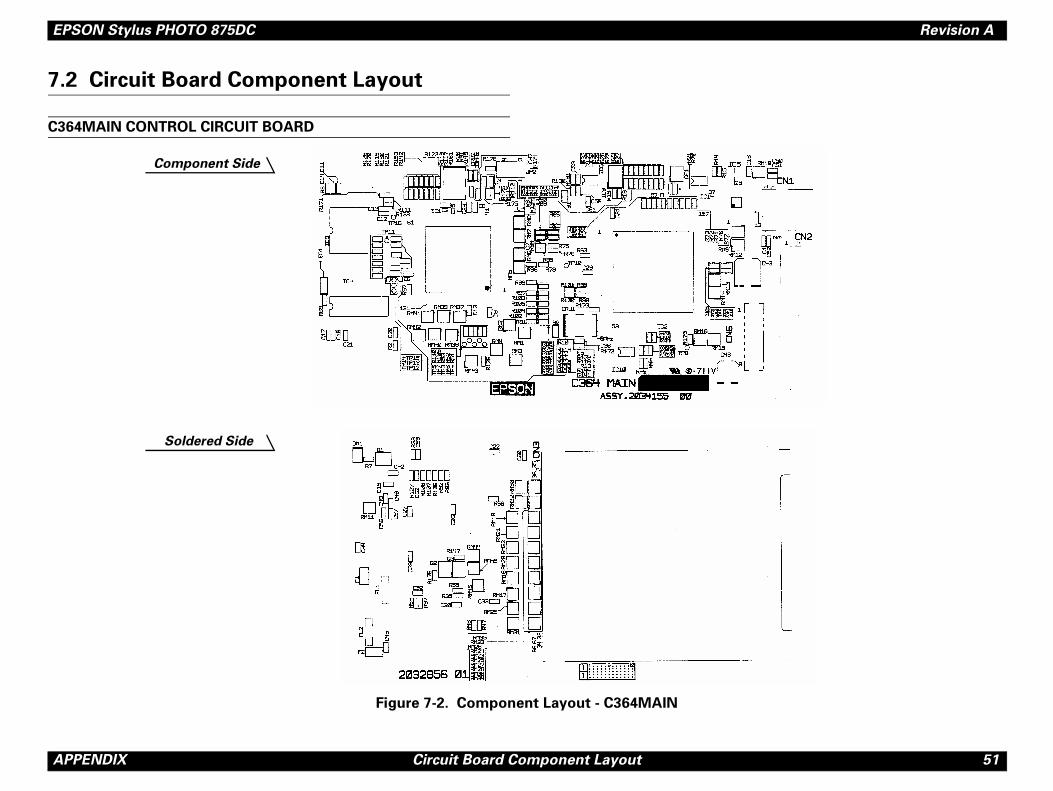
PPENDIX Circuit Board Component Layout
2 Circuit Board Component Layout
64MAIN CONTROL CIRCUIT BOARD
Figure 7-2. Component Layout - C364MAIN
Component Side
Soldered Side
EPSON Stylus PHOTO 875DC Revision A
A 52
C3
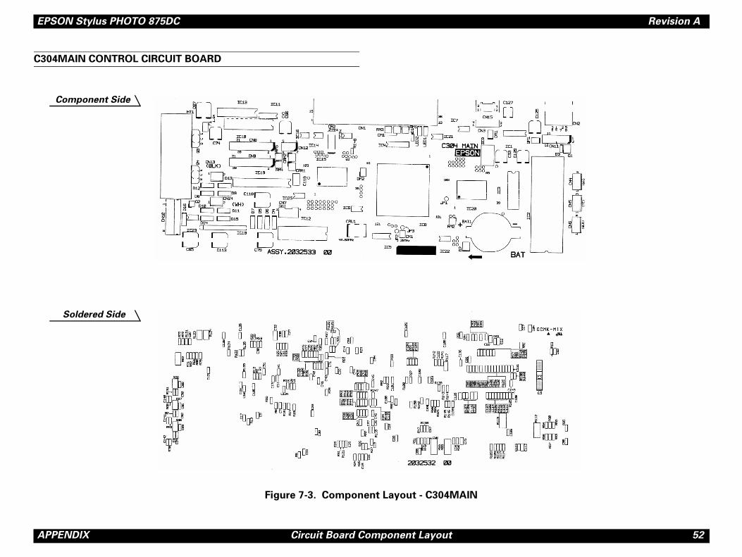
PPENDIX Circuit Board Component Layout
04MAIN CONTROL CIRCUIT BOARD
Figure 7-3. Component Layout - C304MAIN
Component Side
Soldered Side
EPSON Stylus PHOTO 875DC Revision A
A 53
C3
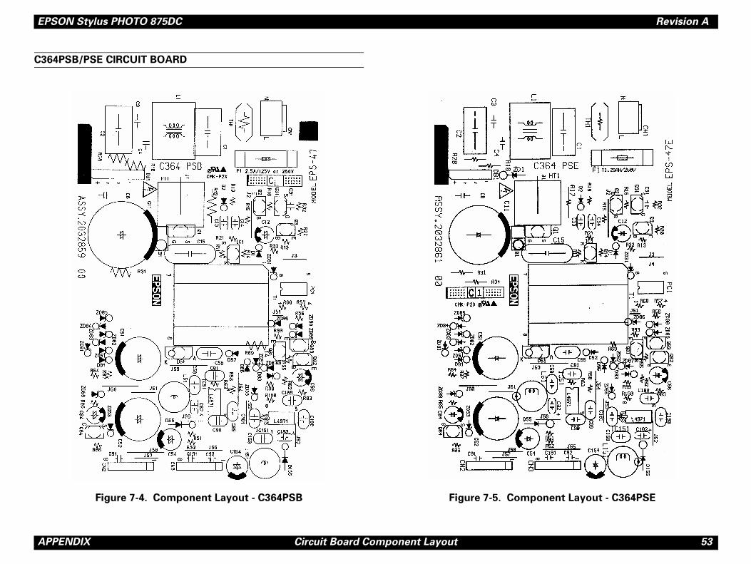
ponent Layout - C364PSE
PPENDIX Circuit Board Component Layout
64PSB/PSE CIRCUIT BOARD
Figure 7-4. Component Layout - C364PSB Figure 7-5. Com
EPSON Stylus PHOTO 875DC Revision A
A 54
C3
PPENDIX Circuit Board Component Layout
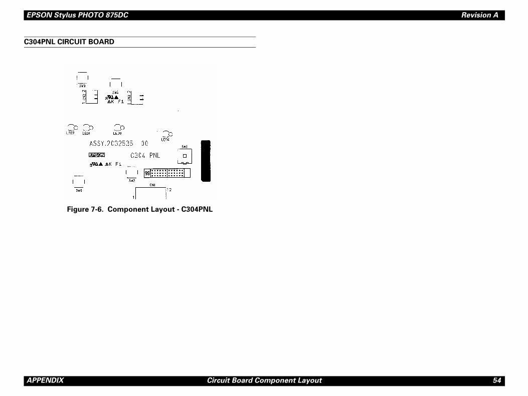
04PNL CIRCUIT BOARD
Figure 7-6. Component Layout - C304PNL
EPSON Stylus PHOTO 875DC Revision A
A 55
7.
. 01 10162 A
115
185
122
122
122
124
0
186125
125
105
125
450
124
101
138
137
139
125
110
126
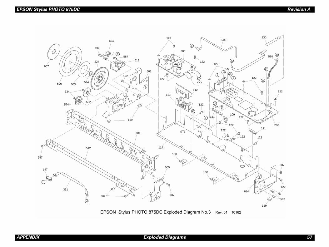
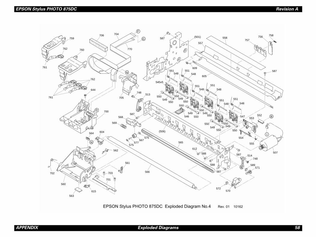
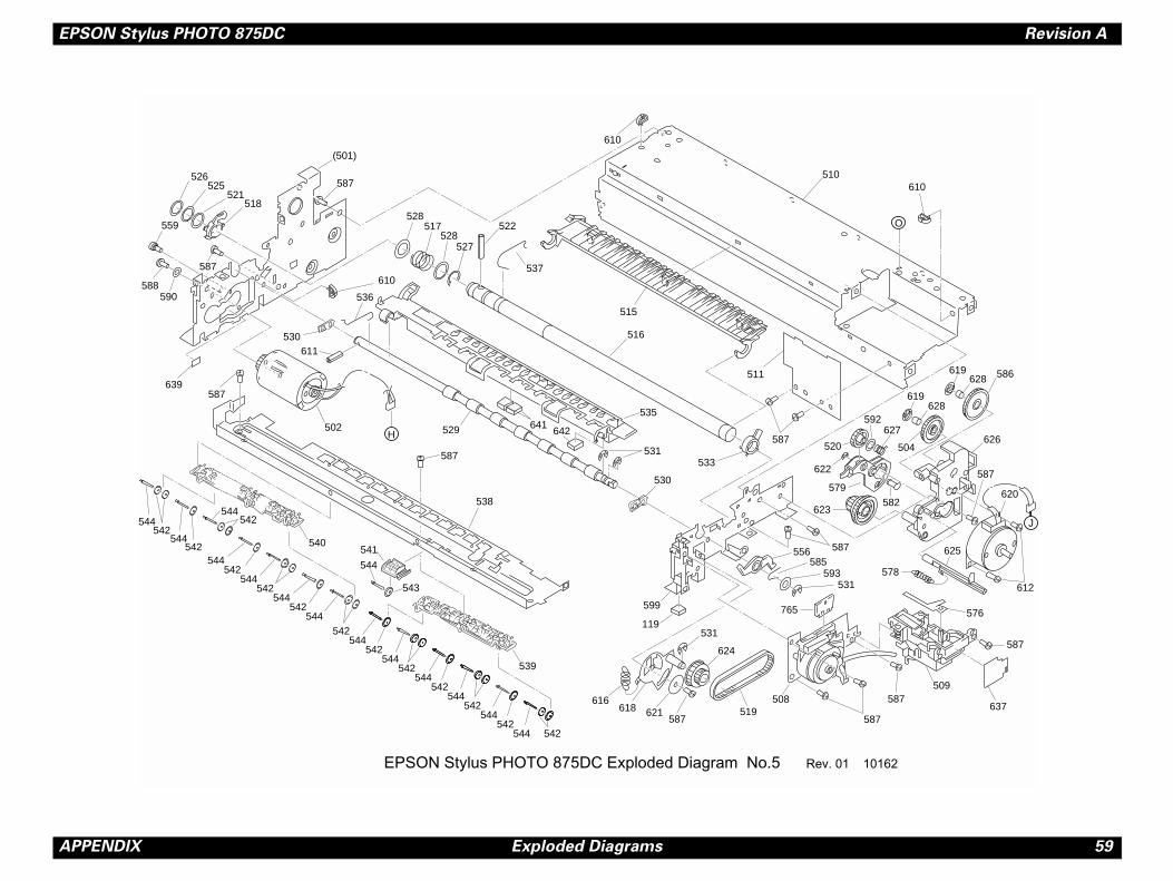
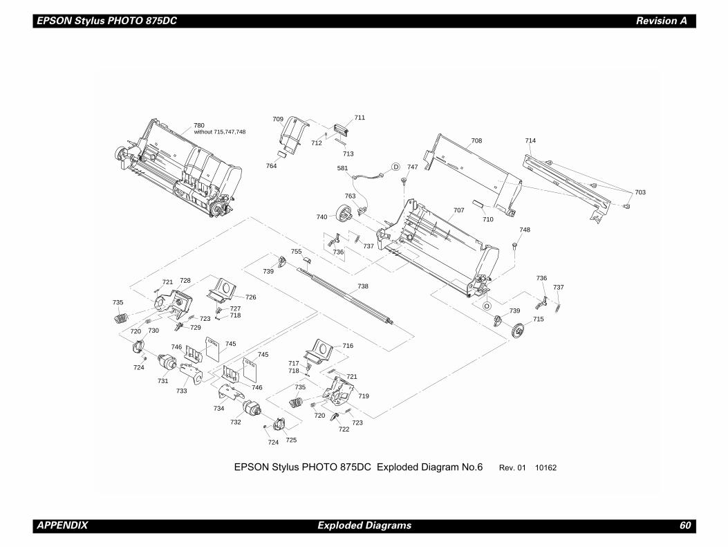
PPENDIX Exploded Diagrams
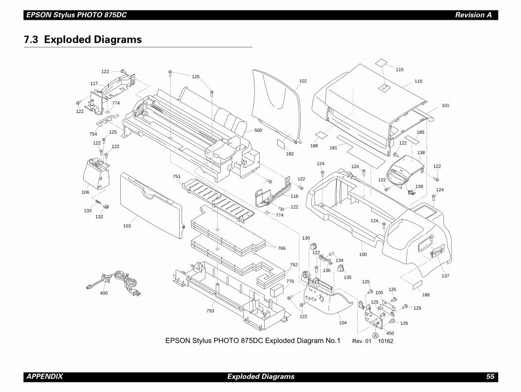
3 Exploded Diagrams
EPSON Stylus PHOTO 875DC Exploded Diagram No.1 Rev
181
124124
122
116
122
102
10
104
130
136
134
135
122
752
766122
400
753
103
774133
132
106
751
500
125122
117
122
774
754 125
122122
182
188
775
EPSON Stylus PHOTO 875DC Revision A
A 56
122
22
M Q
148
144
144
144
122
122 149
v. 01 10162
PPENDIX Exploded Diagrams
122
122
1
P
P
Q
C
332
141
146
145
144
122250
140
143 122
122
142122
122
336
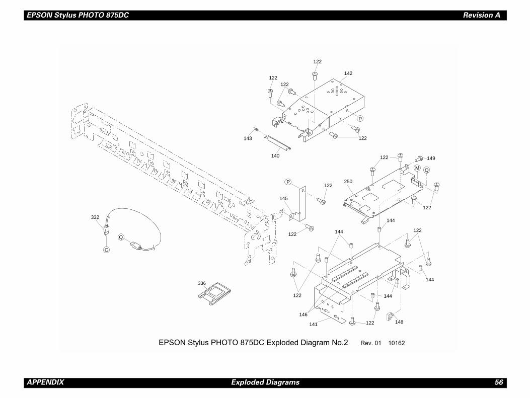
EPSON Stylus PHOTO 875DC Exploded Diagram No.2 Re
EPSON Stylus PHOTO 875DC Revision A
A 57
B
A
D
GF
C
614
119
587
587
122
122122
122
200111
122109
122
580
122
330
10162
PPENDIX Exploded Diagrams
HI
E
E
J
607
K606
M
L
K
L
603594
524
591
604
587613
534
574532
122
501
119
506
113
122
587
512
587 587
505
114
108
108
122
131
122
122
112
122
608
122
300
122
147
331
EPSON Stylus PHOTO 875DC Exploded Diagram No.3 Rev. 01
EPSON Stylus PHOTO 875DC Revision A
A 58
I
B
570
571589
748
507514
552553
757756 758
550549
550
8
51548
551
548
547
555
554
558
587
7
587
ev. 01 10162
PPENDIX Exploded Diagrams
F
N
G
748513
587568
575567
577575
546
(506)
705
706
569
566
588
588
565
572
551
549
(501)587
605
609
548
550
550 550
550549
550
549550
550
550549
550549
550
551548
551548
551
54
5
545x5
557
N
612
58
704
770
759
762
761
760
761
762
644
700
564 604
562
561
703
701
615
563
560
702
EPSON Stylus PHOTO 875DC Exploded Diagram No.4 R
EPSON Stylus PHOTO 875DC Revision A
A 59
O
J
587
531
576
509
626
612
620
23
22
579
582
520
619
627592
619
504
586
610510
637
587
587
587
587
625
578
628
628
59385
ev. 01 10162
PPENDIX Exploded Diagrams
H
526
521525
518
587
(501)
528517
528527
610
536
587
559
588590
530611
529
587
587
538
540541
544
543
544542
544542
544542
539
531
530
119
599
616
624
621587
618 519
556
508
533
516
6
6
535
515
522
537
502
544542
544542
544542
544542
544542
544542
544542
544542
544542
544 542
531
639
641642
765
5
610
511
587
EPSON Stylus PHOTO 875DC Exploded Diagram No.5 R
EPSON Stylus PHOTO 875DC Revision A
A 60
703
714
736737
739715
748
v. 01 10162
PPENDIX Exploded Diagrams
O
D
738
708
710707
711
713
712
737755
764
709
739
736
740
716
721
719
723720
722
725724
735
735
720
724
730
726
723729
721 728
731
733
745746
734
732
746
745
727
717
718
718
780
581
763
747
without 715,747,748
EPSON Stylus PHOTO 875DC Exploded Diagram No.6 Re
EPSON Stylus PHOTO 875DC Revision A
A 61
7.
Se
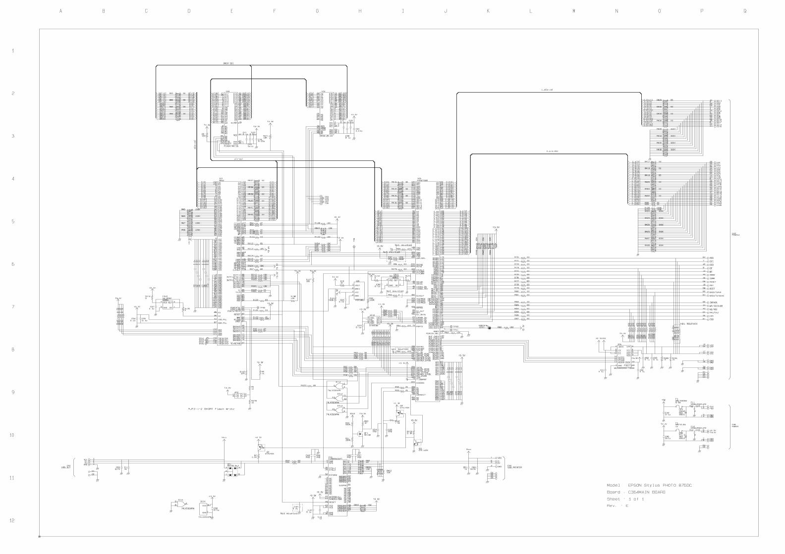
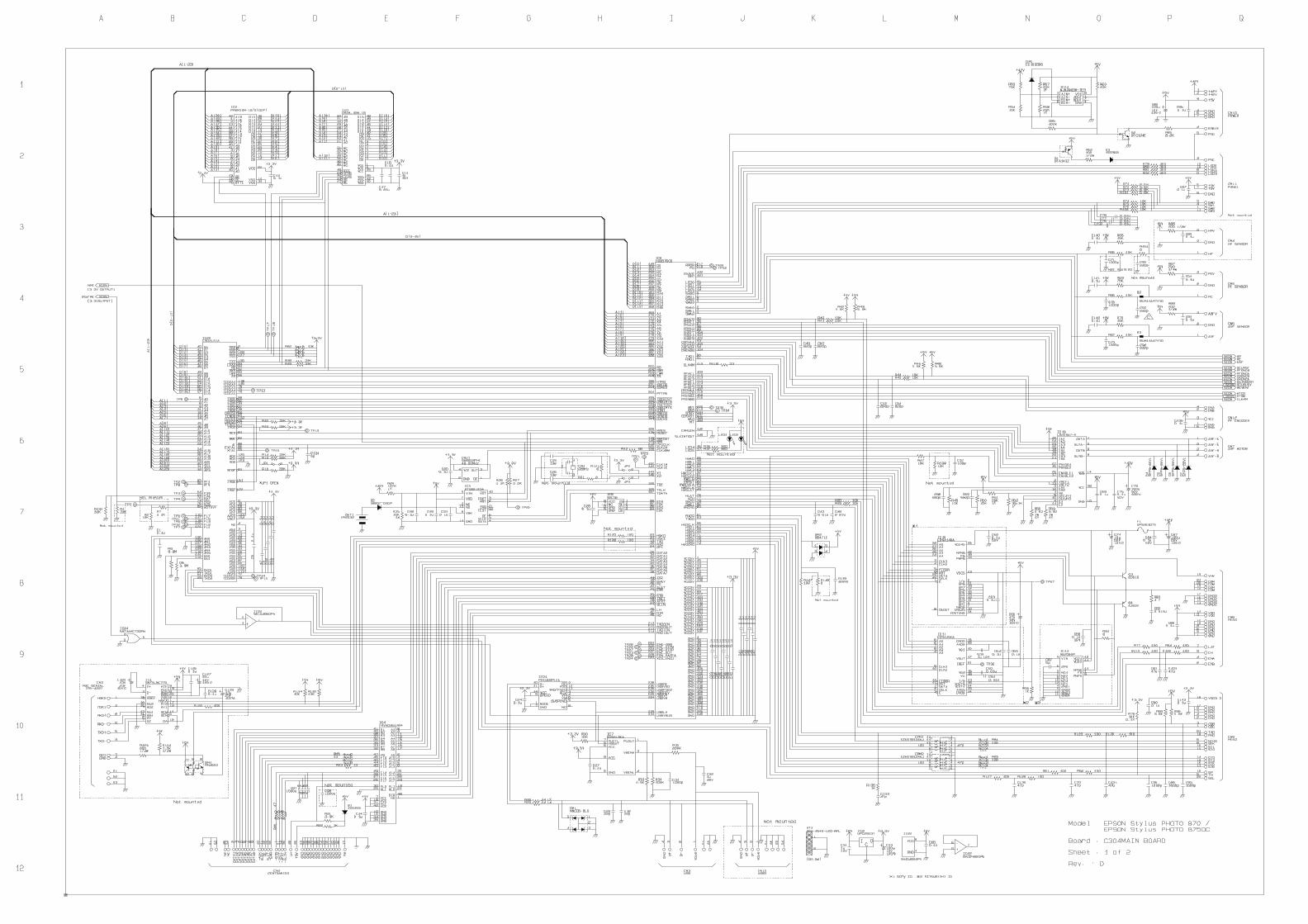
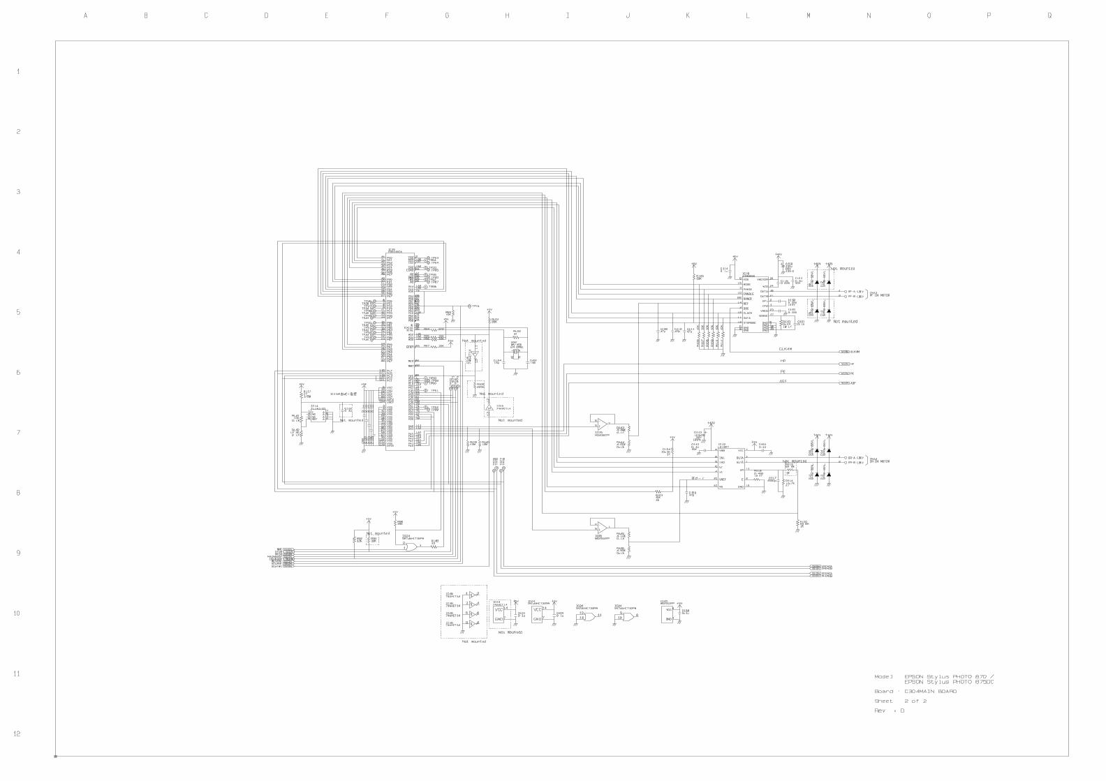
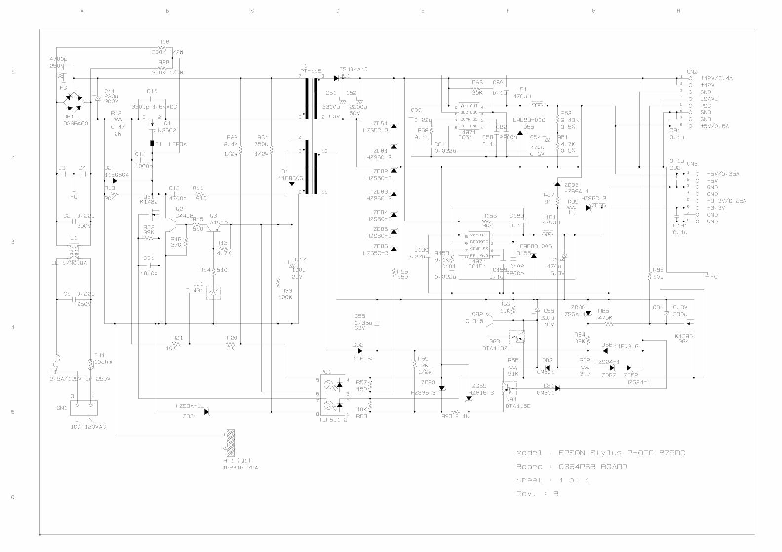
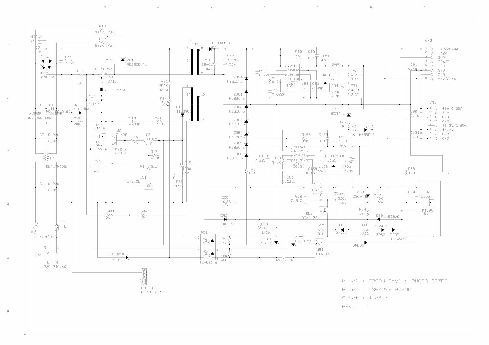
PPENDIX Electrical Circuit Board Diagrams
4 Electrical Circuit Board Diagrams
e the following pages for the electrical circuit board diagrams below:
! C364MAIN
! C304MAIN (1)
! C304MAIN (2)
! C364PSB
! C364PSE