Embed Size (px)
Citation preview

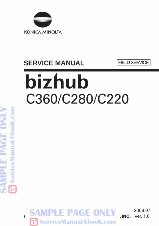
SERVICE MANUAL
2009.07Ver. 1.0
FIELD SERVICE
i
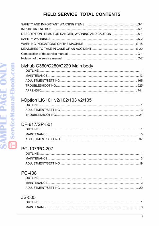
FIELD SERVICE TOTAL CONTENTS
SAFETY AND IMPORTANT WARNING ITEMS ..............................................................S-1IMPORTANT NOTICE .....................................................................................................S-1DESCRIPTION ITEMS FOR DANGER, WARNING AND CAUTION ..............................S-1SAFETY WARNINGS . .....................................................................................................S-2WARNING INDICATIONS ON THE MACHINE .............................................................S-18MEASURES TO TAKE IN CASE OF AN ACCIDENT ....................................................S-20Composition of the service manual ................................................................................. C-1Notation of the service manual ....................................................................................... C-2
bizhub C360/C280/C220 Main bodyOUTLINE ........................................................................................................................ 1MAINTENANCE............................................................................................................ 13ADJUSTMENT/SETTING ........................................................................................... 165TROUBLESHOOTING................................................................................................ 525APPENDIX.................................................................................................................. 741
i-Option LK-101 v2/102/103 v2/105OUTLINE ........................................................................................................................ 1ADJUSTMENT/SETTING ............................................................................................... 3TROUBLESHOOTING.................................................................................................. 21
DF-617/SP-501OUTLINE ........................................................................................................................ 1MAINTENANCE.............................................................................................................. 5ADJUSTMENT/SETTING ............................................................................................. 37
PC-107/PC-207OUTLINE ........................................................................................................................ 1MAINTENANCE.............................................................................................................. 3ADJUSTMENT/SETTING ............................................................................................. 19
PC-408OUTLINE ........................................................................................................................ 1MAINTENANCE.............................................................................................................. 3ADJUSTMENT/SETTING ............................................................................................. 29
JS-505OUTLINE ........................................................................................................................ 1MAINTENANCE.............................................................................................................. 3
ii
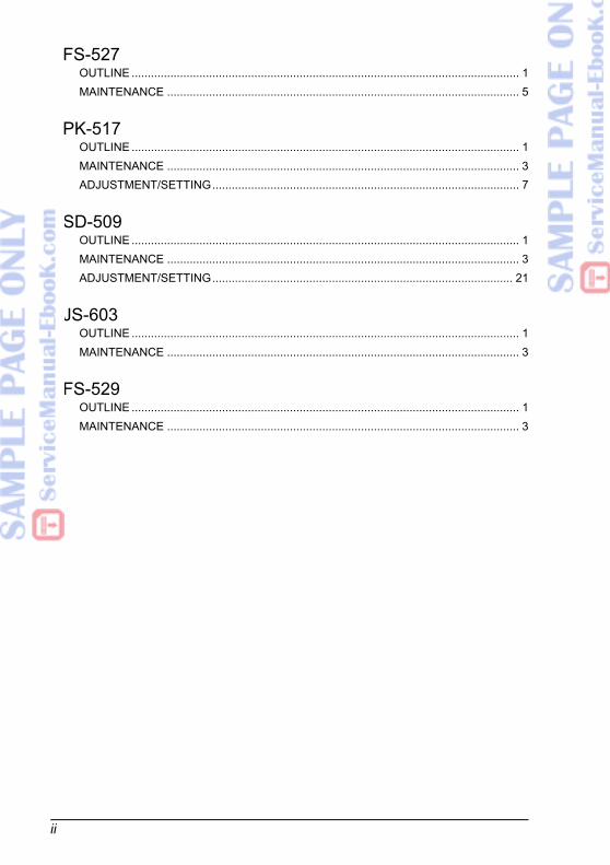
FS-527OUTLINE ........................................................................................................................ 1MAINTENANCE ............................................................................................................. 5
PK-517OUTLINE ........................................................................................................................ 1MAINTENANCE ............................................................................................................. 3ADJUSTMENT/SETTING............................................................................................... 7
SD-509OUTLINE ........................................................................................................................ 1MAINTENANCE ............................................................................................................. 3ADJUSTMENT/SETTING............................................................................................. 21
JS-603OUTLINE ........................................................................................................................ 1MAINTENANCE ............................................................................................................. 3
FS-529OUTLINE ........................................................................................................................ 1MAINTENANCE ............................................................................................................. 3
SERVICE MANUAL
2009.07Ver. 1.0
FIELD SERVICE
M
AIN
TEN
AN
CE
ADJU
STM
ENT
/ SET
TIN
GTR
OU
BLE
SH
OO
TIN
GA
PP
EN
DIX
Field Service Ver. 1.0 Jul. 2009
i
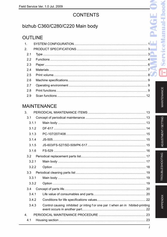
CONTENTS
bizhub C360/C280/C220 Main body
OUTLINE1. SYSTEM CONFIGURATION................................................................................... 12. PRODUCT SPECIFICATIONS................................................................................ 3
2.1 Type ...................................................................................................................... 32.2 Functions .............................................................................................................. 42.3 Paper .................................................................................................................... 62.4 Materials ............................................................................................................... 72.5 Print volume.......................................................................................................... 82.6 Machine specifications.......................................................................................... 92.7 Operating environment ......................................................................................... 92.8 Print functions....................................................................................................... 92.9 Scan functions .................................................................................................... 12
MAINTENANCE3. PERIODICAL MIANTENANCE ITEMS ................................................................. 13
3.1 Concept of periodical maintenance .................................................................... 133.1.1 Main body ................................................................................................... 13
3.1.2 DF-617 ........................................................................................................ 14
3.1.3 PC-107/207/408.......................................................................................... 15
3.1.4 JS-505......................................................................................................... 15
3.1.5 JS-603/FS-527/SD-509/PK-517.................................................................. 15
3.1.6 FS-529 ........................................................................................................ 16
3.2 Periodical replacement parts list......................................................................... 173.2.1 Main body ................................................................................................... 17
3.2.2 Option ......................................................................................................... 18
3.3 Periodical cleaning parts list ............................................................................... 193.3.1 Main body ................................................................................................... 19
3.3.2 Option ......................................................................................................... 19
3.4 Concept of parts life............................................................................................ 203.4.1 Life value of consumables and parts........................................................... 20
3.4.2 Conditions for life specifications values....................................................... 22
3.4.3 Control causing inhibited pr inting f or one par t when an in hibited-printingevent occurs in another part........................................................................ 22
4. PERIODICAL MAINTENANCE PROCEDURE ..................................................... 234.1 Housing section .................................................................................................. 23
C
220
ADJU
STM
ENT
/ SET
TIN
GTR
OU
BLE
SH
OO
TIN
GA
PP
EN
DIX
Field Service Ver. 1.0 Jul. 2009
ii
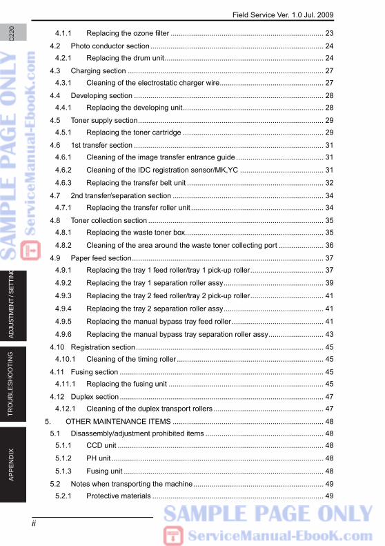
4.1.1 Replacing the ozone filter ........................................................................... 23
4.2 Photo conductor section..................................................................................... 244.2.1 Replacing the drum unit.............................................................................. 24
4.3 Charging section ................................................................................................ 274.3.1 Cleaning of the electrostatic charger wire................................................... 27
4.4 Developing section ............................................................................................. 284.4.1 Replacing the developing unit..................................................................... 28
4.5 Toner supply section........................................................................................... 294.5.1 Replacing the toner cartridge ..................................................................... 29
4.6 1st transfer section ............................................................................................. 314.6.1 Cleaning of the image transfer entrance guide ........................................... 31
4.6.2 Cleaning of the IDC registration sensor/MK,YC ......................................... 31
4.6.3 Replacing the transfer belt unit ................................................................... 32
4.7 2nd transfer/separation section .......................................................................... 344.7.1 Replacing the transfer roller unit ................................................................. 34
4.8 Toner collection section ...................................................................................... 354.8.1 Replacing the waste toner box.................................................................... 35
4.8.2 Cleaning of the area around the waste toner collecting port ...................... 36
4.9 Paper feed section.............................................................................................. 374.9.1 Replacing the tray 1 feed roller/tray 1 pick-up roller.................................... 37
4.9.2 Replacing the tray 1 separation roller assy................................................. 39
4.9.3 Replacing the tray 2 feed roller/tray 2 pick-up roller.................................... 41
4.9.4 Replacing the tray 2 separation roller assy................................................. 41
4.9.5 Replacing the manual bypass tray feed roller ............................................. 41
4.9.6 Replacing the manual bypass tray separation roller assy........................... 43
4.10 Registration section............................................................................................ 454.10.1 Cleaning of the timing roller ........................................................................ 45
4.11 Fusing section .................................................................................................... 454.11.1 Replacing the fusing unit ............................................................................ 45
4.12 Duplex section .................................................................................................... 474.12.1 Cleaning of the duplex transport rollers ...................................................... 47
5. OTHER MAINTENANCE ITEMS .......................................................................... 485.1 Disassembly/adjustment prohibited items .......................................................... 48
5.1.1 CCD unit ..................................................................................................... 48
5.1.2 PH unit ........................................................................................................ 48
5.1.3 Fusing unit .................................................................................................. 48
5.2 Notes when transporting the machine................................................................ 495.2.1 Protective materials .................................................................................... 49
M
AIN
TEN
AAD
JUST
MEN
T / S
ETTI
NG
TRO
UB
LES
HO
OTI
NG
AP
PE
ND
IX
Field Service Ver. 1.0 Jul. 2009
iii
5.3 Disassembly/reassembly parts list...................................................................... 505.4 Cleaning parts list ............................................................................................... 525.5 Disassembly/reassembly procedure................................................................... 53
5.5.1 Front door.................................................................................................... 53
5.5.2 Left cover .................................................................................................... 53
5.5.3 Exit tray ....................................................................................................... 54
5.5.4 Rear right cover........................................................................................... 54
5.5.5 Upper right cover......................................................................................... 54
5.5.6 Upper rear cover ......................................................................................... 55
5.5.7 Lower rear cover/1 ...................................................................................... 55
5.5.8 Lower rear cover/2 ...................................................................................... 55
5.5.9 Scanner rear cover...................................................................................... 56
5.5.10 Scanner right cover ..................................................................................... 56
5.5.11 Scanner right front cover............................................................................. 57
5.5.12 USB interface cover .................................................................................... 57
5.5.13 Scanner left front cover ............................................................................... 57
5.5.14 Scanner upper front cover........................................................................... 58
5.5.15 Scanner left cover ....................................................................................... 58
5.5.16 Scanner upper rear cover ........................................................................... 58
5.5.17 Scanner front cover..................................................................................... 59
5.5.18 Slit glass cover ............................................................................................ 60
5.5.19 Original glass .............................................................................................. 60
5.5.20 Control panel assy ...................................................................................... 61
5.5.21 Tray 1 .......................................................................................................... 61
5.5.22 Tray 2 .......................................................................................................... 62
5.5.23 Front side relay board cover........................................................................ 63
5.5.24 Front cover .................................................................................................. 63
5.5.25 Tray 1 paper feed unit.................................................................................. 64
5.5.26 Tray 2 paper feed unit.................................................................................. 65
5.5.27 PH unit ........................................................................................................ 67
5.5.28 CCD board unit ........................................................................................... 70
5.5.29 Exposure unit .............................................................................................. 71
5.5.30 Sub hopper assy ......................................................................................... 73
5.5.31 Right door assy ........................................................................................... 74
5.5.32 Manual bypass tray unit .............................................................................. 76
5.5.33 Regist unit ................................................................................................... 79
5.5.34 Conveyance unit.......................................................................................... 80
5.5.35 Hard disk drive (HDD) ................................................................................. 81
bizh
ub C
360/
C28
0/C
220
OU
TLIN
EM
AIN
TEN
AN
CE
ADJU
STM
ENT
/ SET
TIN
GTR
OU
BLE
SH
OO
TIN
GA
PP
EN
DIX
Field Service Ver. 1.0 Jul. 2009
5.5.36 How to open PWB box................................................................................ 82
5.5.37 Main drive unit ............................................................................................ 84
5.5.38 Fusing drive unit ......................................................................................... 88
5.5.39 Hopper drive unit (C/K, Y/M)....................................................................... 90
5.5.40 Scanner relay board (REYB/SCAN) ........................................................... 91
5.5.41 Inverter board (INVB).................................................................................. 91
5.5.42 Machine condition monitor board (MCMB) ................................................. 93
5.5.43 Front side relay board (FREYB).................................................................. 93
5.5.44 DC power supply (DCPU)........................................................................... 94
5.5.45 PH relay board (PHREYB).......................................................................... 95
5.5.46 Printer control board (PRCB)...................................................................... 96
5.5.47 Service EEPROM board (SVERB) ............................................................. 97
5.5.48 MFP board (MFPB)..................................................................................... 99
5.5.49 High voltage unit (HV)............................................................................... 102
5.5.50 SODIMM (DIMM) ...................................................................................... 103
5.5.51 NVRAM board (NRB)................................................................................ 104
5.5.52 Paper feed tray 1 paper FD sensor board (PSDB/1) ................................ 104
5.5.53 Paper feed tray 2 paper FD sensor board (PSDB/2) ................................ 105
5.5.54 Paper feed tray 1 LED board, Paper feed tray 2 LED board (LEDB1, LEDB2).................................................................................................................. 106
5.5.55 Scanner motor (M201).............................................................................. 107
5.5.56 Duplex transport motor (M5)..................................................................... 110
5.5.57 Toner supply motor/YM, CK (M8, M9) ...................................................... 112
5.5.58 Transport motor (M1) ................................................................................ 113
5.5.59 Color PC motor (M2)................................................................................. 114
5.5.60 Fusing motor (M3) .................................................................................... 114
5.5.61 Switchback motor (M4) ............................................................................. 115
5.5.62 Fusing pressure roller retraction motor (M11) .......................................... 115
5.5.63 Toner cartridge motor/YM (M6)................................................................. 116
5.5.64 Toner cartridge motor/CK (M7) ................................................................. 116
5.5.65 Color dev. unit engaged motor (M10) ....................................................... 118
5.5.66 Paper feed tray 1 lift-up motor (M12) ........................................................ 119
5.5.67 Paper feed tray 2 lift-up motor (M13) ........................................................ 121
5.5.68 Transfer belt cleaner cooling fan motor (FM6) .......................................... 121
5.5.69 Paper feed tray 1 paper feed clutch (CL3) ................................................ 123
5.5.70 Paper feed tray 2 vertical transport clutch (CL2) ...................................... 124
5.5.71 Paper feed tray 2 paper feed clutch (CL1) ................................................ 124
5 5 72 Manual paper feed clutch (CL7) ................................... 125
bizh
ub C
360/
C28
0/C
220
OU
TLIN
EM
AIN
TEN
AN
CE
ADJU
STM
ENT
/ SET
TIN
GTR
OU
BLE
SH
OO
TIN
GA
PP
EN
DIX
Field Service Ver. 1.0 Jul. 200
v
5.5.73 Developing c
5.5.74 Registration roller clutch (CL4).................................................................. 127
5.5.75 IDC registration sensor shutter solenoid (SD2)......................................... 128
5.5.76 IDC registration sensor/MK, YC (IDCS/MK, YC) assy .............................. 129
5.5.77 PH window cleaning pad........................................................................... 130
5.5.78 Scanner drive cable .................................................................................. 131
5.6 Cleaning procedure .......................................................................................... 1375.6.1 Transfer belt unit........................................................................................ 137
5.6.2 PH window ................................................................................................ 137
5.6.3 Tray 1 feed roller, tray 1 pick-up roller, tray 1 separation roller .................. 138
5.6.4 Tray 2 feed roller, tray 2 pick-up roller, tray 2 separation roller .................. 139
5.6.5 Tray 2 transport roller ................................................................................ 140
5.6.6 Manual bypass tray feed roller .................................................................. 140
5.6.7 Manual bypass tray separation roller ........................................................ 141
5.6.8 Original glass ............................................................................................ 141
5.6.9 Scanner rails ............................................................................................. 142
5.6.10 Mirrors (1st/2nd/3rd) ................................................................................. 143
5.6.11 Lens .......................................................................................................... 143
5.6.12 CCD sensor .............................................................................................. 144
6. SERVICE TOOL.................................................................................................. 1456.1 Service material list .......................................................................................... 1456.2 CE tool list......................................................................................................... 145
7. FIRMWARE REWRITING ................................................................................... 1467.1 Outline .............................................................................................................. 1467.2 USB memory .................................................................................................... 146
7.2.1 Preparation ............................................................................................... 146
7.2.2 Procedure ................................................................................................. 146
7.2.3 Action when data transfer fails .................................................................. 149
7.3 Updating the firmware with the Internet ISW.................................................... 1507.3.1 Outline....................................................................................................... 150
7.3.2 Service environment ................................................................................. 150
7.3.3 Preparations for firmware rewriting ........................................................... 150
7.3.4 Firmware rewriting from the control panel................................................. 153
7.3.5 Firmware rewriting from the CS Remote Care.......................................... 155
7.3.6 Error code list for the Internet ISW............................................................ 156
8. COMMERCIALLY AVAILABLE PARTS................................................................ 1598.1 Installing the key counter .................................................................................. 159
8.1.1 Configuration............................................................................................. 159
bizh
ub C
360/
C28
0/C
220
OU
TLIN
EM
AIN
TEN
AN
CE
ADJU
STM
ENT
/ SET
TIN
GTR
OU
BLE
SH
OO
TIN
GA
PP
EN
DIX
Field Service Ver. 1.0 Jul. 2009
8.1.2 Procedure ................................................................................................. 159
8.2 Installing the original size detection 2 sensor (PS205)..................................... 1628.2.1 Procedure ................................................................................................. 162
ADJUSTMENT/SETTING9. HOW TO USE THE ADJUSTMENT/SETTING SECTION .................................. 16510. UTILITY............................................................................................................... 166
10.1 List of utility mode............................................................................................. 16610.2 Starting/Exiting ................................................................................................. 179
10.2.1 Starting procedure .................................................................................... 179
10.2.2 Exiting procedure...................................................................................... 179
10.3 Touch Panel Adjustment................................................................................... 18010.4 One-Touch User Box Registration .................................................................... 181
10.4.1 Create One-Touch destination-Address Book (Public)/(Personal) ............ 181
10.4.2 Create One-Touch destination-Group....................................................... 182
10.4.3 Create One-Touch destination-E-mail Settings......................................... 183
10.4.4 Create User Box ....................................................................................... 183
10.4.5 Create User Box-Public/Personal User Box.............................................. 183
10.4.6 Create User Box-Bulletin Board User Box ................................................ 184
10.4.7 Create User Box-Relay User Box ............................................................. 184
10.4.8 Limiting Access to Destinations ................................................................ 185
10.4.9 Limiting Access to Destinations-Apply Levels/Groups to Destinations ..... 185
10.5 User Settings.................................................................................................... 18610.5.1 System Settings-Language Selection....................................................... 186
10.5.2 System Settings-Measurement Unit Settings ........................................... 186
10.5.3 System Settings-Paper Tray Settings........................................................ 186
10.5.4 System Settings-Auto Color Level Adjust. ................................................ 187
10.5.5 System Settings-Power Save Settings...................................................... 187
10.5.6 System Settings-Output Settings.............................................................. 188
10.5.7 System Settings-AE Level Adjustment ..................................................... 189
10.5.8 System Settings-Auto Paper Select for Small Original ............................. 189
10.5.9 System Settings-Blank Page Print Settings.............................................. 189
10.5.10 System Settings-Page Number Print Position .......................................... 190
10.5.11 System Settings-Select Keyboard ............................................................ 190
10.5.12 Custom Display Settings-Copier Settings................................................. 191
10.5.13 Custom Display Settings-Scan/Fax Settings ............................................ 192
10.5.14 Custom Display Settings-User Box Settings............................................. 193
10.5.15 Custom Display Settings-Copy Screen..................................................... 194
M
AIN
TEAD
JUST
MEN
T / S
ETTI
NG
TRO
UB
LES
HO
OTI
NG
AP
PE
ND
IX
Field Service Ver. 1.0 Jul. 2009
vii
10.5.16 Custom Display Settings-Fax Active Screen............................................. 194
10.5.17 Custom Display Settings-Color Selection Settings ................................... 194
10.5.18 Custom Display Settings-Left Panel Display Default................................. 195
10.5.19 Custom Display Settings-Search Option Settings..................................... 195
10.5.20 Copier Settings-Auto Booklet ON when Fold & Staple ............................. 195
10.5.21 Copier Settings-Auto Zoom for Combine/Booklet ..................................... 195
10.5.22 Copier Settings-Auto Sort/Group Selection .............................................. 196
10.5.23 Copier Settings-Default Copy Settings...................................................... 196
10.5.24 Copier Settings-Default Enlarge Display Settings..................................... 197
10.5.25 Copier Settings-When AMS Direction is Incorrect .................................... 197
10.5.26 Copier Settings-Separate Scan Output Method........................................ 197
10.5.27 Copier Settings-Enlargement Rotation ..................................................... 198
10.5.28 Copier Settings-Auto Zoom (Platen) ......................................................... 198
10.5.29 Copier Settings-Auto Zoom (ADF) ............................................................ 198
10.5.30 Copier Settings-Specify Default Tray when APS Off ................................. 198
10.5.31 Copier Settings-Select Tray for Insert Sheet ............................................. 199
10.5.32 Copier Settings-Print Jobs During Copy Operation................................... 199
10.5.33 Copier Settings-Automatic Image Rotation ............................................... 199
10.5.34 Copier Settings-Finishing Program ........................................................... 199
10.5.35 Copier Settings-Card Shot Settings .......................................................... 200
10.5.36 Scan/Fax Settings-JPEG Compression Level ........................................... 200
10.5.37 Scan/Fax Settings-Black Compression Level............................................ 200
10.5.38 Scan/Fax Settings-TWAIN Lock Time....................................................... 201
10.5.39 Scan/Fax Settings-Default Scan/Fax Settings........................................... 201
10.5.40 Scan/Fax Settings-Default Enlarge Display Settings ................................ 202
10.5.41 Scan/Fax Settings-Compact PDF/XPS Compression Level ..................... 202
10.5.42 Scan/Fax Settings-Color TIFF Type .......................................................... 202
10.5.43 Scan/Fax Settings-OCR Operation Setting............................................... 203
10.5.44 Scan/Fax Settings-Graphic Outlining ........................................................ 203
10.5.45 Printer Settings-Basic Settings ................................................................. 203
10.5.46 Printer Settings-Paper Setting................................................................... 205
10.5.47 Printer Settings-PCL Settings ................................................................... 207
10.5.48 Printer Settings-PS Setting ....................................................................... 208
10.5.49 Printer Settings-XPS Settings ................................................................... 209
10.5.50 Printer Settings-Print Reports ................................................................... 210
10.5.51 Printer Settings-TIFF Image Paper Setting ............................................... 210
10.5.52 Change Password ..................................................................................... 211
bizh
ub C
360/
C28
0/C
220
OU
TLIN
EM
AIN
TEN
AN
CE
ADJU
STM
ENT
/ SET
TIN
GTR
OU
BLE
SH
OO
TIN
GA
PP
EN
DIX
Field Service Ver. 1.0 Jul. 2009
viii
10.5.53 Change E-mail Address............................................................................ 211
10.5.54 Change Icon ............................................................................................. 211
10.5.55 Register Authentication Settings............................................................... 212
10.5.56 Registered Application Setting-Default Application Selection................... 212
10.5.57 Cellular Phone/PDA Setting-Link File Error Notification ........................... 212
10.5.58 Cellular Phone/PDA Setting-Proxy Server Use ........................................ 212
10.5.59 Cellular Phone/PDA Setting-Print Settings ............................................... 212
10.6 Administrator Settings ...................................................................................... 21310.6.1 System Settings-Power Save Settings...................................................... 213
10.6.2 System Settings-Output Settings.............................................................. 214
10.6.3 System Settings-Date/Time Settings ........................................................ 215
10.6.4 System Settings-Daylight Saving Time..................................................... 215
10.6.5 System Settings-Weekly Timer Settings................................................... 216
10.6.6 System Settings-Restrict User Access ..................................................... 217
10.6.7 System Settings-Expert Adjustment ......................................................... 219
10.6.8 System Settings-List/Counter ................................................................... 246
10.6.9 System Settings-Reset Settings ............................................................... 247
10.6.10 System Settings-User Box Settings.......................................................... 249
10.6.11 System Settings-Standard Size Setting.................................................... 251
10.6.12 System Settings-Stamp Settings .............................................................. 252
10.6.13 System Settings-Blank Page Print Settings.............................................. 252
10.6.14 System Settings-Application Key Settings ................................................ 252
10.6.15 System Settings-Skip Job Operation Settings .......................................... 253
10.6.16 System Settings-Default Bypass Paper Type Setting ............................... 253
10.6.17 System Settings-Page Number Print Position .......................................... 253
10.6.18 System Settings-Advanced Preview Setting............................................. 253
10.6.19 Administrator/Machine Settings-Administrator Registration...................... 253
10.6.20 Administrator/Machine Settings-Input Machine Address .......................... 254
10.6.21 One-Touch/User Box Registration-Create One-Touch Destination........... 254
10.6.22 One-Touch/User Box Registration-Create User Box................................. 256
10.6.23 One-Touch/User Box Registration-One-Touch/User Box Registration List 257
10.6.24 One-Touch/User Box Registration-Maximum Number of User Boxes ...... 258
10.6.25 User Authentication/Account Track-General Settings ............................... 258
10.6.26 User Authentication/Account Track-User Authentication Setting .............. 261
10.6.27 User Authentication/Account Track-Account Track Setting ....................... 263
10.6.28 User Authentication/Account Track-Print without Authentication .............. 263
10.6.29 User Authentication/Account Track-Print Counter List .............................. 264
bizh
ub C
360/
C28
0/C
220
OU
TLIN
EM
AIN
TEN
AN
CE
ADJU
STM
ENT
/ SET
TIN
GTR
OU
BLE
SH
OO
TIN
GA
PP
EN
DIX
Field Service Ver. 1.0 Jul. 2009
ix
10.6.30 User Authentication/Account Track-External Server Settings ................... 264
10.6.31 User Authentication/Account Track-Limiting Access to Destinations ........ 264
10.6.32 User Authentication/Account Track-Authentication Device Settings.......... 265
10.6.33 User Authentication/Account Track-Auth/Acct Track Common Setting...... 266
10.6.34 User Authentication/Account Track-Scan to Home Settings ..................... 266
10.6.35 User Authentication/Account Track-Scan to Authorized Folder Settings... 267
10.6.36 Network Settings-TCP/IP Settings ............................................................ 267
10.6.37 Network Setting-NetWare Settings ........................................................... 273
10.6.38 Network Settings-http Server Settings ...................................................... 276
10.6.39 Network Settings-FTP Settings................................................................. 278
10.6.40 Network Settings-SMB Setting.................................................................. 279
10.6.41 Network Settings-LDAP Settings .............................................................. 281
10.6.42 Network Settings-E-mail Settings ............................................................. 286
10.6.43 Network Settings-SNMP Setting ............................................................... 293
10.6.44 Network Settings-AppleTalk Settings ........................................................ 297
10.6.45 Network Settings-Bonjour Setting ............................................................. 297
10.6.46 Network Settings-TCP Socket Settings..................................................... 298
10.6.47 Network Settings-Network Fax Setting ..................................................... 299
10.6.48 Network Settings-WebDAV Settings ......................................................... 300
10.6.49 Network Settings-Web Service Settings ................................................... 302
10.6.50 Network Settings-SSDP Settings.............................................................. 305
10.6.51 Network Settings-Detail Settings .............................................................. 305
10.6.52 Network Settings-IEEE802.1X Authentication Settings ............................ 310
10.6.53 Network Settings-Web Browser Setting .................................................... 310
10.6.54 Network Settings-Bluetooth Setting .......................................................... 311
10.6.55 Copier Settings-Auto Zoom (Platen) ......................................................... 311
10.6.56 Copier Settings-Auto Zoom (ADF) ............................................................ 311
10.6.57 Copier Settings-Specify Default Tray when APS OFF............................... 311
10.6.58 Copier Settings-Select Tray for Insert Sheet ............................................. 311
10.6.59 Copier Settings-Print Jobs During Copy Operation................................... 312
10.6.60 Copier Settings-Automatic Image Rotation ............................................... 312
10.6.61 Copier Settings-Card Shot Settings .......................................................... 312
10.6.62 Printer Settings-USB Timeout................................................................... 313
10.6.63 Printer Settings-Network Timeout ............................................................. 313
10.6.64 Printer Settings-Print XPS Errors.............................................................. 313
10.6.65 Printer Settings-PSWC Direct Print........................................................... 313
10.6.66 Fax Settings .............................................................................................. 314
bizh
ub C
360/
C28
0/C
220
OU
TLIN
E
TRO
UB
AP
PE
ND
IX l. 2009
x
10.6.67 ... 314
10.6.68 Fax Settings-Header/Footer Position ........................................................ 314
10.6.69 Fax Settings-Line Parameter Setting ........................................................ 315
10.6.70 Fax Settings-TX/RX Settings .................................................................... 316
10.6.71 Fax Settings-Function Settings ................................................................. 318
10.6.72 Fax Settings-PBX Connection Setting ...................................................... 322
10.6.73 Fax Settings-Report Settings.................................................................... 322
10.6.74 Fax Settings-Job Settings List .................................................................. 325
10.6.75 Fax Settings-Multi Lines Settings.............................................................. 326
10.6.76 Fax Settings-Network Fax Settings........................................................... 327
10.6.77 System Connection-OpenAPI Settings..................................................... 330
10.6.78 System Connection-Call Remote Center.................................................. 332
10.6.79 System Connection-Automatic Prefix/Suffix Setting ................................. 332
10.6.80 System Connection-Printer Information.................................................... 332
10.6.81 System Connection-Cellular Phone/PDA Setting ..................................... 332
10.6.82 Security Settings-Administrator Password................................................ 333
10.6.83 Security Settings-User Box Admin. Setting .............................................. 333
10.6.84 Security Settings-Administrator Security Levels ....................................... 334
10.6.85 Security Settings-Security Details ............................................................ 334
10.6.86 Security Settings-Enhanced Security Mode ............................................. 340
10.6.87 Security Settings-HDD Settings................................................................ 341
10.6.88 Security Settings-Function Management Setting...................................... 345
10.6.89 Security Settings-Stamp Settings ............................................................. 346
10.6.90 Security Settings-Image Log Transfer Settings......................................... 347
10.6.91 Security Settings-Driver Password Encryption Setting ............................. 347
10.6.92 License Settings-Get Request Code ........................................................ 348
10.6.93 License Settings-Install License ............................................................... 348
10.6.94 License Settings-List of Enabled Functions.............................................. 348
10.6.95 OpenAPI Authentication Management-Restriction Code Setting ............. 349
10.7 Banner Printing................................................................................................. 34910.8 My Panel Settings............................................................................................. 35010.9 Device Information............................................................................................ 350
11. ADJUSTMENT ITEM LIST.................................................................................. 35212. SERVICE MODE................................................................................................. 354
12.1 List of service mode ......................................................................................... 35412.2 Starting/Exiting ................................................................................................. 359
12.2.1 Starting procedure .................................................................................... 359
12.3 Date/Time Input mode...................................................................................... 360
bizh
ub C
360/
C28
0/C
220
OU
TLIN
EM
AIN
TEN
AN
CE
ADJU
STM
ENT
/ SET
TIN
GTR
OU
BLE
SH
OO
TIN
GA
PP
EN
DIX
Field Service Ver. 1.0 Jul. 2009
xi
12.4 Machine ............................................................................................................ 36112.4.1 Fusing Temperature .................................................................................. 361
12.4.2 Fusing Transport Speed............................................................................ 362
12.4.3 Org. Size Detecting Sensor Adj. ............................................................... 362
12.4.4 Printer Area-Leading Edge Adjustment .................................................... 363
12.4.5 Printer Area-Centering .............................................................................. 364
12.4.6 Printer Area-Leading Edge Adj. (Duplex Side 2)....................................... 365
12.4.7 Printer Area-Centering (Duplex 2nd Side) ................................................ 366
12.4.8 Printer Area-Paper Feed Direction Adj...................................................... 367
12.4.9 Tray Printing Position: Tip.......................................................................... 368
12.4.10 Scan Area ................................................................................................. 369
12.4.11 Scan Area-Image Position: Leading Edge ................................................ 370
12.4.12 Scan Area-Image Position: Side Edge...................................................... 371
12.4.13 Scan Area-Cross Direction Adjustment .................................................... 372
12.4.14 Scan Area-Feed Direction Adjustment...................................................... 373
12.4.15 Printer Resist Loop ................................................................................... 374
12.4.16 Color Registration Adjustment-Cyan, Magenta, Yellow............................. 375
12.4.17 Exhaust fan Stop Delay............................................................................. 376
12.4.18 Skew adjustment-Skew adjustment .......................................................... 376
12.4.19 Skew adjustment-Skew adjustment reset ................................................. 377
12.4.20 Manual Bypass Tray Adjustment ............................................................... 378
12.4.21 Lead Edge Erase Adjustment ................................................................... 379
12.4.22 Split Line Prior Detection .......................................................................... 379
12.4.23 Non-Image Area Erase Check .................................................................. 380
12.5 Firmware Version.............................................................................................. 38012.6 Imaging Process Adjustment ............................................................................ 381
12.6.1 Gradation Adjust ....................................................................................... 381
12.6.2 D Max Density........................................................................................... 382
12.6.3 Background Voltage Margin ...................................................................... 383
12.6.4 Transfer Output Fine Adjustment-Primary transfer adj. ............................. 384
12.6.5 Transfer Output Fine Adjustment-Secondary transfer adj. ........................ 385
12.6.6 Stabilizer-Stabilization Only ...................................................................... 385
12.6.7 Stabilizer-Initialize+Image Stabilization..................................................... 386
12.6.8 Thick Paper Density Adjustment ............................................................... 386
12.6.9 Paper separation adjustment .................................................................... 387
12.6.10 TCR Toner Supply..................................................................................... 387
12.6.11 Monochrome Density Adjustment ............................................................. 388
12 6 12 Development AC Voltage Choice ................................ 388
bizh
ub C
360/
C28
0/C
220
TLIN
E
TRO
UB
LES
HO
AP
PE
ND
IXField Service Ver. 1.0 Jul. 2009
xii
12.7 CS Remote Care .............................................................................................. 38912.7.1 Outlines..................................................................................................... 389
12.7.2 Setting up the CS Remote Care ............................................................... 389
12.7.3 Software SW setting for CS Remote Care................................................ 394
12.7.4 Setup confirmation.................................................................................... 403
12.7.5 Calling the maintenance ........................................................................... 403
12.7.6 Calling the center from the administrator.................................................. 404
12.7.7 Checking the transmission log.................................................................. 404
12.7.8 Detail on settings ...................................................................................... 404
12.7.9 List of the CS Remote Care error code .................................................... 413
12.7.10 Troubleshooting for CS Remote Care ....................................................... 420
12.7.11 CS Remote Care Operation under Enhanced Security Mode .................. 420
12.8 System 1 .......................................................................................................... 42112.8.1 Marketing Area ......................................................................................... 421
12.8.2 Tel/Fax Number......................................................................................... 422
12.8.3 Serial Number........................................................................................... 422
12.8.4 No Sleep ................................................................................................... 423
12.8.5 Foolscap Size Setting ............................................................................... 423
12.8.6 Original Size Detection ............................................................................. 423
12.8.7 Install Date................................................................................................ 424
12.8.8 Initialization-Clear All Data........................................................................ 424
12.8.9 Initialization-Clear Individual Data ............................................................ 424
12.8.10 Initialization-System Error Clear ............................................................... 426
12.8.11 Trouble Isolation........................................................................................ 426
12.8.12 Post card transfer table ............................................................................. 427
12.8.13 Change Warm Up time ............................................................................. 427
12.8.14 Machine State LED Setting....................................................................... 429
12.9 System 2 .......................................................................................................... 43012.9.1 HDD.......................................................................................................... 430
12.9.2 Image Controller Setting ........................................................................... 430
12.9.3 Option Board Status ................................................................................. 431
12.9.4 Consumable Life Reminder ...................................................................... 431
12.9.5 Unit Change.............................................................................................. 432
12.9.6 Software Switch Setting............................................................................ 432
12.9.7 Software Switch Setting-Setting items in the software switch setting ....... 432
12.9.8 Scan Caribration ....................................................................................... 433
12.9.9 LCT Paper Size Setting ............................................................................ 433
12 9 10 Line Mag Setting ........................ 433
bizh
ub C
360/
C28
0/C
220
OU
TLIN
EM
AIN
TEN
AN
CE
ADJU
STM
ENT
/ SET
TIN
GTR
OU
BLE
SH
OO
TIN
GA
PP
EN
DIX
Field Service Ver. 1.0 Jul. 2009
xiii
12.9.11 Data Capture............................................................................................. 434
12.9.12 Split Line Detect. Setting-Prior Detection.................................................. 436
12.9.13 Split Line Detect. Setting-Warning Level................................................... 437
12.9.14 Split Line Detect. Setting-Auto Clean Setting............................................ 437
12.9.15 Stamp........................................................................................................ 437
12.9.16 Network Fax Settings ................................................................................ 438
12.9.17 Image Stabilization Setting ....................................................................... 438
12.9.18 User Paper Settings .................................................................................. 439
12.9.19 Coverage Rate Screen.............................................................................. 440
12.9.20 JAM Code Display Setting ........................................................................ 440
12.9.21 BootUp Screen.......................................................................................... 441
12.9.22 Install Data ................................................................................................ 442
12.9.23 Bluetooth Settings..................................................................................... 442
12.10 Counter ............................................................................................................. 44312.10.1 Common procedure .................................................................................. 443
12.10.2 Life ............................................................................................................ 443
12.10.3 Service Call Counter ................................................................................. 445
12.10.4 Section Service Call.................................................................................. 445
12.10.5 Warning..................................................................................................... 445
12.10.6 Maintenance ............................................................................................. 445
12.10.7 Service Total ............................................................................................. 446
12.10.8 Counter of Each Mode .............................................................................. 446
12.10.9 Service Call History (Data) ....................................................................... 447
12.10.10 ADF Paper Pages ..................................................................................... 447
12.10.11 Paper Jam History..................................................................................... 447
12.10.12 Fax Connection Error ................................................................................ 447
12.10.13 Split Line Counter ..................................................................................... 447
12.10.14 Parts Counter (Fixed)................................................................................ 447
12.10.15 Jam ........................................................................................................... 448
12.10.16 Section JAM.............................................................................................. 448
12.11 List Output ........................................................................................................ 44812.11.1 Machine Management List ....................................................................... 448
12.11.2 Adjustment List ......................................................................................... 448
12.11.3 Parameter List........................................................................................... 448
12.11.4 Service Parameter .................................................................................... 448
12.11.5 Protocol Trace ........................................................................................... 448
12.11.6 Fax Setting List ......................................................................................... 448
12 11 7 Fax Analysis List .................. 448
bizh
ub C
360/
C28
0/C
220
OU
TLIN
EN
TEN
AN
CE
A
PP
EN
Field Service Ver. 1.0 Jul. 2009
xiv
12.12 State Confirmation............................................................................................ 44912.12.1 Sensor Check ........................................................................................... 449
12.12.2 Sensor check screens .............................................................................. 450
12.12.3 Sensor check list....................................................................................... 454
12.12.4 Table Number ........................................................................................... 463
12.12.5 Level History1 ........................................................................................... 463
12.12.6 Level History 2 .......................................................................................... 463
12.12.7 Temp. & Humidity...................................................................................... 464
12.12.8 CCD Check............................................................................................... 464
12.12.9 Memory/HDD Adj.-Memory Check ........................................................... 465
12.12.10 Memory/HDD Adj.-Compress / Decompression Check ............................ 465
12.12.11 Memory/HDD Adj.-Memory Bus Check .................................................... 466
12.12.12 Memory/HDD Adj.-DSC Bus Check.......................................................... 466
12.12.13 Memory/HDD Adj.-HDD R/W Check......................................................... 466
12.12.14 Memory/HDD Adj.-HDD Format ............................................................... 467
12.12.15 Memory/HDD State .................................................................................. 467
12.12.16 Color Regist .............................................................................................. 467
12.12.17 Adjustment Data List................................................................................. 468
12.13 Test Mode......................................................................................................... 46812.13.1 Procedure for test pattern output .............................................................. 468
12.13.2 Gradation Pattern ..................................................................................... 468
12.13.3 Halftone Pattern........................................................................................ 469
12.13.4 Lattice Pattern........................................................................................... 470
12.13.5 Solid Pattern ............................................................................................. 471
12.13.6 Color Sample ............................................................................................ 471
12.13.7 8 Color Solid Pattern................................................................................. 472
12.13.8 CMM pattern............................................................................................. 472
12.13.9 Running Mode .......................................................................................... 473
12.13.10 Fax Test .................................................................................................... 473
12.14 ADF .................................................................................................................. 47412.14.1 Original Stop Position ............................................................................... 474
12.14.2 Registration Loop Adj. .............................................................................. 475
12.14.3 Auto Stop Position Adjustment ................................................................. 476
12.14.4 Paper Passage ......................................................................................... 478
12.14.5 Sensor Check ........................................................................................... 479
12.14.6 Original Tray Width.................................................................................... 481
12.14.7 Read Pos Adj ............................................................................................ 482
12.14.8 Feed Zoom ............................................................................................... 484
bizh
ub C
360/
C28
0/C
220
OU
TLIN
EM
AIN
TEN
AN
CE
ADJU
STM
ENT
/ SET
TIN
GTR
OU
BLE
SH
OO
TIN
GA
PP
EN
DIX
Field Service Ver. 1.0 Jul. 2009
xv
12.14.9 Scanning Light Adjustment ....................................................................... 485
12.14.10 Mixed original Size adjustment ................................................................. 485
12.15 FAX................................................................................................................... 48512.16 Finisher ............................................................................................................. 486
12.16.1 FS-FN adjustment - Center Staple Position .............................................. 486
12.16.2 FS-FN adjustment - Half-Fold Position...................................................... 487
12.16.3 FS-FN adjustment - Punch Horizontal Position......................................... 488
12.16.4 FS-FN adjustment - Punch Regist Loop Size ........................................... 489
12.16.5 FS-FN adjustment - finisher check............................................................ 489
12.16.6 FS-FN adjustment - Load Data ................................................................. 491
12.16.7 FS-FN adjustment - Alignment Plate Position........................................... 491
12.16.8 FS-FN adjustment - Side position adjustment .......................................... 491
12.16.9 Punch Option Setting ................................................................................ 492
12.16.10 Job Separator ........................................................................................... 492
12.17 Internet ISW...................................................................................................... 49312.17.1 Internet ISW Set........................................................................................ 493
12.17.2 HTTP Setting ............................................................................................ 493
12.17.3 HTTP Setting-Data Input Setting .............................................................. 493
12.17.4 HTTP Setting-Connect Proxy.................................................................... 493
12.17.5 HTTP Setting-Proxy Server....................................................................... 494
12.17.6 HTTP Setting-Proxy Authentication .......................................................... 494
12.17.7 HTTP Setting-Connection Time-Out ......................................................... 494
12.17.8 FTP Setting ............................................................................................... 494
12.17.9 FTP Setting-Data Input Setting ................................................................. 494
12.17.10 FTP Setting-Connect Proxy ...................................................................... 495
12.17.11 FTP Setting-Proxy Server ......................................................................... 495
12.17.12 FTP Setting-Connection Setting ............................................................... 495
12.17.13 Forwarding Access Setting-User ID .......................................................... 495
12.17.14 Forwarding Access Setting-Password....................................................... 496
12.17.15 Forwarding Access Setting-URL ............................................................... 496
12.17.16 Forwarding Access Setting-FileName....................................................... 496
12.17.17 Download .................................................................................................. 496
13. ENHANCED SECURITY..................................................................................... 49713.1 List of Enhanced Security................................................................................. 49713.2 Starting/Exiting ................................................................................................. 497
13.2.1 Starting procedure .................................................................................... 497
13.2.2 Exiting procedure ...................................................................................... 497
13.3 Enhanced Security ........................................................................................... 498
bizh
O
UTL
INE
MA
INTE
NA
NC
EAD
JUST
MEN
T / S
ETTI
NG
TRO
UB
LES
HO
OTI
NG
AP
PE
ND
IXField Service Ver. 1.0 Jul. 2009
13.3.1 CE Password ............................................................................................ 498
13.3.2 Administrator Password ............................................................................ 498
13.3.3 Administrator Feature Level ...................................................................... 499
13.3.4 CE Authentication ..................................................................................... 499
13.3.5 DC/DevC Lifestop ..................................................................................... 500
13.3.6 NVRAM Data Backup ............................................................................... 500
13.3.7 Operation Ban release time ...................................................................... 500
13.3.8 Administrator unlocking............................................................................. 501
13.3.9 Engine FW DipSW.................................................................................... 501
14. BILLING SETTING.............................................................................................. 50414.1 List of billing setting .......................................................................................... 50414.2 Starting/Exiting ................................................................................................. 504
14.2.1 Starting procedure .................................................................................... 504
14.2.2 Exiting procedure...................................................................................... 504
14.3 Billing Setting.................................................................................................... 50514.3.1 Counter Setting......................................................................................... 505
14.3.2 Management Function Choice.................................................................. 508
14.3.3 Management Function Choice-Key Counter IF Vendor ............................ 508
14.3.4 Management Function Choice-Authentication Device 1 ........................... 508
14.3.5 Management Function Choice-Authentication Device 2 ........................... 509
14.3.6 Management Function Choice-Key Counter Only .................................... 511
14.3.7 Management Function Choice-Management Device 1............................. 512
14.3.8 Management Function Choice-Management Device 2............................. 512
14.3.9 Management Function Choice-Vendor 1 .................................................. 512
14.3.10 Management Function Choice-Vendor 2 .................................................. 513
14.3.11 Coverage Rate Clear ................................................................................ 516
14.3.12 OpenAPI Authentication Management-Restriction Code.......................... 517
14.3.13 OpenAPI Authentication Management-Region Code ............................... 517
15. CONTENTS TO BE CLEARED BY RESET FUNCTION .................................... 51816. MECHANICAL ADJUSTMENT ........................................................................... 519
16.1 Mechanical adjustment of the scanner section ................................................ 51916.1.1 Adjustment of the scanner motor belt ....................................................... 519
16.1.2 Positioning of the exposure unit and mirrors unit ...................................... 520
16.2 Mechanical adjustment of the paper feed section ............................................ 52216.2.1 Skew adjustment of the tray 1/2................................................................ 522
16.2.2 Centering adjustment of the tray 1/2......................................................... 523
16.2.3 Adjustment of the bypass paper size unit ................................................. 524
bizh
ub C
360/
C28
0/C
220
OU
TLIN
EM
AIN
TEN
AN
CE
ADJU
STM
ENT
/ SET
TIN
GTR
OU
BLE
SH
OO
TIN
GA
PP
EN
DIX
F
xvii
17. JAM DISPLAY ..................................................................................................... 52517.1 List of JAM code ............................................................................................... 525
17.1.1 Misfeed display resetting procedure ......................................................... 535
17.2 Sensor layout .................................................................................................... 53617.2.1 Main body ................................................................................................. 536
17.2.2 DF-617 ...................................................................................................... 537
17.2.3 PC-107/PC-207......................................................................................... 538
17.2.4 PC-408...................................................................................................... 539
17.2.5 JS-505....................................................................................................... 540
17.2.6 FS-529 ...................................................................................................... 540
17.2.7 FS-527/SD-509/PK-517/JS-603................................................................ 541
17.3 Solution............................................................................................................. 54217.3.1 Initial check items...................................................................................... 542
17.3.2 Misfeed at manual bypass feed section .................................................... 542
17.3.3 Misfeed at tray 1 feed section ................................................................... 543
17.3.4 Misfeed at tray 2 feed section ................................................................... 543
17.3.5 Tray3 feed section/vertical transport section misfeed................................ 544
17.3.6 Tray4 feed section/vertical transport section misfeed................................ 544
17.3.7 LCT paper feed section/vertical transport section misfeed ....................... 545
17.3.8 Misfeed at vertical transport section ......................................................... 545
17.3.9 Misfeed at 2nd image transfer section ...................................................... 546
17.3.10 Misfeed at exit section............................................................................... 546
17.3.11 ADF turnover section ................................................................................ 547
17.3.12 ADF paper feed section ............................................................................ 547
17.3.13 ADF transport section ............................................................................... 548
17.3.14 ADF paper exit section.............................................................................. 548
17.3.15 ADF image reading section....................................................................... 549
17.3.16 Code: 72-14 .............................................................................................. 549
17.3.17 Code: 72-15 .............................................................................................. 550
17.3.18 Code: 72-16 .............................................................................................. 550
17.3.19 Code: 72-17 .............................................................................................. 551
17.3.20 Code: 72-18 .............................................................................................. 552
17.3.21 Code: 72-19 .............................................................................................. 552
17.3.22 Code: 72-21 .............................................................................................. 552
17.3.23 Code: 72-22 .............................................................................................. 553
17.3.24 Code: 72-26 .............................................................................................. 553
bizh
ub C
360/
C28
0/C
220
OU
TLIN
EM
AIN
TEN
AN
CE
ADJU
STM
ENT
/ SET
TIN
GTR
OU
BLE
SH
OO
TIN
GA
PP
EN
DIX
Field Service Ver. 1.0 Jul. 2009
xvii
17.3.25 Code: 72-43 .............................................................................................. 554
17.3.26 Code: 72-81 .............................................................................................. 554
17.3.27 Code: 72-85 .............................................................................................. 554
17.3.28 Code: 72-86 .............................................................................................. 555
17.3.29 Code: 72-87 .............................................................................................. 555
17.3.30 Misfeed at duplex pre-registration section ................................................ 556
17.3.31 Misfeed at duplex transport section .......................................................... 556
18. MALFUNCTION CODE....................................................................................... 55718.1 Display procedure............................................................................................. 55718.2 List .................................................................................................................... 55818.3 Solution ............................................................................................................ 560
18.3.1 S-1: CCD gain adjustment failure ............................................................. 560
18.3.2 D-1: Split line detect.................................................................................. 560
18.3.3 P-5: IDC sensor (front) failure................................................................... 561
18.3.4 P-28 IDC sensor (rear) failure................................................................... 561
18.3.5 P-6: Drum/Development unit (C) failure.................................................... 562
18.3.6 P-7: Drum/Development unit (M) failure ................................................... 562
18.3.7 P-8: Drum/Development unit (Y) failure .................................................... 562
18.3.8 P-9: Drum/Development unit (K) failure .................................................... 562
18.3.9 P-14: Skew correction trouble................................................................... 563
18.3.10 P-21: Color regist test pattern failure ........................................................ 563
18.3.11 P-22: Color regist adjust failure................................................................. 564
18.3.12 P-27: Secondary transfer ATVC failure ..................................................... 564
18.3.13 P-30: PC home sensor (color) malfunction............................................... 565
18.3.14 P-31: PC home sensor (K) malfunction .................................................... 565
19. TROUBLE CODE................................................................................................ 56619.1 Display procedure............................................................................................. 56619.2 Trouble resetting procedure.............................................................................. 566
19.2.1 Trouble resetting procedure by Trouble Reset key.................................... 566
19.3 Trouble isolation function .................................................................................. 56719.4 List .................................................................................................................... 56719.5 Solution ............................................................................................................ 605
19.5.1 C0001: LCT communication error............................................................. 605
19.5.2 C0202: Tray 1 feeder up/down abnormality .............................................. 605
19.5.3 C0204: Tray 2 feeder up/down abnormality .............................................. 606
19.5.4 C0206: Tray3 lift-up failure ........................................................................ 607
19.5.5 C0208: Tray4 lift-up failure ........................................................................ 607
19.5.6 C0209: LCT elevator motor failure ............................................................ 608
bizh
ub C
360/
C28
0/C
220
OU
TLIN
EA
NC
E
AP
PE
ND
IX
Field Service Ver. 1.0 Jul. 2
xix
19.5.7 C0210: LC
19.5.8 C0211: Manual feed up/down abnormality................................................ 609
19.5.9 C0212: LCT lock release failure................................................................ 609
19.5.10 C0213: LCT shift gate operation failure .................................................... 610
19.5.11 C0214: LCT shift failure ............................................................................ 610
19.5.12 C0215: LCT shift motor failure .................................................................. 611
19.5.13 C1004: FNS communication error............................................................. 611
19.5.14 C1081: SD communication error............................................................... 612
19.5.15 C1113: Center-staple lead edge stopper motor malfunction .................... 612
19.5.16 C1114: Center-staple front adjust drive motor malfunction....................... 613
19.5.17 C1115: Center-staple knife drive motor malfunction ................................. 613
19.5.18 C1116: Center-staple transfer motor malfunction ..................................... 614
19.5.19 C1150: Center-staple rear adjust drive motor malfunction........................ 614
19.5.20 C1156: Center-staple paddle roller motor malfunction (trailing edge)....... 615
19.5.21 C1181: Malfunctioning of belt up/down movement ................................... 616
19.5.22 C1182: Shift motor drive malfunction........................................................ 617
19.5.23 C1183: Elevate drive malfunction ............................................................. 618
19.5.24 C1190: Alignment plate motor dr ive malfunction / Alignment pla te R dr ivemalfunction................................................................................................ 620
19.5.25 C1191: Alignment plate F drive malfunction ............................................. 621
19.5.26 C1194: Leading edge stopper motor drive malfunction ............................ 621
19.5.27 C11A1: Tray 2 exit roller pressure/ retraction malfunction / Exit roller pressure/ retraction malfunction................................................ 622
19.5.28 C11A2: Accommodation roller pressure/ retraction malfunction ............... 623
19.5.29 C11A7: Tray 3 exit roller pressure/ retraction malfunction......................... 624
19.5.30 C11B0: Stapler movement drive malfunction............................................ 624
19.5.31 C11B2: Staple drive malfunction............................................................... 625
19.5.32 C11B5: Saddle stapler drive malfunction.................................................. 626
19.5.33 C11C0: Punch motor drive malfunction .................................................... 626
19.5.34 C11E0: Duplex path switching motor drive malfunction / Finisher route change malfunction............................................................ 627
19.5.35 C11E1: Upper lower path switching motor drive malfunction.................... 628
19.5.36 C11E2: Tray1 path switching motor drive malfunction .............................. 628
19.5.37 C1301: Fan motor drive malfunction ......................................................... 629
19.5.38 C1402: FS NVRAM memory error ............................................................ 629
19.5.39 C2152: Transfer belt pressure welding alienation ..................................... 630
19.5.40 C2164: PC charge malfunction ................................................................. 630
19.5.41 C2253: Color PC drum motor’s failure to turn ........................................... 631
bizh
ub C
360/
C28
0/C
220
OU
TLIN
EM
AIN
TEN
AN
CE
ADJU
STM
ENT
/ SET
TIN
GTR
OU
BLE
SH
OO
TIN
GA
PP
EN
DIX
Field Service Ver. 1.0 Jul. 2009
xx
19.5.42 C2254: Color PC drum motor’s turning at abnormal timing ...................... 631
19.5.43 C225D: Color developing unit de-engagement failure .............................. 631
19.5.44 C2355: Transfer belt cleaner cooling fan motor’s failure to turn................ 632
19.5.45 C2411: Developing unit (C) new article release........................................ 632
19.5.46 C2412: Developing unit (M) new article release ....................................... 632
19.5.47 C2413: Developing unit (Y) new article release........................................ 632
19.5.48 C2414: Developing unit (K) new article release........................................ 632
19.5.49 C2551: Abnormally low toner density detected cyan TCR sensor............ 633
19.5.50 C2553: Abnormally low toner density detected magenta TCR sensor ..... 633
19.5.51 C2555: Abnormally low toner density detected yellow TCR sensor ......... 633
19.5.52 C2557: Abnormally low toner density detected black TCR sensor ........... 633
19.5.53 C2552: Abnormally high toner density detected cyan TCR sensor .......... 634
19.5.54 C2554: Abnormally high toner density detected magenta TCR sensor.... 634
19.5.55 C2556: Abnormally high toner density detected yellow TCR sensor........ 634
19.5.56 C2558: Abnormally high toner density detected black TCR sensor ......... 634
19.5.57 C2559: Cyan TCR sensor adjustment failure ........................................... 635
19.5.58 C255A: Magenta TCR sensor adjustment failure ..................................... 635
19.5.59 C255B: Yellow TCR sensor adjustment failure ......................................... 635
19.5.60 C255C: Black TCR sensor adjustment failure .......................................... 635
19.5.61 C2561: Cyan TCR sensor failure .............................................................. 636
19.5.62 C2562: Magenta TCR sensor failure ........................................................ 636
19.5.63 C2563: Yellow TCR sensor failure ............................................................ 636
19.5.64 C2564: Black TCR sensor failure.............................................................. 636
19.5.65 C2650: Main backup media access error ................................................. 637
19.5.66 C2A11: Drum unit/C new article release .................................................. 638
19.5.67 C2A12: Drum unit/M new article release .................................................. 638
19.5.68 C2A13: Drum unit/Y new article release................................................... 638
19.5.69 C2A14: Drum unit/K new article release................................................... 638
19.5.70 C3101: Fusing roller separation failure ..................................................... 639
19.5.71 C3201: Fusing motor failure to turn .......................................................... 639
19.5.72 C3202: Fusing motor turning at abnormal timing ..................................... 639
19.5.73 C3302: Fusing cooling fan motor/2, 3 failure to turn ................................. 640
19.5.74 C3421: Fusing heaters trouble (Heating side) .......................................... 640
19.5.75 C3423: Fusing heaters trouble (Pressurizing side)................................... 640
19.5.76 C3721: Fusing abnormally high temperature detection (Center of the heating side) ...................................................................... 641
19.5.77 C3722: Fusing abnormally high temperature detection (Edge of the heating side)......................................................................... 641
bizh
ub C
360/
C28
0O
UTL
INE
MA
INTE
NA
NC
EAD
JUST
MEN
T / S
ETTI
NG
TRO
UB
LES
HO
OTI
NG
AP
PE
ND
IX
Field Service Ver. 1.0 Jul. 2009
xxi
19.5.78 C3723: Fusing abnormally high temperature detection (Pressurizing side).................................................................................................................. 641
19.5.79 C3821: Fusing abnormally low temperature detection (Heating side) ...... 641
19.5.80 C3823: Fusing abnormally low temperature detection (Pressurizing side).................................................................................................................. 641
19.5.81 C3921: Fusing sensor wire breaks detection (Heating side) .................... 642
19.5.82 C3923: Fusing sensor wire breaks detection (Pressurizing side) ............. 642
19.5.83 C4101: Polygon motor rotation trouble...................................................... 642
19.5.84 C4501: Laser malfunction ......................................................................... 643
19.5.85 C5102: Transport motor’s failure to turn.................................................... 643
19.5.86 C5103: Transport motor’s turning at abnormal timing ............................... 643
19.5.87 C5351: Power supply cooling fan motor/1’s failure to turn ........................ 644
19.5.88 C5354: Exhaust fan motor’s failure to turn ................................................ 644
19.5.89 C5355: Cooling fan motor/3’s failure to turn.............................................. 645
19.5.90 C5501: AC signal abnormality .................................................................. 645
19.5.91 C5601: Engine control malfunction ........................................................... 645
19.5.92 C6102: Drive system home sensor malfunction........................................ 646
19.5.93 C6103: Slider over running ....................................................................... 646
19.5.94 C6704: Image input time out..................................................................... 647
19.5.95 C6751: CCD clamp/gain adjustment failure .............................................. 647
19.5.96 C6752: ASIC clock input error (front side) ................................................ 648
19.5.97 C6753: ASIC clock input error (back side) ................................................ 648
19.5.98 C6901: DSC board mount failure 1 ........................................................... 648
19.5.99 C6902: DSC board bus check NG1-1 ....................................................... 648
19.5.100 C6903: DSC board bus check NG1-2 ....................................................... 648
19.5.101 C6F01: Scanner sequence trouble 1 ........................................................ 648
19.5.102 C8101: Before reading pressure welding alienation mechanism trouble .. 649
19.5.103 C8102: Turn around pressure welding alienation trouble.......................... 649
19.5.104 C8103: Lift up mechanism trouble (Upward movement) ........................... 650
19.5.105 C8106: Lift up mechanism trouble (Downward movement) ...................... 650
19.5.106 C8107: Glass cleaning mechanism trouble............................................... 651
19.5.107 C8302: Cooling fan trouble ....................................................................... 651
19.5.108 C8401: EEPROM failure ........................................................................... 652
19.5.109 C9401: Exposure turning on the lamp trouble detection........................... 652
19.5.110 C9402: Exposure turning on the lamp abnormally detection .................... 652
19.5.111 CA051: Standard controller configuration failure ...................................... 653
19.5.112 CA052: Controller hardware error ............................................................. 653
19.5.113 CA053: Controller start failure................................................................... 653
bizh
ub C
360/
C28
0/C
220
OU
TLIN
EM
AIN
TEN
AN
CE
ADJU
STM
ENT
/ SET
TIN
GTR
OU
BLE
SH
OO
TIN
GA
PP
EN
DIX
Field Service Ver. 1.0 Jul. 2009
xxii
19.5.114 CC001: Vendor connection failure ............................................................ 653
19.5.115 CC151: ROM contents error upon startup (MSC)..................................... 653
19.5.116 CC152: ROM contents error upon startup (Scanner) ............................... 653
19.5.117 CC153: ROM contents error upon startup (PRT) ..................................... 653
19.5.118 CC155: Finisher ROM error ...................................................................... 654
19.5.119 CC156: ADF ROM error ........................................................................... 654
19.5.120 CC159: ROM contents error upon startup (DSC1) ................................... 654
19.5.121 CC15A: ROM contents error upon startup (DSC2)................................... 654
19.5.122 CC163: ROM contents error (PRT)........................................................... 655
19.5.123 CC164: ROM contents error (MSC).......................................................... 656
19.5.124 CC165: ROM contents error (ADF) .......................................................... 656
19.5.125 CC170: Dynamic link error during starting (AP0) ..................................... 657
19.5.126 CC171: Dynamic link error during starting (AP1) ..................................... 657
19.5.127 CC172: Dynamic link error during starting (AP2) ..................................... 657
19.5.128 CC173: Dynamic link error during starting (AP3) ..................................... 657
19.5.129 CC174: Dynamic link error during starting (AP4) ..................................... 657
19.5.130 CC180: Dynamic link error during starting (LDR) ..................................... 657
19.5.131 CC181: Dynamic link error during starting (IBR) ...................................... 657
19.5.132 CC182: Dynamic link error during starting (IID)........................................ 657
19.5.133 CC183: Dynamic link error during starting (IPF)....................................... 657
19.5.134 CC184: Dynamic link error during starting (IMY)...................................... 657
19.5.135 CC185: Dynamic link error during starting (SPF) ..................................... 657
19.5.136 CC186: Dynamic link error during starting (OAP)..................................... 657
19.5.137 CC190: Outline font load error .................................................................. 657
19.5.138 CD002: JOB RAM save error.................................................................... 658
19.5.139 CD004: Hard disk access error (connection failure) ................................. 658
19.5.140 CD00F: Hard disk data transfer error........................................................ 658
19.5.141 CD020: Hard disk verify error ................................................................... 658
19.5.142 CD010: Hard disk unformat ...................................................................... 658
19.5.143 CD011: Hard disk out of specifications mounted...................................... 659
19.5.144 CD041 to CD046: HDD command execution error Address Mark Not Found.................................................................................................................. 659
19.5.145 CD047 to CD04B: HDD SCSI l brary error ............................................... 659
19.5.146 CD201: File memory mounting error ........................................................ 660
19.5.147 CD202: Memory capacity discrepancy ..................................................... 660
19.5.148 CD203: Memory capacity discrepancy 2 .................................................. 660
19.5.149 CD211: PCI-SDRAM DMA operation failure............................................. 660
19.5.150 CD212: Compression/extraction timeout detection 660
bizh
ub C
360/
C28
0/C
220
OU
TLIN
EM
AIN
TEN
AN
CE
ADJU
STM
ENT
/ SET
TIN
GTR
OU
BLE
SH
OO
TIN
GA
PP
EN
DIX
Field Service Ver. 1.0 Jul. 2009
19.5.151 CD231: No Fax memory at FAX board mounting...................................... 660
19.5.152 CD241: Encryption ASIC setting error ...................................................... 661
19.5.153 CD242: Encryption ASIC mounting error .................................................. 661
19.5.154 CD252: No relay circuit boards for IC-412 mounting at IC-412 mount setting.................................................................................................................. 661
19.5.155 CD261: USB host board failure................................................................. 661
19.5.156 CD271: i-Option activated and additional memory not installed ............... 662
19.5.157 CD272: i-Option activated and additional memory and HDD not installed 662
19.5.158 CD401: NACK command incorrect ........................................................... 663
19.5.159 CD402: ACK command incorrect .............................................................. 663
19.5.160 CD403: Checksum error ........................................................................... 663
19.5.161 CD404: Receiving packet incorrect........................................................... 663
19.5.162 CD405: Receiving packet analysis error ................................................... 663
19.5.163 CD406: ACK receiving timeout ................................................................. 663
19.5.164 CD407: Retransmission timeout ............................................................... 663
19.5.165 CE001: Abnormal message queue ........................................................... 663
19.5.166 CE003: Task error ..................................................................................... 663
19.5.167 CE004: Event error ................................................................................... 663
19.5.168 CE005: Memory access error ................................................................... 663
19.5.169 CE006: Header access error .................................................................... 663
19.5.170 CE007: DIMM initialize error ..................................................................... 663
19.5.171 CD3##: NVRAM data error ....................................................................... 664
19.5.172 CE002: Message and method parameter failure ...................................... 665
19.5.173 CEEE1: MFP board malfunction ............................................................... 665
19.5.174 CEEE2: Scanner section malfunction ....................................................... 665
19.5.175 CEEE3: Printer control board malfunction ................................................ 666
20. NETWORK ERROR CODE................................................................................. 66720.1 Display procedure............................................................................................. 66720.2 List .................................................................................................................... 667
21. POWER SUPPLY TROUBLE .............................................................................. 67921.1 Machine is not energized at all (DCPU operation check) ................................. 67921.2 Fusing heaters do not operate.......................................................................... 67921.3 Power is not supplied to option ......................................................................... 680
21.3.1 DF-617 ...................................................................................................... 680
21.3.2 PC-107/207/408........................................................................................ 680
21.3.3 FS-527/529 ............................................................................................... 680
22. IMAGE QUALITY PROBLEM .............................................................................. 68122.1 How to read element date................................................................................. 681
bizh
ub C
360/
C28
0/C
220
OU
TLIN
EM
AIN
TEN
AN
CE
ADJU
STM
ENT
/ SET
TIN
GTR
OU
BLE
SH
OO
TIN
GA
PP
EN
DIX
Field Service Ver. 1.0 Jul. 2009
22.1.1 Table number ............................................................................................ 681
22.1.2 Level history 1........................................................................................... 682
22.1.3 Level history 2........................................................................................... 683
22.2 How to identify problematic part ....................................................................... 68422.2.1 Initial check items ..................................................................................... 684
22.3 Solution ............................................................................................................ 68722.3.1 Scanner system: white lines, white bands, colored lines and colored bands in
sub scan direction..................................................................................... 687
22.3.2 Scanner system: white lines, white bands, colored lines and colored bands inmain scan direction................................................................................... 689
22.3.3 Scanner system: color spots..................................................................... 690
22.3.4 Scanner system: fog ................................................................................. 691
22.3.5 Scanner system: blurred image, blotchy image ........................................ 692
22.3.6 Scanner system: incorrect color image r egistration, sync shift (lines in mainscan direction) .......................................................................................... 693
22.3.7 Scanner system: moire ............................................................................. 694
22.3.8 Scanner system: skewed image ............................................................... 695
22.3.9 Scanner system: distorted image ............................................................. 696
22.3.10 Scanner system: low image density, rough image.................................... 697
22.3.11 Scanner system: defective ACS................................................................ 698
22.3.12 Scanner system: blank copy, black copy................................................... 699
22.3.13 Scanner system: abnormal image ............................................................ 700
22.3.14 Scanner system: uneven density .............................................................. 701
22.3.15 Printer monocolor: white lines, white bands, colored lines and colored bandsin sub scan direction ................................................................................. 702
22.3.16 Printer monocolor: white lines, white bands, colored lines and colored bandsin main scan direction ............................................................................... 703
22.3.17 Printer monocolor: uneven density in sub scan direction ......................... 704
22.3.18 Printer monocolor: uneven density in main scan direction ....................... 705
22.3.19 Printer monocolor: low image density....................................................... 706
22.3.20 Printer monocolor: gradation reproduction failure..................................... 708
22.3.21 Printer monocolor: foggy background ....................................................... 709
22.3.22 Printer monocolor: void areas, white spots............................................... 711
22.3.23 Printer monocolor: colored spots.............................................................. 712
22.3.24 Printer monocolor: blurred image ............................................................. 713
22.3.25 Printer monocolor: blank copy, black copy................................................ 714
22.3.26 Printer monocolor: uneven image............................................................. 715
22.3.27 Printer 4-color: white lines, white bands, colored lines and colored bands insub scan direction..................................................................................... 716
bizh
O
UTL
INE
MA
INTE
NA
NC
EAD
JUST
MEN
T / S
ETTI
NG
TRO
UB
LES
HO
OTI
NG
AP
PE
ND
IX
Field Service Ver. 1.0 Jul. 2009
xxv
22.3.28 Printer 4-color: white lines, white bands, colored lines and colored bands inmain scan direction ................................................................................... 717
22.3.29 Printer 4-color: uneven density in sub scan direction................................ 718
22.3.30 Printer 4-color: uneven density in main scan direction.............................. 719
22.3.31 Printer 4-color: low image density............................................................. 720
22.3.32 Printer 4-color: poor color reproduction .................................................... 721
22.3.33 Printer 4-color: incorrect color image registration ..................................... 722
22.3.34 Printer 4-color: void areas, white spots..................................................... 724
22.3.35 Printer 4-color: colored spots .................................................................... 725
22.3.36 Printer 4-color: poor fusing performance, offset........................................ 726
22.3.37 Printer 4-color: brush effect, blurred image............................................... 727
22.3.38 Printer 4-color: back marking .................................................................... 728
22.3.39 Printer 4-color: uneven image................................................................... 729
23. IC protector ......................................................................................................... 73023.1 Outline .............................................................................................................. 73023.2 IC protector list.................................................................................................. 730
23.2.1 Main body ................................................................................................. 730
23.2.2 DF-617 ...................................................................................................... 734
23.2.3 PC-107/PC-207......................................................................................... 735
23.2.4 PC-408...................................................................................................... 736
23.2.5 JS-505....................................................................................................... 736
23.2.6 FS-527 ...................................................................................................... 737
23.2.7 SD-509...................................................................................................... 738
23.2.8 FS-529 ...................................................................................................... 739
APPENDIX24. PARTS LAYOUT DRAWING................................................................................ 741
24.1 Main body ......................................................................................................... 74124.1.1 Scanner section ........................................................................................ 741
24.1.2 Front side .................................................................................................. 742
24.1.3 Left side .................................................................................................... 744
24.1.4 Back side................................................................................................... 745
24.1.5 Right side .................................................................................................. 748
24.1.6 Manual bypass tray ................................................................................... 749
24.1.7 Tray 1 ........................................................................................................ 750
24.1.8 Tray 2 ........................................................................................................ 751
24.1.9 Fusing/paper exit section .......................................................................... 752
24.2 DF-617/SP-501................................................................................................. 753
bizh
ub C
360/
C28
0/C
220
OU
TLIN
EM
AIN
TEN
AN
CE
ADJU
STM
ENT
/ SET
TIN
GTR
OU
BLE
SH
OO
TIN
GA
PP
EN
DIX
Field Service Ver. 1.0 Jul. 2009
xxvi
24.3 PC-107/PC-207 (Option) .................................................................................. 75524.4 PC-408 (Option) ............................................................................................... 75724.5 JS-505 (Option) ................................................................................................ 75924.6 FS-527 (Option)................................................................................................ 76024.7 PK-517 (Option) ............................................................................................... 76324.8 SD-509 (Option) ............................................................................................... 76424.9 JS-603 (Option) ................................................................................................ 76624.10 FS-529 (Option)................................................................................................ 767
25. CONNECTOR LAYOUT DRAWING .................................................................... 76925.1 Main body......................................................................................................... 769
25.1.1 Printer control board (PRCB).................................................................... 769
25.1.2 MFP board (MFPB)................................................................................... 770
25.1.3 PCI board (PCIB)...................................................................................... 771
25.1.4 PH relay board (PHREYB)........................................................................ 771
25.1.5 Front side relay board (FREYB)................................................................ 772
25.1.6 Scanner relay board (REYB/SCAN) ......................................................... 772
25.1.7 DF control board (DFCB).......................................................................... 773
25.1.8 PC Control board (PCCB)......................................................................... 773
25.1.9 FS control board (FSCB) .......................................................................... 775
25.1.10 SD drive board (SDDB) ............................................................................ 777
26. RELAY CONNECTOR LAYOUT DRAWING........................................................ 77826.1 How to read the relay connector layout drawing............................................... 77826.2 Main body......................................................................................................... 778
27. TIMING CHART .................................................................................................. 78127.1 Main body......................................................................................................... 781
27.1.1 Timing chart when the main power switch is turned ON........................... 781
27.1.2 Timing chart in color mode ....................................................................... 782
27.2 DF-617 ............................................................................................................. 78327.2.1 1-sided mode ............................................................................................ 783
27.2.2 2-sided mode ............................................................................................ 785
27.3 FS-527/SD-509/PK-517 ................................................................................... 78727.3.1 Shift mode................................................................................................. 787
27.3.2 2 flat stitching staples mode ..................................................................... 788
27.3.3 Center staples mode................................................................................. 789
27.3.4 Punch mode.............................................................................................. 790
27.4 JS-603 .............................................................................................................. 79127.4.1 Tray3 paper exit mode .............................................................................. 791
27.5 FS-529.............................................................................................................. 79227.5.1 Shift mode.............. 792
bizh
ub C
360/
C28
0/C
OU
TLIN
EM
AIN
TEN
AN
CE
ADJU
STM
ENT
/ SET
TIN
GTR
OU
BLE
SH
OO
TIN
GA
PP
EN
DIX
Field Service Ver. 1.0 Jul. 2009
xvii
27.5.2 1 flat stitching sta
27.5.3 2 flat stitching staples mode...................................................................... 794
SERVICE MANUAL
2009.07Ver. 1.0
FIELD SERVICE
SERVICE MANUAL
2009.07Ver. 1.0
FIELD SERVICE

SERVICE MANUAL
2009.07Ver. 1.0
FIELD SERVICE

SERVICE MANUAL
2009 07 0
FIELD SERVICE
SERVICE MANUAL
2009.07Ver. 1.0
FIELD SERVI
SERVICE MANUAL
2009.07er. 1.0
FIELD SERVICE

SERVICE MANUAL
2009.07Ver. 1.0
FIELD SERVICE
SERVICE MANUAL
2009 07
FIELD SERVICE
SERVICE MANUAL
2009.07Ver. 1.0
FIELD SERVICE
SERVICE MANUAL
2009.07Ver. 1.0
FIELD SERV

SERVICE MANUAL
2009.07Ver. 1.0
THEORY OF OPERATION

PARTS GUIDE MANUAJUNE 2012
bizhub C220/bizhub C280/bizhubC360/bizhub C7722/bizhub C7728
A0ED001
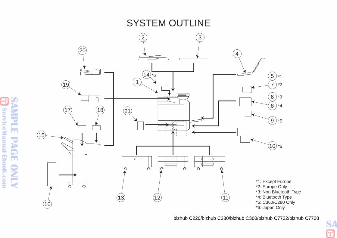
280/bizhub C360/bizhub C7722/bizhub C7728
*1
*2
*5
*4
*3
*5
*1: Except Europe*2: Europe Only*3: Non Bluetooth Type*4: Bluetooth Type*5: C360/C280 Only*6: Japan Only
75
8
9
10
4
11
6
bizhub C220/bizhub C
SYSTEM OUTLINE
*6
2 3
20
19
17 18 21
141
13 1216
15
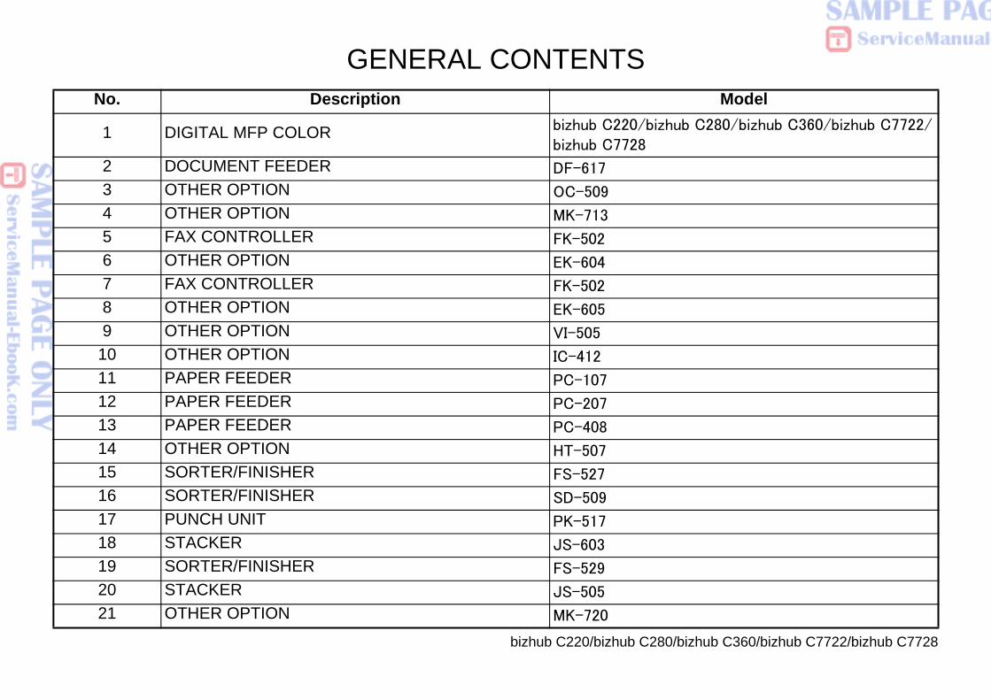
280/bizhub C360/bizhub C7722/bizhub C7728
Modelbizhub C280/bizhub C360/bizhub C7722/
bizhub C220/bizhub C
GENERAL CONTENTSNo. Description
1 DIGITAL MFP COLOR bizhub C220/bizhub C7728
2 DOCUMENT FEEDER DF-617
3 OTHER OPTION OC-509
4 OTHER OPTION MK-713
5 FAX CONTROLLER FK-502
6 OTHER OPTION EK-604
7 FAX CONTROLLER FK-502
8 OTHER OPTION EK-605
9 OTHER OPTION VI-505
10 OTHER OPTION IC-412
11 PAPER FEEDER PC-107
12 PAPER FEEDER PC-207
13 PAPER FEEDER PC-408
14 OTHER OPTION HT-507
15 SORTER/FINISHER FS-527
16 SORTER/FINISHER SD-509
17 PUNCH UNIT PK-517
18 STACKER JS-603
19 SORTER/FINISHER FS-529
20 STACKER JS-505
21 OTHER OPTION MK-720
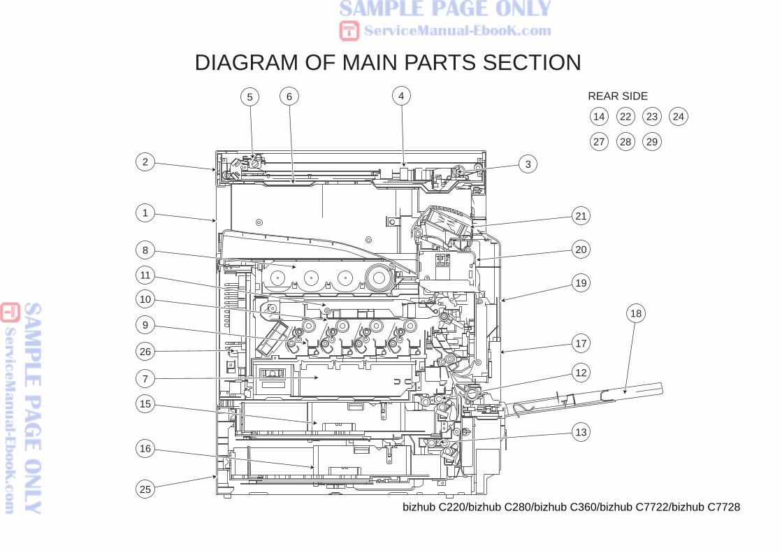
280/bizhub C360/bizhub C7722/bizhub C7728
CTIONREAR SIDE
3
13
12
17
18
19
20
21
14 22 23 24
27 28 29
bizhub C220/bizhub C
DIAGRAM OF MAIN PARTS SE45 6
2
1
25
8
9
10
11
7
26
15
16
KonicaMinolta Bizhub C220 C280 C360 service manual
KonicaMinolta Bizhub C220 C280 C360 service manual
KonicaMinolta Bizhub C220 C280 C360 service manual
KonicaMinolta Bizhub C220 C280 C360 service manual
KonicaMinolta Bizhub C220 C280 C360 service manual
KonicaMinolta Bizhub C220 C280 C360 service manual
KonicaMinolta Bizhub C220 C280 C360 service manual
KonicaMinolta Bizhub C220 C280 C360 service manual
KonicaMinolta Bizhub C220 C280 C360 service manual